#archived-shaders
1 messages · Page 224 of 1
Yeah, you could. That's what I meant by you pass some data into it defining the AO value of each pixel
Is there a built in fog shader?
I think you can just simply enable fog from window/rendering menu
so I can access the normals of a mesh using this node

and I want to fade out (or really just do operations) on a texture based on values from this node
I cant seem to just multiply it though
what needs to be done?
Can I do that for specific areas?
the built in fog is distance fog, which increase it's thickness the farther from the camera.
if you want fog which only affect specific area, you;ll most likely need volumetric fog
im trying to get terrain holes working on a custom HDRP Terrain Shader Graph, i'm using the correct reference as when i hook it into base color I can see the painted holes.
However if I split the Alpha channel and route it into the Alpha of the master node it doesnt work...anyone know why?


splitting Alpha into alpha master:

You're not feeding anything into the alpha though
You're feeding the color to base color that ignores the alpha channel.
Does someone mind giving me the Tl;dr on what "Depth Write" does and the implications of changing it's values for Transparent shaders?

I understand that there is a depth buffer and it's used to order meshes when rendering to the camera.
But the exact implications of messing with this... I'm not sure.
uh. does this server prevent long messages from going through or something? i just typed up a message and it ate it 🤔
If it included code or repeating sequences/strings/characters, the bot might've interpret it as spam. If you want to share code, check #854851968446365696
well thats a bit tedious lol. let me try to reformat
ive written a shader which manually implements shadowing from point lights, but have a couple very strange issues with it.
my main pass (done with lightmode tag set to forwardadd), requires the use of one of a few of the vanilla multi compiles. i can't fathom why.
i tried to narrow things down by cutting out keywords. the minimum spec one is
#pragma multi_compile_shadowcaster
otherwise, shadows do not work.
i have no idea why this should even interact with my shader. im not even using UnityCG.cginc in this pass.
meanwhile, on the shadowcaster pass, i can comment out its multi compile shadowcaster line and everything still works. that seems... odd?
my point light shadowmap is being copied into a new texture via commandbuffer. that and all other values relevant to the light are being passed thru script via globals
so tldr: one random pragma is preventing a shader with 0 relation to any builtin unity functions from working, yet strangely isnt even required in the shadow caster pass.
How would you go about dynamically changing the frequency of a sin wave in the graph editor?
Frequency is the rate at which the function parameter changes. So Just multiply whatever you feed into sin by some value(can be a parameter exposed to editing outside the shader).
the screenshot shows me checking the map works by feeding it into the base color yes, but when i change that and feed it into the alpha i get the bottom screenshot
Okay. Can you show the shader in the second case?
Also what graph settings do you have?


Ah, it's HDRP...🤔
i was assuming that the black areas of the splatmap are considered transparent, but that may not be the case, it could just be black / red, in which case how would i count the black areas as transparent?
Just use the red channel in the Alpha port?
ill give it a try


doesnt seem to work, i even tried to One Minus it so the black areas turn white then feeding it into Alpha, no change
AHA! I may have it
@kind juniper @regal stag Note to self:
Telling your Shader Graph to use Alpha Clipping doesnt make a blind bit of difference. Must always activate it in the materials inspector settings.
Because telling the shader to do it is far too logical.


Ah yeah, I forget HDRP has settings on the material for those too
XD
Do you know how to access the last 4 layers on the terrain BTW? i've got the entire thing set up, I saw a _Control1 declaration in the Standard Terrain Lit shader so am using that to access the second set of layers, also have a keyword bool with _TERRAIN_8_LAYERS as the reference but i still cant see the 5th layer
The first 4 work fine with _Control0

Yeah, does _Control1 show anything if you output it & draw with the 5th layer?
ill set it up and double check
Not sure if i've set this up correctly but:
_Splat4 texture is lerping over _Control1 then fed into the 8 Layers keyword bool:

results in:

keyword reference:

the T of the lerp is the R channel of _Control1

Hello everyone, I have a transparency problem ^^
I just want to clip stuff (The only possibility in shader is still alpha clip right?).
But even using 0.999 alpha I'm still seeing through the sides of the mesh. Any tips?
Thanks

It's the other way around.
I meant more like outputting the _Control1 texture directly to Base Color to see if it's even set to anything. Can also output _Splat4 and see if it looks like the layer texture. The setup should be similar to how the _Control0 is handled, but I'm not sure if the shader needs anything special to actually access the extra textures properly.
ahh ok ill give it a shot
You plug the alpha from the texture into the the alpha of the fragment shader. And alpha clip threshold controls what alpha value the pixel needs to have to discard it.
ok feeding either directly into Base Color doesnt show anything, so im guessing theres some sort of silly requirement to access those extra textures
Damn.. Thanks it make more sense (I had to reverse the color of my texture, it was weird) !
if this is true then WTF....why would they not just use a second control texture?

very detailed there Unity, nice one.

it clearly says HDRP can render 8 layers in a single pass though...

or should I try just using _Control0 and Splat4, 5, 6, 7?
_Control0 would correspond with the first 4 layers, it wouldn't really make sense to use it for the others. That answer is intended more for the built-in RP which uses 4 layers per pass, while it looks like HDRP is 4 or 8 layers and single-pass only.
@grand jolt The HDRP/TerrainLit.shader does seem to have a tag in it's SubShader, "SplatCount" = "8" which might be required?
But it says in a comment those tags are for supporting "shader replacement features" so not sure
It looks like _TERRAIN_8_LAYERS is a keyword from the terrain system so just enabling it on the material might not work. It might be a setting in HDRP somewhere? Or on the Terrain component? Or maybe it just sets it automatically based on the number of layers :\
I went into debug mode and theres nothing relating to 8 layers on the component itself, I added a keyword:

Curiously the terrain 8 layers keyword doesnt appear in the keywords?

ignore that, didnt have it turned on
it does now lol
Hello, I have a question. Here I have a transparent Shader Material, the thing is that I want to make it so you can see it from inside and outside of the material itself, how can it be done?

Here the inside, as you can see, it's invisible from the inside

did you use shader graph or code
Which version
Actually I'm working in 2019.4.12f1
Go to graph settings and activate two sided
its probably something like 3 dots on the main graph and might be called double sided in that version
Inside the PBR editor?
on the pbr graph
probably in the upper right corner
Ok I'll take a look in a bit. Thank you for the answer Max!
@dusk cobalt here's the graph. I don't have time to explain everything now, but it should be clear from the names of the properties. Velocity takes a normalized direction Stretch takes the velocity magnitude and stretch offset( -1 to 1) defines the point in the mesh that the stretching starts.

Is there anything like the scene color shader graph node for shaderlab?
Thx, i didnt know what to search but this is what i meant
That was my original attempt, but i dont know how to do it in a pixel shader, my original idea was to blur, normalize, smoothstep. But then i cant control the size of the individual dots, so i didnt know how to do it in a pixel shader.
? I thought all drawing apps basically draw a bunch of circles along the path of the stroke ?
Im gonna visualize what i mean, i think im explaining it badly 🥲
@torpid lichen I think they stamp alpha textures with a certain spacing.
If you want matrix printer dots, that's a different easier task.
Cause then you can just tile a pattern in screenspace.
ok but it comes out the same as drawing dots right ?
You're not going for pixelart, right?
wait im gonna send screenshot


Im not saying drawing the lines will fix the problems, i just want a kind of framwork i can use later to draw lines on top of frames according to a texture that tells the positions of the lines
I wanna do it this way so i can later manipulate that texture to smooth lines, introduce noise etc.
So as of 2021.2 - https://portal.productboard.com/8ufdwj59ehtmsvxenjumxo82/c/49-custom-struct-types?utm_medium=social&utm_source=portal_share is still not ready so I'm trying instead to encode some position/rotation/scale data from a compute shader for use in a ShaderGraph shader.
Is there a good way to do this? Actually I think I just need position/rotation, not scale
I guess I can use RBG of one pixel as the position and RGB of the next pixel as euler rotation angles, or the whole RGBA of the next pixel as a Quaternion for rotation.
Any water shader tutorial that talks about how to make it so refraction effects don't cause objects in front of the water to get refracted on their edges?
Check out ben golus' article on very wide outlines - that's probably the best starting point for what you are looking to do. I think the reason people keep asking if you are doing pixelart is because you keep saying pixel shader - usually you'd call it a fragment shader
Is there anything like the scene color shader graph node for Surface and unlit Shaders?
Yeah, multi-pass stuff and grab-pass. Try googling "unity grabpass".
In fact, here:
https://docs.unity3d.com/Manual/SL-GrabPass.html

How to make sword trace in hdrp? Because motion blur built in hdrp is kinda bad
Anyone know how to get a float4 quaternion representing the rotation from a float4x4 matrix in HLSL?
You could try this (I haven't tried it):
https://answers.unity.com/questions/750259/how-to-get-the-quaternion-rotation-from-a-matrix4x.html
Unity is the ultimate game development platform. Use Unity to build high-quality 3D and 2D games, deploy them across mobile, desktop, VR/AR, consoles or the Web, and connect with loyal and enthusiastic players and customers.
thanks I'll try it out
Thanks
A trail renderer maybe? I don't think motion blur was ever meant to be used for a sword trail or anything of that kind.
Is it possible to get the width and height of a Texture2D in shadergraph?
texel node
doesn't that get the size of a specific texel?
It gives the width and height of a texture
I don't think so...
Well I was also confused about the naming but it is indeed like that, feel free to try it
Ok i'll try it
Apparently in a normal shader it's a float4 with: 1/width, 1/height, width, height
but it's only width/height in shadergraph
weird

Making a URP shader graph. Trying to use a calculated position for the vertex positon. Why won't it let me connect this node here?

It's like my Vector3 node is somehow stuck in the fragment shader instead of the vertex shader. (It connects to the fragment inputs just fine)
How can I fix that?
Hmm it seems as though it's because I have a Sample Texture2D node in the graph. Is it not possible to sample a Texture2D in the vertex shader section of a shader graph?
Figured it out - have to use Sample Texture 2D LOD
I was about to link you my site 😛
Sorry for the monologue 😄
I'm not sure but my problem is still not fixed - it seems like there's some other node I'm using somewhere that may also not be available in the vertex shader stage
The behavior is documented in the docs though: https://docs.unity3d.com/Packages/com.unity.shadergraph@11.0/manual/Sample-Texture-2D-LOD-Node.html
https://help.vertx.xyz/?page=graphics/shader-graph/vert-frag is my docs for it. I don't really explain why though
I'm looking through every node right now to see what else in my graph is not vertex stage compatible 🤔
They seem to all be ok though as far as I can tell...
Vector3
Vector2
Multiply
Split
Object (position)
Matrix Construction
Sample Texture LOD
Divide
Modulo
Add
Texel Size
Instance ID```reconstruct it backwards from the vertex position and see what fails
hmmm
it seems to be... the Texel Size node?
Doesn't say anything in the docs about that being restricted though 🤔
strange but... maybe ok as I could work around this by passing in the texture resolution as a separate property if I need to.
a vertex shader output with SV_POSITION should be bounded to -1 -> 1 right?
            CGPROGRAM
            #pragma vertex vert_img
            #pragma fragment frag

            #include "UnityCG.cginc"

            uniform sampler2D _MainTex;
            uniform float groundHeight;

            fixed4 frag (v2f_img o) : SV_Target
            {
                if (o.pos.y > groundHeight) {
                    return fixed4(0,0,0,1);
                } else {
                    return fixed4(0,0,0,0);
                }

}```my thought was that this would cover a portion of the sprite its attached to (0 < y < groundHeight) and that i'd specify groundHeight as being between ``(-1, 1)`
wait i've done something wrong
Ghostrunner uses this
The vertex stage doesn't "know" about the screen pixel resolution (yet) nor the placement of the "depth", since that's output in clip-space. That's kind of a function of the rasterization stage that happens AFTER the vertex stage.
Therefore, it doesn't know how to select the right mip level (which is what LOD is doing) until the fragment stage hits.
Soooo.....when in a vert stage, you have to manually specific the LOD level you want in order to use a texture sampler. Thus you're required to use the sample-LOD call, since there is no default established for the lod level yet for the "normal" call.
Could this be the reason why my shader doesnt work in LoD? But the weird thing is that's the problem only happens on mobile device
#archived-shaders message
Thanks very Mutch
Hi, I have a question and require some help. I have about 100 objects that are all fractured to create a "chunk" which I then use to put all the chunks together to create land that I can destroy satisfyingly for the game im working on. I have about 9 chunks all loaded at once and so that creates 900 batches which just creates insane amounts of lag. I do however use the same material for each and every object. I am wondering if I can somehow use GPU Instancing or maybe something different in order to reduce these batches as I am creating for Mobile Devices.
The only thought I have is to duplicate my material 100 times for each different fractured object piece to enable GPU Instancing and to reduce batching because it only works when it is the same material + same mesh. Here is a preview of the mesh I am working with whilst using a Triplanar shader to draw the material:

Any help and advice is much appreciated!
what the?..

Switch it to sprite. Unlit shaders don’t work with UI elements.
where?

You seem to be using HDRP…. Try everything. I only know URP.
De nada.
I have a problem with my shader graph. I'm getting this error "DX11: Texture index out of range". Shader uses many textures (less than 128) but all texture samplers are connected to sampler state nodes. There are less than 16 sampler state nodes.
This graph uses StackLit mode. The thing is that it works fine and without errors when it's set to the 'Lit' material mode. Same inputs are connected to the master node so both modes use the same samplers when I test them.
does anybody happen to know how to do fake specular highlights in shader graph in URP? I want specular highlights on my water shader but if I just add a normal map, and set high metallic/smoothness it screws with how the shader looks a lot
Can i add second Material and Shader to Mesh?
Sorry to pull from something days ago but this doesn't work. All I get is "There's no upgrader to convert shader to selected pipeline"
not every material can be upgraded automatically
figured it out, I didn't have URP set up, but it can't upgrade most of the materials in my project (including the default ones) so I'll be going in a different direction unless there's a way to fix them
You can always upgrade materials. You simply need to switch them to use URP compatible shaders
Unfortunately the project is too far in development to have our artists re-do their textures for URP (unless there's a way I can convert the textures to work with URP?)
you don't have to redo any textures
you just have to change the shaders on the materials. (or switch to a new material with a different shader)
and reassign the textures to the right place in the new shader
ok, thank you!
You could try using DrawMeshInstanced and use multiple submeshes instead of objects. Not sure what are the submesh limits or how big of a performance impact it will be but I don't have any other ideas.
Hiya! Thanks for the response. I had ran a bunch of profiler and frame debugging tests and eventually just went with a mobile friendlier shader for most of my objects and turned dynamic batching on. Thank you for your response however
Thx a lot, yeah I see how I confused them, I thought the two were synonimous
Another kind of related question I had was is it possible to render the output of shader graph to a texture ?
Like a node that takes color just like the master but then writes it to a texture instead of the screen
I'm making a RenderTexture for use as an output texture for a compute shader.
The actual data I'm putting in the texture has nothing to do with graphics though. I want the data to just sit in the texture exactly as the compute shader wrote it (basically treating it as a big array of float4). What are the correct settings I should be using for creating this RenderTexture? For example I have no idea what to set for the format or for the color space conversion, or the depth buffer.


is there a way to create a tiling noise map within the shadergraph
Greetings gentlemen, what side-effect might appear if 2 different shaders have Vector1 with the same reference?
I'm planning to change materials using these shaders via one script, I can manually enter the new references into the script, but is there a reason NOT to just set the same references to Vector1/floats I need?
I'm confused by your question, the vector1 (a float value, basically) is going to be passed to the shader via the material properties by value on each shader that you set it on.
Yeah, I'm trying to ask about reference of a property. If n different materials/shaders would happen to have inside of them properties with the same rereference values, would that do any harm?

Thing is, I want to access the same property of copy-pasted materials with the same code.
Oh, the reference field in Shader Graph?
That's "just" the internal name within that shader. Since you have two separate shaders, they are independent references really. The word "reference" isn't really what you're thinking as it isn't the pointer type in C# that you might have in your mind. In fact, it is common to change the name (in this example) to "_OpacityStrength" (note the leading underscore) and that would be the property name in the shader.
And in c# you'd use something like
myMaterial.SetFloat("_OpacityStrength", myFloatValue);
Of course, it is always better to use a propertyID that you've stashed away, rather than making it do a string-name lookup every frame.
Yeah, thanks, it makes sense. I even used the same principle with texture2Ds, but for some reason missed that it's more general practice and can be applied to other variables :D
Dark side of blindly following tutorials, thanks!
i don't know much about shaders. is there a way to get sprite masks to render normal maps? the sprite mask only reveals the main texture.
Say I have two float3 representing euler angle rotations.
What would be the correct way to slerp between these two rotations in HLSL (compute shader)?
Simply doing lerp(a, b, t) between them seems like it wouldn't be correct, as you could have let's say 350 degrees and 10 degrees, with the proper interpolated angle being 0 or 360, not 175. Am I thinking about this wrong?
I guess represent them as quaternions and do a quaternion lerp between the?
I don't know if this is "correct" but finding the minimum angular distance between your current and target and lerping based on that seems reasonable. You should never be lerping more than 180 degrees along a given degree of freedom, so just checking if your distance is greater than 180 and flipping some signs/taking (360 - distance) if it is should work.
Will this float turn into (0.1, 0.1, 0.1, 0.1) or just (0.1, 0, 0, 0) when it converts to a float4?

I think the first case.
Has anyone used the new Instance ID node in ShaderGraph yet?
https://docs.unity.cn/Packages/com.unity.shadergraph@12.0/manual/Instance-ID-Node.html
It seems to always be giving me 0 as far as I can tell. however my material has GPU Instancing enabled, and I'm drawing it with Graphics.DrawMeshInstancedIndirect(itemType.Mesh, 0, itemType.Material, bounds, drawArgsBuffer);
So I can't imagine it's not being instanced. Also in the frame debugger as far as I can tell it's being drawn in one batch.
So is there some magic sauce I'm missing for the instance ID node?
I'm concluding that it's always giving zero because I did this and all the instances are still drawn directly on top of each other

I too ran into the same issue. All my instances are being drawn at 0,0,0
Im trying to get the positions from a args buffer that is being filled correctly no idea where and how im messing up
If it helps at all, this is what I had to do to get SG working with DrawMeshInstancedIndirect back in v10 : https://gist.github.com/Cyanilux/4046e7bf3725b8f64761bf6cf54a16eb
I think the Indirect version works differently from the regular DrawMeshInstanced. The new Instance ID node might only work with that one instead currently, but that's just a guess.
How many instances are you guys trying to draw?
If not in the many 1000's, you might be better off with regular Instanced calls anyway, unless you're procedurally generating the args buffer (and of course instanced data) on the GPU, say from a compute shader.
There's limitations to the # of instances in a call, but frankly, since there's probably no significant context switching going on, and the C# engine will do frustum culling for you, how bad are potentially a few more draw calls?
I'd time it each way if your use-case supports it.
Hi i've got some problems with making a pp shader only render if theres nothing in the depth texture that could "block" it
And it works great if you're directly next to it (the cube is rendered how it should be)

(the cube is rendered how it should be)


but if the distance gets a bit larger it just doesnt work
how can i fix it?
It is in the many thousands and the args come from a compute shader. I need instance id working 😅
I got a reply on the forum - seems promising https://forum.unity.com/threads/instance-id-node-always-giving-0.1193638/#post-7633861
Unity Forum
Software versions:
Unity 2021.2.0f1
Universal RP 12.1.0
Shader Graph 12.1.0
Has anyone tried the new Instance ID node yet? I'm trying it and it seems...
Right. Forgot about that. Im a bit sick right now and cant use my brain let me know if you make progress
I think for my case I might just go for dots since I dont need the objects to interact with anything at all
They just need to be there and play their vertex animations
I accedentally made a crappy edge detection xD

This doesn't sound right to me. The SRP Batcher won't override direct Graphics.DrawMeshInstancedIndirect calls. If it does, it definitely should be considered a bug, because there's no reason instanced draw calls shouldn't work alongside SRP batched draw calls.
I just tried it out. Disabling the SRP batcher doesn't fix it 😦
I was so ready to latch onto any bit of hope.
Have you checked the Frame Debugger to confirm it's actually instanced?
If it is, I'd like to see the generated shader code from the graph
I did check the frame debugger, but I'll do so again
Actually having a lot of trouble finding my DrawMeshInstancedIndirect call in the frame debugger
is there a good way to label it or something?
Is it even possible for DrawMeshInstancedIndirect to not be instanced?
yeah one sec
Pastebin
Pastebin.com is the number one paste tool since 2002. Pastebin is a website where you can store text online for a set period of time.
        void UnityGetInstanceID_float(out float Out)
        {
        #if UNITY_ANY_INSTANCING_ENABLED
            Out = unity_InstanceID;
        #else
            Out = 0;
        #endif
}```like based on that it seems like that #if is not being satisfied?
unity_InstanceID will also have to be set to SV_InstanceID somewhere, probably in one of the include files
would it be dumb to try manually editing this generated shader to do that?
in case that's somehow not happening
It looks like it's happening here
struct Attributes
{
     float3 positionOS : POSITION;
     float3 normalOS : NORMAL;
     float4 tangentOS : TANGENT;
     float4 uv1 : TEXCOORD1;
    #if UNITY_ANY_INSTANCING_ENABLED
     uint instanceID : INSTANCEID_SEMANTIC;
    #endif
};
INSTANCEID_SEMANTIC is defined per platform, like here:
https://github.com/Unity-Technologies/Graphics/blob/84384b4bb28d5bfcb8b19f2447dabd8fcd46e0c0/com.unity.render-pipelines.core/ShaderLibrary/API/D3D11.hlsl#L9
so that continues to beg the question why isn't it working T_T
I'm not ever seeing unity_instanceID assigned to the Attributes.instanceID or Varyings.instanceID
And it can't really be in an include file because a separate file wouldn't be able to reference that particular variable, except maybe through a #define
Supposedly it's assigned via the UNITY_SETUP_INSTANCE_ID macro
so many layers of abstraction
Which is never used in the generated shader
unless it's in some other include file
But yeah, I guess UNITY_ANY_INSTANCING_ENABLED might not be defined
#if defined(UNITY_INSTANCING_ENABLED) || defined(UNITY_PROCEDURAL_INSTANCING_ENABLED) || defined(UNITY_DOTS_INSTANCING_ENABLED) || defined(UNITY_STEREO_INSTANCING_ENABLED)
    #define UNITY_ANY_INSTANCING_ENABLED 1
#else
    #define UNITY_ANY_INSTANCING_ENABLED 0
#endif
Are these just preprocessor directives? Or are they based on some project or pipeline asset settings?
UNITY_INSTANCING_ENABLED should be defined for instanced draw calls, so UNITY_ANY_INSTANCING_ENABLED should be set
god I wish you could just attach a breakpoint to a shader
or print something
I feel like I'm trying to debug a magic spell
@shadow locust Do you see anything like this option on the Shader Graph? This will flatten out all the includes and defines you can actually read it.

This is a screenshot of the inspector with a regular shader selected
yeah these options are there hold on
Get ready for a huge file
One of my shaders is 125K lines, but that's handwritten so I expect a generated shader to be much longer than that.
Unity crashed trying to compile it lol
Did you select preprocess only? It shouldn't be compiling variants for that


This is from my phone because it's killing my PC lol
Seems to be stuck here >_>
But yeah just recreate my screenshot of the graph
I've basically reduced the graph to just that for now to try to debug
Why do I need to add the near plane to the depth?

Doesn't that break the depth being normalized.
(Orthographic camera case)
I copied this function from URP source code.
For SSAO I think.
_ProjectionParams.y is near, .z is far.
Oh wait...
Linear depth is not normalized, this is in world space.
I mean view space.
@shadow locust Did you ever try DrawMeshInstanced instead of Indirect?
Not workable for my use case
Yes I've done it in the past, but that was back when my project was using builtin RP
and I never had any trouble getting the instance ID when I was manually writing shaders
Holy crap, I'm actually finally getting somewhere with doing rain collision in VFX Graph.

Dang depth, why do they call it linear depth without specifying the unit.
Hey, back to a shader question… how do I remove the magenta from my textures?
I was using a custom code to read and remove the magenta by hand before assigning to the texture but now I have to use the resources folder
Remove it and replace it with what? Why's the magenta there in the first place?
Anything with 0 alpha... Magenta is there because it is how the original game client handles transparency
Anyway you could easily have a Shader look for that exact color in the texture and replace it
Or clip it
Thats what I came here to ask, if you'd allow me.. I'm not really experienced with shaders
Are you using built-in or one of the SRPs
Yes, the lightweight one I guess... this is the actual shader graph. I'm experimenting with the color replacement

This was the only way of getting somewhere close to what I want but the borders are not quite there.. What am I missing?


Does anyone know how to access _CameraOpaqueTexture from a shader?
You can!
You can inspect variables, and even hot-edit shader code.
BUT...you have to use graphics card vendor tools to do it.
So presumably Nvidia's tools, or AMD/ATI's tools.
If using SRP, try the SceneColor node. It has to be enabled in the settings (to capture the opaque pass to a texture). Sample it in a transparent material, since that's after the opaque pass, or any point (like post processing) that is after the opaque pass.
RenderDoc seems like a nightmare to use
Although... didn't realize Nsight existed 🤔
I've tried to like RD for years but I always go back to nsight
so... it's bit like blender, why fight the UX if it's clearly not designed for you 😅
DrawMeshInstanced works fine. I think I figured out the problem. I might be trying to do something that is simply not supported yet... https://portal.productboard.com/unity/1-unity-platform-rendering-visual-effects/c/61-support-for-drawindirect-drawprocedural?utm_medium=social&utm_source=portal_share
You would be able to modify the ShaderGraph's vertex shader to support custom vertex behavior for use with DrawIndirect or DrawProcedural.
I did some testing of my own, and yeah it worked with DrawMeshInstanced but didn't work with Indirect. It seems more like a bug to me though and maybe not something specific with Shader Graph. Have you written shaders that worked with DrawMeshInstancedIndirect on 2021.2?
I just upgraded to this version to try out this new feature (Instance ID node) so I haven't done much of anything on it
I can't really see how you can reasonably use DrawMeshInstancedIndirect without Instance ID at the very least so I'm really not sure how you're supposed to use it with shader graph at all if this doesn't work.
I'm already hackily using a texture as a data buffer shader graph doesn't support GraphicsBuffer/ComputeBuffer yet. This is so frustrating 😠
Time to write SRP shaders by hand....
I mean, you can only expect "easy tools" to do so much. IMO.
Perhaps it isn't supported for the vertex stage, but might work in the frag()? Anyone tried to see if it made it to the frag by remapping the instance ID to some colors?
Doesn't seem to work for either, but it's hard to tell because the only way I have to differentiate positions for draw indirect without instance id is to randomize them, unless I'm missing something.
You'd use the instance id node, and map it to different colors to see if it changes from 0 to anything else.
If you tried that, and it didn't work. It didn't work.
Right I tried that of course and it shows black but I can't tell if it's just the first instance drawing as black or all of them, as they all draw in the same position
Yes that's the plan
If so, you're getting all the same id...0...and they all end up in the same pos. But that's set in the vert?
Yep
I wouldn't mind if Unity had documentation and examples but they don't. Shader Graph is supposed to be the main way to make srp shaders
"Improved documentation" is on the planned list.
😂
🤣
anyway thanks for the help
Yeah. Wish I could have helped.
The thing is, without compute buffers, it's a PITA to mess with this anyway. Oy.
Does anybody know why terrain textures are power of 2 + 1?
I hack around weird stuff being on the edges of a terrain splatmap texture by clamping the uv with a 4 texel inset but I don't get why it's this way.
If I don't skip the 4 outermost texels I get color leaking from as much as 40 texels away onto the border.
Tried making a UI related shader graph

What am I missing here?
I even added it to my shader graph and I still get the error:

Ugh... so it needs to be exposed? I don't even use this feature...
So I'm new to Unity and I'm trying to use the shader graph to copy my Blender shaders, but I'm like 5 minutes in and I already encountered a peculiar error which I can't really explain
For some reason the scrolling intensity does not work in the actual viewport/game but it works as expected in the graph editor
Did you save it the shader? What does the graph look like?
Saved the shader before the depicted gif, yes. Gimme a sec, I figured I would update Unity to a newer version to see if that helped
I was using the 2020.3.22f1 LTS version
Will try with a newer one

Nothing complicated
@kind juniper Could you take a look and see if you see something glaringly obvious?
I'm not familiar with unitys shader graph
What's the value of Glow Intensity on your material?
And rune color?
HDR orange with 4 intensity
I should probably cut out glow intensity and just change intensity value of the HDR anyway
Afaik hdr intensity is not represented in the shader graph color node, I think there's another node that representes intensity.
Also, is the game paused by any chance? is timeScale set to 0?
Sure, but here I am multiplying with a value of between 0-1 from the gradient so it should lower the intensity
As the white will represent normal color while the darker areas of the voronoi should represent a darker blend
Just like the material preview
Works as expected in blender also
Not paused, no timescale to zero
Is it HDRP?
Yes
I think you need to pass in an Emission Node to the emission input.
https://docs.unity3d.com/Packages/com.unity.shadergraph@10.2/manual/Emission-Node.html
@kind juniper I'm apparently just too unfamiliar with unity -- it worked fine in the game view port, just not in the dev viewport
That's weird, but ok.🤷♂️
After checking through a ton of menus I think I found the problem
By default basically all render layers were unchecked
in the editor
The one that solved it was the "Always refresh" layer
@kind juniper thanks for your time anyways, I appreciate it
I'm not very familiar with hdrp, so no clue, but you're welcome.
@kind juniper One more question -- is the Normal from Height really so incredibly terrible?
pixellated mess

problem might be that there is some very sudden increases in value from your voronoi noise
so the normal changes very quickly and produces a pixeled reesult
idk though ive never succesfully used normal from height
The blender equivalent is just passing the texture into a bump conversion so I expected it to work the same in Unity
But it's literally ultra pixellated
All of it
Could be related to your texture resolution? I wonder where it goes from procedural data to the actual pixel texture.🤔

No way that is what is happening
Looks like this function is rendering it in chunks instead of pixels
Or something
Actually it doesn't seem to be completely pixelated. I think it might have to do with extreme values.🤔
Clamping does nothing
did you try it?
Yes
All the values are already between 0-1 as they just represent the amount of white so there should be no extreme values
clamping only changes the cutoff value where the normals arent being generated
So you are only "raising" or "lowering" the ceiling
Giving such a result:

Accidentally had the clamp into the strength there but same result without
I think this function is broken
Or it renders chunks instead of pixels
Doesnt appear to be in the same resolution as the source voronoi
But I see there is a different option to generate normals, Normal from Texture
But the texture input does not accept the output from the voronoi
yeah
For some reason
And there is no node to generate texture from voronoi either looks like
could you bake the voronoi texture
I could but that would completely defeat the purpose of the procedural aspect
btw thanks @woeful canyon @kind juniper for trying to help

This is the result I have from blender
The reason I want it procedural
Is because the actual UVs of my models are shrunk to a single pixel
Which I then move on a 8x8 color palette
To color it
So all the normals, smoothness, metallic, emissions etc have to be made procedurally
I think it might have to do with the uvs that you input into the voronoi node.
The UVs are generated so that doesn't make sense
All of these are made without using the models UV
I am 100% certain at this point that it's just a disfunctional node (Normal from Height)
have you tried testing it with a more basic case?
like just a procedural left to right gradient or something
Yes, it pixellates
yeah that sounds broken
It looks like it's rendering chunks of 2x2 by normalizing the 4 pixels
Meaning you only get 1/4th the resolution
classic unity
By using this function
I baked a texture and used the normal from texture and it worked normally despite equal values
So it appears to be just this function
yeah thats what people said
Which kinda breaks procedural UV mapping..
why do you even need it to be procedural?
Because then the size of the UVs of the object won't matter, the material will still appear the same
You just tweak the values to get different sorts of leather
Instead of having ugly ass tiling textures etc
You will have generated a never-repeating pattern
If you see the above screenshot of the sword handle -- the actual UV of the handle is the size of 1 pixel only
Yet it has details in a limitless resolution
how are you getting the voronoi to loop around the surface?
doesnt look like tri-planar mapping
is it 3D voronoi noise?
based on this, it uses ddx and ddy which cmiiw indeed sample pixels in 2x2
https://docs.unity3d.com/Packages/com.unity.shadergraph@12.0/manual/Normal-From-Height-Node.html
You wouldn't need to do triplanar mapping with a generated UV afaik
@tacit parcel Any feasible workaround?
I think you could do it by code instead of shader
make a custom node and write your own normal from height maybe
btw, I was expecting the node samples the neighboring pixels to generate the normal, yet unity decides to use ddx/y
how does it even calculate the derivative
on nvidia documentation:
"The specific way the partial derivative is computed is implementation-dependent. Typically fragments are rasterized in 2x2 arrangements of fragments (called quad-fragments) and the partial derivatives of a variable is computed by differencing with the adjacent horizontal fragment in the quad-fragment."
sounds like it is basically comparing neighbouring pixels
hm
"The partial derivative computation may incorrect when ddx is used in control flow paths where not all the fragments within a quad-fragment have branched the same way."
is there any branching logic in your shader graph?
from the manual above
float sgn = d < 0.0 ? (-1.f) : 1.f;
yep, seems there is
i mean like branching logic before normal from height gets called
because that apparently might mess up the derivatives and mess up the normal calculation
although when you tested it, it broke for just a simple gradient
so its probably broken even without logic maybe breaking it
It breaks no matter what looks like
Actually I'm wrong
Doesn't break if the gradient is onedirectional
Not that it helps me I guess
Just weird how unity lacks such a basic function
Blender has it
Btw, here's a good explanation from Ben Golus
https://forum.unity.com/threads/low-resolution-or-bad-anti-aliasing-on-normal-from-height.1051733/#post-6808757
The ddx and ddy functions work on a grid of 2x2 pixel groups (called pixel quads) across the screen, so if there's an edge that runs through the middle of a pixel quad it can calculate an approximate normal. If the edge is between two pixel quads then neither "see" it and you get no slope. Thus you get the above aliasing.
Unity Forum
I was playing around with blending two textures together to creating some tiles with "grout" or something between them. I figured I could make a tile...
Wow, beautiful
Pretty elaborate setup for what is just 1 node in blender but sure
If that's what it takes
i think you can export blender materials to unity though i dont know how successful that is
I doubt that tbh
Probably would register the simple properties just fine but I doubt it would transfer any functions
After taking a look at it I can't really replicate it for my shapes @tacit parcel
I wonder why the Normal from Texture requires a texture spesifically
The equivalent node in blender only requires rgb input
Well, you don't know how complicated the node that blender is using. It might be a performance nightmare in a real time render game engine. This kind of complaints don't really have any standing, unless you can provide actual arguments with data.
You are of course completely correct and I didn't consider that, my apologies.
I just want to recreate my blender creations in Unity and I'm just disappointed given that it doesnt really appear to be viable after all
It's not always possible and when it's possible it either requires specific proficiency with 3d graphics and shaders or hits the performance hard. Remember that Blender is made for realistic rendering and unity for real time rendering.
What's the name of the node in blender btw?
Bump
I don't think it should eat that much performance given it's 3 calculations per pixel that doesn't really need to change in real time after generation
Unreal appears to be capable of procedural normal map generation
But I despise c++ compared to C#
Fuck it I'll just bake I've wasted enough time as is
Nvm, that didn't work because my UV's are scaled to 1 pixel lol
That's when the triplanar projection comes to play.
In Shader Graph, is it possible to use a keyword to switch between opaque and transparent?
Right now I'm maintaining two basically identical shaders, with the only difference being one supports transparency and the other doesn't.
Having everything use the transparent shader isn't an option - that would mean I lose out on all the (very much used) benefits of a deferred renderer, and likely some other optimizations regarding shadow blending and such.
@grand jolt just write one transparent shader then change render queue at runtime
I guess that could work, but then I'm branching on the GPU as well as looping over every single material as they're created.
well, render queue is on the material so it isn't relevant to shader as long as the shader support transparent
i got a shader which uses vertex color to do some stuff. The colors are set in a particle system but it only works with the start color and not the color over lifetime
what am i doing wrong?
Guys its me again im sure youre so happy
So i need to sample the surface/vertex normal of an adjacent pixel in the fragment shader, is this possible in shader graph ?
i would have expected nor be able to input a position into the Normal Vector node but its not possible
Do i have to use code for this ?
Bglous does it again.
You can, as he implies, sample 3 points on your procedural height with tiny offsets between them, and calc your own surface normal that way, rather than using the derivatives. Pretty common way to do it, in fact, when you have height-mapped stuff. Google around for the formula. @mental snow
It's not that bad, it's "just" that it requires 3 sample operations (well two others and the current pixel). And voroni calcs can be expensive.
It's common to construct two vectors along the surface using the 3 points you know, and then do a cross product (see below) and watch out for handedness. (again google this stuff).
IDK but it might not be a shader question, it's a particle system question assuming your shader is picking up the vertex color properly. The particle system is on the C# side, unless you're in VFX-graph, then you need to use the VFX section.
How is your surface normal data stored? Is it a texture that you sample (normal map)?
If so you can sample the normal map to get nearby data.
If not, you calc it?
But otherwise the GPU only knows the ddx/ddy of the float3 normal value of the current pixel, that MAY be of use depending on what you're after.
From here: http://www.aclockworkberry.com/shader-derivative-functions/
Derivatives can be used to compute the current triangle’s face normal in a fragment shader. The horizontal and vertical derivatives of the current fragment’s world-position are two vectors laying in the triangle’s surface. Their cross product is a vector orthogonal to the surface and its norm is the triangle’s normal vector
But see the discussion above about some inherent "dangers" of DDX/DDY. In this case, though, since you're doing a derivative of the actual normal value being passed in per pixel, not deriving it, it should be OK.
I think. 😉
if the textures doesnt change at runtime (like, only generated once), I'd vote generating the voronoi heightmap and normal by code, less shader computation too
Agreed.
im calculating the angle between the view direction and the normal vector and display this value on the model
what i wanna do then is edge detect this, that why i wanna sample the normal left, right, up and down from the current pixel to compare them
i dont know if this is a stupid approach


Should i just bake the normals into a normal map and sample from there ?
baking them would make your life easier, IMO.
However, edge-detection (your real question) is an art in and of itself. There are many methods, and I'd start with researching them.
DDX/DDY is not uncommon though. But it tends to be one-sided as the GPU "sweeps" through things. So you'd "know" the change for left and the top, let's say, but not the right and the bottom pixel values.
Whereas if you can sample a map, you can get your !8! adjacent pixel values, if you want that many.
I don't know all methods, nor all code for them, off the top of my head, but it's a good research project. Some may require more passes than others.
Also research "outlining" and maybe "toon outline".
Unity has a tut on that too.
i intend to do simple 3x3 sobel edge detection, and then go from there in case it doesnt look good enough
Cool, sounds like you're "on the path".
yeah, i researched those, but they are not to my liking, backface culling leaves much to be desired and normal color edge detection too
Also unrelated but kinda related, is calculating ambient occlusion in shader graph realistic or should i get that out of my head ?
lol.
I'm not the one to ask, since I only EAT spaghetti, not draw shaders with it.
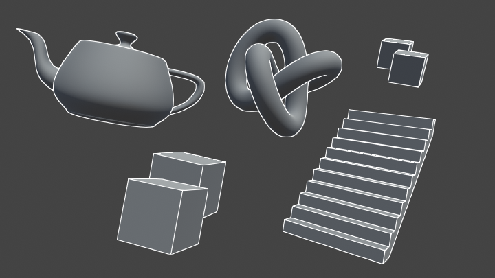
Hi all, are there any shader wizards that can give me a hand? I'm making a scene with a pre-rendered background in Unity, which combines the top-left image with a depth pass in the lower-left to give us a composite on the top-right.
I now want to be able to apply shadows to the scene, and I'm assuming we use a shadow pass, but I have no idea where to even start.

I'm confused, the top-right image already has shadows.
But maybe start with telling us what pipeline you're working in.
Shadows are "automagic" in unity when using lit shaders any any pipeline, for the objects themselves. BUT, if you're combining images in some sort of full-pass post-processing thing, you're probably looking to research "screen space shadows".
If you're adding shadows for the player character, I'd expect a lit shader to do that for you. But maybe I don't understand.
Greetings gentlemen, would anyone happen to know how to combine some effects of shader graph shader and just a shader?
I've got a cool glitch shader from asset store, but it doesn't work quite well with my sprites, since they are PNG files with transparent background. On the picture attached there's the Original Sprite, a weird way Shader Graph sees it, and a way to clean it with shader graph. But shader that applies desired effect is written in code, while my way of cleaning PNGs is done via shader graph. Is there a way to combine two shaders? Kinda give output of one to the input of the other? Or perhaps transform code into shader graph?

Yes, I should have been clearer. The top left image is a pre-rendered image from Blender, complete with shadows. My character in Unity can walk around the scene and go in front of and behind the pink objects by using a depth writing shader and the depth pass image in the bottom left. This all works fine, but now I want the character's shadow (which is non-existent at the moment) to be applied to the pre-rendered image in the background, as well as shadows from the scene to be applied to the character itself.
Here's a picture of the effect used in Resident Evil. The background is a still image but the character's shadows can still 'interact' with the environment, either by shader pass magic or by potentially using invisible geometry to catch the shadows.

I don't think that's still image

They are absolutely still images, the gamecube didnt have nearly enough power to do these realtime
Shadows on or from objects are CAST (and later received) by a shadow caster pass, in the lit shaders.
So if your character casts a shadow, using a lit shader, it should cast onto a <something>. The problem you'll have is that if they are images (I don't mean textures on 3D, I mean flat geometry) it's the shader for that/those objects that have to calculate shadows while drawing them or you distort the shadows into geometry shapes while casting them.
So somehow you'll have to either fake geometry data, and write your own custom shadowcaster pass to magically update the shadow map as if there was real geometry there, or the shadow receiving logic will have to account for that and distort the shadow map, similar to what you'd do with a decal.
I have no idea how to really pull it off, never having done it. But I'm dubious about doing any custom passes like that in SG, unless you do ALL custom lighting yourself using unlit shader and one hell of a set of sub-graphs to fake it all up.
And I still don't know what pipeline you're in.
You could try researching "screen space shadows" for some ideas. Maybe also related as I mentioned above....decals.
However mixing "canned" shadows and real time shadows is tricky...like I wouldn't. If I had to do screen-space shadows anyway, I'd probably do the whole damn scene and not have shadows out of blender.
Because you want scene shadows cast onto your player too, and you don't want double-shadows (hitting player and also not hitting player) if that's even possible. My head hurts now.
@tender orchid
This wiki indicates As a result, the graphical style of the remake features 3D models on top of pre-rendered backgrounds like early Resident Evil games.
https://en.wikipedia.org/wiki/Resident_Evil_(2002_video_game)#cite_note-NGC_Mag_preview-15
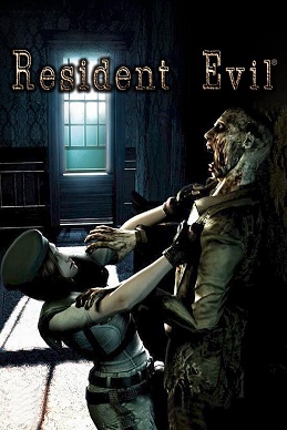
Resident Evil is a survival horror video game developed by Capcom Production Studio 4 and published by Capcom. Released for the GameCube video game console in 2002, it is a remake of the 1996 PlayStation game Resident Evil, the first installment in the Resident Evil video game series. The story takes place in 1998 near the fictional Midwestern t...
Verifying your original assertion.
At least we know it's possible!
I'm going to have another go at it tomorrow - I'm fine with having the original geometry in the scene to catch/cast shadows, just not have the objects themselves visible.
Adding the character's shadow to the pre rendered background is doable with the texture data you have currently, but if you want to the pre-rendered shadows to be on the character, you need a depth map from the light's perspective, not just the camera.
And those shadows will still be realtime shadowmap quality, not raytraced quality like in the render.
I'm fine with it being realtime quality, if it's good enough for Resi then it's good enough for me
Are you sure RE had environment shadows on the character? I'm not seeing that in the screenshot above
They pulled all that off in 2002 with a gamecube. They must have made compromises somewhere. It's just that many of the articles cited in the wiki that have discussions by the programmers are in Japanese...
Quick question, can you set the values of a gradient in a shader from a script and if so how?
Quick answer, gradients in SG (if you're in SRP) are calcs, so you could feed them in. See docs on the gradient node.
As for other methods, easiest IMO is to use a texture that you create in script. Like a 256 x 1 texture that you just sample from 0 to 1 in the x value.
ok thank you
You know what, I think you're right. The character models take light data from a point light to apply shadows to itself, but at no point do objects in the world apply shadows to the character!
The code for sampling the array is in the other node that samples the gradient. So the gradient is "just" an array.
Also see here:
https://docs.unity3d.com/Packages/com.unity.shadergraph@6.9/manual/Sample-Gradient-Node.html


window pane shadows....
I think some of the shadows are actually also from dynamic objects casting realtime shadows on other dynamic objects and the environment
I saw some examples of moving shadows, like from a fireplace
I think so too - zombies also cast shadows on him. I reckon that window pane is an object
@tender orchidAre you planning on running on low-end hardware?
If you're "OK" with having some geometry to receive shadows anyway, why not do a combination of real time and baked shadows and "just" have some normal-mapped low-res geometry?
That's what I've moved on to trying to do at this point
I've got it so objwcts have their mesh renderer set to Shadows Only, so they can cast onto the player at least
IDK why you even need to do that. I mean, texture mapped quads for walls and door parts, a few rough geometry for insets and stuff, windows panes....
These days, since you're not on a 2002 gamecube, you can pull it off with "real" geometry, if you get smart about keeping it low poly.
Just my 2 cents.
Then it all "just works". Why fight the engine? Do some tests on lowest hardware.
I could do it all realtime, but I want to stick to the late 90's pre-rendered vibe - the depthpassed BG images are an absolute must.
I can cast shadows onto fake geometry, I can receive shadows from said fake geometry, but the fake geometry is also casting a shadow onto the floor (along with its prerendered shadow). Should I try passing along the shadow map from Blender to do a shader that discards the shadow? Or can I tell the floor to ignore shadows from certain objects?
i remember that
pretty insane how they did it
it still holds up today, doesn't it?
ayy whaddup leon
meh looks really uncanny
like something's off
If I could cast shadows only from Player to Pink, and from only Pink to Player (no Pink to Pink), then I reckon that'd solve it.
Apologies for the large number of posts - just letting you all know that I figured it out. Correctly reading from a shadow pass texture did the trick.
Nice
Im trying to get an image with an alpha channel to work, but the standard shader has no options for this, Which one should i be using?
Hey! I'm trying to make an eye shader and one of the things I'm trying to do it put a top down gradient on it but I'm running into an issue.
Right now I'm using a position node to control the gradient. World works how I want it to work where I can rotate the eyes and the gradient doesn't rotate with it, but when I move the model up and down the gradient doesn't follow the model.
Object mode solves the moving problem but then the gradient rotates with the eye.
So is there a way get the best of both worlds? Gradient following but also not rotating with it?
World Position - Object Position should get you what you want. It'll be the world position relative to the world position of the eyeball.
@low lichen I just gave that a shot but its doing some funky stuff basically the causing the gradient to go up as the eye rotates up and down
I think I figured it out my eyes were being goofy
Hello guys, I want to make the typical hit animation that make the object go white and normal color fast. But I can't find any information about that. Also I need to make it with post processing effects so I need to use lit sprites. What can I do?
Trying to make an unlit shader graph in HDRP to use on the Image component... how do I make the vertex alpha function properly? This doesn't seem to work correctly unless the alpha is 0 (then it disappears)... any other value and it's 100% opaque.

Death's Door is just swapping between like 4 premade solid color materials on hit.
Super easy solution.
https://answers.unity.com/questions/845358/custom-shader-with-unity-46-ui-canvas-group-alpha.html
It seems that maybe I need to use the tag
Blend SrcAlpha OneMinusSrcAlpha
however, it's not clear how to do this in shader graph? Is there a custom function that could be deployed to route the alpha in correctly?
Unity is the ultimate game development platform. Use Unity to build high-quality 3D and 2D games, deploy them across mobile, desktop, VR/AR, consoles or the Web, and connect with loyal and enthusiastic players and customers.
Hey guys. I'm trying to generate an outline around a 2d character made up of multiple sprites (PSD importer, rigged). My shader creates outlines around each individual sprite within the character, but I'm trying to find a way to make it only go around the entire group of sprites. Is there any way to do this? I can't find anything on this topic anywhere.
Perhaps there is any way to input all of the textures from all of the sprites the material is applied to into the shader graph, so it gets processed as a whole?
@marsh gull you may need a postprocess shader to do the outline
Appreciate the response! Is there any tutorial or documentation for this process?
I'm also guessing it might be possible to separate the player into a separate camera, and then apply a shader to the camera somehow, but this is just speculation as there isn't much on this out there
Learn to write an outline edge detection shader for Unity engine, integrated with the post-processing stack. This effect is especially popular as a compliment to toon shading, or in CAD and architectural rendering.
normally it is for 3D but same tech
also there is another way, write a shader control all animations and write code to transfer animation to texture
then do the outline wthin the shader, but this is way complicated than post processing
however if you have 10000 characters ,this will save a lot cpu on play animation
That sounds like it would make me drop the idea entirely out of frustration, haha.
The post processing idea sounds like it has merit but I'm worried this approach would apply an outline to everything in the scene?
well that is the way everybody use,almost every outline asset sell on asset store use this way
Wouldn't really work in my case, I'm just trying to have outlines on specific sprites.
So far it has worked through a shadergraph + material for specific sprites that need outlines, but the issue I ran into is when I have a group of sprites that should share a single outline
no it won't draw outline on everything
ive disabled screenspace shadows and was under the impression they should fall back to light space shadowmaps, but instead my directional lights dont cast shadows at all
this happens in a blank project, any idea why?
im not using hdrp or anything
well for some reason, its suddenly working. just had to keep disabling things 🤷♀️
ok wait, ive got it and i think this is a bug
it only ever works if cascades are disabled. here's cascades enabled, obviously rendering the shadow maps correctly, yet not displaying on anything in the world

disabling cascades it suddenly works

using 2020.1.3f1
Apparently that's by design. Shadow cascades require screen space shadows to calculate the cascade areas/resolutions if I get it right.
https://forum.unity.com/threads/use-cascade-parameters-without-screen-space-shadows-enable.1012732/
Unity Forum
For some reason, I want to receive shadow per object instead of a full screen collecting.
It seems unity_WorldToShadow[0]~[3] won't update after...
At least in BIRP
thanks for the link!
that is very odd and definitely was not always the case.
I donno if it was different at some point - never tested it, but I don't think there were any changes to that area in the last few years. Might've been like that since unity 5 or even before.
that sounds about right 😛
<@&502884371011731486>
!ban @grand jolt Nitro Scam
 Faye#1806 was banned
I would like to have a shader graph that displays a texture on a procedural terrain. I was using the position node and all texture was stretched on some faces. The texture is mapped properly on view mode but I cant use that for obvious reasons. Any Ideas?\
What i want:

What i got:


so i have a texture, and i want to apply another texture over it with 50% alpha for example to simulate lighting
you can see in the left there are the two textures and right is 50% alpha black pasted over the grass texture
how could i approach this in a shader?
basically i want two uvs on two channel
first is texture
second is lighting texture and both are from the same material
and put lighting over the texture (not blend them)
You could project a texture from above by using the Position node -> Split and take the R and B axis into a Vector2 for the UVs. If the terrain has any vertical surfaces that'll still cause the texture to stretch though. If that's needed too, then you'd want to use something like triplanar mapping (a technique that samples the texture 3 times projected in each direction and blends based on normals). There's a Triplanar node to handle it for you.
Maybe just sample the same uv + offset(equal to the width of each square)
so I need some help here
my artist sent me a object, a shadergraph file and a mat file
however, the material is pink and for the shadergraph, i installed the shadergraph package and I don't know what to do
I set out the object in the scene, slotted it's material and tried changing its shader to the shadergraph that was given to me, but everything is still pink and stuff
it seems nothing was copied in relation to the shader graph

i have pasted the meta files aswell, does anyone know why this imported incorrectly?
It looks like the graph is intended for the Universal render pipeline. If you're in 2021.2 I think you can now add the Built-in RP as an active target in those graph settings instead, or you'll need to install the URP package (see https://docs.unity3d.com/Packages/com.unity.render-pipelines.universal@11.0/manual/InstallingAndConfiguringURP.html). Though it doesn't look like the graph is doing all that much, could probably just use the Standard shader (or an unlit one?) as a replacement.
You should probably also talk to your artist and make sure you both agree on which render pipeline you're using.
yea, it's definitely URP, I'm converting my project to URP right now (and fixing ProBuilder URP support as well)
the shadergraph supposedly should make the grass have a animation giving that wind feel to it
according to my artist
I need a little help
I wanna add a lightmap shader within the unity 3d standard shader
how can I do that
here is the lightmap shader
    {
        _Color ("Main Color", Color) = (1,1,1,1)
        _MainTex ("Base (RGB)", 2D) = "white" {}
        _LightMap ("Lightmap (RGB)", 2D) = "black" { LightmapMode }
    }

    SubShader
    {
        Pass
        {
            Name "BASE"
            Tags {"LightMode" = "Always"}

            BindChannels {
                Bind "Vertex", vertex
                Bind "texcoord1", texcoord0 // lightmap uses 2nd uv
                Bind "texcoord", texcoord1 // main uses 1st uv
            }
            SetTexture [_LightMap] {
                constantColor [_Color]
                combine texture * constant
            }
            SetTexture [_MainTex] {
                combine texture * previous
            }
        }
}```ah no, i need a second uv list applied in a different channel to it's pasted over the original texture, i already have to position of it in the code
but no default shader supports two uv channels
hello
So it seems that the shadergraph my artist gave me was not imported correctly
it's supposed to be a grass sway
is there supposed to be something more to import alongside the .shadergraph file?
If the graph doesn't have any other nodes I'd assume they gave you the wrong graph
hi! im making a mountain with the terrain tools, and i cant seem to figure out how to make the steeper parts of the mountain made out of rock, and the flatter parts of snow. i would like to do this with a shader. does anyone know how to do it?
your can get the vertex position, split it, and map the height coordinate to different colors
Guys i really dont wanna sound like a broken record, but just so im sure, does anyone know if it is possible to sample the normal vector of another pixel than the current one in either Shader Graph or HLSL ?
quick question: if I wanted to overlay this white dot on top of my texture how would I do that. most of the combining operators only seem to like black but I just want the white from this. (The dot needs to be white in the end)

Using Maximum or Blend with Lighten selected could work.
That worked!
Hi. Is it possible to have a disorting effect that disorts opaque and transparent objects behind it? I have found a grabpass filter https://gist.github.com/Refsa/54da34a9e2fc8e45472286572216ad17 which disorts transparent objects as well but disorts objects in front too which i dont want.

Gist
Unity URP custom grab pass. GitHub Gist: instantly share code, notes, and snippets.
you could just add it to the texture
Could but I want always want it facing towards the camera
is Shadergraph able to solve this overlapping problem?

Online I read about Stencil Buffers being used to achieve this but thusfar I havent been able to find a tutorial on how to achieve it
how do I add volumetric fog?
I just want things that are further away from the camera to become less visible and more blue (it's underwater) in specific areas
use regular fog (z-buffer or depth fog)

how can i make my texture trasparent in shader graph?
somebody suggested multiplying by the alpha channel but it just makes it black
it is transparent
just use the alpha channel
just because the nodes do not display it as transparency doesn't mean the data isn't there in the .a/.w coordinate
you're just discarding it right at the end
I forget what the nodes are, but it might be called Split?
you mean plug into the alhpa channel of the pbr master node?
If you want the output to have alpha, yes

umm it just makes it all transparent
edges are still messed up

ah no wait now i see
its out 4
do i just add a vector 4? 🤔
well, these operations don't make sense for a start

there's no reason to do this, so make sure you've removed it
yeah, that was just what someone on google suggested to fix this
how do i convert from a split back into a 1?
so rgb back into 1
also, what you did there didn't make sense either. That uses .r
you need to use .a from a split node.
Combine
just pass the out from the lerp into albedo, and the a from the split into alpha
worked 😄
ty for the help @vocal narwhal
now let's see if i can actually use the two uv channels lol
nope 😦
current shader

and my code
        mesh = GetComponent<MeshFilter> ().mesh;

        float x = transform.position.x;
        float y = transform.position.y;
        float z = transform.position.z;

        newVertices.Add( new Vector3 (x  , y  , z ));
        newVertices.Add( new Vector3 (x + 1 , y  , z ));
        newVertices.Add( new Vector3 (x + 1 , y-1 , z ));
        newVertices.Add( new Vector3 (x  , y-1 , z ));

        newTriangles.Add(0);
        newTriangles.Add(1);
        newTriangles.Add(3);
        newTriangles.Add(1);
        newTriangles.Add(2);
        newTriangles.Add(3);

        newUV.Add(new Vector2 (tUnit * tGrass.x, tUnit * tGrass.y + tUnit));
        newUV.Add(new Vector2 (tUnit * tGrass.x + tUnit, tUnit * tGrass.y + tUnit));
        newUV.Add(new Vector2 (tUnit * tGrass.x + tUnit, tUnit * tGrass.y));
        newUV.Add(new Vector2 (tUnit * tGrass.x, tUnit * tGrass.y));

        mesh.Clear ();
        mesh.vertices = newVertices.ToArray();
        mesh.triangles = newTriangles.ToArray();
    mesh.SetUVs(0, newUV.ToArray());
    mesh.RecalculateNormals ();

    newUV.Clear();

        newUV.Add(new Vector2 (tUnit * tOne.x, tUnit * tOne.y + tUnit));
        newUV.Add(new Vector2 (tUnit * tOne.x + tUnit, tUnit * tOne.y + tUnit));
        newUV.Add(new Vector2 (tUnit * tOne.x + tUnit, tUnit * tOne.y));
        newUV.Add(new Vector2 (tUnit * tOne.x, tUnit * tOne.y));


        mesh.SetUVs(1, newUV.ToArray());
        mesh.SetUVs(2, newUV.ToArray());
        mesh.SetUVs(3, newUV.ToArray());
        mesh.SetUVs(4, newUV.ToArray());
why is the second uv channel being ignored?
The blend factor is 0, the lerp factor is 0
okay blend set to 1, but i'm not sure what's the factor for lerp, the T?

i see here in the example they are using a split with in4 and out 1
how can you do that? 🤔
just link 1 to 4. You can create a float node and link it
or link whatever you need into it, idk what you're trying to do
lol, well i don't exactly understand what the T for lerp does, basically i want my UV2 to be overlayed over the UV0
T in lerp is the % to blend between A and B. If T is 0, use 100% A and 0% B. If T is 1, use 0% A and 100% B. If T is 0.5, use 50% of each
Try this? Note that blend is set to Overwrite. And if you need alpha to apply when blending uv2, send the uv2 alpha into the blend factor

hmm, overwrite literally replaces it, 🤔
here's an example of the final effect

so basically this will be the lighting for my textures
Yeah that's what overwrite does. I guess I don't understand what the goal is. You can change it back to overlay or whatever
i take one piece of the same texture
plop it over the other texture
and it simulates lighting
when it's fully black it just turns out black
so basically a copy paste of UV2 over UV0
The top left grey square has transparency right? Have you tried linking the alpha of UV2 into the blend factor?
the first block is just a black block with alpha set to 50%
Can also try this

ahh right multiply
lemme see

so it sorta worked
im displaying a pink number over the grass texture
but the rest of the grass dissapeared
lemme try with the 50% alpha block
If it's not shaded it should be multiplied by white

hmmm
well i'm thinking like this
i want that final color
but i don't want the alpha to apply
because the alpha will make the other block transparent as well
but how to multiply so it only adds the color of that semi transparent black over it
hmm, just add doesn't seem to do anything at all 🤔
You can just multiply the base texture by a value between 0 and 1 (white is 1, black is 0)


so i made separate textures to test
this is the result
and textures i used
if you multiply it's still too much black
You're multiplying by pure black so it's gonna output pure black. If you want a 50% shade multiply by grey

Oh and alpha should be 1 everywhere on the shadow texture

not sure this is the right way
if i multiply by pure black it's still visible
maybe i need to figure out the formula of what happens when a 50% black texture is pasted over the texture in the aseprite editor 🤔

applying 50% black to that red basically makes all rbg values in half 🤔
so i guess i take the alpha channel extrapolate it to a value between 0 and 1 and then multiply all rbg values by it 🤔
cause when it's by 0 it's gonna be 0 which is black
I have a big grid of sprites where each tile uses one of 15 textures. What would be the best way to render it avoiding a lot of draw calls?
I tried creating a texture array for the textures and setting a texture index per instance, but the instancing is not working (I believe it is related to this bug which will not be fixed it seems: https://forum.unity.com/threads/adding-an-instanced-property-breaks-instancing-when-used-with-sprite-renderer-properties.794325/)
hmm so it worked, i just linked the alpha channel directly into the multiply second value
but it's inverted
the more alpha the brigher it is
how can i invert it somehow?

invert colors doesn't work
cause i guess the alpha is ignored?
it worked with subtract 

it works!
thanks for the support @vocal narwhal and @plush fog !

here's the final shader
i'm back with another issue, i'm trying to make it so a different lighting hew is added to the lighting, yellow in this example

but when rbga is all 0 on the secondary lighting texture

it makes it look all weird
i don't understand why this is happening, if i'm adding just 0 to all rgb they should all be the same as before
this doesn't happen if i remove the addition
hmm even in the preview window it looks normal 🤔
Regular fog is in the entire scene tho?
It's all color math. And colors are "just" vector4 floats (float4's).
You can do it manually, as you're doing, or you can use some automatic blend modes.
But to see more about how to think about it....have you read this thoroughly? Including the alpha calcs?
https://docs.unity3d.com/Manual/SL-Blend.html
In particular:
finalValue = sourceFactor * sourceValue operation destinationFactor * destinationValue
there's tables for the different operations, and factors/values.
Like you mentioned something was inverted in alpha, which indicates to me that you should be using (1-alpha) somewhere.
And there's multiply, additive, etc. operations.
It's all just number crunching. There's really nothing special about it, other than maybe overriding alpha output in an opaque queue.
Grab a piece of paper and figure out what you want to happen with some sample values.
someone know where i can find some textures for a procedural Sand Dune Mesh Shader? Or a tutorial 🙂
So i figured out what was happening i think, for some reason when you leave a texture spot completely empty it fills those empty places with nearby rbg values(but not the alpha value) so when i added them they made weird shapes and blended awkwardly, so i put a condition that only in case of the alpha condition bring greater than 0 it should add, otherwise don't add anything
And it worked!
So I managed to get my artist's shader to work with a grass sway and everything. However, it seems that the shader doesn't compute shadows from meshes. Would anyone know how could I make it so the meshes actually project shadows into the ground/grass with the shader applied?

May I add, how can I make the shader accept Unity's lightning as well? It seems the directional lightning is not affecting the shader in any capacity
I have almost zero knowledge of shaders and this shadergraph seems complex enough and I don't even know where to begin
Can somebody help? How to remove OpenGL validation at runtime? Oculus does it inside their .so file - how can we do it in Unity?
Hi guys, i'm trying to make first steps with HLSL and right now trying to write custom function in shader graph. ShaderGraph gives me an error on my CustomFunction node,
Is this because ShaderGraph doesn't support some shader model? What i'm trying to do is to make an int from my float, so i want to use ceil or floor, but both produces and error. My code is simple as float intPresicion = ceil(Precision); or float intPresicion = floor(Precision);
As i can understand error says, that there is no such a function with 1 parameter, but msdn tell me that there is https://docs.microsoft.com/en-us/windows/win32/direct3dhlsl/dx-graphics-hlsl-floor
Returns the largest integer that is less than or equal to the specified value.
can you show the whole stuff like this?

anyways you probably need to define Output variable and do whatEverNamedOutputVariable = ceil(Precision);
I was thinking that there is some bult-in defenition for Precision value, so i have tried to replace it with Itereation name and error has gone, then i have wrote Precision name back and there is still no such error. But i have new, now "undeclared identifier ReplaceColor"
My hsls code:
void ReplaceColorCyclically_float(float3 In, float3 To, float Precision, out float Out)
{
    float intPresicion = floor (Precision);
    float3 colorStepHalf = (float3(1, 1, 1) / intPresicion) / 2;
    float colorReplaceRange = length(colorStepHalf);
    Out = In;

    for (int i = 0; i < intPresicion; i++)
    {
        float3 from = i * 2 * colorStepHalf;
        Out = ReplaceColor (Out, from, To, colorReplaceRange, 1);
    }
}
float3 ReplaceColor(float3 In, float3 From, float3 To, float Range, float Fuzziness)
{
    return lerp(To, In, saturate((distance(From, In) - Range) / max(Fuzziness, 1e-5f)));
}

oh, defining should go before call, lol
So how one would go to make a custom shadergraph receive shadow?
in a lit one, that is
That means parameter # 1. In your case "Precision".
How is Precision defined?
nm I see it above. Sorry.
@meager pelican all is ok for now, thanks. That was some mistake with variable data type
Hi guys 🙂
I'm seeking your council. I have some procedural terrain with a custom mesh. I'd like to have several textures (>5), therefore i would go with a splat map.
As far as I see and read, i would need non-shared vertices to get it to work. Actually, I already have a working splat map shader in shader graph.
However, I considered making use of the primitiveId and use per-triangle data, so i could use shared vertices and therefore massively reduce the number of vertices at the cost of additional lookups in a buffer. Unluckily, it seems that the shader graph doesn't support primitiveId yet, so I would have to write a new shader.
The map size is intended to be quite huge, so storage space and speed is definately important.
As I'm new to the topic, i would like to have a hint, which route I should follow: Use the shadergraph splat map with non-shared vertices or use a shader, utilizing primitiveId for per-triangle data. I attached a screenshot of my current status 🙂 Thanks in advance everyone!

how are shaders made?
i was searching for a good way to implement palette swapping shader, but i see now, there is no convenient way. I have found few
-
Hardcode color swapping, when you just define N color params and do replace color on each. So for different color number you need different shaders. Not the best variant
-
Main texture is a map itself to palette texture. Every pixel contains index to palette pixel. It can be done with writing to red channel or with grayscale.
The second one seems good for me. But i see problems: you'll have to generate mapped texture for every sprite you using with such shader.
Is there any tools to hook up import process and generate mapped sprite from given palette? Or maybe somewhere in the world exists generator for such images? Any suggestions? 🙂
Nice question.
I admit I'm guessing a bit here, but the additional overhead for accessing memory on your per polygon data buffer will probably cost as much or more performance than the shared verts, since you'd have to be reading from an additional buffer and that will impact memory coherence/cache. But I get your point about memory usage/size.
Any way you can code up a test case and benchmark? I'm curious as to the results.
Also, I'm sure you know that primativeid will lock you into DX 10 or later.
And be aware of this: https://github.com/Unity-Technologies/HLSLcc/issues/49
It occurs to me that there's probably several ways to "cheat" this process vs having one huge map. For example, break your terrain into manageable sized chunks, and take advantage of frustum culling. Then you'd not have to share verts AND you could somehow index into your own buffer if you still need to by calcing an index based on some data stuffed into the verts (I know that sounds wasteful too, but it'd be smaller anyway). And of course there's the whole procedural draw thing, were you don't even send full meshes, but IIRC you have to do your own frustum culling.

GitHub
When declaring an input such as // Input signature: // // Name Index Mask Register SysValue Format Used // -------------------- ----- ------ -------- -------- ------- ------ // SV_PrimitiveID 0 N/A...
You either write them manually, or use a tool like Shader Graph
But they are just code
I saw a brackeys tutorial with a shader graph. He made a cool effect can you make it just changing the properties or do u have to make it urself?
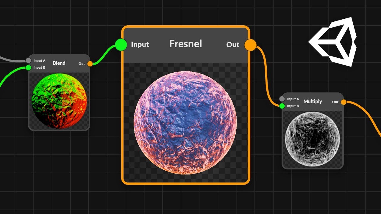
● Check out Bolt: http://ludiq.io/bolt/download
The time has come... Let's explore Unity's new Shader Graph!
♥ Support Brackeys on Patreon: http://patreon.com/brackeys/
····················································································
♥ Subscribe: http://bit.ly/1kMekJV
● Website: http://brackeys.com/
● Facebook: https://f...
you literally just linked a tutorial on how to do it. Try watching the tutorial and following along.
no its not that. like are you able to make that same effect but just with properties?
or do u have to use a shader graph for that
You have to make a custom shader to get a custom effect.
alr... tysm
Currently wrangling with Unity's support for GLSL shaders. Does anyone here know how to go about getting the tangent normals as a vec3/vec4? There is seemingly no simple answer online, as far as I can see.
Why not HLSL or CG?
Not really sure where this goes... but how would I go about having a texture that stretches across multiple meshes sort of?
Basically I'm thinking of like a 3d tilemap, so I'd have one big grass texture and that's supposed to stretch/repeat over the whole tilemap (but only for the grass tiles of course). Then a sand texture thats supposed to stretch/repeat over the sand tiles and so on.
I'm thinking either I have to somehow combine the grass tiles (even if disjoined from one another) into one big mesh. Or each grass tile would use texture UVs calculated as a modulo of its world X/Z position
Hello ! Do you know why it's showing me this error ?

what does that connection lead to?
It's connected to a lerp with a Vector 3 in A, and Vector 4 (automatically converted to Vector3 by the shader graph) in B

hmm is it supposed to be that error texture btw? :p
If not, wheres that left Add coming from on your first screenshot
It should be, but in game there's nothing strange x)
Ah

Isn't that the multiply?
But the place where the texture is first strange is here :

It's another thing that I add
The Negate of the MainLight direction seems to give the error
Is MainLight a custom node? Maybe that's the issue..?🤔
Although unlikely
What does the error on dot product say?
Yeah, I just realized that it was using a custom node, but still find it strange that it's working with these errors :s
'Invalid Conditional Expression' on every errors
It's not event conditional expression though...🤔
Maybe this is related?
https://forum.unity.com/threads/invalid-conditional-expression-in-custom-function.1043452/
You have to know how many meshes in the shader.
If you have 2x2 meshes, each set of UV's would be adjusted to 1/2 what they'd be for a "normal single mesh" with starting offsets. So lower left would start at (0,0) and go to (.5, .5), and upper left would start at (0, .5) and go to (0, 1), etc. You could set them in the modeling program individually, or you can procedurally calc them.
Also, as you implied, you can "just" calc them based on world space coordinates, and tile them like you said in your last line.
As for combining, it's commonly done with a splat-map, like the terrain system uses (google them). That lets you blend between grass and sand. But you could, if you choose, map each triangle even to one or another texture and not blend at all! All up to you.
Hmm I see. Will google splat map and try around with the other things, thanks~
Hi, i have a question. I want to create a shader that makes objects look like plastic, but i want the shader to use the objects material color
how can i fix that
Hey, i need help with my shader. i made a shader where the steep parts of the mountain is made of rock while the rest is made of snow. I did this in HDRP. Theres one problem though. The shader is pink, and i cant upgrade the materials because its a custom shader. Anyone know how to fix this? thanks
That means that the shader is broken or incompatible with the render pipeline. Is it shader graph or a regular shader?
its a regular shader
Do you have any errors when trying to compile it?
Share the shader code.
one sec
no errors, but heres my code:
Shader "Custom/Terrain" {
    Properties {
        _SnowColour ("Snow Colour", Color) = (0,1,0,1)
        _RockColour ("Rock Colour", Color) = (1,1,1,1)
        _SnowSlopeThreshold ("Snow Slope Threshold", Range(0,1)) = .5
        _SnowBlendAmount ("Snow Blend Amount", Range(0,1)) = .5
    }
    SubShader
    {
        Tags { "RenderType"="Opaque" }
        CGPROGRAM
        #pragma surface surf Standard fullforwardshadows
        #pragma target 3.0

        struct Input {
            float3 worldPos;
            float3 worldNormal;
        };

        half _MaxHeight;
        half _SnowSlopeThreshold;
        half _SnowBlendAmount;
        fixed4 _SnowColour;
        fixed4 _RockColour;

        void surf (Input IN, inout SurfaceOutputStandard o) {
            float slope = 1-IN.worldNormal.y; // slope = 0 when terrain is completely flat
            float snowBlendHeight = _SnowSlopeThreshold * (1-_SnowBlendAmount);
            float snowWeight = 1-saturate((slope-snowBlendHeight)/(_SnowSlopeThreshold-snowBlendHeight));
            o.Albedo = _SnowColour * snowWeight + _RockColour * (1-snowWeight);
        }
        ENDCG
    }
}
Start from changing CGPROGRAM and ENDCG to HLSLPROGRAM and ENDHLSL
Then you'll get some errors that you'll need to solve by changing CG stuff to it's counterpart in HLSL
It's more to do with that it's a surface shader, which isn't supported in URP and HDRP
Oh, guess that too.
I'd recommend using shader graph though, writing shaders by hand in HDRP is a nightmare from what I've heard
i have no clue on how to use the shader graph :/
then it's more likely you will have even harder time doing custom HDRP shaders
in short, Unity doesn't want you to do custom hdrp shaders
basically you could take stock HDRP lit and modify it if you really need to but would be just so much easier to use SG as it will not break on every second future HDRP release like your custom HDRP shader will
are there any other ways i can acheive a look like this?

that's typically done by precomputed mask texture
then just layered few materials with a shader
or use some kind of terrain shader if it supports that
Hi, got a quick question, I made an outline material shader with ShaderGraph, and I want it to apply to all objects when rendering on a secondary camera, how can I achieve that ? I tried searching online but no solution worked so far
Probably with this:
https://docs.unity3d.com/ScriptReference/Camera.SetReplacementShader.html
I tried using this, and either my shader doesn't work with this system, either I am not using it properly. Could it also need the meshes to already be present in the scene to make the shader replacement ? I am loading my other scenes (which contained the meshes) additively after my main scene start
I don't think so...🤔
What's the issue though? Does that camera not render them at all? Or renders with the wrong shader?
Which render pipeline are you using? Replacement shaders are only supported in built-in afaik. URP has an override material which is similiar, the RenderObjects feature on the Forward/Universal Renderer asset can do that.
it renders using the object's base shader
I am using the the URP, are there examples using RenderObjects or other functions to override on a camera ?
I saw it existed but didn't look into it much as it said it could be unoptimized to use
There's an example on how to use the feature here : https://docs.unity3d.com/Packages/com.unity.render-pipelines.universal@11.0/manual/renderer-features/how-to-custom-effect-render-objects.html (You'd just need the Material override, not the depth parts though)
You can create a second Forward/Universal Renderer asset somewhere in your project files and assign it to the list on the URP Asset. Then on the camera switch the Renderer, that way it doesn't affect your main one.
it's working ! only problem left is that my white outline became black for some reason but I am definitely much closer to the solution, thanks for the thread !
though now I need to figure out why it does this ^^
actually it's fine, I just used the wrong processing event, all is in order ^^
Quick snap at the first pass of my (mini)map feature it renders ^^

@meager pelican can I get a reminder when I am supposed to use .DrawFullscreenMesh() and when to use Blit() for fullscreen effects?
The ability to reproduce the same shader in Maya is one of the deliverable requirements, so GLSL was determined the way to go, since the changes required for porting are minimal.
https://youtu.be/vIh_6xtBwsI could somebody please explain to me why did the person split the Absolute World Position to obtain the X and Z value, and then have it plugged into a Vector2 node to obtain a texture that projects only at the top? starting from timestamp: 4:20

Tutorial on how to make a tileable material in unity shader graph.
Works in HDRP or URP
This works great for walls and floors or other objects that use a seamless tileable texture
i'm genuinely confused
The position is a Vector3 (xyz), but to sample a Texture2D it requires a Vector2, hence the need for the Split and Vector2 nodes. The X and Z is used since those are the axis involved with the top surface. The Y isn't used so the texture stretches on the side, but I'd assume later in the video they project textures from other sides too and blend based on normals. There's also a Triplanar node that does it for you.
Absolute world space is used so moving, rotating and scaling the mesh doesn't change the projection.
I'm trying to make a ray marcher in unity using hlsl
And instead of a sphere, it gives me this:

a powerful website for storing and sharing text and code snippets. completely free and open source.
Here's the code
I have a warning: implicit truncation of vector type
Uh, what the hell is .DrawFullscreenMesh() ? 😉
URP SSAO uses it instead of blitting.
It draws a quad scaled up to match the whole screen.
So instead of mixing stuff manually in the shader they draw the SSAO on a quad with alpha.
Well, the good news is do does blit (the fs quad). And blit let's you pass a material.
But I'm obviously not the one to ask, maybe someone else knows.
I'm curious now though, so may dig further.
No, with blit you feed the camera target and you have to make sure to output the old pixels where your special effect has 0 alpha.
With draw fullscreen mesh you can just dump a (0, 0, 0, 0) out and it won't give a shit and will blend on top of your screen target nicely.
At least that's how I think.
Oh, you're saying you can use alpha blending and just blend into the back buffer.
Sounds like you've answered your own question, beat. 😉
But when do I pick one over the other.
What are the perf implications.
I can't be writing "skills: shaders" in my resume if I don't know this 😄
I would think that the fsmesh call with blending would be faster, if you don't need to know what you're blending over (but I haven't dug in yet), so I'm grasping here. SSAO would have to have read that somewhere, and then "just" blending the result over top with that fsmesh call. Like as a final step after it had the shading info for AO.
SSAO isn't cheap.
Oh, I know how SSAO works.
I just don't know how to learn stuff like that.
The whys.
But but but....
You just learned it, explained it, and then educated me. 😉
It sounds like...that they're doing that final call just to blend the result in using alpha blending per your explanation.
Yeah, but why not blit.
It's not the only builtin render pass in URP I've seen that uses fullscreen mesh.
YOU answered that. Blit gives you the OLD target, and a new target, and you'd have to be:
- reading the source.
- writing to the destination
AND - adding in the AO result. So that's reading 2 things and writing 1 new one back out.
As compared to taking what you have (however long it too you to get it...and that's no slouch with AO) and "just" splating that on top of whatever you already have in the back buffer. Like shadows do. That's one read input, and a hardware blend output to the back buffer.
I think. That's what it sounds like.
So I'm GUESSING that's why they did it.
BUT...IDK how long it took to get the AO results to AO Map back on top of the screen.
But the GPU is going to be designed to "dump" stuff blended into the back buffer. Like fast.
Hmm, true.. AO pass needs the depth prepass target but not the camera color buffer so we save 1 texture tap since we are no longer blitting using the camera target as a source.
Yeah, since the depth is often/usually "free" with the back buffer.
Nah, URP uses depth prepass target rendered before everything, not the camera's depth target. We also got depth priming recently so maybe URP maybe also uses that same prepass to prevent overdraw even.
But pre-pass just means WHEN/HOW they get the depth buffer populated. Right?
So...they do a pre-pass. No pixel shader necessary. It basically "just" writes depth information to the back buffer, colormask 0 basically. Only depth info gets output, IIUC. At least that's the goal... have the vert() do its thing, position the triangle, and then rasterization just outputs the interpolated depth across the triangle for all frags and doesn't even call any pixel shader.
I think.
Pretty fast.
And then you have a depth buffer sitting around for all the good stuff in later passes.
I just mean it's a separate render texture, not the "live" camera target.
Oh, us programmers and semantics 🤣
So you need it for the pipeline anyway.
I just meant that it's "free" to the AO process later.
That gets complicated IIUC, and may be (is) implementation/hardware dependent. Sometimes Unity makes a separate one, sometimes it is a hardware one. I get confused as to when it does which, to be honest. And it's part of the RT setup.
Maybe it makes one if you have to read it, but otherwise if you're just doing hardware z-testing it "knows" it won't need it. Not sure.
Well, it comes from cmd.GetTemporaryRT() so I dare the GPU to remove it 😎
How can I make a gradient fog effect?
So in this video, in the area where the shader cuts off the mesh, a texture covers the cross section
https://www.youtube.com/watch?v=o8PdPdcbMzk&ab_channel=AbdullahAldandarawy
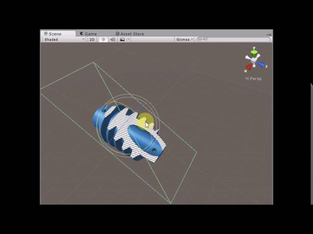
Unity3D Cross Section Shader
Live Demo : https://dandarawy.github.io/Unity3D-Cross-Section-Shader-Demo/
Download from asset store:
https://www.assetstore.unity3d.com/en/#!/content/66300
Github:
https://github.com/Dandarawy/Unity3DCrossSectionShader
How exactly do you get this effect?
(Specifically something like Shader Graph 😛)
Remy has an example of a textured cross section shadergraph here : https://github.com/Remy-Maetz/ShaderGraph_Doodles/tree/master/Assets/Shaders/CrossSection
Oh thanks. Exactly who is Remy?
Unity dev that sometimes talks here, they shared it a while back #archived-shaders message
Is there currently a plan to add a node similar to Blender's ColorRamp?
I think the Sample Gradient node is similar?
Kind of, but it's also kind of a pain
And the noise options are way more limited
Had to abandon a project because Unity has no wave texture node
Previous versions of Shader Graph contained PBR Graph which had AlphaClipThreshold parameter in its master
How can I set AlphaClipThreshold in newer versions?


How would i do something like this in 2d

without actually making it part of the texture
minecraft textures when


transparent material usually ignores zbuffer

Can you have multiple shaders apply to a single material at the same time? Like an outline shader on a mesh that has a pbr shader as well?
So, odd issue that maybe someone here can help with... I'm working on building an identical shader in Unity and Maya, and am getting different results in the two programs with what should be identical inputs.
Left is Unity, right is Maya. A simple swizzle of a vec3 fixes the mirroring issue, but for some reason the normal data in Unity displays as much smoother than Maya. Anyone know why this might be, or how to fix it?

Maybe the interpolated vectors in the vertex shader aren't normalized in Maya?
I'm not sure if that's the issue. Applying normalization during the Pixel Shader stage doesn't seemt o make any sort of difference to the output color.
At least if my understanding of your suggestion was correct.
can anyone help me with trying to get a boids project working in hdrp?
specifically https://github.com/Shinao/Unity-GPU-Boids
or at least point me in some direction on how i can try figure it out myself
i assume the compute shader works the same on all pipelines but normal shaders and specifically surface shaders dont with hdrp
i tried looking at shadergraph examples that have a structured buffer as i assume that's important for the optimization of this boids implementation but couldnt find much
any help would be really appreciated
I assume trying to get this (https://github.com/Shinao/Unity-GPU-Boids/blob/master/Assets/8-GPU_Boids_Final_Clean/Boids.shader)
to work in hdrp isn't a simple process at all but i've looked for resources for hours and thought maybe someone could help
can someone please help me. pbr graph is gone and idk how to make the shaders now
What render pipeline are you using?
universal
and it just shows lit shader graph
unity said they removed pbr
that's it
but how are we supposed to make the shaders now...
what's wrong with lit shader graph?
it has a vertex and fragment thing
and i follow brackeys tutorial
what's wrong with that
If it's pink then you're likely not using URP properly
wdym
If you create a material that uses a built-in URP material does it display properly?
or is it also pink
how do i do that...

let me try and make the shader again
how would i then apply the shader to the material
you don't need to do that
just use the default URP material, it should be preset if you create a new material if you are using URP
the mateiral is still pink
Then you are not actually using URP
i set the shader to URP/Lit
and then i made a new shader graph
lit shader graph
and made the shader
i installed URP @vocal narwhal
If the default lit URP material displays in pink, then your project is not configured for URP.
do i have to do more than just installing it in package manager
Yes.