#archived-shaders
1 messages · Page 223 of 1
There’s no way. You can use both sided shader but you cant cull front
You can implement the culling on your own using transparent cutout
Ah yeah we tried figuring this out in the #archived-urp channel to no avail as well. Such a bummer that it isn't possible out of the box
I think I saw a unity rep mention something about letting devs create their own master nodes (the final output nodes.., not sure if they're called this)
that could potentially solve it but it seems a bit overkill
You could use Is Front Face node to do that on your own but internal culling doesnt work
like.., to do frag discards with?
Yes
should be fine for prototyping I guess.., it just feels like it's going to be slower that way.. uugh
icky situation 😄
Yeah, it may be slower
almost tempted to tell the artists to create shell models for all assets, haha
When the shader is ready, you could generate the shader code and change the culling option but that may not be any less icky
yeaah that crossed my mind as well
On some areas, shader graph is just bad
amplify shader editor is looking very tempting. I've been dabbling around with shader graph (like really giving it a chance) but there's just some things here and there that is.., uuh.., not the best
I really wish it were better. the other thing i've noticed I don't like is that it totally breaks when I have custom nodes where I change the code and the output or input doesn't match and unity goes crazy on me
not the biggest issue but it goes into the icky jar, hehe
I think shadergraph alone would be able to do this.. what if.. and what if, set it to transparent then branch them out with IsFrontFace node to the alpha? this is just a guess
Wouldn't be the same as telling the graphics card to do an actual cull. But I see what you mean. Visually it could be identical (although I wouldn't do it set to transparent but rather using alpha clip or some discard function)
yes, you can switch to alpha clip if you want


ops sorry
any ideas how i could make it look goog?
add more samples?
sorry i posted the wrong screen shot
your screenshot is too blurry
wouldnt that like completely destroy my gpu
I wrote something in the search bar but somehow it ended up here in the chat
I'm on a phone so the node tree looks blurry to me


What's the underlying issue you're trying to solve? Like if you want a blurred rectangle I'd first check if you could use a texture directly instead?
I'm assuming there's something more to it though
yeah the falloff should be adjustable
You could probably do it with a custom node. How much experience do you have writing shader code? (and if you don't would you like to learn?)
not much
i made a raymarching shader once but thats it
(well atleast thats the only one that worked)
That's plenty advanced hehe :)
Would be doable with nodes as well (depending on the exact result you're after)
I tried like making like 10 different shaders and only that one worked ;-;
so whats your idea?
ew
i tried making a keyboard emoji and that came out
wtf was that
sorry just keep going
I'd suggest looking at the x and y channels of your uvs and try remapping them to something squarish
Hmm what exactly do you mean?
Yeah sorry that's a bit too broad. But that's what I'm thinking.. If I were at the computer I could probably whip something up for fun for you.
But in the meantime I'd subtract the uvs so they are centralised add an absolute node so it goes from 0 in the center to positive values in all directions
And then remap the gradient to be sharper (I think this is where you need to split it up in x and y or red and green)
And then add it back together and you should at this point have something square looking
Does this make any sense to you?
Hope it works out. Post the results later :)
I'd probably combine the resulting vertical and horizontal gradients with a multiply btw.
It is kinda square-ish

Yeah split it up! And add a remap node to each channel! :)

yeah you need to split it up first
i did
this was without
Oh. How did you get that then?

Yeah you'd preferably go for white center and black borders right?
Sorry to micromanage but I'm invested now 😋
I... think so?
so just 1 - ...?
I think there's a node called remap
Where you can set like a range before and after..
i used that one
Hmm the remap node is always confusing for me (I like to fiddle around until I get what I want) but I guess your in min max could be like 0.4, 0.5 and the out min max to 1, 0
So it goes full white at 0.4 and then black at 0.5
Unless I'm misremembering how it works
Increasing the distance between the in min max (or decreasing it) would be your adjustable falloff
it should be min 0 max 1
because uvs go from 0 - 1 right?
Well you'd want white in the center no? So that's why I flipped them
btw, u told be how to generate the brackeyes logo xD

Haha what? That's funny
oh i just 1 - it
Ah I see. Yeah whatever works :)
But it still looks lika a diamond shape. Did you really split the channels up into two parts?
yes
Care to show more of the node tree?
i added them together
ill show u
Ah yeah of course. Sorry if I'm jumping to conclusions :)

That looks great. I think it's possible to combine them with a divide (I'd prefer a multiply and flipping so the center is white at the remap stage)
But that's mostly because I think it would feel cleaner. I guess both methods are valid
You mean the diagonal lines in the resulting shape?
the currently vertical and horizontal lines
Well if you do use a divide or flip and use a multiply you wouldn't need to rotate it.
I'm not sure what you mean with less strong but preferably after your remap it would go from 0 (or 1) a bit outside the center and then full 1 (or 0) a bit before the edges
And if you have a white center you should use a multiply. And I believe if it's the opposite you should use a divide (instead of your add)
As long as the center part of the lines have a thickness (the part that should be completely 1 or 0) you should see less of a diamond shape
What should end up happening is a square shape with sharp diagonal corners. If you really want rounded corners we'd need to do it a bit differently I guess
(sharp in this case is 45degrees. They would still have a falloff like the rest)
Oh actually now that I think about it you could probably use a length node to do rounded corners. But I'll go on about it after you tried this out and if you really need it
Tried it as well at the computer.., Turns out I forgot the remap nodes doesn't add clamping so I added saturate nodes immediately after.., otherwise it's more or less the same as yours

higher rez pic

@slim steppe
Question:
Has anyone here used the Substance in Unity Package and managed to make a sbsar with emissive output get converted into a Material in Unity?
Hey is there anyone here with a bit of knowledge of shaders in Unity? I found this simple outline shaders, although there's a small change I want to make. Currently the shader is kind of transparent and hard to see from a distance, I was wondering if one of the variables could be changed to easily make the shader less transparent. https://hatebin.com/ytqntvskrp
I already checked if the colour I set in the inspector had a low alpha value, but it's already at max. Any help is appreciated 🙂
I guess you could try making it completely opaque and disregard all transparancy in the shader. But also.. The common trick is to push the vertices along the normals but here it just seems to be scaled. Looked a bit weird to me but I guess it can make sense depending on the circumstance but just as a fyi
How would I turn it opaque though?
I believe you just need to change queue transparent to Opaque
I did that, but it doesn't work, plus it gives an error.
What's the error?
How would you make variable transparency throughout a mesh?
like some parts if 25% transparent
others its 50%
The error: Shader Custom/chr_outline uses undefined Queue: 'Opaque'
Could be done through a texture, vertex colors or something else. Maybe explain your problem further?
Ah. It could be "Geometry"
Well lets say I want a gradient of transparency throughout a mesh, so it looks like the structure fades in.
No, that just messes up the view.
The best thing would be to map some values on a texture to alpha values at that point
that would be optimal
ohhh
I found it
There were a few options to choose from, but apparantly I could make the value even higher, which makes it less transparent
Thanks for your help 🙂
Thank you so much!
Ah, fades in like in it animates? Or do you mean fade as in blending with another object?
Animating transparancy based on texture values sounds very reasonable
Kinda makes me wish I could watch what happens in the frame debugger cuz it sounds a bit weird :D
But glad it worked out!
ya so basically I have a mesh and a texture for it. The texture is supposed to act as a map of transparency values throughout the mesh, so a value of something like 0 is full transparency while 1 is fully opaque. The mesh is quite complicated, so unfortunately I'm encountering the usual issues where parts of the mesh are improperly layering themselves on top of each other.
Well, here comes another problem: I'm trying to change the render queue to 0 at standard, and once clicked (the clicking works perfectly with raycasting) it should turn to 5000, and once clicked on a different thing, the shader should go back to 0. GameObject obj = hit.transform.gameObject; objShader = obj.GetComponent<Shader>(); objShader.renderQueue = 0; So I'm trying this, although it says that renderqueue is readonly. How do I set it to not readonly?
I want to see if I can someone fix this with normal transparency.
im trying to make this effect
And if not, I'll try dithering.
this is what i have done

i regulate the moving by the offset but i rather want to have the values i put in be 0 for invisible and 1 for fully generated
I'd create another shader/material and switch between them
Hmm, so it would be possible to completely turn of a shader on an object?
via script*
Yeah I'd do it through swapping materials
Alright thanks, I'll try that
Ooh that's a complex beast. I've only seen experimetal stuff done by rendering engineers where they solve alpha sorting in complex meshes like that. If you don't have a rendering engineer on your team willing to fix it I'd look for another approach (like dithering)
If you never rotate the camera around the mesh then maaaybe you could cheat by exporting the mesh in another triangle order
ya dithering seems to give me the best of both worlds
because in my case not only do I need variable transparency across a mesh
but
the mesh itself is very complex
and intersecting with OTHER complex meshes
You could also try splitting it up into smaller chunks so the render sorting is a bit more manageable.. But hard to say without looking at your model
Maybe a remap node could help?
If your targeting high end computers (not a phone) then you could probably leverage temporal dithering. Unreal basically does that built in
nah can't go too crazy 😛
Ok :)
I'll try dithering for now and see what happens
how can i assign a uv after the source image? for example i place a texture and a combine node after that. how can i assign a uv after the combine so i can filter stuff out before using the uv node
i could use a second shader for that, but there must be a way
Could you post some picture on what you have or try to elaborate what you're doing? the phrase "assign a uv after the source image" doesn't make sense to me 🤔
like.., you're trying to use the uvs for "filtering" something? and you want to assign the uvs, to what, a texture sampler?
I'm just confused. Would love to try and help but I don't understand what you're trying to do right now
no i want to filter out the alpha for example with the combine node and then us the uv
then use the uvs for what?
sorry I might focus on the complete wrong thing and it is surely frustrating for you
so you have a texture.., you take the alpha to "filter" something with a combine node..., and then use uvs after that.., so I guess you could just use the uvs again for whatever it is you want to do after? where are you stuck
i tried that a bunch of times befor
lets say you make something with a texture and you want to assign a second uv after that
what does "assign" mean for you?
is there an example online or something? I have the hardest time following XD
i want to resample the texture
ah ok
wait i make a picture
ok I'll wait
(in the meantime I'll take a guess in the dark that you might want to sample the same texture two times but with different uvs as input?. If that's the case you should use two texture samplers for each uv)

but i cant feed sample texture A input with the output of Texture B or is there a way?
besides using a second shader with a render texture or something
ah.., Now it makes more sense what you're trying to do
so you basically want to deform your output with another uv set?
yea
alright.., yeah no the texture samplers can't really have anything other than textures as texture input.., what I believe you'd want to do is use one texture sampler but tweak the uvs before you plug them in
what's the broad problem you're trying to get at if you don't mind me asking?
it's possible to have an output from a texture sampler as something affecting the uvs though. But I don't think that's what you're trying to do? (like for a heathaze post processing shader for example)
the problem is that i need to sample the texture again to remove the alpha because of the custom render feature: it always samples the skybox and theres no really a way to blit after post processing without skybox.
On what kind of object or effect is this shader used on?
a sorry: post processing effect via custom render feature
the problem is that if i tweak the uv before i remove the skybox, it will override the non skybox parts
so are you tweaking the uvs on the objects being rendered which isn't the skybox before the post processing effect?
like is that what you're saying I mean
are you allowed to show a printscreen from what it ends up looking like?
yea give me a minute. ill send
no the shader is the post processing effect
ok. I'll wait for the screens 🙂
@tender remnant this is what happening

if i would use a color instead of skybox, i could filter the color out so it does not override my other objects

but i dont know how to resample a texture in one graph.
i found a fix for this and unbelievable stupid: use a second camera with a rendertexture(its not used or anything) set both camera backgrounds to color, but turn up the alpha of the color to 1 ->?????. then the background is not rendered
but its only working on opaque textures. transparent wont get rendered
Transparent might render after the blit?
I'm sorry I couldn't be of more help but it's hard to follow along exactly with what you're doing. One would almost have to sit next to the computer to understand completely (unless someone else here can prove me wrong)
@tender remnant Youre like allways online dont you need to work, go to school or sleep at all? xD
Oh I sleep and work plenty. I'm looking after my kid right now though so have some fun time looking at shader problems here :)
Oh xD
Some people look at Netflix or play games.. I do whatever this is before I get bored and do something else for fun hehe
Do you have like an artstation account? I want to know what kind of shaders you make.
@tender remnant
Hmm. Don't have much fun stuff.. I have an account on shadertoy with some experimental things (mostly me learning). And the stuff I do at work isn't that exciting to show off
Wait thats your job? :D
Yeah I'm a Tech artist :)
I do post occasionally on twitter btw. I try to have time for hobby projects but with a full time job and lots of kids it's hard to make time
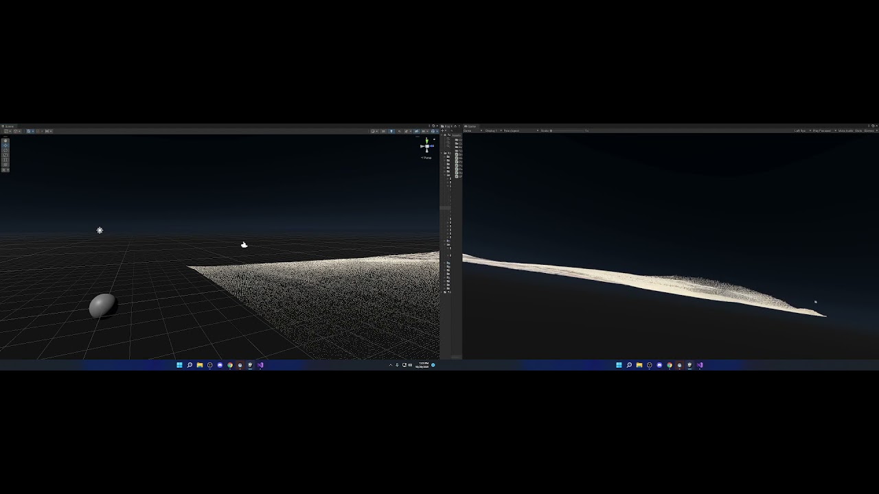
https://twitter.com/EmilMeiton/status/1432823877831479298?t=goY6KjYMfptqRYDYyEWb9Q&s=19

As a follow up to this tweet I reused the same array of positions to do soft shadows on terrain! It's an awesome feeling to see this running with 60fps on my phone. #indiedev #madewithunity https://t.co/yJy02yQqhk https://t.co/e8z0DQd2iM
Mobile games right now. I spent some time on an internal engine but right now it's only unity :)
On which games do/have you worked on?
(as in working with an internal engine. Not creating one)
I'd let that be a secret. Nothing too exciting
Oh ok
But day to day usually means handling communication between artists and programmers, helping out with pipeline and tools. And if I'm in luck some fun shader stuff
Among other things
Are you looking for work yourself?
Im still in high school
Nice. Hope you're having a better time than I did at that age :)
Ha ha... probably not
This is cool! It reminds me of this:
https://twitter.com/klemen_lozar/status/1136504201029259267

Poor man's metaballs. I should be working on game systems but I'm making some new tech AGAIN. Hoping to use this for a new enemy type #unity3d #gamedev #indiedev https://t.co/XmF4fXi9uM
Likes
748
Hang in there! 😉
xD
Oh yeah I saw the end result of that. Super creepy stuff :D
My result looks different ;-;
Could you help me again?
sure.., post a pic of what your node-tree looks like


This one is yours
oh
i think i switched the in and out values on the remap
sorry xD
thats probably it
oh a vector2 would probably be cleaner. Didn't think of that 🙂
the difference would be that a combine node is a bit more flexible. But in this case we only want a vector2 output so :/
oh so its a universal vector?
nah I'd say it's just a more flexible way.., there's no "universal" vector in the generated code per say
I'd suggest not using the combine node considering the vectorX nodes do the job but more purposefully
whatever is easiest to comprehend I guess
oh ok
sry if i explain this in a weird way. problem is that the blit of the post processing is not really ez to understand and deal with if make use of this line in my renderpass: "m_ScriptablePass.renderPassEvent = RenderPassEvent.BeforeRenderingSkybox; ", nothing gets rendered. (no tutorials on the web on this topic). thats why i done it like in this post: ````"The key is to use 2 cameras and a render texture as an intermediate buffer. The first camera uses a custom script to WaitForEndOfFrame to capture the frame into the render texture. The second camera then uses a custom ScriptableRenderPass (before post process) to blit the render texture into the 2nd camera for the final post process. I'm using shader graph to do some specialized processing with the render pass and allowing the 2nd camera to apply post processing afterward. Though one could configure the same setup so the 1st camera renders post processing and then the custom render pass does the extra post processing on the 2nd camera."``` https://forum.unity.com/threads/7-3-1-renderpassevent-afterrenderingpostprocessing-is-broken.873604/

Unity Forum
I want a custom render pass to be executed after integrated post processes.
But it turns out there seems to be no way for me to access...
and now i have the z-buffer transparent problem. https://answers.unity.com/questions/609021/how-to-fix-transparent-rendering-problem.html
Unity is the ultimate game development platform. Use Unity to build high-quality 3D and 2D games, deploy them across mobile, desktop, VR/AR, consoles or the Web, and connect with loyal and enthusiastic players and customers.
yo guys I am new to shader graph and currently experimenting with it , so I want to know how do I create a moving effect texture using graph

To create moving textures you generally want to use the Time node. Multiple delta time by the output of the UV node to get UVs that change over time. Then feed that into a noise function or whatever else you are making a texture out of to get a moving texture. Finally, connect the end result to the Albedo output in the PBR master node show the texture on the model.
you could possibly write your materials to be stackable (with blending modes that don't completely override the previous pass) and then add them to the material array through code
Yeah it's weird that they obscure it like that
is it worth the 80 bux? https://assetstore.unity.com/packages/tools/visual-scripting/amplify-shader-editor-68570?gclsrc=aw.ds

Get the Amplify Shader Editor package from Amplify Creations and speed up your game development process. Find this & other Visual Scripting options on the Unity Asset Store.
Non-artist and solo dev here, I made this protagonist model and I think it looks wrong right now in the the default shading/lighting of the built in render pipeline. So I am looking for some art style advice. Got any suggestions on what type of shader might compliment this model? What pipeline would make that shader the easiest to implement and tweak?

Totally unlit / shadowless is one option I'd try
I can't think of stylized shadows that wouldn't look weird on a blocky model like that
I do think it kinda looks funky with unlit/shadowless but this does seem like the right direction. The style is based off of a game that is all unlit/shadowless after all. I will roll with it and see what happens as I make more assets.

I definitely appreciate the advice. It helps with the decision paralysis.
I think adding some emission to make certain pixels look like lights would be fitting. But also, just go on google and search for images of different game styles and find something that speaks to you.
@wraith inlet Is there anything that this reminds you of that I should look at? This style is mostly just me ripping off Pineapple Smash Crew. I can't think of anything else that looks similar.
Hello. I have a simple URP Lit Shader Graph where I haven't changed anything except the emission value. I have bloom active in my scene, setting the emission color to pure white and increasing the intensity of my bloom shows it's having an effect on the material
The expected behavior would be that I could increase the intensity of my Emission in the shader and it would increase the intensity of the bloom effect, but there doesn't seem to be able noticeable difference increasing emission intensity


Nevermind I believe it's an issue with my scene settings and not the material, since it works fine in builds
Hi,
Could anyone help me understand the use of Sampler State Node in Shader Graph? Is it a good practice to use one SS Node to as many textures as possible to reduce samplers count? Because I'm hitting 16 right now.
ShaderGraph 12.1.0 has this bug ?
I Have a shaderGraph with SimpleNoise and subGraph
The subGraph also have SImpleNoise, Then compile error

He ho. I created a custom lighting shader but anyway I maybe found a bug while cleaning my graphs up. When I put my nodes into a subgraph my shader does not work anymore.
But if the nodes are in the shader instead of the subgraph it works.
Is this a bug or do I something wrong?

hey dudes I'm making a shader graph for a particle system and I'm struggling to give my vertex color an intensity
I want the Color Over Lifetime to affect the color, and to pull the intensity from that color. Is there a way to take the color and convert it to HDR?
Hey there, would it be possible to mix this shader https://pastebin.com/Zk4HJ4tf, together with the standard (specular setup) shader? I really like the look of the specular setup shader and I'm using it, although whenever I select an object I'd like to highlight it. The shader above gives the object an outline, although it doesn't look as good as the standard specular setup shader
I was wondering if this was quite easy to do, because I'm not very experienced with writing shaders 😕
is there a way to make a shader graph not be affected by an object's UV map?

Anyone know of a list of VR Helper functions for shaders? I have an issue where my ProceduralDraw (buffered data) moves to another location when a UI objects enters into the scene. Not sure if its a matrix problem, projector or what... but I wanted to study some of the VR based code that is required for the shader, and I did look on the Unity Docs, but there wasnt enough detail - ex problem https://www.youtube.com/watch?v=KGWdH9ABV7o
Objects can have multiple materials. And materials are shaders + settings.
So use the standard shader, and alter the other one to just do the outline part.
Don't use the UV's?
How do i not use the UVs
Use something else. Whatever it is that you want to use.
But how do i use anything else
hello!
im not familiar with graphics so i might be off here: im wondering how was inscryption graphics(in the 3d world) made? could it be some sort of shader that alters the graphics to be pixelated? or something else?
UV's are used to sample texture maps.
Yes
Unless you invent something else on your own.
Bro are you fr
Like triplanar mapping, which uses world-space to map to textures.
Instead of UVs
Is there anything like the blender's object mapping?
Always found this very helpful with weird stretching on objects

Specifically talking about generated and object
UV just uses the objects UV map
So you want the "Generated" version?
It reads a little vague, but it sounds like if you take an object bounding box, and calc each vert's position in that, you can generate a UV as a % of the box, but I'm unsure. I'll look for more details on their formula for "generated" for you.
Here's the "generated" version explanation as best I've found so far: https://blender.stackexchange.com/questions/23173/how-do-texture-coordinates-work/23174#23174
As for "object":
IDK, but here's an interesting spherical mapping using the object coordinates as set in blender. So you'd save those to the UV's I'd guess and then calc in the shader:
https://blender.stackexchange.com/questions/160973/generating-a-uv-map-from-object-generated-texture-coordinates
@stable flare
And yes, I'm "fr", are you?

Blender Stack Exchange
I'm trying to map planet textures on spheres, and the maps are Equirectangular. I'm initially mapping the textures to the spheres by using "object" generated texture coordinate input as the vector ...
Blender Stack Exchange
How exactly to texture coordinates work? I know they are represented by vectors, but how does a vector store texture mapping information? How does each type of texture coordinates work and what are
You can calc anything in the shader, and feed it to a UV coordinate. It doesn't even have to be 0 to 1 if you have wrapping enabled.
That would be you, programming.
How to achive colors&lights like in this game https://play.google.com/store/apps/details?id=com.hutchgames.hilldash2&hl=pl&gl=US ? Any advice where I should start looking?

Zapalić silnik do walk off-road! Wyścigi z modernizacji szybkich pojazdów
If someone has 10 minutes can you PM me? I have a shader that changes my skybox to a new skybox but I wanted to also change the color of the skybox.
Hey I am totally new to unity and I have a question about something.
How can you go from this

(default graphics)
To this


Here are just 4 examples, but how would you? Does it have something to do with the shader? What do I need to do to make the game look like how I want to?
I have been pointed here
Looking to change the atmosphere thickness on my skybox as it becomes day/night, any ideas how to approach this?
Is it possible through script?
you would need to download the build in shaders and modify the shader to expose the variables for the atmosphere thickness. Then you can change it via script
Ah okay right awesome, thank ya!
I am having an issue with URP shader graph
Transparent shows black in new unity Version
Anything wrong?

Wdym? The screenshots below just have a complete scene with different objects. The one from your editor has just the standard cube. Is there any other difference?
I think it might have something to do with the sprite renderer. Does it have the same effect on a regular mesh renderer?
May be. if I change canvas render mode to -> Screen Space - camera transparent is working but, not with overlay
Ah, sorry, I mean to say Image/canvas renderer, but yeah.
oh ok. it was working with unity older version(just one version below)
Sprites are always screwy. Grrr.
And I'm no expert. Should work with alpha blending if that black is pure black (0) plugged into the alpha. You should try the sprite mask too.
You could try clipping (discard) the pixel if it is black. That would involve a conditional and a discard.
Cool that should work. but need an alpha as well for other shapes. so I have left with one option, change canvas renderer to Screen Space - camera
I was referring to the graphics not the objects.
What exactly about the graphics is different?
You need the basics first. Shaders and materials are basically the same thing.
So start slow, use (and make) materials with the standard shaders, get to know them. They can give you all sorts of lighting and colors and effects. Get to know the particle systems, and sprites, and such. Once you figure out how it all works, THEN you can get into customizing and making your own shaders.
But if you start with shaders first, without a foundation, you're going to get blown out of the water.
The standard shaders and lighting systems can give you a TON of stuff right out of the box.
Unless you need some very specialize effects...but then you still need to know the basic stuff to pull off the customization.
2 cents.
Oh that's a good idea, thanks
The other way, that I assume you were trying to do, is by basically duplicating a standard shader, and then adding outline to it.
You didn't say what pipeline you're working in. If you're in the built-in pipeline, you could try using a Surface Shader since that will generate lighting similar to the standard shader.
But adding outlines to objects is a black-art and a large topic in and of itself, often requiring multiple passes depending on the technique and desired effect.
Here's an interesting article:
https://alexanderameye.github.io/notes/rendering-outlines/
and another:
https://bgolus.medium.com/the-quest-for-very-wide-outlines-ba82ed442cd9

Different techniques for rendering outline effects.

i'm using this to color a procedural terrain by height, but how can i add textures to this??

i'm really new to this
Sample Texture 2D node and link the output to the lerp
thank you so much!
I have a question: what is a PBR graph, and can it be used in 2d? If not, is there some sort of equivilent?
PBR = Physically Based Rendering - it's a lighting calc that is more complex but more realistic. Came about starting in Unity 5.0.
This is more expensive (and modern) than were other simpler techniques that didn't do energy conservation.
As to 2D, I kind of doubt that the lighting is PBR, but I'm unsure on that. However, there are quite impressive results with the 2D render using things like normal maps and various 2D settings:
https://docs.unity3d.com/Packages/com.unity.render-pipelines.universal@7.1/manual/2DLightProperties.html
2D renderer is used on sprites. See:
https://docs.unity3d.com/Packages/com.unity.render-pipelines.universal@12.1/manual/ShaderGraph.html
How would I make the islands green with brown shores? Sorry for the lq image, Ill post a higher quality one if someone needs it.

Hello guys I have a simple problem,
I was following this youtube tutorial, after the step (1:29) my plain becomes pink (broken) can someone help me fix this?
https://www.youtube.com/watch?v=1tHhGa7gi8o&t=55s

In today's tutorial we're going to see hoot create 3d sprites starting from 2d sprite sheets in Unity and how to animate them using a little bit of shader graph and C#.
The sprite sheet used in the tutorial: https://opengameart.org/content/pixel-art-character
Check out the game I made this effect for: https://punkpebblestudio.itch.io/five-step...
What render pipeline are you using?
I did some more digging, and tried the Universal RP, it was almost fixed but then this happened.
According to the tutorial I should be getting transparent BG instead of white (2:55).

Did you set the texture settings as he does in the beginning of the tutorial?
I think I did, from sprite, shaders, and materials.
The only thing that is different is that I added Universal RP.
Take a screenshot of the texture asset.


Does your texture actually have alpha?

Win10 bg is dark, so uhh thats why it looks like its not transparent.
In the texture preview there should be buttons for viewing different channels. Try switching to the alpha channel and take a screenshot.
Im sorry sr dlich, im quite new to Unity. I dont know where to find the "Texture Preview" is.
Just below that texture import settings.
Below the inspector that you shared on the first screenshot
can I use aseprite instead? to screenshot my current sprite?
Aseprite?🤔
Ah, an external editor? No, I want to see the alpha channel as unity sees it.
ohhh

No, here's what I mean by the preview windwow:


click the A button

Okay. I guess the alpha is there
What does that mean sr dlich?
Alpha defines the transparency of the pixels
So I guess it's something about your shader
I do think so too Sr Dlich, I think I have to use another shader.
Thanks for teaching me things sr dlich
You probably need to set the surface type of the master node
to transparent
@tall cliffActually, nevermind that.
I think you just skipped a step from the tutorial:


If something does not work for you, make sure to rewatch the tutorial and confirm that you didn't skip anything.
Hello, I am looking for a shader that can increase the brightness of my sprites (make them whiter as it increases)
Wave Texture to Color Ramp to Base Color
Use the color ramp to get colors that you want
Hmm how would I change a value of a shader at runtime? I know I can change it for a material, but I need multiple materials, so I can have different base textures for different objects... stlil want to change my _PlayerPos value for all of them though
You can use a global shader property (set to non-exposed if using Shader Graph, or in code, don't define it in the shaderlab Properties block but still use it in cg/hlsl block the same way you would for a regular property). Set it through Shader.SetGlobalVector("_PlayerPos", playerPos);
Works, thanks
Is object position in shadergraph just the coordinate relative to the game object's center? (and is it pre or post Scale)
I see a height calc in that node graph.
Use the height to determine the color.
So a gradient lookup relative to some height value for the islands. Higher would be green (maybe move to brown/grey rock, or white snow up really high) and the low/water level would be sand colored. All based on height range relative to water level.
If you're referring to the Position node set to Object space, then yeah it's coordinates relative to the object, but it's origin, not necessarily center. Specifically it's the vertex positions directly from the mesh (interpolated if used in fragment stage). The pos/rot/scale of the Transform component isn't taken into account, that's for World space.
Hmm
Trying to figure out why my shader behaves differently for different objects xD I modify the World position but then Transform it back into object before I plug it into the Vertex stage's Position node

It's supposed to bend downwards the further it's away from the player on the Z-axis... and it does
but for some reason different objects bend differently :D
Like without the bending

but then with it, the cube bends too much and sinks through the ground

It's okay if the player is close to it, so I guess maybe the scaling of the object messes with the Y-offset (that creates the bending effect) somehow
Is the ground and cube is using the same material? (or at least same bending property values)
Strange. I've used a similar graph before and didn't have this issue. Not sure what would be causing it

hm
they're probuilder cubes? Not sure if that would affect anything
Oh I'm dumb ¬_¬ was sure I set them to the same and from just looking at it they looked the same, but one was set to 1.6, the other 1.8
Whoops 😅
Might be a good idea to set all the bending properties globally like the playerPos so they always stay the same
Yeah, probably. I only made them exposed because I figured that's the way I can change them :P
how do i put the diffuse, mask, specular, normal, emission textures into a material, i have try to do this for a lot of time
How could I flip the texture Y using shader graph?
When you sample the texture, put in 1-uv.y as uv.y
anyone know why my shadows are glitching out like that when i change the rotation of the light?

the rotation is smooth
yet the shadows are not


urp settings

mesh settings
https://cdn.discordapp.com/attachments/900380950083534888/904406697848754226/unknown.png
Someone? Help? All my UI shaders are fucked. how do I fix it?

Huh. Unity allegedly calculates shadows every frame. And you have a 4096 resolution on your main shadow texture (but 1024 on the additional lights).
Is that your main light you're rotating?
yes
also changing the resolution for additional light does nothing
but changing the main light res does change it (the shadows)
Yeah, expected if you're rotating main.
What changed?
Try not rotating for a few frames.
Like rotate some every 4 frames or something. Does it still jitter?
You have real time lighting enabled, so...IDK.

delta time is frame time. So you're not really getting time of day.
:D
I use a clipping mask in the Unity terrain shader to hide the terrain where I have roads.
But this seems to work only for my main camera.
As you can see in the SecondaryMainCamera window, here I still have Z-fighting between the terrain and the road.
How is that possible ?

@violet boughwhat changed when you modified the resolution. I assume it still jittered.
yeah :/
Your var rot here is a Quaternion right? It probably doesn't make sense to then alter .x directly like that. You probably want to use .eulerAngles instead of .rotation
it also messes it up a lot
hmm
i'm gonna try that
this is the first time i'm dealing with unity rotations in 3d
so kind of confused
hmm well
i tried that, but it's still the same
also upadting every 4th frame doesn't change it, just slows it down
the glitches are most noticable on long shadows
e.g. when the light is just above the horizon
Cyan is correct. You shouldn't modify the quaternion like that. I missed that. I saw that you assigned a new one with euler anges.
But you got the angles from the borked quat.
I'd probably do lightTransform.rotation *= Quaternion.Euler((TimeOfDay - 6f) * 360f/24f, 0, 0); (wait, maybe just = instead of *= since you are changing TimeOfDay)
You already update them when you assign the new quat in:
lighttransform.rotation = Quaternion.euler(....)
But you got the values from the old borked quat
How can I use shader keywords in Shaderlab code? 🤔
*= ?
Ok
Let me check
So... Can I use them in shaderlab
?
Can you understand whats I am saying
?
Sorry yeah, just = makes more sense. *= would work if you wanted to rotate the existing rotation with the quaternion instead of replacing it.
You can only use keywords in the cg/hlsl section of shaders. It won't work for the ShaderLab sections. Sorry, thought you just meant shader code in general at first.
Ah sad
Then
Any method to convert it?
If can convert it
Then ok
What are you actually trying to do?
I have a shader which has more than one keywords
But one shader
No you will not understand
Can I dm you?
I want to show a preview picture also
I don't do dms. You can post images here too though.
you can create a thread @echo solstice
Is it safe?
No
My code is valuable
I can't share it public
😂 this is precious
Yes
Really precious
:)
Let me explain short
Same shader
But separated keywords with separated function
For an example
example.shader it has Maintex, lightmap, Matcap, Decaltex like that 4 tex2D input in properties. But I have 2 codes ( shader lab) I shaderlab code include Maintex & lightmap tex feature and other Shader lab code include matcap & maintex
I want to put all 4 features in a single shader and use keywords to enable each one
Like merging 2 codes into 1
The link Cyan gave you shows you how to do multiple variants to "enable" or "disable" options in shaders.
The #if directive in the CG/HLSL part works.
// Code here is compiled for variants that are used when the keyword FEATURE_FOO is enabled
#endif```So
He told me
That I can't use that on shader lab
I don't use hlsl
And not familiar with hlsl shader 😐
I also have read this article not only this all the articles of unity
To solve this
Or another solution
Is there anybody who knows to convert shaderlab to hlsl
Then ok
Syntaxes?
You can get the output from shaderlab (it is a code generator) and then dig through it. There's multiple variants, and it is a large file, but ...well...that's how you do it.
There's a "view generated code" on the shader in the inspector panel IIRC.
That will show you the vert/frag style of shader generated out of shaderlab, with included passes for lighting/shadows.
Thanks, will try it out
Yes
So I've been trying to convert some of my shaders to shader graph but I have no experience with neither shaders or shader graph itself. Any help would be much appreciated... This is one of the shaders I'm trying to convert
Shader "Custom/GroundShader" {
    Properties {
        _MainTex ("Base (RGB)", 2D) = "white" {}
        _Lightmap ("Base (RGB)", 2D) = "white" {}
        _Tintmap ("Base (RGB)", 2D) = "white" {}
    }
    SubShader {
        Tags { "RenderType" = "Opaque" }
        LOD 200

        CGPROGRAM
        #pragma surface surf Lambert

        sampler2D _MainTex;
        sampler2D _Lightmap;
        sampler2D _Tintmap;

        struct Input {
            float2 uv_MainTex;
            float2 uv2_Lightmap;
            float2 uv3_Tintmap;
        };

        void surf (Input IN, inout SurfaceOutput o) {
            fixed4 c = tex2D(_MainTex, IN.uv_MainTex);
            fixed4 lightmap = tex2D(_Lightmap, IN.uv2_Lightmap);

            if (c.a == 0.0) {
                discard;
            }

            if (length(IN.uv3_Tintmap)) {
                fixed4 tintmap = tex2D(_Tintmap, IN.uv3_Tintmap);
                c *= fixed4(tintmap.bgr, 1.0);
            }

            o.Albedo = c.rgb + lightmap.rgb;
            o.Alpha = c.a;
        }
        ENDCG
    }

    Fallback "Mobile/VertexLit"
}
Is this hlsl?
That's a shaderlab surface shader.
Looks like vert/frag to me.
Unless you see a pragma
#pragma surface surf .....
?
What happens if you try the #if directive in that shader?
I want to try
But
I don't know
Where should I put that?
Position?
Wherever yo u want it in the code to do what you want. I mean, there's no way I can tell you unless you have a specific "I want this code if this, and that code if that".
But HLSL shaders understand #if directives. Unity will define the directive for the keyword.
like :
float4 myColor = float4(1, 0, 0, 1);
#else
float4 myColor = float4(1, 1, 1, 1);
#endif
Aah
it looks like when a camera uses a replacement Shader, it completely ignores holes created by using the clip() function in another object's shader and renders these objects entirely as if there was no hole. Am I right ?
Thams if I have more problems I'll contact you
If the CAMERA is using replacement shader...it renders them all with that shader. So unless that shader has the clip function, there is no "other object's shader". There's only that replacement shader.
IIUC
In the shader used by my Unity terrain, I have this function, and the main camera renders holes created by the clip function as expected :

I've now found out that even when i just modify the Z rotation of the main light, it recalculates the lighting and it jitters
even though the Z component does practically nothing :/
so it's something to do with the actual lighting settings and or the shaders
sorry for interupting

@meager pelicansee here : the Z-fighting appears only on the SecondaryMainCamera, because it use a replacement shader
np, you were here first.
So what do you mean by "i just modify the Z rotation of the main light"?
Remember, you don't want to modify quaternion components. You make a new one. Right?
i mean in the inspector
OK
It looks like you were wanting to rotate around Y axis anyway.....

lol OK.
But why modify Z rotation? Is that what you want to do?
no, but now i know that the problem is not to do with bad quat. updating
IDK the current directional vector of the light anyway.
i guess i'm gonna try messing around in the settings because nothing else makes sense
rotation of the light should work.
What's your current rotation code, now?
Post it using three ` wrapped around it, so I don't have to retype it all from an image.
ok
It's small enough. Or use pastebin or something.
float y = (TimeOfDay - 6f) * 360f / 24f; lightTransform.rotation = Quaternion.Euler(0, y, 0);
i've changed it to y, because i'm gonna be making the light behave like the a real sun later, doesn't matter
but i believe this isn't where the problem lies
OK, if it's a "real sun" you have to either rotate your "planet" or you have to go to a Earth-centric universe and rotate the sun around the planet (easiest).
So I'd do a https://docs.unity3d.com/ScriptReference/Transform.RotateAround.html
but my problem is not the actual rotation
Followed by a look-at.
because for some reason,just a small change to the rotation has a large impact on the shadow in chaotic ways
Oh, I see what you're saying....but....unless you're actually doing what you want to do in the first place, the discussion is academic.
So my shader has a property _MainTex ("Base (RGB)", 2D) = "white" {} and in my graph I've created a property with the same name however when I set that shader to my object it doesn't set the texture
any ideas?
property is marked as exposed

You need to change the Reference to _MainTex too. The "Name" in Shader Graph is just for display purposes, it's basically equal to the "Base (RGB)" string in the code.
this is what I'm trying to do

Oh.. so it's the other way around? I thought the name was the property name like in the shader code.... thanks!
What would be the node needed in shader graph in order to flip my texture Y?
Tiling and offset node?
Does anyone know how to make simple distortion effects work on transparent objects? I can only get it to work on opaque. I’ve followed at least 3 different tutorials and all of them only work on opaque. Any ideas?
I’m working in URP.
@echo zealot this looks relevant
https://www.youtube.com/watch?v=atPTr29vXUk

In this video, we are creating a Distortion Shader using Shader Graph in Unity 2019!
Download the project here: https://ole.unity.com/DistortionShaderProject
Shader Graph in Unity 2019 lets you easily create shaders by building them visually and see the results in real time. You create and connect nodes in a network graph instead of having to...
anyone know how to convert the Vertex Color node of a shader graph to an HDR color?
@sterile sigil thanks for the tutorial, but unfortunately that technique only distorts objects that are set as Opaque. 😦
The color node has an HDR option on it....if that helps.
https://docs.unity3d.com/Packages/com.unity.shadergraph@10.2/manual/Color-Node.html
thanks mate, what I need is to somehow combine that color's intensity with the input from Vertex Color
I've tried blending and adding, idk nothing seems to work as I want it to
You need to be specific as to what you're distorting. Verts? Backgrounds?
Quads with materials set as transparent. I’ll send a screenshot.
Have you tried a multiply?
In other words, an intensity of 2 would be 2 times greater values.
However, I think HDR colors use some kind of power function or something, or maybe that's just the inspector's way of dealing with it.
So you want to distort the background behind the transparent quads?
If so, you need to use the scene color node, and enable it in the settings. Otherwise you'll just get grey results.
I have distortion working well. But any material set as "transparent" gets ignored.


A - Shows the quad with the distortion shader.
B - Shows a quad with a "transparent" material on it.
C - Shows the distortion working on a sphere with an "opaque" material on it.
"Ignored"?
What about "invisible"?
Change your distortion shader to multiply the color by 2, see what happens. Just for fun.
And check what you're putting into the alpha channel.
Also additive black is invisible.
in case you're getting 0's somewhere.
For this effect I followed this tutorial by Gabriel Aguair.

Let's see how to create a Heat Distortion effect in HDRP and URP. Also known has heat haze or air distortion is a visual effect used many times in games to convey the feeling of something so hot that it distorts the air around it or to create a mirage.
00:00 Intro
00:38 HDRP - Screen Space
05:12 HDRP - Normal Based
06:32 URP
15:34 End Credits
...
He mentions at "11:46" that the downside is that this trick doesn't work with transparent materials.
I've looked for a couple days and can't seem to find one that does. 😦
Well.....
The scene background won't have transparents in the scene color.
The scene color node grabs the background from the OPAQUE pass.
Yeah for sure.
But I thought you said it (your distortion quad) won't work in transparent.
That's different from "It won't distort transparent things".
Apologies, your second sentence is what I meant. "It won't distort transparent things."
There's work-arounds.
Cyan is typing too...so we'll see if he's responding to this.
Yeah, the scene color node uses the camera's "opaque texture" which is captured after rendering opaques and won't include transparents. If you want to distort them too, you'd need to do something like rendering the distortion values to offscreen render texture (additively if you want them to stack with other distortions), and use that in a blit render feature to apply the distortion to the render in the after transparents queue. It's similar to the techniques explained in this video : https://www.youtube.com/watch?v=xH5uUfeB2Go (but that's built-in RP stuff)

Get the Shaders for this Video here ➜ https://github.com/Broxxar/PostProcessDistortionFX
Support me on Patreon ➜ https://www.patreon.com/DanMoran
Follow me on the Twittersphere ➜ https://twitter.com/DanielJMoran
Extra Links:
Environment Art ➜ https://www.kenney.nl/assets/nature-pack-extended
Character Art ➜ https://www.kenney.nl/assets/3d-chara...
Oooh 🙂
I'll look into and give this a shot.
Thank you both @meager pelican and @regal stag for the assistance. I'll let you know of my discoveries.
There's probably other ways too.
Like camera stacking.
Or hand-editing shaders, to use a type of grab-pass (not sure on that one).
Which of these? Figured it out, I had to apply the tiling and offset to the texture uv

So now I have this and it works. Now everytime I flip my texture scale, either X or Y, it becomes invisible... Any clues?


it’s the small details like those patterns on the ground that interest me
I wonder why no one mentioned it so far, but you're not using the standard shader for the ground, do you? It seems like the shadow calculations are not regular either. Are you using some kind of noise when sampling the shadows?
Just disable culling?
According to the docs for 2020.3 say the Procedural Skybox shader is supposed to have the following properties in the inspector
- Sun
- Sun Size
- Sun Size Convergence
- Atmosphere Thickness
- Sky Tint
- Ground
- Exposure
When I set a material the use the Procedural Skybox shader I get a different set of properties
- Sun Tint
- Sun Strength
- Atmosphere Tint
- Ground
- HDR Exposure
- Render Queue
- Double Sided Global Illumination
What am I doing wrong?
Either you're looking at the different version docs or using a different render pipeline.
This is my first project, how do I set the render pipeline?
I got to the docs from the help menu and the versions appear to match my editor
Guys, if I add a cube into the scene during play, and add a standard shader in Transparent rendering mode to this cube, shouldn't this cube be a little bit transparent?
slide the alpha, got it, thank you youtube xD
You can check the render pipeline in project settings - Graphics. If the render pipeline is empty, it's the built-in.
Yep, it say none
Then maybe the docs are outdated.🤷♂️
ok, I'll ignore it for now. It's frustrating not having a source of truth. Was trying to follow an online class and they were describing properties I didn't have in my shader. So I looked at the docs and the docs agreed with the video but not what I have.
I'd assume that 2019.4 matches what's written in the docs. The docs are sometimes late to update.
Most of those settings are in the Environment tab of your your lighting window...
No, I'm using a custom shader. I'm getting on the computer now so wait a minute and i'm gonna send it to you

Calculate Lights function:

Calculate Main light
#ifndef CUSTOM_LIGHTING_INCLUDED
#define CUSTOM_LIGHTING_INCLUDED

void CalculateMainLight_float(float3 WorldPos, out float3 Direction, out float3 Color,
        out half DistanceAtten, out half ShadowAtten) {
#ifdef SHADERGRAPH_PREVIEW
    Direction = half3(0.5, 0.5, -0.5);
    Color = 1;
    DistanceAtten = 1;
    ShadowAtten = 1;
#else
    #if SHADOWS_SCREEN
        half4 clipPos = TransformWorldToHClip(WorldPos);
        half4 shadowCoord = ComputeScreenPos(clipPos);
    #else
        half4 shadowCoord = TransformWorldToShadowCoord(WorldPos);
    #endif
    Light mainLight = GetMainLight(shadowCoord);
    Direction = mainLight.direction;
    Color = mainLight.color;
    DistanceAtten = mainLight.distanceAttenuation;
    ShadowAtten = mainLight.shadowAttenuation;
#endif
}

#endif
IMPORTANT: I tried to just delete the dither and random noise and it still glitches out
so it's not the problem
Anyways, I'm 99% certain that the issue is related to the custom lighting/shader. It's unrelated to lighting/shadow settings. You can probably confirm it by switching to a standard shader.
Yeah well probably up to me to find out why :/
Looking at some of the functions(specifically GetMainLight) it seem kinda weird. Couldn't find any mentions in the context of URP - only LWRP. Which makes me wonder why that lighting calculation even compiles...🤔
I got that from a tutorial on a toon shader from ned makes games
Was it targeting LWRP perhaps?
Can you share the link?
✔️ Works in 2020.1 ➕ 2020.2 ➕ 2020.3 🩹 For 2020.2 and .3:
► When you create a shader graph, set the material setting to "Unlit"
► The gear menu on Custom Function nodes is now in the graph inspector
► Editing properties must be done in the graph inspector instead of the blackboard
► In Lighting.hlsl, change the line "if SHADERGRAPH_PREVIEW" to "...
Ah, it's a video. Can't watch it now, but I'll have a look later.
Can you disable the noise parts of your shader graph and record a video again. I was pretty sure it was related.
I'm not at my computer rn, but i tried exactly that and it produced the same jitter
Weird. Because that's what introduces randomness into your shadows. Otherwise they'd look like regular shadows. At least if I get it right.
Just now occured to me that it's targetting URP, since it has unlit shader graph -> those are only available in URP
and he downloads URP package
Yeah, since it says in the description, that it works in 2020, there's no way it targets LWRP. That's not a concern anymore, but it's weird that I couldn't find the function in the source code.
If you’re talking about my picture that’s because I just migrated to URP and haven’t fixed the models shader yet
Which node if I may ask?
I havent tried shadergraph unfortunately
But from this answer, seems like you can access it from the cog/setting menu
https://stackoverflow.com/questions/60192970/double-sided-shader-with-shader-graph

Stack Overflow
I'm a complete beginner when it comes to shaders, I'm building a project and I need to use Shader Graph in it.
I would like to know if it is possible to render two different things on each side of a
Will try it, thanks!
Has anyone experience with light cookies in hlsl unlit shaders? Was happy to hear that Unity 2021.2 supports light cookies, but how can I get the cookie lighting for custom lighting?
Is there a way to 'build' an HDR color in Shader Graph? I'm looking to take the R, G, and B values from a color and add an intensity to use in the Emission slot.
I'm able to create a Color and set it to HDR and line that into Emission, but that doesn't allow me to change that color, which I'm hoping to do with the input from Vertex Color
Ok I've been posting this question here for a few days and I just figured it out so I'll type up the answer
Using Custom Vertex Data from the Particle System allows you to setup a Color stream. This stream is going to take info from the Vertex Color node, which is default.
Another way to approach this is to run Custom Data from the Particle System as a Color, rather than relying on the Vertex Color. This allows you to treat the Custom Data in the Shader Graph as just another UV input, but deal with it in the Particle System as an HDR color under Custom Data > Mode : Color
I'm very new to Shaders in general, but is it possible to add two different textures to a plane? Like a sign, or a book page that are different on each side?
It is meant for VR, so it would be a nice way to instead having two meshes on top of each other
you certainly can. I'd recommend handling it in the shader rather than having multiple materials attached to an object
I'm more well versed with Shader Graph. To accomplish this with shader graph, set up your model with proper UVs, create two textures that fit those UVs, and set the graph up like this:

The idea here is that you're taking 2 texture inputs, and blending them together before applying it to the base color. What I've done here has your plan in mind, of mixing text on top of a page texture. I used a Blend Multiply node, with the opacity set by the alpha of the text texture. This would let the text only get multiplied where it is non-transparent. A variety of details in how your images are set up change how exactly you do this, but this is the general idea
I assume you're trying to change that text image proceduarlly to simulate page turns in game?
If it's always just going to be a static image I'd recommend baking the text into the page texture image, but if the plan is to change it on the fly then go with a shader solution like this, IMO
I think what he wants is a bit simpler: render different textures on each side of a page.
Apparently there's a "is front face" node that you can use to determine what side of the plane the pixel is on.
@vagrant kraken have a look at the last reply on this page https://forum.unity.com/threads/shadergraph-make-shader-lit-on-one-side-unlit-on-other.607015/
Unity Forum
Hello! I'm trying to get an effect where one side of a double-sided shader is lit and the other is unlit. I can't find anything in the Master Node...
Thank you guys for the material! I'm just not quite sure if that is the case here🤔 I don't necessary want to render one texture on top of another, but rather have one texture on each side, like in this example from HL Alyx:


Yeah, exactly what I said, no?
Here
better example, but yeah, I'm not sure, this polaroid picture is a solid mesh, not just one plane


There are 2 ways to do it:
- Have a 2 sided quad with each side uv unwrapped separately
- With a shader that renders both sides. The link I shared above deals with that method.
Yes, thank you! I will try to follow the link and get help from colleagues if I'm stuck👌
So I switched from unlit to sprite. Now it’s just flat out multiplying over the entire sprite, how do I stop that?
@honest scroll can you show an updated image? not sure what you mean by that
I see your original image, what is the behavior after changing to sprites?
If the the blacked out images(that change colors based on how you rotate it) is vanilla unlit, this is sprite.

mk, can you show me the inspector for the text sprite import?
or maybe the text would be better handled in game anyways? Using TextMesh or something?
Text boxes

and the 'Silver' material is the Unlit shader
can we see the import for the 'Text Bubble New' sprite?
And the actual text.

Sprite, but it was converted from unlit, yes.
I have a hunch it's related to the sprite import moreso than the shader
It's imported as a Sprite, what's the max size?
The import settings if switched back to unlit.

You mean the image used? Yep! that's a sprite.
so what I'm looking for is the Inspector panel if you select the Sprite in the Project panel
Which for that.

change max size from 32 to something higher
whatever suits the image size
I assume it's not a 32px square image
Well, the thing is that it is.
ok, can I see that image I guess? how are you typing letters into a 32px wide frame
one letter is going to be about 6px at the very smallest
Well, I split them into their own segments in the editor to make it tileable.

But like I said, I think that's not the problem. It changed to green after rotating the object on the X axis.

A bit on Y

And onto the opposite side.

mk sorry I was focusing on the text too much, now gonna need to see that Text Box sgraph
before that though I guess what is motivating the custom shader over a normal UI one?
Which is weird because it looks fine in scene view.

It's color coded. I need more colors for not just the player(fabric) but also the team(metal).
that makes sense
what type of object are the sprites on? they're not meshes are they?
just UI transforms?
And the graph.

Ui transforms.
graph settings
As seen here.

if you change the render face, does the issue invert?
does the issue resolve if you switch from Transparent to Opaque, and make use of the Alpha Threshold rather than typical alpha blending?
is that Canvas containing all of these images set to Screen Space?
I'm just mentally going down the list at this point, unsure which if any of these is the solve
Here's backfacing.

well that's new


I personally say it's taking color from the coordinates of the object than the texture.
hm. maybe it's something with how you're using Vertex Color?
I don't think using all 4 channels of the vertex color to factor that Lerp is correct, unless I'm misunderstanding something
another idea, try changing Depth Test to Always in your Graph Settings
Tried all those, still black.
what did you do with the Vertex Color, and why is it involved in the first place?
Likely you want to change the color from the Inspector of the UI element? I would suggest using that color as the color you're going to blend, not the LERP factor

maybe just use the Alpha, as I think that's defining the mask you wnat
I haven't been completely following this convo, but the problem is likely that Shader Graph just doesn't properly support UI currently. It might be trying to render multiple/all the passes from the generated shader, in this case with the DepthNormals pass on top, hence resulting in different colours when rotating the quad.
The vertex color is for the player color, so I wouldn’t use that much materials but use more vertex colors.
It might be so, which is stupid.
Yeah, You could probably use the graph to generate the shader code and remove the other passes, which might fix the issue. (But then it's a separate shader so if you want to edit the graph you'll have to generate the code and edit it again)
Sadly enough.
I'm trying to create a fog-of-war for a 3d grid based game.
The camera can be moved and rotated freely, so I cannot use a render texture on a plane above the level to block unseen gridspaces.
I'm also not sure a stencil shader on a simple mesh would work either.
The gridspaces are all one object/mesh, so as far as I know I can't use layers to hide parts of the mesh either.
Can a shader be created to only display objects that are within a certain 3d space/mesh? (if I overlay a mesh overtop my grid for example)
Hey guys! I'm trying to create a shader graph to render my sprites.. It works but sometimes my character sprite will "poke through" ground. How could I avoid that?


its unclear what a fog of war effect would even look like without a fixed perspective camera, imo. If I drop the camera down to be parallel to the ground so that the camera is inside the fog, with "visible" objects in front of me and "fogged" objects beyond those visible objects, what should I see? If I can see through the fog in front of the visible objects, what gets rendered behind them? Just black?
This kind of looks like a sorting problem to me. Some information here: https://www.sunnyvalleystudio.com/blog/how-to-sort-sprites-in-unity

Learn how to sort sprites dynamically in Unity 2D according to their Y position to create an illusion of a 3d world in a 2d environment.
Either way, could we get an official response from any staff members on that?
That's for 2d sprites, we're using meshes for the ground and sprites for the character
We have sorting groups for cases like that
@wraith inlet To put it simply, I want "unseen" gridspaces to be invisible.
the easiest way is to 'lift' the sprite so it's always above the ground.
Shader wise, maybe you can decrease(or increase if UNITY_REVERSED_Z) clip space z position
There are a couple of approach I could think of...
- Stencil, but it's either show or no show, no fade between
- Using render texture on a plane, but instead of blocking unseen space, you use the render texture as a world space color(or alpha) lookup for every objects affected by fog
hello. i hope the question belongs here. if i use GL (low level grap. library), i always need to link Shader? (for example: draw a line)
Help appreciated

in short, top being the render i'm looking at in unity and bottom being a manual edit of what I want

Did you try it?
Let's say I have an integer with certain bits set to 0 or 1. And I pass that integer value to Shader Graph. Is it possible to retrieve the bit values in Shader Graph? It's ok if some math operations are necessary.
I think integers are converted to floats in shader graph which might make it harder
Could write a custom node. It seems like HLSL supports some bitwise operations.
Yeah, it seems like you can't pass an int into the shader graph, since it's not supported on some platforms, what you could do is convert a float to an int in the custom node and do whatever bitwise operation you need on it.
I was hoping it would be possible without bitwise operations, and I found a possible solution, just checking if it works right now
Mind sharing that solution?
Divide by the value of the bit that you want to check, floor, and mod 2
floor(value/(2^bitPos)) mod 2
How are you gonna get the value of the bit that you want to check then?
What's bitpos?
bitpos is the position of the bit you want to check (like the 2nd bit for example (0-based))
Hmmm... Either my math is wrong or it doesn't work for the value of 1🤔
Ah, actually it does.
Interesting.
Yeah mathematically it looks like it works, now I'll try it in the shader
Yes I always get pink line ... When I don't put shader or I do, always get pink line 
Well, then you got your answer.
But I didnt set pink colour 
ahhh, I guess that wasn't clear. Pink color usually means that a shader is missing or incompatible. I thought it was clear that if you get pink color, it means that you must use a shader...
But I used it and still got pink (I used unity one, not costume)
Was that shader compatible with the current render pipeline?
Oh I don't know right now, but I will check and try other ones
Any idea how to make shader so when object jump in fast velocity it will strech it? like inStarTrek?

Captain Riker leads a Federation fleet to assist Admiral Picard at the Synth Homeworld.
#StarTrekPicard #Picard
Season 1 Finale
Episode 10
Should be possible. Just pass in the velocity of the object into the shader and displace vertices along the velocity vector relative to their local position.🤔
Or you could do it the post processing way to stretch the whole rendered image
I'd be interested to have a look at the effect if you manage to get it working!
Thx for help 🙂 really. I have done The animation, is simple, for now i jut move it fast forward and disable render. Same for exit but oposite order, just need good VFX and Sound.
Iam not good at shaders. Will take me ages to figure out how to code your architecture.
So you decided to not do it via a shader?
Alright
Should be possible via the shader graph btw
Shader will be for that stretching. Particles for Flash
i can use velocity vector even if monovement is Animation driven?
you'll have to calculate it yourself. For example, based on the difference of position between the frames.
is is lit Shader or Unlit?
Depends on what kind of material you want. If you want it to be lit properly, then lit.
Mat should be a Ship Material i think
You'll need to replace the shader of the material you're using currently. What kind of shader are you using for it?
There is no Models with Meterials or Textures yet for any Ship. Currently Testing it with Default Cube 😦

Unity Learn
In this tutorial, we’ll create a Shader Graph to displace the vertices of a mesh along their normals by an amount controlled with procedural noise.
Yes, that's the first method.
Although the tutorial seems to be for the older version of shader graph.
yeah 😦
Well, it's not much different from in the latest version. You just have the vertex and fragment nodes instead of a pbr master node.
I think they should encourage people to use online shadergraph viewer like this https://shadergraph.stelabouras.com/
Kinda hassle to see what they're asking by just using words
Have u time to look at it? 🙂 Yeah i noticed PBR isnt there
Not not. Maybe tomorrow.
Sure 🙂
But try to do it yourself first. Don't just rely on people to do it for you.
You are right.

Try doing the math on paper too. What you have currently will displace all of your vertices the same amount, so there's not gonna be any stretching.
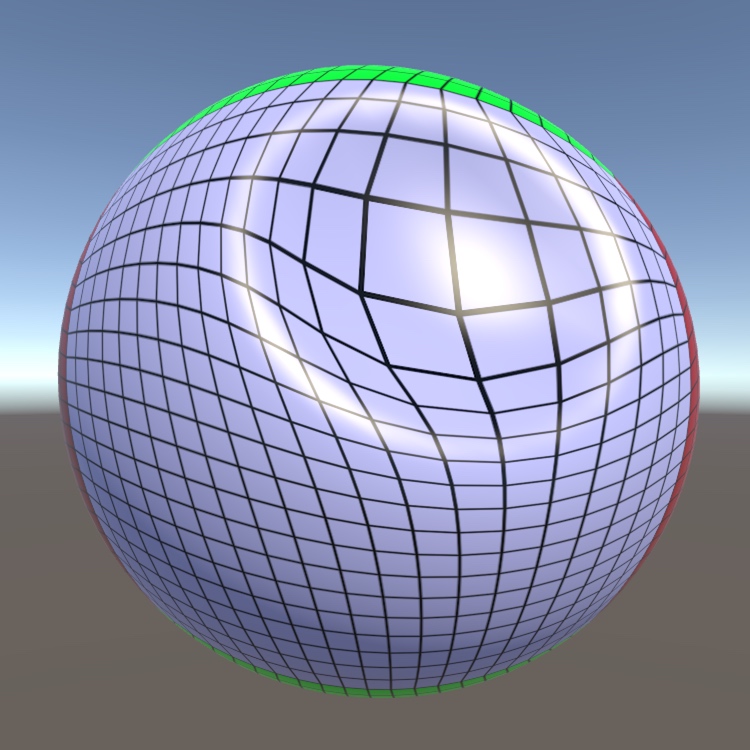
Hey guys 🙂 I am still trying to figure out how I can solve my rendering issues with my double sided sphere. I want to be able to look into the sphere through front faces and see the inside faces.
I am on Unity 2020.3.8f1 with URP 10.5.0 installed.
You can see on the left side that it's working as I intend it, the texture is showing through the hole and you can see the backfaces. On the right side however it's breaking apart for some reason I don't understand.
How can I solve this?
General shader setup:

Extra Pre Pass setup:

Even more apparent without the cube inside:

What about this approach
https://catlikecoding.com/unity/tutorials/mesh-deformation/
A Unity C# scripting tutorial in which you will deform a mesh, turning it into a stress ball.
For me is coding little better then shader graph, DK why
Possibly flipped normals?
That's another way to do it: editing vertex positions of the mesh via script. It's probably way slower than the 2 methods that I mentioned.
If you want it to affect the whole mesh or even several meshes that are more complicated than a sphere, it might kill your performance.
normals are fine
Maybe ask in the asset community? Is that "Amplify"? I'm not sure how precisely it matches the shader graph and what each of the nodes do.
Already did, just trying to increase my chances of someone knowing what's causing this 😅
If you ask me, the math in the graph looks weird. Like what's with that distance between vertex position and 1 0 0 vector supposed to do..?🤔
Ah I see. I'd expect it to be an exposed property.
What's responsible for rendering the inside though?
Culling is off and there's a prepass with zwrite on
What if you only render the prepass?
Is that the prepass?

If so, are you sure that you want to set it's alpha?
You probably should render the inside of the sphere as another mesh that's always behind the outside of the sphere in render order
Transparent single faces rendered from both sides in the same mesh will always fight each other for depth
When I activate "Alpha to Coverage" in the shader the technical side of things works. But I don't want those hard edges. Is this because it's basically turning it into non-transparent faces?
Yes, it's 100% opaque so it doesn't suffer from the problem
Any transparency makes faces difficult to sort for the renderer
Zwrite solves that problem but also stops all transparent faces being rendered behind any other transparent faces
So you wouldn't be able to see the inside of the sphere
I see, thank you
Is it possible to use GPU Instancing with Shader Graph? I'm quite new to vertex-fragment shaders but I have some experience with Shader graph
Is it not supported by default?🤔
Not sure, I've only been able to get it to work without using shader graph
Pretty sure it's supported for quite a long time. Just check Gpu Instancing on the material.
SG supports the SRP batcher by default, which is kinda a replacement (it batches any mesh and even different materials as long as they use the same shader. GPU instancing is probably still better if you want to render thousands of the same mesh & material though, you'd have to try both and profile it)
Afaik SG should work with GPU Instancing as long as you don't use any properties. But the SRP batcher will still take priority unless you use something that breaks it, like Material Property Blocks. In the past I've also managed to get instanced properties using a custom function :

Well, I figured a custom function would be required for the material property blocks. Not having properties could be inconvenient, but I'll try out your method
Thanks
You can have properties. You just need the same material for the instancing to work. Same as in built-in rp.
Otherwise there's literally no point in that gpu instancing checkbox
Is there a specific node I can use for this? shader wise
Unless those properties are specifically written to be instanced in the shader, it will still produce separate draw calls each time the property value is set in the material property block. The checkbox only really works properly if there's no properties, or if you add the instanced properties yourself (like I do in the image above).
If I'm not mistaken, the checkbox isn't added by SG but is a default thing on every material/shader regardless of whether it actually supports it
Hmm... Was that necessary in BIRP too?
Yes
I see.
Alright, just tried it out with a simple color randomize and it works. Thanks! 😀
Is there a way of making lights affect my sprite renderer? It's a sprite renderer in a 3d world and I'm using shader graph

You could use a Mesh render with a quad mesh...🤔 I'm not sure that sprite renderer passes any lighting data into the shader.
how do i fixt his
quick and lazy fix... enable double-sided in your material... proper fix, flipped those normals
if those 2 meshes are meant to be setup like that (you can see the inside parts), then enabling both faces would NOT be so lazy after all
you mean disabling two sided. I have two sided enabled which caused this problem
I found this https://forum.unity.com/threads/lwrp-shader-graph-transparent-two-sided-problem.685534/

Unity Forum
Hi.
Please look at this photo.
Why the back face of my cube render in front of the front face?
And in some angle front face not render at all!
What am...
yeah, if it's transparent, wait for someone else answers your wuestion... Barely ever used transparent in my games
I am using shadergraph for the first time in my project, following a tutorial, they say to click the + and add a target but when I click the +, nothing happens

I just imported shadergrapgh into my project from the package manger today
How do I set a render target?

How do I "expand" that node?

based on a tutorial showing this
Oh I see now its in the other panel on the other side now
Did you manage to solve that?
Yes, thank you, I found the URP doccumentation and installed it, I had only installed the shadergrapgh originally
Making progress now 👍
Math is not my strong suit, I I know how to describe what I want to do verbally but I can't seem to find a tutorial on like, what each node does maybe?
I want to do a shader, if it was code I would describe it like
I want to multiply color with pixel, but I want a gradient of colors and to use the color brightness as the time?
eg if you had a gradient from black to white, it would multiply the white color with whatever is at the white end of the gradient, and likewise black with the black, at at 50/50 grey it would be exacty 0.5 of each

where the input texture is black, I want to multiply Color Blue, where the input texture is White, I want to multiply color Yellow
and smoothly lerp between those two values

oh I literally just did the thing I just described 🤔
I think I should do a bunch of tutorials instead of trying to dive right into trying to make the exact shaders I want
Anyone know how to make a shader that can prevent the tiled look of a repeating texture?
You can set the tilling size greater than 1, most of the time this would fix those obvious seams
What about the repetitive look of it? Is there a way to have some sort of random rotation and blend the edges?
I believe you can blend those (even tho I've never tried this before) but then it would break the seamless that the texture has...
also it depends on the texture you're using... For example, this is just a generic texture but the overall look of it doesn't too repetitive

This might be a code question, if I have a shader and I would like for that shader/material to have a color value that comes from a component, like how Sprite Renderer gets a color from the component, how is that done?

The color from the sprite renderer is passed into the shader as "Vertex Color"
how do you / can you pass in other values from other components in the same way?
So I have created the quad mesh and applied the texture to its material… it works but the shadow is a square? Did I miss some important step?
so in the default unity sprite mask, what are the values needed to include it into your custom shader?
cause i got some palette swapping, but i want to use unity's sprite masking ontop of it
Sprite Renderers pass the data in through the mesh, as vertex colours e.g. via https://docs.unity3d.com/ScriptReference/Mesh-colors.html as the component generates a mesh based on the sprite.
For other scripts, you'd likely want to look into properties and setting them on the material. e.g. https://docs.unity3d.com/ScriptReference/Material.SetColor.html, also SetFloat, SetVector, SetTexture etc for other property types.
Ahh okay, I was using the Set method, I was just wondering if there was some deeper way 👍
@tacit parcel Your suggestion about using a render texture as a alpha lookup was exactly what I needed! Check it out:

I dont know how to do it with shadergraph unfortunately
but the way I did it in the past is something like this
v2f vert (appdata v)
{
    v2f o;
    o.pos = mul (UNITY_MATRIX_MVP, v.vertex);
    o.pos.z -= offset;
    ...
}```Yes, but I dont know how to do it with shadergraph unfortunately.
I just modify a built in sprite shader and add specular lighting on it
Share the shader setup again.🤔
i've done a cb.SetGlobalTexture() and everything seems to be working, except that the texture isnt actually getting sampled in the shader. anyone know what gives?
my setup is no different than if i were using Shader.SetGlobalTexture()
cb.SetGlobalTexture("m_ShadowmapCopy", id);
and then in the shader
sampler2D m_ShadowmapCopy;
and
col = tex2D(m_ShadowmapCopy, i.uv);
i had no luck making that stretch shader 😦
Did you try setting the alpha clip threshold to .5 or something?
Is there a way to do async GPU readback with Shader Graph shaders?
Another question 😅 I have a basic mesh generator. Just generates a flat plane of vertices with triangles. When I apply a shader to it, it seems to ignore the individual vertices, and treats the entire thing as if it's 1 single vertex.
Is there sometthing specific I have to do to make the shader aware of the generated vertices?
I've tried setting the material on the MeshRenderer after I set the mesh on the MeshFilter, but it doesn't seem to help.
how does the shader work?
Basic perlin noise manipulating vertices. One sec, will screenshot the graph.
Idk how much you need to see of the shader, but it's basically this manipulating it.

what is fed into the perlin noise

To the left of this time and some muliplications.
Bottom nodes are just for some rendering.
You use UV0 to drive the offset
presumably your generated mesh does not have UV0 configured correctly
Forgive me, I'm fairly inexperienced at this, where would I go looking to fix this?
Ah, I see. Unfortunately I have to go right now, but I'll give it a shot. Thanks for pointing me in the right direction 🙂 Will let you know if I got it working.
How do I create a shader graph that "inherits" all of the properties of the "base" shader?
In my instance I have created a custom shader graph from the URP/Lit Shader Graph.
I want to retain all of the color/texture, metallic, normal map, etc. from the base material & shader.
In short, I want this code to work:
Material matTemp = materials[index];
gameObject.transform.GetComponent<MeshRenderer>().material = new Material(Shader.Find("Shader Graphs/TestShader"));
gameObject.transform.GetComponent<MeshRenderer>().material.CopyPropertiesFromMaterial(matTemp);
Any suggestions?
So currently trying to replicate the shader found here.
https://www.youtube.com/watch?v=o8PdPdcbMzk&ab_channel=AbdullahAldandarawy
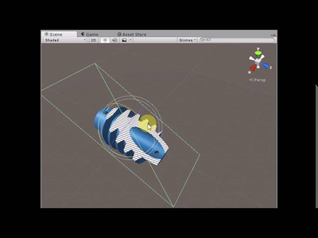
Unity3D Cross Section Shader
Live Demo : https://dandarawy.github.io/Unity3D-Cross-Section-Shader-Demo/
Download from asset store:
https://www.assetstore.unity3d.com/en/#!/content/66300
Github:
https://github.com/Dandarawy/Unity3DCrossSectionShader
I have the cutting behaviour by manipulating the alpha clip threshold.
But I'm a bit unsure how to apply a texture to the regions currently begin cut.
Currently putting it together with shader graph.
Any tips?
I think using stencil seems to be more feasible instead of alpha clip threshold
is that something that can be done with Shader Graph?
Any idea on how much would it cost to hire someone to make a shader like this from scratch? https://assetstore.unity.com/packages/3d/vegetation/trees/stylized-nature-low-poly-environment-186183
I am planing to release a low poly modular enviroment pack on the asset store and want to hire someone to make a custom leaf shader like that that works on SRP and URP so I can include it on my asset.

Elevate your workflow with the Stylized Nature - Low Poly Environment asset from GAMEBYTE. Find this & other Trees options on the Unity Asset Store.
Im kind of lost, maybe someone here can help. I made a custom toon shader and that not the problem, but now i am at the point where i want to make the outlines of the 3d model. I know of the usual method of drawing the backfacing vertices in black as the outline, but this makes it look too 3D for me, wanna do it differently. In my head i generate a texture that has information on where the outline should be, and then use that to draw lines in those places, actual lines on top of the rendered frame.
Figuring out where to place the lines is not my problem, so here is my question: How can i implement a shader/image effects that draws dots of different size whereever a pixel is white ?
like a kind of blur and then smoothstep was my first idea, but obviously unity shader graph doesnt have a blur node, and since the different dots have different sizes, it wouldnt even work for me.
I first wanted to make an image effect, but i realize that what i want to do is not possible with a pixel shader unless I do one pass for every dot
Does anyone have any ideas to share ? Pls im at my limit
alternatively, if someone knows a way to draw outside of the mesh in a normal Shader, that would work too, as my main problem is that a normal shader will only be able to draw lines onside the mesh area
I'm having some issues with getting output from a shader. It looks like it should be working but it just shows up pink. I tried restarting unity to no avail. Implemented a shader that works in another project and it is also broken in this project.
Explain why you need those dots.
I don't get it.
if u use urp then u need to upgrade your materials to urp first
How do you go about doing that? I think I did in another project but don’t remember. Also will that break other textures?
to emulate the way digital art is created, to draw lines on top of every frame by drawing a bunch of dots
Edit->Render pipeline->urp-> upgrade
Thank you!
You are welcome
@torpid lichen but nobody draws with a pixel dither brush 🤔
@torpid lichen if you want to draw outside of the object, the only way is to do a screen space post process effect. You probably want to do something like a custom pass to a custom buffer to generate some metadata you can use for outlining, then go from there with your post process
These dot patterns are called dithering. There are lots of tutorials describing how to implement it in shaders.
if you could mock up an image of what you are after, e.g. in photoshop, that may help people guide you (I'm finding it a bit hard to see what exactly you mean)
I think they want dithering on the line, but also spilling over (eg so that the line is thick but also drawn from dots like a printer dot matrix? not sure)
There's different art styles for dithering/dots/dot-sizes. Maybe they mean that. Sure would be nice to see an example of what they want.
But here's an example of a comic style that uses dots:
https://www.youtube.com/watch?v=7vFdXq-So8g
Then again, toon shaders (regular ones, not dotted) often use outlines. Unity has a tutorial in URP for that one on their tuts pages.
And dots =/= pixels.
So without a more precise description, who knows?

Photoshop CC 2014 tutorial showing how to transform an ordinary photo into a classic, comic book pop art-style, cartoon. This is an update to a tutorial I did on an earlier version of Photoshop.
Yikes! Regular Font:
http://www.dafont.com/yikes.font
Photo provided by http://www.shutterstock.com
High-quality, royalty-free stock images
Photo...
underwater, I want it to be like this, the further way something is the more blue and blurry it is
would I need to write a shader for that?
blurry, yes
just blue, no, fog could do that
Hey, I've been playing around with the shader graph, and I think I managed to get the effect that you're looking for. Since I update it in the editor it's not very smooth and does not reset completely, but it should work perfectly fine in play mode.
anyone have a good idea as to how to replicate an effect like this?
brain mesh..?😁
well the cross hatching on the shadows specifically 😛
could be a duck mesh
depth as in distance from camera, so deeper grooves appear darker?
here's a ref video

We present an interactive illustrative visualization method inspired by traditional pen-and-ink illustration styles. Specifically, we explore how to provide context around DTI fiber tracts in the form of surfaces of the brain, the skull, or other objects such as tumors. These contextual surfaces are derived from either segmentation data or gener...
funny enough, I didn't search unity specifically, but it seems like it was implemented in unity.😅
That shader is in CG
then I am sad

I made this by sampling a cross hatch texture and multipling it by the lights shadow attan in the shadow pass. No idea how to do it in sg
ooo that's pretty nice
would it be possible if I could have that cross hatch texture?
Do we even have access to shadow pass in the shader graph?🤔
Dont know. We use sg for prototyping and vfx materials mostly.
I wont be able to share it today too much work to do, the texture itself is not important, having a shader that handles custom shadows is
Any cross hatch greyscale texture would do
For that brain example at least, it seems like "darker" areas depend on the normal of the surface relative to the camera.
So something near 90 is dark but if the surface is right at you it's completely white
something with depth as well?
ya guess so
That can be done with a dot product of the normal and direction to the camera
wait for depth or the whole "darker for thing relative to angle from camera"
@kind juniper
for "darker for thing relative to angle from camera"
as for the shadows in the crevasses, I'm pretty sure it's some kind of ambient occlusion.
Not sure how to implement it though.

I mean yeah, if you see shadows in computer graphics with no apparent light source creating them, it's most likely ambient occlusion.
in crevasses and corners.
so is this something that can even be done on a shader?
or is it some post processing effect
No clue. The expensive way it's done is that you launch rays from every pixel and see how soon and how many times it bounces off geometry and assign attenuation based on that. It's probably impossible to do in regular shader(unless you pass some data into it defining the AO value of each pixel).
Couldnt I take like