
#archived-shaders
1 messages · Page 222 of 1
the back fin bleeds through when on fade
is there a way to disable this?
while keeping the material type of fade
enable both faces

Why is this happening to a double sided transparent object? @regal stag

Rendering order issue, you can't really fix it with a toggle
Transparent objects render their faces "as they come", without depth testing, resulting to this kind of thing
So... what would you recommend me to do?
First : what render pipeline are you using ?
urp
Hum, sadly I don't think URP has any built-in option to help you fix this :/
;-;
still, thanks for helping me
That was weird. All of the sudden I started getting notifications for this channel
Ideally, you want to draw the back faces first, then the front faces.
You might be able to do this with a render object feature, by isolating these objects in a dedicated layer, and rendering them before transparent + forcing culling to front face
Please also don't tag specific community members if it's a general question 🙂
The draw order for transparency comes up often, is there a good resource we can pin somewhere?
Actually, I meant "both" - but I think I resolved it by copying the shader (in the file system) and opening it and editing the name in the text file, then adding that to a new material and using that material for the one-off font that I wanted that shader on.. My issue was that copying the shader without editing the name in the shader file was leading unity to ... do weird things with more than one shader with the same name
"name" in the shader file, not the name in the meta file / unity editor
Keep in mind that the vertex order is editable in a 3D-modeling package, so you actually have quite some control over this, when within the same mesh. If you can afford the overdraw you can have a couple of inside pieces giving the impression of interior depth as well. I probably would have solved this in another way if it's meant to fade out though. Like with a rendertexture or dithering.
If you keep the backface culling, and instead add those faces in the mesh, you can easily sort simpler shapes.
does anyone have an example of a simple depth map shader that actually works?
You'll have to be more specific, depth works differently in each of the render pipelines.
how can i fix my shader failed to compile?
it was working few mins ago now it says failed to compile
you may have accidentally added something
are you using any source control, e.g. git? then you can easily compare between versions to see what changed
well i added one unity store assets after that it said that
i deleted that and now it compiles again
but the art assets for that package are good looking kind of wanted to use that
Is GetTexture slow?
I want to create a new material with new shader in specific situation in the game
I mean replace the old material with the new one. Both use same main texture.
So first, I get it with material.GetTexture and then set it to the new material with new shader, any better solution?
It should just be returning the texture reference. Why the concern? If you cannot keep track of it "manually" in code, then get the ref off the material. Meh. It's all on the C# side anyway, the shaders/GPU won't care.
Well, as has been explained above (I think), transparents don't set the depth texture, and additionally, they draw over top of things that are behind them (further from the camera/deeper).
So that's what you're getting. Are the yellow fins opaque like a 2nd material? Or is it "just" stacking transparents on top of each other?
Like Remy and Frell mentioned, there are "tricks" depending on what you want to happen.
The dither is a really easy solution, though, if it is acceptable. Since it is an opaque process and won't suffer from the same problems as transparent stuff (at least not in screen space).
See here: https://dev.rbcafe.com/unity/unity-5.3.3/en/Manual/SL-CullAndDepth.html
Where the transparent shader does depth writes, and only depth writes, first.
The solution in that link is to render "nothing" to the color buffer but update the depth buffer using "ColorMask 0" and "ZWrite on" in the shader. This sets depth clipping for those "behind" pixels.
Then you make another pass and draw it "for real" and only the front sides get drawn, which should omit your yellow fin and any deeper pixels than the front sufrace, as they will get clipped as being occluded.
That link is assuming built-in pipeline. URP/HDRP will probably require a hand-written shader, but I'm unsure of that. Maybe you can set the colormask and zwrite in Shader Graph....IDK. And you need either multiple passes or some of that new fangled render features stuff piled on top with extra frosting.
Unity is the ultimate game development platform. Use Unity to build high-quality 3D and 2D games, deploy them across mobile, desktop, VR/AR, consoles or the Web, and connect with loyal and enthusiastic players and customers.
Could someone help me with how I could convert this shader graph into shader lab code

anyone have any ideas as to where i can find a quick water shader for SRP?
currently all the ones im seeing only work with urp or hdrp
default pipeline, v 2020.3.20
any clue on why this might be happening?

i wanted the texture to scroll
but instead it is distoring
even tiling is doing it

It seems you have wrong texture wrapping mode
It should be set to repeat (from import settings of texture)
If it works for urp it should probably work for SRP too...🤔 Unless by SRP you mean something other than Scriptable Render Pipeline..?
people use SRP when they mean BIRP for some reason
I've got some simple BIRP water here : https://www.patreon.com/posts/24192529
how do I copy default asset to edit (I want to edit the sun texture)

Is there a way to take some perlin noise, define a gradient, and then color a model based on mapping that gradient to the perlin noise?
so the perlin is sorta like a height map?
Any theories on how this nebula effect was produced? I am not really seeing ray marching artifacts and I am wondering if its a true volumetric effect or just some clever solution?

EVERSPACE™ 2 is a fast-paced single-player spaceship shooter with deep exploration in space and on planets, tons of loot, RPG elements, mining, and crafting. Experience a thoughtful story, set in a vivid, handcrafted open world full of secrets, puzzles, and perils.
This live stream is part of our weekly communication with our community to showc...
and height defines color
So I have a very basic shader here. Literally just makes some noise, colors it and then applies the texture. When I apply it to the default models (such as the sphere) all is working. However when I apply it to my own models, for some reason they're always black.


In fact, it seems that I can't make these models anything but 1 solid color.
So I assume something is off with them.
Any tips?
Going to assume something something fucked UV mapping
Make your color map a texture, then use the value from the perlin mode as one of the uv coordinates to sample the color map
the color you're multiplying with isn't the basecolor
huh?
oh wait I misread
np
you can quickly generate lightmap uvs for your model in import settings, and then use UV1 to see if it shows up then
if it does, its your original uvs
kk 1 sec then
ya definitely the original UVs then
not going to lie, a bit unfamiliar with the concept
can I get a tl;dr on whats with the solid color?
I assume it's only sampling from the single pixel on the bottom left
instead of wrapping the whole texture around itself?
well it looks like youve got no uv map at all, so theres no data to sample on
Ye, suboptimal.
Could anyone help me with how this node translates into shader lab?

specifically just world space view dir
It's the vertex position subtracted from the camera position, both in world space (_WorldSpaceCameraPos - positionWS), assuming a perspective projection (orthographic uses the forward axis of the view matrix instead). Can see the function in the URP ShaderLibrary source : https://github.com/Unity-Technologies/Graphics/blob/d0828e062dbffe99c6c07062e841ed4eff68fb37/com.unity.render-pipelines.universal/ShaderLibrary/ShaderVariablesFunctions.hlsl#L95
Thank you
Hello, I'm a front end developer and i want to do this shader, does anyone have any idea? https://monopo.london/

We are a design-driven creative agency working accross branding, digital design and communications. Based in London, born in Tokyo.
thanks
Hi. How to measure the performance of the shaders? And I need something more accurate than just measure the fps 😉
@languid zodiac if you need something built-in, could start with unity profiler's gpu module
oh wait, you mean like regular shaders... yeah that's harder
yup, thats a problem 😛
Does anyone know if shadows rendering over a shader is a generic issue, and how to fix it?


Does alpha clipping shaders breaks batching ? For example, having multiple trees overlapping with alpha cutout, seems to increases my batches count a lot even if they all have the same material and are statics
Havent seen that before but one thing id try is to change the render queue of shader
why is my depth texture only applying 1 color to everything at once

also how to I remove an object from the depth calculation
oh... its only sampling the depth of the pixel in the bottom left of my screen
How do I sample render texture in a compute shader
You can override the preview type on the node via the Node Settings tab of the Graph Inspector, if you're in Unity 2021.1 / SG v11+ that is (at least I think that's when the option was added)
Oh it might be a 2021.2 beta thing actually
Will the Shader Graph 12+ version work properly on Unity 2020.x ?
Just need a ZDepth property
Anyone tested?
This worked, thank you!
Why does my shader behave differently on mobile when using LoD? It works fine with LoD on editor
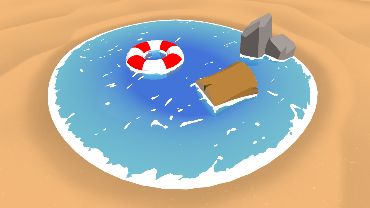
void surf (Input IN, inout SurfaceOutput o) {
    float2 uv = IN.worldPos.xz * 0.025;
    float3 n = IN.normals;
    float4 sea  = tex2D(_SeaTex,  uv + float2(_SinTime[1], _CosTime[1]));
    float4 sand = tex2D(_SandTex, uv);
    float noise = sin((IN.worldPos.x + IN.worldPos.z) * 0.0888) * 0.5;
    float sandStart = IN.worldPos.y + noise - 2.5;
    float sandEnd = sandStart + 0.5f;
    float4 g = lerp(sea, sand, clamp(sandStart + sandEnd,0,1));

    sea = tex2D(_MainTex, uv);
    sandStart = IN.worldPos.y + noise - _SandLevel - 1;
    sandEnd = sandStart - 2.5f;
    g = lerp(g, sea, clamp(sandStart + sandEnd,0, 1));

    float4 r = tex2D(_RockTex, uv);
    o.Albedo = lerp(r.rgb, g.rgb, saturate(pow(n.b * (1 + _GrassAngle), 16)));
    o.Alpha = 1;
}```
[Shortened to save space]Here's on mobile, notice that the texture always become rock texture on LoD mesh

Why do the splatmaps Unity terrain generates have this effect?

If I paint close to the edge, it creates a line of pixels on the very edge.
Huh, it stopped appearing once I applied the same custom renderer to all terrains.
Oh nice. Didnt expect it to work but said anyways
is there a way to scale a number range at a certain position between 0 and 1 ? right now im sampling two gradients ( the first one 0.5 value is shifted to 80% and the second one is to 20% )

but i suspect its isn't very performant compared to a math function
anyone know how to make a transparent mat in HDRP that you can see particles and other transparent objects threw? having glass act as a cloaking field for particles is not ideal and I figured this would not be a problem in HDRP but I guess it is
I guess you want a transparent object with refraction ?
yes
I guess you should be able to use remap nodes instead of the samplegradients.
for basic windows I can live without it if I must but part of the reason we switched back to HDRP is I was told you could get refraction or similar distortion effects on trasparent objects. I have seen videos of it. just cant find anything explaining how its done
Ok, well then, no.
But, you can think it the other way around : if your particles and transparent objects shaders are set to the "before refraction" mode, they will be visible in the object with refraction
that would require me to use the actual refraction effect in HDRP, not scene or HD scene color?
iirc, it will act the same, the HD scene color samples the same buffer as refraction materials
ok, will give it a try. thanks
trying to create a blackhole shader effect similar to this. https://www.youtube.com/watch?v=8e6vftYaAIc

Liking this video is the EASIEST way you can support Shader Graph Mastery, it helps a lot with the Youtube Algorithm.
This Black Hole is made with Unity VFX Graph for the galaxy ring around it and Shader Graph for the warping effect.
I've been using Unity's High Definition Render Pipeline these past few months & have many more graphic projects ...
hey everyone I just finished a tutorial after downloading the universal shader pipeline and made a triplaner shader, and Im at the end but my final output node dosent have anything to connect to and I get the error no output selected, I assume I should have a starting node thats a texture output so Im geussing I messed up and the graph is made in the wrong location, am i missing something super obvious here?
did I mess up by doing everything in trigraph instead of the material?

Connect the last add node to "base color" ?
so the node that says fragment is my end point? the tutorial was using the other pipeline.
the node that says fragment is my end point
I don't get it
I connected my final out to that but nothing happened earlier, I assumed that wasnt the right plug and Ive been scratching my head on where the right connection was, but Ive found the issue my outs are vector4 so i need to remove oppacity
thank you for the help
Really ?
A vector4 is automatically cast to a vector3 and the .a value is thrown away
I cant figure out how to set a vfx graph particle to be "before refraction" no option that I can see for the particle, I tried setting it to a shader graph mat that was set that way and it didnt work... this is what I am stuck with

iirc, it's in the inspector, when the output block of the graph is selected
ah, thanks... now I am getting somewhere
progress, still fighting me in some odd ways.

honestly I have no idea what im missing still when I put it in base color its just appearing purple. I tried putting it as base textur too not sure whats up with it still
since my first picture was really undreadably small, Im sure its something stupid Im missing.

Hihi, I'm wondering if it's possible to make a shader in shadergraph that would take an objects geometry and make a cutout to display a flat texture like so:

I don't quite know what kind of effect is called so I'm not sure where to start researching- if someone could point me in the right direction or an idea to achieve it I'd greatly appreciate it!
Purple means shader is incompatible. If the problem was with the output, you'd get white or black - the default color.
Are you actually using universal render pipeline properly?
why is this only setting the screenPosition variable to the lower left corner?

Im not quite sure what you mean but ig thats called screen space texture
The way you do that is sampling the texture in screen space coordinates, rather than the mesh's UV
how to lern shader language in unity?
Read the manual, follow tutorials...
can you advise tutorials?
maybe this to get started:
https://www.youtube.com/watch?v=3penhrrKCYg&ab_channel=Unity
thanks
You screwed with the o.vertex by adding in the results of the wave function. Which may or may not be OK to do. (I realize you're doing vertex displacement, but IDK what the function resulted in).
Just as a test, try commenting out the wave() function call line.
ComputeScreenPos takes the clip-space result, just as you're doing it so it should work if all the math is OK.
Also, I have no idea if your frag() is messing up the result, but that's a different question, I suppose. You're assuming that it is wrong output in the vert() per your question.
no luck. heres my frag if that helps

OK, you have multiple inputs to the frag()
But your v2g o should be set from the vert().
You have too many things going on at once to test.
How do you know that o.screenPosition (after commenting out the wave() function) is wrong?
What do you mean by "no luck"?
nothing changed, the waves just dissapeared
yes. for context its only sampling the bottom left corner of the depth texture when changing to water color for some reason

IDK...I haven't read that article you're following.
IDK about that math at the end of the frag() either.
Black is black.
So...
Let's output some info for testing.
Change the frag(). Output the values of the screenPos result
But you'll have to scale it
So...
black (0,0)

return fixed4(o.screenPosition.x/width, o.screenPosition.y/height, 0, 1);
or something...where width and height are your screen width and height
Comment out the other stuff in frag()

OK, fair enough. I was still working toward that when you added this info. 😉
And you commented out the += wave() line in the vert()?
IDK, it looks like it should work.
One thing though...it depends on the math and the technique...but it's common to add vert offsets in object space too/instead.
You could try just adding a 1.0 to the Y value manually, hard coded, and see if it moves up.
But that's a bit beside the point. I'm just trying to isolate variables.
Anyway, those calls SHOULD work, from what I can see. Maybe someone else will spot the problem.
oh I figured it out, tyty
Wait! Try
return float4(o.screenPosition.xy, 0, 1);
wait... why the heck is screenPosition a vec4...
I was just reading that. And it might be returning UV coordinates for a texture sample! So they'd be from 0 to 1. Still, I'd have thought you'd have more than just black.
But you're also returning 0 alpha, and IDK what queue you're in.
Or that alpha is a larger number due to perspective divide.
So you're getting really small results. IDK, so isolate the xy part.
Might still be black, which is throwing me.

Frack. The comment here above the function is confusing:
https://docs.unity3d.com/Manual/SL-BuiltinFunctions.html
The following functions are helpers to compute coordinates used for sampling screen-space textures. They return float4 where the final coordinate to sample texture with can be computed via perspective division (for example xy/w).
So it sounds like CSP is returning the actual integer values, and the w is a perspective divide number. Oy. But we don't want to sample a texture with this anyway that I know of, so we don't need to normalize it.

why is it a float 4
OK, but the important thing to note is that it is NOT ZERO.
Did you try xy/w?
I think (they should document this better on that page)...
The x and y are the x and y screen locations, the z is the depth and the w is the magic "perspective divide" depth number that makes a 3D frustum work. The further away it is, the more it gets moved toward (0,0) in clip space.
But I'm unsure from that document what the xy values really are.
Docs say Computes texture coordinate for doing a screenspace-mapped texture sample. Input is clip space position.
So yeah, what dlich just said. But still, I think you're after the actual pixel int value. Like pixel 396 of 1024.
but IDK if that's what you want
tex coords are 0 to 1
I think the screen space position needs to be calculated in the fragment shader as opposed to be passed in from vertex
It probably gets interpolated in a weird way and you get weird results too
That makes total sense, dlich. I didn't even think of it. Doh!
Because rasterization...
The vertex stage has no idea about pixels yet.
well thats something...

What's the current code?
That makes more sense. Reds and greens
share it with backticks
Sorry @tidal cypress, I missed that. I just followed the yellow brick road.... Good catch dlich.
great, but the coords repeat every tile

also theres a weird white line down the middle
Share the updated code properly
That's not what I meant(look at #854851968446365696 on how to share code), but ok...
oh that
           fixed4 frag (v2g o, g2f i) : SV_Target //from https://roystan.net/articles/toon-water.html
            {
                /*float existingDepth01 = tex2Dproj(_CameraDepthTexture, UNITY_PROJ_COORD(o.screenPosition)).r;
                float existingDepthLinear = LinearEyeDepth(existingDepth01);
                float depthDifference = existingDepthLinear - o.screenPosition.w;
                float waterDepthDifference01 = saturate(depthDifference / _DepthMaxDistance);
                float4 waterColor = lerp(_DepthGradientShallow, _DepthGradientDeep, waterDepthDifference01);*/

                float4 screenPosition = ComputeScreenPos(o.vertex);

                half depth = SAMPLE_DEPTH_TEXTURE_PROJ(_CameraDepthTexture, UNITY_PROJ_COORD(screenPosition));
                depth = LinearEyeDepth(depth);

                return float4(depth/10 + (i.col.rgb/4 - 0.1), 1);
                //return float4(screenPosition.xy/screenPosition.w,0,1);
            }
You didn't apply the other fix from earlier.
The following functions are helpers to compute coordinates used for sampling screen-space textures. They return float4 where the final coordinate to sample texture with can be computed via perspective division (for example xy/w).
Why do you need UNITY_PROJ_COORD though? Is it from a tutorial?
yes
Hmmm... then I'm our of clues. Is the math correct(the same as in the tutorial)?
Im pretty sure it is
Can you link the tutorial?
Learn to write a toon style water shader for Unity engine, complete with waves and shoreline foam.
Interesting. They seem to be computing screen position in vertex shader and it works for them...
theres a lot that works for them
because theirs requires me to build it all the way up and it doesn't have all the features I want
build all the way up? Wdym?
paste in his code
its annoying
because I have no way of knowing if he set up one step wrong
Here's how they get the depth value:
// Retrieve the current depth value of the surface behind the
// pixel we are currently rendering.
float existingDepth01 = tex2Dproj(_CameraDepthTexture, UNITY_PROJ_COORD(i.screenPosition)).r;
// Convert the depth from non-linear 0...1 range to linear
// depth, in Unity units.
float existingDepthLinear = LinearEyeDepth(existingDepth01);

// Difference, in Unity units, between the water's surface and the object behind it.
float depthDifference = existingDepthLinear - i.screenPosition.w;
Quite different from what you have.
The tutorial? You can get the project from the github, make sure that it works, then adjust the shader to your needs. Way simpler than trying to write it from scratch.(Although I guess you'd learn more from that)
yes
its happened to me with almost every tutorial like this. the guy who makes it changes something down the line and forgets to update the steps above
These lines are the same as in the tutorial though.
If the tutorial has source code, you can be 99.9999% sure that it works. Heck, if you don't trust it, just test it.
you underestimate how lazy I am
Well, that's a different problem. And we don't like helping lazy people here.😅
fair enough
I'll deal with this in the morning
anyways the depth texture is working, but all the planes are sampling from the same location
lol
We've spent more time screwing with this, all three of us, than it would take to start with a working tut.
But we've confirmed something....
ComputeScreenPos WAS NOT 0.
And we found that it CAN work in the vert() per the tut. (I guess Unity always knows what it needs for that calc, vert or frag)
And the rest is you (@tidal cypress) debugging your math/calcs.
for some reason it's like the o.vertex variable is relative to the plane's location, not the world's
Can you share the vertex shader again?
o.vertex is going to be clip space in the vert() shader. Vert() shaders output clip space.
I have no clue what clip space means
            v2g vert (appdata_base v)
            {
                v2g o;
                o.worldPos = mul(unity_ObjectToWorld, v.vertex);
                o.vertex = UnityObjectToClipPos(v.vertex);
                //o.vertex.y += wave(v.texcoord);
                o.uv = v.texcoord;

                o.screenPosition = ComputeScreenPos(o.vertex);

                return o;
            }
-1 to 1 in x and y, (0,0) is the screen center.
Z and W get more complex to explain.
Z is a depth of some type.
W is the "perspective divide" where you divide XY by W and get it "squished" from a pyramid type frustum into 2D "flat" screen space-ish type of thing (NDC may not be the exact term in this case either).
It gets a tad complicated terminology wise.
It seems similar to what they have in vertex shader, so I'd assume that the problem is in your fragment shader.
Yeah, as long as the function call works in vert() ...and I should I guess...then it should get interpolated OK against the flat 2D results.
So yeah, frag.
Whatever the hell is in XY, it should be lerped properly for the polygon being shaded.
And Z is a depth. (Which was also decoded in the vert, so that result should interpolate).
W is the perspective divide value.
What's your real question? Because...
https://letmegooglethat.com/?q=unity+procedural+skybox+shader+graph

LetMeGoogleThat.com
For all those people that find it more convenient to bother you with their question than to google it for themselves.
Rotating a cube via shader is actually pretty difficult. 😄
What happens when terrain renderer gets a regular material not written for terrain?
Does it keep invoking the ForwardLit pass for each 4 layers?
You mean Unity's version of a procedural sky shader? (That specific one).
OK, fair enough.
IDK of a specific link though.
No apology necessary, but the clarification was helpful. 🙂
They don't have a fallback like that. The layers would have to be drawn transparently to blend them on top of each other, and still read the splatmap to know where each layer is supposed to be drawn.
If the shader doesn't read the splatmap, it can't know where the layers are supposed to be.
I know how splatmapping works.
I'm feeling too lazy to implement quad tree rendering for my terrain.
I have 1 shader graph into which I pass the splats in a texture array.
And I wonder if it will fuck my shit up and render the material 4 times for 32 layers in total if I use the material on the renderer itself.
You're wondering if Unity is detecting if a shader is a proper terrain shader, and if it's not, it will draw the terrain 4 times?
No.
Darn it.
How it does rendering is it draws a patch in a new draw call for each 4 layers for each 4 layers after the first ones.
Cause a splat is 4 channels.
You mean when you have more than 4 layers?
To be fair, you didn't mention 32 layers at first, so I assumed by 4 layers you meant the 4 channels of a single splatmap
I don't know the answer, but my guess would be yes, it would treat it like a regular terrain shader.
It's just there is literally no way for me to test if the shader is being invoked by the base or additive pass.
I see some people on Unity forums just don't give a fuck and use a graph but like I wanna find out if it will turn my single pass mega terrain shader into quadruple drawcalls for no reason.
Stupid how the terrain lives fully on the C++ side.
With the terrain turned off, I have 5 draw calls.
With a simple PBR graph - 17 calls.
With a Terrain Lit shader - 27 calls.
🤔
And the number of verts changes depending on the material.
Very weird.
Oddly enough, the number of layers doesn't impact the drawcall count.
Wtf.
IDK either. But those are pretty small #'s, Beat. Not that I object to you asking at all, but you may not notice much difference.
Incidentally, draw calls aren't always the prime factor.
I mean, it's more about CONTEXT switches, that show up between draw calls. Not every set of draw calls is a context switch. Sometimes, like for various batching, it's the same context but done in "groups" due to buffer size limits or whatever. IIUC.
https://gpuopen.com/learn/understanding-gpu-context-rolls/
And for fun, check these stats:
https://pcper.com/2015/08/what-exactly-is-a-draw-call-and-what-can-it-do/
They're talking about some games in 2015 with 50,000 draw calls. That's pushing it....back then.
And note that various APIs can handle draw calls better, like DX12, depending on your needs.
Like many things, running some test cases in various ways if you can...and timing them with benchmarks....helps you decide. It's hard to test all device types though.
Sometimes you're more limited by the # of vector registers you have available that stops some thread groups running, limiting your throughput.
The only way I've found to analyze all this crap is to use the GPU manufacture's GPU analysis/debugging tools.
2 cents.

GPUOpen
Learn what a context roll on our GPUs is, how they apply to the pipeline and how they're managed, and what you can do to analyse them and find out if they're a limiting factor in the performance of your game or application.

What Exactly Is a Draw Call (and What Can It Do)? Mantle, Vulkan, and DirectX 12 all claim to reduce overhead and provide a staggering increase in “draw
P.S. I assume a material change will result in a context change. At least that's a safe assumption.
@meager pelican well, it's just I wouldn't want it to call my single pass shader multiple times.
I have my own constant grid terrain renderer but that breaks as soon as you make a small hill cause not enough detail for the slopes.
It'll make a difference for me if it's a hacky thing that I shouldn't use in prod or something I will do in next projects.
Btw I tried to make reconstructing normals from height work using code from Battlefield Bad Company 2 but it produces shaky results...

I checked the theory and everything seems correct

But it just doesn't produce normals as smooth.
Here it's obvious they sample it in frag cause Sample is only available in frag.
can anyone help me get started w/ creating a custom Shader Graph node that emits Unscaled Time?
worst case I will use Shader.SetGlobalFloat but I'd prefer doing it w/ a custom node if possible
ok so the tutorial shader works, but not on planes?


anyways this really isn't what I need because it changes with perspective, which doesn't make sense for sea foam
so I need a way to get every frags distance from the nearest intersection or geometry beneath it
so i was messing with procedural generation with shader graph and i cant figure out how to calculate the normals from that. if anyone could point me in the right direction id rlly appreciate it
depends. what kind of shading do you want
idrk what that means sorry but just the normal calculations that mesh.RecalculateNormals would do
wait so are you doing your displacements in the shader?
yeah
because they should really be in a normal cs script
yeah ik but i want as many frames as possible
you just edit the mesh once, then never need to generate that ever again
true
it's loading chunks, you only need to generate them once
Is it possible to get mesh data after applying bone transformations on him?
Hmmm....maybe try playing with those float2 offsets...
Another thing I've done is construct a normal from THREE samples...there's a calc to get a normal from 3 verts, don't remember off the top of my head, but it might save a sample.
I assume those sand-waves are your complaint...(they look kinda cool if that's desert). 😄
Another normals question!
I guess I'll have to dig up that calc for fun. Second...
after looking back into it I did not know to change project settings, thank you for the guidance
Surface normal from 3 points is calculated by making 2 vectors on the triangle from the 3 points, and taking a cross product, if the points are ordered counter-clockwise it is:
Given float3 a, b, c
float3 normal = normalize(cross(b - a, c - a));
@low kettle@grand jolt
thank you!
Per: https://stackoverflow.com/questions/1966587/given-3-points-how-do-i-calculate-the-normal-vector
Also see: https://docs.unity3d.com/Packages/com.unity.shadergraph@7.1/manual/Cross-Product-Node.html

Stack Overflow
Given three 3D points (A,B, & C) how do I calculate the normal vector? The three points define a plane and I want the vector perpendicular to this plane.
Can I get sample C# code that demonst...
Uh, holy frack.
Doing a depth-based (or ray from camera/eye) can be done. But otherwise, you're basically doing some kind of ray tracing, or screen-space to world-space, across the screen unless your scene is procedural-math based (like SDF's). Or some other really expensive maybe not real time kind of thing.
I mean...one mesh doesn't know about any others in a shader unless you pass them all. All it has is the depth buffer, g-buffer, etc.
uhh can I just send a ray down from the frag for a few units then see if I hit anything?
OK, that's ray tracing/marching.
But you have to have your scene in GPU memory to pull it off.
OR
You'd have to do what I mentioned....use the depth buffer to calc the world-space position of any other background pixels (which would exclude much/most of the current mesh) and then do a nearness check relative to some saved value. Basically casting around on the screen near the object.
it seems like my ground planes aren't being included in the depth calculation
Wait.
Are you just needing the distance to the ground plane?
You can pass in the ground plane's Y coord.
Calc distance from that.
Is this the water thing?
That's the depth buffer calc from the background data, along a ray from the camera, maybe refracted a bit.
That's what those formulas did in the tut.
But that's WAY different than "any and all nearest geometry"....it's just one ray.
it should be good enough
Yeah, you can do that. The tut was doing that.
which tut?
That one, see first image with the rays and the water.
not really, that isn't depth straight down
so how do I send in the vertices of an abject into the shader?
OK, then it's not a plane you want, but the scene depth Y value distance between the water and the bottom (in other words, bottom is irregular, not a plane).
OK, tracking now.
So, you also don't want eye depth, you want world-y depth. That's harder, and not accurate to the eye, but it can be done.
So you're talking about casting rays "down" along the Y....
But another way it can be done is to have a 2nd camera (this is not uncommon) to calc Y depth from above. So you position a camera pointing straight down the Y axis, and take an "image" of the scene using that, and store the depth into a single-channel render texture.
Then, "all" you need to know is the x, z value of the world-space spot the ray hit the water, and that's your x, y value to lookup into the height map texture that you generated from that other camera.
Sort of, in theory. I mean there's info on the net for it.
Computing the right position to look up is likely more complicated than that.
so what im thinking is that since both the water and the terrain are the same type of plane with all the same vertices, if I can get the vertice of the terrain that corelates with the water I can get the distance between them
What is this terrain?
Is it a unity terrain? Or a mesh? Or what?
a default plane
How are you making hills and valleys?
cs script
Height map? You already have a height map?
Use that.
no
it's the perlin cs function
and theres also a bunch of stuff done to the heightmap
unless you mean to generate a texture from that, but I don't know how I would pass that to the water
Well, once you get that all generated...yes....generated a texture as you go.
It's a texture. You know how to pass textures to shaders, I'm sure.
There's a .setTexture() call to set it on the material.
https://docs.unity3d.com/ScriptReference/Material.SetTexture.html
You might want to use sharedMaterial.setTexture but meh.
The texture is a shader property. Google it.
yeah ok that should work
Then you don't need to screw around with 2nd camera and ray tracing...you already had the data in C#. 🙂
how to I fix the problem with unity's awful texture scaling
Too vague to answer....
for example, the reason I have this awful blending is because the texture is blurred by scaling, then I sample a color from the triangle center

@meager pelican but a 4 tap cross should give better results than 3 taps 🥲
Thanks for the help. I got it working

Hello! I grabbed the shaders from this video: https://www.youtube.com/watch?v=GGTTHOpUQDE, however I have an error in a few shaders:

Does anybody know how I can fix this?
define shadowcoord correctly
float4 shadowCoord = TransformWorldToShadowCoord(WorldPos); this is how it's defined - can you help me in finding what's wrong about it? I'm sorry, I'm a beginner at this
is it being called in the same frag / geo / vert as it's defined?
if it is, when it's called it should just be shadowCoord, not x.shadowCoord
I guess so - I'm actually using the original file from the unity repo, with no changes made by me

thats weird, I don't see it being used as subtext anywhere...
Which shaders do you guys think would be better to emulate this art style on a 3d enviroment?
I thought about using default shaders but could also use toon shaders. The lighting details are more visible with default shaders tho.

turn up the bloom
can someone please give me an idea of how to fix this? It's a .vrm model I'm trying to export. Whenever I activate an expression, these red spots appear all over the face as I rotate the screen. All I did since this started was add some blendshapes, but I suppose a lot could happen between blender and exporting from Unity.

When the face is in the original, neutral sate, it is normal.
looks like overlapping geometry
that's what i think it looks like too, but I don't see anything that would be overlapping. It's just a single face mesh there
you can delete the overlapping texture with image editor.. I'm using vrm as well for my current game
I will take a look at that, I'm still kinda new so I might be missing something
thanks for your input!
for further info about this issue you can see it here https://vroid.pixiv.help/hc/en-us/articles/360012304254-Skin-is-visible-over-clothes
Ohh I'm not using vroid anymore; I have working versions of this model already, but basically what I did was opened up the working fbx in blender, added a bunch of blendshapes to the head and then replaced the head on the model with the updated one. Did the whole process of transferring from FBX -> Prefab -> VRM, and now whenever I activate any expressions at all on this updated model, the head does this
as long as you're using the same UVs it will still be the same
or just deflate the neck part a little bit in blender
either way, this is not shader related question
you can use simple-deform modifier for this, or else just scale the edges manually
Hmm okay I will try this, thank you! I first thought it might have been the VRM mtoon shaders breaking it

update: I actually fixed this issue by making both of these boxes white under the shader
not sure why this suddenly needed to be done since it was working in past iterations, but  I suspect this is a temporary fix and something is causing the shading to mess up
does anyone have a good tutorial i can watch on shaders? I'm a bit confused. I got a free asset on unity for Lava flowing shader. I've got it to work using the prefabs they've given. However I would like to try to get it to work by using the shaders and mixing them together to get desired effect?
hey, does anyone know if its possible to modify light/shadow direction in URP Shader Graph? im trying to change the shadow direction for specific objects, so that its different from the default directional light value
My guess is that if you're using a lit shader graph, it's going to do default lighting. (It generates the lighting stuff for you).
You're asking, I think, for custom lighting.
That puts you into the realm of either using unlit shaders and putting in your own lighting system, or hand writing shaders for URP.
You might be able to pull some tricks....like use a 2nd camera, and between camera renders, screw with the lighting info on the C# side to change directions, but for things like point lights, that probably won't work.
Well, since it is a toon shader, it could be that somehow the normals or vert data is screwed up in the model after you "activate an expression" and the shadow calcs are all f-ed up as a result.
But then, that's likely a problem with some other component....modeling, import, skinning, etc.
Nice.
You might be able to pull it off with the "default shaders"...a lot of it is asset creation and settings.
But, since you didn't indicate what pipeline you want to work in, I'm not sure how to answer.
If you want to have control over the whole art style, you end up writing all custom shaders AND custom lighting. In the built-in pipeline there's surface shaders and custom lighting functions that can be auto-inserted into the results (you still have to write them, but there's syntactic hooks for it).
For URP or HDRP, I'm unsure, but can almost guarantee you'll have to hand write shaders.
And since you asked this question this way, I'm going to assume that you're not familiar with hand-writing your entire shader system. So unless you find an asset to emulate all this, IDK what to tell you.
This is why many AAA studios, if they use a third party engine at all, end up writing a ton of custom shaders AND have a 10x ton of artists in the mix. There's usually more artists/modelers than programmers, IIUC, and most all the shaders are custom.
So they have complete control over everything, and don't do any "extra stuff".
But that's not to say that if you're willing to compromise that you can't get a great look with standard shaders. You can.
If you want to use standard shaders, you might try the art-asset-workflow and the lighting sections of this discord.
I'd track it down by digging into GetMainLight() and SampleShadowmap() and figuring out if you're passing the right stuff. Something may have changed on those function calls, or there's a problem with those, not the calling-code.
Thanks, I'll try to do that.
Ey people i'm working on a real time GI Shader, but i have a small problem, i'm checking for a pixel on texture and not 50 pixels for example any idea how to grab 50 pixels and do a and set it has 1 pixel
any idea how to do this
i'm using Amplif
hey guys. I'm writing a very simple blur effect. .trying to do it all in one PASS. what do u think? I managed to make a blur over x axis. now how could I make it blur circular ?

Im doing a simple box blur
calculating y just like x, in the same PASS , will result in this... which is bad...

is there a way to make bullet holes using shaders?
if so would it be the easiest way to make dynamic bullet holes?
What you want is decal
yeah found it
thanks
oh and also
do you have an indetail shader tutorial?
it would help a lot
That's the 2nd or 3rd time so far today someone wants a magic link to a shader tutorial that explains everything....and really...they don't exist. (No offense meant).
BUT
There are some links in the pinned messages above in the toolbar:
Such as https://thebookofshaders.com/
and https://developer.download.nvidia.com/CgTutorial/cg_tutorial_chapter01.html
(both are getting dated, the cg one is fairly old but worth reading)
And there's several low cost online classes about GPUs and programming them, I've personally taken one from Udemy, and there are others. And of course many books available...e-book or paper.
And you can cobble it all together from various tutorials and videos on the net. Just google "what is a GPU" or "Introduction to GPU programming."
You won't find any single-simple answer here or "best one" because, frankly, we all have our own opinions and different ways of working/growing.

The Book of Shaders
Gentle step-by-step guide through the abstract and complex universe of Fragment Shaders.
thank you!
Graphics researchers waiting in the water fountain line at SIGGRAPH Yellowstone.
Computer graphics as a field is broad, deep, complex, and intimidating. More than half a century of rapid progress driven by academic research and industry practices underly it. Parts delve pretty far into physics, math, signal processing, systems programming (and...
this might be painfully obvious, but how do I get rid of these "shader unsupported" messages in my server build? using URP
guassian

im a bit new to shaders and whenever i plug in my sprite texture it stretches like this

any help is appreciated :)
that's normal for sprites. It should be okay to plug it into the base color. Then, do not forget to plug the alpha to the alpha output of the fragment
What would I do if I wanted to make a ps1 style resolution for my game?
For aesthetic purposes, of course.
Did my resolution bit help at all?
Hey guys, I'm working in Shader lab and need to only use a small portion of my mask map(The blue portion in this case). The tutorial video suggest I do this
// Albedo comes from a texture tinted by color
            fixed4 c = tex2D (_MainTex, IN.uv_MainTex);
            fixed4 mask = tex2D(_MaskTex, IN.uv_MaskTex).r
            c.rgb = c.rgb * (1 - mask) + _Skirt * mask;
The second line, getting the mask value would be fine if it wasn't red. I need to get a mask value that has a mix of rgb. Any assistance would be appreciated!
how exactly you want to get a mix of rgb? The grayscale value of the mask texture? @slow rain
https://gyazo.com/cb04b49e9e346301e5eb2b02c910ffbc
I just want use the violet (pink) portion of the map when calculation my shader.

Normally, a mask should be single value in one of the channels (r, g, b or a), so you sample the texture, then use any channel you like. For this texture, you could draw the violet part in red channel, and the blue part in blue channel and then easily use it as mask
But if you really need to use this one, what I can suggest is to filter the colors that match the pink.
It is r = 1, g = 0, b = 0.91.
first sample the mask texture
fixed4 mask = tex2D(_MaskTex, IN.uv_MaskTex);
Then, you can use step() to get pixels that are r = 1, and combine it with b > 0.91
float m = saturate(step(1, mask.r) + step(0.9, mask.b));
use saturate to clamp the values between 0-1
now you can multiply the color with 'm' to mask out. But strongly advise to try using separate channels, this is not a good way to handle this I believe.
It ended up being the normals being messed up when a toon shader was applied, as I had the blendshape normals set to calculate in Unity. Changing that setting fixed it. Thanks for our input!
So i created a URP unlit sprite shader graph and this happened

anyone got any idea why
Looking through this now. I'll ask if I need anymore assitance Epetha. Thank you!
did you pass the texture alpha to the alpha output of the fragment?

try this

@hollow talon I have another question as well. They actually did fixed4 mask = tex2D(_MaskTex, IN.uv_MaskTex) instead of MainTex for the second parameter, do you have any clue why?
that uses a dedicated UV for the mask. You can apply tiling and offset to the mask this way, without altering MainTex's. Should not be necessary to have it I guess
That's interesting. noted! Thank you!
@hollow talon on the second step, should it be b or mask.b?
Yeah, should be mask.b, oops 😅
No worries, I do the same. lol
hey @hollow talon , how did you decide on those values for the pink?
I colorpicked it on GIMP
Could I possible hop in a call with you and pick your brain?
https://gyazo.com/a081545fc2f74e4b32b775d97f16720f
@hollow talon The color for the top should be a darker grey if I removed it correctly, but I don't know what the issue would be.

Can I see the shader?
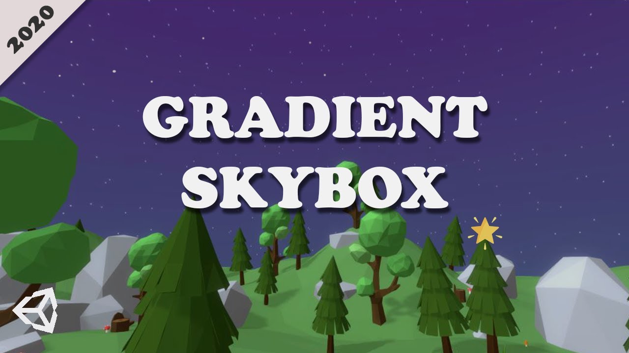
Hello, I'm trying to make stars in a sky box shader but I get this weird smear around where z=0. I didn't find anybody with the same bug and don't see what I'm doing differently than example and tutorials I found online

This is my shader graph

Are you following a tutorial? Can you share the link?
Yes, this one: https://youtu.be/yw2J9NWRdow
Consider donating to help me keep this channel and website alive using :
https://paypal.me/supportTheGameGuy 💖
or
Support me on patreon : www.patreon.com/the_game_guy 💖
I have been learning about shader graph and its kind of amazing and we can do whole lot of stuff using shader graph and I started with a simple gradient shader for my skybox ...
I only changed the noise function
It's my first time using shader graph in Unity but I have a bit of experience with those of unreal engine
Did you try playing with tiling of the uvs?
Yes, the noise moved but the smear stayed in the same place
What if you change the noise scale? Does it affect the smear?
No
Does it happen with the voronoi noise too?
What change is if I modify the world position before the tiling and offset nde
Yes that's why I tried something else in the first place
I feel like if the world position received by the shader is wrong for some reason
I wonder what values are passed for world position, since it renders as the background...🤔
All exemples I found online used the world position this way
I don't know if it change anything but the project was not in urp at first
Wouldn't the stars move with the camera this way?
No. If I get it right, the far plane is just used to get the z position of the world position
I'm not sure how it would work but I'll look into that tomorrow
@slow blade This article speaks of something similar. Stretching at certain points. Maybe you can use part of it for sampling the position.
https://medium.com/@jannik_boysen/procedural-skybox-shader-137f6b0cb77c
I have ran into that problem as well. could not find a way around it. the uv projection is just weird in unity. I think the work around is to go with triplanner mapping but that is a bit of a pain.
Hey 👋 Can be reflections anyhow adjustet from the shader itself?
[URP] - 11.0.0 - ShaderGraph LIT shader

For example here, there's a reflection probe and i'm trying to make the white spots (the reflection) make green
You can get the reflection by using Reflection Probe node but on lit shaders, those reflections are calulated internally and I'm pretty sure you can't manipulate them (atleast not easily). If you're making unlit shader, you can get the reflection using that Reflection Probe node, manipulate the given color and use that to calculate the color of fragment but it seems that's not the case. Correct me if i'm wrong but from my experience I'd say it's not possible to manipulate reflections of lit shader.
I think what you want is Specular map
I'm not very familiar with Specular maps... If I'm not mistaken specular map is not way to manipulate the reflection itself but tint it with some color am I right (or does it tint only the shine that comes from lights)? If so, yes, it can be used to make the reflection more greenish.
afaik specular maps are usually grayscale(storing 1 value in 1 or all channels) that defines the reflectiveness of the materials at certain uv point. So, for example, if you have a texture of a floor tile that has both metal and concrete for example, the concrete part would have a value of 0 in the specular map, while the metal one would have a higher value(possibly close to 1 depending on how reflective you want the material).
For the standard shader with specular setup, it seems like the specular map is supposed to be packed into the alpha channel of the main texture.🤔
https://docs.unity3d.com/Manual/shader-NormalSpecular.html
Ah. My bad. That's for the legacy specular shader I guess..?🤔
The standard one seems to have a separate slot for the map.
My attempt to create procedurally generated stylized/toon rock shader... This would be very handy
The texture are just simple noises and parallax mapped
looks good!
so im trying to have a 2d game like a .. sigh .. LIKE a metroidivania imagine, but with 3d models for the characters as its way easier to animate them
i just took a blender course so i have a 3d model to test out, but, using the (2d preset) URP, with a new URP>Lit material, only the base color map seems to change the character at all. i have metallics, normals, and rough maps but putting them in the material does nothing. halp!

Hey thanks for the reply 👍
Potentially i would be happy to disable the internal logic and then implement the probe myself (via the siad ReflectionProbe node).
Only solution that doesn't require custom base shader would be to disable the probes somehow, but i'm not sure how they work.
If they would be a keyword 👍 that would be awesome. But that doesn't seem to be the case.
https://forum.unity.com/threads/anyway-to-disable-environment-light-inside-my-shader.522659/
https://forum.unity.com/threads/turn-off-receive-shadows-on-custom-pbr-graph-lwrp.657814/
I'm bit afraid to implement Smoothness in Unlit myself, but that would solve many issues indeed 🤟 Ty for the direction.
2d preset wouldn't work great with 3d models I imagine.
What's the problem with using the 3d preset?
my game is 2d..? idk, i don't really remember adding it at this point
honestly i was just referring to how my project was set up, i didnt know URP had something specific
URP has a 2d preset for 2d lights. It's still experimental though. I assume that you're using that preset.
yeah, i thinhk ima swap off of 2d lighting entirely
its too experimental and the pitch shadows don't look good
i have no idea how im gonna do proper lighting, but thats a problem for a different dayt
You should decide if you want to use 2d or 3d assets and switch to the appropriate renderer. Combining both might require you to write a custom render pipeline.
If you care about lighting and shadows that is.
true, i just cant imagine 3d shadows looking good on a 2d game like how would that even work
ori did it .. i wish i could have a copy of the ori proj file so badly.
Hey guys 🙂 Can someone explain the distance node to me? I expect it to work differently than it does. I'm using this simple shader on a sphere and would expect the point at (1 | 0 | 0) to be pitch black, because the distance node checks for that point exactly and the distance should be 0?
However, when I look at the shader on my sphere it's a lighter gray without having a point fully black it seems. Why not?


Does the sphere actually overlap the point in the world at (1,0,0)? It's hard to tell the scale from this image
It's a unit sphere sitting at world origin
Ah, because the radius is 0.5 not 1
i've tried changing it as far as i can remember, so i created a new pipeline asset without using the 2d stuff. when putting it in the project settings, nothing seemed to change
It's not supposed to go in the project settings. It's not the rp asset, it's the renderer asset that goes into the rp asset afaik.
oh, weird
idk it looks right
project settings > graphics > scriptable render pipeline settings
is where i put it but nothing changed so you're prolly right
As I said, that's the RP asset, not the actual renderer asset.


This is what I'm talking about

But it seems like it's already 3d(forward) renderer.🤔
yea i just made a new one for it
Do you have a 3d directional light source in the scene?
And your normal maps still don't work?
in the screenshot you can clearly see something is lighting him up from the top right
but nothing's doing that, moving every light source to his left doesnt change it
If it's a directional light then moving it won't change anything, you need to rotate it
What do you have in your hierarchy?
its a point light
Try disabling them instead of moving.
yeah ive done that not
nothing
ill try moving him now
i tried moving him super far to the right and it didnt change. i guess there MUST be some sort of global 3d light somewhere, but the closest i have is a disabled global 2d light
Take a screenshot of your hierarchy.
If you change settings on the 2d lights do they still affect things? If so the renderer might not be assigned properly
ok! would you like me to search through every component or something
yeah the 2d lights work as expected on everything except the 3d model. which maks esne
So you're still using the 2d renderer.
Well in 3D Renderer the 2D lights shouldn't work at all

The wrong URP asset is probably assigned in project settings. Each quality setting also has an override for it which you should check
which render pipeline asset is actually assigned in the graphics settings?
the one i took screenshots of
under "scriptable render pipeline settings", if that's what you mean
ive tested the orc in a new project with the 3d preset and he works as intended
Take a screenshot of your quality setting with the current quality level selected.
where do i see that?
Project settings - quality.
...
😔
that had 2d listed, damn
ty guys lmao
works now
or at least it changed and the orc is dark and there are no more 2d lights
i do have one more question
ttying to make it like the 3d test project (using an autodesk interactive shader so that i can use my roughness map) just makes the orc come out pink with URP
is there a way to make URP read a roughness map, or should i just go without for all my future models?
i'm illiterate. i found it lol, dw (question answered)
Haha, found a solution. Specular workflow allows to Color the reflection 👍 💪
hey, boring part of the shaders. anyone knows some bit about shader variants ? let's say I have a shader with following keywords system ( an imaginary system )
#pragma AAA key1 key2
#pragma BBB key3 key4
where the final variants would be
key3
key3 key1
key3 key2
key3 key1 key2
key4
key4 key1
key4 key2
key4 key1 key2
so from BBB only one can always be active ( a.k.a. defined ) and from AAA all possibilities should be possible
how to achieve that ?
or in a real example :
I have
IS_GUASSIAN
IS_MASKED
QUALITY_HIGH
QUALITY_MID
QUALITY_LOW
as u understand, all the QUALITY_* should be available in the final build because the quality can sure change. but other keywords could be optimized away
guys
i cant edit the node for color in the shader window, when i click on it it just selects the master node
Hello everyone sry for that but I have several questions :/
https://stackoverflow.com/questions/54739349/unity-2d-area-color-inverse-effect/69708377#69708377
Is this possible with shader graph ?
Is it possible to use the alpha channel of a texture rather than the mesh ?
Thanks.
Stack Overflow
I am trying to create a GameObejct that if active reverses the colors of anything behind it. Ideally, this GameObject expands from its centre point to a certain size radius when it appears/becomes ...
I understood how to modify a "texture" with shadergraph but I can not do this kind of effect area through sprite
Pretty sure shadergraph has InvertColor node.. never used it or knew if thats the node you're looking for

this invert the color of a sprite but that not what i want, i want to made a effect that invert color trough a texture
You'll need to sample scene color or something if you want to invert everything else.
There's a scene color node
Although it's not the same way they did it in the regular shader. Honestly, I don't completely understand how that shader worked, but the important point is the blending mode that it used.
hey guys, can someone help me create a shader that creates a colorable outline around my 3d models towards the camera?
I just made this.. pretty simple actually.. give it a try

https://www.youtube.com/watch?v=MqpyXhBIRSw like this, but with 3d? i really like this effect but after the changeover i have no idea where to go

Thanks to NVIDIA for sponsoring!
Learn more about NVIDIA Studio► https://nvda.ws/38AaA8K
Razer Blade Studio laptops► https://www.razer.com/studio
In this video we create outline effect using 2D Shader Graph!
● Learn more about 2D Shader Graph: https://youtu.be/5dzGj9k8Qy8
● 2D Glow Tutorial: https://youtu.be/WiDVoj5VQ4c
● Get Gothicvania Ch...
strange grey square in my render :/ I will inquire

no no.... dont do that.. see my post above

see that Red turns into green... is that what you want?
@narrow breach
i try
He wants the scene color overlapping the object inverted.
Not the texture color inverted.
np
instead of adding scene color, invert it and feed it right into the color. Nothing else needed.
The simplest way to achieve that is to duplicate the renderer, give it an unlit colored material and reduce it's rendering queue.
sounds cool but also. what
duplicate the renderer?
do you mean duplicate the forward renderer data
oh, i wouldnt call that a renderer
ok so in the material i make
i make it put in the object twice
There's a renderer component, so technically it's a renderer.
oh, ok
so i make a material that takes in the renderer component twice .. make it render one of them last in an unlit colour ..
can i do this in shader graph?
Yeah, you just parent that "duplicate object" to the real object and do everything else that I described.
No shader graph involved.
oh. what
It's just a duplicate object that is rendered behind the real one with one color
so every time i make an object i have to put two renderers on it
i'd prefer to do it in a shader/material if possible
Well, if you want to go the simple way, yes.
im working on something quite big here so id prefer upfront time sink for future ease of use
I imagine it shouldn't be too complicated with a shader graph either.
sounds better, hah
the "scene color" node don't work like i want x|

You just need some way to extrude the object edges along the normals and color them in whatever color you want.🤷♂️
alright that sounds good
is the shader transparent?
The shader graph needs to be transparent. You're using an older version of the shader graph, so I'm not sure where that setting is...
oh
like a PBR graph ?
I don't know if PBR can be transparent. Is there anything else?
It probably can though
Actually, thinking about it, it should've worked with an opaque shader too.🤔
Make sure that the rendering order of your inversion material is higher(later) than other materials in the scene.

I think I know what might be the issue
Take a screenshot of your render pipeline asset


enable opaque texture and see if it works

don't change anything :/
Hmmm... Then I guess your shader is not transparent. What unity/shader graph version are you using?

Ah, okay, so it is transparent
Note: In Universal Render Pipeline this Node returns the value of the Camera Opaque Texture. See the Universal Render Pipeline for more documentation on this feature. The contents of this texture are only available for Transparent objects. Set the Surface Type dropdown on the Material Options panel of the Master Node to Transparent to receive the correct values from this node.
Take a screenshot of your camera inspector

Just to be sure, set the opaque texture to true
The last thing that I can think of is inputting screen position into the scene color node input
don't work 😢
Or try the UVs for a test
UVs ?
Yeah, the object uvs. Although that's probably not gonna change anything. I think the problem is with the rendering order.
or this

ah yes it's doesn't work :/
And if that doesn't work, then it's definitely the rendering order. 99%
how can i change the rendering order ?
in the material settings
i think its because "Scene color" doesn't support URP
.
might also need to adjust the order in the sprite renderer.🤔
Ofc it does
Take a screenshot of your sprite renderer and material
It might also be precisely because of the sprite renderer.🤔

Try a regular mesh renderer with a quad mesh instead and see if that works.
And the sprite renderer?
Yeah, could be the sprite renderer. Try a quad instead.
like this ?

Yeah, just make sure that it's in the right position and all of the previous fixes applied(I see that you removed the screen position node).
The Scene Color node / Opaque Texture doesn't work with the 2D Renderer
Aha. I thought that that might be the case, but it wasn't mentioned in the docs...🤔
ok i try smtg
ok final question


so this "handmade" shader work properly but Is it possible to use the alpha channel of a texture rather than the mesh ?
Maybe you can try discard if the alpha value is lower than a threshold. I'm not sure if that's gonna work though.
if(col.a < someThreshold)
    discard;
that discard everything but that a start
what?
put that in the fragment shader
just before you return col
Do you have alpha set as transparency in your texture import settings?


The problem is that you only sample the bottom left of the texture:

try o.uv = v.uv
I'm not sure why it was done like that... Maybe there's an important reason for that but I can't figure it out.
i've worked on this shading thing for a while and ive got an idea buuuut

Add depth to your next project with Outline Shader (URP & LWRP) from Easy Game Studio. Find this & more VFX Shaders on the Unity Asset Store.
can anyone help me make something like this?
i'd like to make my own version for practice and, obviouslty, cause then it wont cost money, and also so its more customisable
but obvs i have no idea where to start
pretty sure, there are tons of this on youtube, heve you checked there?
There are clues in the review: it seems to be relying on post processing
i checked and saw one video that was for 2d.
interesting but also I Am New and have no idea how to manipulate post processing more than the component
if this effect will be scene wide, I'd go with custom renderer...
Pretty sure Unity has an example for that
otherwise sahdergraph
eh, it might be. ideally i'd prefer a material i can put on an object renderer to apply the outline
ill look for it on YT again
oh thats right, yeah i saw theirs but it didnt work with URP
Unity has some examples which includes a outline shader like that. (It's also where the character model in the video is from too) https://github.com/Unity-Technologies/UniversalRenderingExamples/blob/master/Assets/_CompletedDemos/ToonOutlinePostprocessCompleted/Shaders/ToonBasicOutline.shader
Can put it on a MeshRenderer as a second material
The same example has a post-processing sobel version too
Heyy..
I have no idea aboutr CG shaders but i hope someone can help me out! I found this shader many months ago and it works fine.
But if i scale my object past its original size, the outline breaks and has cuts... (im not sure how to explain it, but the screenshot should make it apparent.)
Does anyone know a good way to fix this? Heres the shader:
https://mystb.in/CopyrightsHarvestSubscribers.properties

ah here it is for custom renderer one https://github.com/Unity-Technologies/UniversalRenderingExamples
Outline shaders like this only really work well on models with smooth shaded normals. (Or find a way to bake those normals into other uv/vertex colours and use those for the outlines only)
you just said words that are way over my head my friend
these are Synty models
and i cant remember where i got this outline shader from, was atleast 8 months ago
Do you think it would work if we pass the normals into the fragment shader and normalize them there, then use that for the outline position/thickness?🤔
im overwhelmed for today haha
ill prolly just buy that package tomorrow
ty all for your help todayu
look at the reviews first. The only positive ones seem to be from those that got it for free. And honestly 15$ for **that **is too much. There's a free version of a similar asset that's way better.
The direction of the normal would still be wrong, so still create gaps. It needs normals that can be shared between all vertices in the same position. The model is flat shaded so has different directions though
i tried that one and it does look good but it just .. doesnt work
I see. That's insightful.
idk why. plus, its not a material i can just add on although i guess thats not too much difference
So we saying im outta luck?
Well, if you couldn't get this one working, chances are the other one wouldn't work as well... As I said, check the reviews on that asset.
fair nyff
Since my knowledge on CG shaders is less than 1%
wdym?
wdym wdym? I dont know anything about scripting shaders, So i am none the wiser to know how to fix it
Or atleast band-aid it
if at all possible
Ah, sorry. Misread your message. xD
Weren't you using URP though?
I am using URP yes
Then it's not CG. It's HLSL😛
Check out this tut. https://www.youtube.com/watch?v=74AS5DmLe8w
Thats alot of engine editing just for a little thing like this
outline is a pretty big deal. I wouldn't call it a little thing.
how can i write .compute code and some editor behaves a little more helpful than a texteditor?
There's an hlsl plugin for VS that is a little more helpful than a plain text editor.
As for how you write, well, you just write it.
Is there a simple way to fix what i already have then? Or no? I can't imagine Synty releasing these models if they cannot work with an outline shader
Why not? Why would they even thing about something so specific? Besides, there are more than 1 way to implement an outline.
Where should one start to look for writing shaders? I'm a total noob, I had a class of old and simple OpenGl in past but that was that, I'm wondering if it's feasible with a reasonable effort to write some sort of flickering/trail effect for a 3d mesh or that would require too much time, since I don't have plenty, doing all things by miself
@kind juniper thank you it works perfectly
I'm not at all experienced with writing shaders in code, but i needed a billboarding shader and for some reason this works but also flips the sprite on it's head
OUT.vertex = mul(UNITY_MATRIX_P, mul(UNITY_MATRIX_MV, float4(0, 0, 0, 1)) - float4(IN.vertex.x,IN.vertex.y,IN.vertex.z,0));
in the vert function
anyone know why?
and how i can achieve the desired result?
Mvp Matrix calculation... I think it'll be easier to just flip the uvs lol
don't really understand what you are saying...
You need to flip the uvs. In the fragment shader do uv.y = 1 - uv.y before sampling the texture. I think that should be enough.🤔
thank you very much :)
worked
Remember that it's a workaround and you should really find the proper solution with the matrices...😅
yeah lol, probably gonna use a shader graph solution i found
a lot of people are having problems with this
from my research
thanks!
It depends. If you stick the time node into a texture sample that isn't in wrap mode then it would be horrible and not work but most of the effects you're gonna use that for are procedural and are basically functions with their domain going to infinity so you can manipulate the UV however you like. At least that's my take on it.
Hiya, I'm trying to create an effect like this. I have a shader which allows me to draw a texture in photoshop and adds emission, but I was wondering if there was a better way to animate different textures, as at the moment I am constantly rotating different materials with different textures, which is seriously affecting perfomance. Any ideas?

I thought Ubit meant the facial animation
but it could be that small display below too... bottom line is... question is just too vague
Yeh sorry I meant the facial animation
I can do the trail
But yeh atm I've just got a texture for each expression and a corresponding material which just cycles through
Probably a terrible way to do it
could do effect like that with gradient mask which you then feed the mask threshold value in shader
But I wanna animate loads of expressions
like, you could control how much the mouth and eyes open through that

you have a gradient mask, in shader you compare when the color value is over your treshold, if it's over, you give it emissive color, if it's under, you draw it black
you can add smoothstep etc to make the border smoother too
this is essentially how SDF rendering works - if you know of that Valve's text rendering paper
So I set my texture to be the gradient mask?
No idea I’m very new to shadergraph
Thanks for the tip though I’ll give it a look
basically imagine you'd have something like this for eyes (I just put quick linear gradient but you could make it round etc)

then when you check is the value is above or below the value you want, you draw it black or white for the mask
after mask you get eyes half way through
Can u do this in shadergraph?
if you need more expressions, you could have one 4 channel mask texture with different gradient masks which you could then mix and match on shader
@iron vine instead of multiple textures, you can also use sprite sheets; the flipbook node makes it really easy.
you guys know of any extensions for VS to work with .shader?
and recommend this one?: https://marketplace.visualstudio.com/items?itemName=DanielScherzer.GLSL
Extension for Visual Studio - VSIX Project that provides GLSL language integration.
Includes syntax highlighting (file extensions: glsl, frag, vert, geom, comp, tesse, tessc), code completion (OpenGL 4.5 + identifiers in shader file), error tagging with squiggles and in error list (error list support is ve...
I think CG is closer to HLSL than GLSL, and in SRP you have HLSL anyway, so it's probably better to look up an extension for HLSL..?
Extension for Visual Studio - Enhanced support for editing HLSL in Visual Studio
this?
works well for compute shaders
Yeah.
thanks
Hi everyone, I'm following a tutorial (found here: https://www.youtube.com/watch?v=84rZ-rCRsZk&ab_channel=DanielIlett) for making sprite outlines with Shader graph. The problem is that it only draws within the boundary/canvas of the sprite itself, and for pixels that sit flush against the borders there are no outlines. (Keeping the sprite flush to the edges as much as possible are required for the project though)
I tried changing the vertex positions and clamping the sprite to the center so the bounds would be larger and allow for more outline thickness as it grew, but I ran into all sorts of problems which I couldn't solve. I'm very new to shaders (and shader graph), so I'm quite stumped tbh lol.
Any help or direction would be much appreciated, thanks all.

Create an outline effect in 2D for SpriteRenderers using Unity Shader Graph! You can also read this tutorial here: https://danielilett.com/2020-04-27-tut5-6-urp-2d-outlines/
💻 Get the source on GitHub:
https://github.com/daniel-ilett/2d-outlines-urp
✨ Get the "Bandits - Pixel Art" pack on the Asset Store:
https://assetstore.unity....
here are where the outlines are to appear

Hey guys, I am trying to lerp between different materials based on time of day. I want to do it like this guy does it: https://youtu.be/ERA7-I5nPAU
He basically has one script that controls his daynight cycle and has different materials assigned to different times of day, and then he has a folder with the ones that he assigns to different models and they change depending on the time of day. How does he do it?

Date of Recording: 2020-11-14
I took a bit of a break from the usual tech updates this week to record a making-of video detailing what it's like to create a scene from start to finish in the Unity-based pixel art game engine I've been developing.
I found some neat modifier stack tricks in Blender for creating procedural, non-destructive detail...
I am gonna screenshot it, but how would you go about doing something like that?

the daynight cycle contains materials for all of these ones
but in different colors
for different times


he doesn't have to change the materials by hand, he assigns the coloured ones here and then has ones in the files that change depending on time of day
how
does he do that
i know but how does he lerp the material that was assigned in the inspector
he has sepperate materials that are assigned to objects and then lerped
maybe sharedMaterials?
I don't quite follow
sorry, gonna try to explain again
He has materials that are designed for different times of day.
He assigns them to a script

like this
then he has sepperate materials
that he assigns to his objects
and they change
depending on the time of day
I'm pretty sure the script overrides the materials assigned to objects
but he doesn't have references to those objects
in the script
it's in a sepperate object
DayNightCycleController
Where's that in the video?
Yeah it's a good question
I'm not entirely sure how he did it
Probably there is a better way than finding each object to lerp
But if it was modifying shared materials, it probably wouldn't be using pre-existing materials
to switch to, I mean
hmm

hmm
do you think i can assing a material to this?
or can i only modify it
@grizzled bolt
I think you can just reference the materials that need to be lerped. Not the objects. Then do the lerp thing on them at runtime.
but will they be changed if they are assigned from the inspector?
Yes, for sure.
so to be clear, what you mean is that the script should have inspector slots for the materials that need to be changed and the custom materials
The renderers I. The scene still reference these material assets. Assuming you don't create instances of them, they should change with the material assets.
The materials that need to be changed and the lerp target materials, yeah.
and then how do i change the materials with lerp? if i do :
Material custommaterial; // assigned in inspector (to be changed)
Material lerp1;
Material lerp2;

custommaterial = Material.Lerp(lerp1,lerp2,0.5);
won't this just change it in the script
won't it just generate a new one?
or do i have to call the function on the custom material?
custommaterial.Lerp(lerp1,lerp2,0.5f);
material.Lerp is not a static method. The way you do it above, should cause a compiler error.
It also does not return anything. It chages the material that the method is called from.
is there a way to add fog with another pass so I don't need to mess with my main shader?
That'd be convenient
Though I can't quite wrap my head around how will the method change the materials themselves when it's ran on a renderer component instance
Guess I'll try it out
Does it not just lerp all of the material properties?
You can do fog in a post-processing pass. Usually depth based, but can also be volumetric or whatever.
The price you pay is having to do a post processing pass with whatever calcs are necessary.
Tried it, it leaves the original material unchanged and only affects that specific renderer component
So if day/night cycle is done that way, the cycler script needs a reference to every object's renderer to apply the lerped change, I suppose
Using some system of shared materials seems way more convenient
Were you accessing the .material or .sharedMaterial?
There is no sharedMaterial.Lerp, is there
Why not? shareMaterial returns a Material all the same. It's just the one that's in your project folder as opposed to a new instance.
How would you use material.Lerp to modify a material asset?
the same as with renderer.material, just renderer.sharedMaterial.🤔
renderer.sharedMaterial.Lerp(matA, matB, t);
Oh, I assumed the method didn't exist because there's no article for it in documentation
It's the same method though. sharedMaterial returns a Material just like material. No difference at all.
Oh yea it does work, even if modifying assets live is weird
I'd rather use global properties than mess with altering the materials
Especially if there needs to be logic for meshes with more than one material
but if i assign a material to a script, you cant access a renderer
so no sharedMaterial
You don't need to.
As I mentioned previously, sharedMaterial is just a reference to the material asset, so you can reference it directly.
so does this work or not?
i haven't tried it yet
It should.
ok i'm gonna try it
@violet bough
{
    // Blends between two materials

    [SerializeField] Material material1;
    [SerializeField] Material material2;
    Renderer rend;

    void Start()
    {
        rend = GetComponent<Renderer>();
    }

    void Update()
    {
        // ping-pong between the materials over the duration
        float lerp = Mathf.PingPong(Time.time, 1f);
        rend.sharedMaterial.Lerp(material1, material2, lerp);
    }
}```This is the test script that worked
The renderer itself uses material0 as its material which gets permanently overwritten regardless of what it looks like once the script runs
doesn't
Show what you did.


And Your terrain component? What material does it have?


Does it have it at runtime too?
yes
Hmm... Well, I'm not sure about terrain, but have a try with a mesh renderer. Maybe terrain creates an instance of the material anyway.🤔
Weird. Are you sure that your code runs?

okay
Can you take a runtime screenshot of the renderer that has the material that you expect to change?

This doesn't look right
It should bounce between 0 and 1 every second
that's every frame
Ah, of course
i can confirm it does go from 0 to 1
Works for me
what did you do?

public class MatLerper : MonoBehaviour
{
    [SerializeField] private Material target;
    [SerializeField] private Material matA;
    [SerializeField] private Material matB;
    void Update()
    {
        var t = Mathf.Sin(Time.time);
        target.Lerp(matA, matB, t);
    }
}
could it be that it's on the same entity?
Gonna try with ping pong
That doesn't matter. I reference the materials from the project window
Yep, works with ping pong too
Just to be sure, your DayTerrain and GoldenTerrain mats use the same shader, right?
yes
Okay
they only use a different texture
well it samples the texture for a pallete :/
rip, at least we got to the problem, thank you :)
ok @kind juniper tried it, it works now
hmm
but for some reason
not with terrain
I guess terrain instantiates the material at some point.
Might need to access it via the terrain.
yeah i'm probably gonna just get a refference to the terrain
I wanna ask something about compute shader
The boundsize passed in is a float,How does it calculate in float3?

@clever saddle If it works, then I'd guess that it implicitly converts it to float3 with all components having the same value.🤔
Does it work?
@kind juniper Yup.It works.For example,if the boundSize is 2,it will convert to (2,2,2),right?
That's what I assume, yeah.
hey folks. Is there a way to reference a cubemap without 3d geo? I'd like to have a screen noise overlay that's in 3d space, so that when I rotate my camera view, it doesn't feel like noise on my glasses/visor. Right now the world moves in relation to the camera but the noise does not. But figuring out how to talk to a cube map in shader graph is beyond me. Any advice?
was trying to delve into writing shaders, making a circle with smooth edges,
fwidth works when you got close, but would be quite jagged from far, so i capped the val, (with min) - which kinda worked. .
i was wondering if i should use proximity (VPOS) and multiply it based on z value or something?


i have just fixed a problem in my code
because
for some reason
uv of 1,0 is = 0,0
so i can't clamp to 1
why?
why isn't a uv of 1,0 on the right of the texture
anyone here know how to pass uniforms to shadergraph?
Properties on the blackboard are going to be uniforms. Like, say, a float or a color (float4).
How the result is returned depends on the wrap mode and filter mode the sampler is in (and texture's default is a property on the texture import settings too).
Clamp will clamp to the edge, even smearing pixels to the edges (often results in people getting confused with "lines" in their textures...seen often in sprites).
Add to this the filtering mode that samples nearby pixels, and if they wrap they wrap. So the nearby pixel to 1.0 is going to wrap to 0.0, and then the two get computed together and "blurred".
Best guess, can't tell squat from that graph though.
Stack Overflow
I'm doing a color lookup using a texture to apply an effect to a picture. My lookup is a gradient map using the luminance of the fragment of the first texture, then looking that up on a second text...
Anyone know how to make a shadergraph shader that works with RectMask2d? I made a shader for my UI icons and they don't get masked by it anymore.
anyone know a way to disable specular effects for an object using a lit shader? I know that sounds odd but my blackhole effect for some reason only works correctly if its a lit shader in HDRP. but I cant get rid of the specular effect on its surface and its breaking the effect

What is compute shader grammer. Anyone know where to check the API?
syntax you mean? Compute shaders are written in HLSL as stated in the docs:
https://docs.unity3d.com/Manual/class-ComputeShader.html
You can refer to the unity manual section on HLSL:
https://docs.unity3d.com/Manual/SL-ShaderPrograms.html
Or the Microsoft docs on HLSL:
https://docs.microsoft.com/en-us/windows/win32/direct3dhlsl/dx-graphics-hlsl-reference
How do I get keywords from script?

Need to know which enum it is currently using in script
You could probably get it as int parameter
You set it on the material. Check the material's value, that's what gets sent to the shader when it is time to render the object.
@kind juniperis correct, enums are ints. But you can compare them to enum constants as set in C# (either created by you, or canned).

any idea why this weird shadow thing is happening?
i'm gonna send my shader code

i use this to get the light values
this is the calculate light function
Pastebin
Pastebin.com is the number one paste tool since 2002. Pastebin is a website where you can store text online for a set period of time.
i am using urp
and these are my setings

hi made a tutorial on how to make a pixelated glitch https://www.youtube.com/watch?v=PpOLr2z-Jus&t=2s

i made a glitch effect in shadergraph for post processing. because i couldnt really find any tutorials, i desided to make my own. if you have any questions: feel free to ask.