#archived-shaders
1 messages · Page 221 of 1
I'm currently integrating 2 assets together and wondering what's the best way to avoid any manual work basically, like redo the uv unwrap
Maybe i can do something in the dye system part, since the customizer from this asset is not really needed
My client just wants the models, basically
But actually, i'm out of the house until tomorrow so, not really in a work env right now
So the color palette technique means u cant do "picture" texture right. Or detail texture (pockets zippers)
But.. what's the point of color palette approach if SMR is not gonna be batched anyways? It just saves using a single texture for all, right, but that's why can't have details
The other asset is the unwraped uv approach (with details)
Yeah, pallet replaces the texture, so you can't add texture details. The point of it is either a specific artistic style(look) that fits well with low poly art style or if you don't use SMR, it can be helpful for batching, while keeping the texture atlas small.
You shouldn't really worry about batching when it comes to SMR. Processing animations is probably way more expensive performance wise than a few more drawcalls.
When you have too much SMR rendered, it's the animation related processing that is gonna create the bottleneck, not the draw calls.
Anyone know how I might modify the screen using a Compute Shader? (aka create an Image Effect using a Compute Shader)
I would love to just use OnRenderImage() and pass in source to the Compute Shader as a RWTexture, but sadly the "source" isn't set as Write-enabled so I get an error.
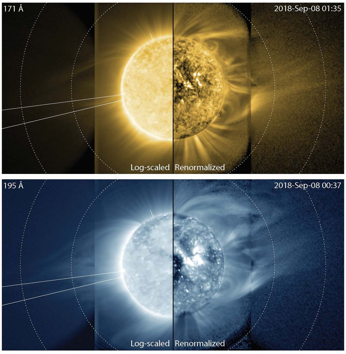
so I am working on a 3d star/sun shader for a space game and I am trying to work out a way to create corona and ray effects around it like this https://cdn.mos.cms.futurecdn.net/7RuEJKBSjY3tUscN9cb6mN-1200-80.jpeg

I know particles are an option, just wondering if I can do it with a shader instead
@stark vessel If not particles, the only alternative I can think of would be raymarching, specifically volume-rendering raymarching. I can give more details if ur curious.
why do all the cool things I want to do require raymarching...
nebula, blackhole gravitational lensing and now star corona.
well I have no skill in programming so I will probably have to wait for any raymarching I guess. no way to do that kind of stuff with the built in nodes in shader graph, right?
ok, new question... is there any way to do something like this without horrible seams? (its an animated noise pattern)

I would settle for a way to make them blend so they are not so harsh
That's the default unity sphere mesh, right? Either use triplanar mapping or get a sphere mesh from blender.
no, that is a custom mesh
Hmm
it is a cube sphere, I think I heard somewhere that unity's default sphere is also one just messed up in many ways
Yeah, maybe look into other sphere types?
I have tried all types, it dosnt matter, any mesh is going to have a seam if you dont have a texture that is seamless.
and as far as I can tell none of the unity noise textures are seamless. so either I need a different way to map it, projection or something or I need a way to smooth the seams enough they are less noticeable.
I tried using using the position node to do view and object projection but those look fairly bad when you move and for some reason dont play well with my custom spheres
Why?
There's nothing really special about a compute shader that I can think of...when doing a post-processing pass. I mean, what's the diff...if you do the calcs in a pixel shader or do some "stuff" in a compute shader? Can you not break your algorythm down into per-pixel calcs? You said you want to "modify the screen"...that's 1/2 automagic in a pixel shader. It outputs to the screen. That's its whole thing, what it is created for.
I mean....the pixel shader context has the "for (x...) and (for y...) already done for you, and you get the x,y out of the screenpos in the vertex stage. Just process pixel x,y and you're gold.
So maybe if you need a compute shader, you'll have to describe the specific needs. But you can use them to modify a render texture.
There is no perfect mapping of a 2D texture to a 3D sphere. Ask any cartographer. 😉
So I agree with @kind juniper, an icosphere is probably your closest match if you want evenly distributed verts, but it won't be perfect, even if you find seamless textures. A UV sphere, OTOH, properly mapped may work if your texture is also designed for it (think maps with those cut-out parts in them when laid flat) Triplanar mapping may be a better option, depending on your needs.
none of this is a problem if I was mapping a texture to a sphere, I know how to do that just fine. the problem is I am trying to do this with shader graph. its not like I can have a 4k animated texture for the surface of these stars, it would be huge. so I need to do it in shader graph with an animated noise texture. at least that is the only way I can think to do it
yes
well I might end up with a base texture under it for detail, undecided if that is going to be needed or not
OK, well it's really the same thing, in a way. But instead of doing a tex2D read, you're getting the result of a computation.
I am used to doing this stuff in blender and it just magically works
You can always compute the vector from the center to the world-space (or object space) point, and somehow (after you normalize it) decide on where to generate your noise lookup. Kind of like tri-planar mapping using normal vectors.
But IDK why your noise isn't seamless...seems like it should be, as you say.
I'm looking for a sketch-effect. My ultimate goal is something that looks more detailed over time. Any pointers? My own search brought me here: https://developpaper.com/unity-shader-for-sketch-effect/ but I'm not sure if this is even possible with shader graph. I also don't know if this is the best approach to begin with.

In this paper, we share the specific code of unity shader to achieve sketch effect for your reference. The specific content is as follows This is the unreal rendering in Lele’s book. The algorithm is very interesting. If you are interested, you can have a try. The basic principle of sketch effect: first, draw the […]
how can I get these 3 colors separately in shader graph?

I would try using color mask or what?
Are they always at the same location?
Can you not just sample them at the three points?
Like UV (.5, .5) would be the center, and somewhere along (.5, .98) would be the "top" color, and (.5, .02) would be the bottom color.
Or does the texture change? And if so, how do you know where to sample?
I have a 3d model that I spent all night working on that looks absolutely fantastic on a PC build, but the moment I transfer the build to Android it looks.. different. My normals turn from blue yellow and don't render correctly. Is there any way to prevent them from getting all compressed?
btw here's before


There's android
I'm on Unity 2019.4.31f1.
I keep hearing about a way to just disable DX11 to solve the problem, but I don't have that option on this version of Unity (At least not that I can find. Maybe I'm blind or something.)
why my object still is black? im i wrong somewhere?

Why?
There's nothing really special about a compute shader that I can think of...when doing a post-processing pass. I mean, what's the diff...if you do the calcs in a pixel shader or do some "stuff" in a compute shader? Can you not break your algorythm down into per-pixel calcs? You said you want to "modify the screen"...that's 1/2 automagic in a pixel shader. It outputs to the screen. That's its whole thing, what it is created for.
@meager pelican The diff here is that Compute Shaders support RWTextures and pixel shaders dont. (Basically Im rasterizing vertices. Im running the CS once for every vertex, not once for every pixel. Each CS program writes only to the relevant pixels). I mean I could just render to a quad in front of the camera, but I was hoping there was a more direct/less wasteful way to do it.
i think it just looks like that because it’s reflecting the skybox
Doesn't look like you're using a sprite shader graph
Note the little warning here - shaders need to conform to certain things to work properly with SpriteRenderer

Checkout this project for a sketch effect implementation. https://github.com/chrisloop/White
Checkout their other repos, they all look amazing! https://github.com/chrisloop/URP2020ToonShader2
Holy cap that looks amazing
Thanks a lot
I didn't know the term post processing in combination with shader graph was a thing. Sounds heavy
is there a way to bring in a game objects physical position as an input in shader graph? I don't want the individual world coordinates for each point on the model, just the xyz of where the gameobject itself is. I have a shader and i'd like to use the model's position as a seed for the random noise so that if two objects are right next to each other with the same shader they don't look exactly the same
and now this go all white, do u know why?

So I have this shader and I'm trying to get the _Glossiness to change over time, but stop at a certain number and restart the cycle (or go backwards). I've tried using if statements and for loops and nothing seems to be working. Also for some reason the values don't change on the slider in the inspector in editor so I honestly have no idea what is going on https://pastebin.com/RN4NVryE
Pastebin
Pastebin.com is the number one paste tool since 2002. Pastebin is a website where you can store text online for a set period of time.
Well, I'm not sure I fully understood that, I'd think you'd need 3 verts for a polygon, then rasterize them somehow. But...OK.
I think you can write to a render texture directly, then output that via a blit to the screen later. If that's what you want to do.
Or maybe look into drawprocedural and variants, where you can use a compute shader (perhaps with structured buffers) to generate a mesh computationally and then output the results.
If you set the value on the C# side of things, and just pass it to the shader, you can use:
https://docs.unity3d.com/ScriptReference/Mathf.PingPong.html
Of course, that goes from 0 to N, and you can offset it from there to be A to A+N. It will bounce back and forth if you pass it a scaled time value. So speed is a function of time * rate passed in.

As far as setting it on the shader goes, you'd have to show your c# code.
@umbral hemlockAnother thing I thought of (remember I don't know your exact use-case) is that a stencil will let you pick-off certain pixels, and not "process the whole screen". The pixel shader will only be called for those pixels that pass the stencil test.
If you're using a RWTexture, you're probably going to end up blitting the whole dang thing back over "to the screen" anyway. Processing all pixels.
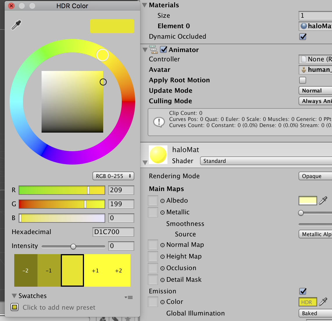
how do I change the intensity of the EmissionColor through code?
cuz I know how to get the material but should I use SetColor then? and if so, how?
cuz that doesn't contain an intensity parameter afaik
Unity Forum
I want to programmatically change a material's emission color intensity. How do I target this via script?
[IMG]
anybody know if Unity's Built in Decal Projector for HDRP has a limiter to not project on backfaces (or knows a good workaround)?
@meager pelican when I do ```cs
LightMesh = MicrowaveContainer.gameObject.GetComponent<Renderer>();
LightColor = LightMesh.material.GetColor("_EmissionColor");
I get the right color, but it shows black in the editor and doesn't show intensity
this

Try using .sharedMaterial instead.
Also, since I see "is microwaving" in that (mostly covered up) list, I assume that's a custom shader for that material, so emission colors are HDR colors, and you'll have to specify it that way (I think). At least they are in the standard shader.
And your light color looks to be black, so if you're multiplying colors by that you'll get black.
Oh, OK.
IDK, maybe it is getting an intensity of 0 since it's not HDR (total guess).
Or maybe I just have no idea what it's doing (likely).
But I'd try HDR.
Is the left side the current color or the "new" color? I forget off hand.
Try adding HDR to the shader property.
Also you didn't show me the set code, you showed me the read-code. But don't use .material in the setting code unless you're trying to clone the material.
how do I store an HDR?
oh okay
Put [HDR] in front of the property in the shader.
Let me check the C# side, sec....
why would I put that theere, when in the shader, it's already an HDR?
thee color in my c# code is just a normal color that can't store intensity
it's the shader that's an HDR that can store intensity
Well, in the graphic you posted, that's not an HDR color picker.....
In the C# side, there's a colorusage attribute, if that helps any.
I think the HDR color is actually just color * intensity. And they have an attribute in the standard shader for intensity, so they can divide it out and get back to the normal color.
So a double intensity red with 1 alpha is (2, 0, 0, 1)
yes this one comes from the c# color, not the HDR from the shader
I am just using the standard shader here
but...the standard shader doesn't have "is microwaving" in it.
Confused by what you're saying vs what you showed in the pic
what you're seeing there is a completely seperate script
ur just seeing the components on an object there
the Color u see is from a script attached to that object
no
Well, it's probably confused between being HDR and not-HDR. Firstly, I'd make both HDR.
What does it look like if you inspect the material itself? Can you make an instance of it, or while running, inspect it in the editor?
Not the C# gameobject, the material object.
wait u can make an HDR in c#?
I just posted an attribute link for that above.
oh mb
np
public Color foo = new Color(.5, .5, .5);```
I think.
Then your color picker in the inspector should be an HDR color picker.does the .5 .5 .5 matter?
oh.
You might also try adding
myMat.EnableKeyword("_EMISSION");
to your script. IDK if it will matter if emission is checked on the material, but it might be worth a shot.
Dammit.
I'll have to fire up Unity and play around with it.
So to understand...
You have an object, you want it emissive, and you want to set the intensity in script, right? But set the color in the inspector.
And you're in the built-in pipeline.
@crude bolt Yes?
nono I just want to get the color of an HDR
that's all
the other stuff I have figured out
but I just want the color of the HDR without the intensity actually, but still havee it be what the color acxtually is
Well do you know the intensity value?
Divide the color by the intensity.
It's a pow function, see post way below
I do not know the intensity
Because when they set it, they multiply the color by the intensity.
hmmm wait I do
Yeah.
And that's also why it has to be an HDR color....
Why can I not edit these values?

what object are they applied to?
is it a prefab or just a object you pulled into the scene?
I pulled an fbx model into the scene and applied a texture
make it a prefab
and apply your own materials in the original fbx

if your object has materials (like the fruit ones in your example) then you can use "Extract Materials" to automatically generate them
How do I make it a prefab?
drag it into the project folder

original
should work for the moment
Did you extract the materials?
(should have told you to extract them first since your object might turn pink now^^)
I tried extracting them, but nothing really happened
So I tried to manually assign materials here

I then chose this material, which I maybe shouldn't have done


thats odd. can you show the full unity screen so i know exactly what you have selected there?

thats really odd
oh wait
click on the prefab fbx in the project folder and show the Material tab in inspector again
seems like you don't have created your own material yet

So this didn't get converted to a prefab

lets make it correct this time:
1.delete the object in scene and the prefab.
2. then go to the fbx and to the material tab.
3. there click "Extract Material". a window should open where you want to save the materials (choose where you want them, it needs to be inside the project),
4. then drag the fbx into the scene
5. drag the fbx back to the project folder tot create a prefab
What is the best way to make a shader that can use vertex colors so I can use it with generated meshes?
I can't delete this

you don't need to
that is the material of the actual fbx. it is just a reference that is part of the fbx and can't be deleted.
only delete the prefab from the scene and the one you made in the project folder (which is pink)
we want to start the actual workflow fram scratch
original again?

yes
donezo

have you extracted the materials before that?


perfect ^^
Beautiful

@crude bolt
I got it! Found this link (See bottom comment/post):
https://answers.unity.com/questions/1652854/how-to-get-set-hdr-color-intensity.html
Here's the script I used to verify it. It's odd stuff.
The intensity calc is a Pow() function, and there's a way to reverse it.
I used an intensity of 3.1 in the inspector, and got a 3.1 value back. However, getting the base-color value back is more complicated, due to the way the color picker sets the color vs sets the intensity. You can set the color values above 1.0 and also set an intensity scale above 0 at the same time and things recalc. I found it less confusing when I switched to RGB (0-255) mode.
See the 2nd to last post in that same link above for more formulas if you need to calc the base color back out of it all too.
    private Material myMaterial;

    void Start() {
        myMaterial = gameObject.GetComponent<MeshRenderer>().sharedMaterial;

        Color eColor = myMaterial.GetColor("_EmissiveColor");  // These should be PIDs but...meh...testing
        Debug.Log("Emissive Color is " + eColor.ToString());
        //float intensity = myMaterial.GetFloat("_EmissiveColorIntensity");
        float maxColorComponent = eColor.maxColorComponent;
        float scaleFactor = 191.0f / maxColorComponent; // 191 = k_MaxByteForOverexposedColor Unity constant
        float intensity = Mathf.Log(255f / scaleFactor) / Mathf.Log(2f);
        Debug.Log("Intensity is "+intensity.ToString());
    }
Unity is the ultimate game development platform. Use Unity to build high-quality 3D and 2D games, deploy them across mobile, desktop, VR/AR, consoles or the Web, and connect with loyal and enthusiastic players and customers.
maybe this helps: https://www.youtube.com/watch?v=bA9BXvYfaB0

Hello hello,
In this tutorial we're building our very own 5-Channel vertex painting shader with Unity's new Shader Graph node editor. We also take a look at a built-in (sort of) vertex painter tool to use with our brand new shader. It' all good and simple, I promise.
So whether you want to take a different approach to painting small-scale envi...
oh wait, do you want to draw afterwards on it or is your generated object already having vertex colors?
Best? In what pipeline?
I found it, I just needed a vertex node
Does anyone know why my sprites are rendered without their SpriteRenderer.color when I disable GPU instancing? Is this to be expected?
Regarding the above question, it look as though the _RendererColor property if referenced only within the instancing guards, does this mean that the property is simply not used otherwise? If so, and if I want to support it, is my best move to use MaterialPropertyBlock with a custom shader that accesses the _RendererColor outside of instancing?
I'm a little confused because you can see the property is referenced in the vertex shader regardless: https://github.com/TwoTailsGames/Unity-Built-in-Shaders/blob/6a63f93bc1f20ce6cd47f981c7494e8328915621/CGIncludes/UnitySprites.cginc#L64
(I want to disable instancing because I have a large variety of sprite meshes and get fewer batches without it)
Is there a reason not to use _Color?
Ah, I see _RendererColor is defined in the #ifndef, it should still work
oh you're right, I'm not super familiar with this syntax so I read it as #ifdef
Well, it's not working.
The reason I'm not using _Color is because I only just learned about property blocks, and I didn't want to break batching.
What's your code looking like?
I have been trying three shaders, but this is true of the default sprite shader. I'm using Sprite objects that are imported by com.unity.vectorgraphics, but they use the standard SpriteRenderer.
Here's my results:
- Vector sprite shader, instancing enabled: 150 batches
- Vector sprite shader, instancing disabled: 20 batches, but sprites are white
- Default sprite shader, instancing enabled: 150 batches
- Default sprite shader, instancing disabled: 20 batches, but sprites are white
- Opaque sprite shader, instancing enabled: 35 batches ✅
- Opaque sprite shader, instancing disabled: 20 batches, but sprites are white
This is using the color field on the sprite renderer.
Opaque sprite shader is just the default shader with the RenderType set to Opaque and Queue set to Geometry (no other modifications)
Using the opaque shader breaks sprite layering, but I'm open to using z buffer for that if it gives me the desired reduction in draw calls.
But I am interested in scratching those extra 15 calls from instancing too, or at least gaining a better understanding of the cause.
(The sprites are white because the vertex colors on my imported sprite meshes are white)
I'm trying to get the enemy to shake when hit. Is it possible to modify a sprite's position with a shader?
Should work fine, yeah
The vector sprites don't even seem to be affected by Sprite Renderer.color do they?
which I thought affected the vertex color, I presume they just avoid doing that with custom meshes
They are, yes. But they do it in the fragment shader.
Let me just double check that.
Mine's not working (2022.1)
Which version of the plugIn?
2.p17
Yeah, I can see the shader source in my project 😛
interesting
So basically I'm trying to understand the mechanism by which this happens. I'm inexperienced with shaders.
SpriteRenderer sends its own property block, so I'm unsure if you need to do work with it
The game is all flat white sprite meshes that are tinted various colors. So rn I'm thinking of using property groups.
Annoyingly it's all native
I'm too unfamiliar with this to understand what I would do were it not native.
Is it possible that its behaviour changes when instancing is disabled?
What happens when you do use the _Color property in a mpb?
mpb?
material property block
oh
sorry haha
Yeah, I will be trying that next (can't do it right now though because something else has just come up)
Just trying to get my head around what's actually going on here.
But I can use super simple custom shader with an MPB. Could be the way forward.
Is this where your mind is going @vocal narwhal?
when you were talking about the native MPB implementation?
Oh, just that you maybe setting the mpb is just being overridden by what the SpriteRenderer wants
Ah right, I haven't actually tried using an MPB yet, because I floated the idea to a friend and they said that the SpriteRenderer should do it natively.
But after another deep dive it's looking like that is going to be the way forward.
anyone know why my obj go all red instead look like preview?

Are you using the right emission texture?
Heyy, so I'm having a slight problem. I'm working with URP lit shader graph, and I'm trying to create a stylized grass. How do I make grass lit from both faces, if any light source is hitting it? (In photo some of the quads are darker than the others, how do I fix that?) Thanks.

Uh, just to participate....
Let's see. The sprite renderer usually puts colors in vertex colors as you've both said.
However, we're discussing batching, and squeezing another 15 draw call reductions out of this game. May not be worth the trouble depending on actual benchmarks, but let's say we want to do that.
You're obviously doing some sort of batching...either instancing or mesh batching (Per your chart above).
Mesh batching makes ONE BIG MESH out of a group of polygons. I guess it isn't fixing up the vert colors or the shader isn't using them properly.
Instancing is passing a CBUFFER data block for the MPB data and NOT building a single giant mesh for the batch. But it will have to pass instance data like transforms/matrix and color.
Both of these methods have overhead on the CPU side and the GPU data side, regardless of draw count.
So without me debugging your shader(s)...I'm simply stating that you need TIMING BENCHMARKS somehow to decide what direction to even go in. Just draw-call count alone is a good first step, but when you get to 15 extra tweeks, it might not buy you anything if the other way is actually faster performance wise.
"just" passing a few meshes that might not even need refreshing, and a CBUFFER full of float4 colors might be pretty fast.
Ah, thank you. That's a very good point.
@meager pelican the other thing is that disabling transparency seems to breaks sprite layering, so if I could have the best of both worlds that would be nice, so if I could get the 20 batches with the default sprite shader (as opposed to my opaque one) that would be ideal.
OK, so for "sprite layering" you mean the sorting layers? Or just layering in general.
If sorting-layer....are you using sprite groups?
https://www.youtube.com/watch?v=NeURUTa8iBw

A lot more active on Twitter @IndieGameDAV
This addresses some important setting up of unity to address
unity sprite layering issues that many people have.
The promised code..
using UnityEngine;
using UnityEngine.Rendering;
using UnityEditor;
[InitializeOnLoad]
class SpriteSorter
{
static SpriteSorter()
{
Initialize();
...
I got triplanar mapping working in the built-in render pipeline, but it is in world space. Does anyone know how to convert it to local/object space?
Pass the object space normal vector/location from the vert to the frag. Use that instead.
E.G. pretend the mesh is at (0,0,0) no translation or rotation or scale. IE object space.
Tried this, but the textures are really stretched then
thanks allot , actually if you are not an expert then i am a potato seller , do you know anyone that may help me fixing this ( like an expert that i can talk to who can help me fix errors ) i would be so thankful for that , other than that thank you so much
Yep, I was. Although when I use a shader that's in the geometry queue then it stops working.
Well, I was using both sprite groups + layers. However I removed them for the results I was showing above.
I'm sure there are a few experts in this chat, so you should just go ahead and ask if you have specific questions. Other than that: google.😅
haha sure thing , thanks again
It's kinda easy, instead of doing saturate(nDotL) you'd do abs(nDotL) and you have the same lighting on both sides
@solemn dirge Let me know if that helps
To be honest, what I'd rather do if I was you is to take the terrain normals below and use that as the normal for the grass blades
I've been looking into how to make a shader like this in shadergraph for sprites, mainly because the shader in question doesn't allow for receiving shadows. However I am wondering would I just be able to use the position field in the master node?

Hi, im using a sub graph as a way to get my uv's but that resulted in every 2d node now displaying it as a 2d sphere. How can i change that?
This isn't really a full answer to your question, but you'll find it an interesting discussion when trying to have 2D sprites in a 3D scene.
https://forum.unity.com/threads/3d-object-mesh-behind-a-sprite-sorting-layer.453692/
Post #2 in particular, and #4, but the rest has quads and 3D and "it works" later on.
Unity Forum
Hello,
it is possible using SortingLayer on a Mesh with perhaps a Mobile/Diffuse shader?
I have found 1-2 solution but he only working when the Mesh...
I need some help with shader graph - I'm trying to get texture warping in ps1 style

But I don't know how to do it in the graph
I tried reproducing the shader, but it didn't work
anyone know if compute shaders can work in webgl? when i build to pc, my shader works fine, but in webgl i just get nothing
this is my compute shader:
https://pastebin.com/rDFHwgGB
and i don't think it violates any of the restrictions listed here:
https://docs.unity3d.com/Manual/webgl-graphics.html
i'm trying to run it on chrome/itch.io and on firefox but same result
if anyone has any ideas as to why it wouldn't work or anything like that then let me know
Pastebin
Pastebin.com is the number one paste tool since 2002. Pastebin is a website where you can store text online for a set period of time.
hi guys i found a tutorial about how to create multiple spots(circles like spotlights) but he uses mechs is there a way change the mech value to gameobject? here is the tutorial http://boiagames.blogspot.com/2015/08/simplified-lighting-for-unity-2d-using.html

Dark Deathmatch is a special mode in Dolguth placing the fighters in a completely dark arena with the mech/pilot as the only light source....
Hi,
I have a URP project and I would like to fade-out a GameObject along with its shadow.
Is that possibile?
I've spent hours trying different methods, materials and shaders but with no luck: opaque materials can not fade, transparent materials don't cast shadows.
To fade the shadow could be sufficient to animate the realtime strength of the direct light.
Thanks!
Wow. I don't think transparency-based-shadow-intensity exists in Unity. At least not that I know of.
What you might be able to do, depending on your use-case, is to use a shadow "blob" or "cookie" as a cheat.
For the object in question, IF IF IF you know the light direction or it is basically hard-coded in the game, you don't use Unity's shadow system, you create a shadow projection cookie (fake shadow) under the player/object and then you can alpha fade it. You can look at how decals and projectors work.
But what you're trying to do is going to suck, in terms of degree of complexity of implementation.
2 cents.
WebGL compute was halted/abandoned in favor of WebGPU...a developing standard.
https://www.khronos.org/registry/webgl/specs/latest/2.0-compute/
https://gpuweb.github.io/gpuweb/
This specification was published by the GPU for the Web Community Group. It is not a W3C Standard nor is it on the W3C Standards Track. Please note that under the W3C Community Contributor License Agreement (CLA) there is a limited opt-out and other conditions apply. Learn more about W3C Community and Business Groups.
I think you're screwed for now with native Unity integration desire, BUT there are "hacks" that use GPGPU from .js
like https://github.com/gpujs/gpu.js
But I think you're cruising for a bruising....
The good news is that you don't need to have a compute shader to do ray marching in WebGL. Unity integration will be up to you to suss out though.
Try googling "WebGL ray marching" and see what you get. 😉

GitHub
GPU Accelerated JavaScript. Contribute to gpujs/gpu.js development by creating an account on GitHub.
How do you avoid this happening with Shader Graphs?

I ran into that problem as well, could not find a solution. the noise textures in shadergraph are just not seamless
yeah it’s a pretty hard problem to solve
hey how would i go about making it in shadergraph so i can randomly put a detail texture onto the material?
I dont get it, noise textures should always be seamless, has to be something with the way unity is mapping them onto objects and its a really limiting problem
Can you add your own noise texture?
yes, and a seamless noise texture on a properly mapped mesh will look good... but you cant animate it
well other then a simple UV animation
I think the triplaner node might let you map this stuff in a way that is reasonably good but I have yet to figure it out.
Is there actually a node for that?😮
yeah
thanks a lot, i think i'm gonna abandon the compute shader, the only reason i used one was the ease of being able to pass structs of data
i'm going to have to redo that for a normal image effect shader, but thanks for the insight
i definitely know that it's able to be done on webgl because of all the raymarching shadertoys out there, it's just about getting that into unity
code is pretty unoptimised too, so what's one more round of refactoring
Cool. I think I should use the shader graph more. It seems so much faster and convenient than writing shaders by hand. I wish they had structured buffers support though.😩
I'm pretty sure you can pass structured buffers with custom structs to regular shaders too.🤔
Planar / Tri-planar Sub-Graph you can use in shader graph:
apparently Discord cuts off the h at the end of the filename so just re-add that
think it was @mighty roost that was needing something like that (well I might need it as well later so thanks)
I also made it so you can seperate it to only effect your emissive or standard texture, or both. @mighty roost @stark vessel

for my current project I gave up on using unity's noise and baked something out in blender then threw a simple animated noise over the top to give it some motion. worked fairly well this time https://cdn.discordapp.com/attachments/417308639770968064/896744129214689330/unknown.png

Just use VFX-Graph 😛

lol, I probably will for the flares but I needed a proper surface
how is the performance on something like that?
phenominal, it's night and day compared to the standard particle system.
You can run millions of particles with VFX-Graph
that sun is just under a million particles, and it runs beautifully on my potato PC
still scares me, the idea of having a particle effect thousands of km across
Energy Tear:

it's very difficult to get that sort of stuff using Shaders, unless your going for a basic stylized look
Although you can make some great effects in Shader Graph:

yeah, I am wondering if I can get the basic corona glow with a lens flare. I got something similar by accident playing with it... cartoon sun

its nebulas that are causing me the biggest headache right now.
yeah I didn't tackle nebulas yet
I did do some Cloth-Based Holo Banners with Shader Graph:

I dont know how to get around the size problems of 3d noise textures
Hi. I'm pretty confused. I'm trying to write a water shader that simply scrolls two normal maps. I've done this before, no problem. But this time I'm using a surface shader.
I'm using this line to scroll it o.Normal = UnpackNormal(tex2D(_NormalMap, IN.uv_NormalMap + _Time[0]));
And it's not working. By not working, I mean the texture is not wrapping.
I really don't know why it's not working, because it has in the past. Any help?

Well... I forgot to set the normal map texture type to normal map
🤦♂️
Goodness! I'll give this a try.
I've found this https://danielilett.com/2020-04-19-tut5-5-urp-dither-transparency/ now I need to study 🙂

Daniel Ilett: Games | Shaders | Tutorials
Drawing objects with dithering patterns
Yeah, dithering works, since it's opaque not transparent.
If that's OK for you, cool.
Very very noob question. First time doing shaders.
Was following this tutorial -
https://www.youtube.com/watch?v=JgmIM7qhGh8&list=PLbYhaOQ_d2LccjeDFvuv3b-azU6mTQ-hf&index=1
The question is how do I change color of the Rectangle Node? I want the borders to be pink and fills to be lighter pink and not black.

Let's make a glowing Grid Shader in shader graph using Lightweight Render pipeline in Unity.
✅Download the project files(URP and LWRP) from Patreon - https://bit.ly/2zw5Zse
▬▬▬▬▬▬▬▬▬▬▬▬▬▬▬▬▬▬▬▬
☑️Quick Links :☑️
Intro - 00:00
Scene Intro - 00:10
Create Grid Shader - 00:34
UV Mapping Explained - 02:34
UV Mapping in Blender - 03:16
Add Shader...
I'm not sure if there's a node for that, but you'll probably need to remap the colors.
I have a situation where I'm drawing squares on a mesh from a sprite sheet
this is the code that draws on the mesh
    private Dictionary<string, List<Vector3>> newVertices = new Dictionary<string, List<Vector3>>();
    private Dictionary<string, List<int>> newTriangles = new Dictionary<string, List<int>>();
    private Dictionary<string, List<Vector2>> newUV = new Dictionary<string, List<Vector2>>();
    private Dictionary<string, int> squareCount = new Dictionary<string, int>();

    void BuildMeshFinal(int x, int y, Block[,] chunk) {
        universalBuilder.Clear();
        universalBuilder.Append(x).Append("-").Append(y);
        var key = universalBuilder.ToString();
        newVertices.Add(key, new List<Vector3>());
        newTriangles.Add(key, new List<int>());
        newUV.Add(key, new List<Vector2>());
        squareCount.Add(key, 0);

        for (int iX = 0; iX < chunk.GetLength(0); iX++) {
            for (int iY = 0; iY < chunk.GetLength(1); iY++) {
                if (chunk[iX, iY].type != 0) {
                    if (chunk[iX, iY].type == 1) {
                        GenSquare(key, blockSize * x + iX, blockSize * y + iY, tStone);
                    } else if (chunk[iX, iY].type == 2) {
                        GenSquare(key, blockSize * x + iX, blockSize * y + iY, tGrass);
                    }
                } else {
//                    GenSquare(blockSize * x + iX, blockSize * y + iY, tEmpty);
                }
            }
        }
    }
    void GenSquare(string key, int x, int y, Vector2 texture) {
        newVertices[key].Add(new Vector3(x, y + 1, 0));
        newVertices[key].Add(new Vector3(x + 1, y + 1, 0));
        newVertices[key].Add(new Vector3(x + 1, y, 0));
        newVertices[key].Add(new Vector3(x, y, 0));

        newTriangles[key].Add(squareCount[key] * 4);
        newTriangles[key].Add((squareCount[key] * 4) + 1);
        newTriangles[key].Add((squareCount[key] * 4) + 3);
        newTriangles[key].Add((squareCount[key] * 4) + 1);
        newTriangles[key].Add((squareCount[key] * 4) + 2);
        newTriangles[key].Add((squareCount[key] * 4) + 3);

        newUV[key].Add(new Vector2(tUnit * texture.x, tUnit * texture.y + tUnit));
        newUV[key].Add(new Vector2(tUnit * texture.x + tUnit, tUnit * texture.y + tUnit));
        newUV[key].Add(new Vector2(tUnit * texture.x + tUnit, tUnit * texture.y));
        newUV[key].Add(new Vector2(tUnit * texture.x , tUnit * texture.y));

        squareCount[key]++;
    }
and i'm wondering if it's possible to program a shader to render the 8 sides of the square separately based on the surrounding blocks
i found somewhat of an example here, but not sure how this can help me
https://gamedev.stackexchange.com/questions/111060/unity-tiling-of-a-material-independen-of-its-size

Game Development Stack Exchange
I am using Textures and Materials to tile my sprites, for instance when building a wall in my game.
The problem with this is that everytime I resize the plane or size of my game object I have to r...
firstly i just want to know if it would be possible to do something like that with shaders
or if not what would be a better solution
this is my sprite sheet

and how it looks ingame
is it possible to convert a HDRP shadergraph shader to a URP shader?
it's showing up pink for me
yes, I had to do that once already when we switched. you will need to change its type in the graph option tab and there are a few nodes that dont work in URP, if you have any they will be grayed out. probably more too it but I am still very new to this
so in shadergraph i have some shaders like this

I want to be able to randomly place a couple textures ontop of the main one in the shader, but at random sizes and positions
would there be a way to take a value and make it so that I could increase it and decrease the value to make it have more or less have more randomly placed textures
this shader if it wasn't clear

let me know how it turns out 🙂
Can somebody help me with render texture? I iam trying to do the retro look render texture and now it's rendering only black/No camera thing!
(Not sure where to post this)


🤔 not exactly sure what that is showing
Isn't there a flipbook node?
didn't know that ))

still needs some fixing with the edge cases on the second texture borders but that should do the trick with the calculations
all the nodes on the first image on the left side that are invisible are ranged from 0 to 1 . try adding sliders and changing them
the first one from the bottom is the rotation , second one is the scale , third and fourth are the positions ( will only change if scale is bigger then 0
for the second part where the gif is - i added a single slider instead of four to show how to use a random range as an example ( the slider is the seed )
if i used shader graph to displace verticies shouldnt i be able to use
  float waveHeight = waterGO.transform.TransformPoint(vertices[vertexNum]).y;
        Debug.Log(waveHeight);
to get he position of the vertices or does the vertice position not change
Hi. I want to create a aurora borealis shader with shadergraph. I've saw a tutorial about creating a cracked Ice with a custom Note. This Note create a fake depth parallax effect.
`
float4 result = float4(1,1,1,1);
float BW = 0;
float totalOffset = 0;
for(int i = 0; i < Iterations; ++i){
totalOffset += ParallaxOffset;
float2 offset = float2(ViewDirection.r * totalOffset, ViewDirection.g * totalOffset);
BW = SAMPLE_TEXTURE2D(Mask, SS, (UV + offset)).r;
result *= clamp(BW + (i /Iterations), 0,1);
}
result.a = 1;
Out = result;
`
Instead of using a texture as an input i want use a procedurally noise (Vector 1) as an input. But i don't really know how to write this function. Can anyone help me please? 😄
i don't think its how it works if you are reading the vertex information from the mesh , the shader it self changes the vertices on the GPU level , but there should be a way to read that info i know at least two plugins that offer wave height information to a simple buoyancy system
yeah that is what i am afraid of
they are using it by doing the height calucations on the CPU (script)
the vertex deform is only for visual
what plugin are you using for buoyancy ?
not using one

In this tutorial you'll learn how to set up boat movement and dynamic water physics in Unity.
If you get stuck or have questions, ask them on my Discord server: https://tomweiland.net/discord
Catlike Coding's article about shader-based vertex manipulation and Gerstner waves: https://catlikecoding.com/unity/tutorials/flow/waves/
Follow me:
Webs...

haha yeah that is an option but that is only doing it as a sin wav
if the Time is synced on the CPU and GPU u can get away doing this dirty trick
well u can do low res perlin noise on the CPU as well
its stating to look like that is how i am going to have to do this
the good part is for the cpu part u will only sample a few points per ship
so it would be 4 function calls with some calculations
yep
compared to per vertex / pixel calculations on the GPU
it all comes down how well the timers are synced
idk if they are
never tried something like this before
if you want a read and write ability u can try compute shaders
( a bit tricky to wrap ur head around them at first )
is that a VFX graph ?
yeah
nice
which you cant get a particle pos from either 🙂
Thank you so much @sly breach for going the extra mile to doing and sharing it 🙂
Really helps and will help me in keeping the visual consistency in my game!
You could probably use compute shader to calculate the waves into a buffer, write it to render texture so you can use it in VFX Graph (if you aren't already using 2021.2 beta that supports buffers directly) and then use this to get the data to your scripthttps://answers.unity.com/questions/834482/can-i-receive-values-from-compute-shader.html. I'm not sure how quick or efficient that thing is as I have only went from CPU -> GPU and not the other way around but you could try it. Or you could directly draw the meshes yourself using https://docs.unity3d.com/ScriptReference/Rendering.CommandBuffer.DrawMeshInstancedIndirect.html and the buffer instead of using VFX Graph and render texture at all.
Hey guys on this image you can see that object which is inside of the sphere is invisible but how to make that object inside of tjis sphere will be visible and another part of object will be invisible

Can URP RenderObjects Write to Stencil Buffer? Is this Writing 1 to stencil buffer for objects with MainSlide layermask or it is not possible?

You should set the "pass" value to "replace".
"Keep" will keep the current value of the stencil
Copied from render-pipelines channel:
Hi Unity, I am trying to convert my code to compute object space AO for meshes (https://github.com/nezix/Unity-GeoAO) to URP.
I set up @regal stag s ScriptableRenderPass to be able to run Blit passes but I am struggling to sample the depth texture with orthographic projection.
- Where can I find a good example for that ?
I correctly callConfigureInput(ScriptableRenderPassInput.Depth);during the ScriptableRenderPass.Setup.
I am not using the shadergraph btw.

GitHub
Fast ambien occlusion in Unity at runtime. Contribute to nezix/Unity-GeoAO development by creating an account on GitHub.
what exactly is the issue you have? you are trying to sample the _CameraDepthTexture or the depth buffer associated with a render target?
I get distorted results, sometimes the depth is always 0.
I have a non-trivial setup where I render a camera (not the main one) to a rendertexture (with blit) several times in one frame. I am trying to grab the depth texture for each render of this camera to reconstruct the world space position and compare it to a buffer.
I was expecting this to work:
    Properties {
    }

    SubShader {
        Tags { "RenderType" = "Opaque"  }
        ZWrite Off
        Pass {
            Cull Off
            Fog { Mode off }

            HLSLPROGRAM

            #pragma vertex vert
            #pragma fragment frag
            // #include "UnityCG.cginc"
            #include "Packages/com.unity.render-pipelines.universal/ShaderLibrary/Core.hlsl"
            #include "Packages/com.unity.render-pipelines.universal/ShaderLibrary/DeclareDepthTexture.hlsl"

            struct v2p {
                // float4 p : POSITION;
                float4 srcPos : TEXCOORD0;
                float4 posCS : POSITION;

            };

            struct Attributes
            {
                float4 positionOS   : POSITION;
            };

            v2p vert (Attributes v) {
                v2p o; // Shader output

                o.posCS = TransformObjectToHClip(v.positionOS.xyz);
                o.srcPos = ComputeScreenPos(o.posCS);

                return o;
            }

            half4 frag(v2p i) : SV_TARGET{
                float2 uv = i.srcPos.xy / i.srcPos.w;

            #if UNITY_REVERSED_Z
                float d = SampleSceneDepth(uv);
            #else
                // Adjust Z to match NDC for OpenGL ([-1, 1])
                float d = lerp(UNITY_NEAR_CLIP_VALUE, 1, SampleSceneDepth(uv));
            #endif
                d = LinearEyeDepth(d, _ZBufferParams);
                return float4(d, d, d, 1);

            }

            ENDHLSL
        }
    }
}
This may be more relevant for the SRP channel, but if you already asked there - which render queue event are you using?
I use after rendering opaque
can you try BeforeTransparents?
Isn't it already before transparent ?
yes, but
I've seen race conditions occur beforehand with the SRPs where the same pass will sometimes produce irreproducible results and flicker frame to frame
in my case, it was a projection matrix being defined or undefined, when using BeforeOpaques
I wonder if the scriptable render feature that generates the depth buffer texture is also AfterOpaque, so that it doesn't guarantee it always runs before your pass
Oh god you are right !
working now?
I think so, let me try
another cool thing is that you can also use the SRPs to directly pull depth buffers from your own render targets (so you don't have to rely on the _CameraDepthTexture), eg buffer.SetGlobalTexture("_MainTex_Depth", _OutlineObjectBuffer, RenderTextureSubElement.Depth); is what I use for some depth detection using a separate outline buffer
its niche when you might need this though, but cool you can now
Oh that's really good to know ! Thanks ! Is there any benefit over sampling _CameraDepthTexture ?
if you want to use something that is different to the main camera view - for me it's because I don't want all objects to be outlined (but I still need to depth test those that are)
Oh that saves you a blit to texture, that's nice
Does anyone know if I only save the red channel of the linear01depth of the depth buffer to the alpha channel, am I losing 1/3 of the depth information? Or should I be adding all 3 channels of the greyscale image together and saving them in the alpha channel if I want to preserve all the depth information to pass somewhere else?
if your alpha channel is only 8 bits, you wont be able to get any more info than that into it, regardless of the bit depth of your depth buffer
I think the standard URP buffer format is usually something like R8B8G8A8?
is there a way to make a shader property only function when the material is dark?
Let's say, for example, I want the material to be more metallic when it's dark
or rather, the darker it is*
The relative differences between objects would be the same though right? Just wondering if I lose precision this way. I'm hoping to be able to extract true depth from the depth buffer and feed it out as a channel to the image processing node of a ROS robotics system. For simulating a rgbd depth camera.
You could check if the vertex colour's rgb values add up to exceed a threshold and consider that dark. Stick that check as an if condition in the shader and you can do further operations from there, no?
It's for work so I can't easily switch from default RP to URP but do you know where I can get good docs on formats likethat?
yes to the first bit, but you do lose precision. E.g. for a near plane at 0 and a far plane at 256 you'll only have increments of 1 unit in the buffer for an orthographic camera (perspective uses a non linear transform)
The Realsense rgbd cameras we use at work are 8 bit RGB with 16 bit depth. It's only looking at targets about 0.8m away so I'm using a far clipping plane of 1. That give a 0.39cm precision at 8 bits which isn't enough.
Can I specify my own data structure to save it to? or else use RGBA64, which is 16b per channel and limit the rgb components to 256?
If you know anything about deriving true world space depth from the depthbuffer either that would be great because I'm looking for resources on doing that. Just that confirming a method for streaming the data off the GPU in enough fidelity and with enough speed is the priority right now.
re: depth, Cyan's depth tutorial should have you covered: https://www.cyanilux.com/tutorials/depth/
for a render texture you can specify the format straightforwardly - https://docs.unity3d.com/ScriptReference/RenderTextureFormat.html - I assume there is a similar setting somewhere in the project quality settings for built in RP?
just out of interest, why do you need to just use the alpha channel? Can you not sample the original, high resolution depth buffer? what is your intended use case? (you could also pack between multiple channels, eg pack depth into B and A)
question is there a way to merge outline on particles effect?

here the outline shader
The use case is a 1 to one simulation of the physical robot setup where the camera publishes two streams. One rgb, in 8,8,8 and one 16 bit for depth. There is already a good bit of latency introduced with the middleware for communicating with ROS from unity and I don’t want to double that with two streams. So the targeting packed in the ROS code is able to take a single image with the 4th channel as depth I just need to not lose too much data or spend too much time on the conversion. I want to avoid doing it twice.
hey howdy, i come with a very quick question
how can i use displacement maps in the URP shadergraph?
@devout imp you can move the vertices on URP SG on the vertex stage but SG doesn't support tessellation on URP if that's what you are after
can i achieve the same result as tessellation by moving vertices?
tessellation just adds more vertices
if you already have enough vertices on your mesh, you can displace it with shader
typically you couple this with tessellation though
and only HDRP has tessellation support on shader graph
so what ure saying is there's no way to get what i want with a custom shadergraph?
so if you need that, your only option is to use some 3rd party shader tooling, like Amplify Shader Editor which supports tessellation on URP too
I don't even know what is the exact thing you want to do so can't say from my end if you need tessellation for it or not
essentially i just want the same functionality as the default shader "height" texture but in a shadergraph shader
yeah but that doesn't tell how you want to use it... if you didn't use tessellation from standard shader, then you're fine without it on URP
i just want to use it for displacement on stuff like bricks and such
then you want tessellation if you need it on real geometry
what you can do however to get more 3D surface effect is to use parallax mapping on shader graph
it's not the same thing but it's something
is it easy to use?
thank you!
there's also POM (bit more expensive but usually fancier, not sure how supported that is by URP tho https://docs.unity3d.com/Packages/com.unity.shadergraph@12.0/manual/Parallax-Occlusion-Mapping-Node.html
I am aggressively stripping shaders for my project. It works in most of cases, but I don't understand why shaders are pink when they cant find the correct variant. Couldn't my project compile some missing variants at runtime ?
is there a way to add RWStructuredBuffer to a custom node in shader graph ?
Why is this material so pixellated? I made it in shader graph, it's an HDRP specular color material.

Discord seems to do a good job of pixellating everything so it's not as noticeable but on this material each block of color is like 4x bigger than everywhere else

Polybrush + custom shader, but with toon shading.. still testing
Apparently, Polybrush isn't that happy with custom lighting, need to force create attributes so the texture layers would be visible in the editor
Hello. I have a problem. I need to switching between Cull Off and Cull Back when i click on the button.
I stuck at my custom shader must have Cull off between Subshader and Pass. so i dont know what to do. Do i need to make 2nd shader or 2nd subshader? But i dont know how to switch between subshaders
Have you seen this?
https://docs.unity3d.com/Manual/SL-CameraDepthTexture.html
I think URP is similar/same for the texture (which uses a float, so 32 bits)...
But note the packing of things, like if you have a depthNormals texture where you have both sets of information.
Hence the macros. So since you have those macros and they either return a float or encode it, you can store whatever you'd want in YOUR texture as you wish...but I'd look up the macros...and I'm pretty sure you're going to end up with a 32 bit float.
@grand jolt I think I'm stuck. How do I turn this into something that the Triplanar nodes can read?

it does the same function as the dedicated node but it's got Planar in there too, one second ill screenshot how mine is set up
Here you go, the Sub-Graph I gave you already uses a UV input inside it, so just hook up the appropriate properties, then i set up a bunch of IF (Branch) nodes so they can choose which they want to use, or if neither it will feed in another standard UV instead, after that just move it through any other effects / nodes you need to

it also lets you seperate your Emissive and standard UV inputs, but if your using only one for everything you can just use one set of Branches
Yes. I'm currently reading out my depth texture from a post processing shader. I don't have my work laptop here, nor will the project run outside of a linux environment so I can't show you right now, but it's pretty simple. Not sure if I'm also getting loss at this step since I haven't looked into the precision of fixed4 and float4 but I'd assume those are using 32 bit floats. I set the output of the shader to the depth linearised depth texture and then render that to a texture.
I was hoping to not have to use Texture2D.ReadPixels to get an image out more than once per frame though (i.e. once for colour and again for depth). So in the post process effect I return the _MainTex colour and try to put the depth info in the alpha channel to try to avoid doing two blocking conversions to get the rgb and d values to a CPU format I can send to the image processing in a robotics system's targeting node. As @teal breach mentioned though this loses a lot of precision at the step where it's put into an RGBA. The real life rgbd camera this is supposed to replace streams 8 bits for each r, g, and b channel and 16 for the depth. Thinking tomorrow I'll see if I can find a way of reserving that data and just sending byte arrays to the targeting system, or else save us RGBA64 which has 16 bits for all channels. I did some experiments with this at the end of the day and I think it plays nice.
Moved to DMs
Hey everyone, I imported a Maya project to Unity and it's having an weird effect on the shading, I think?

It's looking transparent
Here's the same on Windows 3D view

Of note is this


One of the legs doesn't appear to have that effect, weirdly enough
Looks like some of the normals are inverted
So it'd be a problem with Maya or Unity, you think?
I try reversing the normals of some polygons and this happened

Here's when I import both legs to it

I'm not sure about Maya. Never used it. In blender it's as simple as visualizing faces orientation and inverting faces that face inside the mesh.
Can't you export it as obj or fbx?
I did now from Maya to test it
Only the legs


So how do I see the normals on Blender?


Turn on face orientation and flip any faces which are red, in Blender.
Didn't you watch the video that I linked?
Ah, sorry, I didn't see that you sent the link, my bad!
I'll check that tomorrow and will post here after doing that
why to do things such hard if you can select everything and click Shift + N to recalculate normals?
You can't do this reliably in complex enough(a lot of faces) models especially in triangles..
looking for information on creating a realistic black hole effect. screen color distortion is not cutting it. specifically some way to create the effect of gravitational lensing.
If always you know what's going to be behind it, like a cubemap of space, you can simulate gravitational lensing with raytracing/raymarching in your shader. For every pixel on the screen, simulate a ray stepping outwards, and bend it towards the gravity field with each step. Then sample the cubemap where the ray ends up pointing.
Looks like this shader is using some approximation
https://www.shadertoy.com/view/Xt3fWB

his model is far away from complex...
will that only work for lensing everything on screen? one of the problems I am running into using distortion is it does not warp the visuals of things like particles and the problem that what it is distorting is based on what your looking at
I got the impression that the ray marching method would only work for the background and other ray marched created objects, like an accretion disk
That's why I specified this would only work for something simple like a cubemap.
You can't do actual light refraction/lensing without full raytracing of the whole scene
is there any way to get the screen color distortion effect to work on particles (or maybe its anything transparent) in URP?
Not without some modification to the renderer or with multiple cameras
hm... is there a way to set what camera an effect like this uses? right now my simple distortion blackhole seems to only be using the long range camera (we have a short and long range one) so its also only working on the background.
right now its just ignoring the star thats behind it.

but in scene view it picks it up (I know it looks horrible)

I'm having some issues with a shader I made to dissolve an object... Though I didnt not specifically code this, I used the shader graph. Hoping someone has some insight on what may be going wrong?
Issue:
The preview looks great as if it should be working, however, when I add the shader to the object in scene, the edge glow is not working. Only the actual dissolve effect.
Here is my shader graph:

This is in an HDRP Lit shader BTW
Does the graph need to be transparent perhaps..?🤔
Well I tried this and it gives it a bit of a smoky effect, but still no edge glow unfortunately
This is the effect I'm actually receiving

Notice there is no glow on the edge for some reason 
Did you follow a tutorial or is it from the head?
This is from a brackeys tutorial -- trying to learn this stuff
Can you share the tutorial?

Let’s learn how to create one of my favourite effects: Dissolve!
Check out Skillshare: http://skl.sh/brackeys6
● Download the project: https://github.com/Brackeys/Shader-Graph-Tutorials
♥ Support Brackeys on Patreon: http://patreon.com/brackeys/
····················································································
♥ Subscribe...
His was not done in hdrp -- so I'm thinking this may be the issue? I had to sort of adapt this for HDRP
I think emission in HDRP uses different units. Try putting the output through the Emission node

yeah I think that is right, when my project was in HDRP I needed to use that node to get emission working
no, there is an emission node, run the emission input threw that then into the emission port
ohhh like make a new emission noe
I mean the actual node called Emission, before putting it into the Emission port
Here's what I have now--

This actually removed the glow from the preview as well and also is not working
try increasing the intensity
yeah tried connecting node to all 3 values -- as well as raising both values while connected to color. No result happened
Does this have significance?
The "out" point has a 4 and the "in" only has a 3

just the alpha channel I think, the Emission node I guess dosnt use that channel
So... This brought the preview back:

I tried raising the intensity extrememly hight
100,000
This made the preview come back, but rather than glowing.... it turns the whole scene black... then fades back in 🤦♂️ lol
Finally switch from EV100 back to nits -- and its working.
So apparently... you have to have intensity extremely high due to the way the lighting works in hdrp... Seems a bit overkill... but hey.. what ever

HDRP is working with real life physical values. So if you want to have something like a LED screen you have to use 10,000 for example.
You maybe noticed that the rest of your scene got a bit darker. That's because your object is so bright that it makes the automatic exposure adjust kinda like a human eye so it might be brighter than you think.
perfect yes I have been slowly lowering the values to see what fits best. Thanks for this info as well helps a ton
You can override the exposure in one of the hdrp volumes in your scene if you would like to use a fixed exposure instead of automatic. Depends on what style of bloom/lighting you want
okay great -- yeah I was thinking of modifying this effect to sort of burn buildings out of view to show where the character is standing... Will be nice to know how to mess with this stuff a bit more
I'm looking for a way to apply textures to ARmeshing with ARFoundation and ARMeshManager, is there way to do this?
Ok so I did the Shift+N

Now, correct if I'm wrong, but I just need to click the remainder red faces and flip them?
Yes
anyone know why this wont distort the disk over the top half of the black hole? the distortion of the disk will only go down, even if I flip the whole thing over its still the same https://cdn.discordapp.com/attachments/804225222769246218/897899248249626674/unknown.png

Ok, I did to one of them as test and exported to .fbx once again

Seems to be good, I think, but still somehow different from the other leg
Is there a way to make it look the same after or before import?
flip the faces then redo the unwrap
real quick q: have a bunch of shader variants i'd like to select via. a dropdown in the material inspector. what's the proper way to do that?
defined using _multi_compile_local btw
Of the left leg or the right one?
Also not that familiar with Blender, but I've seen unwrapping is pressing U in Edit Mode, then I need to reassign a UV mapping?
You shouldn't need to unwrap this if there's no textures being used.
Did you ensure that your faces were all pointing out (blue)?
And did you properly export and override the old FBX in your project?
I saved as another name to differentiate
Also I did with the rest of the 3D Model I was going for
Not bad, actually

Only those left legs seem out of place now hah
... a model ALWAYS needs to be unwrapped, if you have made any large changes to the geo it will have to be unwrapped or you will have zero sized uvs in places and that can cause all kinds of problems
👆
Sorry, I was talking in the context of blender. Doesn't it handle this for you?
there are fast and easy ways to do it, if it dosnt need anything special then just throwing a smart uv project at it will normally work
I'll try to apply that, thanks. So select the whole thing, unwrap then smart uv project?
yep, edit mode, make sure you have all the faces selected
Yea, just U > Unwrap (or Smart UV Project)
smart for something like this
I dont know how unity handles it but some engines will just turn the whole model black if it runs into zero length uvs and similar problems
Anything I should change?

na
Also I gotta say Blender is so much better than Maya for the Face Orientation thing with being Blue/Red instead of Gray/Black
I used both, they both feel the same 😃 ...
Blender has become quite a good tool sense 2.8
Been wanting to do sculpting on it, looks awesome
I tried Mudbox but seems like Autodesk made a 1.0 version and gave up

Oh, wait

Maybe move this to #🔀┃art-asset-workflow , it isn't really shader related. But that seems to be your major issue. Give it a positive scale, then apply it (you'll want to anyway for importing nicely into Unity).
I'll move it there, thanks!
How can I apply angular velocity to rotate a mesh within a shader? I can add velocity with velocity * deltatime * vertexPos but I'm not sure how to apply the rotation value from a quaternion(float4) or a vector3(float3) (I use compute buffers to send the velocity and angular velocity data to the shader)
hello! i'm having a bit of a materials issue, don't know if this is the right spot to ask. i have this mesh + texture i made in blender.
the texture has some transparent parts (i can see the transparent channel in the unity preview). the whole thing renders properly in blender, but in unity setting the rendering mode to fade or transparent does some weird things to the non-transparent parts
this screenshot is how it looks in blender

but for some reason, in unity, the non-transparent parts appear to have some transparency

i'm pretty sure the normals are fine, because when i set the rendering mode to opaque the whole thing looks ok... and the texture has one pixel with with 0% opacity in the bottom right corner, so the preview inside unity looks like this:

Maybe this is a bit too vague a question, but I'm making a fully 2D game and I'm creating the rendering pipeline on my own with shaders, but I'm wondering if there would be a significantly negative impact by instancing them for each object instead of running all objects on a shared material??
For example I'm sending some relatively large textures to the shader currently that everything is reading from, but if i create instances of everything does that mean each instance will have its own copy of the texture, inflating memory usage? Can you do some kind of parent-child system for materials and shaders here?
The texture should be in memory ONCE, and referenced by all the objects that need it, unless you went off and created 1000 copies of the texture somehow.
In C#, the texture assigned is a reference. And on the GPU, it's also mapped to a single texture in GPU memory that the shader "reads".
GPU instancing is a different concept. It's about having ONE mesh, with many instances, and unique data comes in from a CBUFFER (think array of structure data) for each instance in a draw call "batch".
You should not set up objects like this. Transparency materials will have sorting problems and are painful for the renderer to handle. You should separate the transparent parts into their own material, different from the opaque ones.
oh! i see. i'll look into putting multiple materials on a mesh. thanks!
I am working on a blackhole distortion effect using fresnel and scene color nodes. the effect should be perfectly symetrical but its not, it has a strange pull always to the upper left side of the screen. I made a similar effect using a slight different method and using textures instead of fresnel and it also has exactly the same problem. anyone know what is doing this (URP) https://cdn.discordapp.com/attachments/804225222769246218/898101136970645504/unknown.png

Can you show the math code/nodes you're using to make this distortion ?
I found the problem, I had a mistake in my remap node, its still not ideal but at least I got rid of the directionality problem
@meager pelican thank you

Noice
just cant find a way to add a photon ring to it
That's nice. How did you end up doing the distortion effect?
Custom post processing effect?
this is just a fresnel and scene color nodes and a bunch of remapping
Is it like a shader used by an object in the scene?
yep, just a shader on a sphere
I see. Doesn't it mean that you need to render it after all of the objects that are behind it? How do you do it?
its not doing anything so fancy, things directly behind it are still blocked and wont show up. not worked out a way to fix that yet so it only looks good from some angles. look at it wrong and you get this

the sphere is occluding the particle field so its not warping it above, only below
dont know how to solve that or if it can be solved
I see.
for stellar mass black holes I suspect we will end up going with a ray marcher version. but I need a smaller one that can distort meshes more easily for a warp gate effect so I am still working on this method.
I'd imagine you can get a better effect with a custom post processing effect.
I am still new to all of this, I am a modeler that got drafted into shader work so really dont know what I am doing
Honestly, I'm not very experienced with it myself. Thus I'm using opportunities like that to learn. 😄
also need to find a way to get this to work with transparent particles, using these little no alpha dots is hardly ideal and wont work for anything other then testing
I wish we could use HDRP
But I think with a PP effect, you can remove the mesh and define the black hole configuration in a c# script. Then you grab the render texture at certain stage and use it in your shader to spit out modified render texture and pass it on. This way the black hole wouldn't occlude anything behind it.
hm... actually I was just reading something similar to this.
I'm excited to see the final result.
Ah I see. URP does not support custom PP effects yet.
Hi, I have a player model that is made up of three seperate meshes, a head, a body and Armour (all in the same FBX) Each mesh has a seprate texture set (diffuse, metallic, normal). Can I create a single shader that would apply the correct texture set to the corresponding mesh? Using URP shader graph so would like to put together in that. Many thanks
You could but why?
Hello, I'm very new with shaders so I hope someone can help me with this.
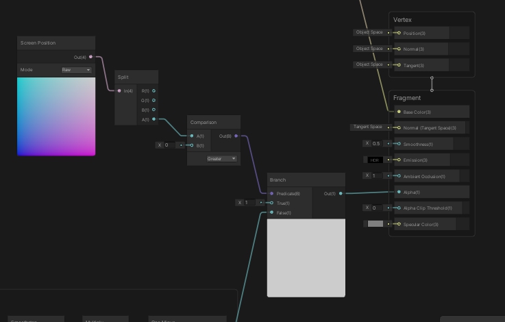
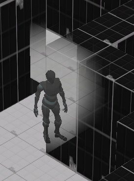
I want my shader to only be applied to the walls in front of the player and ignore the ones behind him
https://cdn.discordapp.com/attachments/885794879345680424/897835907930017792/InkedGB3Aekv_LI.jpg

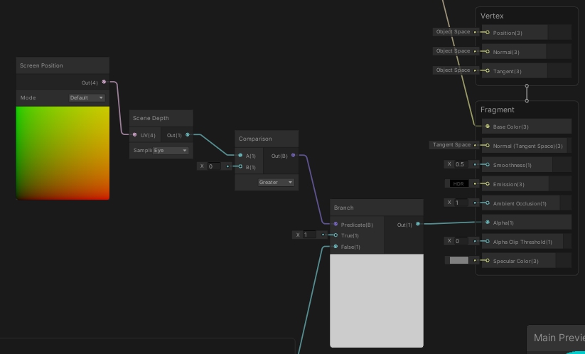
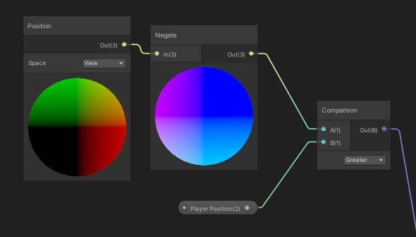
I'm assuming I have to get the depth of the wall and the depth of the player to compare them and see if the wall is behind the player.
First of all I'm not sure which of these two methods is the correct one to get the depth of the wall or if both output the same result
https://i.imgur.com/B51uRJu.jpg https://i.imgur.com/Dt31ZTZ.jpg
Second, I have no idea how to get the depth of the player to compare it
Right now I have a property for the player position which I assign in a script like this
https://i.imgur.com/HfGja4F.jpg
https://i.imgur.com/CE89W2s.jpg
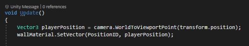
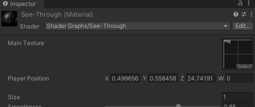
And I'm assuming the Z value is the depth, but I'm not sure how to get that value so I can compare it to the depth of the walls
In he shader, you should use the "position" node, in "view space". Maybe you'll have to negate the Z axis (I'm never sure in what direction it's going), and you'll be able to compare it with the Z value of your player position (that is also in view space)
Hi, thanks for your response, do you mean something like this?
https://i.imgur.com/SNpuMPZ.jpg
This is the result i'm getting right now https://i.imgur.com/mWc01YH.jpg
it's a bit off but i think it's towards the right direction
It's not easy to see how the branch is working here.
May I recommand to switch your shader to a more "debug" setting :
full opaque alpha, and output 0 or 1 one the albedo from the branch, so you can directly visualize what is happening for this specific node
Alright thanks, I’ll try to do that later when I can
How does Unity calculate shadows in URP? And what does Normal Bias mean? Do i need to put normal's maps to each individual material to calculate it more accurately or is it something built-in?
From my understanding Normals here mean faces or vertex normals. Nothing to do with normal maps. Normal bias is supposed to reduce shadow artefacts(surfaces shadowing themselves):
https://docs.unity3d.com/ScriptReference/Light-shadowNormalBias.html
The shadow calculation is probably the same as in built in: a depth texture is rendered from the perspective of the light and used later when rendering the actual objects to attenuate their color.
in this case Normal is referring to the mesh normal, this is the data that says how a face on a mesh is rendered, directional information. its what lets you set a mesh to be smooth shaded for example. so not quite the same as normal maps, but they are related.
@kind juniper @stark vessel Thank you very much! Setting normal bias to value of 1 kinda makes the shadows look like noodle, they slim down for some reason. If i set it to "0" i get those artifacts you mentioned. Its like double edged sword. Any value between 0 and 1 makes shadows either noodlly or makes texture artifacts depending on the value.
anyone know if you can get better noise nodes for unity? ones with more options like the blender noise nodes have. the ones in unity are so painfully limited... maybe someone who knows more about math and there use in this stuff can stack a bunch of math nodes to make them as good but that is a real pain and outside my skills
If you own substance designer you can export noises directly as png and since it lets you manipulate noises, you can get all kind of variations and create your own.
I need noise generated in unity
sadly to my knowledge they are pretty limited in unity, maybe there are some in marketplace? You can also try to export noises from blender, create a variation you want and export it as an image file?
exporting noise textures is easy, but for some thing you need to generate them in the shader to get what you want, very important if they need to be animated
@stark vessel are you trying to create something procedural?
yes
I see, yea you might wanna look into the theory behind noises to create your own, but i dont think shader editor will cut it. You might need to code one from scratch. This might help : https://www.youtube.com/watch?v=wbpMiKiSKm8&list=PLFt_AvWsXl0eBW2EiBtl_sxmDtSgZBxB3&index=1

Welcome to this series on procedural landmass generation. In this introduction we talk a bit about noise, and how we can layer it to achieve more natural looking terrain.
A quick summary:
'Octaves' refer to the individual layers of noise.
'Lacunarity' controls the increase in frequency of each octave.
'Persistence' controls the decrease in ampl...
but since you're trying to create your own, i suppose you've already heard of this guy.
I dont have the skills to make my own, that is why I was asking if there were some improved noise packs or something out there that add better noise nodes. I have a few, some simplex noise nodes but they dont have the extra options I am looking for. really need some 3d and 4d noise
not for anything specific at the moment, just trying to expand my toolbox
@stark vessel Got it, there might be some in the marketplace maybe. I've heard Amplify shader editor has some unique features but i never used it before, its also a bit pricey for me.
if i have a shader that been made for Stander RP and it doesnt support URP, is there is a way to cover it to URP or do i have to make the shader from scratch ?
Hi i want to create custom node that allow me to use different values per different passes, in this case I want to have different alpha for shadow caster. This is what I've did but it don't work (It looks like it always execute Out=ShadowVal; ) I'm stuck and I don't have any idea how to solve it 😭

If you're in URP and SG v10+, try this (with 0 and 1 replaced with your inputs). If you're in HDRP I think this also works, just don't use the include.
#ifdef SHADERGRAPH_PREVIEW
    Out = 1;
#else
    // For URP this is needed :
    #include "Packages/com.unity.render-pipelines.universal/Editor/ShaderGraph/Includes/ShaderPass.hlsl"

    // Test if we are in the SHADOWCASTER pass
    #if (SHADERPASS == SHADERPASS_SHADOWCASTER)
        Out = 1;
    #else
        Out = 0;
    #endif
#endif
You have to recreate the shader, likely easiest using Shader Graph.
Hello fellow unity-ers!
I have come to you today with a shader error i can't find anywhere else: I am using an unlit shader graph and trying to emulate a cel shaded look, which is all going great- the problem is getting the unlit shader graph to recieve shadows. I have tried two different tutorials and the end result is the same: large bands of shadow running across the object's mesh.

the bands get wider and thinner when the camera rotates. They only appear once I use the debug inspector to add the keywords _MAIN_LIGHTS_CALCULATE_SHADOWS _MAIN_LIGHT_SHADOWS_CASCADE and _SOFT_SHADOWS.
Any help at all would be greatly appreciated- i've been scouring the forums for weeks and can't find anything that sounds close to this. The shadergraph has defeated me soundly.
Is there a maximum number of colors in a gradient?
I'm passing custom data throw the particle system to a custom shader, the problem is I can no longer use a texture cause the UV is occupied with the custom data, any solution?
Oh I found a solution nvm, you need to add a UV on the custom vertex streams , so the texture receives the UV and maps it back, makes sense I guess
8 I believe
is it possible to get the color of a texture for the screen pixel to the left of the current value
or even just like, how many screen pixels a texel takes
basically just need some way to get the relationship between texture size and how many screen pixels it takes up
Yes you can, if your mesh was vertex painted
e.g: a cube with left and right sides were painted with blue, and you want to change the top which was painted green, then split the vertex colors get then combined the colors you want which in this example is green
the shader is for a sprite, not a 3D object
Sorry, only know how to do it in 3d 🥲
ill try to tackle the main issue then
I have a shader that creates an outline around a sprite but the outline is never even

some parts of the outline are thicker than others
I'm (very slowly) building a node library to add more nodes to shadergraph. Including more noises.
You can get it here : https://github.com/RemyUnity/sg-node-library/tree/doc/rush
https://github.com/RemyUnity/sg-node-library/blob/doc/rush/Documentation~/nodes/noise/noises.png
Still, there is no perlin/fractal noise there, as it can be very costly, you'll have to stack yourself multiple noise octaves to do it.
thought this would be it but it just always uses the screen size

I have some custom lighting functions & SubGraphs here which you could try. (Also won't need to enable any keywords in debug inspector with this) https://github.com/Cyanilux/URP_ShaderGraphCustomLighting
question, i have this shader file for SRP but i want to convert it to URP, is there is an easy way to convert it since i have 0 idea about shaders ?

Well, any noise can be costly, what I tried to say is that if you use fractal noise, the cost will raise with the number of octaves, as you will be doing one more noise calculation per octave.
You probably meant "I have this for the built-in renderer".
There is no easy way to convert it, no, you'll have better chance to find an equivalent that is already compatible with URP
Oh man, you're that guy that wrote a guide about converting shaders to URP! Didn't realize you were a member here. That guide was very helpful! Thanks a lot! I was the one who asked about vertex IDs and on GitHub if you remember.😅
Hey guys, I'm trying to procedurally generate some bumps with a shader graph but for some reason on my custom models the normal is incorrectly applied.
This corner is a single model, as you can see on the left the bump is correctly applied, on the right it's stretched.

As I posted this I realized my rooms aren't UV unwrapped yet as it was just a test, that might be it
That did not fix the problem, so any ideas are welcome
are you using a triplanar shader or a UV based one?
I made my own, still new to the shader graph so I might have missed a step, this is my setup, I build a normal from generated noise and apply it to the tangent normals input

Ah my bad, it actually fixed it, I had to manually reimport the asset but now it seems to look ok
😉
Now off to figure out why i'm getting blocky lights even tough texel view shows all green

that's either a lightmap texture wrapping error or you need to increase padding
mipmapped textures can get that look
Hi, when writing fragment shaders for use in URP - specifically on the Oculus Quest - is there something I should be including in my code to make them fully work?
I've written a simple shader that divides up a quad's UVs and draws a randomly sized rectangle in each square - I'm also making the rectangles grow and shrink over time, using a sin function..
However on building my apk file, I'm finding the random part or the growing parts of my code are not working at all - and I just get yellow squares of the same size, instead of like the ones shown in the image.
So far, I've tried building it using GLES3 and Vulkan -both give me this result. Using the Built In Renderer seems to be fine though.
I might post this in the VR section too..hope that's ok.

Hello unity ppl! I am trying to make a no-texture effect like Saturn (or stratum) for a trilinear side-of-a-cliff and I can't figure out how to add some waves so it's not just parallel lines. I will multiply the result with a Gradient for colors. Please help!

blend it with some more noise, like the pokadot one I cant remember the name of. maybe distort the mapping with that
Hey, I'm trying to make a pixel art animation, but in 3d. I originally wrote a c# script that just changes the material main texture every given amount of seconds, but i'm worried about the performance. It was suggested that I do a texture offset with a sprite sheet instead, which sounds like a good idea, and I could easily write that in a surface shader. The problem is, in the shader I want to have clipping functionalities and still have proper shadows/all the lighting stuff and whatnot, but I really don't want to spend time writing that. Has anybody dealt with something like this before? And if you have would you mind telling me what you did?
Thank you so much!!!! That shadow subgraph was exactly the fix i was looking for for so long!!!!!!
anybody here ever made a shadergraph that affects unity world space ui text inside of HDRP?
Hey, Do you have an idea to implement this shader?
Is it a texture sheet? fireworks
What about this awesome fantastic skin
This one is probably a texture sheet.
The other one probably has some procedural animation.
Or could be a texture sheet as well. Just sampled with screen space.🤔
hey guys are block nodes not available in 2021.1 URP shadergraphs
How would I render a particle effect trail onto shader graph material.
I’m following the reactive water tutorial by minionsart but I used a shadergraph water instead of the coded shader that they used
I’m trying to get a toony ripple effect when a collider is moving through the water
anyone know a way I could convert the color output of a Black Body node into an HDR color with adjustable intensity in URP? in HDRP I would just plug it into an Emission node.
thanks, yes it is in screen space. I want it :/
Can I find something like it in shadertoy?
I need some keywords
i really dont understand, what am i doing wrong?

Does anyone know of any tutorials or methods to achieve a retro fade in / fade out effect in Unity? Here's an example of what I'm talking about.
Not sure if there's a screen shader that would round color values to a restricted palette or if that would even be a good approach. but wanted to see what existing knowledge was out there.

I created this video with the YouTube Video Editor (http://www.youtube.com/editor)
I've also seen some articles in other systems (PICO-8 for example) that explains part of the process but am not sure the best way to translate this to Unity shaders
Does anyone know if it's possible to draw directly on top of another pass? I figured out how to do them separated, but I'm struggling in combining them

are you trying to do decals?
kind of
I'm doing something along the lines of splatoon ink system
Using mix and jam repo as the baseline
And I want to add that on top of a toon shader I'm using
Tbh I could probably brute force it, and just create a duplicate of the toon shader, and just mash the ink code in there
I did that, it's an ugly solution, but it works :P

i have a dissolve effect but i want the output to only increase and not decrease

The Fresnel effect adds an outline to spherical objects, but what I wonder if there's any way to add a fresnellike effect but to cubes?
Hmmm. I wonder if some sort of internal-outline will work for you. But I'm not sure how to make that a gradient.
You could look into barycentric coordinates (google it) and maybe use vertex colors to determine how close you are to edges?????
Alternatively, use a texture to "map" it onto the cube...kind of like a mask that is a gradient. That might be the easiest way.
BTW Fresnel is an internal outline too. Unless you're using some more sophisticated external outline technique.
im tiling this texture in screenspace and find that it often has pixels falling on the wrong coords. any idea why?

Hey guys, I'm wondering if someone would be able to help me get the hauntedpsx render pipeline working.
I have followed the instructions, but for some reason I am getting a compile error that says "Assembly with name 'com.hauntedpsx.render-pipelines.psx.Runtime' already exists (Assets/Shaders/com.hauntedpsx.render-pipelines.psx/Runtime/com.hauntedpsx.render-pipelines.psx.Runtime.asmdef)"
I tried deleting the folder that that message points to, it was automatically put back, but now it seems I am able to run my project
yea im completely unable to get pixel perfect screen coords 
randomly changes from 16 pixels to 17

Welp, I am gonna need some help fixing this

share your graph
You mean the stretched areas?
ive got it sorted. for some reason the uv coords werent playing nice with the same math ive done in other programs.
Oh, NVM, I fixed it, just had to restore a backup
Hey all, i dont have photoshop is there any other way some online tool to make a mask map ?
Hey, anyone know how to grab a cubemap of the surrounding area and distort that? I need to create distortion but I can't use grabpass.
An open source alternative to Photoshop is Gimp.
Don't know about any online tools but might find something if you google a bit.
Thank you
I use Paint.NET for a lot of simple things.
Or GIMP for more complex stuff (rare for me now).
reflection probe
And how do I apply that to a distortion shader?
https://www.youtube.com/watch?v=C5YfSmSLZHI like this, only add in some noise

This is a tutorial on creating a simple refractive glass shader using the new API for custom nodes in Shader Graph v6+.
To learn how to add normal mapping and other cool looking additions checkout my other tutorial:
https://www.youtube.com/watch?v=-7UmfKUb1Zg
Checkout my assets for more Tuts!
--------------------------------------------------...
I dont know the details yet, its something I am also working on
I currently use scene color but I am hoping maybe the reflection probe method will let it work with transparent mats, but dont know for sure
What pipeline?
If URP/HDRP...you can't use grabpass the old way. So you use the cube map from a reflection probe, like @stark vesselsaid...OR...if you only need the background you can use the scene color node in SG, but do your distortion in the transparent queue.
Distortions are accomplished by mathematically screwing with the UV that you're sampling with to distort the sample...either from the probe or from the scene color locations.
Hello
Can you help me
To write 2 subprograms in 1 shader
?
Subgraphs?
Write each subgraph by itself.
Then use a 3rd (main) shader and include both subgraphs. 🙂
are uv coordinates similar to SVD linear algebra? Singular Value Decomposition?
Nope not shader graph
Shaders writing
How can I change a value from 0 to 1 over time? and reset it when a boolean is true for instance
in shader graph
hey so i want to add in psx shader to the camera but idk how to do that
Just call them as subroutines.
I don't understand your question.
Shaders support functions that you can write and call, just like C/C# does, but with a few more restrictions.
You don't. You do that in C#, since C# will retain variable values between frames. What you pass to the shader graph shader is....the result. The frame's current setting of "t".
"t" would be your value between 0 and 1.
is there a guide to shaders? i can't even find docs on stuff like cull zwrite and ztest
Also i got this but I still don't have my .shader files formatting properly...
https://github.com/tgjones/HlslTools
like when adding a new line to Properties the formatting isn't in line
Is it more efficient to sample from a noise texture or create it? for example perlin, voronoi and simple noise
Generally, sample from a texture or some calculations like pow, dot, sin/cos and some math calculations
Yeah, you can use Time node to get smooth interpolation in shaders but theres no any good ways to make that reset stuff working
Havent profiled that myself but Id imagine using texture is much much faster (since all those noise functions uses very fancy math such multiple sines and pows)
So for constant values, textures are better
What about gradient?
some pow, lerp and multiplication or gradient texture
I dont know if source code for those exists somewhere but you can see one outcome for those functions from manual if you want to see what they really do


horizontal scrolling, Are they in local space or use an extra uv? I think local pos
Not sure but it seems it can use same uv for that and for texture
Id not use texture because its not so much calculations to do it procedurally and the texture is much harder to change when you want to trim some values. Usually you dont need to care about optimization before you get performance issues. When your shader is ready you can try to improve the performance if you need to (trust me GPUs are veeery fast nowadays). Imo its much easier to change afterwards since you know exactly what type of procedural texture patterns/ gradients etc. you need.
It is awful, maybe because bad texture no seamless,etc.
It is mine. I want something like Rec16. It is simple scrolling + distoration texture. :/
The space is local in this video
I'm trying to write my own shader for sprite animations, but to do that I need to have proper shadows. The dog is my own custom shader, and the other objects use unity's standard clip shader. I'm not really sure how to get proper shadows... I'm just using a surface shader btw.
{
    Properties
    {
        _Color ("Color", Color) = (1,1,1,1)
        _MainTex ("Albedo (RGB)", 2D) = "white" {}
        _Glossiness ("Smoothness", Range(0,1)) = 0.5
        _Metallic ("Metallic", Range(0,1)) = 0.0
    }
    SubShader
    {
        Tags { "RenderType"="Transparent" "Queue"="Transparent"}
        Blend SrcAlpha OneMinusSrcAlpha
        LOD 200

        CGPROGRAM
        // Physically based Standard lighting model, and enable shadows on all light types
        #pragma surface surf Standard fullforwardshadows

        // Use shader model 3.0 target, to get nicer looking lighting
        #pragma target 3.0

        sampler2D _MainTex;

        struct Input
        {
            float2 uv_MainTex;
        };

        half _Glossiness;
        half _Metallic;
        fixed4 _Color;

        void surf (Input IN, inout SurfaceOutputStandard o)
        {
            fixed4 c = tex2D (_MainTex, IN.uv_MainTex) * _Color;
            clip(c.a - 1);
            o.Albedo = c.rgb;
            o.Metallic = _Metallic;
            o.Smoothness = _Glossiness;
            o.Alpha = c.a;
        }
        ENDCG
    }
    FallBack "Diffuse"
}

so i've been hesitant on upgrading my unity to the latest version cause i was trying to make sure i learn shaderlab instead of relying on shadergraph
if i update, can i not write stuff the same with shaderlab? and that stuff wont show up in shadergraph?
I don't think updating would change anything. Unless you're updating from built-in to URP. Also it's probably mostly CG/HLSL that you want to learn. Shaderlab is just the wrapper for the shader that makes it work properly with unity and expose properties in the inspector and stuff. Which you'll need to learn to, but it's not a big deal compared to actual shader programming.
ok
Generally speaking, math is faster than a texture lookup.
Think of it in terms of cycles....a texture read can cost you 100's (maybe as much as 900 on some systems) of cycles.
So that's a lot of leeway for math to come in. But math can be expensive too. And it all depends on the EXACT math being done, often in a loop with several octaves of noise.
Add to that the fact that the way GPU's work is that they hand-off the texture read/process to memory controllers and samplers, pause the current threads, and go off and start ANOTHER THREAD GROUP. This is latency hiding, and it is designed to let those 100's of cores keep busy. Of course, reading a texture causes external (from the core's perspective) memory access, which is slow by comparison to its local memory.
So that long texture read might not be as long as you think. 😉
In the end, the math doesn't pause, it calcs. So it won't go off and create another group.
You have to benchmark it all for exactly what you're doing. And the results can vary depending on GPU...for example mobile GPU's have to access system memory for texture reads, while desktop GPU's have on-board memory.
Remember that GPU's are built to use textures, and have dedicated hardware and methods of hiding latency for texture reads. But you can only do so much. Access is access. And long calcs with costly functions in loops take time too. All you can do is benchmark it for your use-case.
My best understanding ATM.
It's because you're using alpha clipping. You got a shadow, but it is a big "square" block because it isn't clipping pixels.
Research "Unity shader shadow caster pass".
And "Surface shaders alpha clip shadows" or something similar.
Perfect, When you say local memory, you mean cache memory/registers instead of VRAM?
So generally sampling from a texture is more expensive unless we have expensive calculations with multi octave layers and loops for example
Yep 🙂 BTW, cores actually have some of their own memory, and there's group-memory. But that's all too specific for this generalization.
Yes, we have shared memory for CPU and GPU in mobile devices
For textures, can they be stored in cache memory if they are small?
#archived-shaders message
and can you see this shader please?
Is it better to have it in local space or uv?
I want it to use this effect in different weapons
My shader is in local space and simple scrolling
Sure, that's what a cache does...caches memory accesses. So if happens to be in cache-memory, it's in cache. It's auto-magic, like L1 or L2 cache on the CPU.
But there's something we programmers do with "shared group memory" and you can research it, but may not need it in this case.
I'm running off to work right now....have a good day. 🙂
Left: Standard shader. Right: custom vert/frag shader outputting UNITY_BRDF_PBS. One directional light, no skybox or reflection/light probes. What causes the big difference here? Is there another macro to be used instead?

I don't really know about the main issues but these lines can be fixed by normalizing the normal vector on top of the fragment shader. By default normals are bit different length because of how interpolation between fragments work

this may help understanding the problem in interpolation between vertex and fragment shader (orange arrows are normals saved per vertex, red ones are normals on fragment shader)

It is based on vertex (right side). To interpolate between normal vectors, you need to figure it out in fragment as well, also normalize them
//frag
float3 worldNormal=normalize(i.worldNormal)
Nice illustration 🙂
thanks
Alright, the normalize fixed the interpolation issue, thanks!
That still leaves the very big difference in color and specular highlight though

Maybe some gamma/linear conversion is needed ?
Ooh, got it - the light was set at intensity 2, and my custom shader didn't take that into account. Just multiplying the light's color by that factor fixes it. 🙌🏻
Hi! I have been checking around how to make a 2d sprite renderer cast shadows with URP... nothing worked for me. Currently using URP/SimpleLit shader and tried Shadow Caster 2D script as well...do you guys know how to do it right?
finally found that going to debug mode in inspector + activating "Cast Shadows" was what I was missing...
Standard shader is different from custom fragment/vertex shader :/
Different lighting
It may be hard to get exactly same results but ig it doesn't do anything very fancy tho (just blinn phong etc.). Standard shader doesn't really mean much, it's just fragment/vertex shader that uses unity's lighting stuffs
It matches perfectly now using the PBS macro 👌🏻
And luckily it's still a lot cheaper than the standard shader, the Quest 2 really cannot handle the standard shader
does that receive or cast shadows?
Well not by itself obviously
But I don't need shadows so I'm not going to add that in
Hello,
I'm trying to get the spot light in Unity to have no fall-off. I want it to illuminate objects the same amount no matter the distance. Realtime light.
As far as I understand, I need to write a custom shader for that?
you're right that's not possible without custom shader
you can google for spotlight shaders
and i'll probably play around with the attenuation function in the shader i assume?
or the calculation rather
wait, have you tried to crank up the range of spotlight to something incredible large?
that may do the trick
i did @dim yoke and i tried to dynamically set the intensity because i need lots of intensity for objects 5+ units away. but since the spotlight has a radius, and a closer object happens to be in the radius when i'm looking at a distant object, the closer object becomes super bright
it works if every object in the light's radius is relatively the same distance, but if a close object comes into the "beam" then it's very ugly
it seems like hdrp actually have way to do that but that won't work in other render pipelines afaik: https://forum.unity.com/threads/changing-the-falloff-of-a-spotlight.1113265/
this might work, i'll try to play around with it. i'm in URP right now but will attempt a switch, thanks @dim yoke
Hi, i'm making a shader that outlines an object. Thing is, i don't just want to outline the border of the object... Neither do i want to outline each triangle... I want to outline all flat surfaces in the model.
That is, given something like a cube i'd highlight the 12 edges(excluding the ones hidden behind the cube), rather than it's border or triangles.
I've seen some ways of doing similar things but the ones I've seen rely on color or depth in a fullscreen effect and seem to have widely inconsistent line thickness depending on camera angle and distance.
For reference, i'm trying to achieve something similar to the scanner effect from Hardspace: Shipbreaker (see picture)
If you know of a shader or any other technique for that matter that can outline as described feel free to @ me. Thanks!

any tips or ideas are welcome 🙂
@wicked stream you could draw a texture mask with all outlines drawn in?
wow... it was legit one line I had to add in the pragma. Thanks!
You mean to simply paint the lines on a texture? I feel i’d be hard to have the line width stay constant between objects. Seeing how the line would be painted on to the surface of the object i’d also mean the line would look alot thicker if you where looking at an edge diagonaly as opposed to straight on from one of the faces makeing up the line. I feel i’d come out looking more like paint than a true line on the edge
I will, i merely doubt the effects believability if you will 😉. I’ll tell you how it went when i’ve tried. If you’ve got more ideas in the meantime, feel free to say so 🙂
Hi all, i need a shader that is affected by light but also supports transparent tiles, i tried the one here but all the transparent tiles are still black even though it's approved as working
Unity is the ultimate game development platform. Use Unity to build high-quality 3D and 2D games, deploy them across mobile, desktop, VR/AR, consoles or the Web, and connect with loyal and enthusiastic players and customers.
i tried moving the alpha bar, it doesn't do anything
Wouldn't the default sprite lit shader with URP work?
can you be specific which one? i couldn't find one that works
Create -> Shader Graph -> URP -> Sprite Lit Shader Graph
Or you can just try using the "sprite lit default" material
hmm, the sprite/diffuse actually worked, thank you
I think doing it specifically for quads and not triangles makes it much harder! Depending on what modelling program you are using, you might be able to automatically generate coordinates for a second UV channel for your meshes (so you at least do not have to manually modify all textures). Another approach, depending on your modelling program, is to include something like a unique ID for each face in one of the channels (eg, that second UV, or vertex color) so that you can then distinguish between these in a post-process effect to make crisp 1px lines
I'm sure there's a better way of doing, can't wait to see what someone else suggests 🙂
You MIGHT want to experiment with surface normals and the ddy/ddx funcitons to tell you when you reach an edge.
But the outlines produced that way may not look that great.
Otherwise, building it in like Beatrate mentioned is not bad at all.
There are several other techniques that I don't even remember off the top of my head. It's all a PITA though.
i've already researched a little surrounding doing it with the normals approach but with no great results. i'll look into all to the suggestions 🙂
Why is this grass shader that ugly? what did i do wrong/whats missing?

Like addshadow? I couldn't remember off the top of my head this morning. lol
BTW, here's an old link that discusses this:
https://forum.unity.com/threads/clip-in-surface-shader-doesnt-clip-ligthing.470284/

Unity Forum
I'm trying to make a simple cutout surface shader in forward rendering (VR) and even tho the pixels are clipping properly, I am left with a shadow...
yep that's the one
I keep trying to make CommandBuffer.DrawMesh work with a custom depth target but it doesn't work 🥲
Fuck URP, mang.
I crawled all over its source code.
Copied the code from ForwardRenderer and DepthOnlyPass..
And it doesn't work at all.
The depth target is always black.
what are you trying so far? (also, the render-pipelines channel might be a good place)
eg buffer.SetRenderTarget(yourTarget), ... context.DrawRenderers(renderingData.cullResults, ...)
Well, setting render targets in the renderer features is not recommended.
I do this cs public override void OnCameraSetup(CommandBuffer cmd, ref RenderingData renderingData) { cmd.GetTemporaryRT(skyFogDepth.id, descriptor, FilterMode.Point); ConfigureTarget(skyFogDepth.Identifier()); ConfigureClear(ClearFlag.All, Color.black); }
To set the target up.
And in the execute is just this: ```cs
public override void Execute(ScriptableRenderContext context, ref RenderingData renderingData)
{
CommandBuffer commandBuffer = CommandBufferPool.Get(ProfilerTag);
            WaterRenderer water = WaterRenderer.Instance;
            if(water != null && WaterPrepassMaterial != null)
            {
                water.Render(commandBuffer, renderingData.cameraData.camera, WaterPrepassMaterial, 0);
            }
            else
            {
                Debug.LogWarning("Water missing");
            }

            if(TestBloop.Instance != null)
            {
                var b = TestBloop.Instance;
                if(b.Renderer != null)
                {
                    commandBuffer.DrawRenderer(b.Renderer, WaterPrepassMaterial, 0, 0);
                }
            }

            //commandBuffer.SetGlobalTexture(skyFogDepth.id, skyFogDepth.Identifier());

            context.ExecuteCommandBuffer(commandBuffer);

            CommandBufferPool.Release(commandBuffer);
        }```
Which basically resolves to cmd.DrawMesh in water's case.
And bloop is just a test script for testing if DrawRenderer is also borked in this case 😄
So like I tried all combinations of ConfigureTarget.
Specifying only the color attachment, specifying both color and depth attachment as SkyFogDepth, setting the color attachment to BuiltinRenderTextureType.None and the depth attachment to SkyFogDepth...
Nothing works, it's always black.
What does RenderDoc tell you about how it's rendered? Something will be missing. Either the depth buffer isn't bound or something in the draw call causes it to not write.
just to check - your water shader is custom?
And I have to ask since this has tripped me a lot in the past: are you sure it's not just very dark? Sometimes you have to remap to see anything in a depth buffer.
(also depends on if you are ortho or perspective for the above)
Holy shit, it is

😅
😄
I have a Texture2D of 16x16 pixels holding data for this 16x16 tiles gridmap (a mesh of 8x8 chunks), data held in RGBA format. the A channel (rgbA) holds terraintypeID data, an integer that should change the texture of the tiles to the appropriate texture (in a Texture2DArray).
But I don't know how to read this 16x16 texture data, and use the data for setting the texture in those cells. The only object that so far has managed to change tiles' texture, is the UV map, in which the first (from bottom left) tiles change to respecively 0th, 1st, 2nd, etc. texture in the array, but I just cant seem to get this 16x16 texture2d to do the job.... Any ideas? I have been messing with it for many hours and I'm close to giving up..

Current attempt, where HexCellData is that 16x16 texture2d..

Are you using an integer texture format for the HexCellData texture?
It's created in Unity:
cellTextureData[cell.Index].a = (byte)cell.TerrainTypeIndex;
here the .a value is filled with the index
You mean it's created by an internal Unity system? The built-in tilemap?
cellTexture.SetPixels32(cellTextureData);
Here the color data is added to the texture
no, a custom 1, from the catlikecoding tutorial
And what texture format are you creating the texture with? Same as the tutorial?
Shader.SetGlobalTexture("_HexCellData", cellTexture);
Here its sent to the shader
None of this tells me the texture format.
By default, a texture can only store floats between 0 and 1
So trying to assign a int (or byte in your case) will just get clamped
is it filtermode?
No. I assume you're making a Texture2D instead of RenderTexture?
Texture2D cellTexture;
It's TextureFormat, which is passed in the constructor
https://docs.unity3d.com/ScriptReference/TextureFormat.html
TextureFormat.RGBA32
You need to multiply the alpha by 255 before you plug it into the Index of Sample Texture 2D Array
Because it's read as a float in the range of 0-1 in the shader.
Multiplying by 255 will bring it back to the byte range
is there a way i can read the value? Currently the whole map went to the highest level in the array turning it all into snow
Best you can do from a shader is output it as a color somehow
it didnt do much, the color range was not necessarily the issue (might be another), it's especially the scale of the data texture, and how to make the shadergraph relate a pixel to a cell. I'm not sure if that UV2 connection has any effect. But if I connect the UV2 to the index, it does show different textures per cell (using the UV index numbers I guess..)
hi, is it possible to make a UI blur shader for 2D Renderer as there's no way of adding Render Feature to it ?
Anyone knows how to make shader like this working for mobile on Build in render pipeline?

-Infernal- Trading card🎃
#pixelart #ドット絵 https://t.co/1Jl6Rtt4DP
Retweets
1187
Likes
7688
If i have an exposed color variable in a shader attached to a material, is there a way to reference/change that color by name in a script?
nevermind- i think i figured it out!
I have a scene with two cameras, a 3d one(the one the picture was taken with) and a 2d one that looks directly onto the from of the scene(in an orthographic view). The yellow plane can move back and forth intersecting with the other cubes in the scene(the green is the floor that doesn't matter). If the yellow plane is intersecting with an object in the scene(the purple, blue, red cubes) i want that intersection to be rendered to the 2d camera. I have no clue how this can be done, I am thinking that a shader can do this but im not really that good with shaders. it would be great if someone knows how to accomplish this.

I am having this error in my console, is it something i should care about?

I could be wrong but are you trying to reference _MainTex when it isnt a thing?
You could look into "Constructive solid geometry" or you could implement your own solution that checks for every edge in the intersecting mesh to determine where it hits the plane, and then generate your mesh from the result.
i will look into both those solutions. thanks heaps, you are the first person that has actually replied with anything on all the messages ive sent
you bet 🙂
A crude but simple approach would be to render the scene using a second camera, orthographic projection with very close near/far clip planes (make sure your materials are double sided). That will slice the geometry, you could use a post process to tidy it up, eg to add thicker lines. It won't be a perfectly thin slice though
This is either achieved with parallax math in the shader or with stencil masks.
https://www.ronja-tutorials.com/post/022-stencil-buffers/
https://halisavakis.com/my-take-on-shaders-parallax-effect-part-i/
Summary The depth buffer helps us compare depths of objects to ensure they occlude each other properly. But theres also a part of the stencil buffer reserved for “stencil operations”. This part of the depth buffer is commonly referred to as stencil buffer. Stencil buffers are mostly used to only render parts of objects while discarding others.
T...
It's most likely stencils, since it's easier to use 3D geometry inside the card. Parallax is just distorting a texture to make it look 3D.
how do you create a fragment node like this with emission, metallic smoothness map etc? When I make one all I get is base color

The shader for the yellow wall could "just" do an intersection calc...turn off depth clipping, and instead, check the scene depth and see if it is within tolerance of the yellow-plane's depth. Or rather, you'll have to have all shaders be "smart", I think, and "know" where that plane/quad is.
You could even use a stencil to "mark" where the yellow plane intersects. You may not even need a 2nd camera. You'd put the yellow plane in a higher queue to make sure everything else is drawn first.
The ortho camera may not intersect the same pixels as the 3d depth camera anyway. Maybe that's what you want? IDK.
Just some thoughts.
Or research "intersection shader".

Unity Forum
Hello,
Is it possible in current Shader Graph state to create a shader, that would highlight intersecting geometry?
To elaborate: the shader would go...
The blocks should change depending on the graph surface type specified in the Graph Settings tab of the Graph Inspector window (Lit for the ones you describe)
I need better precision for a shader effect, and tried to replace a custom node's Vector2 with Double2. Shadergraph then raise the following compilation error:
"ps_4_0 does not support doubles"
Yet my build platform is set as PC - how do I fix this?
it doesnt mean playstation, it means pixel shader
Hey hi! Anyone knows how can i modify a culling texture on runtime using a collider?
Im using a clipping shader but i dont know how to paint the texture when colliding with the object so the shader can dissolve that colliding part
@leaden zinc to modify a texture, you need to render into it.
Since you're using colliders and colliders are mathematical shapes, I think it would be best to create a shader that can output a collider's position, rotation and size on the UV of your model
Thank you for the help. Will try set that up.
Im using a Unity shader (Toon) and i dont know how much id be able to modify, but i'll see.
Well you need a wholly custom shader
Say you're using sphere colliders, since those are easiest
You give it inputs of a world position and world size
In your fragment shader, you calculate the distance from that fragment's world position to the sphere's world position
You can then use that distance to color everything within the sphere's radius white, and leave the rest (0,0,0,0)
Using Graphics.Blit() or similar, you render into a render texture that's used for the dissolve effect using blending, so you can add to it frame after frame
To use multiple colliders, use an array of positions and sizes instead
To use box or capsule colliders, you'll have to look up the math on how to define those
... isn't pixel shader 4 more than a decade old?
Anyway, is there a way to tell Shadergraph to not bother with compatibility toward older shader models?
Edit: Nevermind, apparently the good ol' "#pragma target" still work in custom node code.
@rigid terrace Thank you for the detailed steps.
I will try creating a custom one.
However i cannot leave the shader im using behind because it comes with very advanced features.
Wish i could make the dissolve shader calculations on top of the first shader result.
Thank you again 🙂
You're not leaving your current shader behind - you're making a new one solely for creating the dissolve map to feed your current shader.
Thats what i was lookin for.
Could you point out any source where i can learn more about this on detail? Or how should i look for it?
Using a shader to feed another one.
(Im already reading the book of shaders)
What it does is render a full screen quad using a given material to a given render texture
That's how you use a custom shader to render a particular thing to a particular texture
So in your case, you will creating a shader that outputs the position and size of (sphere) colliders in the UV map space of a mesh
Oh, about outputting UV map space - you will need to set the vertex shader to output the UV coordinates, rather than outputting the vertices in clip space
As such:
o.vertex.xy = (v.uv.xy * 2) - float2(1,0);
// Flip Y on DirectX.
#if UNITY_UV_STARTS_AT_TOP
o.vertex.y = 1 - o.vertex.y;
#endif
o.vertex.z = 0;
o.vertex.w = 1;
Oh actually, I'm messing up here - you obviously can't use Graphics.Blit, but instead need to render your mesh
I'd use a command buffer instead then
If you're on built-in - not sure if that exists in URP
Alright, so you want a command buffer: https://docs.unity3d.com/ScriptReference/Rendering.CommandBuffer.html
Where you first set the render target to the render texture you will use as the dissolve map
then you use commandbuffer.DrawMesh to draw the mesh of your model using the custom shader
If you're using a skeletal mesh, you'd need to bake it to a mesh first though 🤔
Im wondering, my custom shader is using shader graph, is there any node that works for this matter?
To output the position of a sphere? There might be
Got the dissolve working!

While I'm not sure what am looking at, I'm glad you got it working 💯
The problem with using the depth buffer for intersections is that it won't accurately capture intersections which occur behind other objects. Imagine looking at a teapot spout on, and making an intersection with the handle. The body of the kettle will fill the depth buffer and obliterate any information about the handle.
Yeah, that's the other part I mentioned...the "kettle" shader would have to be yellow-plane/quad aware as it is drawing. And do an intersection test. The link I provided did that with a sphere, but you could do it with a plane too.
Also, I think @regal stag had some examples of a plane "cutting" models, if you want to dig around.
Shader noob here. If I modify a shader on a game object, it seems like it modifies it for any component that uses that shader. If I want to modify this for .. one thing, then I need copy a shader and give that thing the new shader, right? I can't lean on Unity to handle that?
Specifically I want to have some outlines on some specific textmeshpro game objects - when I first modified the shader, it obviously changed every TMP .. in my entire game. I'm assuming I need to make a copy of the shader it uses, and modify that one to be my "outline" shader?
Let's figure out if you mean "shader" or "material" first.
I have a water shader that im trying to use a depth texture on to add foam, however the whole water changes color at once. I was attempting merge this tutorial https://roystan.net/articles/toon-water.html with my shader that had waves and lighting

Learn to write a toon style water shader for Unity engine, complete with waves and shoreline foam.
clearly the lighting has also dissapeared
this is what the original looked like

Anyone know why this is tinting the whole thing green? Shouldn't the multiply node only add green where the star is?

Well, you're adding green on top of the white background too, which doesn't automatically get clamped. You get a green that is so bright, it appears as white, but when it is darkened by the Multiply, it goes back to looking green.
So just adding a Saturate node in between the Add and Multiply node should fix this.
Oh wow, I didn't even realize there was some green in that white. That did the trick. Thank you!!
Hey guys, does anyone know how i could get all the light data coming from all the 2d affecting the sprite? Can i do it in shader graph or hlsl?
One of the things i'd like to do is make an outline of a sprite gradually more opaque the less light is hitting it
Any help is appreciated
I think the 2D lighting system makes a sort of fullscreen "lightmap" texture, so you would just have to figure out how to sample that texture in your sprite shader to see how much light is on each pixel of your sprite.
This is probably a good starting point, see how the default lit sprite shader handles lighting
https://github.com/Unity-Technologies/Graphics/blob/master/com.unity.render-pipelines.universal/Shaders/2D/Sprite-Lit-Default.shader
Hey guys, not sure if this is the right place for this.
I've imported a model and materials from blender - and they look great if I set the material to "opaque".
I want to set the material to "fade" so I can change the alpha of the material to make the player semi-transparent/etc.
Problem is when I set the material to fade - the geometry kinda "leaks" through the model - even at full alpha.
material rendering mode = fade:
