#archived-shaders
1 messages · Page 211 of 1
I'd contact the asset maker
(if you did 1 and 2)
or 3) make sure the prefab is using the URP materials
sometimes they have different prefabs for different render pipelines.
is it possible that i need to update URP from package manager
maybe
can't hurt really
but I doubt it frankly
unless you're on a really old version
Foliage still not working; i updated the material to URP
nvm i got it working!
Its using LWRP but no way to switch foliage to URP
Where would I go for Compute Shader Help (very specific question)? Is it here?
hey, i'm looking for a version of unity's standard shader that uses world space coords for texture tiling. I've only been able to find simple diffuse shaders that don't support normal or height maps
one way I can think right now is to change the particle shader render queue to be infront/after said gameobject shader queue
how do i know how high or low to set the render queue
https://www.youtube.com/watch?v=dsAg0UO5AH0
can anyone tell me why this guy is using a compute shader and not just the normal shader?
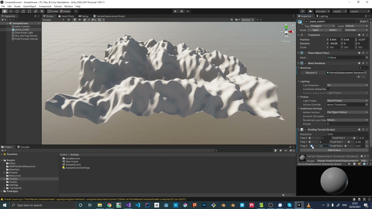
Small Perlin Noise implementation that can be used to create a wave like effect. It was part of a small project where I wanted to simulate erosion.
Simply put, it's a lot faster because it runs on the GPU.
A "normal" shader also does 🙂
It really depends on the need, but compute shaders can more easilly return data to the cpu if you want to, for example, do collision or move objects in addition to deform the mesh.
well after some further research it's not quite as simple, yes it runs on the GPU, but it looks like it completely runs on it. Like a normal shader won't draw it entirely on the gpu, it will still change the mesh on the CPU side so you can add mesh colliders etc but I'm fairly certain this does it allll on the GPU which is fast, but also means you can't do simple things such as adding a mesh collider
pretty sure anyways
No, a normal shader can change the mesh on the GPU, this is what the vertex shader stage is for.
A normal shader can also send back information to the CPU, but is not really meant to do that and it will be more efficient to do it in a compute.
A compute shader could also fully modify a mesh on the GPU, if you pass the data directly from the compute to the vertex/pixel shader.
But indeed, for physics, you'll have to read back the deformation to the CPU and update a mesh collider (which is very costly)
@swift yoke thanks for the link, haven’t watched the video yet. I was recently implementing a compute shader and directly modifying the vertex buffer and did not understand the difference between the vertex stage of a ‘regular’ shader… so as @amber saffron says the main advantage of compute compared to vertex shader is GPU-CPU communication?
Hi how would i be able to calculate the steepness of a certain triangle to be able to apply different colors?
@brisk chasm you can use a dot product between the normal vector of that triangle and a ‘reference vector’, probably ‘up’
thanks
@devout quarry the problem is that i only have the 3 positions of the verticies and therefore the normal could be in 2 directions. i dont know the direction of the normal
I believe the ‘winding direction’ of that triangle defines the normal vector by convention? Not sure what it is in Unity but (counter)clock-wise
Clockwise
On compute, it tends to be more useful for things which don't need a vert-frag pipeline. Just operating on data in parallel.
There is a lot of overlap between 'normal' shaders and compute shaders, but compute tends to make it easier to construct a pipeline of operations similar to the job system. Whereas a shader is really designed to transform vertices and figure out how to display texel information on them. You can use one to do the other's job, it's just going to be more annoying in some areas
But so still when using compute for something like ocean simulation, you’d do the displacement in compute shader and then still use a regular pixel shader for shading right?
Yeah. I've not personally used compute for that usecase though, so I can't really say why you would choose one over the other at the level I've done water surfaces in 😄
Yeah when looking for FFT ocean simulations online, they all use compute.. so there must be some benefit, while Gerstner waves are usually done in vertex stage of regular shader.. not sure why
I imagine it's to get straight to dealing with the data they need. Seeing as they need to generate all this varied buffer information, perhaps at different scales, it's easier to schedule a bunch of compute shaders to do the work vs trying to manage shaders to do the same thing.
On a lesser note, in this sort of space a lot of work is just based on previous work, so you see compute shader you do compute shader 🐒 😄
Exactly what I’m doing, I don’t know why but whenever I see projects online I always assume the authors know what they’re doing. Couldn’t hurt in this case, I love learning about compute shaders
Compute shaders are just a lot more flexible with the data they deal with and how big it is. I think that's the main reason it's used for stuff like this, though I can only speak from using them to make particle systems and do general data processing. Not from someone who's actually considered using them in a meaningful rendering pipeline
So, it seems that all my URP shaders are just... Broken on Android/Oculus Quest: https://cdn.discordapp.com/attachments/747004481799061524/862987048273444894/shaderissues.mp4
Anyone got any idea what the heck is going on here?
The outlines are missing, and the primary enemy shader has it's dissolve setting set to some arbitrary value
Does anyone have any tips about dithering a gradient? The dither node is quite basic and I'm not really sure how to use it.
I think you "basically" have to split your gradient into sections of two colors that you can dither.
So if you have 3 color keys in the gradient, you'll need two sections
Yeah in the end I used a Screen blend instead of just a lerp and now it looks natural. You just need to be aware it's going to be putting noise everywhere.
can anyone help me check where I did wrong? I already tried like few days...
            struct appdata {
                float4 vertex : POSITION;
                float3 normal : NORMAL;
                float3 tangent : TANGENT;
            };

            struct v2f {
                float4 vertex : SV_POSITION;
                float3 pos : TEXCOORD0;
                float3 normal : NORMAL;
                float3 tangent : TANGENT;
            };

            sampler2D _MainTex;
            float _TexScale;

            v2f vert(appdata v) {
                v2f o;
                o.vertex = UnityObjectToClipPos(v.vertex);
                o.pos = UnityObjectToViewPos(v.vertex);         //transform vertex into view space
                o.normal = mul(UNITY_MATRIX_IT_MV, v.normal);   //transform normal into view space
                o.tangent = mul(UNITY_MATRIX_IT_MV, v.tangent); //transform tangent into view space
                return o;
            }

            fixed4 frag(v2f i) : SV_Target {
                float3 normal = normalize(i.normal);    //get normal of fragment
                float3 tangent = normalize(i.tangent);  //get tangent
                float3 cameraDir = normalize(i.pos);    //get direction from camera to fragment, normalize(i.pos - float3(0, 0, 0))

                float3 offset = cameraDir + normal;     //calculate offset from two points on unit sphere, cameraDir - -normal

                float3x3 mat = float3x3(
                    tangent,
                    cross(normal, tangent),
                    normal
                );

                offset = mul(mat, offset);  //transform offset into tangent space

                float2 uv = offset.xy / _TexScale;              //sample and scale
                return tex2D(_MainTex, uv + float2(0.5, 0.5));  //shift sample to center of texture
            }```
Does anyone know of a way to get a texture to send to shaders to be able to differentiate between game objects when doing post processing.
You got it right until the left add node in your graph (corresponding to the float3 offset ... line, then you're doing something totally different. Why ?
Well, ok, it's supposely the same transformation, but it's done "by hand" in the code.
will it cause difference?
Not sure, but you could try.
use a matrix construction right?
yup
Note that on the position and normal vector node you don't have to add a transform node after, you could directly selecte the view space.
ok, thanks for the guide
Is it supposed to look somewhat like that ? https://i.gyazo.com/44889da967b8d95453c999d3075e9f81.gif


yeah it works after I form a matrix manually
Thank you so much 
Hum, yeah ... I don't really get why 🤔
I don't...either
could do that with raycasting and some ui world to screenpoint if you ever get stuck
But generally, im assuming the shader would be more optimized if programmed correctly
so im currently using instancing to draw many things, but I am wondering, if I have the thing in question, how do I transform it to rotate and stretch between 2 points that I have fed in in shader?
Might anyone understand why my shader is not displaying correctly? I tried altering many of the settings to see if i can get it to render into display preivew, but i have had no luck. I feel like there something basic I am missing, but am not knowledgeable enough with shaders to understand.

weird, that should work
are you using universal render pipeline?
and does it work in scene/game view?
yea, with a lit shader graph. I figured it might be just the preview, so i tried it in game, and it looks as the preview shows
to my knowledge, I am not sure how to check that. I downloaded Unities URP packack, and went to create > shader> Universal render pipeline > lit shader graph.
thats almost exactly what ive done this far, before this stopped me
I'm not completely sure. I did get it from the Package manager, (Universal RP).
oh okay so theres still more needed to do to fully set it up, right now youve only downloaded it

In this Unity game development tutorial we're going to look at how we can convert an existing project, using the built-in render pipeline, over to the newer Universal Render Pipeline.
URP is a Scriptable Render Pipeline that lets you create optimized graphics across a wide range of platforms.
It also allows us to create shaders and effects vi...
try this out
then you should be able to use shader graph without errors
I appreciate it
np
also keep in mind that shaders made for built in rp do not work for urp
and vice versa
so much to learn, shaders can be a bit intimidating
very but once you get a hang of it its really fun
I bet
what would be the best way to determin how much to scale an object by so that it stretches between two points in a shader?
Is the Lightweight Render Pipeline and the Universal Render Pipeline the same thing? Ive read sources making a distinciton between the, and those which say they are the same.
yep, lightweight is the older version of urp, they are the same
they renamed it
the difference is that lwrp is older, urp has newer features
So how can I represent the Gamma node From Blender in unitys Shader graph?

I'm having trouble implementing a Gaussian blur https://pastebin.com/Qh2pdnGY
Pastebin
Pastebin.com is the number one paste tool since 2002. Pastebin is a website where you can store text online for a set period of time.

Hi guys. There is no way to output to a custom SV_Target with Surface shaders, right?
I have heard rumors that URP will soon replace the built-in render pipline. Do you guys know if this is true?
Anyone got a double sided standard shader?
just make a new standard shader and set it to Cull Off
That works?
I think so
Hmmm
otherwise google will probably have more results than this channel
I mean, if you're gonna request a custom double sided shader you're gonna have to learn how to at least copy the code
I mean if I wanted to I could just packageanager
downloading a whole package for a double sided shader seems like overkill but you do you
Eventually that's absolutely the plan
But srp will be supported for quite some time
Ive got 2018.4.20f1, is there any free asset to make materials gradient?
is there a way to make a compute shader dispatch without pausing the cpu? Like a coroutine or something
oh it might be the GetData that slows it? Not sure
AsyncGPUReadback seems to be the way in case anyone wanted to know
why are not all properties from the vfx shader named correctly? and why is the material just a static image when its "animated" in the shader?

Is it possible to change the shader model on compute shaders? I get a warning that target is an unknown pragma
I need to change to sm4.0 becuase apparently you cant set array variables directly on earlier models because some older hardware doesnt support direct array indexing
There is a simple workaround but i'm jst wondering if i can jsut directly use 4.0
^the shader is animating with gametime from vfx and the properties are correct when adding "_" at the end. but why do i need to use the time node from the vfx?
For most cases you can use the Power math node
Because your program isn't executing. However, the VFX editor is animated its own time node.
Shader Code Flow Question: TMP_SDF.shader calls a function in TMPro.cginc, passing two variables as values to it, and. the function inside TMPPRO somehow uses a variable not passed to it that exists in TMP_SDF.shader ??? How is it that a function in TMPro.cginc is able to access a variable inside TMP_SDF.shader ???
TMP_SDF #includes TMPro.cginc, but TMPro.cginc does not include the TMP_SDF.shader... so I'm mentally missing how this is being made accessible to the TMPro.cginc function.
Hey, I've been trying to get rid of this "white haze" in my shader for quite some time now... Cant get it to work! 🙂
I know it must have to do with the alpha channel, and I've tried so much to sort it. Using Shader Graph

What am I missing? :/
Hello, any idea where could be problem of this jagged edges?

Usually jagged gradients imply you're running out of bit depth in the textures you're using
I believe that can also be an issue if your scene depth texture is stretched thin, likewise
Yeah I just dont understand why, its R24_Unorm, it should have quite enough data I believe
When I change sampler state to point I can see nice transition but then I see each pixel in point quality

What compression quality level is the texture?

Ah right, render texture
@merry rose Are the near and far clipping planes of your RT camera reasonably close to the terrain? That could significantly limit the depth texture's ability to store minute changes if they're too far apart
Still I'm not sure sure if the heightmap is the issue, the jaggies are kind of facing the camera so it could be something else too
jagges dont change when camera moves, they stay the same
and I am stealing heightmap from the terrain Data
also tried smoothstep but it came the same, so I am running out of ideas :/
I think you can get height information with an SG node, without relying on textures at all
If that's all you need
What rly?

You can control the start and end height using Remap's in Min and Max
I am doing that exact thing, just subtracting texture from object position data
What for?
here for getting the gradient from the height of the terrain upwards
Position already gets you a height gradient as it is
Am I misunderstanding
yes it does, I subtract with the heightmap and I get the gradient from terrain, not from mid point of the object
You can control the mid point using Remap's in Min and Max values
I don't understand why you need the crunchy heightmap from the terrain when you can get the same effect without it
but I am blending the object with the terrain

I need the gradient from the point of the terrain upwards on the object
so time is not the only limit to vfx shader. we also cant use position/uv nodes, but i can still use them. i now that i just can turn the particle to the right direction with vfxG, so i dont really need the vertex-position-output, but i still dont get it.
How is a cginc file aware of variables in a shader?
why is the tiling and ofset node not working with procedural nodes like rectangle (cannot use tiling)
Hi guys I am trying to use the URP SpeedTree shader, but I don't know how to make it show billboards ... as you see here, the "tree" just disappears at the point where the billboard is supposed to start

I guess Lit Particle shader works instead 🤷♂️
how do i change the alpha of a sample texture 2d?
shader graph? also what do you mean by change?
so use the alpha channel from a different image in place of an image's alpha
and again, is this shader graph?
yes
and this is what you mean?
no
use the rgba or rgb chanell from another texture to set the alpha of a different texture
the thing you said would work too though
yeah so all you have to do is get a combine node, pass the r g b values from the texture into the combine, and then the a from another texture into the a slot of the combine node
then there should be an RGBA output from that node
yeah thought of that doesn't work
oh what that should work..
what does it do instead?
in fact what exactly are you trying to do im still confused
it just has full alpha
trying to make a more realistic version of smoke, compared to this which i made earlier

I see that 2021.2 has Deferred rendering back again; since the deferred pass has a screen normals G-Buffer, I was wondering if that can be used for screen-space edge detection
also, DepthNormals was already available in the Forward renderer, does it have any difference?
are variables in shaders nullable?
I mean can I do something like have an array and only check it's content if it's not a null ptr?
yaaay i fixed it, thanks for trying to help @brittle owl , i had to add the textures instead of combining them.

when switching from unity 2020 to unity 2021 my grass and tree shaders (and some others) dont get dark at night anymore you can see them a shade darker at night but its a big difference anyone know why?
my grass is not dark at night. this is from 2019 https://gyazo.com/f5e4115b48f7a41ea4f048688e8dfa5f and this is 2021 https://gyazo.com/5442dce58826071e1f79da17da3e5282


Use the Comparison and Branch nodes
The "tiling" actually just scales the UVs (same as Multiply node). Textures can already tile because of their wrap mode. For procedural stuff that expect a 0-1 UV range use the Fraction node after the Tiling And Offset.
If I'm making a shader that uses ray tracing, do I create all the rays from script and pass them to the shader through a buffer, or would I somehow calculate the rays in the actual shader?
like what I'm doing now is creating a ray from every pixel on the screen and passing them all as a buffer of
struct Ray{
  float3 origin;
  float3 direction;
}
it just feels like this would be something you could calculate from the shader
is this URP?
thnks will try that!
unless you're doing raymarching, forget IFs in shaders
at the risk of sounding like an idiot - is IF an if statement? or acronym for something else?
then be helpful, and explain how to do the equivalent of branching without conditionals.
you could use equivalent mathematical operations, eg if your if is to return one of two values you can instead calculate a quantity which is 0 or 1 depending on the conditional and then do a x * a + (1-a) * y kind of thing
that's only got a vague chance of being understood by someone that already knows what you're talking about. Try explaining it in a manner appropriate to someone that actually needs to understand it, from a position of naivety. Otherwise you're talking to yourself.
I think the If in Amplify Shader Editor is an if statement yeah (oh wait, that screenshot is unreal engine materials - I think it is still an if statement though)
Just because an if / conditional is used, doesn't mean it's always going to branch though. Amplify also has an additional setting mentioned in the docs (https://wiki.amplify.pt/index.php?title=Unity_Products:Amplify_Shader_Editor/If) to toggle whether it actually produces a branch, which I'd assume is the same as the [flatten] vs [branch] in HLSL (see https://docs.microsoft.com/en-us/windows/win32/direct3dhlsl/dx-graphics-hlsl-if).
Can also use a ternary, which in HLSL doesn't branch, e.g. x >= y ? trueResult : falseResult, that's what the Shader Graph Comparison and Branch nodes use (in v10+ at least. It used to use lerp prior to that).
I think it's equivalent to what step() does too (but returning 1 or 0. But if you need other values it's better to just use a ternary as that would produce less operations than something like lerp(a,b,step(y,x)).
I'll be glad to explain further if the person I replied to asks me to do so, meanwhile your attitude won't lead you anywhere
it's you emitting a far stronger attitude. Narcissism driving it, perhaps.
this statement is incredibly bold, absolutely unreferenced and unfounded and so sweeping as to require something to back it up... like...WHY?
Why should it be forgotten in shaders? Why are conditionals available for all general shaders in an engine that barely suggests uses of raymarching, and why is raymarching an area in which conditionals are to be used? Your claims are ridiculous.
Why are you so aggressive?
Not aggressive, that's a judgemental call, and incorrect. Why are you making massive, sweeping, ridiculous bold claims that defy logic and common sense?
Why do you think it's better to disorientate a user unable to find a simple conditional in a shader graph that uses a different naming convention? Why do you dare think for this user rather than actually help them with an immediate and simple response.
You're not amazingly wise, even if you think you are. There's literally millions of reasons to use conditionals in shaders, and most of them aren't bad. Avoiding them is a later stage optimisation issue, that's far beyond being helped by your trite and ridiculously bold claim that conditionals should not be used in shaders.
<@&502884371011731486> I don't know what this person wants from me, but it's clearly harassment
If you say so. I think it's wrong to mislead users.
and doubly wrong to then make claims about my motivations for commenting on your misleading users.
You are clearly in an agitated state
another claim, also wrong.
Are the personal remarks necessary? Surely we can correct each other without causing a scene
If this user simply asked "why" instead of going through this tirade about us being unhelpful this issue would have been solved sooner, but it's clear from its first two replies that he really wasn't looking for an explanation as much as he was looking for a fight
another sweeping claim "looking for a fight"... that one might be projection.
Okay we get it, you're a badass. In the future, please don't tell people how they should assist others in this discord
Clearly it leads to nowhere productive and this channel is long since flooded with this back and forth.
In Shader type he has a legacy/particles and his main node only has color nad offset...

if i make it like this in shader graph is ok?

or i should change something else
It should be the same, does it work?
idk i dont want to make mess XD so thats why i ask..
offset means alfa here right?
Offset in the Amplify graph is the vertex offset
it's the same as that [Position] block in the vertex shader
Now, in that Amplify shader the alpha is passed as the Alpha channel of the Color port
that is, if you pass RGBA(0,0,0,1) in that Amplify Shader it will come out as black with no transparency
In Shadergraph instead, the [Base Color] port accepts only RGB, if you want to pass transparency you have to pass it through the Alpha Block
Ok i understand, thank you! I try make this slash i hope it works, so when he attach something to offset i should attach to Postion(3), right?
Is this projection, too?
!mute 588426769003053075 4d Stop spamming the channel, read the code of conduct in your time off.
 d3eds#9833 was muted
I have no time for people with such high IQ.
No, Position is used for some particular effects, like when you want to make a wobbly plane like an ocean
The shader only handles how you're going to paint the mesh, basically; if that mesh comes out from a particle system or a line renderer depends on how you want to make the effect
Ok thank you, do u know what node in shader graph is Append?

Combine
Combine, also Vector2/Vector3/Vector4
thanks!
Without wanting to throw oil on the fire, I'm still a bit curious about your statement on the if and branches @slow bear
Like, why is it so bad ?
Hi, how could one calculate spotlight falloff strength at specific distance when using HDRP? I need to calculate this on CPU.
I tried the following
float distanceNormalized = hitInfo.distance / _spotLight.range;
float falloffT = 1f / (distanceNormalized * distanceNormalized);
I think that should be half of the final solution. But it's not taking spotlight radius into account yet. No idea how to do that.
sorry again but.. how can i do something like that in shader graph?

agreed, this seems like pretty poor advice
as long as you understand alot of if's just result in both branches being executed and the unused one thrown away
and don't try to use ifs to save running calcs from a performance perspective
there's a ton of logic you just can't implement without them
Cyan pretty much summarized it.
BUT....it helps to understand WHY if's MAY be "bad" in shaders.
Basically, all conditionals are "ifs" when it is complied down to the machine level code...in other words, a calculation and a test of the result, with a branch for true/false. That's true for the ternary operator, or an actual "if" that you type out or whatever. If's are compiled just as ternary operators are compiled. And all conditional expression must get evaluated for any of them.
That said, what happens in a shader, with massively parallel cores, that all use the same program counter in a thread group? That's the thing...the cores work in lock-step with each other, "marching" through the code.
So if one core has to execute the "else" side of a conditional, and all the others execute the "if" side of it, they all step through BOTH sides of the code, and take up the time for both sides. If it's just a small expression that's only a few cycles, meh. But if there's a big block of true-code and a big block of else-code, you get a double whammy on ALL CORES regardless of the conditional.
Enter in Uniform values vs per-core values. So if you're branching on some uniform "global" value that's the same for all cores, say a setting you pass in on the material, it's no big deal. They should BRANCH around the other code assuming all cores don't need it. You may also need to use the [branch] attribute.
So small if's aren't that bad, and large blocks MIGHT be bad, depending on if it's a uniform (good) or usually-the-same-for-all type of conditional (good) or if there's huge blocks of code and a lot of variability in the conditional (bad).
All this has led to a lot of script-kiddie paranoia learned on reddit that "if's are bad in shaders" and that so overly simplified as to be nearly useless. Still, math is favored over conditionals if you can pull it off, like in the example above where you could multiply with 0's or 1's as conditionals in expressions.
My issue was resolved thanks
@meager pelican summarized it on point; I tend to suggest avoiding it because:
- it could be used carelessly by newcomers, especially when coming from CPU programming;
- because most of the times you need a
ifyou can replace it with a simple 0/1 multiplication or a lerp - because the user was asking for help on a shader graph, and I don't know if branch nodes are optimized or not.
Of course, if you're writing in HLSL and you know what you're doing there's nothing wrong.
It's always a bit tricky to understand it it's optimized or not, but SG will use a ternary expression to make the branch. From doc :
void Unity_Branch_float4(float Predicate, float4 True, float4 False, out float4 Out)
{
    Out = Predicate ? True : False;
}```

Depending on the context, you could also do a keyword branch ("better" for performance, but not for compilation time 😄 )Hey, I'm trying to make water foam based on the nearest surface of a plane mesh. In UE4, it's easy because there is a "Distance To Nearest Surface" node. I would like to achieve a similar result using shader graph (https://www.youtube.com/watch?v=QABi9T34b_k), but this is in UE4 😦

Patreon: https://www.patreon.com/StevesTutorials I made this video before making my new water material. Its still relevant because i still use distant fields in my new material :D
Twitch: https://www.twitch.tv/stevestutorials
Twitter: https://twitter.com/StevesTutorials
Discord: https://discord.gg/FDpvyKD
Unity doesn't have a node like this because the method used in Unreal to make this doesn't exist in Unity.
But you can make something similar using the "scene depth" node, look at this tutorial : https://www.youtube.com/watch?v=MHdDUqJHJxM

In this video we will show you how to create 3D Stylized Water with Foam Shader Graph in Unity engine.
Download project files (Patrons only): https://www.patreon.com/BinaryLunar
00:00 Intro
01:04 Setting-up the project and the scene
02:35 Creating depth fade sub-graph
04:22 Creating the unlit graph for the stylized water shader graph
05:25 Crea...
Do you know if it's possible with a script or idk, like calculating the intersection points. Because using the depth node, it's not what I am looking for

Everything is possible if you're brave enough.
Unreal is using a SDF representation of the scene for the "distance to nearest surface" node.
While this is not impossible to do with Unity, there is not built-in tool to do it, and implementing it is not trivial at all.
Is there an alternative that I could look for bc I don't know where to start. I found that it's possible but idk where to learn xd https://www.pajamallama.be/devlog/the-water-of-flotsam/

This blog post will cover the different approaches I took for defining the look of the water in Flotsam. Here's what I learned from them.
I can't be sure here, but it looks like he is generating a "foam mesh" on the fly here. Again, possible, but not trivial.
Ok, thank you, I will try to search for ideas how to do this lol
The depth comparison is likely the easiest approach.
But I don't like how it's turning out
Hi I need a light interacting vertex color shader, I allready googled but those didnt work.
@regal stag Do you know where I could find a working one?
ProBuilder includes one
Or you can make one pretty simply in ShaderGraph
Thank you so much
Just make sure if you're on URP or something you download the ProBuilder URP extras or whatever it's called
the shader is in there
I think base ProBuilder has one for builtin RP
What is it about using depth that you don't like specifically? @tepid agate
It has hard edge
like the left

You can fade the transparency as well based on depth?
Yeah but is this your result as well?
I believe the picture on the left has a non-ideal depth calculation for foam
It's an image I found online
Yeah, I would like to achieve the right one
Hmm yeah so an equal-width foam skirt independent of depth
Just knowing the nearest shore distance would be great
I know something that will work.
- Have a top down camera
- Using that camera, render your rocks and other objects that you want foam around to a buffer with a plain white shader so you get the ‘silhouette’ of the objects that are supposed to get foam
- Use a jump flood algorithm on it, from that, you’ll have signed distance fields that you can use for your foam
This post is great for more information about jump flood algorithm

That's a good idea, but idk if adding a camera is good for the fps and I think that if the water have waves, it's actually going to break
The camera would not render anything besides those objects that have foam around them, and just with a basic unlit shader texture outputting white
Another option is to just paint the foam with vertex color?
Or you’ll need to go with a C# route and create polygonal mesh skirts based on the bounds of the object in the water
There is the calculation way like in this example, but idk how it's done
This blog post will cover the different approaches I took for defining the look of the water in Flotsam. Here's what I learned from them.
"calculating the intersection points between the segments of the mesh and the water plane", how is it supposed to be done xd
Hmm yeah not sure, if both objects have collider, you can check the collision points I believe?

Or well this then apparently https://docs.unity3d.com/ScriptReference/Collision.GetContacts.html
It can give you a collection of Vector3 points, create a mesh (exact or simplified) from those points and you have your foam
Not sure how it would work with waves, I guess do the waves in world position and have a shader on the foam skirts that performs the same displacement?
do they need to have rb bc it's collision?
Don't think so, just collider, but not 100% sure, if you want to know you'll have to get your hands dirty and try 😉 it's a valid approach, would be interesting to see what you end up with
Nice, thank you. I will try this. =)))
@tepid agate also, since there are no concave colliders afaik, you don’t need a fancy triangulation algorithm for your foam skirt, just an extra vertex in the middle and making basic triangles with their point towards the center should do

Create a new material with the same shader

Why is it not the same as the first screenshot?
Just Control + d (it will duplicate the material and rename it, and change the propertie)
I'm having trouble with Tile Repetition with my textures. Does anybody know a good article or video on how to tackle tile repetion in unity?
I've found one for blender but cant replicate it into shader-graph

Blender tutorial on how to tile textures correctly without any repetition, seams or visible tiling.
Download the Node Groups:
https://ezs3ac34a26aa3f5ce6650303da779cb7c9b.s3.amazonaws.com/BlenderGuru_PoliigonNodes.blend
Download the Poliigon Material Converter Addon:
https://help.poliigon.com/en/articles/2540839-poliigon-material-converter-add...
Dude i don't understand blender at all.. Its confusing..
Hi guys, what exactly is it about terrain grass shaders that makes them so performant? Is it possible to use such shaders outside of a terrain system? I am using URP btw.
Like if I had to show 10k grass objects, am I forced to use terrain to do that efficiently
i was looking at 2d sprite shader and partcle shader, both looked ok with meshes ... didnt benchmark tho
I'm not really convinced if unity's terrain grass is performant at all, and the way it's rendered can looks odd at certain angles
Here's might be a better alternative
https://forum.unity.com/threads/best-way-of-making-grass-looks-a-lot-like-speed-tree-grass-runs-as-fast-and-looks-just-as-good.339792/

Unity Forum
[ATTACH] So recently after learning more about speed tree but having no money to afford it i didn't want shant looking grass, so i have discovered this...
@tacit parcel wow this is super helpful thanks
I was asking yesterday if I could just use "trees" for everything
Late to the party again, but JFA with top-down camera was how I did these ripples: https://twitter.com/drbentine/status/1384288184444473344/photo/1
Also used bgolus' fantastic JFA post
I used the JFA to create a gradient texture, and then used that gradient as the alpha (so the ripples fade out) and added to the phase of the sin (so the ripples move outwards)
I replaced the default skybox in a big project with a material based on a shader I made in shader graph. There's a very big plane in the scene (10,000x10,000), and there's something weird happening. Whenever I tilt the camera so that both the plane and the sky are in view, the whole screen goes white depending on the exact camera angle, and the skybox is a bit distorted. When either just the plane or just the sky are in view, everything is fine. Does anyone have any idea what that might be? The skybox material is fine in an empty project with just a large plane.
If I untick the plane in the inspector then everything's fine again, or if I switch to another material.
Ok, so
I was trying to make a stencil mask effect and got this:


I'm 99% sure that this has to do with my outline implementation

This is how they are configured
Now I want the object to be outlined when not seen through the mask, but not outlined when seen thhrough the mask
how have you implemented your outline? do you draw objects with a custom pass, or operate on the existing buffers?
Lemme show you the shader and the two hlsl files
I don't have much experience so I don't want to confuse you
https://paste.myst.rs/pb2m0elz https://paste.myst.rs/cgpg2eeu https://paste.myst.rs/f939kpla
These are: the two hsls files, and the shader I used for the stencil mask
a powerful website for storing and sharing text and code snippets. completely free and open source.
a powerful website for storing and sharing text and code snippets. completely free and open source.
a powerful website for storing and sharing text and code snippets. completely free and open source.


Both the stencil mask and stencil object are made as a renderer feature


Any idea why my sub graph would have a preiew like this when editing the sub graph itself:

but then as soon as I bring it into a shader, the preview looks like this?

@teal breach I feel like we should talk in dms since I really filled the chat
Am I being dumb or is it as simple as having your stencil shader right to depth
I don't have a stencil shader
The stencil effect thing is achieved as a renderer feature
What happens if you tick depth on the mask feature?

So the problem is the masking object is not writing to the depth normals pass
But if it sid I guess the mask itself would get outlined
The outlines are depth normal based and are applied to the whole screen
The mask however doesn't get outlined, and this is most likely due to it's shader making it transparent:Shader "Custom/Mask"
{
    Properties
    {

    }

    SubShader
    {

        Tags
         {
            "RenderType" = "Opaque"
         }

         Pass
         {
            ZWrite Off
         }
    }
}
Its due to ZWrite off. This is why you have the cube in the depth texture
Hopefully I am not wrong since I have almost 0 experience with shaders
Where the mask shouls be
If your outline is similar to mine it is applied as a full screen effect based on the result of rendering objects to the depth normals texture with the build in unity shade r
Yes, it is indeed as a fullscreen effect
And it uses depth normals texture
So we need a way for the masking object to write to that texture
Copying the depth pass from the urp lit shader should do it
Urp's default lit shader?
Ok, let's do that real quick and hopefully it'll work
Also thanks for the implication man, really appreciate it < 3
Again Im not sure why your mask explicitly does not write to depth. Havent done any stencil stuff in a while haha
Uhh, the lit shader actually has multiple passes
Yeah there is one called depth obnly
Ok, so I have to copy that one
That my on the fly idea
Aight, it kind of worked, but not really:

At this point I'm just gonna copy all the passes one by one until one of them works
Interesting so now it stopped being a mask haha
Well its a outline mask now
Hmm im on my phone sadly
Ok, the shader has subshaders
I think your stencil mask set up is kinda wrong
Sorry my brain is kinda mush from work today
It's alright
So, the issue is that the mask doesn't write to depth texture?
In theory
In theory yes
Alright, lemme look it up, maybe I find something
If it does write to the depth texture, then the cube outline won't show up?
yes because the pixels where the cube is will get filled with something else
I want only the cube's outline to be cut off, the rest of the objects must hae outline
Oo, aight
right now what is happening is you are masking the normal pixels but still have the info for the cube in the depth normals texture
so when the times come to blit the outlines
you are drawing the cube outlines too
after the mask object
Basically, I mask the normal pixels but the depth not
I ment normal like regular color pixels not the NORMALS 😄
Oh, my bad 😅
when you use that build in depth normals shader you are rendering objects to a buffer
then that buffer is decoded and you do sobel outlines on it to figure out where a outline should be. Then that result gets blited to screen after opaques have finished rendering.
the problem is that your mask object is not being drawn to that buffer so the sobel calculations see a cube there
Wow, that is the most easy to understand explanation I have ever heard
I'm not kidding
You really know how to explain theory
Thank you. I just wish I could set up something now and actually try things so we solve the actual problem.
watch this https://www.youtube.com/watch?v=-NB2TR8IjE8 it explains the stencil buffer very well

Tutorial going over the core concepts and syntax for using the stencil buffer in Unity shaders.
Here is the full reference: https://docs.unity3d.com/Manual/SL-Stencil.html


depends on which features you're using for that shader
Is that a TMPro text?
Yeah it is
How is the dissolve effect achieved? Have you overridden the TMPro material, or are you applying some full-screen effect?
Usually, when things don't work in a build it's because somewhere, somehow, Unity doesn't find a reference to the files needed for that thing to work
try adding the shader you're using to the "Always Included" list
or maybe, your build quality is different from the editor quality
How would I make this shader write to the depth buffer:
Shader "Custom/Mask"
{
    Properties
    {

    }

    SubShader
    {
         Tags
         {
            "RenderType" = "Opaque"
         }

         Pass
         {

         }
    }
}
This is the main effect I would like to achieve

I overrided the TMPro material. I did try to add it to the always included, but that didn't work either. How do I check if the build and editor quality are the same?
Hello there. I have an issue with a toon URP written shader. I'm bad at writing shaders, especially on URP, so it's taken from the internet.
Issue is that it doesn't really support additional lights (or shadows from them), so when I'm trying to add a point light or spotlight, objects just light up and won't cast shadows as shown on screenshot.
How can I make additional lights support for a written URP shader? The shader is pretty big so I couldn't figure out by myself

@mental bone Sorry to bother, but I was thinking of clearing the depth buffer
This way the cube won't remain there
well sure but you will need to clear it only at the pixels where the mask is otherwise your outlines will disappear everywhere and this is like having the mask write to it. Maybe if Im more free tomorrow I can set something up and see how to do it
Hello, is it possible to set Blend like this?
Properties{
[IntRange] _SrcBlend("Source Blend", Range(0, 9) = 0
[IntRange] _DstBlend("Destination Blend", Range(0, 9) = 0
}
SubShader{
Blend [_SrcBlend] [_DstBlend]
}
If so, what numbers correspond to what blend values?
Sure thanks a lot
So bascially what I need to do now, is figure out where the mask is and clear the depth buffer only in that area
here, in Project Settings > Quality

the green checkmark is the default quality setting for the build
it's still weird though, the game window in the editor should reflect the default quality level, if you can see it in the Game View you should see it also in the build
Nvm I got it. I replaced it with this:
[Enum(UnityEngine.Rendering.BlendMode)] _SrcBlend ("Source Blend", Range(0, 10)) = 1
[Enum(UnityEngine.Rendering.BlendMode)] _DstBlend ("Destination Blend", Range(0, 10)) = 0
Another question: is using HDR in mobile not recommended?
It seems like the shader itself has additional lights option used btw
but it still won't work properly and I honestly can't find a way to fix it or rewrite on internet..
In general, not. But it all depends. "Mobile" is a wide spectrum of devices. When you see shaders still using "half" or even "fixed", it is due to mobile saving energy and heat and maybe time.
P.S. Good work on the enums.
Ok, I guess no HDR then lol.
I was using HDR colors to make a bloom effect on my camera and used a shader to filter the non-hdr colors. Is there perhaps another way to filter these? I am not very familiar with Stencils and ColorMasking, but is there a way to put my emission maps on a separate "mask" and then have the camera shader pick those values up?
All I can say is "try it on lower end devices", as I'm not expert on mobile arena. Others will comment.
I know you can specify the threshold for the bloom, even using standard ranges.
you can use layers to isolate bloomed stuff.
You can use half instead of float to "help" mobile along.
But in the end, bloom is expensive, and probably best for what is today's mid to high range mobile, but I admit I'm guessing quite a bit.
Even fixed has a range of –2.0 to +2.0, so I'm not really sure. It's just that bloom costs in terms of speed and processing, and storage.
Others will know more.
This is a bit old but:
https://www.reddit.com/r/Unity3D/comments/al344q/pps_bloom_vs_shaders_for_mobile_lasers/
I don't know if this is even shaders, but I created a particle system using a material that uses a shader graph I made, but the color and the alpha won't change in the particle editor, any ideas?
Particle systems use vertex colours. The shader graph will need to use the Vertex Color node
@regal stag Thank you, that worked!
Hi, I'm creating a fog water shader with a displacement too, but with the waves, the shader is doing strange things. I mean that The brightess faces of the mesh gets trough the faces even if the alpha is set to 1. Is there a way to fix this?

Is there any way to have like the pbr lighting stuff as an input? Specifically into a dither and posterize shader
Like the material output of a pbr shader as an input
How do you make a shader's reflections use box projection? In the shader, I mean, not on the reflection probe
for some reason i can't create a pbr graph in urp
It's called 'lit' now
huh
that's what i have been using
also my console keeps filling up with these messages

all from my render pipeline asset
Hello, is there any way to paint on a terrain with a custom (toon) shader ?
just paint on the material with the assigned shader otherwise i don't know
Still can't find any solutions. Anyone has thoughts?
I'm not sure if someone posted this for you before but this is the de facto resource now https://github.com/Cyanilux/URP_ShaderGraphCustomLighting/
AFAIK it handles additional lights (but not additional light shadows)
I hadn't found a resource for additional light shadows yet, but I'll be digging into it for my own things eventually and I'll raise a PR on cyan's repo if I figure it out
I'm not using shader graph though, just written shader
I couldn't make a shader in shader graph that is as good as this written
But I'll try this, thanks
you can still use the functions from CustomLighting.hlsl in your ShaderLab shaders
I think it should work with additional light shadows too.
Thank you guys for helping :)
I'll try it when I'm free
that would be very nice! Is that handled in the URP light struct already then? I see there is a comment in the code about shadow masks being not supported. If there are things you would like to see added, do you welcome issues raised on the repo/PRs?
Yeah, GetAdditionalLight handles the additional realtime shadows. But in v10+ it needs the third parameter too which is supposed to handle the baked shadows (for Shadowmask lighting mode). There's also keywords required as mentioned above the AdditionalLights_float function, which I set up in the blackboard.
For now I didn't implement the ShadowMask properly and just used half4(1,1,1,1) which is the same thing used when not using any baked GI or a different mode. I did have plans to implement it as a separate function and pass it into the function/SubGraph, but since it isn't something I've used I haven't got around to that yet.
And yeah, Opening issues on the repo is a good way to let me know someone actually wants a feature added. Though for now I've kinda been taking a break from things.
Hi all, in my project I want to have a camera that shows a depth map of a specific object in a layer and, if other object are present, to cut out from that depth map the other object to have something like this

Now i got this setting two cameras: one that generate the depth map of the main object that is in a shader and another one that pass as a global texture the depth map of the other object to the shader.
In the shader i have the two depth, the one of the main object and the one of the other object that i use to cut out the object if is in front of the main object.
So I took this toon graph for an example. What should I add and where to make it cast additional light shadows?
In the camera script i use Graphic.Blit(s,d, Material with the occlusion) if i want to show the occlusion or Graphic.Blit(s,d,Material without the occlusion) if i don't want to show it.
Is this a good solution or could I improve it? Thank you and sorry for the long request!
Re-Reading i wasn't too clear. I want to switch from a view with the object cut out from another one with only the main object without the other. Now i do a blit if the bool is true and another one if is false and have 2 distinct shader (One for the Only main object depth map and another one to filter the other objects).

Like I said, you need to say what sort of pipeline you are using.
Standart
Summary The depth buffer helps us compare depths of objects to ensure they occlude each other properly. But theres also a part of the stencil buffer reserved for “stencil operations”. This part of the depth buffer is commonly referred to as stencil buffer. Stencil buffers are mostly used to only render parts of objects while discarding others.
T...
Stenclil Buffers are 100% better for my case ty
Sorry for reposting: How do you make a shader's reflections use box projection? In the shader, I mean, not on the reflection probe
im trying to add emission onto my firework particle and for some reason it just doesnt work, it just makes it pure white and doesnt change to the color that i set, im using just the default texture so idk why its just like this? I was told to use a shader, which one should I use?
https://gyazo.com/50d185de06727e14086f1c7a0331b831

the issues might be a good way to have a collaborative approach to it - especially if you are taking a break (and I hope you rest well!)
Is the intention with that repo to only support the latest URP, or also add a few versions behind aswell? eg using some directives to switch variants
Yeah currently it supports v8.3.1 too, maybe a little before that too not sure. Am using some #if VERSION_GREATER_EQUAL(..) checks in the code for v10 stuff already. I'm unsure if separating it into "v8" and "v10+" branches would be better though. I think the SubGraphs have to be serialised based on the v8 too or they won't open properly which is a little annoying to work with.
Hey lads, can someone help me on this?
I have a glitch effect shader going that takes scene color and distorts the UV
It does that with obaque objects just fine but im working on a slash vfx and i want the glitch effect to grab the color of the slash aswell but it doesnt...
the slash is a 3D mesh with transparent shader i dont know much about buffers in rendering but ive read that the scene color node in shader graph access the camera color buffer so i assume my slash doesnt write to that??? i would really appreciate some help 🙂
re: problem I'm having in the 2D thread, I think might be more of a Shader question.
**Is there a way to use a Shader to force Sprite Renderer to display an entire image and ignore Custom Outline cutouts?
**
I'd like to cut out props for my isometric game in-engine rather than exporting them separately. 🙂
Thanks for the help, I know this question is a confusing one.

yes, I recently ran into that issue! I made all my asset updates in 2020, tested, went through QA - only to find I couldn't open them in 2019 😦 So spent a few evenings remaking from scratch in 2019 using the 2020 version as template. A bit frustrating!
I assume it's because your shader uses the CameraColorTexture, which is set after rendering opaques and before rendering transparents. Hence transparent effects won't appear in it! In the SRPs you could add a custom pass that blits the final scene color (including transparents) into a texture and then apply your shader effect to that
sounds about right to me im using hdrp can i make this work with custom pass volume aswell ?
thanks for the answer btw
I don't have experience with HDRP, but I assume it's similar to URP - you probably want to add your custom pass for blitting after the transparent render. This recent tweet from @devout quarry may give you the right hints on how to setup your custom pass https://twitter.com/alexanderameye/status/1412828260824752134
if you want to do it after post processing, I believe there is also an 'AfterPostProcessing' event
sorry AfterRenderingPostProcessing : https://docs.unity.cn/Packages/com.unity.render-pipelines.universal@11.0/api/UnityEngine.Rendering.Universal.RenderPassEvent.html
thanks a lot for the infos i will do some digging the custom pass volume system seems to be just doing that

it kind of works with the custom pass volume but all my transparents are effected by this i still dont understand the principles behind the rendering pass
How do you access a reflection probe's data to modify its cubemap at runtime?
This is what I am trying to do with the reflection probe's EXR:

there's no int16 available in HLSL, right?
docs mentions something about a min16int but at least I don't get autocompletion or syntax highlighting for it
w/e I'll just pack my shorts together in pairs and serialize as ints

Maybe I'm missing some context, but to me it looks like you've also set the color to white on the screens you provided
like on this one, you changed the color on the wheel, but you didn't change the brightness

this is the original color it has

its on a gradient
so i want there to be emission but also change the color to the start color
That's weird, I just tried setting up something similar, and it seems to work as expected....
Is there a way I can make a ShaderGraph shader color property respond to the material.color field in a script? I've named it _Color, which should apparently be it, but it's not changing.
https://docs.unity3d.com/ScriptReference/Material-color.html
use material.SetColor("_Color", yourColor);
The issue is that I want the same code to run on both ShaderGraph materials and built-in URP shader materials. SetColor works on my graphs, but not the URP shader, .color works on the URP shader, but not my graph shader
So I'm assuming I read the documentation wrong and it's not actually _Color, but something else. Not sure how I'd change that.
well actually material.color should just map to the _Color property of the shader... I'm not sure whats wrong
Yeah, that's what I thought too, but it, for some reason, isn't
Are you changing the reference, not just the property name?
Yeah, the reference is changed, and doing SetColor("_Color",c) works
yeah, I used the Particles/Standard Surface just like you did in your 2nd screen
I don't know if I missed anything

Well the URP shaders use _BaseColor, so could try that, maybe the pipeline is changing the default reference for the main colour (or it requires the [MainColor] attribute now, which I don't think can be done in SG yet (but should be coming in 2021.2)).
Even if that doesn't work with .color though, it should allow both to work with SetColor("_BaseColor", c);
I'll go change the graphs to use _BaseColor then and see how that goes
yeah idk why it doesnt wanna work :<
Is it possible to access shadows color in shader graph somehow?
Changing realtime shadow color in lighting settings doesn't work for some reason
Hi there! I am having an issue with what should be a basic outline shader. I am using the URP and it is giving me this error when the shader compiles:
Shader error in 'Tutorial/Outline': Unexpected identifier "Input". Expected one of: typedef const void inline uniform nointerpolation extern shared static volatile row_major column_major struct or a user-defined type at line 24
Here is the shader that I am trying to get working: https://pastebin.com/3wg3baUr
Pastebin
Pastebin.com is the number one paste tool since 2002. Pastebin is a website where you can store text online for a set period of time.
@balmy lark I believe surface shaders are not supported on URP? You'll need to convert it to a vert/frag shader
It’ll be similar to this one here https://docs.unity3d.com/Packages/com.unity.render-pipelines.universal@12.0/manual/writing-shaders-urp-unlit-color.html but then you need to add the normal attribute as well to the struct ‘Attributes’ and then in the vertex shader, add IN.positionOS.xyz += normal * _OutlineWidth, also add Cull Front to the pass and add the same properties _OutlineColor and _OutlineWidth as in the original shader
I have pretty much the exact shader you need for URP lying around but pc is still starting up
Thank you for letting me know that! If you send it that would be great but if not I think I should be able to work one out from your link!
Here like this, my shader also has added instancing and a HLSLINCLUDE that you can ignore, but for the vertex shader, properties and attributes struct, you can copy it over from mine @balmy lark
Pastebin
Pastebin.com is the number one paste tool since 2002. Pastebin is a website where you can store text online for a set period of time.
Hello, I really need help for my shader. I just have a vertex displacement for a plane and it's doing wierd things. I mean that the camera is seeing the faces of the plane on top of others even if the alpha of the plane is 1

Could you provide some more details or maybe the shader code? Maybe there is something wrong with ztest or zwrite? I'm not a shader pro obv (as my recent post suggests lol)


So I did some research and when the shader graph have an alpha of 1 (opaque I guess), this is hapenning. But when I set it to opaque instead of transparent, it's fixed
It's wierd
And it's not my plane, like the mesh
This might have something to do with your alpha clip threshold. Try setting that (alpha clip threshold) to 0.5 and have transparent set also.
Set your alpha to 1 just to test.
If that doesn't fix it, I would say just use the opaque mode @tepid agate
it doesn't fix it. And I would have set it to opaque if I didn't need it but the whole shader is made to work with transparent 😦
I'm sorry but I don't think I can help much further than that.
To anyone else that can help, bump
thx 🙂
I have a custom shader that I need to apply a pixel snapping feature to, similar to Sprites-Default. Would it be possible/simple to edit the shader and add a pixel-snap toggle?
@tepid agateYou pic above shows that your alpha cutoff is zero if you're using that, it should be something else like 0.5.
Yes, alpha of 1.0 is fully opaque.
Also the transparent queue won't write to the depth buffer by default, and if you're using alpha-cutoff you should use the opaque queue. It should still clip against the depth buffer though, if that's enabled.
But if I need transparent? just alpha cutoff? is it the alpha clip option?
I tested alpha clip thing and it's not working. I really don't know why it's hapenning
Maybe because transparent shaders doesnt draw to zbuffer, you need to modify the shader to write into zbuffer if you want to render it properly. I dont know how to do it in shadergraph though 
Is zbuffer like the depth texture that the camera is casting?
bc I want some parts of the shader to be transparent
Yes, sort of.
If you want some part of a mesh to be transparent, I think the best way is to separate the transparent uv map from non transparent one
Hiya, so I just followed a tutorial for basic Cel Shading and it works great but all of a sudden shadows aren't being cast anymore. Anyone know anything that could help me? 😅
OK, to update my question: Does anyone know of a way to cast shadows on an unlit shader graph?

GitHub
Some custom lighting functions/sub-graphs for Shader Graph, Universal Render Pipeline - Cyanilux/URP_ShaderGraphCustomLighting
What is the correct way to calculate the inverse VP matrix? I've been using this method: https://answers.unity.com/questions/12713/how-do-i-reproduce-the-mvp-matrix.html, but it doesn't seem to be correct. Multiplying the calculated inverse matrix with the built-in VP matrix doesn't produce the identity matrix like it should.
@heavy bough UNITY_MATRIX_I_VP
It doesn't seem to be present in the built in renderer
I've tried breaking down unity's example for URP, but that matrix in particular doesn't seem to exist
Or perhaps i need to add a different include file? It may have been a simple mistake on my part
there isn't one
oh thanks for helping and is there a way to achieve smooth shader like they used in hayday?
Still learning shaders if there is some tuts u can suggest it will be helpful
isn't hay day a 2D game?
Yes its a 2.5D rendered sequence just want that smooth gradient toon style
are you using shader graph or code?
mostly graph but Im open to learn the code side as well
ok then I would recommend https://thebookofshaders.com/ for basic shader knowledge, its in glsl but that's easily transferrable to what unity uses (hlsl)

The Book of Shaders
Gentle step-by-step guide through the abstract and complex universe of Fragment Shaders.
Thanks!!!
Hi! When I try to use shader graph and universal rp all my shader graphs are pink. Is there any other required package i need to install? Im using 2021.1.12f1
I tried googling it but all i find are references to the old 2018 version of shader graph
I have a problem, the fire shader i made using shadergraph is working fine in scene view.. but it is not showing in playmode... I am using universal render pipeline

Make sure you set URP up correctly, there's more to just installing it. https://docs.unity3d.com/Packages/com.unity.render-pipelines.universal@11.0/manual/InstallURPIntoAProject.html
anyone please help
You'll probably need to share more information about the shader, or show the graph

Hey guys I made a very simple flat WaterShader with HDRP Lit.
It works perfect on the basic included mesh plane from unity.
But when I use it on my custom generated mesh 255x255 it only moves the whole mesh slightly up and down
I tried resizing the Noise but this had no visible effect. Is there maybe something major I forgot?
Don't see anything here that wouldn't make it appear in game view so I'd maybe check the game object layer & camera culling mask.
(Also while it probably won't fix it, you should also change the alpha port to the greyscale preview before multiplying by the colour. Your current setup would take the red channel from the Vector4 so the alpha would only work with red/yellow/white fire colours)

Your mesh might not have UVs set up, so the voronoi isn't mapped to it correctly
thanks I will have a look into UV generation
        Mesh mesh = GetComponent<MeshFilter>().mesh;
        Vector3[] vertices = mesh.vertices;
        Vector3[] normals = mesh.normals;
        Vector2[] uvs = new Vector2[vertices.Length];
        int i = 0;
        while (i < uvs.Length) {
            if (Mathf.Abs(normals[i].y) > 0.5f) {                      // if normal is like vector3.up
                uvs[i] = new Vector2(vertices[i].x, vertices[i].z);
            } else if (Mathf.Abs(normals[i].x) > 0.5f) {             // if normal is like vector3.right
                uvs[i] = new Vector2(vertices[i].z, vertices[i].y);
            } else {                                           // last case if it's like vector3.forward
                uvs[i] = new Vector2(vertices[i].x, vertices[i].y);
            }
            i++;
        }
        mesh.uv = uvs;
thanks a lot I called this at end of my mesh generation and now it works like a charm

thanks cyan... the shader is working fine on a cube... but on quad its not working
just found this out
thanks for the help and impressive looking stuff on your twitter kudos @regal stag
@regal stag Thank you so much! I was looking for something exactly like this
Hoping I can get some help with a super simple cg shader. I have this shader that allows for tiled sprites to also have custom padding added to them. For some reason I'm getting a thin pixel strip that is not intended. I can' figure it out.
this is the image attached to the material

This is the result

This is the code
// Upgrade NOTE: replaced 'mul(UNITY_MATRIX_MVP,*)' with 'UnityObjectToClipPos(*)'

Shader "GH/Alpha Blended Spaced"
{
    Properties
    {
        _MainTex ("Sprite Texture", 2D) = "white" {}
        _Color ("Tint", Color) = (1,1,1,1)
        [ShowAsVector2] _SpacingX ("SpacingX", Float) = 0
        [ShowAsVector2] _SpacingY ("SpacingY", Float) = 0
    }

    CGINCLUDE
    #include "UnityCG.cginc"

    struct appdata_t
    {
        float4 vertex : POSITION;
        float4 color : COLOR;
        float2 texcoord : TEXCOORD0;
    };

    struct v2f
    {
        float4 vertex : SV_POSITION;
        fixed4 color : COLOR;
        half2 texcoord : TEXCOORD0;
    };

    fixed4 _Color;
    uniform float4 _MainTex_ST;
    half _SpacingX;
    half _SpacingY;

    v2f vert(appdata_t IN)
    {
        v2f OUT;
        OUT.vertex = UnityObjectToClipPos(IN.vertex);
        OUT.texcoord = half2(IN.texcoord.x * _MainTex_ST.x, IN.texcoord.y * _MainTex_ST.y) + half2(_MainTex_ST.z,_MainTex_ST.w);
        OUT.color = IN.color * _Color;
        return OUT;
    }

    sampler2D _MainTex;

    fixed4 frag(v2f IN) : COLOR
    {
        half2 uv = frac(IN.texcoord);
        uv.x = saturate(uv.x * (1 + _SpacingX));
        uv.y = saturate(uv.y * (1 + _SpacingY));
        half4 tex_col = tex2D(_MainTex, uv);
        return tex_col * IN.color;
    }
    ENDCG

    SubShader
    {
        Tags
        {
            "Queue"="Transparent"
            "IgnoreProjector"="True"
            "RenderType"="Transparent"
            "PreviewType"="Plane"
            "CanUseSpriteAtlas"="True"
        }

        Cull Off
        Lighting Off
        ZWrite Off
        Fog
        {
            Mode Off
        }
        Blend SrcAlpha OneMinusSrcAlpha

        Pass
        {
            CGPROGRAM
            #pragma vertex vert
            #pragma fragment frag
            ENDCG
        }
    }
    Fallback "Diffuse"
}```anyone know how to get consistent tiling based on it's objects size in shader graph, can't do world space texturing because i need to rotate stuff
seems that the strip is composed of yellow and purple
can't you just use object space?
that doesnt work lol
Can you elaborate a bit more
you know how when you stretch an object, it's tiling on the material gets streched too. i wanna prevent that but i don't wanna go the route of using triplanar/world space tiling because those glitch out when rotating. so the best thing to do is to dynamically change the tiling based on scale
then just use scaled object space?
what do you mean by that
get the obj to world matrix
and get the scale compnent
and scale your object space position
by that scale
yes cause i barely have any experience in shader graph
ok
actually thanks i was able to get something out of this, just now for some reason the top side of the UV is distorted like this. have any idea why?

the shader graphs basic

You have to vary things by the normal
Instead of always using xy
I can send you a screenshot in a bit
thanks but if you know rn what nodes you think i should use for doing that
you should use a triplanar setup instead of just one direction
i did and it was too visually glitchy
especially with rotation
you can have it use object instead of worldspace
basically what youre already doing, but 3 times for 3 directions
ill see hm
right now youre feeding a float3 into the float2 of tiling and offset, so it's only using the .xy
split the position into three vector2 nodes for xy, yz, and xz, project them all, then lerp them over the normals
(thats what the triplanar node does, but thats in worldspace)
You might be able to use the Triplanar node, but with the Position and Normal replaced with Object space inputs (Position node and Normal Vector node)
tried that and it was basically redundant as it still scaled/streched the texture with the object
Also multiply the object position value with the object scale (object node), and you'll have a "scaled object space"
That's what you're doing in the graph screenshot you posted above yeah, but use it with the Triplanar node
so what I do
for my hard angles
is project the coordinates
i don't use the triplanar node
because I don't want the lerping
you get seams on the angles
but if you are okay with that it works like a charm
let me see if i can sort this triplanar route out first
Can I suggest that you post a screenshot of your current node setup ?
sure 1 sec


huh thats near to what i want
it just projects the point onto an infinite plane based on the normal
and turns that into a UV


Don't replace the normal with the position, Use the Normal Vector node.
"Normal Vector" in object space to input in normal of the triplanar node
oooh
Also for the Alpha you'll want to Split the Vector4 and use the A output. If you just use the Vector4 it'll use the red channel
Position ≠ Normal 🙂
if you want to play with my uv map
there's the subgraph for it
just feed it object normal and your scaled position
you got the triplanar node working?
yeah it works like i intended it to
Great
where can i find a textual tutorial for the installation of a bloom effect using post processing please?
idk where to ask but i don't know how to name this specific effect, basically when you look through broken glass but applying that to the air/an area. How is that called? and is there a tutorial for it?
maybe glass refraction?
has anyone experienced something where textures appear black for only some machines? (aka not mine - I can't seem to reproduce it and it seems fine for 99% of players)
https://cdn.discordapp.com/attachments/598989937634836500/864801085955506206/unknown.png
What's weird is if my shader has no texture applied (as a test), the units appear invisible, rather than black. I don't even know how to make them appear black other than actually assigning a black texture.

@bitter lintel refraction indeed seems like the effect you're looking for
@oblique yoke do you have more info about the machine? Like graphics API?
this is a pretty googlable question, although I suggest you go through more basic tutorials first so you understand coding more before diving into shaders
fogsight already told you, look in the pins in #💻┃code-beginner
use the create with code link
It's Windows 10, so I would assume Direct3D 11
btw how would i go about adding normal support to this system, i tried going like how youd expect but the result was glitched
normal support?
normal maps
feed the same UVs into a triplanar node
with a normal map texture
and make sure the sampling is set to normal
yeah on my end i did that and the normal just came out completely wrong
theres gotta be a way to store the triplanar as a uv so i dont gotta keep copy and pasting the same set of nodes
use a subgraph
don't copy paste nodes
yeah ive been doing that
but i dont think recalculating the same uv's like 5 times in a row is that good for performance
plus its still kinda messy
you mean using the triplanar node?
its basically calculating it each time you use the node right
true but is it possible to convert the vector4 the triplanar outputs into a uv
it should be
cause i think thatd be the easiest way for me to get normals working properly
the vector4 it outputs is the color from the texture
there's no way to go from that back to a UV coordinate efficiently
just add another triplanar node
pain
give it a different texture
and make sure it has the same input
this should only be adding 1 node
you just feed it exactly what you feed the other triplanar node
except with a diff texture
Im having a problem where I wanna make a red texture but when I do it just shows up as black, no amount of light I put on it has been able to fix it either
What are the settings on the material?
What kind of renderer is it?
What are the settings on the Renderer
What kind of lights are in the scene?
shader graph vs writing c# shaders?
is shader graph just easier?
is it missing anything?
are c# shaders via code just not worth it? or are they, if you can stomach writing shader code?
if you can write shader code, would you ever use the shader graph?
personally I use Amplify and am extremely happy with it. It generates pretty clean code, too, if you need to hand-tweak stuff. I've written a number of shaders by hand, but I strongly prefer node-based if I can
is amplify an asset for unity?
yeah. Might be for other platforms, too, not sure
looks like a nice asset
it is, + excellent support
hmmmm
how often does it go on sale?
lol
it does look worth $80
Dunno why I waited so long to buy this but to keep it short, this asset saved my URP Quest project from what smelled like development hell, if you know what that means. I don't like buying assets, but this one brings a new meaning to the word "essential".
from some random review
I don't know, I just paid full price 🙂
for me, I couldn't use built-in shader graph since I rely on the built-in render pipeline, but Amplify works with built-in
I see
I just switched to URP
may I ask why you rely on the built-in @oblique yoke ?
I've been working on my project for 7 years, so there's a lot of legacy stuff, including shaders I've written over the years
I can't really speak for "generally" but I tried it out for a bit, liked it, but had to give up when I realized it doesn't support built-in
that's basically what got me to use Amplify
also, feels like almost every "cool effect" asset I buy on the asset store, like water, holograms, etc. I'll open up and realize it says "Made with Amplify" at the top. Really nice being able to edit those in graph form
I was hoping you could speak to it some, just from probably being in this chat a lot?
I've found that hand-written shader code is okay when it's my own, but having to read someone else's hand written shader code is a nightmare
interesting
yeah, I get how you're sort of forced to use it
It does now :)
do you use the shader graph tool?
not actually dislike, but when I tried to apply some siggraph paper (the older ones, I still having difficulties understanding more recent ones) I find it easier to implement them using plain code than shader graph or something similar

I'm following a tutorial on yt
this is a screenshot ^
its a bit different from the shader graph I see
what I can't find right now is the cull mode setting
I see this:

how do I access cull mode?

this is the rest of the graph
I'm more used to coding, and I LIKE coding, so I like hand-written shaders. But that's me.
I also don't believe in the "visual learner" mythos (see the recent Veritasium video, I concur). BUT, some people do seem to like that style better. Coding seems strange to them, but I suspect it is just because of the large learning curve if you're just starting out. I've coded for over 40 years, starting simply.
You can code shaders in any of the 3 pipelines. The documentation is most complete in the standard/build-in/old pipeline.
Shader Graph (and Amplify) is a code GENERATOR. They take your graph and generate a source file to feed to the shader compilers. You can see when you read it that it could be optimized a bit, but over all, it's smart about what it generates too, and you don't have to worry about all that.
Maybe in several more generations they will all be VR based and you'll build them all in some 3D VR R&D world. lol.
As for Amplify vs SG, I'd say that SG will evolved just as much if not more than Amplify, and since it is written by Unity Tech, it will keep up with changes. Amplify is no slouch, though, and is very popular.
In the end, there's some things you still cannot do with SG, like multiple passes (that I know of). But there's often workarounds. And other nodes are a lot easier, having more functionality and avoids having a code repository (like say for triplanar routines).
It's YOU that has to determine your needs and decide on them. And that's hard unless you're an expert in all of them already. Catch-22.
yeah, well you're not locked into shader graph or direct code
as I understand it
you can use both
You can. It's a double learning curve for all involved though if you do. You'll see pressure to only do hand-written code if absolutely necessary.
that's sort of what I would imagine would be the case
SG (and the like) are great for when they work, it's a GUI afterall
but there should always be the option to just code a shader by hand too
And you're correct, there is.
But you need documentation on the libraries/includes. etc. Or you have to figure it all out yourself.
In the end, it's a code generator. So you can use node-based stuff to generate code to figure it out. 😉
The shader compilers have to have text/code to compile.
But look at things like BOLT too.
are you trying to say in this, that you don't see SG (and similar) as avenues for people to "learn" more about what is going on under the hood in actual shader code?
They hide that a bit.
In the end though, you'll learn something about it. Just read the more recent section on "Custom Interpolators" and then go figure out what they're talking about. lol.
But a lot of the syntax is all hidden. Sure.
You might not be aware that you're doing something...inefficiently. OTOH, it might optimize more.
yeah, that makes sense
I am working on my own engine in c++ and I use glsl
but I have heard that unity shader code is different
Unity is HLSL but cross-compiles to GLSL. They have some magic dust or something. 😉
They supported GLSL, but not in the new pipelines, IIRC.
I'm not married to glsl, it's just what I use in my engine right now because its simple
You'll learn a lot that way, since Unity as an engine is designed to hide some stuff. Like all that context setup that you'll have to worry about.
can you help me with this shader I posted above?
I just need to find the cull mode option
what is confusing to me also
is that when I create a new unlit URP shader
I see this...

and not this:

I am assuming because of updates/upgrades
OK
but it makes learning this shit hard because everything doesn't match what I see
2nd part first. They busted up the bottom one into the two top ones.
That's a good thing.
There's a vertex processing stage (the triangles array you set on the mesh, the verts)...and then there's the fragment stage. As you know, I'm sure, if you've written shaders by hand.
yes I know about those stages
So having it busted up is good. It lets you know what plugs into what.
The old way it was just "smart" enough to figure it out, but that posed problems. So you'll have to mentally translate if they're doing things like vertex offsets or calcs in the vertex stage, or not.
The defaults will translate the verts to clip space and output them to the frag stage (with rasterization and perspective divide in between).
I am basically just trying to make a shader that can make a "glow" outline on objects
OK, glow then.
Glow is most often done with post processing.
So you set an HDR color on the object. output some high-intensity value for the object color.
Then run a selective blur post-process and get a glow on it.
They have a default one.
hmm... so not with a shader?
Materials are shaders....shaders are material.
But colors are colors. And post process is post process.
😉
I guess I'm not really clear on what post processing is doing
So in the end, it's up to you.
since I haven't looked into it too much yet
OK.
Post processing gets its name from the fact that you're coloring/processing the scene after the fact. (At the end of the frame, basically). So once everything is rendered, then you pass the WHOLE SCREEN over (more in a min) and apply some processing to the pixels.
gotcha
so still using shaders, just done at the end of processing the rest of the frame
Usually the whole screen. So you "draw a full screen quad"...that's from the bottom left screen pixel to the top right screen pixel, and then you run your frag() on that, processing it, often with extra info like the depth buffer.
Yes.
Basically.
But there's a structure to it. And documentation for it. Including blur/bloom and volumes. <--
Second.
P.S. I've said blur but I really mean bloom.
Doh.
bloom is a selective blur.
ah
yeah the video that made the most sense breaking this down in unity mentions this being done in post processing

we derive this

and then render that at the right spot

Support me on Patreon ➜ https://www.patreon.com/DanMoran
Follow me on the Twittersphere ➜ https://twitter.com/DanielJMoran
Get the Assets for this Video here ➜ https://goo.gl/LJQRFl
its an old video
and not using shader graph
Nice. Yeah, you can use a stencil too on the original shape to subtract it (I didn't watch the vid, so...)
But you can do things in custom passes too. I'm not a URP expert though, but they have custom render features and they have command buffers still.
How to set up a multi-pass thing like that in URP would be some research for me, but I'd figure it out even if I had to use all blits.
that video also has a "bug" or "feature" depending on what you want
for me, it would be a bug

gotcha
Somehow, keeping track of the depth of the blurred pixels.
You also asked about culling.
https://forum.unity.com/threads/cull-front-or-back-in-shadergraph-urp.881341/
Unity Forum
Hi all,
Just wondering if there is an option somewhere to cull front or back faces in Unity ShaderGraph, I can't seem to find anything. I'm using...
GTG now. Hang in there. Lots of fun stuff to learn and play with.
thanks, I am no stranger to learning curves 😅 I appreciate all the help
gonna keep plugging away for now
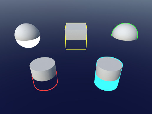
Use the Quick Outline tool for your next project. Find this and more particle & effect tools on the Unity Asset Store.
this does exactly what I want
and it's barely any code
this has me leaning hard into saying f*ck shader graph
i'm having a lot of trouble figuring out how shader graph works. like, i tried looking at this official unity tutorial but it asks to make an Unlit Graph when it doesn't seem to exist any more https://learn.unity.com/tutorial/introduction-to-shader-graph
welcome to the club 😅
for the unlit one, you should see it if you are using URP or HDRP
i believe that's incorrect
unity made a change recently, where they got rid of Unlit Graph and PBR Graph
and i'm aware that they moved it to URP Lit Shader Graph and URP Unlit Shader Graph

ah yeah, I was thinking URP Unlit Shader Graph was what you wanted
because there is an unlit graph under that URP menu there
I am super new to shaders in unity so don't listen to me lol
i haven't gotten to the part i'm having trouble with yet
so i try to make an unlit shader graph, but in the tutorial it's supposed to look like this when i open it up

but when i make it myself, it looks like this

yes, I asked about this exact discrepancy earlier
the "Unlit Master" is missing
and so are lots of options it had, that are used in a lot of tutorials
and i don't see how i can follow along with the tutorial that i linked even if i make an unlit shader graph, because the node that populates looks very different
I am 100% in the same boat
so if someone could give me help regarding this, it would be immensely appreciated
This is just what shadergraph is like now
There is nothing wrong
if you change the graph settings to use alpha clip then it will expose the alpha and clip threshold parameters
@stray badge @elfin dragon
how would i change the graph settings to use alpha clip?

oh i see
what does the Vertex node mean?
@elfin dragon there's probably better resources out there that are more closely related to unity, but this is where I learned about shaders https://learnopengl.com/Getting-started/Shaders
it is GLSL and code based, but it covers a lot of theory
https://learnopengl.com/Getting-started/Hello-Triangle this too covers a lot of syntax
so I guess, it might be useful to you for syntax/theory purposes
Alpha clip materials should most of the time not be marked as transparent
that makes sense
what about this node though? what does it mean?

(i'm brand new to shader graph so apologies for what may seem obvious)
you don't need to touch it unless you want to do vertex offset stuff
like, if i want to make an object wobble?
Sure
Hello, my triplanar shader doesn't apply normal map to generated meshes but does for other meshes. Any pointers would be great
Assumed Mesh.RecalculateTangents(); was needed after the mesh was created but this isn't the case
that makes sense
thank you for your advice 🙇
how to access HDR color's intensity via c# script
guys just out of curiosity, how powerful/flexible is shader graph compared to coding from scratch??
Hi there this is a very basic shader question, but how do i get out Just X, Y, or Z from the Position node? Instead of the vector3

use a split node
much appreciated!
@stray badge I have used those 2 techniques for outlines that you posted, especially for the blurring, do not use shadergraph haha, handwritten is so much butter for that kind of stuff
@stray badge custom function node referencing a file = ability to do everything the way you want to and just use shadergraph to pass you the inputs and setup the shader the way unity expects it.
@tired canyon taking this over here since it's more appropriate
can you tell if I missed anything with the depth buffer thing?
I have
RWTexture2D<float> depthBuffer;

void CheckBvh(Ray ray, uint2 pix){
  float distance = depthBuffer.Load(pix);
  //do bvh stuff
  //...
  if(shape != USHORT_MAX){
    hits[...] = 1;
    depthBuffer[pix] = distance
  }
}
I shouldn't need to touch it in between dispatches right?
Looking at the texture in the inspector it doesn't seem to change at all
it just remains pure red
Spotted this post box in the real world that made me think the shadow normal bias value is too high

I think that it will show pure red for values > 1?
try picking an arbitrary distance like 1km
and dividing everything by that
before putting it into the texture
and see if you see some variation
oh, i figured when the textureformat was set to RFloat it would map the range over the size of the datatype
it's mostly just for precision
remember that a 32bit float goes up to like...
10E32
or something stupid
but you still only get 7 decimal places of precision
regardless of where on that scale you end up
oh I thought it would just take whatever number, and use the remaining bits for precision
I'm pretty sure that all color values are expected to be in the range of 0 -> 1
I think normal depth buffers map that to near plane -> far plane
or just 0 -> far plane
oh yeah, you were right. having distance/FLOAT_MAX has the box show up in black on the texture
haha yea I ran into the same thing
@regal stag Hello! I'm using your supgraphs for custom lighting and they're awesome! One question, how can I add additional light shadows with those?
If I recall correctly they should already handle additional light shadows too.
If you're using the Custom Functions instead of the Subgraphs then you'll need the correct keywords setup though (which are mentioned in the hlsl file above the AdditionalLights_float function).
(Also, if you're referring to point lights - URP only does shadows for point lights in v11 / 2021.1)
I'm using 2021.1, it seems like it doesn't really shadow the back of the object.. Or am I doing something wrong?

Shader is based of your toon example
Do you have keywords for _ADDITIONAL_LIGHTS and _ADDITIONAL_LIGHT_SHADOWS setup in the Blackboard?
Yes, but I don't see if they're used or not

References are the same as the names and settings are set as you said
Then the shadows should be working afaik. Maybe it's something to do with how the AdditionalLightsToon_float does calculations? I think it only works with full shadow strength.
Might be a good idea to try the regular AdditionalLights and see if the shadows work there. If not, maybe changes with URP broke it. 🤷
For some reason when I'm trying to add additional lights node my shader graph just breaks

Hi. I have a noise function that i am using to generate a 2d texture using c#. I want to try to convert this to a compute shader to speed up testing and performance but it seems as though i cannot call my noise function in the compute shader. the noise function is a separate static script so that i can globally access it.
Hi everyone, I am making a stencil mask shader. Currently, it works as intended, the only issue being that it still draws outlines, even though the object is not rendered:

Here is the stencil mask shader:

And here is a chunck of code that I put inside urp's default lit shader:

Anyone ideas??
Well, you're keeping everything in your stencil test (2nd pic) so why do it?
Followed a tutorial, and because I have pretty much no clue on how shaders work I just followed along
I need to recolor some UI images to show different "teams". The image here is in grayscale, and I want the gray elements to be recolored, but not the white (head) parts. I expect that I'll need a custom shader to apply a color only to specific parts of the sprite. Is there a way I can make a shader that will only recolor the gray if you change the Image component's color? Would I need a separate "mask" image for each sprite?

All right, so, I'm winging it, but is there a way I can make a shader property for a sprite that listens to the sprite field of a UI Image component?
Do I have to use alpha test or transparent shaders to blend between LODs with dithering?
(Android device) If yes, it is heavy, so I have to ignore it and use simple LOD switching without crossfade?
Any solution?
you can make a script that passes the value from the ui component to the shader
not sure if Sprite is a valid property type in shaders though
but you could convert it to a Texture type and pass it as a texture property
I made a shader or lets better say I copied in a shader from a friend and in my unity I see this
undeclared identifier '_MainLightCustomFunction_8823f62fb62a4083a113a33d1377243b_Direction_1' Compiling Fragment program with _ADDITIONAL_LIGHTS Platform defines: UNITY_ENABLE_REFLECTION_BUFFERS UNITY_USE_DITHER_MASK_FOR_ALPHABLENDED_SHADOWS UNITY_PBS_USE_BRDF1 UNITY_SPECCUBE_BOX_PROJECTION UNITY_SPECCUBE_BLENDING UNITY_ENABLE_DETAIL_NORMALMAP SHADER_API_DESKTOP UNITY_LIGHT_PROBE_PROXY_VOLUME UNITY_LIGHTMAP_RGBM_ENCODING Disabled keywords: DOTS_INSTANCING_ON _SCREEN_SPACE_OCCLUSION LIGHTMAP_ON DIRLIGHTMAP_COMBINED _MAIN_LIGHT_SHADOWS _MAIN_LIGHT_SHADOWS_CASCADE _ADDITIONAL_LIGHTS_VERTEX _ADDITIONAL_OFF _ADDITIONAL_LIGHT_SHADOWS _SHADOWS_SOFT LIGHTMAP_SHADOW_MIXING SHADOWS_SHADOWMASK INSTANCING_ON FOG_LINEAR FOG_EXP FOG_EXP2 UNITY_NO_DXT5nm UNITY_ENABLE_NATIVE_SHADOW_LOOKUPS UNITY_METAL_SHADOWS_USE_POINT_FILTERING UNITY_NO_SCREENSPACE_SHADOWS UNITY_PBS_USE_BRDF2 UNITY_PBS_USE_BRDF3 UNITY_NO_FULL_STANDARD_SHADER UNITY_HARDWARE_TIER1 UNITY_HARDWARE_TIER2 UNITY_HARDWARE_TIER3 UNITY_COLORSPACE_GAMMA UNITY_HALF_PRECISION_FRAGMENT_SHADER_REGISTERS UNITY_LIGHTMAP_DLDR_ENCODING UNITY_LIGHTMAP_FULL_HDR UNITY_VIRTUAL_TEXTURING UNITY_PRETRANSFORM_TO_DISPLAY_ORIENTATION UNITY_ASTC_NORMALMAP_ENCODING SHADER_API_GLES30

idk...why
Anyone know what kind of material I need in HDRP for Color over lifetime alpha to work?
Legacy Shaders/Particles/
is the answer

wait I just noticed that those shadows actually worked, but not with the tree object for some reason
hmm
oh my god... I'm so dumb...
Sorry for bothering you Cyan, thanks again for your work on subgraphs!
Same bug here on 2021.1.11 ! and drive me crasy ! i'm stuck on that...
Somebody have a fix plz?

I guess that one of your nodes is a custom function node, and the hlsl file it references may be missing from the project
did your friend also have a file called CustomLighting.hlsl or similar? Check for the custom script node and see what reference it was pointing to
how can i get a single image from a rendertexture besides making snapshot?
but how can i select the desired frame?
cant unity takes screenshots just like blender?
I'm stuck on understanding how the default fog works under the hood
transparent shaders don't get written to the depth texture, yet if I enable the fog they receive it
It just takes the distance to the camera and lerps the fog color to the base color based on the type you select
that's not what I asked, that's the basics of a depth-based fog effect
Unity fog looks like is a screen based effect, and I suppose is also supposed to be as light as possible
therefore the shader should have no other inputs other than the depth, color, power and a rendered frame
the point is that transparent objects do not get written to the depth, therefore a screen-space shader has no info available on how to sample depth for the fog effect on those particular fragments
and yet, Unity's fog gets applied to transparent objects with no issues
I don't know about other pipelines but in URP it's not a screen space effect. The fog is handled per fragment when drawing meshes in the scene. Mostly using the functions in https://github.com/Unity-Technologies/Graphics/blob/master/com.unity.render-pipelines.universal/ShaderLibrary/ShaderVariablesFunctions.hlsl (line 207+)