There's ways. That's one.
You'll have to set a different render texture on the camera, and then set the old one back again.
Or if you want to support MRT (Multiple render textures) you can write to an additional texture the first time, and only have to do the water pass once. So "normally" you wouldn't write the depth because you're transparent. But in this case, you write it to the OTHER texture.
Then there's the way that you could be in transparent, but write depth...that has implications. Like if something goes below the surface of the water after you write it, it will probably be clipped.
#archived-shaders
1 messages · Page 207 of 1
Okay, ima start with just trying to render the depth of the water as a texture. I assume I'd have a pass after my first pass to do that. But, how would I store that depth texture?
Meh, on 2nd thought, like I said above, just use a separate camera. The "danger" is that you write too many pixels unless you copy over the opaque pass's depth buffer, or can grab the info from _lastDepthTexture (or something like that, read up).
There's also Camera.RenderWithShader I think.
I feel like i'm being kinda dumb, but I have no idea how to go about doing that
This is the kind of thing I shouldn't comment on, since I haven't tried it (although I've messed with such things, I don't have your use case). It's the kind of thing I'd have to screw around with and experiment and benchmark different options.
Hey man, it's easy for me to just type stuff, but like I say, it's hard to get working.
I know the feeling.
Sebastian just said "oh, I did this" and probably played with it for a day. lol
Haha yeah
You can set up multiple cameras.
You can use command buffers.
You can use layers to isolate things.
All these are good things to read about.
And you can use C# to create render textures.
Well, I believe what he does is have a separate camera for the sole purpose of rendering the depth texture
There's also a COLORMASK thing that will let you tell the shader to not write to the color buffer, then it will only update depth. ShadowMap passes do that, IIRC. They only output depth, so that's something to go looking for.
Yes, he said that much. And it's partly why we're talking about that. 😉
And you may not need to care if you update depth for the water IF IF IF IF IF the water is the last thing you write before the fog stuff. Then you could, if you wanted, just have it update depth, because nothing else besides fog will be coming down the pipe, it's already blended with the other things before.
I don't even know what's being rendered first/last. I don't think I can see that because I'm on linux
If you put the water shader at a transparent queue + 15, it will work. I don't remember the exact syntax, but you can do "Transparent+15" I think.
Meh, I think I want to do the camera, that solution seems like it would be very situational and come with a heap of problems on its own, although it would probably work
OK, cool. I mean, I can sit here and invent stuff for you all day, but it's up to you to work it through. 😉
Camera is pretty easy. You'll have to make a RenderTarget for it in C#
Time to spend a billion hours researching... ah I wish I had the resources he used in the video
I can't even be sure what you want. What "information", precisely, do you wish to pass?
I guess I could explain exactly what I am trying to do, I don't know what the best way is or if there is a way.
Anyone good with normal in Shader with Tessellation?
I try many way, from vextex or surface shader, and there is always something going wrong...
At the moment the closest I have is that, but as you can see all normal seem to be inverted, and I find no way to fix them. So if you have suggestion go ahead, willing to compensate.

I need to know if the original mesh that the material is on is in the current pixel or not when the mesh's vertices are scaled up.
I don't understand that statement, maybe it's just me....
I am very bad at explanations probably not you
Output the normal color instead of the texture color.
See what it is doing.
Some will be black if negative.
RD, you're doing TWO passes at least, yes?
yes
How much info goes between the two passes? I read you to say you need the information per-pixel.
What data? Can you use a stencil?
@meager pelican will do
I don't know much about stencils
Think of it this way:
There's a texture that is storing the colors for each pixel...the RGB and maybe A. That's one texture as a "buffer" to store data.
If i can do it with a vert/frag shader and without anything outside of the shader then yes
Then there's the depth buffer. Sometimes there's normals stored in the depth/normals texture data "buffer".
Then there's a stencil buffer (usually 8 bits). Unity uses some of them.
Depends on when/where it is used what is available.
A vert/frag can use stencil, sure.
ok
Without any fix...

Sounds like a stencil is something I should give a try then
At least worth researching.
With DDX method in surface

@crisp ridgeit looks like a slope/cliff
Thanks, I thought stencils were something like rendertextures which I am unable to use
yes the tessellation part SLOPE between river bottom and land...
wirefram view, not easy to see

I see it, thanks.
@meager pelican So, I have a second camera that is only rendering the water, and it looks like I can make a script that renders the depth texture from that (the water is transparent so I might have problems but I'll figure that out), however, inside the shader how would I access that depth texture? I have no idea how I would differentiate between the depth textures that both cameras render
Well, I don't do much tesselation, but I'll look. Maybe some others will be able to help.
I suggest, if you can, that you pastebin your shader.
The green on the normals output suggest that it is pointing up. But then again, the blue should be green. lol.
You have to decode the normal to get it into worldspace properly. It is stored in a special format.
@wary jackal Maybe you can cheat and store the depth in the red channel instead. 😉
Yes... but with no way to visualize it easily, never easy..
Will see what I can do for the code, since I use an array to generate the land... so will try to make a "self working" version
Thank
If you generate it, you can generate normals for it at the same time @crisp ridge
That's the question... how? I try with the DDX method, I try inside the vertex shader by using 3 points, nothing seem to work.... tried lot of stuff over a week 🙂
Hang in there
So do you generate it in a shader, a compute shader, or in a C# script?
I mean before tesselation
    {
        float2 positionWS = TransformObjectToWorld(v.vertex).xz;
return;
        HexData hexes = ComputeHexData(positionWS, true);
        if(hexes.Hex.IsWater)
        {
            if(hexes.weightHBC.x >= 0.99)
            {
                v.vertex.xyz = v.vertex.xyz + _DisplacementAmount * float3(0,-1,0);
            }
            else
            {
v.vertex.xyz = v.vertex.xyz + v.normal * displace(hexes, hexes.weightHBC);``` {
float3 black = float3(0, 0, 0);
float3 ultraWhite = float3(1, 1, 1) * 3;
float displacementRatio = smoothstep(0, 1, (weight.x > 0 ? (hexes.Hex.IsWater ? black : ultraWhite) * weight.x : black) + (weight.y > 0 ? (hexes.Bridge.IsWater ? black : ultraWhite) * weight.y : black) + (weight.z > 0 ? (hexes.Corner.IsWater ? black : ultraWhite) * weight.z : black));
// float displacementRatio = clamp((weight.x > 0 ? (hexes.Hex.IsWater ? black : ultraWhite) * weight.x : black) + (weight.y > 0 ? (hexes.Bridge.IsWater ? black : ultraWhite) * weight.y : black) +(weight.z > 0 ? (hexes.Corner.IsWater ? black : ultraWhite) * weight.z : black),0,1);
return (1 - displacementRatio) * _DisplacementAmount * float3(0,-1,0);
}
that how I generate the "displacement" after tessellation
using Better Shader, but can translate it in pure HLSL if needed
Well, IDK enough about tesselation to know for sure, maybe someone else will.
You may wish to show how you attempted the normals calc.
Inside Surface
//            float3 dpdy = ddy(d.worldSpacePosition);// * _ProjectionParams.x; // Needed since the land is rotate 90 degree
//                o.Normal = normalize(cross(dpdy, dpdx));
                float3 displacedPosition = position + v.normal * displace(hexes, hexes.weightHBC);
                float3 neighbour1 = float3(hexes.v1.coord.x, 0, hexes.v1.coord.y);
                float3 neighbour2 = float3(hexes.v2.coord.x, 0, hexes.v2.coord.y);
                float3 displacedNeighbour1 = float3(0,0,0);// neighbour1 + v.normal * displace(hexes, hexes.v1.weightHBC);
                float3 displacedNeighbour2 = float3(0,0,0);// + v.normal * displace(hexes, hexes.v2.weightHBC);

                // https://i.ya-webdesign.com/images/vector-normals-tangent-16.png
                float3 displacedTangent = displacedNeighbour1 - displacedPosition;
                float3 displacedBitangent = displacedNeighbour2 - displacedPosition;

                // https://upload.wikimedia.org/wikipedia/commons/d/d2/Right_hand_rule_cross_product.svg
                float3 displacedNormal = normalize(cross(displacedTangent, displacedBitangent));
v.normal = displacedNormal;```that's inside the fragment one
Let me ask you this much....do you know the 3 verts of a triangle in there somewhere after tesselation?
If you do...the normals can be calculated from the 3 verts.
I have the position that is one, and using the displacement and an offset I create 2 other
But it isn't working.....
Maybe it is an object normal and has to be translated to worldspace?
At least the way I calculate it... maybe there is an error in the code I found
v.Normal is in object normal... not worldspace
so I need to convert v.Normal to worldspace then back to object space?
IDK, I'm a bit lost at this point, I don't do tesselation. And you've got a lot going on.
But you do have to transform the object normal in a regular vert. Because you also transform the verts.
ok... will certainly do some test keeping that in mind...
it's true that my 3 vertex are in worldspace, but the v.Normal is in objectspace
Yeah, and your comment said something about rotating the thing. Maybe that's why we saw "blue" on the top rather than "green" that we should see. (Green being an up vector).
I think I'm getting somewhere maybe. I have a camera that is rendering just the water to a texture. I want it to render the depth of the water though, and I don't know how to do that. How would I go about that?
yes... if I rotate my plane 90, I need to * ddy by proj x... but at the moment I brought it back to 0, to remove that from the equation
The pic in this post ^^, is that showing with the camera having an UP vector along the Y axis like normal? Because up is green.....
But if you've rotated the camera in worldspace, IDK what I'm looking at. Blue is the Z axis.
that's the editor camera
You're calcluating the 01depth now, right?
Set color.r = to that.
And just use r. Easier.
Otherwise outputting depth comes from the vertex shader's value.
Is there a way to swap them from Y to Z ?
You can rotate vectors, but never mind that.
What is the picture telling me?
Why is the top blue? Is the land rotated or not?
Is up still up in that pic?
The land is not rotated, and Y+ is up
Then it should be green not blue
Because for a horizontal surfcace, the surface normal is (0, 1, 0).
See what I'm saying?
Yes, but normals are encoded.
ok
You have to decode them.
unpacknormal
They do that to avoid negative numbers in normal maps.

Well, that's the texure, not the normals.
My bad
But it looks nice 😉
Okay, now I'm running into another problem, but once I solve this I think it will work. I want the waterDepthCamera to render the water as opaque, but the Main Camera to render it as transparent. I assume I need separate passes for that, but how in the world do I separate that by camera?

You have to decode them I think.
I do unpack... but they are blue, I think that bettershader do it "afterward"
return UnpackNormal(SAMPLE_TEXTURE2D(tSnow_Normal, sampler_tSnow_Normal, uv));
So Green is Y up... that would explan why the ddx is not working
@wary jackal If you store it in red, you don't care.
if BetterShader does something
I don't really understand what you mean by that though... what am I storing in red? and which color's red am I storing it in?
Our first clue.
Yes... so would just "rotating" the ddx make sense in that case?
I mail BS to see if it's normal that we see "encoded" normal instead or normal one
in your special water pass, store the depth in the red channel, and output that as the color. You can have a red-only render texture. No bga needed.
That would make sense, but how do I make it so the water camera only renders the special pass and the main camera renders the normal pass?
waitwaitwaitwait
in sebastian's video he has this: waterDepthCamera.RenderWithShader(waterDepthShader, string.Empty);
is there a way to customize what we consider a "depth test fail", because I would like the ztest to fail only if the difference between the 2 is greater than a certain number 🤔
https://docs.unity3d.com/Manual/SL-ShaderReplacement.html this will help too, explains the tag part of all that.

no, not exactly, But you could offset it in the vert() function, but you probably don't want to write that back out. There are ways to write depth from the frag(), but from what I read, it isn't recommended. Then you could subtract the offset before writing.
ok I will try that
This is a really stupid problem, but the names of the shaders are kinda like files: "Custom/Terrain", etc. In the RenderWithShader function how would I include the "/" and stuff?
It's probably best to offset the verts along the camera normal, but I'm unsure. Changing the z value after transformation into clip space will require you do mess with more maths I think. But at any rate it has to be scaled by the far-plane - near-plane distance somehow. I'd have to mess with it.
Will wait for answer.... but "cheating" the axes seem to give me a good result at the moment 🙂
I don't understand, it's a string....
you either include it, or you just say "terrain". I'd have to mess with it.
It's not a string though
It doesn't take type string, it takes type shader, and when I type the name of the shader (with or without the "Custom/) I still get an error
When then you can use Shader.Find() I think it is.
okay
@meager pelican thank for your help, last question, those small BLACK line, I assume they are "inverted normal" ? Any way to detect them?
My goal is to prevent my roads to clip through the terrain, but at the same time they should not be visible through any mountain :

If this could be done without creating holes in the terrain under the road that would be great, that's why I thought using stencils might be a good idea
You already have depth though! The depth of the road should be greater than the depth of the green-hill, so the green-hill should be closer, and it should overwrite the road. Unless you're writing the road after the hill, and you're ignoring depth.
That's conceptual, not actual. Because unity sorts things out.
And IDK how yours is sorted.
are you outputting depth on the terrain?
awesome! My second camera is rendering the water with its own custom shader...
IDK, I'd wait until it's rotated properly first. Normally (ha!) normals that point away from the camera are culled (backface culling) and if it is rotated wrongly.....
Cool. So if you render that water-depth camera BEFORE your fog shader then you can pass that render texture to your fog post processing pass along with any other info.
I gotta figure out how to get the depth of the second camera
Its me.... once again. Is it possible to do custom operations on the stencil buffer?
depth is weird.
yes it is.
Careful. It's easier to use red.
yeah, but I still need to get the depth of it
depth is just a number. You can store it anywhere.
you can encode it, or not, etc.
sort of, you'll have to read up on it. Did you check the docs?
yes
Well, those are the options you can customize.
hm
I essentially want smooth min function on it when adding to the buffer
Well actually smooth max.
It's more like a bit-mask
IDK, and it may vary by hardware, not sure.
ok
How would I combine the two depth textures?
You mean in order to do the fog?
yeah, I just want to combine the main camera's depth texture + the second one (the water)
I suppose
float myDepth = min(worldDepth, waterDepth);
I think that's what I did
For the road I have "Queue"="Geometry" and for the terrain I have "Queue"="Geometry+1"
hmm, I'm using _LastCameraDepthTexture to get the texture but I don't think this is working, I seriously don't know how to get the depth texture of my second camera. It's probably time to start using the red value as the depth 😛
That's probably not the most efficient way, but it should still work.
depth is weird. Use red Mateu
Okay, so how do I turn the depth texture of the water into the red value? because _CameraDepthTexture always uses the main camera's depth texture.
You have a variable that is holding the linear01depth now, right?
in its own pass
float waterDepthValue = Linear01Depth(tex2Dproj(_LastCameraDepthTexture, UNITY_PROJ_COORD(i.screenPos)));
oh wait no
that's in the fog shader
Well, if you're rendering water, it's the depth of the current pixel.
So, if I did _CameraDepthTexture this would not render my opaque water.
Because it might cause some issues with some camera angle ?
OK, for this special pass, forget depth textures exist.
Okay.
take the current pixel's depth value (which is a float 01), and output it as red.
You only need a red float texture assigned to the camera.
use red32 to get highest precision.
How do I get the current pixel's depth value?
You know that from your water shader. It's doing it now.
You compare that to the terrain depth and take the diff.
I think.
Oh really?
So I don't want the LinearEyeDepth though?
Or maybe it's just the .w
I believe it's just the .w
that gives you worldspace
okay, so I want screenspace
But whatever you want, to compare to the other, you want them the same.
Sure.
if that's what you're using for the other.
Yeah cause that's what I used
Then you can take the min() of them.
okay, let me try that.
That gives you the closes of the two. But be careful of non-water pixels.
I masked out everything else 😛
cool
well, it's the sky but the min function should take care of that
So, how would I make the camera's render texture always be the size of the camera's screen?
Once it is in clip-space, it will range from -1 to 1 I think it is, but then it gets a perspective divide by .w at some point. My brain hurts right now. lol.
or, I guess I could just do some thing along the lines of 16x9, because that's what the game screen is forced to be
Linear01Depth (tex2Dproj(_CameraDepthTexture, UNITY_PROJ_COORD(i.screenPos))); In this function, how would I not use the camera's depth texture to get the depth? would it be i.screenPos.xy / i.screenPos.w?
There's code for that.
you get a temporary render texture, and hang onto the reference.
When you get that (create it), you pass in the screen.width and screen.height values in the call. Then later, when done, you have to release it.
https://docs.unity3d.com/ScriptReference/Screen.html
https://docs.unity3d.com/ScriptReference/RenderTexture.GetTemporary.html
I'll just set it to some factor of 16:9 ratio. Won't be perfect but it'll probably work. Keyboard probably
okay, but as for my second question, the (tex2Dproj()) needs a sampler2D as the first argument... usually that's the camera's depth texture.
@Sevasson you shouldn't have to offset them, but frankly I'm lost as to what you're up to in your whole approach.
Hi! I'm assuming surface shaders do their specular term in the fragment shader right?
I don't really like them and I program all of my shaders in vert/frag but I have that curiosity regarding surf
I want to prevent the road from clipping through the terrain :

all of this is procedural because it's a 3D city builder
I know I could raise the road to prevent this but I want the road to be at the same level as the terrain
@meager pelican so I did this: float depthValue = Linear01Depth(tex2Dproj(_LastCameraDepthTexture, UNITY_PROJ_COORD(i.screenPos))); and set that as the r value of my return color. However, it's just solid red
If I use Stencil { Ref 1 Comp notequal } for the terrain and Stencil { Ref 1 Comp always Pass Replace Zfail Zero } for the road, the road does not clip through the terrain anymore but I can see the road through a mountain and that is a problem 🤔
Don't use _LastCameraDepthTexture. That SOMETIMES works, but wow. Depth textures are weird.
Use the current pixel depth.
I tried, but it requires a sampler2D
I have no idea how to get the depth of the pixel
Why, you shouldn't have to sample anything. OK, second.
Use COMPUTE_EYEDEPTH(i) in your vert().
I'm not sure their docs are correct, but try UNITY_OUTPUT_DEPTH(i) in the frag and see what you get. See the example here, theoretically it outputs object depth in the example:
https://docs.unity3d.com/2020.1/Documentation/Manual/SL-DepthTextures.html
It claims UNITY_OUTPUT_DEPTH(i) returns 0 if there's native depth textures, but then the sample program wouldn't work....
Spit balling.
I'll have to go find those macros.
So should I put UNITY_OUTPUT_DEPTH inside of the Linear01Depth function?
Nah, I'm finding them. That's an encoded depth. Forget it, my bad. Weird example though
Anyone?
Well, a surface shader is just the combination of a vertex and fragment shader, so, yes.
Surface shaders are just meant to make life easier, although I do agree with you, I prefer making my own vert/frag shaders
Yeah I know that but specular term can be done per vertex or per pixel
So with a custom lighting model (Standard is obv per pixel) I have no way of knowing if the data I'm sending goes to vert/frag
It's done in the fragment shader.
You can look at the generated code and see what their surf functions and light functions do.
Because it wouldn't make sense for lighting to be on the vertices
agree
Yeah I'm just not home atm
It's not that bad to look at, there's just a bunch of variants to wade through, but in the end, their surf function calls your surf function, and then continues on. And there's the various passes.
Only for really slow old devices that's what I can think of
Anyways thank you very much!
yeah
np
Okay, I tried Linear01Depth(i.screenPos.w) and it turned black, so everything returned 0
Yeah, forget that.
OK, try this in the vert()
COMPUTE_EYEDEPTH(outVar);
And then you'll have something in the frag, but IDK what scale it is.
Yet
okay I'm getting errors when I do that
I just did COMPUTE_EYEDEPTH(o); and there were two
Shader error in 'Custom/WaterDepth': invalid subscript 'vertex' at line 54 (on glcore) I always change the name vertex to position
and ```Shader error in 'Custom/WaterDepth': 'UnityObjectToViewPos': no matching 1 parameter function at line 54 (on glcore)
OK
outVar = -UnityObjectToViewPos(v.position).z
But IDK exactly what space/scale that's in.
It's in view space, of course, but it's not going to be 0-1 yet.
do I need a subscript for o?
Yeah, where ever you put it.
oh, so this would be its own variable?
IDK, that's you programming.
I'm just confused on what COMPUTE_EYEDEPTH does
"COMPUTE_EYEDEPTH(i): computes eye space depth of the vertex and outputs it in o. Use it in a vertex program when not rendering into a depth texture."
It does this:
outVar = -UnityObjectToViewPos(v.position).z
oh okay
okay, that's working
I just think "position" is more logical
like, that's what type of information vertex stores so why not call it position
okay, well that is working now. But it's still not in 01 format
Right. It's in view-space
Well, don't I want it in view space? Or is that not what I want
That's where I think linear01Depth comes in.
That is
{
    return 1.0 / (_ZBufferParams.x * z + _ZBufferParams.y);
}```
But it's really old google result. May have changed, IDK. But you get the idea. I should look it up in current shader source.IDK, I'm not coding your shader. lol
what do you want?
yeah, I did this : float depthValue = Linear01Depth(i.depth); and it's still all black
And you did the other to o.depth?
yeah, I did this in the vert o.depth = -UnityObjectToViewPos(v.position).z;
oh wait, maybe it's because I'm not using the screenPos
I have no idea what I'm doing. I thought everything was figured out until I needed to find the depth of the pixels
If you want the world space depth (view space), you have it.
The worldspace depth is a value <= one, and that doesn't help me all that much, maybe I need to pass more parameters into the Linear01Depth function
No, viewspace depth is in world units, with the world rotated to fit the camera.
I think
I'm getting punchy, and have had 2 phone calls and a bunch of text messages while I'm typing. lol
Yeah sorry, I don't want to make this your problem, Maybe I can figure it out myself
Just trust me that switching around depth textures is hard, and _LastDepthTexture is flaky last I knew.
As far as what you store in the red channel, it doesn't matter that much as long as you deal with it properly during your fog shader (that I haven't seen).
Let me doing it that way
So if that compute view-space-depth works, even if it isn't 01, then great, you've stored the depth of the pixel in that special pass. Next is you figuring out how to deal with it during fog calcs.
Wait, I thought you were using red, and the _LastDepthTexture didn't work.
Yeah I was
Because depth-texture values are encoded.
Sometimes, if it is using a depth texture (as compared to buffer) at all.
@wary jackal LinearEyeDepth from the real-shader depth-buffer might be in the same scale-space (view space) as the other value you got from your special pass. You could divide it by the far-plane to get 01, maybe add near-plane to it. LOok up the linear01depth macro.
I think i'm going to stop for now. Thanks for your help, and I hope I didn't frustrate you. Maybe I can pick up on this sometime later when I can actually think
Hope I didn't mess you up. It's hard being 2nd party to it and not working though the code from here.
Have a good night 🙂
Hi all, I'm new for unity software. anyway, really glad to be here and unity have shaders channel. I have problem with outline shaders, I follow all steps by this tutorial https://youtu.be/U51yrbgBmAo (except vector1, I change it to float) and I end up like this, the line is too big, I get stuck and try again the tutorial and cause same problems, hopefully anyone can help, thank you


Pokémon Mystery Dungeon: Rescue Team DX features a bold, unique visual aesthetic, emphasising thick outlines on characters and shadows using a drawing technique called hatching. In this tutorial, learn how to use Shader Graph to take any model and make it look like it's been drawn in a style reminiscent of PMD!
✨ Read on my website: https://dani...
Hey, I have an array of textures:
sampler2D Atlas[6];
(I tried using Texture2D and one sampler, didn't work)
and I want to sample them using a given certain input to the shader.
I can't seem to sample the texture array, I must use literal expression to index the array (Atlas[0], Atlas[1], can't do Atlas[index]), so I did something like this:
switch(index)
{
  case 0:
     // sample at Atlas[0]
  break;
  // ....
}
And it worked great, the shader finally got compiled and sending one texture to the array worked great, BUT as soon as I send more, I get the attached message, As I read it seems to be the GPU that stall's and the OS shut it down, but I can't figure out why it does it

I debugged my code, I send the right values + textures, the only problem is the switch and the sampling of the texture at that part, when this code is removed and I simply change the sampling of the texture to color = half4(1,0,01); everything runs smoothly, nothing gets crashes (I assume its because the compiler optimize the shader maybe)
Hello, I would like to know if geometry shaders work with single pass instanced rendering. I've already looked at the first threads shown after a quick google search.
Have you tried using the Texture2DArray object? (assuming your target platform supports it)
https://docs.unity3d.com/ScriptReference/Texture2DArray.html
On the shader side, it's Texture2DArray name; SamplerState sampler_name;. Sample it with the z coord as the slice index.
https://docs.microsoft.com/en-us/windows/win32/direct3dhlsl/sm5-object-texture2darray
@regal stag My texture are different in sizes so I can't use Texture2DArray, I am now trying to make them the same size so I can try to use it though
It does mean that I'll need to resize small images to my max texture size
Probably yeah
I just got into programming shaders, I wanna ask why isn't something like this the defualt for unity?

Get the Better Shaders - Standard/URP/HDRP package from Jason Booth and speed up your game development process. Find this & other Visual Scripting options on the Unity Asset Store.
With shader graph atleast they could implement something like this
Where we could take the outputs of one shader graph in other as inputs and modify them
That's potentially a long question to answer, but this interview is as close as you will get to one
https://www.youtube.com/watch?v=UtNpc1tmCmU&t=11s

Join us this month as Jason Booth, graphics wizard of legend, presents on the current state of Unity's various render pipelines, authoring shaders and how he's working hard making life easier for the rest of us!
Description: Unity introduced the Scriptable Render Pipeline, along with LWRP, URP, and HDRP, each developed by separate teams that we...
Should I wait for unity to implement something similar or buy this instead?
depends on your timeline for launch mainly, I would not expect unity to suddenly have anything close to this production ready for over a year even if it was announced tomorrow (nothing announced to my knowledge yet).
I'm not launching that soon for sure
I'm just a bit hesitant because other assets won't always have integrations for it
if you watch the talk, it explains a bit more than perhaps the promotional videos do. I would only buy it if you are comfortable and confidant in writing code shaders yourself or team member is to get full benefit from it as a product. TLDR I don't want to give wrong impression, watch the vid 😄
it depends on everyones own position as to what is best
Did ya try it?
Yes it worked, the problem came from elsewhere. I started from a simple shader and added the geometry part instead of iterating on an existing shader
hi, i tried making shaders, but when i put them on an object, they turn out pink. is there a solution for this?
Tips? You're in a tight spot!
The simple lit shaders don't support reflections, as you've noticed.
If you switch to lit shaders, you get PBR (a little more expensive than blinn-phong), and as you've noticed not the same as your old workflow.
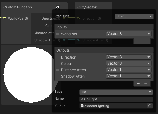
This is a good time to stop and think about what direction you want to go in, going forward. Convert the looks of the old system to the new system, changing the old-ways to look OK in the new way using the lit shaders, or trying to reinvent the wheel by doing your own custom lighting in the new pipelines.
There's articles about how to do that, but things like shadows seem to be a problem right now. Shader Graph isn't really set up to do a custom lighting model that I know of, but maybe it's on the horizon. It would be nice if they had a simple lit Blinn-phong model alongside the PBR model, or something.
So in the end, you can try it. If you don't need shadows, you can do the calcs yourself in shader graph without much trouble.
See https://blog.unity.com/technology/custom-lighting-in-shader-graph-expanding-your-graphs-in-2019
@regal stag has a write-up too, about getting Shader Graph to do shadows using the above "custom lighting", but it still won't include reflection probes, which you'd have to add in as well (but SG has that available, see https://docs.unity3d.com/Packages/com.unity.shadergraph@6.9/manual/Reflection-Probe-Node.html).
Cyan's write-up that augments that tutorial above: https://cyangamedev.wordpress.com/2020/09/22/custom-lighting/
All in all, it's a bit complicated, but doable to do your own custom lighting, I'd start simple, and follow the tutorial and Cyan's example, be warned that so far shadows aren't working for me, but that might just be me.

Hey! Wrote this up as an answer to someone on the Unity Discord. I had plans to extend this, but probably wont get around to it as I’ve moved to a new site. But it still possibly provides a b…
I'm trying to learn compute shader I made a simple shader where there's two textures that I ping pong between them and I increase the red value every frame the problem is when the value is too small like 0.001 it doesn't work anymore why is that?
What is the texture format of the textures?
I didn't set it so I actually don't know it's a RenderTexture
Hmm. To get the most floating point precision, you'll want the most bits per pixel that you can afford on your platform.
https://docs.unity3d.com/Manual/class-TextureImporterOverride.html
Such as RGBA 32 bit, then there's compression/format. Something to research.
Also your shader should be using full floats, not half or fixed.
I see, so the problem is it's considering small values as zero's?
I'm using tex2Dlod to load the pixels
But in the end, the output device (screen) is probably only going to support an 8 or 10 bit result for each color.
That's just the function call, not the format.
Floats have various sizes, in textures and in variables/memory. And the more bits, the more precision it stores. But like I said, in the end it all gets converted to X number of bits to send to the screen. But for intermediary calcs, more precision is often needed. Depends on what you're really trying to do. Floating point has limitations. Even some numbers that it cannot fully represent accurately!
I see, the thing is I wanted to slow down the process of color interpolation from black to red in this case, i will have to either change the format or do less execution right?
Yeah, if you're just having a timing issue, "less execution" is better.
You'd have to decide how much per second, and then use Time.deltaTime in your code to figure out if you've crossed a threshold somehow, with some maths however you want to do it.
You want to make it frame-rate independent and then have some slider or something somewhere that let's you set the transition time.
Or you could just do a lerp, based on some time fraction.
I see thanks for the help I'll try it out

Make all your sprites black?
and how do i do that in unity?
I mean, don't start with regular sprites that have color
Just have them completely black to start with
But you can also change the sprite renderer color to black
i mean i camt
thanks i will try thay
that
hi, my shaders arent working in URP, but in normal unity 3D they are, is there a way to fix it so that they do work in URP?
@meager pelican Thank for the help yesterday, still not get exactly what I want but getting close 🙂
You have to rewrite them. CGPROGRAM shaders only minimally work, and surface shaders dont work at all
i recommend this guide https://www.cyanilux.com/tutorials/urp-shader-code/
Explains how shader code (ShaderLab & HLSL) is written to support the Universal RP
ohh thanks!
if you are trying to continuously support multiple pipelines at the same time with minimal effort you should check out https://assetstore.unity.com/packages/tools/visual-scripting/better-shaders-standard-urp-hdrp-187838
Or wait for shadergraph to support built in and use that for shader authoring @plush phoenix not the best option, but one of them
with this i didnt use shadergraph but the custom shaders
@meager pelican finally get an acceptable solution and quality... tessellation is not perfect, and sometime require a specific angle to be perfect, but it's working fine... Really much appreciate the help, if there is anything I can do, let me know...
Are compute shaders written in hlsl? Or is it a different language
Mine are written in blood and sweat
Hey All! I'm having difficulty trying to have this shader scroll downwards only, and have the black of the texture stay black, and the white become an emissive color of my choosing. How can I do this?

Put the Time node into the Y input on Vector2 before putting into Tiling And Offset.
Put the output of the texture into the T input on a Lerp node, the A and B inputs can then control the colour of the black/white parts. Or if black is going to stay black, can just use a Multiply node to change the colour.
I can't really find an answer online but just to make sure in a compute shader if you put 1.#INF or #INF after a number when initializing it, it'll be the highest float right?
Like
float a = 1.#INF;
hi, i have this one error in my shader
Unexpected identifier "fixed4". Expected one of: typedef const void inline uniform nointerpolation extern shared static volatile row_major column_major struct sampler or a user-defined type
idk if this is because its in URP, or if its just an error in the code, but does anyone know how to fix it?
It's likely a code error. Can you post the code and line number if you have one?
Before you do that, though, check to make sure your curly-braces are matched, and that you have semi-colons in the lines above where required and also closing quotation marks.
The error sends me directly to the first property, which is
_Color("Main Color", Color) = (1,1,1,0.5)
Then post the lines from the top to that line, so we can se what comes before it....
Don't forget the 3 ` 's around it.
The bot will delete your post and mute you if you post raw code sometimes.
{
    Properties{
_Color("Main Color", Color) = (1,1,1,0.5)```thats all thats above that line
URP / HLSLPROGRAM doesn't include the fixed type afaik. Use half instead, or float.
ohh okay, thanks!
sorry to cut in if I did, but does anyone know what is faster?
- using an alpha channel and putting the shader on the transparency render queue
- using grabpass and adding to the tex2Dproj texture
- something I dont know about yet
Can I get another opinion on a problem I'm having? I've been working on this for hours and I've hit a pretty major roadblock, and I just don't have the knowledge to proceed.
I have a water shader that is transparent, so it doesn't write to the camera's depth texture. I have a post processing fog shader that uses the camera's depth texture to create the fog effect. However, the fog goes straight through the water and kinda breaks the illusion. My solution in theory, should go something like this:
- Create a second camera that only renders the water plane
- Put a script on the second camera that renders the water plane using an opaque shader
- Have the camera render to a texture
- Have the camera render the depth of the water pixels to the r value of the camera's render texture.
- Combine the camera render texture to the _CameraDepthTexture in the fog shader
Those should be the steps. However, I am stuck on #4. I've tried many different approaches, and what I want to do is get the depth value of the pixel and convert it to a value between 0-1.
The function LinearEyeDepth and Linear01Depth seem promising, with Linear01Depth seeming to be even better, because the depth should not be based on world space.
My issue is that I cannot seem to get the correct values for the depth of the pixel.
I've tried a lot of different methods to doing this, a lot of which I found online, but i'm just completely stuck.
*I did get to a point where it did appear to render the depth correctly, but I had issues with that. The two depth textures did not combine so I had some weird effects, and the two waters from the cameras also did not align, so I don't know what's up with that.
might sound stupid, but why not put the render queue differently. Hard for me to visualize but if "the fog goes straight through the water" is what it sounds like then changing the render queue is probably something I would forget when you are programming all day
is the fog rendering over the water? or under
One other option is to do your fog pre-transparent objects, and integrate it in your water shader manually
If you're trying to do #5, just have your transparent water shader write to the depth texture in the first place. There's no rule that says transparents CANNOT write depth, it's just that transparents don't normally occlude. BUT...since your fog is a post process, go ahead and f-up the depth value in the depth buffer, and turn zwrite on for the water shader. Then you don't have to do all that other stuff, unless there's something I don't know about. @wary jackal
Thanks for the suggestions. I did think about rendering the queue different. However, this would clash with one of the effects I have in the water that changes the color based on the view distance through the water. (This requires the water to be transparent, or it would not work)
@meager pelican I do not believe ZWrite actually writes to the depth texture, I think I figured that one out a while ago when trying to turn ZWrite on for my terrain so that it would write to it. There's probably another way though, so I'd have to look into that.
@whole citrus Can you do that with post processing effects? To be honest, I wouldn't really know how to do that.
Would that go inside a camera script?
How do you do your fog atm?
I have a custom shader that is a postprocessing effect. Want me to pastebin the shader?
No thats fine, how do you call your postfx? Via the unity postfx package, or a custom [imageeffect]?
I'm a little confused. I have a camera script if that's what you mean. It renders the scene using the shader
a custom shader that is a postprocessing effect
How do you convince Unity to use your custom shader as a post processing effect? There are a few different ways to do this.
using System.Collections.Generic;
using UnityEngine;

[ExecuteInEditMode]
public class PostEffectScript : MonoBehaviour
{
    [SerializeField] Material mat;
    void OnRenderImage(RenderTexture src, RenderTexture dest)
    {
        Graphics.Blit(src, dest, mat);
    }
}
That's on the camera
Great!
What i would suggest is add this attribute to your OnRenderImage method: https://docs.unity3d.com/ScriptReference/ImageEffectOpaque.html
This will make it so your fog happens before transparent objects are drawn. You can use the Frame Debugger to verify this.
Then in all your transparent objects you need to add your fog logic manually. That is one way to do it, if you have control over all transparent objects shaders.
That makes sense. For the fog logic would I just basically copy + paste the code from the fog shader onto the transparent objects?
Pretty much yeah! You just need to figure out how to get the right depth, distance to the camera.
aaand that there is my problem. I do not know how to get the depth distance to the camera. If I could get that, I believe I would be able to solve my problem. (Everything just comes full circle doesn't it)
Unity Forum
[IMG]
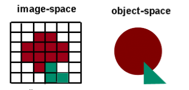
depth buffer.(left)
I need position's depth on right object.
As I know,after rasterization,GPU can "Early Depth Test".
So I think user can't get...
The difference is that now you are just asking your own depth, in the water shader itself.
Vs trying to read it out in a postfx
I've seen that post before. I think I've tried everything that was in it, maybe I'll have to try again
heh, it was actually open as one of my tabs 😛
Actually though, that was one of the closest results to what I wanted.
            v2f vert (appdata_base v)
            {
                v2f o;
                o.vertex = UnityObjectToClipPos(v.vertex);
                return o;
            }

            fixed4 frag(v2f i) : SV_Target
            {
                return i.vertex.z / i.vertex.w;
            }
Seems to work fine here
One moment, let me see what I have
Okay, yes that is working. Now I want to combine that depth texture with the camera's depth texture
Apparently the Min() function is supposed to work, but for some reason it didn't
Maybe visualise both, for example set the red to the depth and blue to camera depth.
What could be happening is that one is in 0..1, while the other is 0..far-clip?
well, the _CameraDepthTexture uses the Linear01Depth function which stores the value as a float
And I can use any pixel value for the water depth. Do I need to get the Linear01Depth for the water depth?
Yooo that's sick. It almost works
I'll show you my problem
The render texture doesn't seem to actually line up with the water, even though it should
This probably has to do with the resolution of the render texture
Okay, well I don't think it has to do with the resolution. I've messed with that. I can't really think of any other reason it's doing what it's doing, unless it has something to do with the space the pixels are being rendered in (idk)
How is this possible ? In the scene view, the road is ok on the main camera window, but not in-game (I use an offset in the road shader) :

postprocessing? Honestly I have no idea that's the only thing I can think of
I got it!!!!!! My field of view for the water camera was different than that of the main camera. Such a simple fix how did I not see it
@meager pelican and @whole citrus tysm for your help... this took me so long to do
I'm new to shaders and I'm working with HDRP. There is like 8 type of shader in HDRP. Some are selfexplain, like Hair, Eye. Cloth etc. But I just want a ''Standard'' one. Most people on youtube use PBR Master, but it's not in HDRP. What is the closest to PBR Master?
There's an HDRPLit shader. That's probably what you're looking for. And there's a conversion process to convert the old built-in ones to the new shader. Standard gets converted to HDRPLit, with some magic.
But HDRP does things differently and there isn't always a 1 to 1 mapping between them. See here https://docs.unity3d.com/Packages/com.unity.render-pipelines.high-definition@6.7/manual/Upgrading-To-HDRP.html for pretty pics of textures. 😉
and here: https://docs.unity3d.com/Packages/com.unity.render-pipelines.high-definition@12.0/manual/Upgrading-To-HDRP.html for the latest. (it has changed over time).
thx alot!
HDRPLit look like shaders in tutorial so I'll be able learn from those
hi all so i want to make refraction node following this tutorial (https://www.youtube.com/watch?v=kgXeo2SRDd4&list=LL&index=3&t=1031s&ab_channel=PolyToots); but it's doesn't work, is there's anything to do with usage of base color instead albedo?, as I know both same.


In this one we us a texture based displacement map coupled with a normal map, both made in Blender (not shown) using the ocean modifier. Really simply stuff, but amazing results. We're also using refraction but not in the same way that everyone else is using it, so that's either good or bad.
● Support Links:
♥ Subscribe to learn more!: https://...
overall node like this, instead img texture, I use custom procedural that's why I need split first. but also try use img texture like vid, it's neither work

I have a quick question about skyboxes. So, materials are spheres, right? So is a skybox basically just taking that spherical material and projecting it to the sky? As if the world were inside the sphere? If this were true, that would be pretty helpful. If not, can you explain what a skybox actually is and how it works with the material?
im trying to apply a green fresnel effect to a white 2d circle. why does this come out blank?

like, i want the circle to look like what is displayed in the multiply nodes
with the black being transparent
Pardon the stupid question, but is setting the whole image a single color a huge performance difference versus setting it up with mutiple color?
For example if I do Albedo = float3(1,0,0) is faster than doing Albedo = color , with the color variable being assign in both case, but only use in the second one.
For me it make little sense, unless the shader compilation just skip huge part of code since he decide the variable is unused in first case.
If anyone have an idea/explanation, it would be appreciate
@crisp ridge I'm probably not the right person to answer this, as I don't know a whole lot about optimization, but honestly the difference is probably so minute that it really doesn't matter. In this situation, do what is most convenient to you. Personally, I don't like hard-coded numbers in my code, and prefer variables, as I can actually see what they do.
So, without the shader you gain 80 fps? Or just with that line of code? @crisp ridge
@timid minnow

Oh
(not sure if it was that way around, flip the inputs to step if it's inversed)
Is that more efficient than this?

Yes
Sweet, thank you again!
I am trying to use shadergraph to create a skybox and I ran into a wierd problem with
3d object mapped uvs
it stretches over other axis

Hi, how can I make particles ignore this object with occlusion shader? Make particles visible before other objects

tell the particle's material to draw before the object you want it to be behind
make a custom particle material based on the one in the particle system
at the bottom you'll have an order setting and you should set it below the object
otherwise the stencil buffer should work but it's more advanced than the first answer i just gave
Hi 🙂 I'm looking into creating a shader that has a particular style.... is it possible to give a texture to the shadows to achieve a dither/stipple effect?
something similar to this but in 3d not 2d

What exactly do you mean by "doesn't work"? Make sure you have enabled the Opaque Texture on the URP Asset(s), and changed the graph surface type to Transparent in Graph Settings.
Materials don't really have a shape. They just hold properties for a shader, which takes an input mesh, transforms positions to the screen and colours it. In terms of the skybox, it's a sphere mesh yeah, the world is inside a sphere. The skybox mesh UVs also just store the 3D vertex positions.
blend small noise into it with the blend node and you'll get some effects somewhat like that. You can blend noise into the normal map of the texture so that the effect shifts with the light
This is expected, as the skybox UVs are 3D. You can remap them though with some Arctangent/Arcsine usage. This should be helpful : https://medium.com/@jannik_boysen/procedural-skybox-shader-137f6b0cb77c
Hmm...thanks I'll give it a go. never did a shader before...tutorials time 🙂
I managed to get it working by splitting the uvs up and combining their counterparts like this

The Fresnel Effect node won't apply an outline, that's not what it's for. It compares the mesh normals with the view direction (so as faces face away from the camera it outputs values closer to 1). It only really works with 3D meshes, not sprites.
If you want an outline, I'd recommend using an SDF (signed distance field) to construct a circle. e.g. this graph, then put into a Smoothstep to better control the edges. And into the T of a Lerp node with A and B as colours to swap the black/white colour out.
If you need to make this work with any sprite, then look into converting your texture to a SDF. I do something similar in this tut : https://www.cyanilux.com/tutorials/sprite-outline-shader-breakdown/

Gotcha, thanks cyan. Ive been watching brackeys tutorials on how to use shader graph, but he mostly does 3d stuff. Do you know of a good 2d tutorial?
Hi I'm doing compute shader but there's this weird problem happening the input is ok and all it has the desired texture until I set the Result[id.xy] = pixel, then both Input and Result become black textures if I set Result to anything else it's ok but anything that has to do with the Input results in a black texture for both of them I don't know if it's a bug or if I'm doing something wrong

If you mean tutorials for outlines, I added one of mine to the comment above. You can also google "unity sprite outline shader" and a few should come up that probably use simpler techniques.
I was meaning in more of the general sense. Ive only just started using it. I know i could just google “unity 2d shader tutorial” but i like to see if people prefer a specific author
Using compute shaders:
Is it better to have a high amount of groups and a low amount of threads per group, since the groups are just used to share data between the threads in the same group right? So if you don't need any threads communicating with each other, is it better to have 1000 groups (each containing 1 thread) than 1 group (containing 1000 threads)
How can i have a recursive function in a hlsl shader?
or is that not possible for a pixel shader because i get an error
IDK, but I suspect your input texture isn't set or has zeros. What you're really doing is
Result[id.xy] = Input[id.xy]
and IDK what your Dispatch line looks like in C# either, that 20 is rather odd...usually you'd want a power of 2, like
[numthreads(8,8,1)] and then in dispatch you'd divide the texture height and width by 8. Textures are usually a power of 2 in size. Of course, if you set Result[] to a constant value or something, sure, it will be set to that value. But you're not modifying Input[] so it shouldn't change at all.
I don't think it's an issue with render queue, I just want particles to pass through that occlusion material on that invisible object, so that frame of it wouldn't be visible and still block other objects inside and behind it
You can't. No recursion allowed. But you can implement your own stack with an array and an index.
There's this...thing...with GPU's where they allocate groups and the groups share a program-counter, and there's limits to how many things it can work on at once, and when a group gets stalled waiting for, say, a texture read, the group will go off and start working on another work assignment, and then come back later. So it's more than just "sharing memory".
If I understand correctly. Give it some teamwork, but not so much that it can't have multiple teams, and don't make everyone "work alone" either. lol.
the render queue is responsible for making things appear behind and in front of other objects. If you want something to appear over other things, that thing needs a different render queue position. By default they render on the same queue, which in that case it uses the camera z position to check what goes in front or behind the others. Sometimes transparent objects will dissapear entirely if they overlap on the same queue value. you can get transparent objects to appear in front or behind other transparent objects by changing the queue.
IDK if I understand you,
But you can either not update the depth buffer (zwite off) for that invisible object, so nobody knows it's there, or you can not do a depth-text when writing the particles (ztest off), then it will draw. But it may not be what you want, it will draw over everything.
Otherwise it's all about draw order, and you can deal with that using layers or like @rigid silois saying, render queues.
wdym
You'd have to understand how recursion works first...to understand how to implement it yourself. IDK that I can explain it well in one post. But with most high level languages...they have a stack to push variables onto, and then they call the function passing those parameters. If the function calls itself, it just "pushes" more data onto the stack and starts again, and then when it's all said and done, things are "popped" off the sack as it returns back up the recursion chain. That's what's happening in C++ or C# or whatever.
But shaders don't allow recursion, and normally each processor has a limited amount of local space/stack. But if you only need a limited amount of params per recursion iteration, say an index, you could implement your own stack containing indices and use a loop instead. No calling-itself, it's "just" a stack and a loop.
You'd do better to research recursion so you know how compiler makers implement it. But in the end, IDK what you're even doing and cannot tell if what you want is feisable or not.
It's not uncommon to do that for, say, traversing a BVH tree structure in a shader. I just implemented it for a ray tracing routine.
im tryna do recursive raytracing i think ill just redesigning the algorithm then
Yeah, there's no direct way to do recursion on a GPU, and the depth would be limited.
if i first calculate the colors and reflectivity of each reflection ray and store them in an array and then work backwards to calculate the final color, would that work?
IDK, man. It's usually done in loops on a GPU afaik. It depends on your code.
If you're converting a CPU-side ray tracer to the GPU, you'll have to deal with the dilemma of no-recursion on the GPU.
alr then thanks for the help
How many bounces?
8
A stack depth of 8 isn't too bad....
A stack would be implemented as an array.
So you may be onto the general idea of implementing recursion yourself.
Or you can just accumulate the result in a data structure for each ray bounce.
In a loop
yeah thats what i did before but the results wernt good
so i tried to make it recursive
I actually solved the issue somehow when I changed the Input from RWTexture2D to a normal Texture2D everything worked
the render queue is the draw order, and sorting order for sprites they refer to the same thing
Sort of, but you can do camera stacking and layers above that.
Why doesn't the normal map work correctly? I spent more than 4 hours yesterday and now for this "simple" thing

Honestly it looks like it messes up the tangents, but eventually no matter which shader i use, the result is the same. Not strong enough
Change the Type on the Sample Texture 2D node to Normal
Should also change the Texture property to "Bump" mode.
ugh, nobody mentions that anywhere😂 Thanks, now the seams are visible and normals inverted. Is it because of Y channel?

I tried changing render queue and sorting layers. When particles are above invisible object it covers it, however another object inside invisible object is now before particles (particles needs to be behind it in sorting layers) and I still want that object inside invisible object to be occluded by it.


Maybe, Normal maps in unity should look like they are lit from a green light above, if that makes sense. If yours is the other way around, might need to Multiply the result by (1, -1, 1) or something (or adjust the texture itself)
Coming from ue4, nothing seems intuitive... But thanks @regal stag 🙂 I swapped the green channel but it still looks horrible in the seams
@toxic daggerI'm sorry, IDK what you're after and can't make it out.
You have to think about why pixels are being rejected, or not being rejected, and what order you draw things in. That's all I can tell you. There's a depth buffer for pixel occluding, if you use it, and then there's draw order.
But I can't understand what you want and after a certain point you have to figure it out. I think you mean "in front" when you say "above" but for the rest, IDK. IDK which of those 4 examples, if any, are what you want or not.
You want the particles only inside the mug? or you want them not inside, or they should be in front of the man, or not infront of the man or what?
I want particles before all other objects and also particles inside this invisible object to be visible; so none of those examples is correct because it is not possible with these layers to achieve it.
I assume this is 2D, and that those are sprites. One possible solution is to split the mug into two pieces, back half, and front half. Then you can have things "inside" the mug, but draw the back part first.
Maybe the front last, IDK.
IDK if you can mask off just the front part.
It's 3D AR; maybe there is another way to mask just that object inside? Or allow particles to pass through with custom occlusion shader?
Maybe you can make a picture of what you want?
It's probably just me, but I'm confused.
I just want those particles cloud to be above model and also above mug (particles not affected by occlusion) so the connection of those two screenshots


might also help to know if using VFX graph or the more traditional particle system or something custom
Draw the bottom one and then draw the model over top? Maybe with another camera?
Or use a stencil on the model, and tell the particles not to draw on the stencil.
I am using traditional particle system; mug must be above model in layers to hide it (occluded)

Thank you for your time, I will try to work with stencil later
The other thing you can try is put the model in the transparent queue, but +5 so the particles get drawn first, then draw the model with an alpha of 1.0.
@toxic dagger, just conceptualizing.
@wary jackal just without that line of code... it's what that make no sense
Would it be possible to have a render feature shader overlay in URP to add "echolocation" effects?
sort of like this

Hey All! For some reason, my texture is showing as a single green line on my shader?

The texture itself if that helps

Should be possible yes. You'll need a renderer feature to blit a shader to the screen. That shader can reconstruct the world position from the depth texture. This should help : https://www.cyanilux.com/tutorials/depth/#blit-perspective
Then use that position to compare distances with the source of the echolocation (probably passed in as a property). If you want it to support multiple points would need to use a vector array and loop in custom function node.
Check the default values of the Tiling property (in Node Settings tab of Graph Inspector)
Might also be that the texture is clamping. Check the texture import settings, change it to Repeat
@regal stag cheers dude! The texture was set to clamp XD
@signal flumeAs long as you're drawing it with a custom shader, why not just pass the proper info in directly? Does it need a separate pass?
Why I cannot link it here?

pass the proper info in directly? Sorry, I'm a bit new to shaders. There are a couple limitations in what I'm doing, as this is a mod for another game. I'm not even sure if I can actually add a render feature in runtime
just want to see if this method could work
I need help
There must be a node in the chain that can only be used in the fragment stage (Sample Texture 2D maybe?), while the port you are connecting to is in the vertex stage.
The texture doesn't move with the character. It's like a projection that stays still whilst the character moves. Any ideas how to fix?

Oh,I got it.I think I put it right just as the tutorial does.I just delete the output of the node that I wanna link before I link to input.And It works well 🙂

My finger is pointing at that screen position but I don't know what to replace it with
You still need the screen position of the current pixel, but in your mind, pretend that 0,0 screen position is the point of the character's nose, and that screen position could be any range, and would wrap around like texture UV's do. And the character could move.
In other words, you have to find some maths that will make it character-relative calculation.
O_O right... that went way over my head lol
I've used this in the past :

hmmmm.. that keeps the texture with the model?
Assuming it's not statically batched, it should do
i basically would like to achieve this look

Thanks so much for this link, I've been struggling to figure out how to convert world position from depth

I love that effect, @oak aspen
I wouldn't say that's projected in screen space. But I guess using UVs might cause seams.
Maybe with that level of noise it wouldn't be noticeable?
yeah but maybe it's a bit too advanced for a noob like myself in shadergraph haha
been trying like a headless chicken all morning adding nodes that i've no idea what they do haha
@regal stag not really sure coz i haven't come close to achieving it
it's like this stipple effect mixed with dithering or something
haha I'm actually not sure what to do with this now lol. Could I use the sphere mask node to draw a sphere in world space now?
I have a procedural expanding ring thing for the sonar already, but it draws straight onto the screen and I'm not sure how to translate it into world space
Sure, though if you want a ring like that you'll want to do something like this.. but with world positions instead of uvs. Should be the same sort of setup.
Could swap the Anti-aliasing part out for Smoothstep if you want a softer transition like the gif you posted earlier

got it, I'll see if I can get it to work
Woo!

thanks for everything!
I guess the final problem is how I could have rings in different positions
Do you draw the B&W cubes, or no?
Are you just adding red? Or do you draw all of it?
If you draw all of it, it's a loop to loop through an array of centers and radius for the effect. But if not....
For that you'd need to send in an array of points to the shader. I've done a similar thing for forcefield ripples : https://www.cyanilux.com/tutorials/forcefield-shader-breakdown/#ripples
ah perfect. The skybox is looking trippy..

but that's okay I think I can just render before skybox and set it to black
also the red is just gizmos
Could also mask it in the shader, based on if the depth isn't at far plane. You're already using the eye depth I think, so can compare that to the Far Plane output from the Camera node
@regal stag, that last multiply in your screenshot, where would that go ? in the colour input of the shader?
Would replace the current Screen Position you are using, I think
Can you say where that comes from?
the screenshot?

Behance
Modeling paint spray with procedural textures lets you create airbrushed 2D digital artwork without Photoshop or Illustrator. Calculations are made in 3D (Blender). When you change the shape of an object, the color changes automatically. Based on one 3D s…
blender i think
hmmm...this moves even more haha... the dotted texture moves too now 😄
Maybe that's caused by the Rotate node you are using? (or did you remove that already?)
Using the model uvs might be simpler

Thanks. 🙂
If you manage to recreate it in shadergraph, I'd be interested to know how you did it hehe 🙂
what is wrong with this?
_MaxReflectionBounces("Max Reflection Bounces", Int) = 4

float4 reflectionInfos[_MaxReflectionBounces];
i get the error array dimensions must be literal scalar expressions
You can't have the array size based on a property. Would need to be float4 reflectionInfos[4];
Pretty sure that won't be allowed either
can it be a define
thx that makes a lot more sense. I was so confused as to why the UV was stored as a float3
ok that works
Define is probably fine since that's changed at compile time. That won't allow you to set it from C# though, if that's important you could set the shader value as a set maximum, and only loop through up to a property/uniform.
int _ArrayLength = 0;
float _Array[10];
And loop through it
for (int i = 0; i < _ArrayLength; i++){
    float x = _Array[i];
    ...
}
Example from : https://www.alanzucconi.com/2016/10/24/arrays-shaders-unity-5-4/
That's basically a literal.
Well, assuming it's #define LENGTH 4 and not just defining a property again (#define LENGTH _MyLengthProperty)
Yeah. #define is a compile time thing. So I don't think it would accept that either. For a define you're defining the string "_myLengthProperty" and then it would still blow up on the array definition. 😉 So it's a literal, but it's a literal string substituted, like used in macros. The difference is that it can use macros and substitution in an expression. But still compile time stuff.
IDK if I'm even going to try, but it's cool, I liked it. I didn't find a match on Tineye, and wondered where you found it. Thanks. It's an interesting approach. Instead of black and white, it's a color gradient (I think procedural in 2 or 3 axis) and a stippling that goes between the worldspace colors and includes the N dot L. Total guess. He calls it an air brush effect. But if you zoom in on it, it looks a lot like a blue noise dither maybe. Some interesting dither that IDK how to recreate.
All guesses.
I have some blue noise dithers. I'm getting more curious by the second.
is there a good way to just update/change the contents of a structured buffer in C#?
store it in an array/list/ienumeriable and set it with one command:
https://docs.unity3d.com/ScriptReference/ComputeBuffer.SetData.html
you can do ranges too if you want so just update elements 30 thru 37, for example.
ok cool thank you!
Hey if someone that actually knows his stuff like you has no idea...imagine the chances that I have being a noob 😂
It takes a lot of time to figure out. Lots of trial and error
Yup...I just spent a day and I basically have nothing. Even having a simple noise, as soon as i try to make the noise finer, everything starts flickering
Haha I felt that way for the last two days.
Eventually though, when you do get it it'll feel great.
Agreed. Problem is that if you don't know what the problem you're having is called or how to explain it, it's very hard to ask for help.
For sure. The hardest part is knowing where to look
Huh... just realized my lighting code completely breaks my terrain steepness code...
To keep the colors constant, in whatever method, you'd have to do it based on either object space (if a moving object) or in world space location if some hill, tree, etc. So then it always returns the same result for any pixel location, even if the camera moves relative to the scene.
This is making me curious! I mean, you could assign each object two colors to lerp through (one for lightest, one for darkest) and then modulate that based on world axis or something if you want to change colors in the scene with a world-gradient like he implies he did, and then have a bool for "local space vs world-space". So you could have a moving train that doesn't flicker. For example.
Would you have one shader per object or would they all be stored in one?
Well, all objects have a material, but they'd all share one shader. Each of their material settings could be different....or not...depending on what you do.
wait a minute... you can do that?
You're already doing it! 😉
Like was mentioned above (I think you commented)...the materials are just settings-holder for a shader. Right?
I've always just gone to the material to make changes .-.
I've never done it on a per-object basis lmao
Well, that's good to know
That's what I'm saying. Oh, well if objects share the material, it will change them on all of them.
A material instance is a material instance. You either put the same instance on several objects, or you give them all their own unique materials. BUT....it's all the same shader reference. You asked about shaders....
Yeah that makes sense. One shader, different material instances
Right
Haha somehow I didn't know this 😂
I mean, to be fair I've never actually used different objects with the same shader
So then you can have one material instance, but each object gets some of its own unique stuff.
lol
Which is kind of a poor choice in names, because it is really an object property block, that holds material properties. So I can see it both ways.
Interesting stuff...
@meager pelican is this the only channel you answer questions in? If there were more that would be insane
I basically hang here, occasionally in general-code but mostly here. It's the most interesting to me, but I should broaden my scope. There's got to be a lot of cool stuff "out there" in areas like render pipelines, addressables, etc. This takes up enough time. lol
Yeah, I do want to learn more, as I would actually like to make a real game. (Well, I have but it kinda sucked) Rn I'm trying to make a custom character controller that feels good
The problem is, game design is such a huge field that you could spend years in any one subject
It's hard to do indie stuff without a team. You can pull off Flappy Bird....
It's the art/sound and stuff that takes me seriously forever
Yeah. That's why in the AAA shops there's like 20x more artists... lol. I mean, hell, it just sucks up the time.
Buy it if you can, make it if you must. Or procedurally generate it.
Or get friends 😭
Yo, does anyone know if there is an equivalent of UNITY_DECLARE_SCREENSPACE_TEXTURE in URP?
I think it might be TEXTURE2D_X
Sorta, i looked at how the shader graph gets the color of the framebuffer, tho that unfortunately doesnt get the alpha value
is there a way to write only over the RGB component in the fragment shader, but leave the alpha value as is?
ColorMask RGB in the shader Pass should do that
oh my god thank you so much
i cant believe it was that easy
it works perfect
thank you!
yeah i need to find a good tutorial for all this stuff haha that went way over my head.
Is there some way to get something like an "anti aliasing factor" during the fragment shader?
of MSAA
as rn my outline shader doesnt like MSAA

so i thought that maybe i could pass that value over the lines... or something in that direction
the shader is a little complicated
You can do it in the frag() or do it as a post-process (Unity has that PP already).
Try googling "anti aliasing shader ddy ddx"
ay thanks, will do
anyone knows how i could increase my shader texture size
What do you mean by that? There are many ways
my portal shader effect only increases if i increase the quad where it's located. but im using default particle on my shader and i've read i cant access it
Are you using Shader Graph?
this is how my shader looks like

Ah... I'm sorry I can't really help you :/ I don't know how to use shader graph, only code .-.
ah i see
What I would tell you is that you might be able to scale up the texture by multiplying the uv
maybe like 1.5 or something
using multiplying node?
I would assume? Like I said I don't use shader graph soidk
in code it would look like this float4 pixelColor = Tex2D(_MainTex, i.uv * _multiplicationScale); and that would make your uv scale up
I'll see what I can do, thanks
There's almost certaintly a way to do this in shader graph. Look up the uv of your texture in google or something and figure out how to multiply it
I'd put a scale/offset node in, and use it to upsize that top sampler of the round fading particle, to make it "bigger" in the quad. I think.
Because you multiply your swirl effect by that.
sry ive saw this late, i tried to put a node there but it just changes the effect oclor, not it's size
Huh.
It should plug in where you now have UV0, right?
And then you can scale it. Should scale the UV sampling.
No, the scale/offset goes into the texure2D sampler where it says UV0 on the LEFT side. 😉
i cant put it there it pops up a new window to add a new node

Shader graph has put these wierd lines around the texture previews. its supposed to just be a circle. anyone know a fix?

Anyone know if using a huge Readonly Structure buffer like a int[200000] have a big performance impact on a shader?
Check your texture import settings for things like wrap mode... (guessing).
I can't see that top node though.
wrap mode is set to clamp, what do you need to see? the sample texture 2d node?
doesn't work mean no refraction.
also already on transparent

and opaque already on

Well, it probably won't matter except for the preview, but if you're doing UV calcs or something, change it to wrap instead of clamp. See if the annoying lines go away and you get all happy 'n stuff. 🙂
after downloading the Render Pipeline packages, all my particles have turned pink. They still have all their materials assigned, and the shader is set to particles/ standard unlit. Anyone know a solution?
If you've upgraded to URP or HDRP you need to change the materials/shaders of everything
Including particles
To compatible shaders for your new render pipeline
i looked through the shaders but i couldnt find one that brought it back to normal. do i have to make my own, or is there one built in / one that i can download off the asset store?
@meager pelican Thanks for pointing me towards atomics a few days ago. I used the Interlocked functions and it solved my problem 👍🏼
There should be a particles shader inside Universal Render Pipeline
Or HDRP
Whichever you're using
gotcha, thanks as always praetor!
Question: I have a huge ComputeBuffer with thousands of Vector3s. But I'm only accessing one Vector3 for each kernel. So I'm wondering... is it sending these thousands of Vector3s to each shader core, thus wasting lots of memory? Or... like is there a smarter way of doing this so that it only sends a single Vector3 to each shader core?
(My instinct says that the buffer is being sent to some sort of shared memory anyways, so I should just try to optimize the Buffer size to the shared memory size. Sub question: Is there a way to query memory available?)
I'm trying to make a basic water shader using Shader Graph, but for some reason it ends up tanking my framerate. For mobile, what would be the best shader to use? I'm assuming that PBR shaders are too taxing, but I'll be honest, I don't know much about shaders.
I followed Unity's tutorial video via YouTube and that shader pretty much kills my framerate.
Shader "Custom/DissolveToOtherTexture"
{
    Properties {
      _MainTex ("Texture (RGB)", 2D) = "white" {}
      _InnerTex("Inner Texture (RGB)", 2D) = "white" {}
      _SliceGuide ("Slice Guide (RGB)", 2D) = "white" {}
      _Range ("_Range", Range(0.0, 1.0)) = 0.5
    }
    SubShader {
      Tags { "RenderType" = "Opaque" }
      Cull Off
      Pass
      {
        SetTexture[_InnerTex]
      }
      CGPROGRAM
      #pragma surface surf Lambert
      struct Input {
          float2 uv_MainTex;
          float2 uv_SliceGuide;
          float _Range;
      };
      sampler2D _MainTex;
      sampler2D _SliceGuide;
      float _Range;
      void surf (Input IN, inout SurfaceOutput o) {
          clip(tex2D (_SliceGuide, IN.uv_SliceGuide).rgb - _Range);
          o.Albedo = tex2D (_MainTex, IN.uv_MainTex).rgb;
      }
      ENDCG
    }
    Fallback "Diffuse"
  }
Guys, currently this shader is unlit dissolved into diffuse, how to turn it into diffuse dissolved into diffuse ?
hey guys, my shadows are completely broken in builds. im using shader graph and cyan's lighting scripts
how its supposed to look:
Okay but if the Scene Color node isn't working it would show as grey. If you see straight through the object (may be a little blurry because of the Opaque Downsampling on the URP asset) then the Refraction Strength property is probably set to 0 on the material.
Are you using the SubGraphs?
is there a way to use stencil buffer without having a road behind a hill to be drawn on top of the hill ?
Take this with a grain of salt, not an expert. But:
I don't think you quite mean "per kernel" maybe "per iteration" or "per pixel" or something. Kernel is the code "subroutine" like "KernelMain", so I'm doubting you have 1000's of kernels. So it's hard to answer. Assuming you mean something like "per thread" you can still have 1000's of threads.
In terms of memory, it's best to organize it such that it's as compact as possible, with least access and ideally sequential reads such that you have as few cache misses as possible, not skipping around much. Sometimes you can break it up like DOTS does so that you have each type of variable in its own array instead....YMMV.
That's my understanding anyway...it's about throughput and cache coherence.
The UAV structured buffer memory is shared between all these cores, it occurs at file-scope, so unity will send that as often as it needs to to refresh it on the GPU IIUC. If the GPU knows it is read-only I suspect that might be more efficient than if it is Read-write. So Unity must update when you tell it to and also, if I understand properly, possibly restore it after a context switch happens (say Windows or whatever OS uses the GPU for a bit and flushes memory, that context has to be save and restored). All in all you want as little waste as possible, as compact as possible, and as sequential as possible.
Size? GPU's have gigs of memory, what are you processing? There's internal limits to the size of a Structured Buffer and it might vary depending on D3D vs OpenGL, and per hardware even.
Query memory: https://docs.unity3d.com/ScriptReference/SystemInfo-graphicsMemorySize.html
Hey I am trying to reproduce the cortana shader, anyone know how this effect is done? or have a sample somewhere I can take a look at?
this is how I would imagine it would work.
You would have an mask on an emissive material, to cover the emission and stencil out a shape.
Then you would have a mask over that mask that is an animated that only reveals a horizontal strip of the mask, then animate that up and have it loop around.
Am I on the right track?
https://www.youtube.com/watch?v=ACvIxGpzGs8 What I am talking about is the circuitry animation on her body

This kind of effect is often achieved with a gradient mask. Instead of a black/white stencil mask, it's a gradient. The luminance value of each pixel is used to determine when that pixel should be visible in an animation.
For example, if a pixel is black, it will be the first pixel to light up in the animation. If it's gray, it will light up halfway through and if it's white, it's the last pixel to light up
Then you can easily achieve a trail effect by having pixels that are a bit darker than the current time also light up, but faded. And you can easily control the length of the trail.
@karmic rock This is a nice tutorial that talks about gradient masks, though it uses them to display a stencil mask over the screen
https://www.youtube.com/watch?v=LnAoD7hgDxw

In this Visual Case Study, we use shaders to recreate the various screen transitions seen in Pokemon and other RPGs.
Support me on Patreon:
https://www.patreon.com/DanMoran
Unity Documentation - Platform specific rendering differences:
http://docs.unity3d.com/Manual/SL-PlatformDifferences.html
Get the Assets for this Video here:
http://danjoh...
is it possible to alter a shader graphs output color, after its gone through the master node ?
😦
basically you are giving the lighting equation inputs
that's the purpose of your fragment shader
just wonna apply some fog
lots of ways to do that
depending on what pipeline you are in
hdrp has the whole volumetric system
im on urp

Unity urp fog shader for orthographic and perspective cameras - tutorial.
example of how you could do that in urp
basically a plane with a fog shader
that applies fog to whatever is behind it
So, my water is just a plane, and when you go under it you see the ground, and that kinda sucks. What I want is a postprocessing shader that only changes the stuff underneath the water. A few problems with this:
- The water isn't actually moving, a shader is doing that (You can't see the water moving in the picture, but it's moving up and down)
- I already have a fog postprocessing effect that does fog.
I was thinking that because I have the depth texture for the water, I could use that somehow to make everything under the water blueish? Would I need to change what shader the camera renders when I go under the water? I honestly have no idea

yep
ok, same nodes. on HDRP it's work but on URP it isn't any idea maybe?
on HDRP

on URP

Is it possible to discard vertices in a vertex shader?
I'm trying to adapt shader code that I wrote in a standard shader to a vertex shader.
Unity doesn't like having discard in geom, it doesn't make sense to call it in vert and it discards the whole thing in frag.
The result being grey usually means the Opaque Texture isn't enabled on the URP Asset (you may have multiple for each quality setting) or the camera is overriding it to off.
But I've also heard it might be bugged in the Unity 2021.2 Alpha version if that's what you're using.
discard is only supported in the fragment shader, as it discards the current pixel. While I don't think you can really discard vertices, if all vertices in that triangle are the same position it shouldn't produce any fragments. But also if you're using a geometry shader, a triangle shouldn't be drawn unless you output it to the TriangleStream.
What keywords are defined in the Main Light Shadows subgraph? It might be an old version if it's not using the MAIN_LIGHT_SHADOWS one.
I understand! Does vertex position work differently than a WorldPos in a standard shader?
It looks like the only differences in my code between a standard shader and the frag shader is where I'm getting my position of a pixel to discard from.
Would be an interpolated position from the vertex shader. It should be equal to using o.worldPos = mul(unity_ObjectToWorld, v.vertex); in vertex shader.
(where v.vertex is the un-altered vertex position (POSITION semantic) from the vertex input struct)
wait, somehow i dont have any keywords...
thats strange
i thought i added it lol
wouldnt the shadows not work if there was no keywords?
Depends what functions you're using
wait never mind sorry i dont think im using your lighting function

it seems to already have the keywords so i dont think thats the problem

@brittle owl In the past I've used methods to bypass the MAIN_LIGHT_SHADOWS keyword (similar to what you're using here) since using that keyword produces an error (shadowCoord not defined in Varyings) when using it with an Unlit Graph with 0/1 shadow cascades.
But turns out that keyword is required to use the others in builds, otherwise they get stripped.
So MAIN_LIGHT_SHADOWS needs to be added too. Then either always use 2+ cascades, or I also found a fix for that error : using #undef REQUIRES_VERTEX_SHADOW_COORD_INTERPOLATOR somewhere at the top of the HLSL file (outside function scope)
do i need a _ before main light shadows?
like "_MAIN_LIGHT_SHADOWS"
cause the other keywords look like that
Uhhh, yeah sorry
npnp just wondering
alright lemme try building and ill let you know
im using 4 cascades
uh oh


I guess the main graph is using more keywords too?
I need a team
dont have any in the main graph i think

Hmm, maybe it's a different graph causing it?
ive got quite a lot of graphs 😔
does it get affected by unused graphs?
i have some that are not used in the scene
I see! Thanks
Hmm, what's strange about this is I'm sure the name of the graph is meant to be in this message, just before the :. It might be bugged
oh hm
oh i think theres no problem, i saved the graph again and it doesnt have the error
but its still wonky in builds :(

here it is in scene view

Oh it might be because in your function there's commented out parts about the cascades, which you likely need since you're using 4 cascades.
But since you're using the keyword now you should be able to just do
float4 shadowCoord = TransformWorldToShadowCoord(WorldPos);
Light mainLight = GetMainLight(shadowCoord);
ShadowAtten = mainLight.shadowAttenuation;
and let URP calculate it.
In the MainLight_float function, replacing what you have currently (after the #else), though don't replace the Direction/Color/DistanceAtten lines


I meant more like
float4 shadowCoord = TransformWorldToShadowCoord(WorldPos);
Light mainLight = GetMainLight(shadowCoord);
Direction = mainLight.direction;
Color = mainLight.color;
DistanceAtten = mainLight.distanceAttenuation;
ShadowAtten = mainLight.shadowAttenuation;
Are there any other examples of this or github projects or shader packages I can study this example in ?
There are no doubt some shaders online that use this trick, but I don't know if there's any recognized term for it you can search for. I call it a gradient mask, but that's just something I made up.
you think there would be a name for something this cool looking haha
kk I am gonna try and do this in unity shader graph, I haven't written a shader in 5 years since switching out of game design into AI
uh oh, now theres no shadows in the build
Hmm... maybe make sure the keywords in the subgraph are defined as Global & Multi Compile
it worked! thank you so much
Anyone using 2021.1.x with Shader Graph? I keep getting this weird thing where SG works in the previews/graph-editor but when it outputs it's all grey. No scene color nodes or anything. And Unity keeps closing down window/tabs in the editor too. It's weird. Maybe I should start over and use an older version of things? Drivers are up to date. Unity is up to date in package manager. Graph is dirt simple, and I even plugged defaults in for the defaults.
Anyone want to try to recreate this?

The texture (red channel only on importer):

Comes out medium grey on anything I put the material on. Unity standard meshes like sphere.
Am I doing something dumb here?
@meager pelican Saved the graph? Definitely correct material?
Yep and yep. And I get this:

Is the Tiling property set to the right value on material?
Made a simple-color graph with just a color straight to base-color and that worked. But this won't.
Set to 1.
Hmm maybe 2021.1 is broken then. I'm still on 2020.3
Yeah, I think I'll make another project in 2020 and see what happens. It's weird that it works in the preview but not the scene or game views, and it IS saved. And no compile errors.
Oh wait, it might be the texture property. It's not exposed so is treated as a global shader variable and won't be serialised by the material
That did it. Thanks Cyan!
So I would have had to set it as a global in script or something?
Or on each material instance somehow. Manually.
Yea, would need to be set from C#. It's the same as defining a sampler2d/texture in code without it being it the Properties section at the top
Then why the hell is there a default? lol. It doesn't do anything.
Oh well. Thanks again. 🙂
Mainly for the previews, but it's also the value used when you create a material. Needs to be exposed for that though
hey @regal stag thanks for that instancing code for URP the other day
it's turned into this now
not trying to be a minecraft clone or anything like it, I just sampled some perlin noise on a cube of blocks I was generating as a test
scene has ~2million blocks in it
and I can now get 100 fps in hdrp
Video doesn't seem to work (for me at least. Can hear some audio/typing but screen was just black), but I'm glad it's working well
huh wierd
I had posted a link but I'll just upload it properly to this channel for the nice embed
Nice 👍
I've been following this tutorial http://blog.three-eyed-games.com/2018/05/03/gpu-ray-tracing-in-unity-part-1/ and to sample the skybox I'm using this. I don't really understand the texture sampler part of it, but this is only returning a float. It's just grayscale and makes the skybox gray.
return _SkyboxTexture.SampleLevel(sampler_SkyboxTexture, float2(XZAngle, XYAngle), 0);
(It's a compute shader)

SampleLevel should be able to return a float4, so the problem likely lies somewhere else. Perhaps the function this is used in is returning a float instead of float4?
The method its in returns a float3. I tried putting a .xyz at the end of it but the subscript is invalid. When I put .xxx at the end of it, it works so I'm guessing it's just returning a float
How is _SkyboxTexture defined?
Texture2D<float> _SkyboxTexture;
And then this in a C# script computeShader.SetTexture(0, "_SkyboxTexture", SkyboxTexture); happens every frame
Well there's your problem try Texture2D<float4> instead (or maybe just Texture2D)
No worries, glad it's working!
how do I access things like unity_OrthoParams in a compute shader? moving to a compute shader because I cant figure out how to use a fragment shader for this
I need to read depth textures in a compute shader, how do I do this?
same with how do I access this function: SAMPLE_DEPTH_TEXTURE ?
hey guys whats up. im trying to pass options to a hand written shader the options are setup from a c# script (well a menu controlled by it) anyways looping through the options and the if/else cluster slows down my game by a lot even when I choose 1 of the shapes to draw. was wondering if anyone had some ideas to get rid of the if/else cluster

an idea I had was to edit a file when options are chosen , and sort of create shaders on the fly but idk how I feel about that
could just have 1 file that gets edited whenever the options change , which is after every stage is "cleared"
What you're describing is keywords. Shader variants.
https://docs.unity3d.com/Manual/SL-MultipleProgramVariants.html
hmmm that might work I could split my list into different shapes and if those are being used draw them all right then and there using the different lists.
I made a clipping mask using the Geom shader but for some reason, the mask is relative to where the camera is located, not relative to where the object is in 3D space.
o.vertex = UnityObjectToClipPos(v);
float2 worldNew = float2(o.vertex.x, o.vertex.z);
float2 cylinderCenter = float2(_Position.x, _Position.z);
half d = distance(worldNew, cylinderCenter);
if (d > _Radius) return;
I feel that there is an issue here with the transformations that I'm making, but I'm unsure.
Because o.vertex is in clip space, not world space
If you want the world position, do:
float3 worldPos = mul(unity_ObjectToWorld, v);
and then I would usue that in place of worldNew?
*in place of o.vertex.x and o.vertex.z
I guess?
ahhh, I tried that before!
oddly enough it still doesn't change the output.
WAIT
ACTUALLY
THAT WORKS
thanks!
It's a tough one, there's not enough info. Best I can do is to come up with my own idea (my expression of the concept).


Not an exact replica, but fun. Did 20 variations, lol. You can get lost in this stuff. A tad messy, but not too awful.
He did gradients over world space somehow. IIUC.
#archived-shaders message
This blue noise texture (red channel only).
is there a way to change the renderer on all particles, or do i just have to change them all 1 by 1?
This looks super cool
I have a model that I'm doing some vertex offset animation on, but I also want to unwrap/texture it. If I have any UV islands though, they aren't connected when the vertex offset happens which is no good. I'm offsetting x and y, so I don't think I can just line them up along one UV axis. Is there some other way to handle that? Just another set of UVs for the model?
@meager pelican O_O oh nice that is very close...maybe a mixture of a normal albedo texture with this overlayed on top of it? I've tried my hands at a bit of shadergraph but man, I should have paid attention to math haha
give a sec
no i go create> shaders
but its not there
in package manager you mean?
have you upgraded your project to universal render pipeline?
you can check the package manager for universal render pipeline
thatsweird
im using unity 2019.1.1f
if you got to edit>graphics under the render pipeline does it say universal render pipeline?
i says nonepipeline asset
can you click the circle on the right and check if there is a render pipeline asset to put in?
yes
put it in and try again?
there is only "none"
then you'll have to make one in your assets thing. right click, create>rendering>universal render pipeline>pipeline asset
yea you'll have to
go to top left
edit>render pipeline>universal render pipeline>upgrade project materials
nice now maybe you try to make the shader?
yea
or sprite lit shader graph?
the first one
ok
nice
thanks a lot
np
nice
anyone know how to do this for the vertex position? for example when I have a plane that is shaped like this _/ that are connected together, with the vertex position changed, it becomes flat. and the / part of the plane is gone. anyone know how to fix this?
Noob Shader Guy here. sorry in advance, does anyone know what this type of shader is called? i need to basicly cull? somthing off the screen but only in the selected area i want it culling, kinda like this for e.g. but in 3d
maybe dissolve?
We can create a dissolve effect in Shader Graph using a handful of nodes! Also available in text format here: https://danielilett.com/2020-04-15-tut5-4-urp-dissolve/
💻 Get the source on GitHub:
https://github.com/daniel-ilett/dissolve-urp
🍕 See my new Bitesize Gamedev series on Twitter: https://twitter.com/i/events/1320515252098912261
---------...
like this mabye
dissolve shader? i've seen that one but it's very randomized i need it to just make the item inside disappear but only the parts that are inside disappear
i feel like a depth mask was the closest thing i could find?
I managed to come up with something similar, lighting still needs some tweaking tho

bit better visible with bigger noise scale

oh is it that one nice 🙂
i just need to stop the randomness about the dissolve edge?
im following a tutorial and it says that in a pbr graph/ lit graph i make a vector 1 but i cannot find it
has it been renamed?
vector1 is a float dude 🙂
🙂
thanks
cannot see the tree's for the forrest lol 😄 i've had that issue a few times lol
icecold theres this
ray marching but its a little tough i dont quite understand it

In this coding adventure I explore ray marching and signed distance functions to draw funky things!
If you're enjoying these videos and would like to support me in creating more, you can become a patron here:
https://www.patreon.com/SebastianLague
Project files:
https://github.com/SebLague/Ray-Marching
Learning resources:
http://iquilezles.or...
at 2:50
yeah that's what i need, but the opposite lol
you can try his project folder. i think theres the opposite as well
i need this just for a 3d pinter asset in the game lol 🙂
i just found out the mirror does'nt like shader graphs lol

and @proper plover
If you're moving verts, it's tough. If you keep the UV's the same, the textures stretch. You have to either re-calc them somehow, or it is common to "project" them onto the new surface. Imagine that you've changed a flat plane into a hilly plane (like terrain) and then you "project" the texture along the Y axis down from floating on top/above onto the resulting pixels. That is planar texture mapping. So if you do it in all 3 axis directions...you have triplanar mapping. What TPM does is it samples along the 3 planes, and then uses the surface normal to decide the strength of each mapping and it blends the result according to that.
There's a node for that in shader graph. Maybe that will work for your use cases? IDK.
When you change the shape, you have to recompute the mapping somehow. Tessellation is an exception, as you can do things like directly compute the subdivision of the original triangle to the new triangle's UVs. It's pretty much one to one. But with vert displacement you're moving stuff around in 3D and that creates "issues". If it's small changes, you just let it stretch.
You'll need a reflection probe, or screen-space reflections (expensive). Or ray traced! (mega GPU card required for real-time stuff).
i have a reflection probe that grow's with the structure set to real-time and ondemand
Huh. Because the reflection probe basically re-renders the scene at low res on cube faces. So it should "see" your hexagon grid on the wall. Unless you're drawing it afterward somehow. Also check reflection BOUNCES in your settings for realtime lighting. Add on to # bounces and see if it helps any, just as a test.
And of course the mirror has to be inside the active area of the probe.
😮 how? the noise especially
hi how can i animate postPro properties?
It's like texture scale/offset, but the noise is the texture.
yeah but that applies it to all of it, not just the shadow
You set properties on the material that the PP is rendering with.
or rather, the darker parts
The one I posted has the N dot L split off and adjusted two ways. One way is for the "shadow amount". But that's darkening not stippling.
It's the color blend more than the resolution of the noise. And in mine I didn't blend on a gradient. But in the original and it looks like in @cosmic prairie's version they're color blending. I think.
let me explain it some more: i want to to animate the variables of custom post pro overrides in hdrp
i could write a script and the the variables
and then animate
That's how you usually do it. IDK much about HDRP's setup though.
Interesting..I'll study it some more... so basically i have to pass the stippling texture through that n dot l split before blending it to the normal texture
Yeah, it all depends. Mess with it. It's fun. I spent nearly a day (with some SG issues in there). And did 20 things. lol
if I want to transform a direction I use a float4(xyz, 0) right?
to multiply with the matrix
A vector, yes. A point is a 1 alpha, a direction is 0 alpha, IIRC.
i will 😄 thanks so much for taking the time man. It's an interesting effect and i haven't seen it anywhere (in terms of a production 3d game... seen it in some 2d)
hmm
I'm having a weird normals issue
thought translating them with the same matrix I use for the vertex would fix it
but it doesn't seem to have
I know there's macros for it. What pipeline are you in?
I'm in HDRP
You should be ....I'm grasping here....adjusting the normal in the vert stage at the same time as you adjust the vert. And I think there's a node/nodes for it.....

this is what I'm doing
which I thought would be right
position works fantastic
but the normals don't seem right
IDK man, you've got absolute world space stuff going on too. Sometimes you multiply other times you use the transform node (I know they're both multiplies). I'm lost as to what's going on, sorry. But I'd output the normal as a color and see what you're getting. Maybe you can tell from that where the math error is.
