#archived-shaders
1 messages · Page 206 of 1
well i did some googling and it turns out surface shaders dont work in urp
idk what that means but thats why
🤞
so im making this shader in shader graph
nope

I'm getting a weird error. "Shader error in 'Custom/Terrain': undeclared identifier '_MainTex_ST' at line 54 (on glcore)"
o.uv = TRANSFORM_TEX(v.uv, _MainTex); It has something to do with this line, but _MainTex_ST doesn't even exist in my program...
It was working before and now it's not
That's the scale/offset thing in the inspector that belongs to _MainTex
Umm.
You can define it manually, what type of shader is this again?
yep modulo
how would i do
matrix[index] in a shader graph
i have to recreate this line
huh, so I just kinda typed float4 _MainTex_ST; above that line and it works
It won't give you want you need, it will be 0's. Unity should pass it in for the texture if you define it properly. You're doing HLSL , right? Not openGL?
https://docs.unity3d.com/Manual/SL-PropertiesInPrograms.html

But if you're in SRP (and you are because you're using SG), I'm unsure.
Or you're not, but not is.
getting confused. lol
wait who r u responding to
o
lol i'll shut up for a minute
LMAO
It's not you.
OK, so Mateu you're in vert/frag and standard pipeline. Unity should have defined that, see that link above.
Okay, thanks i'll check that out
@light epochMaybe just use a custom node. Or wait for Cyan to type something, that always works....;)
But you have to have an array passed in it looks like.
ive never done this before

@meager pelican okay it's fixed. Not sure why that fix works, but it does so thanks 🙂
Yeah, defining float4 _MainTex_ST; is what the TRANSFORM_TEX macro expects. It might be handled automatically for surface shaders but not vert/frag ones. It should be declared in the global scope, usually straight after the sampler2D _MainTex
@regal stag yeah I just did that, so it's just kinda a thing you have to do?
Unity will hook it up IF IT IS THERE, and that's what that link is telling you. But I couldn't remember if it was automatic or if you had to define it.
Apparently I had to define it. Well, that's one problem down a million more to go 😄
Defining it locally would just leave you with zeros or worse.
There's a Matrix Split node, which would give you each row or column, but if you want it based on an index like that you probably do need a custom function (so you don't have to awkwardly chain branches or something).
I guess use a Matrix4x4 matrix and Vector1/Float index input, and one Vector1 output output in the Custom Function, and use output = matrix[index] for the body. You shouldn't really need the clip part, as that can be handled by passing the matrix[index] result into the Alpha Clip Threshold port on the master node/stack.
thanks man, how would i do the clip?
As long as the c.a is the value passed into the Alpha port. And the rest after the subtract is passed into the Alpha Clip Threshold port, it should handle the clip.

It might not like the space in the function name
I think that's the Screen node? Yeah, it's screen width & height (put into a Vector2)
Assuming that's from your source file, that's passed in by Unity automagically.
So in SRP it is
wait so width divided by height
?
i had the screen node but i was multiplying them
Put the Width and Height outputs from the Screen node into a Vector2 node, then Multiply with Screen Position node
They should put a float2 output on that.

Careful
Would be nice if you could switch between them, but doubt they'd add anything like that
shaders are so confusing to me im sorry
Your source shows him doing a perspective divide (dividing by .w component). IDK why since that's often automatic. But it depends on your shader.
i know c# not hlsl or shaderlabo or whatever it is
im trying to do a stipple transparency shader
The Default mode on the Screen Position is already handling the perspective divide so should be okay
Okay I have this. I think I'm getting somewhere... but how would I change from green to brown using a lerp function?

Yeah, you usually don't see it in vert/frag either, it happens after the vert() but before the frag(), usually.
What is green and what is brown? White = green?
So you put brown as color 1 and green as color 2 and lerp based on the result you're showing (so 1= green).
Would be lerp(brownColor, greenColor, mask); where mask is this black/white value. Maybe also put through saturate(mask) first (if it has values outside the 0-1 range it'll clamp them)
I think it happens automatically for the clip space position (SV_POSITION) but if you do ComputeScreenPos on that and pass it through a TEXCOORD you need to handle the /w yourself
thx @regal stag
this isnt working
lemme try to clean it up and screenshot the full thing

the code im trying to recreate is ``` void surf (Input IN, inout SurfaceOutputStandard o) {
// Albedo comes from a texture tinted by color
fixed4 c = tex2D (_MainTex, IN.uv_MainTex) * _Color;
o.Albedo = c.rgb;
// Metallic and smoothness come from slider variables
o.Metallic = _Metallic;
o.Smoothness = _Glossiness;
        // Screen-door transparency: Discard pixel if below threshold.
        float4x4 thresholdMatrix =
        {  1.0 / 17.0,  9.0 / 17.0,  3.0 / 17.0, 11.0 / 17.0,
          13.0 / 17.0,  5.0 / 17.0, 15.0 / 17.0,  7.0 / 17.0,
           4.0 / 17.0, 12.0 / 17.0,  2.0 / 17.0, 10.0 / 17.0,
          16.0 / 17.0,  8.0 / 17.0, 14.0 / 17.0,  6.0 / 17.0
        };
        float4x4 _RowAccess = { 1,0,0,0, 0,1,0,0, 0,0,1,0, 0,0,0,1 };
        float2 pos = IN.screenPos.xy / IN.screenPos.w;
        pos *= _ScreenParams.xy; // pixel position
        clip(c.a - thresholdMatrix[fmod(pos.x, 4)] * _RowAccess[fmod(pos.y, 4)]);
    }```
You did the divide, but it didn't go anywhere.

I pointed it out that "he" was doing it in the original.
still doesnt work
You don't need to do the Subtract at the end there
And put the A output in the Alpha port
Well, that might end up as the same thing I'm not sure, a little tired
I also just realised what you're doing and there's actually a Dither node that should handle this for you.
id be happier if there was at least a result i didnt want but theres literally no result

OH! The lookup array is a dither lookup?!?!?! lol
Yeah lol
LMAO. We haven't see the source, so good catch.
i dont think i used dither right


https://youtu.be/--GB9qyZJqg?t=310 this is what im trying to do

I created a little generator for coming up with (mostly terrible, but occasionally interesting) game ideas. I then tried making a little game based on a generated prompt about ghosts and beekeeping.
You can try the idea generator online here: https://seblague.github.io/ideagenerator/
Project source:
The Unity project is available to patrons of...
Uh yeah no, you don't want to alter the colours like that.
https://docs.unity3d.com/Packages/com.unity.shadergraph@11.0/manual/Dither-Node.html
I haven't really used the node that much, but I think you just need to put it in the Alpha Clip Threshold port. I'm not too sure what goes in the In input, maybe the alpha?
You need to plug those values into that matrix too. Or pass that matrix in if you're not already.
Right now it looks like an identity matrix, but that might be just what SG displays.
But IDK what they use in their dither node, you might have blue noise or something, so different values, if that matters.
According to the docs it's the same matrix, that's how I recognised it
Looks like the alpha for "in".
wait so what do i do
lmao I've been here the whole time thinking my code is off only to realize my directional light was at an angle and not straight above ;-;
I know Daniel Ilet has a tutorial on using the dither, should help : https://www.youtube.com/watch?v=VG-Ux8RHMoA

Learn how to create a dithering transparency effect similar to the one used in Super Mario Odyssey using Unity Shader Graph! This tutorial is also available in text format here: https://danielilett.com/2020-04-19-tut5-5-urp-dither-transparency/
💻 Get the source on GitHub:
https://github.com/daniel-ilett/dither-transparency-urp
✨ ...
For that you'd need to control the alpha value based on the Distance node between the Camera node's position and Position node (world)
that would fade out the entire object though
you see in the video only the part near the camera fades out
with the far part of the object staying fully opaque
No it wouldn't, the Position node is of the current fragment, not the object's origin (that would be the Object node)
@regal stag @meager pelican i wanted the shader for my mirrors, thx guys
the model is temporary dw
Why does the standard shader not upgrade to urp?
It does last I knew. Did you run the upgrade routine from the menu?
It upgrades to the urp lit shader. @tidal wraith
Hi i've never really coded shaders could someone please try to help me? My goal is to make a unlit object be visible through other objects but with a lower alpha value. I did some research and think it has to do with the z buffer but just "turning it off" makes it completely visible.
The reason you're not getting an answer on that right off, is that you're dealing with two things that are kind of mutually exclusive, so it's not an easy solution. You're correct that "behind" is a thing that deals with the depth buffer. BUT...it gets more complicated when dealing with transparent things because...wait for it...transparent things don't update the depth buffer! At least not usually. And if they do write something to the back buffer, they end up doing a "blend" with the background pixel, so you don't know the alpha value of the original transparent pixel, and by the time it is over, it's blended with the background.
So in order to do what you're doing, you have t dedicate a render texture, or ?5?, to transparent pixel layers, and then decide on what pixel goes where, and keep track of the alpha, and then when it's all over and the smoke clears, you have to blend it all back somehow to one output buffer.
I think. If I understood you correctly.
Then again, you may be talking about a "behind the object" mask, for opaque. I cannot tell, depends on what you mean by "lower alpha".
If you are talking about that, there's a tutorial that shows it. I'll find you a link.
But first, what pipeline are you using?
@slim steppe

GitHub
This project contains a collection of Custom Renderer examples. This will be updated as we refine the feature and add more options. - Unity-Technologies/UniversalRenderingExamples
That uses a dither, but you can probably manage an alpha blend. Haven't tried it.
I know the Bracky's one is out of date and doesn't quite work anymore without tweaks.
But the one in this link uses URP and it uses Shader Graph so you won't have to write code.
Idk why, but it doesn't appear the UnpackScaleNormal function is working for me... I have this: i.normal = UnpackScaleNormal(tex2D(_NormalMap, i.uv * _NormalScale), _Steepness); but nothing's happening
Writing out the code that UnpackScaleNormal does manually works
just not the function
In compute shaders, to initialize an array, do you do
structType arr[length]; or structType arr = new structType[length];
hey, my player character looks like this:

put it in the shader graph

boom
emission is working just fine, it's just the player's sprite

that's what the rgb channels look like
any way to make it, well
normal, so it displays as the sprite and not just a misshapen blob?
use the alpha channel
fixes the shape but then it's entirely white
You use the alpha channel to clip the image by feeding it into the alpha output
you don't just directly use the alpha value as the albedo
aha
it's fixed in the shader

still a blob in game

oh well, i'll figure it out
thank you for your help
@vocal narwhal if you still able to help, it says this:

i have actually given it one

It looks right to me, not sure what the issue is 😐
damn
hwo do i make a custom shader reflect absolutely no light

its bright
the shader is
{
    Properties
    {
        _InactiveColour ("Inactive Colour", Color) = (1, 1, 1, 1)
        _MainTex ("Main Texture", 2D) = "black" {}
    }
    SubShader
    {
        Tags { "RenderType"="Opaque" }
        LOD 100
        Cull Off

        Pass
        {
            CGPROGRAM
            #pragma vertex vert
            #pragma fragment frag
            #include "UnityCG.cginc"

            struct appdata
            {
                float4 vertex : POSITION;
            };

            struct v2f
            {
                float4 vertex : SV_POSITION;
                float4 screenPos : TEXCOORD0;
            };

            sampler2D _MainTex;
            float4 _InactiveColour;
            int displayMask; // set to 1 to display texture, otherwise will draw test colour


            v2f vert (appdata v)
            {
                v2f o;
                o.vertex = UnityObjectToClipPos(v.vertex);
                o.screenPos = ComputeScreenPos(o.vertex);
                return o;
            }

            fixed4 frag (v2f i) : SV_Target
            {
                float2 uv = i.screenPos.xy / i.screenPos.w;
                fixed4 portalCol = tex2D(_MainTex, uv);
                return portalCol * displayMask + _InactiveColour * (1-displayMask);
            }
            ENDCG
        }
    }
    Fallback "Universal Render Pipeline/Lit" // for shadows
}
i didnt write it, i got it from a youtube vid
i wanna get rid of that shininess
I don't see anything there that's rendering light?
@light epoch then again, I don't know a whole lot
yeah um
i think im a bit confused
for some reason when i turn off post processing on the mirror camera but not the player camera it looks fine
then it might be a post processing effect, but it's not part of the code you sent
I bet you it's a bloom effect or something? Do you have that selected?
whats the correct RenderType tag for the depth+normals pass? the docs say "When the DepthNormals texture is rendered in a separate pass, this is done through Shader Replacement. Hence it is important to have correct “RenderType” tag in your shaders." but none of the docs actually mention which rendertype to use and "Internal-DepthNormalsTexture" seems to just use "RenderType"="Opaque" (followed by a number of non relevant looking tags)
How do I access a depth texture? I want this for A: Fog, and B: changing the color of the water based on how far from the ground it is. I have no idea how difficult this would be to implement
@wary jackal there are some examples of Youtube videos talking about that... https://youtu.be/vTMEdHcKgM4?t=757

I got a bit tired of my simple heightmap-based planets and decided to experiment with generating them using the Marching Cubes algorithm instead, so that I could add a 'terraforming' ability for shaping the world with caves and tunnels and so on. I hope you enjoy!
If you'd like to get early access to the project files (they'll be made freely av...
Yeah I've seen that, that's actually where I got the inspiration haha
I think he's using _CameraDepthTexture which is a builtin shader variable
you can probably just use it without doing anything special
Okay, I looked on the unity docs and found this:
    SubShader {
        Tags { "RenderType"="Opaque" }
        Pass {
            CGPROGRAM

            #pragma vertex vert
            #pragma fragment frag
            #include "UnityCG.cginc"

            struct v2f {
                float4 pos : SV_POSITION;
                float2 depth : TEXCOORD0;
            };

            v2f vert (appdata_base v) {
                v2f o;
                o.pos = UnityObjectToClipPos(v.vertex);
                UNITY_TRANSFER_DEPTH(o.depth);
                return o;
            }

            half4 frag(v2f i) : SV_Target {
                UNITY_OUTPUT_DEPTH(i.depth);
            }
            ENDCG
        }
    }
}```I don't really know how that works though, it appears as if Sebastian's method is pretty easy
so you don't use that directly. grab the code from his video...
float nonLinearDepth=SAMPLE_DEPTH_TEXTURE_PROJ(_CameraDepthTexture, i.screenPos);
float dstToTerrain = LinearEyeDepth(nonLinearDepth);
float dstToWater = i.screenPos.w;
float waterViewDepth = dstToTerrain - dstToWater;
//from 13:09
looking at SAMPLE_DEPTH_TEXTURE_PROJ it seems to basically be a wrapper around tex2Dproj which seems to want a float4 where it samples at screenPosArg.xy / screenPosArg.w, if i'm reading the docs correctly. Which probably means you can just grab whatever you call SV_POSITION
and use that as screenPosition (i think)
_CameraDepthTexture is something that unity renders automatically (depending on certain things, so you might have to figure out how to force that on if it doesn't get enabled by default), but otherwise its builtin
thanks, also, why does he use the w value of i.screenPos?
i'm actually unsure i feel like it should probably be i.screenPos.z / i.screenPos.w, but maybe its a typo or I'm overlooking something obvious about the projection matrix or the PrimitiveAssembly or Rasterization pipeline stages
wouldn't y make sense, as that's height? or am I missing something
usually, you don't want height you want distance along the camera forward direction
unless your camera looks straight down, or you for some reason want to color it based on the depth of the ground from the water's surface
yeah that's what I wanted
since usually a view ray will not go straight down, and you want to shade it based on the view
I wanted to shade based on the depth of the ground, hence why I was thinking y value
one thing to watch out for doing that, make sure both quantities are in the same effective units otherwise odd things will happen
Odd things always happen anyways 😛
but that wasn't what that video was showing
Then... what was it showing? It looked to me like it was the height from the ground to the surface
in that case you don't need the depth texture at all, just color the ground based on world y coord
it was showing the distance through the water
hm... okay. Anyways, in my case how would I access the world y coord? Considering the terrain is one object and the water is another

ahhhhh, that makes sense, okay I was thinking kinda backwards. I bet his affect would look a lot better, but I would like to try mine out for now
if your REALLY REALLY sure thats what you want, render a new pass and sample the texture
where the new pass render's the y coord... probably
Ya know, it probably makes sense just to do it his way lmao
it would look better anyways
pretty much
main use for y-based coloring would be for a super simple terrain shader- you could color things based on slope and altitude
yeah I kinda have that but it uses dot products for coloring... I don't really like the result though

It also changes between a normal map, so the brown parts have textures while the green doesn't
anyone know what this means

hey all. whats the difference between the shader graph instance and this rainbow coloured S version of the shader graph?
how do you create one of these rainbow S versions of a shader graph?
thats a shader written in code. Assets > Create > Shader
Thanks :). This asset has both the shader graph and code versions but the code versions are throwing errors. They are both the exact same(intended to be) and all of the materials for URP are using the code shader resulting in pink. I have to manually go through and change them all to point towards the graph version. There is 3 different shaders, one for base, grass, and foliage with alpha. do you know if there is an easier way to swap all the materials rather than manually select each material and change it to use the graph versions?
don't think there's a way other than writing an editor script
hello... im having trouble setting up a basic passthrough shader. this is my code so far:
void OnRenderImage(RenderTexture inputTex, RenderTexture resultTex){
        Graphics.Blit(inputTex, null, effectMaterial);
    }
the screen is black. im not sure what to try
Thanks :D
nvm i didnt have a shader on the mat
In shadergraph, if you have a subgraph, are the contents of that subgraph calculated every time for each instance of the subgraph in the graph?
One would presume the contents of the subgraph are evaluates as if they are inline. Perhaps it becoming a method which is called into whenever the execution evaluates it.
You should be able to check the shader source for one with a subgraph to see if this is the case
Yeah I think it would be inline… I would love a ‘register local variable’ functionality for this, I’ve requested in many times but it seems like they’re not even considering it, not sure why.
I’ll check the generated shader code to be sure
Ah, I am picturing the sort of layout you're saying, I would hope it would not run multiple times if you have multiple outs from one function
it should evaluate once and then use the result, if it doesn't, I'd have to seriously evaluate my understanding of the graphs
Ah hold one I’ll make a quick drawing
So for example my use case is a water shader where I really only want to calculate the depth of the water once, but use that value throughout my graph multiple times for several graphical effects. The depth of the water is calculated in a subgraph.
Option 1: subgraph is evaluated once but the downside for me is that this is really messy with wires going all over the main graph

I would expect that to be evaluated once
Option 2: subgraph is evaluated 3 times taking a performance hit (?), but it is not messy although having the same subgraph node + its input ports is redundant

Option 3: a new ‘register local variable’ node where the local variable would ideally take up as little space as a regular property, only a single evaluation + the graph is cleaner than options 1 and 2

That second layout of nodes is the one I would look up on... I don't have intuition about whether it would evaluate 3 times. If they were say a single "world space position" node, I wouldn't expect it to be evaluated 3 times, but in this scenario, I don't know. You've opened up a can of worms in my expectations haha
at least you can avoid the second scenario now in shadergraph with the redirect/elbow node
Yeah I would hope they optimise something like a ‘world space position’ node but I’m not sure about a custom subgraph :/ it is not clear through the UI/UX of shadergraph (I hope they add a performance overlay like they said years ago) so to be sure I’ll have to check out the generated shader code. Thanks for the input 🙂
The joys of visual scripting
This is also something that they could make more clear through good UX, have some visual indications of nodes/graph parts that are performance heavy, or grey out parts of the graph that are not evaluated, stuff like that
Shadergraphs' generated code looks like a nightmare now, I swear it never looked this bad?
Oh, I'm looking at the wrong one 😅
This basic test


Reuses it, so at least my expectations there are founded
Duplicated subgraphs with the same input

evaluated 3 times

not duplicated

reused

What I expected, though, frankly I still don't know what the rules are 😄
Thanks for checking, so in my option 2 image it would probably not be reused?
Yup, almost certainly don't do that 😄
Use the redirect node though if you're on a version that supports it, I was desperately trying to find it in VFX graph the other day and it was so sad
Yeah redirect node is nice but still feel like with all the wires it’s not very clean. I’d love the idea of being able to register/calculate a variable somewhere, so the graph is more ‘compartmentalised’.
Yeah, you'd think there would be a "set blackboard variable" node or whatever that sets a local variable's value, and the graph would evaluate the dependencies and make sure that it got executed before it is first used.
It's probably hard to evaluate those inter-dependencies though. I mean, you could set up race conditions.
Looking from the unreal4 forums it seems like their material editor does not have this either but someone made a PR and they are adding it or have added it
I wonder where ASE got the idea from then, I have never used ASE but their UX seems much better
Well, IDK, but then again, it also works in Standard. So...they do a lot I guess. 😉
At least shadergraph will be doing that as well soon 🙂
Good. I had anticipated that.
Have they made it so it tells you when you're trying to drag a fragment-only thing into the vertex graph yet? I swear there are so many basic things that they don't have
- can't drag a thing here *, zero feedback
Not sure, there is vert/frag interpolation but I don’t think I’ve seen such feedbacks :/
Can we have 3d blend trees?
X and Y and weapon type?
or I have to define a blend tree for X and Y movement and some states for weapon type? So I will have a blend tree for each weapon type.
Each weapon type has different stance (idle, run, etc.)
@echo solstice you can hand-write them, then you would just use a regular code IDE, or you can use visual tools such as shader graph (from Unity) or amplify shader editor (3rd party)
I jave visual studio
But I need to arrange my code. Keep code at a margin.
Yeah that would work, you can write shader code wherever, even in notepad, but your visual studio might have some nice syntax highlighting for shader code or maybe plugins that provide that. I know that my IDE (Jetbrains Rider) works quite well with shader code. Auto formatting is nice as well.
Okey
Sometimes I type 100% correct codes
But doesn't work
I gave the code to my friend
And he gave me it
But his one is same but arranged properly
It knows about it. Some nodes only work for frag dependencies, for example, the VFACE node cannot be hooked up to a dependency that goes into the vertex stage, since it is only available for fragments. You'd think they'd put an icon on it so you could tell easily. Or a color code. But meh.
The ‘arrangement’ does not matter in shader code, if by arrangement you mean just different spacing or something
It knows, but it doesn't give any feedback at all :'(
Don’t you get any console errors?
Well, yeah, I understand. The current feedback is...you cannot connect it. I won't do that, no no no! 😉 It's not very intuitive. It's more like "What the hell? Why won't this connect? <thinks> Oh, it's a frag-only thing..."
Yes
Nope
No console error
It says GPU problem
So will IDE editor works?
Perfectly
Can you please tell me a good tool for shader coding except visual studio?
Can anyone give some tips for Lerping Shader Graph variables inside script? Vector1's as floats.
I got it lerping correctly except theres one problem. The speed accelerates way too fast, it goes faster than the wanted amount. When the lerping is done it goes to the wanted value and it looks very clunky.
If you're asking how to do something in the script, probably better to ask in #archived-code-general
Hi does anyone know how to recreate this??

Variable framerate, noise, halftoning, flat lighting model...
Most toon shading is too perfect and just looks 3D, especially when the camera orbits.
I had some ideas to add imperfections to the lighting and framerate to sell it better as 2D cels/drawings.
Guilty Gear's too-smooth camera orbits made we want to see if stepping the characters' ro...
Ive been trying to look for a tutorial but cant find one

In this video, you can learn how to write a custom lighting shader for a stylized look that can easily be shared across multiple assets. Watch a demo of the workflow for creating and maintaining custom HLSL inside the Unity Shader Graph, and explore new Shader Graph features such as keywords!
Learn more about Shader Graph here: https://on.unity...
Has anyone had an issue where shader graph has a height of 0
I can force it via the UI toolkit to have a height
But normally when it opens it's just a grey box
Look what I'm trying to add / hack in 👀 😁 ~

Hrmm, trying to make a radial blur style effect in Shader Graph. Pretty simple overall up to this point:

But in the bottom left, I need to plugin the logic for the offset, which should be outward from the center of the screen... how might I accomplish that?
I intend to create this sort of effect:

huh, looks like maybe taking screen position and multiplying by a small negative value is giving me the effect I want!
now to figure out how to elegantly fit a bunch of samples into shader graph...
Mesh uv channels can store up to Vector4/float4. Typically there won't be anything in the z and w (defaults to 0 in scene and in shader code, though I think w defaults to 1 in Shader Graph previews instead), unless you are setting the uvs from C# https://docs.unity3d.com/ScriptReference/Mesh.SetUVs.html
i think to start learning shaders for unity but im confused what language is unity now suport (HLSL, GLSL, CGFX)?
if you are writing for URP/HDRP the reccomended path is using shadergraph
which lets you embed hlsl snippets
if you need to do something a node doesn't let you do
Good luck! That's really cool
in past unity recoment us to learn CGFX but now is obsolete, i am between HLSL and GLSL, but i dont now which one is more popular
i don plan to use urp or hdrp
I'm trying to follow this article on raytracing in URP http://blog.three-eyed-games.com/2018/05/03/gpu-ray-tracing-in-unity-part-1/ but it uses
private void OnRenderImage(RenderTexture source, RenderTexture destination)
and assumes that the camera calls it every frame but that doesn't happen in URP. What can I do to replace OnRenderImage? I've been thinking that I could use this https://docs.unity3d.com/Packages/com.unity.render-pipelines.universal@10.1/manual/urp-renderer-feature-how-to-add.html but I'm not sure how I'd make it call a method and I'm still kinda confused by it
That's using built-in pipeline
I'm pretty sure HDRP has a raytracing mode built in to it
if I were to take the motion vectors from a camera, then output the motion vector texture to the screen, then move the camera, what kind of result should I get? trying desperately to implement temporal reprojection but I dont understand it
Cyan has a post about post-processing in URP. In that post, he talks about custom render passes and how to wire it up to a custom material. It's abut 1/2 way down, here's the link: https://cyangamedev.wordpress.com/2020/06/22/urp-post-processing/
Of course, you'll have to have a custom material for URP that implements your ray tracing. If you're following that tutorial, I suggest you filter out all the mesh objects with camera layers so unity doesn't draw them, since you'll be passing meshes in from Unity's side to the ray tracer.
And your shader will have to be a custom URP shader, 3-eyed-games shader is for the standard pipeline, so yours will look different. He uses a compute shader, so you'll have to research that, but if you read Cyan's post you should be able to modify his C# and have it call the compute shader and then blit the result back out.
That much will at least get you wired up to start. I'd suggest making your first compute shader just set the destination texture to something, like red, and then making sure you get it all functioning. Then add the ray-racer to it.
That ray tracer is fun tutorial, good luck.
The Universal Render Pipeline (URP, previously known as Lightweight RP) uses an integrated Volume system for Post Processing effects, sometimes referred to as Post Processing V3 / PPv3. These effec…
Thanks I'll try that out
I think I'm gonna learn a bit more about compute shaders until I try that though
The 3-eyed-games one is a compute shader.
But if you're following along, it's not that bad. Looks a lot like C, but it's HLSL. There's some difference....;)
Okay I'm having some troubles... In this video: https://youtu.be/vTMEdHcKgM4?t=757 at around 12:30 he does a depth view through the water to change the color of the pixel of the water. I've basically copied the code and done everything that I can think of to make it work and my water just turns solid white... Any help? Here's the code.
NOTE: I commented a lot of the lighting out just to make my life easier for writing this (I will add it back in once I get this working)
I got a bit tired of my simple heightmap-based planets and decided to experiment with generating them using the Marching Cubes algorithm instead, so that I could add a 'terraforming' ability for shaping the world with caves and tunnels and so on. I hope you enjoy!
If you'd like to get early access to the project files (they'll be made freely av...
I'd output distToTerain and see what it looks like. (Good work spelling it correctly, lol) and then same for distToWater.
I'm not sure your screenpos is correct either.
    o.pos = UnityObjectToClipPos(v.vertex.xyz);
    o.screenPos = ComputeScreenPos(o.pos); // using the UnityCG.cginc version unmodified

    // fragment shader
    float2 screenUV = i.screenPos.xy / i.screenPos.w;
From https://forum.unity.com/threads/what-does-the-function-computescreenpos-in-unitycg-cginc-do.294470/ post #7
Unity Forum
#define V2F_SCREEN_TYPE float4
inline float4 ComputeScreenPos (float4 pos) {
float4 o = pos * 0.5f; //why myltiply by .5f
#if...
@wary jackalThings I would check.
Probably a dumb question, but how would I output the distToWater and distToTerrain? Should I do it as a color?
Unity Forum
Do I have to do anything special to get shader to compile with the instancing enabled so that I can have access to the instance_ID?
I was on 2021.1...
If anyone feels like they have 2 cents to contribute
Does one know if there is a workaround to eliminate texture bleeding caused by modulo division?
float4 sample = SAMPLE_TEXTURE2D(BaseMap, Sampler, uv % tile);

I've done a few experiments in SG using DrawMeshInstancedIndirect, but only in URP : https://gist.github.com/Cyanilux/4046e7bf3725b8f64761bf6cf54a16eb
My understanding is that the GPU instancing option doesn't actually need to be enabled for the Indirect version. And the shader may need to use #pragma instancing_options procedural:vertInstancingSetup (hacked in with a Custom Function node), in order for SG to properly set up unity_InstanceID. The gist has some more info about how I set it up.
@meager pelican well, I tried what you suggested and it's still solid white :/
Although, when I do dstToWater = screenUV I get this result:

Oo ok
I will have to check it out
Information on doing this is few and far between
I think my problem might be that Unity is not doing a depth pass. How might I enable that?
distToWater is a float. You're only going to get the X value of it.
You should see that it isn't if you output the depth (dstToTerrain).
dstToTerrain is just solid white
Yeah. You called LinearEyeDepth, which gives you a world-space result back, so it's likely > 1.0. So I guess that's OK. It's not zeros.
And distToWater? Also solid white?
Or black?
so, I changed dstToWater to a float2 and set it as screenUV, just to mess around. I then set color.rg as dstToWater and got weird results
Does anyone write shaders with code, what language do you use?
screenUV (IDK where that variable is) should be black on the lower left corner of the screen, and red going to the right, and green going up, and yellow in the upper-right.
That's OK right now. IDK what the other pixels are...z-fighting or some other effect on top of the water...but doesn't matter.
Do you have 2 water planes by chance?
no just the one
well, I have the shader attached to multiple objects, would that change anything?
What else is it attached to beside the water? But no, it shouldn't theoretically.
It was a couple of 3D objects. I just deleted them
Give me 5 minutes to open Unity and make a project and load up your shader. Secs.
Or pastebin it. 😉
Pastebin
Pastebin.com is the number one paste tool since 2002. Pastebin is a website where you can store text online for a set period of time.
@meager pelicanyou use shadergraph?
Yes....if I'm not in the standard pipeline, and feeling masochistic. Why? lol (Just kidding).
@wary jackal I see you are using a programming language, can you tell me which language is best for me to start learning for unity, cgfx, hlsl or glsl
I'm using hlsl. If you're using unity just stick with that it's kinda standard. I'm also brand new (I only started learning like two weeks ago) so I'm probably not the best person to ask
I like hlsl though, it's pretty similar to C#
The new stuff is all HLSL in unity. Not OpenGL.
So not to be contrary, but if you're using unity to learn shaders, I'd do HLSL.
is it very different from glsl?
Just learn hsls
oh,okey
If you learn one learning the second is like 20x easier
They are all basically the same thing
It's never good to be fussy over the language you use. Use the language that allows you to get the results you want
(In this case it's hlsl)
I've been trying to go through this video but I don't understand a lot of it after going through the compute shader. A lot of the syntax changes between .hlsl, .compute, and .cs and I'm not sure why he's doing a lot of the things he's doing. The only thing I understand is the general idea of using the compute shader to calculate the vertices, put them into a buffer, and render them using a shader. Does anyone know any resources I can use to learn more about this stuff? https://www.youtube.com/watch?v=EB5HiqDl7VE

✔️ Works in 2020.1 ➕ 2020.2 ➕ 2020.3
🩹 Fixes:
► Make sure your source mesh has read/write enabled in it's asset importer inspector.
Compute Shaders are scripts that run on the GPU! They're very powerful, allowing you to leverage the GPU's unique abilities and generate meshes to draw procedurally. There's not a lot of information on using them, ...
I've got your shader. Did you know it isn't working? :p
What settings are you using?
what do you mean it isn't working?
uh... wdym by settings? like my project settings?
No, the material settings on the water....
oh
Well, most everything is commented out so all of the material settings don't do anything rn
haha
okay
The only settings that would actually do anything are the wave strength and speed
@meager pelican if you want my terrain shader I can also provide that
I'm good. Got some cubes and spheres. lol
You good?
Yeah, VS was screwing up (it does that sometimes). Sec. Still messing with different depth options.
Get some coffee....
lol
Yeah I've just been messing around with the terrain shader, trying to make it look better
About your earlier question, you can tell if the camera is rending to a depth texture in the inspector. It has an info message as to what type it renders to (in play mode, below target display).
I don't see the message
Any chance you could toss me a screenshot of what the shader graph looks like?
Particularly the properties
I don't quite understand the comment at the top
I did attempt just adding the pragma statement to my custom function but it doesn't seem to have changed anything
But maybe it is more order sensitive than I thought
First Custom Function is the file I linked, second "Hack" one uses
Out = In;
#pragma instancing_options procedural:vertInstancingSetup
I have some vertex displacement so am inputting that, but otherwise use the Position node set to Object space

Not using any properties (unsure if that breaks it), but am using that PROCEDURAL_INSTANCING_ON boolean keyword
using System.Collections.Generic;
using UnityEngine;

[RequireComponent(typeof(Camera))]
public class TurnOnDepth : MonoBehaviour {
    public DepthTextureMode mode;
    void Start() {
        this.transform.GetComponent<Camera>().depthTextureMode = mode;
    }
}```You can change that last enum to just say ".Depth" if you don't need normals.
yoo when did they add this to shader graphs??

I added a public to it to make it more friendly.
v10 added the master stack, replaced master nodes
so shader graphs are now super powerful compared to the old ones?
I wouldn't say it's that much different really. A couple things renamed (Albedo -> Base Color) but it's mostly the same ports. They also had vertex/fragment stages before but it wasn't as clear.
The main purpose of the change is now a graph can target both URP, HDRP and VFX Graph at the same time (assuming they are installed).
@wary jackal I've got it, (or I'm close). Hang on.
o
That's Fine.. This is close:
https://pastebin.com/exep6wRU
It has some issues. I've done this depth stuff before, but ....I'm just brain cramping I guess. This is close.
P.S. You accidentally misspelled "_ShallowColor", if you care.
New pastebin above (edited). But after that one, I implemented the "colDepthFactor" because I was having fun playing with this.
So just do this (line 131):
float waterViewDepth = saturate(dstToTerrain - dstToWater) * _ColDepthFactor;
if that was your intent for the variable.
Pastebin
Pastebin.com is the number one paste tool since 2002. Pastebin is a website where you can store text online for a set period of time.
FYI that was due to mipmaps cracking. I've switched to manual mipmapping like described in this great article and it helped
http://www.dfworkshop.net/improved-terrain-tiling/
@meager pelican thanks so much, I'll look into that in a bit. The amount of time you spend helping people is just insane, so thanks again
Was fun.
May have to sign up for fiver though. lol.
I'm still having fun screwing with it.
Dude you should you've carried me so hard so far
To be fair though, I have no money so I wouldn't be able to pay 💔
Nah, you're doing great.
I understand...
Wasn't expecting it.
Didn't mean that.
Lmao ik I was just kidding around
btw, what is the difference between "Pastebin" and "M's Pastebin"
also why do you calculate the screenUv?
IDK. There's several. There's hastebin too. And others.
Alternative line to try (this deactivates alpha in the two colors, but keeps it for the tint that controls all):
You did that, I left it. 😉
                float dstToTerrain = LinearEyeDepth(nonLinearDepth);
                float dstToWater = i.screenPos.w;
                float waterViewDepth = saturate(dstToTerrain - dstToWater);

                float4 waterCol = lerp(_ShalowCol, _DeepCol, waterViewDepth) * _Tint;
                return waterCol;```
I have this and it just turns invisible, as far as I know my alpha's are all solid


Oh, I did it because you said to do it earlier .-.wait nvm one of em wasn't
IDK, if that's what I meant or not, but moot....you can delete it.
hm, now it's only showing the deep color
Check the updated pastebin, and also I implemented the depth factor that I don't see in your post above.
make sure you have the tint color set to something like white and nearly 1 alpha for starters.
Oh I didn't see that you updated it
Would you mind sending the link again? I'm confused as to which one is updated
Depens on when you grabbed it. 😉 but I also added a line in the comments above. So:
                float dstToTerrain = LinearEyeDepth(nonLinearDepth);
                float dstToWater = i.screenPos.w;

                float waterViewDepth = saturate(dstToTerrain - dstToWater) * _ColDepthFactor;;
                //return fixed4(waterViewDepth.xxx, 1); // debug code

                float4 waterCol = lerp(_ShalowCol, _DeepCol, waterViewDepth) * _Tint;  // ??????
                return waterCol;```
or you could change that nest-to-last line to:
```float4 waterCol = float4(lerp(_ShalowCol, _DeepCol, waterViewDepth).rgb * _Tint.rgb, _Tint.a);```Yeah that's exactly what I have and it's not working. Do you think it could be because of my terrain? idk
Show me what you get?

Huh. Maybe depth scale.
Put a sphere in the middle of the water. Or a cube that has been scaled up on the Y axis.

And you can lower the tint alpha to make it more transparent.
LIke I said, "close". I still don't thing it's blending the way you'd want it to.
I'll be back tomorrow sometime. 😉 Enjoy dinner. 🙂
Check that the terrain is writing to the depth buffer (don't have zwrite off).
In a compute shader, what defines id? I've tried messing around with the number of threadgroups and I don't really understand that either. Right now it seems like the id loops through every pixel on either the Result texture which is built in or every pixel on the screen. Is the Result texture that comes with the template compute shader needed in every compute shader?
No, that's "just" the output. They way they call it determines the #invocations along with [numthreads]
It's a bit hard to explain. Have you seen the Microsoft documentation on it? Maybe we can start there, there's pics that help show it all.
Sec:
Indices for which an individual thread within a thread group a compute shader is executing in.
So it is common to see
[numthreads(8,8,1)]
At the start of a kernel.
Then, when they call it from C#, they decide how many of these 8x8 groups they're going to invoke, and by how many rows, columns.
Okay, so it looks like it's my custom terrain shader that's causing issues. However, I don't know what those might be...https://pastebin.com/td4qNT4w
Pastebin
Pastebin.com is the number one paste tool since 2002. Pastebin is a website where you can store text online for a set period of time.
The terrain is a mesh?
yeah, aren't all terrains?
Sorry. My bad.
The terrain isn't a vertext displaced mesh, it's a normal mesh, that looks like it has hills and lakes and stuff?
Are you sure you have a depth texture going on the camera? Remember that script for the camera, is that on there? On the same camera as the terrain is on?
Yeah
Ik it works because the default material works
it has something to do with the actual shader


OK
I think somewhere inside the shader I need to tell it to write to the camera's depth texture
ZWrite On
nope, didn't work, maybe I'm typing it in the wrong place?
If you were, you'd get an error.
hahaha I wrote it in the wrong script
sec, let's see what Aurcereal is saying.
Oh so I think I get numthreads and threadgroups in the dispatch. The number of threads run is threadGroupsX * threadGroupsY * threadGroupsZ * numsthreadsX * numthreadsY * numthreadsZ? I still don't really get what id is. When I output id.x/Result.width the id will go from 0 to 1.
Show me the kernel function (first few lines). What SV are you using?
#pragma kernel CSMain1```I don't really understand the SV tbh but it's SV_DispatchThreadID
OK
Does the SV determine what id is?
The sematic does, yes. So SV_DispatchThreadID is one of the many variables. See that documentation link I posted for you? There's a bunch of SV_whatever's listed on the left panel. They all give different values depending on what you want, and those pics kind of break all that down.
So there's a "group" running of let's say 8 x 8 cpu cores processing things. So 64 cores in a group.
Then there's how many groups you want run in total.
so, ZWrite On doesn't do anything, as it's enabled by default I believe. Maybe it's another setting?
Sorry I don't want to interrupt
It's all good but yeah that makes sense on the groups. And there are 4 semantics. The SV_GroupThreadID has id be determined by the id of the numthreads[(8,8,1)] from what I can tell.
Found my solution: https://forum.unity.com/threads/writing-to-depth-buffer-with-custom-shader.217814/
Quite an interesting read
Unity Forum
I am currently trying to sample the _CameraDepthTexture and it all seems to be okay (although there seems to be several ways of actually doing it),...
Copy and pasting some code and I'm set to go. No idea what the code does but that's not the point
Yes.
So you changed the pragma? 😉 (I didn't notice that before)
No, it was further down.
Here's the copy/paste of the relevant section:
Code (CSharp):

            // shadow caster rendering pass, implemented manually
            // using macros from UnityCG.cginc
            Pass
            {
                Tags {"LightMode"="ShadowCaster"}

                CGPROGRAM
                #pragma vertex vert
                #pragma fragment frag
                #pragma multi_compile_shadowcaster
                #include "UnityCG.cginc"

                struct v2f {
                    V2F_SHADOW_CASTER;
                };

                v2f vert(appdata_base v)
                {
                    v2f o;
                    TRANSFER_SHADOW_CASTER_NORMALOFFSET(o)
                    return o;
                }

                float4 frag(v2f i) : SV_Target
                {
                    SHADOW_CASTER_FRAGMENT(i)
                }
                ENDCG
            }
I was looking at the wrong tab, sorry. lol
Had the water shader and it is transparent, which would explain it.
The blend on the water is probably not right yet, but we got depths working.
And didn't calc any lighting for the water, it was all commented out.
Yeah, I commented it back in
OK, so now you have shadows. Did you get depth too?
Yeah for some reason if you want depth you need shadows... I don't really understand it but it's all there in the forum
if you scroll down long enough
OK, out of the dim recesses of memory, that makes sense. Because there's a depth texture that has virtually nothing to do with the depth buffer. lol.
But the shadow caster pass is used to write a depth. Normally that's done for a light, but I guess they use it for the camera too to update the depth texture.
Yeah that makes sense
This is a good reason to have a fallback line in your shader. I should have put one in, but that wasn't what we were working on, ATM.
Yeah I suppose so, I haven't really learned much about passes and shadows yet
so, the light is moving depending on where the camera is. I didn't change anything in the lighting code yet it's doing that
Hang on, I'll have to come back to this in a couple of minutes. I gotta go do something.
OK, but comment out or delete that extra code, and just add:
Fallback "Diffuse" to the end of your shader, before your last }
That way, you always get Unity's version, and your shader stays up to date, and you don't have to chase any possible bugs there.
maybe a dumb question.. but when sampling the depth texture of a camera, can it return 0? I know the value is supposed to be between 0 and 1, but do i need to check that the depth of a position is not 0 before dividing by that value?
hi! im trying to fake 2d animation fps. how would i go about changing the fps of an overlay camera?
(without any rendertexture stuff cause i tried that and it has problems)
Quite a simple question, I think here is the right place. When you're looking at a mesh in the editor, one of the view types is "normals", which I refer to in my head as "pretty rainbow mode". Does anyone know (or can use their greater experience to infer of reverse engineer) how the colours used in shading are derived from the surface normal? It seems like hue is changing all around the sphere, with no change to brightness and some variation in stuaration.
I'm thinking of making a sort of instant-gratification machine for my kids and pretty rainbow mode would be a useful addition.
Colors in normal represent how light bounces off that spot
Red Green and Blue are each used to represent a different axis
It's fixed
I forget which direction is which
But say Red is the X axis, Green is Y and so on
The color it shows you is indicating the direction the light came from after reflecting off that surface
Ah ok, that makes sense, thanks!
Use the macros to read it. Different platforms store that depth-data differently, and it's usually in a special format. Just FYI. But that said, after it is decoded by the macros, a depth of 0 isn't likely in the fragment shader because it would be clipped by the near-plane of the camera, so it doesn't happen. That's why the camera depth plane is something like 0.03 or whatever the default is. Unless you do something funky in your shader and get NaNs that get treated as zeros or some weird thing.
Yes, but vectors are in 3D space, and 1/2 of them are in the negative quadrants.
So it is perfectly possible to have a surface normal vector (pre normalized) that is (-1,-1,-1), but that color is "black" and so are all the others up to (0,0,0). It is common to multiply it by 0.5 and then add 0.5 to compensate. But you lose 1/2 the color resolution (on the original values of RGB) in a sense, because you're stuffing a -1, +1 range into a 0, +1 range.
Make sure you normalize that result again to get a unit length vector.
This turned out to be really simple to get what I want

Nice. but can't remap take a vector3? Or no?
Leme look.
If it cannot, you're faster with vector math.
Yeah, you can remap with a Vector3
nice!
And if you want an actual normal, you should run it through a normalize.
That will help your color intensity too.
I'll try that but I want prettiness over accuracy 😄
In CG, the saying is "if it looks good, it is good". 🙂
😄 like it. Looks great now and super simple, thanks!
And for the budding Cyan's out there, it would be interesting to see what code gets generated for the two methods.
On many GPUs, there's a multiply-then-add instruction that basically can do both in one cycle. And the compiler will substitute it where it can during optimization.
So for Shader Graph, it might make a function call to do remap and result in a call and a whole bunch of instructions. But if you were doing a "rainbow world" and you had to do that for every pixel, you'd want the fastest calc.
So you may find that
float3 newColor = normalize(surfaceNormal.rgb * .5 + .5);
compiles down to many fewer instructions. Or maybe the compiler will figure it all out and inline the remap to boot! IDK. Wound be interesting to test. And you may not need the normalize, I'm unsure.
I ended up taking it out purely on aesthetic judgment.
hey guys
having a little question on shader graph
I have a time node which outputs the pure time value, then I'm multiplying it by a speed variable and using the result of this multiplication to move a texture offset.
I'll need to change the speed variable in runtime, however, when I'm changing it, the texture offset changes enormously.
like, if it was flowing with a normal speed and I decided to cut the speed by 2, the offset will change to something entirely new, and then continue 2 times slower
guess I realize why this happens, but I don't know how to solve this problem. I simply don't know where else can I apply the Speed variable rather then multiplying time by it
You need deltas
You'll likely want to remove the time node usage, and handle your own per-update float variable on the C# side and send it into the shader through a float property and just plug it straight into the offset.
So you're NEXT FRAME delta-xy will be scaled by the rate, and added to your current xy.
such a simple solution
huge thanks
thx
thx
It's the same idea as Time.deltaTime. That's probably what you want to scale, in fact, since it's frame-time relative already.
😉
hmmm
ooh cyan you are here
I'm running in to the same issue that I was having previously
which is that unity_ObjectToWorld is read only now
I am definitely getting compilation now
with instancing enabled
so that's a win
I'm not really sure what you mean

if I use unity_objectToWorld
I get a compilation error telling me to use the macro
if I use the macro I get a compilation error that out params require an lvalue
I guess use UNITY_MATRIX_M then instead
that gives me the first error
out parameters require l-value arguments
it seems like they have taken some steps to stop people from modifying those matrices?
I'm running on the latest version of things
idk what version you were using to test
I'm on 2020.3, but also URP and I think you're using HDRP so things might be different anyway
ah yea that might be the difference between HDRP and URP
@regal stag TY! I can't adjust the matrices the way that you could in URP but I am at least getting access to instance values!

Hello, anyone try this wobble effect? if yes, did it work properly? cause i have some problems on the X axis
https://www.youtube.com/watch?v=eIZgPAZx56s&t=167s&ab_channel=BinaryLunar
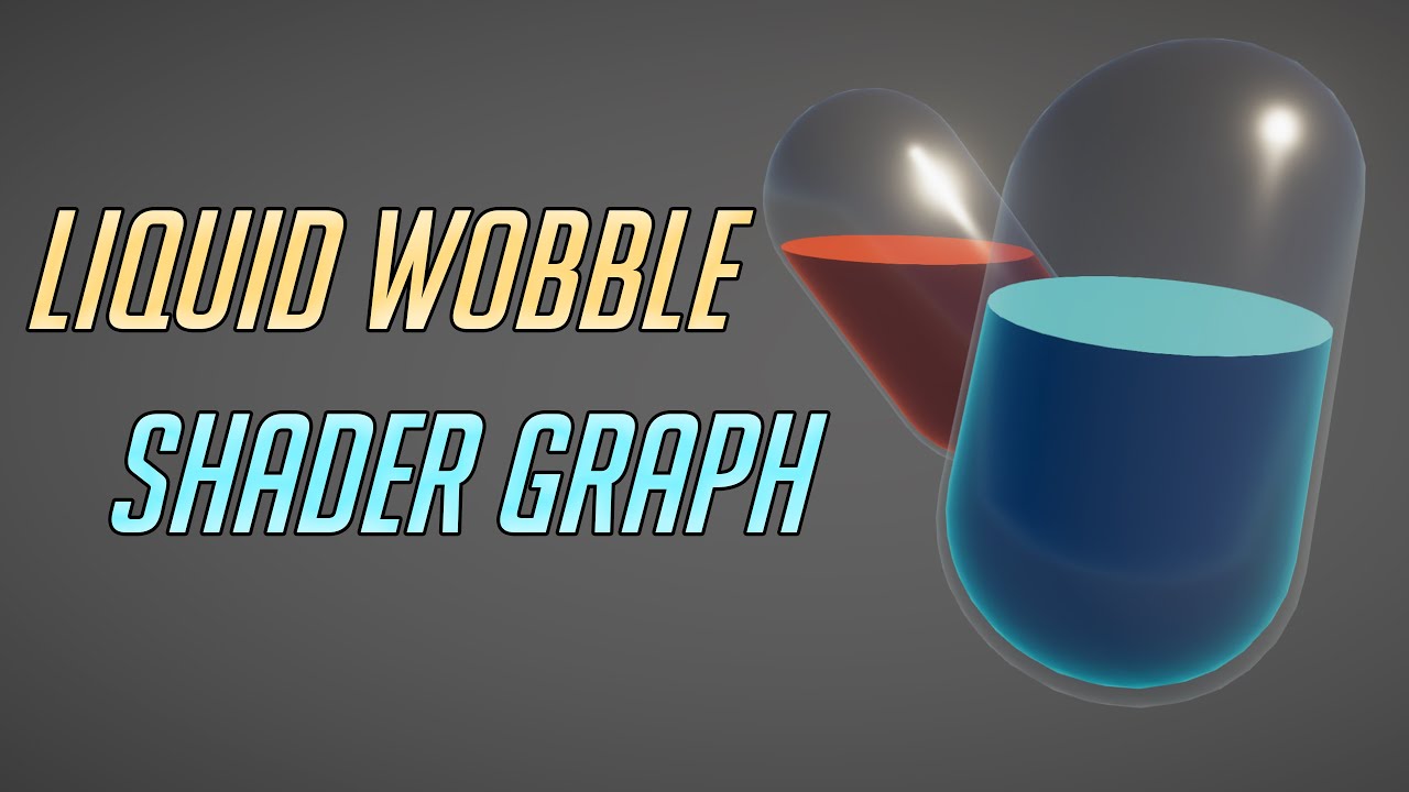
In this video we will show you how to create a Potion Liquid Wobble Shader Graph using Unity 2020.3 URP.
Download project files (Patrons Only): https://www.patreon.com/BinaryLunar
00:00 Intro
01:00 Create new unity URP project
02:00 Creating Glass Material
03:10 Creating Liquid Wobble Shader Graph
03:35 Creating the fill nodes
05:50 Coloring the...
I have a some quads that overlap on the same plane. They're z-fighting so I thought I could incrementally increase the shader's Offset values? Can I access that value from a script? Does that sound sensible?
Or if I can change it, will it change it everywehre
Just offset the transform.position by .001 increments in the transform in the direction orthogonal to the plane. If that works for you. Otherwise, you'll need to pass in the offset and/or calculate one in the shader, and in either case you'll need a custom shader.
@meager pelican Thanks, I'll try offsetting them first and see how long it takes for them to get an unreasonable distance away from the wall. I tried 'ZTest Off' and that almost works (I don't care which order they go above each other for a minute), but TextMeshPro means I'd have the dig around in that shader too
standard shader zfighting

ztest off

If anyone else is curious, I ate my own theoretical dog food, and did a compiler output test of the SG remap vs the a hand-coded URP frag() math, just because I was curious as to the real-world results.
Hand coded...is 3 instructions (due to the need to have a half4 returned with alpha 1.
dcl_input_ps linear v1.xyz
dcl_output o0.xyzw
0: mad o0.xyz, v1.xyzx, l(0.500000, 0.500000, 0.500000, 0.000000), l(0.500000, 0.500000, 0.500000, 0.000000)
1: mov o0.w, l(1.000000)
2: ret ```

the Shader Graph remap node produces not-bad code, but larger:
```ps_4_0
dcl_input_ps linear v1.xyz
dcl_output o0.xyzw
dcl_temps 1
0: dp3 r0.x, v1.xyzx, v1.xyzx
1: sqrt r0.x, r0.x
2: div r0.x, l(1.000000, 1.000000, 1.000000, 1.000000), r0.x
3: mad r0.xyz, r0.xxxx, v1.xyzx, l(1.000000, 1.000000, 1.000000, 0.000000)
4: mul o0.xyz, r0.xyzx, l(0.500000, 0.500000, 0.500000, 0.000000)
5: mov o0.w, l(1.000000)
6: ret ```

and a basic "just do the math in Shader Graph" (Normal-->Multiply-->Add--> to _Base Color output) produces:
```ps_4_0
dcl_input_ps linear v1.xyz
dcl_output o0.xyzw
dcl_temps 1
0: dp3 r0.x, v1.xyzx, v1.xyzx
1: sqrt r0.x, r0.x
2: div r0.x, l(1.000000, 1.000000, 1.000000, 1.000000), r0.x
3: mul r0.xyz, r0.xxxx, v1.xyzx
4: mad o0.xyz, r0.xyzx, l(0.500000, 0.500000, 0.500000, 0.000000), l(0.500000, 0.500000, 0.500000, 0.000000)
5: mov o0.w, l(1.000000)
6: ret ```

All above are frag shader portions.
Looks like the math-version in SG is about the same as the Remap version, so the optimizer fixed it up, figured out the math, and the end result isn't identical, but it's similar.  IDK enough about IL to tell the cycle cost/speed of it all, probably really close.  And some of this might be SG overhead that's a few instructions that are just "standard" for SG.

The by-hand version wins out over both though.
If I did all that correctly.^
hey, how do i have a different a different renderer on a different camera in urp?
i want SSAO on one camera but not on another
Create two different Forward Renderers, assign each to the URP Asset. The Camera then has a Renderer field where they will be listed, can switch between them there.
Has anyone come across a shader not compiling in the editor but also not giving an error code? When I save my shader in Visual Studio and move back to the Unity editor it flashes the color I would expect from the shader and then immediately turns white as though it can't compile. But there is no error code given so I don't know where to fix my shader code
Captain, shaders that can't compile turn pink...
Must have been thinking of something else then. Well at least now I have a different problem
do you guys ever wanna do something but dont even know where to start? google is giving me nothing
i wanna have a scan transition kinda, between two materials or gameobjects
like this maybe

where it scans down to transition between the circle and square
i cant even find anyone else attempting this on google
Sounds cool. you want to do this in a shader?
- Default layer 1, everything that isn't impacted by the effect....to background render texture with main camera.
- Layer 2 "blue circles" layer....with camera to render texture.
- Layer 3, "Black boxes" layer....with camera to render texture.
- Post processing shader that has some "line" equation and a wipe effect that either overlays texture from #2 or from #3 over top and blits the results of the 3-combined textures to the destination/output.
im working on a different effect right now with a hologram thing and a toggle
https://www.youtube.com/watch?v=cWpFZbjtSQg
The section about slicing might help, but I don't think it's what you want. I would just listen to CarpeFunSoftware

Experimenting with portals, for science.
The project is available here: https://github.com/SebLague/Portals/tree/master
If you'd like to get early access to new projects, or simply want to support me in creating more videos, please visit https://www.patreon.com/SebastianLague
Resources I used:
http://tomhulton.blogspot.com/2015/08/portal-rende...

thats the project i actually built this project off of lmao
i have that shader in my assets but it doesnt work in urp
i tried to recreate it in shader graph but i couldnt get it to work
Uh, well lucky coincidence I guess
yeah
That's the first thing I thought of when I saw your graph 😛
How might I have it so that the normals are only able to be seen if the directional light is being applied to it? I don't like the way the water looks when there's not direct light on it...

I'm pretty sure my lighting code is pretty terrible, so I might need to go back and rework some of it
i made this, it kinda works
Make it turn from a cube to a circle, I want to see that
I think it looks pretty decent
no
bruh

So, idk if this would be possible, but do you think you could add like a diffuse map on the outside so it doesn't look so blocky when you transition?
I don't think diffuse map is the right word
falloff map might be the right word
So, you want your shader that transitions as well as the other shader, right?
Can you combine the two shaders?
i could try
That might be hard. Another thing you could maybe do is make the outline of the portals their own separate object?
That way they can have their own material
Sorry I feel like I'm not helping all that much
im just trying to merge the shaders rn
Make sure you have a backup of your other shaders. You don't want to create a new one that doesn't work and not have the old ones

I believe what that's doing is getting your view distance from the portal and changing the color based on that
he did
i dunno how id do that in shader graphs tho
Sorry I don't use shader graph
my shader is entirely based on the alpha clip threshold and alpha so it should be able to work independently of all of that stuff
I know nothing about shader graph unfortunately. I write all my code .-.
Weird question... if anyone have an idea go ahead...
In my code I initiate 3 colors
        colorBridge = GetHexColor(coordBridge, d, colorBridge_Normal);
        colorCorner = GetHexColor(coordCorner, d, colorCorner_Normal);
And to keep thing simple I assign them that way
o.Albedo = colorBridge;
It work well visually, but if I use ColorHex, I get about 2x the FPS than if I use colorBridge or colorCorner
Any idea?
You said you wanted a wipe effect.... with several objects....
@light epoch that's different than vanishing/fading in/out of two objects placed in the same location. It's a wipe.
You have to decide on what you want.
anything smooth, i wanted a wipe ideally but i settled for a different effect
@crisp ridgeAre you talking about shaders?
thoughts?
Yes...
@light epoch it's certainly smoother, but I thought you were going to with the effect you just made?
that is the effect i just made
The transparent kinda glitchy one?
@meager pelican Full simplified code, I remove everything else
{
    float2 positionWS = d.worldSpacePosition.xz;
    ComputeHexData(positionWS);

    float3 colorHex =  GetHexColor(coordHex, d, colorHex_Normal);
    float3 colorBridge = GetHexColor(coordBridge, d, colorBridge_Normal);
    float3 colorCorner = GetHexColor(coordCorner, d, colorCorner_Normal);

    o.Albedo = coordHex; // performant
    o.Albedo = colorBridge;// performant
}```
Other variable are define as Globalthis one
Yeah it just happened so fast I couldn't really see it
i could slow it down 1 sec
yeah do that, all that work would go to waste if you don't
Oh also, you need to make the scaleup smoother, I think you did it by hand which is why it looked weird, but it was pretty choppy
its not growing its moving closer to the camera
OK, I see what you're doing.
And you want to test performance of colors? Should be the same. They all get assigned to floats, red, green, blue. Assuming the color calc is the same for all. IDK what that's all about.
So...since you're only assigning one of them, comment the others out. Test them one at a time isolated, not with all three in the code.
It may be performance, or it may be the way the optimizer is dumping your unused code.
wait really?
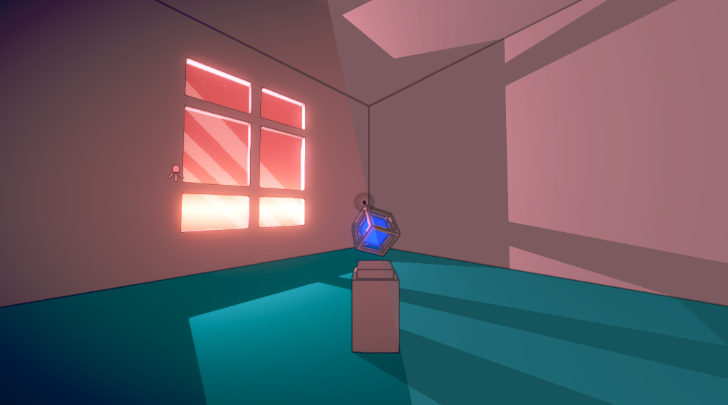
wait hang on. Explain the game to me pls
cant turn ur head, u have to use the mirror to turn the right way and go through puzzles
theres a normal world and mirrored world kinda
That sounds really cool
So when you choose you can walk through the mirror?
Or you can put the mirror through yourself?
Ah okay, and do you get another mirror once you walk through?
That sounds like a really cool concept
u use the same mirror but just move it
u can see how the text is affected
by the mirror movements
That looks really cool. As far as a game design perspective, it looks extremely challenging. You're going to have to make a really good tutorial level if you want your players to be able to solve puzzles
yeah i know
im taking it really slowly
before i introduce the concept of like
differences between the normal and mirrored world
level design is by far the hardest part of this all
which is why im working on polish before i even get to that point
Yeah, just from that first little "turn around" part it kinda blew my mind
lmao
i got the idea to make this when i was
maybe
12 years old
nah more like 10 or 11
and i had no idea how to even approach it
Was that a long time ago?
Okay, so a decent amount of time
Well it's cool that you're approaching something you never thought possible
Hey guys I have a question about creating material and stuff, is that the right place ?
i approached it in unreal engine but it just didnt have the capabilities i needed
Flaze it probably is
i couldnt use an oblique clip plane so it was kinda wonky
well not with blueprints
and i wasnt gonna attempt c++
c++ isn't so bad
I'm having this problem where my material is bugged

The chess board?
yes
Doesn't look like it's bugged, it just looks like it's wrapped around the board in the wrong way
I could be wrong though, I only see that one picture


Can you take a short video?
yes
From what I see in the pictures it looks like "Cull Front" is enabled somewhere
It looks like the shader isn't rendering the front of the object.
Ah
Let me see your settings for your material
What material are you using? Custom shader?
I basically imported a fbx, and a png
What shader. What material?

What shader is it using?
unlit/texture
That's Unlit-Normal, basically.
Check the texture import settings.

ok
And the FBX could have issues with UV mapping.
Does anyone know offhand what precisely the nonlinear function is that unity's Depth/Zbuffer value is?
I am trying to write out a depth from a raymarch compute shader which I can then use with eg particles for proper occlusion. The nearest I've been able to get visually is this:
float a = (CameraMaximumDistance + CameraMinimumDistance) / (CameraMaximumDistance - CameraMinimumDistance);
float b = 2.0 * CameraMaximumDistance * CameraMinimumDistance / (CameraMaximumDistance - CameraMinimumDistance);

float ze = (dot(hit.position - ray.origin, CameraForwardVector) - CameraMinimumDistance);
float zn = a - b/ ze;
gl_depth = 1.0 - sqrt(zn);
And that sqrt() irritates me immensely. It is so close to looking correct that I'm sure no-one would actually notice, but I can't believe that's actually how the depth buffer is meant to be constructed!
Download 3d Chess model available in fbx, obj, unknown format.
That's this one

That's my png import settings
There's macros for encoding and decoding them. What pipeline?
@sonic berry Well, it looks like there's an intentional line going down one side, and the vertical edges are "striped".
And your import settings look OK to me.
Standard RP, compute shader multikernels doing the raymarching, with a final texture copy to a RenderTexture that's then blitted in a command buffer.
I really just want to know the nature of the non-linearity
That's when I import it without doing anything

When I select it in the pannel on the left, I get these settings

The NATURE of it? Oh. Seems like they wrote an article or two about it when the switched methodology. But basically it is encoding a high-precision float into a float2, and decoding it. And IIRC the depth calculation is nonlinear from the clip-space or NDC perspective to preserve precision. Let me see if I can find you something. But you should look into the include files or download shader source if you haven't already. There's things like DecodeDepth...macro or function.
And watch for blits, as they often don't copy depth buffers over.
Oh I have it working with my own material to do the depth buffer copy, it looks right, I just don't have any logical basis for the 1 - sqrt(zn) line that I tried in desperation!
I'll dig through the includes, cheers
@light epoch this probably isn't the place to ask the question, but how do you get the videos to show in discord without having to download them?
they show automatically
just send it like a file
Yeah that's what I do
send one
okay
One moment
For me it shows a download
does it for you?
Maybe it's the file type
its the file format
k lemme figure out how to change that
I see here that it is expected that the texture should go around the board, there is a clear line, so why isn't working! 😦

@light epoch
that works
looks good
This is a SWAG, but you could try changing it to "clamp" on the import settings instead of repeat.
what is a S W A G?
Silly Wild Azz Guess.
ah lmao
I figured it was something like that
Okay so this is kinda stupid, but it does look kinda cool. Should this be one of those "it's not a bug it's a feature" moments?
I like how your water/terrain is coming.

oh thx @meager pelican
i created a board myself.... but the texture is not working when clamped
How does he make it look like that, it's crazy

If you're using stock shaders it should work.
I payed 10 buck for this, i'm pissed
Sadly I'm too beginner to know what this is
Did you try the standard shader like @wary jackal suggested?
I will...
I like glow in the dark water. But that's me....
"Feature"
Yep. lol
I mean, I can get it to not do that but it's not as stylized and the normal maps look ugly
That's not bad, but what you're "missing" for water is reflections. But that gets even harder, and is often not done in "stylized water". Up to you. But at night it would reflect any light source or mood or whatever. Otherwise it is a black mirror, basically.
With waves or not.
Yeah, but I think ima focus on getting shadows and stuff
I would agree on that priority for that style if it was up to me.
I mean, reflections are expensive too.
"Sort of". I mean you need a logical "ray" to the point, and you need a reflection ray to the "source" for the reflection even if it is a map from a reflection probe. (Which have their own encoding).
The two things I want to do are get shadows working and making a skybox that fits the style
I would like to make a game eventually lmao
Oh jeez I don't even want to think about 3d modelling
You can scroll the normal map at different scales at different directions over each other
A step or smoothstep can make it look more stylized as well. And for reflections you could re-render the geometry at a lower resolution with a secondary camera and use that for planar reflections but not sure if that would work if you have a spherical planet.
@sonic berryYou're in the standard pipeline, right?
Let's make you a shader to show the UV mapping of the mesh. There's already debug-views for the surface normals that you could check. If you go to the scene view tab/screen, there's a drop-down box that has options for what you want to view and you'd look for one that shows "normals".
But there's probably isn't one for UV mapping.
If you want.
@sonic berryYou can also check the import settings on the FBX model....like recalc normals, and any other things if related to UV's.
@devout quarry yeah I actually am scrolling the normal map in opposite directions (I think i wasn't in play mode when I recorded), i'll have to figure out different directions. I'll have to look into what a step and smoothstep is, as for reflections, I like that idea, but for now I'd like to get shadows working first. Thanks!
I've been looking at coding a custom skybox, and I found this tutorial which seemed promising, but upon further reading it just says "copy and paste this code". It seems to get the results I want, but I don't really know how it works, and that is not what I want. Does anybody have a resource I can use to learn, or is willing to explain how it works?
Code the Shader Double click on your Shader file to open the monoDevelope window. Copy the following code into the Shader file and save it. Shader “Skybox/Horizon With Sun Skybox” { Pro…
why doesnt this alpha work?

im not too sure how this shader works, i added the alpha to it
this is the original

got it
i added Blend SrcAlpha OneMinusSrcAlpha in the subshader thing
nice I was just gonna say that
So I made this really trash "fog" shader, because I really had no idea what the heck I was doing. It "works" but it's pretty terrible. Any suggestions on making it look better?
The shader might be terrible, but it makes for a pretty cool "cut scene effect"
woah
(Gydhia is coming)
Did you found a solution for this ? I have the same issue 🤔
Hey ! I'm using some FX in my game, but it doesn't seem to work with URP, and the material appears pink (I tried to upgrade to URP)
The material works with a shader, may anyone could help me with the simple code below please ? :s
Is there something to change so it would work with URP ?
Shader "PolygonArsenal/PolyRimLightSolid"
 {
     Properties
     {
       _InnerColor ("Inner Color", Color) = (1.0, 1.0, 1.0, 1.0)
       _RimColor ("Rim Color", Color) = (0.26,0.19,0.16,0.0)
       _RimWidth ("Rim Width", Range(0.2,20.0)) = 3.0
       _RimGlow ("Rim Glow Multiplier", Range(0.0,9.0)) = 1.0
     }
     SubShader
     {
       Tags { "Queue" = "Transparent" "RenderType"="Transparent" }

       Cull Back
       Lighting Off
       Blend SrcAlpha OneMinusSrcAlpha

       CGPROGRAM
       #pragma surface surf Lambert

       struct Input
       {
           float3 viewDir;
       };

       float4 _InnerColor;
       float4 _RimColor;
       float _RimWidth;
       float _RimGlow;

       void surf (Input IN, inout SurfaceOutput o)
       {
           o.Albedo = _InnerColor.rgb;
           half rim = 1.0 - saturate(dot (normalize(IN.viewDir), o.Normal));
           o.Emission = _RimColor.rgb * _RimGlow * pow (rim, _RimWidth);
       }
       ENDCG
     }
     Fallback "Diffuse"
}```I'm using another material for some faces
the hole is not visible through mountains anymore ?
No, because there is another material on the moutain that the one on the ground
I don't see why this would solve the issue 🤔
One material can be pierce by the stencil buffer, the other not
Ok I see. It won't work in my case tough because I have to use the same material for the mountains 🤔
If I could find a way to make the stencil test to fail if the z difference is greater than a small number, it might work. The goal here is to not see the road trough the hill :

In this case, the road is a lot further away from the camera, if we compare it to the terrain, because it's on the other side of the hill, so the stencil test should fail because of that
@cinder forge You can use z-test and stencil at the same time....
@cerulean duneUse shader graph and re-write it.
Hey guys. Anyone managed to reconstruct the world position using the depth buffer with the Post Processing Stack V2 (Standard pipeline)?
I've found some samples over the internet, but so far, no one worked as expected
Ok, thx x)
You're better off telling us what's not working and showing your code. What's not working, how? What pipeline?
I take it you want us to supply some cut-and-paste solution? (That would be cool to have a code snippets library for unity, standard and SG).
You can pastebin the shader if standard pipeline.
@meager pelican I've tried so many solutions...lol
I'm rolling back the code to the one that "almost" worked
It worked in the scene-view
But not in the game-view
Try this. This is just a goolge (hope it wasn't one that didn't work already). He's doing it in a post-processing "blit"...He'd pass those matrices in each frame, basically builds a matrix to compute it from the depth given the current camera's matrices.
https://stackoverflow.com/questions/39935774/unity-shaderlab-transform-from-screen-space-to-world-space

Stack Overflow
I'm making a post-processing shader (in unity) that requires world-space coordinates. I have access to the depth information of a certain pixel, as well as the onscreen location of that pixel. How ...
That might suck though, on second look if he's using GL stuff.
Cyan has a post on it too:
https://www.cyanilux.com/tutorials/depth/#reconstruct-world-pos
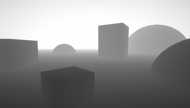
A big post explaining everything about Depth : Depth Buffer, Depth Texture / Scene Depth node, SV_Depth, Reconstructing World Position from Depth, etc.
@grand jolt
Gonna check it out
Hey i have a problem
i have texture rendered from a camera

can project it right

I assume you mean "can't"...
What are you trying to do? An inside dashed outline?
hmm
there is no alpha info on the texture bcs camera doesnt have alpha buffer i guess
i found a trick solution
just increasing the intensity of the color manually
but i would be glad if i know a clean solution
Thanks for that. Uhmmm that's not quite what I was asking though.
Do you want an outline shader, or do you specifically need this projection methodology to work for some strange reason?
I'm asking because that's not how you commonly do an outline, and further, you'll have to keep the two cameras and object locations in sync as you do the rendering of the first texture, or the top oval won't match the outline of the log (which already shows in your example...the outline is more curved on top than the other object).
well the dotted area comes from a custom polygon component
it is easy to level design that way
so i am focusing on taking the texture and projecting it
Is there a way I can specify max texture resolutions per scene? For example, having a high res texture on a model in a menu vs a lower-res version ingame.
I know this is often done through LODing, but I'm not sure if that is the best approach here
LOD usually has a much to do with the detail of the model's mesh as it does with the texture (MIP levels). The idea being to swap out lower resolution meshes at greater distances...to a point. You really only need about 2 or 3 models, triangles are relatively cheap.
So with MIPs the GPU automagically selects the MIP level according to the resolution it is rasterizing the object at during the rasterization stage. That said, in a shader, you can specific the MIP level directly if you wish.
In the end, I'd say it will probably be easier, if it works for you, to make sure you're using mipmaps or simply have two versions of the texture. But if you're using mipmapping, you should get lower res versions automatically. There's mip-level settings on the Tex2DLOD function if you want to override them in your custom shader.
https://www.youtube.com/watch?v=8OtOFN17jxM
If that's TMI, then just set the mip level bias in your shader by sampling at a different MIP level.
https://www.youtube.com/watch?v=2G0Sime3OH0

This video is part of an online course, Interactive 3D Graphics. Check out the course here: https://www.udacity.com/course/cs291.

✔️ Works in 2020.3 ➕ 2021.1
Mipmaps are scaled down versions of textures Unity generates which look and perform better when the texture shrinks on the screen. In this video, I wrap up this series on mipmaps by investigating how the renderer chooses which mip level to use and how you can influence this with SampleTexture2DLOD and mipmap biases. ...
There's also settings for the texture importer (might be hidden). And IDK how/if that impacts the UI either.
@meager pelican ok, so unity handles the mipmaps automatically. That was actually my next question, if manually setting these was actually necessary. thanks for the information!
Hi, I have an unlit shader in shadergraph withe a custom light function. I want to sample information from the ShadowMask for additional lights. I use GetAddionalLight function but don't know how to fill the shadowmak parameter.
I try the following code where lighmapUV is TEXCOORD1 but the result for the shadowmask is not correct
half4 shadowMask = SAMPLE_SHADOWMASK(lightmapUV); Light light = GetAdditionalLight(i, WorldPosition, shadowMask);
This tutorial might help, IDK what version you're on, and IDK if you're in URP or HDRP....
https://blog.unity.com/technology/custom-lighting-in-shader-graph-expanding-your-graphs-in-2019

They compute shadow information in there, there's sample code.
You'll probably need to add some keywords to the graph :
#pragma multi_compile _ LIGHTMAP_ON
#pragma multi_compile _ LIGHTMAP_SHADOW_MIXING
#pragma multi_compile _ SHADOWS_SHADOWMASK
May be able to specify them in a custom function, otherwise try adding them to the Blackboard as Boolean Keywords, make sure you set the reference not just the name.
Yes I already add the keywords but it look like I have a scale and an offset in the lightmap uv, because I can see the shadow but not in the correct place.
It looks like they have standard functions for that stuff (it's detailed in the tutorial).
Like (just browsing it)
   half4 clipPos = TransformWorldToHClip(WorldPos);
   half4 shadowCoord = ComputeScreenPos(clipPos);
#else
   half4 shadowCoord = TransformWorldToShadowCoord(WorldPos);
#endif
...```There's an include file you'll need.
The Lit.shader uses OUTPUT_LIGHTMAP_UV(input.lightmapUV, unity_LightmapST, output.lightmapUV); which applies the scaling/offset
@meager pelican I will try this !
I just want to say a big thanks because I start crating custom lighting shader in URP with your tutorial
hi there. anyone know how i would predict the depth at a certain pixel given its neighbor's normal and depth, assuming they are on the same face?
How does a color ramp texture work? I'm following this tutorial and it says to use a color ramp, but I don't really know what to do with that.
https://halisavakis.com/my-take-on-shaders-firewatch-multi-colored-fog/
You know what the gradient node is, right? So it's like that, but instead of smooth gradations, it's in "blocks"/"jumps".
So imagine a ramp of 5 white tones, with black, 3 intermediate values, and then white.
Often used in toon shading. It's just a lookup method. You can do it multiple directions (XY) too. He shows them at the bottom of the article.
So you might calculate, say, an N dot L simple lighting, but instead of just multiplying that directly, you'd take the 0-1 result and look up into your ramp texture to get the result.
Does anyone have glitch effect? I wanna this effect for my UI :)
@meager pelican uh, I don't use shader graph, so I don't have nodes. My problem came when I was trying to make my own, and I found this: https://rampgenerator.com/
How is that a texture?
hi everyone! anyone know a possible fix for the shadergraph preview working but the shader not showing anything in the scene view?
Chaotic Curiosity is it working in the game view?
I'm in a brand new HDRP project, if that helps
oh i'm totally guessing lol, I thought it's just one of those things
I actually don't use shader graph, so I don't really know. I just know that post processing effects only are applied to the game view
OK, forget i used the word "node". But you know what a gradient texture is....it's like that. But in bigger steps. He shows them at the bottom of the page.
Yeah I get that. I'm just confused how each pixel has its own alpha like he says
does it look like lighting is disabled
It's an RGBA texture, I would guess. IDK, i didn't digest the whole article because I didn't need to in order to answer your question.
Hm, I guess I didn't know that that was a thing
Yeah, 4 values for each pixel. If that's what he's doing.
Or he's looking up alpha from some grey scale texture and applying it to .a. Or whatever. It's all vectors and values.
it seems that the lighting is on!

found the button to press lol. thanks for the help anyways

"Always Refresh" needs to be on to get it to animate in scene view
Well, they don't produce a texture directly, that site gives you code. But it display a "texture" vertically.
So I'd do a screen grab of it, paste it into an editing tool, and then crop it all and turn it sideways and save it as a PNG or something in your unity assets directory.
Then you just do a uv lookup into it. With x as the 0-1 value, and say 0.5 as the y value.
Is there anyway to render outside of an object with a shader?
No, but you can change the size of the object, and then render bigger, and then squish stuff....so technically no, but in reality maybe. 😉
Or you use a post-process and render over top of the screen.
I had thought of moving the vertices, but I am not sure how to render the original shape first
What pipeline?
none if possible
Built-in, URP or HDRP?
Built in
Oh! you're in luck. Look at multi-pass shaders. You draw it normally for the first pass in your case to "render it first" and then draw your 2nd pass over top, but you use z-clipping or stencil to make sure you don't overwrite the first one.
Is this an outline or some such effect? Google for multi-pass outline shader or something.
Wow, thanks this might work, I am relatively new to unity shaders, I don't know much about the ins and outs.
I wish I new all the tricks. 😦
There's several challenges to outlines. We get a question on average every other day. And there's no one answer either.
I am not making an outline
Well, OK, but it's not an inline. (pun)
hehe
!unmute 467067465235431444
 Mateu#2340 was unmuted
The bot seems to have had a hiccup and didn't unmute you
Thanks
Is there a way to pas information between shader passes?
Yes I know but I did not manage to create the effect I want
Because they have an aversion to blue?
That or there's an error....
lmao
If you mean per-pixel, you can stuff it into another texture that you update in the frag on the first pass.
If you just need a bit, you can use stencil
What exactly do you mean?
Okay, I have yet another problem. my fog uses the camera's depth texture to work, but because the water is transparent, the fog basically goes right over it... Would I need to render the water on a different camera and then combine the two images to make this effect not happen?
https://www.youtube.com/watch?v=vTMEdHcKgM4 This video at 16:28 appears to have a similar problem
I got a bit tired of my simple heightmap-based planets and decided to experiment with generating them using the Marching Cubes algorithm instead, so that I could add a 'terraforming' ability for shaping the world with caves and tunnels and so on. I hope you enjoy!
If you'd like to get early access to the project files (they'll be made freely av...
Can you do what he did to fix it?
in my terrain shader, I have Stencil { Ref 1 Comp notequal } and in my road shader I have Stencil { Ref 1 Comp always Pass replace } and with this code the road can be seen through the mountain 🤔
That's what I was thinking, but he doesn't really explain how he did it very much, so I don't really know how
It seems like there is a public function in the camera component to render with a shader
not sure though
I wish I had access to the code for that video, but it's not available for a while :/
I am definitely no expert
Also, not only that but my water is transparent, so it can't even write to a depth texture as far as I'm aware
He did a different camera, and rendered the water to his own "depth texture" first.
You and the RubberDucky kinda both have the same problem, but yours is more-specific....you want to pass depth between passes, basically, and Sebastian did that with a separate pass with a depth-only write in an opaque pass. You don't have to render any colors or think about anything other than outputting the pixel depth. Maybe? he rendered terrain too, but maybe not. Like you say, he doesn't describe what he did.
Then, later, when you render the "real" scene, you can take the min() of the two values, the water-depth-texture, or the current-depth-texture, and do your fog calc.
But all that means you need to do a render pass of your water, probably with a named pass.
Is your fog a post process, or what?
fog is a post processing effect, yeah
It takes the camera's depth texture and does some fancy stuff to get fog
Right, but you need water depth before that. So you could render the water-depth after the water even. Or you could output to multiple render textures, and output a depth in one pass, even if you're in the transparent queue.
But IDK if that will work on all mobile or not.
idc if it'll work on mobile, I wasn't planning on releasing this to mobile (if I even release anything at all). So could I add another pass on the water shader that renders it opaque, store that depth texture information, combine it with the camera's depth texture, and then use that for my post processing effect?
Of course, most of the time my water is opaque anyway, so the easiest solution would be to just get rid of transparency altogether... but that feels kinda cheap nevermind it needs to be transparent for one of my effects to work