#archived-shaders
1 messages · Page 205 of 1
Nice. I've only been doing shaders for like a week, so a lot of stuff is going over my head. Right now my end goal is to make a okay-ish custom looking toon shader so I can make a small game
Thanks for your help
🙂
I'm having a pretty simple problem where I have a sprite shader that I'm trying to make unlit (so it's not affected by any light) but when I set the material to sprite unlit, it just doesn't show up no matter the base color or the alpha.


remove the alpha line, and just plug a 1 into it for now. Does it show up?

OK, that's weird. The only other diff I see is that the top (working) one has a tangent-space normal in it. Which, since it is unlit, I don't see where you'd need one.
Yeah
I hate to ask, but are you feeding it a sprite as input?
Show me.
blackboard, graph.
A sprite is a mesh.
Either a quad or it is a computed mesh around the sprite shape.


Create a sprite object in the editor.
It's a game object, has a renderer. And maybe a quad or maybe something else. But it is a mesh.
I assume you have that or the lit wouldn't have worked.
It's a plane using the material made from the shader graph
Maybe I should use an actual sprite?
So use a sprite renderer rather than a mesh renderer?
Ok I'll try that thanks
Unity - Creating Sprites - Sprites are simple 2D objects that have graphical images (called textures) on them. Unity uses sprites by default when the engine is in 2D mode. When viewed in
#pragma exclude_renderers d3d11``` Uhh, this appeared randomly?Well, show your v2f struct. Delete the pragma.
I think I fixed it, I just defined a variable in the wrong place
So I've made an outline shader for pickups that should outline the object nearest to player, problem is that when I toggle it on EVERY object with that material and shader get its outline activated, how can I solve that?
One solution I tought (even if not that clean) was to create an instance of that shader for each object by creating a meterial of every different pickup, the problem is that I generate them via runtime so I cant do that
Hi, I have generated lightmap uv2 for models, how can I use the uv2 in vertex shader ?
like this :

Hey I'm trying to get normalized y coordinates on an object that only go from 0 to 1 (or -1 to 1 just remap) but trying to normalize the object position just makes it so the magnitude is 1 and gets a weird y position. Is there a way I could get the top of the object and the bottom of the object or like the lowest and highest vertice and use those? How would I access that?
You'd have to pass the remap info the material I believe
I don't think object dimensions are passed to shaders
Hi, I made a water shader but I do not know how to use it in the new project. Please help me.
@grand jolt You made it, did you?
@misty flameYou could put an AABB in an instanced shader's instance-data. Or just min/max Y if that's all you need. But you'd have to have it passed into the shader, and depending on the pipeline that isn't always easy...I'm still unsure about URP and instancing data.
Another way is to do instancing manually. Assign each object an index in, say, uv4 or something, and then pass the per-instance data in a CBUFFER. Which is basically what the engine is supposed to do anyway. But SRP batching and instancing was a problem last I knew, at least with Shader Graph. So it all depends.
@keen patioThat is how you do it. What is the question?
@silk skySee answer to @misty flameabove. You want instance-specific data. As far as how....depends on the pipeline, but you should be able to make per-object material instances in C# if you want to.
By instance-specific data, do you mean a way to simulate having multiple materials with the same shader and different inputs but with only one material?
Another way to phrase that is: Each object has it's own "special data". So for colors, one is blue, one red, one yellow, one gold. But there's only one material and one shader.
So somehow you have to have object 0 look up theColor[0], object 1 look up theColor[1], ... and the shader uses that for color. Somehow if you need unique stuff per instance, that's what you have to pass. The thing is, if you don't or can't use Unity's instancing mechanism, you have to stuff some data into every damn vertext.
What you really want is the instance-id for the current mesh. But that's why it's mutually-exclusive with batching, which combines meshes into one big mesh. So you see stats in the profiler (maybe stats) window separately for instancing and batching.
Does anyone know of a custom function for shader graph to sample the motion vectors texture? (HDRP)
If you made it, you must know how to use it. They go hand in hand.
I just solved by making 2 different material (OutlineOff and OutlineOn) and then I swap them on the different objects
That works. 🙂
Surely better performance-wise than instantiating a material for each obj
Just build it here

Just build it here
Yeah I only needed one object to have the shader so I just passed in some values and I'm good but the per instance stuff looks useful so I'll look at that thanks
You'd definitely avoid that. But SRP batches by shader not material, so it depends on # of instances how bad it is. And what per-instance data you need.
Your question is making less and less sense. I don't know what you're actually asking.
Oh i tought the batcher was by mat and no shader, cool
It is by mat in Standard pipeline. But by shader in SRP.
How to extract in 3d project
Extract what?
How to use it in another project
If you're written a water shader using Shader Graph in URP, you cannot use it in the built-in pipeline. SG is currently not compatible.
You would need to rewrite it using built-in shader code (ShaderLab & CGPROGRAM stuff)
https://forum.unity.com/threads/motion-vectors.815385/#post-6153094 I tried to recreate what this user created to sample the motion vectors, but I get this error in Shader Graph:

Thanks
SG v10 needs to use #ifdef SHADERGRAPH_PREVIEW, not #if, that's probably what that error is about
That resolved it! Thank you!
Why is a ":" used when you're grabbing mesh data in a shader? Like float4 vertex : POSITION;
Those are "semantics". They bind hardware things the GPU knows, to variable names you use.
Like the GPU requires that POSITION because it's part of its rasterization routines.
Oh that makes sense thanks
so the : is just to make it stand out against a normal instantiation
Well, it's a declaration, but yeah. It's the syntax for doing such per the language rules.
It's "tying them together".
This confused the heck out of me for a long time too.
https://docs.microsoft.com/en-us/windows/win32/direct3dhlsl/dx-graphics-hlsl-semantics
A semantic is a string attached to a shader input or output that conveys information about the intended use of a parameter.
Using Append buffers whats a good approach if i have an unknown count? Do these resize?
Well, you should have a known max count FOR THE FRAME. But append buffers are for adding dynamically. So you can add 0 to MAX items to it. That's what the append does.
Output buffer that appears as a stream the shader may append to. Only structured buffers can take T types that are structures.

This topic contains a list of resources that Direct3D 11 supports (specifically feature level 11 or 9.x hardware).
hey, how can i change the position of a sprite(flipbook), relativ to another texture( inside the shader) besides tiling and ofset? cheers
@meager pelican so the same limits as any list given you don't know the size allocation.
for example: walking animation
anyone know how to filter a cubemap? I'm using it to calculate heights in a compute shader but when getting really up close everything get's pretty blocky. I can't find almost anything on google.


It's mapped on a standard quadsphere
like LOD?
That sounds right. I tried texCUBElod but maybe I'm using it wrong. 1 sec let me try to recount my issue with that
Right so when I do that, I get a strange error:
TextureCube<float> mars;
samplerCUBE sampler_mars;

float GetNoise(float x, float y, float z) {
    return texCUBElod(sampler_mars, float4(float3(x,y,z), 2));
}
Error:
Compute shader (Mars): Property (sampler_mars) at kernel index (0) is not set
As far as I understand, I only need to set "mars" and "sampler_mars" will automatically be set?
computeShaderModule.shader.SetTexture(kernelID, "mars", texture);
That's what happens when I use texCUBElod.
Huh. And kernelID = 0?
As far as I'm aware yeah, it should be:
#pragma kernel ComputePositions

[numthreads(256, 1, 1)] void ComputePositions(uint3 id
                                              : SV_DispatchThreadID) {
    dataBuffer[id.x] *= scale;
    dataBuffer[id.x] = rotate_vector(rotation, dataBuffer[id.x]);

    dataBuffer[id.x] += trPosition;
    dataBuffer[id.x] = normalize(dataBuffer[id.x]);
    float height = GetNoise(dataBuffer[id.x].x, dataBuffer[id.x].y, dataBuffer[id.x].z);
    dataBuffer[id.x] *= radius;
    dataBuffer[id.x] -= trPosition;

    dataBuffer[id.x] *= (noiseDiv + height) / noiseDiv;
}
var kernelID = computeShaderModule.shader.FindKernel("ComputePositions");
and it does return 0 when debugging.
The input positions are just object space vertex positions
You have to set for each kernel ID properties right before you dispatch.
But I'm not seeing the error.
You have the right idea, IMO.
Anyway, LOD 2 will be blockier than LOD 0
SOLVED
IIRC there's a macro/function for sampling cube maps. They're usually encoded too.
Spherical harmonics stuff.
Ok I will see what else I can find. Thank you for your help
That's what I gather too. 🙂 But since you know the stride, and since you MAY be able to calc a per-frame count, or at least pass in a MAX value, you could maybe handle limits. 🙂
@meager pelican thanks. I've set an estimated max for now. This is my first go at compute shaders, my only concern at the moment is the speed of copying buffered data to the gpu to be processed but it might just be fine, i heard downloading tends to be a bottleneck.
Yeah, it's designed for up, mostly. But with modern GPU's and GPGPU (like compute shaders) it's gotten better, as I understand it.
GeForce GTX 1050 Ti. Not amazing but should work for what I'm doing.
https://github.com/Unity-Technologies/Graphics/blob/master/com.unity.render-pipelines.core/ShaderLibrary/Common.hlsl#L925
It looks like texCUBElod is just using SampleLevel under the hood, which is what I was using before with the blockiness. I don't have any mipmaps, that's why I need to figure out how to filter the cubemap; any suggestions?
Like is there such a thing as bi-cubic filtering but for cubemaps?
Figured it out 🙂
Converted the coordinates to equirectangular texture coordinates, calculated a bicubic filter and converted the uv's back to normal coordinates in order to get the samples for the filter.
Not seeing any stretching on poles so far at least.
Usage:
float SampleCube(TextureCube<float> heightmap, sampler texSampler, float3 pos)
{
  return SampleBicubicCube(heightmap, texSampler, pos);
}
Nice and smooth 😎


Why UV channel's color is colorful like this?

UV mapped to RG
Im new.I dont know.So unity assgins a default color to UV?
Like this?

I'm so confused .Where should I start with ro learn shader?
It's just a representation so you can see what is in the UV channel. It's all just numbers, so UV becomes RG (red and green) as they're standard colours
It really helps if you start thinking of colors as just numbers

U V, whatever you want to call them
your graph was correct (except for the y axis label being flipped)
run the value from G into a Preview node to see it as greyscale
and again, black is 0, white is 1

Yup 🙂
Btw,what good toturial should I start with?
Standard shader scripting,Shader Gragh
I dont know where to start with...
Hey, I have big problem about performance with nature tree, speedtree8
All keywords are disabled, instancing is enabled
I see many normal if/else branches, can it be the problem?
Do you know an efficient tree shader for android devices?
Mobile in General:
Tile based rendering and lots of trees will be a problem. Because trees (well, leaves) use cutouts. And when you have any form of transparency, including alpha cutout/threshold, it disables the tile optimization routines. The GPU is forced to "blend" the entire quad's area and not reject pixels that are occluded.
As I understand it.
With tile-based hardware, it accumulates all draws into the "tile" in a stack...think of it as drawing all meshes in all tiles (small sub-divisions of the screen) and clipping the pixels that are out of bounds quickly so only the relevant ones are processed much for any given tile. It also does hidden-surface removal. BUT...it cannot reject the "behind" pixels if there's any alpha-usage. AKA transparents or alpha-cutout.
Then there's the issue of tile-memory vs system memory. Tile-based mobile GPU's try to keep info in tile-memory and not have to move it to the "main memory" which is shared with the CPU (because it's mobile, and mobile chips have limited on-board memory). And that operation is slow. Whereas desktop GPU's have gigs of local on-board memory to play with as well as closer-to-core caches.
Speed Tree
So ST uses LOD models and multiple materials. This complicates issues somewhat, but it's a good idea in general. The thing is, that per Unity's brief documentation on the topic, you should avoid using trees with lots of LOD on mobile, since the multi-material and multiple LOD issues cause more draw-calls than you'd like.
performance.```
https://docs.unity3d.com/Manual/SpeedTree.html
See also:
https://docs.unity3d.com/Manual/class-Tree.html
Where you might be able to edit the tree to something simpler that would work better in your use case.

Otherwise, just use billboarded trees that you do yourself, or search the asset store for "mobile trees".Yes, it is cutout and I know it can be problem in low-end devices,perfect
Efficient tree shaders do not use cutout and instead employ blending?
@toxic flume you dont need LOD on mobile devices, since they have a small GPU, you cant implement HD materials on big maps anyway. So youre better of using basic oclusion culling and simple shaders for your game. vfx graph is also not supported, so you have to be creative when it comes to mobile, but theres one big plus point: THEY HAVE SMALL SCREEN 😉 😉
It does not work
//SpeedTreeCommon.cginc

 OUT.Alpha = color.a * IN.color.a;
 //clip(OUT.Alpha - 0.3333);
    OUT.Alpha = step(0.3333,OUT.Alpha);
I replace clip with the line above! even when .Alpha=0
  Tags
        {
            "Queue"="Transparent"
            "IgnoreProjector"="True"
            "RenderType"="Transparent"
            "DisableBatching"="LODFading"
        }
        LOD 200
        Cull [_TwoSided]
        ZWrite Off
        ZTest Always
        Blend SrcAlpha OneMinusSrcAlpha
Blending has nearly the same problems. I see that "solution" all the time, but blending ALSO disables optimizations due to the need to calculate the "behind" pixel that is being blended in.
The best solution on mobile is to not use transparency-related things at all, including alpha-cutouts.
Alas, that requires you to use opaque meshes with leaf-shapes for everything, but it might be faster.
I should use trees and can not remove them!
I use occlusion trees and a bunch of optimization but have problems in that tree shader
Basically what the GPU does is...it "knows" the type of shader. And if it "sees" alpha clip/discard instructions OR if it sees any transparency blending, it disables tile optimizations. Which sucks.
So switching alpha-clip for blend of 0 alpha isn't necessarily a solution. May depend on hardware, aka YMMV.
Don't use alpha or clip/discard. Find another way with meshes.
I'm far from an expert on mobile, though. Maybe others have thoughts.
OK, thanks
In general you'll trade having more opaque triangles for reducing alpha stuff.
And for speed tree specifically, try the editor from the link above and simplify everything. Fewer materials, low poly, opaque as possible. Or see asset store for other options.
@toxic flume
can i only have one rendertexture in use with shadergraph?
For inputs ? You can assign a rendertexture to each texture input of your graph, until you reach memory limits I guess
What is the difference between #ifdef and #if defined()?
#ifdef is short for #if defined(), but the latter allows you to check multiple defines too with and/or, e.g. #if defined(A) && defined(B)
Perfect, and we define them using #define
We can not change or add and remove them like keywords (shader feature and multi_compile), right?
Only can remove it by removing #define line
yeah i had some strange bug. i guess because of memory
Yes, and there's #undef to undefine
can i use a sprite animation via flipbook as a color source in vfx graph? (maybe wrong channel)
yeas thnk you, but i dont understand how/if i can/must use a shader for that, or simply just the image that is used to create a flipbook animation in shadergraph. and i just want to use the color of the flipbook. but i will watch the unity tutorial again!
I have a question
just ask
Sorry,My network was broken ;_;

Does the G in UV mean V of all the coordinates?
If I set it as T in the case,edge1 is set to 0.5 and edge2 is set to 0.6
Then are all the V value of coordinates between 0.5 and 0.6?
RGBA maps to XYZW , same values, just different way to name them
No, it remap to a [0-1] range. everything bellow 0.5 is 0, over 0.6 is 1, and in between it's interpolated
Ohhh. Got it!
If you want to restrict the values, you're searching for the clamp node
Thx. I see
Does shader graph still lack support for cull front?
Currently yes, though I think the "in-progress" Surface Options feature (https://portal.productboard.com/8ufdwj59ehtmsvxenjumxo82/c/259-urp-surface-options) might change that. Hopefully 2021.2?
In ShaderGraph, you will be able to change surface option settings in your shader and on materials for URP. These options include transparency and blend mode settings (eg: culling options).
Thx. This really hits me everytime I try to get back into shader graph. Its always like I could create this awesome library of raymarching shader functions I just need to start by setting culling to ... NOPE!
Good thing I can vote for this "feature" now
If you need a workaround for now, you could use a mesh that has the faces pre-flipped so you don't have to edit the generated SG code.
yeah thanks. sadly this gets a little annoying with toggleable outlines on entities for example
in the case of the raymarching volume this would be more feasible
Hello
I want to ask something
How to arrange a shader lab code? I mean I typed shader without any error but my () {} symbols are not at the same column
After arranging it worked
How to arrange the shader code neatly
?
Hi, question about compute shaders
Lets say in C# I want a function
that takes in a width and a height
and outputs an array, where each element is equal to x+y in a nested for loop
in this the size of the array is variable
and its also not returning a texture
so how would I do this?
What part of this is COmpute shader related?
I would like to do the function in a compute shader I rpobably should have specified haha
the thing that outputs the array is the compute shader?
Its obviously not actually width+height but its just an example
Yep
I dont wanna return a texture, but rather an array (or multiple) of variable sizes
I think there's basically two high-level options here
Either you used an array of predetermined length for the output
or you use an AppendBuffer
AppendBuffer? lemme look that up
Which is a ComputeBuffer with CombuteBufferType Append
In your shader code it would look like this: https://msdn.microsoft.com/en-us/library/windows/desktop/ff471448.aspx
Yeah I see, thanks a ton!
Seems like I can use this
Im trying to calculate triangles and uvs in a compute shader
so that I can make a mesh object in unity
so reutnring an array of triangles and uvs requires this
Hey guys. Any idea why I'm getting always black values regardless the UV I use to sample a shadowmap?
 UNITY_DECLARE_SHADOWMAP(_Shadowmap);
            float4 _Shadowmap_ST;

            RWTexture3D<float4> _VoxelVolumeLight : register(u2);

            v2f vert (appdata v)
            {
                v2f o;
                o.vertex = UnityObjectToClipPos(v.vertex);
                o.vertexId = v.vertexId;
                return o;
            }

            float4 frag(v2f i) : SV_Target
            {
                //Transforms the SV_VertexID into a 3D index
                uint3 id = GetVoxelCoordinates(i.vertexId);

                //Transforms the 3D index into world-coordinates
                float4 wpos = float4(id * _VoxelSize, 1.0);

                //Gets the shadow coordinate from a single-cascate light
                float3 shadowCoord = mul(unity_WorldToShadow[0], wpos).xyz;

                //Samples the shadow
                float shadow = UNITY_SAMPLE_SHADOW(_Shadowmap, shadowCoord);

                //Gets the final shadow result
                shadow = lerp(_LightShadowData.r, 1.0, shadow);

                //Stores into the voxel data
                _VoxelVolumeLight[id] = shadow;

                return 0.0;
            }
_Shadowmap, _VoxelVolumeLight and _VoxelSize are binded correctly
unity_WorldToShadow and _LightShadowData are also binded correctly
Quick question, how do I set a ComputeBufferType?
Computebuffers dont seem to have a function to do that
It's part of the constructor
OH so sorry
You cry and wait for VFX graph and Shader Graph to support compute buffers
i need to use compute shaders for a different reason, otherwise i would just use a pixel shader
well it depends on what you are trying to do with the results of your Compute Shader
i want to render it on the screeb
i tried following a github repo and copied everything but it doesnt work on my urp project'
but works in the repos project
same version of urp and everything
Draw a full screen quad or triangle and use a frag() shader to draw. Like post processing. If you can. IDK what you're doing.
URP/SRP/HDRP have post processing of some kind.
i have to run the shader multiple times per frame
can u do that with a pixel shader? @meager pelican
Well, if you want to draw it, say, 2 times....draw 2 quads and run it twice. Maybe a 3rd time to output something to the back buffer. IDK. Just trying to help. You may need at least DX11 though, if you need to write other textures in the pixel shader. IIRC. I should look it up, but....
You may have to use a color mask to stop output to the back buffer.
each pass needs the data from the previous one tho
That what the other texture would hold....
Some goggle searches are in order. But I think you can do it somehow.
Besides, I'd be surprised that URP cannot do it. I mean, there ought to be a way. I should research before shooting off my big fingers.
i dont really understand this but in shader toy i think you can use buffers to run a shader once, than run the other shader on that data, can u do the same in unity without compute shaders?
https://catlikecoding.com/unity/tutorials/basics/compute-shaders/
He's updated this just last month. It uses URP and has a compute shader. And he makes a custom function for use in Shader Graph. I frankly didn't read the whole thing, but thought you might be interested.
A Unity C# Basics tutorial about using a compute shader to make it possible to show a million moving cubes.
i think this is just for mesh stuff
Worth tossing him a buck or two if it helps you.
not for rendering an image
It's running a compute shader, from URP. From what I saw. That much you should be interested in.
yeah but i need it to render the image from a compute shader onto the screen
You need the RESULTS from the compute shader.
Full. Screen. Quad. Look up results, output color. Do a blit (see Graphics.Blit)
Or. Have the compute shader output the results directly to the output texture if you can.
Yo, so i have a weird issue rn with urp
I have this bit of code for a custom shader gui

It passes the current shader time to the material
where i then use it for some slight animation

When clicking e.g. the activate button, it sets a value of 17k rn
But the value at which stuff actually happens lies at 5.4k
aka the time inside the shader is around that value, as opposed to the one i got using Shader.GetGlobalVector
Any idea how that happens or how to combat it?
When testing in playmode the effect works perfectly fine
only edit mode hates me
Im trying to replicated the laser shown here: https://www.youtube.com/watch?v=mGd3nYXj1Oc&t=363s. But for some reason my laser texture shows up as solid white and not what it is. I can send in zoomed in images for certain parts of the shader


Unity Shader Graph - Laser Beam VFX Tutorial
In this Shader Graph tutorial we are going to see how to create a simple, but awesome, Laser Beam shader in Unity!
TPS Laser Tutorial: https://www.youtube.com/watch?v=YbWYc3W43EI&index=29&list=PLpPd_BKEUoYh40LeJXTgA6E53gCMPq3MX
Timeline:
1:10 - Laser Beam Shader
3:42 - Setup the Laser VFX
5:21 -...
The electricity texture im attempting to use, but shows up as solid white

The Alpha port on the master stack is greyed out, meaning it's unused and suggests that the surface mode is set to Opaque. You need to change it to Transparent (in Graph Inspector window, Graph Settings), or use alpha clipping.

can you convert a shader you made in blender to unity? or is it better to just make the shader from scratch Inside of unity?
There is no way to convert a shader from blender other than by hand
Hi, hope u all doin' good ! i got a strange problem with my water shader: My PBR graph shader for water is visible trough items, and i can't understand why, i don't even know if it's because of the shader or something else, but, here is the problem, and here is the pbr graph, so even just knowing if the problem is from my pbr or not would greatly help me


from scratch it is! thanks
The texture is probably set to Clamp in the texture import settings so beyond the 0-1 uv range it's the same as the edge of the texture. Change it to Repeat instead.
My guess would be that the material for that brick textured plane is transparent. Sorting transparent objects correctly can be difficult as it can't rely on the depth buffer and instead just sorts by distance to the GameObject origin. If they should always render in a particular order you can change the Render Queue on each material to force it. But in this case, if it doesn't need to be transparent, make it opaque instead and it should sort correctly.
Oh yeah, managing the sorting orders solved the problem ! as a new here I didn't even know it existed sorting orders for materials, thank's a lot for that saved time in my learning !
Hi all, is there an equivalent to _ScreenParams that takes into account RenderScale? I see _ScaledScreenParams but it's not clear to me what the shader graph equivalent is
Have you tried using it in a custom function? Searching the Graphics github suggests that URP does define and use _ScaledScreenParams in a few places.
_ScaledScreenParams works fine in my hlsl shader, I was wondering if there is a shader graph node equivalent for it
Don't think there's a node for it no
what is the standard way to expose a parameter like this via shader graph? I made a stub file which tries to just return the value of _ScaledScreenParams, but it complains of an undeclared variable.
Hmm, it seems to be declared in URP ShaderLibrary/Input.hlsl (which is included by Core.hlsl) so should always be declared afaik, assuming you aren't using HDRP. Maybe it doesn't exist for SG previews though, it's fairly common to have custom functions wrapped in an #ifdef. I'd try something like this (either in string mode, or wrapped in a function definition if using file mode)
Out = float4(0,0,0,0); // (or whatever value you want to give the preview)
#else
Out = _ScaledScreenParams;
#endif
Thanks @regal stag , that does it!
(I've been away and have to remember the quirks of URP...)
Does shader graph v11 have no master node? What is it replaced with?
@meager pelican I'm having some issues applying a normal map and I don't know why...
            {
                // i.normal = normalize(UnpackNormal(tex2D(_NormalMap, i.uv)));


                float3 lightDir = _WorldSpaceLightPos0;
                float3 viewDir = normalize(_WorldSpaceCameraPos - i.worldPos);
                float3 lightColor = _LightColor0.rgb;

                float3 albedo = tex2D(_MainTex, i.uv).rgb * _Tint.rgb;

                float3 specularTint = albedo * _Metallic;

                float oneMinusReflectivity = 1 - _Metallic;
                albedo = DiffuseAndSpecularFromMetallic(albedo, _Metallic, specularTint, oneMinusReflectivity);


                // * This is the Blinn reflection model:
                // float3 reflectionDir = reflect(-lightDir, i.normal);

                // * This is the Blinn-Phong reflection model:
                float3 halfVector = normalize(lightDir + viewDir);

                float4 diffuse = float4(albedo * lightColor * DotClamped(_WorldSpaceLightPos0, i.normal), 1);
                float4 specular = float4(lightColor * specularTint, 1);

                return pow(DotClamped(halfVector, i.normal), _Smoothness * 100) * specular + diffuse;

            }```
That's the code, and it works fine when I comment out the first line that unpacks the normal map, but when it's in there everything goes black.Or anyone if you're able to help me ^
Is there a document somewhere explaining which extra shader passes/replacements need to be handled integrate a shader (for a mesh in the scene) to work with the Unity PostProcessing Stack?
hello everyone, i have a question for stencil shader in Unity. The whitelines are using a shader with stencil. The Log and the Character writes value into the stencil buffer.
Currently I am applying the checkboard effect on the whiteline whenever the stencil reads a higher value in the buffer. However, I only want it to be done for specific type of object (in this case, the log).
Is it possible to do "the line is behind a Log object now, draw it using effect A. It is behind a Character object now, dont draw anything" ?
(im on built-in RP)

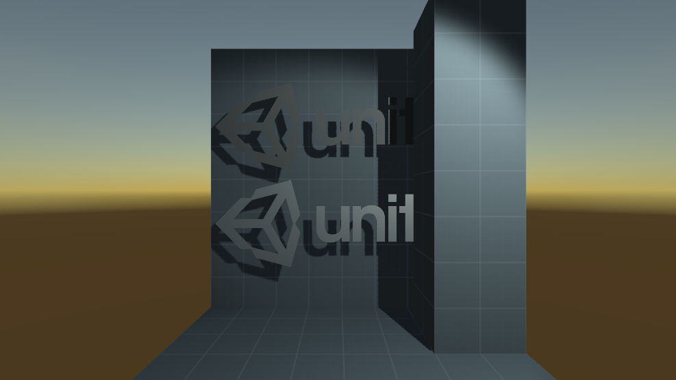
anyone know how to properly sample triplanar normals with shadergraph? in this image i'm expecting something more like the normal strength 0 section in terms of light strength, but instead the material looks like normal strength 1. the light is at a 45 degree angle so it should light both sides equally. im pretty sure my normal texture is fine, but i've included it just in case. and below is the graph where i sample the normal texture

anyone know how I would pass an array of 12 float2s from cs to hlsl?
I'm trying with a very basic compute shader read data, but it doesn't read me any values.
Basically
RWStructuredBuffer<float> output;

[numthreads(THREADS_PER_GROUP_X, THREADS_PER_GROUP_Y,1)]
void CSSimulate (uint3 thread_id : SV_DispatchThreadID, uint3 group_thread_id : SV_GroupThreadID)
{
    output[thread_id.y * 128 + thread_id.x] = -1.f;
}

-----
// init
cOutputBuffer = new ComputeBuffer(columns * rows, sizeof(float), ComputeBufferType.Structured, ComputeBufferMode.Dynamic);
temperatureComputeShader.SetBuffer(0, "output", cOutputBuffer);

// Dispatch (col = 128, rows = 128)
var groupsX = Mathf.CeilToInt(columns / (float)threadsPerGroupX);
var groupsY = Mathf.CeilToInt(rows / (float)threadsPerGroupY);
temperatureComputeShader.Dispatch(0, groupsX, groupsY, 1);

// Read
float[] testData = new float[columns * rows];
cOutputBuffer.GetData(testData, 0, 0, columns * rows);
Any idea what I'm doing wrong here?
(found it, need Immutable flag)
why cant i use a gradient for alpha clipping? the transition is not smooth like expected. it looks like the alpha channel can only deal with floored values (int). is that true?
so either its visible or not, but nothing in between?
are there even responders here? i only see questions....i thought this is the official unity server
i set the alpha threshold to 0, now its working
Alpha clipping just discards pixels if the alpha value is below the threshold. You can use a gradient for either input but the result will always be clipped or not clipped if it's an opaque shader. If you want partial transparency you need to use alpha blending (or a technique like dithering to fake it). In SG it's the Transparent surface mode & Blend mode settings.
You'd need to use a float array or pack it into a Vector4 array as Unity only allows arrays of those types. This article has some info about setting up arrays : https://www.alanzucconi.com/2016/10/24/arrays-shaders-unity-5-4/
In short, define float _Floats[24]; in hlsl. Set in C# using material.SetFloatArray("_Floats", array); (or Shader.SetGlobalFloatArray).
Alternatively I think you might be able to pack those floats into a Matrix4x4.
Understand, thanks!
But
shouldnt it be a 2d array
like [[float1,float2], [float1,float2]]
or should it be
float1,float2,float1,float2
and itll auto assign
@wary jackalWhat does your normal map look like? Is it the usual "redish-blueish" map?
P.S.
you shouldn't need to normalize it, nor do you have to store it back into the v2f struct. So:
half3 normal = UnpackNormal(tex2D(_BumpMap, i.uv));
Finally, output the normal as a color onto the object so you can debug it.
Unity doesn't allow sending in an array of 2 components from C#, only Floats or Vector4s. I think you need to change your array on both sides to float or float4/Vector4.
So wait
Should I do something like
instead of
float2 offsets[12]
float offsetsX[12]
float offsetsY[12]
It was replaced with the master stack in v10. https://www.cyanilux.com/tutorials/intro-to-shader-graph/#master-stack
and combine them?
You can pack them into a single array of 24 size. float _Offsets[24]
Yeah exactly and add 12 for the index
Depends how you organise the data but sure. I'd pack it like x,y,x,y,x,y.. and when you read it, use i and i+1
Yep
A little unsure how a mesh in the scene relates to full screen post processing. If it's for something based on depth though, the shader needs a ShadowCaster pass to appear in the depth texture.
Instead of testing for just a greater value you could have the player/log write different values and test against each one separately. e.g. Have the Player write 1, Log write 2. White line pass can test against "not equal 1", Checkerboard pass can test for "equal 2". I think that would work?
I'm not sure I understood that, but if you want to identify "behind log" vs "not behind log" you would only stencil the log. The stencil tells you if it's log-or-not.
Is your normal map imported as the "Normal map" mode? I assume it's meant to be the default bump map the colour, but it looks like some colourspace conversion stuff is being applied as it should be darker than that afaik.
weird
Nah, it's a good thing.
Lets you see what variables go into the vertex stage vs the fragment stage, rather than relying on behind-the-scenes magic.
How to convert SRP custom shaders to URP?
Thanks
lol
I assume by SRP you are referring to "standard" which is not the correct name. It's built-in pipeline. SRP is scriptable render pipeline which is a basis for URP and HDRP.
Any custom shaders need rewriting. URP Shader code is a bit different (and doesn't support surface shaders), it's usually easiest to recreate it in Shader Graph.
I thought srp is standard render pipeline which is in built pipeline bruh
Ok
It's a fairly common misconception
Then I got it right the first time. 😉 No worries.
Like Cyan says, the terminology often gets confused.
They have an "upgrade materials" routine, but it likely won't work, so you're back to "by hand".
Need a bit of shading advice

Im making procedural terrain and obviously now its pretty plasticky

I also have a noise map of the terrain
That I can make higher res
how would you all go about making the surfaces rouger using this texture?
I'd use two textures. One with a large offset, one with a smaller "grain" offset. And add.
And if they're not already, you should make sure they're tileable.
How can I make a shadergraph that changes texture based on the height of the vertex
On the y axis
By "changes texture" you mean what? Changes color, picks from different textures? Blends?
Got an example?
I'm trying to texture a terrain based on height, like the top of the mesh will have snow and the bottom will have grass
So basically I'd like it to blend between Textures2Ds based on height
Add as what?
Add the two results, that come from two textures. So you have your texture #1 that has "big changes" and your texture #2 for small grain stuff. And it's just a small offset. And you add the two.
So you might be adding a 2.359 Y offset and a 0.0419 offset and end up with the total, per pixel.
And you can make sliders to scale it (multiply it by some scalar value) for "intensity".
Or you can just use the one texture and sample it differently.
Im back
Cant really do this because
vertices is an issue
So this is what Id rather do, BUT
How would I convert this b&w image to a normal map? Know any resources?
I wouldn't
Alright, I'll find a few
I would just grab a normal map and tile it
the idea of "grainier" detail sounds good
Hmm it would work but I feel likd itd be unnatural
because my terrain isnt all rock
Yeah, thats a great idea
But
Blending between normal maps..
just seems like it wouldnt work but idk anything about normal maps
I'll check them out and see if organically blending would give me a good result
I'd start just tiling one
Yeah Ill start wiv that
and remember that it's mixing with the normals already there
one issue is rn the water is part of the mesh but Im changing that

Already makes a big differene
But I dont think its tiling
You have to transform the uv based on tiling/offset settings. There's a macro for it.
Google/research something like "TransformTex".
I would blend multiple together actually
You could have a bigish normal map + a super fine detailed one
But if you're doing vertex displacement, you MIGHT want to sample 3 points and calc an offset with epsilon and then calc a new-normal. Depends on what you're doing.
Then you don't need a normal map, but you have to incur the cost of 3 samples vs 1. Which if you do them ahead might not be too bad.
Oh will do nice
Sounds good
Well correct me if I'm wrong but like
Isnt that just what pre-generated normals are
for each tri it creates a normal facing outwards?
But then gain, I cant enable flat shading so maybe unity doesnt do that?
Well, they're pre-calced. But yes. But you're changing the polygon with vertex displacement and faking a normal with a normal-map read.
So you have your 1 vert displacement texture read, and your 1 normal texture read (and unpack). And for the cost of 1 extra texture read, you can dump the normal map and just calc the new normal that resulted from your vert offsets in the first place. So it's up to you. I'd actually benchmark both.
I see
Interesting, once I do more of this project and get to the optimiziation phase
I'll definetly try this approach
But do you want flat shading, like low poly stuff?

Nah, faked normals are better
Anyways, let me look up TransformTex
o.uv = TRANSFORM_TEX (v.texcoord, _MainTex);
https://docs.unity3d.com/2019.3/Documentation/Manual/ShaderTut2.html
oh god I know nothing about these types eof shaders haha
Alright, hopefully I can get it to work
shaders are black magic
yeah lmao
bruh i was doing noise in c sharp
and it was taking a bit for high res so I was like "ah well its a pretty complex function makes sense"
moved it to a compute shader
litereally instant
what is this black magic
4k texture in like a milisecond
makes more sense when you think about how many "cores" a gpu has
long as you have them doing the same instruction
baby threads
threads that don't like doing anyhting unless it is exactly what their sibling threads are doing
I have no clue how to start wiht this transform_tex thing lmao
bruh
never written a shader
can you just use shader graph?
Lemme see
pretty sure this kind of thing is very easily done in shadergraph
Texture reads are slow. Math is fast. But since you have an input texture dependency, you have it. That's the way it is.
The idea is to try and do some calcs or something after the texture read(s) that aren't dependent on the results and let the core not be stalled off as long, let it get some other work done. So do the read at the "top" and then do other non-dependent stuff, and then use the results.
maybe with a transform n ode
Yep, this exactly
so you can kick off a read
Useful for my use case atleast
Seeing as the entire point of my project is to generate textures and deform surfaces
and it'll speed it up
Sure. But if the "other things' depend on the results of the read, it has to wait for it.
I'm pretty sure shader compiler optimizer check for some of this, but I'd try to code it the smart way, in case you run into a dumb optimizer on some hardware.
i have no clue how to make shaders to such an extent
I cnat even find the shadergraph stuff in the creat menu

arent there supposed to be graph stuff
bruh
Can only use Shader Graph in URP or HDRP atm
ah damnit
do compute shaders work there?
later i may move the stuff voer
yes you can definitely use computer shaders with hdrp
I'm pretty sure you can use them with URP too
but you can't on android?
there's an asterisk
how could i make everything in the scene render with a shader? i have a simple psx vertex warble shader, do i need to apply it to every single material or is there a simpler way about this
if it's URP or HDRP I believe this can be done with renderer features or whatever they're called?
You can use a layer mask and it can override the material of the renderers in those layers
Not sure if you'd consider that "simple" or not
It's important to note that the URP override material stuff completely replaces the previous material. Textures and other properties won't carry over.
If you're in built-in RP, there's replacement shaders which can carry over textures/properties, assuming the new shader uses the same references, so that might be closer to what they want. https://docs.unity3d.com/Manual/SL-ShaderReplacement.html
anybody care to help cobble together a shader?
im trying to make a skybox like shader that displays a flat image in the background that works with an orthegraphic camera... much like this one:
https://gist.github.com/aras-p/3d8218ef5d96d5984019
^^ this works as expected. I was hoping to have it scroll as the camera moves, based on X and Y properties you can set on the material. this shader does just that when i set the rendertype to background:
^^ for all intents and purposes, this one works, but since im using an ortheographic camera, the edges have a "fisheye" effect. How can i mod it so its flat on the edges like the first shader?

Gist
Unity flat skybox picture shader. GitHub Gist: instantly share code, notes, and snippets.
Pastebin
Pastebin.com is the number one paste tool since 2002. Pastebin is a website where you can store text online for a set period of time.
Hey guys, im starting out with shaders and trying to make a good looking skybox shader, but there is like a seam going around the skybox.
Any way to get rid of it? I know i'm projecting a texture onto a sphere, but i will happily accept some overlap instead of this awful seam.
Thanks!

is yout texture set to clamp or repeat?
i had this problem in the past, i cant remember which is which but i remember that solved it for me

ahh.. ive never played with shader graph so im not sure, sorry
if youre using a texture it sould be on the import settings of the image itself
oh okay, thanks! if anyone finds a way to set it for a procedurally generated one i would love to know it!
The UVs are 3D for skyboxes so anything based on UV coords (like the Voronoi) is going to be stretched like that. You may be interested in the remapping of UV/Position coords discussed in this tutorial : https://medium.com/@jannik_boysen/procedural-skybox-shader-137f6b0cb77c
Thanks!
Hello, In most article i read people cull front face (instead of back) while drawing outlines with the help of stencil test.
Does culling front instead of back face have any advantage in this case ?
The common "inverted hull" style of outlines uses Cull Front as otherwise you'd just get a slightly inflated version of the mesh covering up the main pass.
If you're using it with some additional stencil operations though, it might not be required. e.g. The main pass can render to the stencil buffer, and the outline tests against it to prevent any outlines appearing over it. Using either cull option would work then and I doubt there's much difference which is used.
@meager pelican I think it might be messed up? The red is in the wrong place I think...
It also still goes black after I put the normal map in, so I think that's the problem. However, I have been able to use these normal maps before so idk what the problem is.

aah got it,
thanks
Is there a way to increase distortion at the edges of the screen in HDRP?

Feels like I'd have to plug something into the Distortion node
I assume you'd need the o.uv = ComputeScreenPos(o.vertex) to use the screen coord based on the clip space position, instead of the UVs stored in the skybox mesh.
thanks for the help ! unfortunately, this doesnt quite work in my game because objects can appear at different height, so at one situation the white line is covered by the log, at another situation the white line is actually "above" the log
in the end, i decided to just settle for also drawing the checkerboard for the player object
i was unaware of normal map import mode. i reimported the normal textures with that setting, but it still looks the same, unfortunately 😦
here's all of my import settings

Perhaps the texture values are stored differently than expected then. Maybe try the Default mode with and without the sRGB ticked and see if one of those looks correct?
still no luck 😦 i've also tried different normal spaces in the main stack + graph settings, but tangent is still the best so far
flipping the light around 180 degrees on the y axis "works", but i wish i didn't have to worry about that
how can you define a constant float
@acoustic bay does it kinda go black and look weird when you don't do that?
it's definitely something to do with colorspace conversion 🤔 i changed the project to Linear lighting and it works as expected, but i find Linear hard to work with for colors 😦
not sure i understand
in a shader? do you mean like a global constant?
yeah i
nvm, I'm having problems with normal maps and it kinda works when the lighting is in rotated


nothing that intense, but kinda
I think that's the correct syntax so should work afaik, I don't tend to use static consts though. Could use a compiler-time define instead, like #define PI (3.14159265)
What did you do?
that works thankyou
i reexported my normal map texture from Quixel with the normal channels set to Linear

I think ima check that out

wait what is quixel? lol
it's the tool i use to make my textures

Quixel
Simple and quick creation of anything you can imagine. Create photorealistic, tileable, materials in seconds with powerful mixing and painting.
i think it's possible to convert gamma to linear by doing
pow(sampledTexColor, 2.2)
or maybe it was 0.4545
I mean, that makes stuff look cool but it doesn't really work. I'm probably doing it wrong though
Can you share the shader code? (or graphs if SG)
yeah. sure
fixed4 frag (v2f i) : SV_Target
            {
                half3 normal = UnpackNormal(tex2D(_NormalMap, i.uv));

                float3 lightDir = _WorldSpaceLightPos0;
                float3 viewDir = normalize(_WorldSpaceCameraPos - i.worldPos);
                float3 lightColor = _LightColor0.rgb;

                float3 albedo = tex2D(_MainTex, i.uv).rgb * _Tint.rgb;

                float3 specularTint;
                float oneMinusReflectivity;
                albedo = DiffuseAndSpecularFromMetallic(albedo, _Metallic, specularTint, oneMinusReflectivity);


                // * This is the Blinn reflection model:
                // float3 reflectionDir = reflect(-lightDir, i.normal);

                // * This is the Blinn-Phong reflection model:
                float3 halfVector = normalize(lightDir + viewDir);

                float4 diffuse = float4(albedo * lightColor * DotClamped(_WorldSpaceLightPos0, normal), 1);
                float4 specular = float4(lightColor * specularTint, 1);

                return pow(DotClamped(halfVector, normal), _Smoothness * 1000) * specular + diffuse;

            }
            ENDCG
}```It's too long so I only sent the fragment shader
Okay, so the normal map will be in tangent space and needs to be transformed into world before it can be compared with the light direction. I think when using a surface shader it can handle all that automatically but if you want to use vert/frag you'll need to do it manually.
This tutorial goes over normal mapping & tangent space : https://catlikecoding.com/unity/tutorials/rendering/part-6/
There's also kinda an example on this page : https://docs.unity3d.com/Manual/SL-VertexFragmentShaderExamples.html (under Environment reflection with a normal map heading, if you Ctrl+F "bump" you'll find the code).
@wary jackal
@regal stag I have yet another question. In the code above, everything is darker than I feel like it should be. The line albedo = DiffuseAndSpecularFromMetallic(albedo, _Metallic, specularTint, oneMinusReflectivity); appears to do this, however, without it I can get some really bright reflections that don't look good. Any suggestions?
@wary jackal
        half diff = max (0, dot (s.Normal, lightDir));

        float nh = max (0, dot (s.Normal, h));
        float spec = pow (nh, 48.0);

        half4 c;
        c.rgb = (s.Albedo * _LightColor0.rgb * diff + _LightColor0.rgb * spec) * atten;
        c.a = s.Alpha;```
This is "similar to blinn-phong" per this set of examples:
https://docs.unity3d.com/Manual/SL-SurfaceShaderLightingExamples.html
You don't have to have a surface shader, that's just the example set. See about half way down for "LightingSimpleSpecular". That calc is a bit different than your current one. Something to try.P.S. "s" is their surface struct that has things like the normal and uv in it.
The params are
(SurfaceOutput s, half3 lightDir, half3 viewDir, half atten)
what do the letters stand for? like h, diff, nh, and c?
I assume diff is diffuse but idk the others
c is the resulting color.
diff is the diffuse light before specular (N dot L with a max 0 function).
nh is the normal half-vector.
spec is the specular amount/result.
So they take the lightcolor X the albedo color X the diffuse amount, and then add the light-color * the specular reflection amount to it and then attenuate the whole mess.
Yeah, I hate magic numbers like that.
I'll have to look it up in a real shader. Sec.
I just thought it would be a good test for you to try out and see if your calc is messed up, or your normal map is messed up.
What it looks like that 48 is...is they just hard-coded the specular value you'd set in the shader.
In another shader, this is for the mobile-bump-mapped-specular, they do it this way:
fixed spec = pow (nh, s.Specular*128) * s.Gloss;
So there's a scalar there for the specular amount like you'd set on a material (the s.gloss) and there's specuclar color with a power function. That one they premultiplied above and came up with a magic number of 48 and left gloss at 1 I guess.
But in the other example, they just made it some constant for demonstration purposes.
would it be possible to have a volume that isnt visible but colors other objects?
like, imagine the sphere isnt visible but the part of the cube in the sphere is a different color

so close

Do you only want the intersection of the two to show, or all of the cubic object?
Are these regular meshes?
I think you're looking for a stencil operation. This will probably make your head hurt if you haven't seen it before, but you can get started on thinking about it and researching:
https://docs.unity3d.com/Manual/SL-Stencil.html
I'd draw the invisible sphere first in just the stencil mask, and then the cube's shader would be smart and change the color due to a sphere being there, but you'll have to check depth somehow.
I think. 😉
yeah im looking at that rn and my head does indeed hurt

Stack Overflow
I am trying to write a shader for unity that will highlight the overlapping fragments of meshes. It should work for one object overlapping itself as well as multiple objects.
The result should loo...
but i cant figure out how to use it for what i want
The trick is depth range. Because a sphere right in front of the camera isn't necessarily intersecting everything behind it. That's why I said you have to deal with 3D space and also deal with depth/stencil.
Or you could cheat.
How many spheres?
in the scene at the same time?
Tell me one....please tell me one (or a few).
well what im going for is um
i wrote this tutorial but i can do better

i wanna make the cylinders generated
instead of like, just being there
recolor the mesh they are on top of
I'm not following that. That looks a lot link either an outline shader or a wireframe shader, but I don't see what it has to do with spheres and I don't see cylinders.
well yes its an outline but
the outline is a bunch of cylinders generated along each edge
and id like the cylinders to be invisible except where they are touching the wall
atm u can see they come out


I see.
The top pic in your article looks to be closer to what you're doing.
OK. Hmmm. And it's multi colored outlines.
Holoball isn't, it has red/blue/whatever color outlines
Anyway, what you're after is cool.
Why cant you just use a emission texture? I dont want to be rude just asking.
Your samples look cool. But IDK if using cylinders is the way to do it.
wdym
Anyone can explain why global scope const floats in compute buffers are 0 value when defined otherwise?
i looked for a way to do it with a shader for 3 days with no luck
I mean you can place a texture in the shader that emits hdr color that blooms
uh
You just unwrap your mesh. Draw white lines or colored line where you want them and its good to go
Unless we are talking about procedural meshes I dont see why it wont work.
Slaping a texture on is the simplest way to go. Thats how I would do it. Shaders and line renderers like this will just sap performanve for no good reason
i tried that
Didn't work?

worked until there were two overlapping objects
i also tried wireframe
worked until i resized the mesh
OK, you'd need a post process detecting edges in screen space I think. Wireframe resize should work for wireframe, but you want to eliminate adjacent triangle lines.
So you don't really want wireframe.
i found one that did that
i cant use the post processing package because another part of my game doesnt support it
Did you find anything using derivatives?
no idea what that means
The idea is to figure out where an "edge" is by tracking changes to the normal vector. So corners would have lines. It's line shader, a type of outline I suppose. Hang on.
sorry if youre pulling out your hair over me right now lol
i dont even know what the pragma means in shaders
like i know literally nothing besides the color and cull
and i cant even find where the color is actually applied in a simple shader
Look at this from here:

oh that looks perfect
So the black is added by a shader.
It's often done in toon shading.
Then you could blur it.
It's edge detection.
Sec, let me get you a link.
You'll have to digest all this....stuff...discussion.
https://forum.unity.com/threads/image-effect-edge-detect-normals-colours-rel.310280/
But note here first, and see post #4 :
https://forum.unity.com/threads/shader-to-draw-edges.535599/
Now, I think the immoral bglous is correct, that you'd have to either post process it, or stuff some attributes into the mesh vert data. BUT...the good news is you're already processing the mesh anyway. 😉 So you might just be able to stuff something into vert colors or maybe UV3 or whatever. (Check for overlap with lightmap UVs and such).

Unity Forum
(Now updated to work up to 5.4.0f3)
As I was working on my project, I was looking into edge detecting and the current image effects edge detection...

Unity Forum
I have solid models like chair, table. I want to draw just edges with a shader. I want to write my own shader. What is the idea to draw edges for a...
oh boy ill try to get that through my tiny brain
I like your article and the look of the game, and teh creativity of your solution. Your brain isn't tiny at all.
thank you
And what it's probably doing in the shaders is a derivative of the screen space normal vector or something. IDK, I didn't dig into it much.
So you'll have "issues" with things like line width.
You're welcome. Looks cool, keep up the good work.
well the top thread you sent uses the old image effects package
ive actually followed that already
i downloaded an old version
and for some reason it just wouldnt work
my brain hurts too bad right now
im gonna see what i can do with the cylinders first lmao
ill save those threads tho
OK, I'd research "intersection shader" if you haven't already.
There's ways.
In your original question, you asked about "a sphere" and that's easy...because it's a signed distance function from a center via a radius. So any pixel who has a world space position within a sphere (and there could be an array of spheres) could know what color it was supposed to be (glow or not).
yeah i probably shouldve started with my actual goal immediately
i almost have what im going for

the red wont turn transparent
i used this

Kyle W. Banks | Software Developer
In some of my more recent posts I began a series where I’d recreate effects from popular games using Shader Graph in Unity. The first of these was to create the static effect when a character receives damage in the excellent Axiom Verge. Well just a couple posts in I’ve decided to break from that theme and instead h...
got it
aww its not exactly what i wanted
good enough tho
found a perfect one omg
Two Image UI are inside one sprite atlas, I can see it in frame debugger too but they are in two separate draw calls, why?
Default UI material, one canvas
It is not guaranteed "always all sprites in one spriteatlas and one canvas take one draw call"?
I’ve got a skybox shader that looks like a real-ish sky which fades out 100m in the air to reveal a wireframe dome - kind of an “unfinished simulation” thing. At the moment the dome is just a tiled texture, but I’d like to change it to be a wireframe of a geodesic dome. I’m in the middle of code to generate those triangles at the moment, which I can then turn into a mesh. Is there some way I can get the sky to render the fine mesh first and then the skybox?
Skybox is already AFTER the opaque pass, if that's your question. But if you put the mesh-dome beyond the the far-plane of the camera, you won't be impressed. 😉
Skybox draws at far-plane, basically.
Guessing but I've see posts that say you have to have the same canvas and same z position to make a UI batch. Also make sure instancing is enabled.
The z-pos might be due to transparency sort-order issues.
having an opacity problem, in unity the hair is opaque but in some vrchat worlds, it is transparent. It is using a custom shader that has no alpha, is set to opaque, with a texture that has no transparency, what else can I check? I've been trying to solve this for a few days now

So it's kind of grey and ghosty? 😄
it is, but only in some worlds sometimes 😂
it also doesn't create a shadow so the character's shadow looks bald
the texture is RGB, not RGBA
Show the material for it?
Well, do you have an option to use RGBA? Maybe some forums are converting it to RGBA and putting .5 in alpha.
SWAG.
Maybe the world is doing some custom rendering on white materials. Have you tried another colour?
I have no idea how VRC works and how and what worlds are able to control.
ohhh, I will try that, thank you, starting up unity now
VRC worlds seem to have an odd amount of control
I asked in a few VRC discords but they said I should ask here
I have, the reason I'm using a custom shader is to hue shift between whichever color the user would like
every color is transparent :(
Or maybe just output a float4/fixed4 with 1 in alpha and see what happens when it is stored to the RGB texture.
I have tried outputting float4/fixed4 with 1 in alpha and it is still transparent, how would I store it in an RGB texture? sorry I don't normally use unity, my friend asked me to write a shader for them
Does anyone here know of a two sided shader for VRM avatars in Unity?
there is an option to make Poiyomi shaders two sided

GitHub
A feature rich toon shader for unity and VR Chat. Contribute to poiyomi/PoiyomiToonShader development by creating an account on GitHub.
Thank you all for your help, I will try this and report back
@inner idol I will definitely try this, thank you so much. I have been looking everywhere for something like this. ❤️
👍 😁
two sided can also be called "cull disabled", normally culling hides the front or back face of a mesh, you might have better luck looking for that
Okay!! I really appreciate the help, thank you again. 😄
Happy to help! 😁
Thanks, instancing where?
Yes they are in one screen overlay canvas and z pos equals zero
I do not change z pos for UIs!
Also, somewhere else, when I use mask component, drawcall increases by two
Another question, I have several pickup items
Suppose ten type of weapons
One weapon has a texture but can have different colors (4 colors)
Each weapon has 3 LODs and two or three meshes, body, magazine, attachment
I have doubt I should use static batching technique or GPU instancing with material property block (Color)
If I use GPU instancing, static batching breaks
In one view, I can see many pickup items maybe 30-45 weapons with different types and colors
Platform: Android device
IDK, but I assume you know that setting will show up on the material in the inspector if it is an option in the shader.
But....there's implications to two-sided rendering and you'll have to handle them.
IDK Jack about VRM imports/models though. One way is to decide on flipping the normals with VFACE in a custom shader. Another is to do two draw passes, one for the back, and the other for the front. Which can be tricky if 2 objects overlap. The third way would be for the models to be generated 2 sided (double triangles).
One scenario:
AK47 LOD1 red and AK47 LOD0 red on the floor -> they can be batched by static batching, they have same material but different meshes
AK47LOD0 color red and AK47LOD0 color yellow->they can be batched by GPU instancing, they have same mesh and shader but different material (color)
Static batching can suck, use instancing, particularly if you need per-instance data. 😉
But each LOD is a different mesh, as you say. So to get any benefit from instancing, you need duplicate meshes in frustum.
I forget what pipeline you're using.
I see in frame debugger, sometimes batch and sometimes not 😐
You think because they are seen in different views and distances and maybe different LODs, so, they can not be batched because they have different meshes?(GPU instancing)
Standard Unity pipeline
OK, perfect,
Batches, maybe. Batching and instancing tend to work by material in standard, and by shader (even on multiple materials) in SRP.
Unfortunately we do not use SRP
That's not always unfortunate right now. I mean, it's new and still growing.
You can do things like combine different objects into one material and use a material texture atlas.
I did not get it
, you need duplicate meshes in frustum.
Also, I think at least for pickup items, I should combine meshes for weapons into one mesh (magazine, body, ..)
They use one material+ one uv
Yeah, unless you need an animation to swap the magazine.
got it 🙂
Yes, it shows I mean the efficiency when there are several meshes of different LODs in frustum
Both ArmorBox LOD 0+ both same material and shader, even same color but not batch (GPU instancing)
Only doors can be batched!!!

Right. It tells you why it cannot instance "Rendering different meshes or sub-meshes with GPU instancing". Like I was saying, you need more than one copy of the same mesh to make instancing worthwhile.
I think it is about triangle count
Because only doors can be batched, they have few triangles
No. It says why. In the right hand side in the middle.
"more than one copy of the same mesh"
I said meshes are the same, more than one
They're not the same at different LOD's though.
Well it thinks they're different. IDK why.
It says they're different.
Did you somehow create different instances of the same mesh with the same name? Like there's two in memory at once?
It is a prefab with three LODs inside
Above, I see LOD 1 as well but can see several LOD0 too
Yeah, I see em on the left, but I also see the message on the right.
So I'm confused.
LOD 00
D LOD 00 --> it is door
LOD 00
LOD 00
Weird, one door mesh between three LOD 00 body
OK thanks
And some calls DID look like they instanced. But I can't tell from that pick, so if you look at the draw instanced ones, they would have instanced, right?
You'd have to highlight one of those Box D ones that had draw mesh instanced.
@inner idol I tried the shader, it works perfect in Unity.. but when I export the VRM and import it into VWorld or VSeeFace ( for examples ), it is no longer "two sided" Is there a possiblity I am not using the right settings?
@grand jolt asking my friend that uses VSeeFace, one moment
WTH, probably I found it
public void Initialize(string materialId, Color glowColor)
        {
            if (string.IsNullOrEmpty(materialId)) return;
            if (materialId == _itemId && _initializeOnlyOnce) return;

            var mesh = _mainMeshFilter.mesh;
            _cornerPoint = new Vector4(mesh.bounds.min.z, mesh.bounds.min.y, mesh.bounds.max.z, mesh.bounds.max.y);

            _glowColor = glowColor;
            _itemId = materialId;

            var isCreated = MaterialPoolSystem.GetInstance()
                .FindOrCreateMaterial(_itemId, _shader, out _materialPoolResult);
            if (isCreated)
            {
                Debug.Log($"Material Created, Material ID: {materialId}");
                SetMaterialProperties();
            }


            _materialPoolResult.PropertyBlock.SetColor(_glowColorId, _glowColor);
            _materialPoolResult.PropertyBlock.SetColor(_rimColorId, _glowColor * _rimColorMultiplier);

            GraphicsUtility.SetChildrenSharedMaterial(_meshRoot, _materialPoolResult.Material,
                _materialPoolResult.PropertyBlock);
        }
here _mainMeshFilter.mesh;? instead of shared mesh
but I have used it only to get bounds
@inner idol okay, thank you. really appreciate your help 🙂
@meager pelican Thank you so much for the advice, I am sorta new to all of this.. so I currently don't know the correct way of setting up a custom shader. Also, may I ask you what you mean by "two draw passes"? and how would you go by generating them 2 sided? By physically modeling it 2 sided?
ok! my friend said VSeeFace doesn't support everything that poiyomi can do, my bad! ><, however! Deat, one of the contributors of VSeeFace has a discord with a support channel and they will be able to help you there, https://twitter.com/virtual_deat (pinned tweet has invite) Good luck! 😁

Virtual YouTuber, VR enthusiast and others (FR/EN/Some JP).
Creator of Tracking World and contributor of VSeeFace
Tweets
2010
Followers
2237
In Unity, you can do multiple passes in one shader (in the standard pipeline). The graphical editor in the new pipeline doesn't support that (yet). There's things we do like a "Grab pass" to grab the screen background, or a depth-only write, or whatever. But you can also render front faces in one pass, and backfaces in another pass. For example. And there's a VFACE semantic that will tell you if you have a front or a back face.
As for double-sided meshes, that's in the modeling software. So for a double-sided quad, I meant that you'd have 4 triangles...two with normals facing "forward" and two with normals facing backwards, but on the same vert locations, totaling 4 polygons. That's actually easy if you don't mind trading triangle count for convenience. But since you're importing (I think) you may not have that option to generate double sided meshes in the first place.
There's more here:
https://forum.unity.com/threads/double-sided-material.474594/
In particular see post #7 and further.
All this stuff is a bit of a moving target.
Unity Forum
Modeling some palm trees and was wondering if its possible to have a standard shader with a double sided material?
Which might be creating duplicate instances of the mesh in memory. Might.
I think it was solved, WTH my wrong
@meager pelican Really thanks for spending your time
Everyone gets burned by that. I'll bet Unity wishes it wasn't done that way originally. I mean, it's neat if you think about it and happen to know what it is doing. But if you get a brain cramp, and don't think about it, it can catch everyone off guard. And they can't easily fix the issue, because it would break existing stuff, and they can't translate it sharedMesh because that would change functionality and break things.
@inner idol That's okay! 😆 Thank you so much for all of your help. I will do that, I couldn't thank you enough.
@meager pelican I am so sorry for asking so many questions.. but if you don't mind, I have a few more..
I am using the standard pipeline, ATM. Where do I set up the passes? and where is "VFACE"?
Okay, I don't mind.. as I am using polygons on this model, so I don't think that would be a problem?
The model was created in Blender, exported and imported into Unity.
Again, I'm very new to all of this. Self learning is hard. 🙃 I really appreciate your advice and patience 🙂
There's no need to apologize for asking a question, that's what this discord is for. Just take it all with a grain of salt, we're all group-helping.
Passes and VFACE...
See that link above (Here it is again: https://forum.unity.com/threads/double-sided-material.474594/) post 7 and also here:
https://forum.unity.com/threads/standard-shader-modified-to-be-double-sided-is-very-shiny-on-the-underside.393068/#post-2574717
That has a sample shader with multiple passes and VFACE in it.
Unity Forum
Hello!
I have zero experience in shaders aside from using a forum post to modify the Standard Shader to make it double sided.
However, the "back...
@meager pelican Well, I have learnt a lot today because of you guys. 😄
Thank you for all of your time and patience, I'll report back after I see if I can get any of this to work. x3
I am exuding optimism as I type! Have fun.
I know very little about shaders and I can't get the alpha to change on this shader. I have this attached to an Image on a UI Canvas. If I adjust the alpha value of the image or if I adjust the Alpha var in the shader it is always 100% opacity.
https://pastebin.com/HR9d0Et8
Pastebin
Pastebin.com is the number one paste tool since 2002. Pastebin is a website where you can store text online for a set period of time.
@rare charm wow this might actually be a question I can help with! If you want your shader to be transparent, you need to type "Blend SrcAlpha OneMinusSrcAlpha" underneath your tags section. As far as I know, this tells the compiler how to actually calculate the pixel color of the transparent object. (I'm very new to shaders so my explanation could be wrong)
I tested your code with this line and it worked. Here's the first part:
{
    Properties
    {
        _Alpha ("Alpha", range(0.0, 1.0)) = 1.0
    }

    SubShader
    {
        Tags { "Queue" = "Transparent" }
        Blend SrcAlpha OneMinusSrcAlpha

        GrabPass
        {
            "_BackgroundTexture"
        }
I guessed something like this. What should I do?
I want this white edge of the texture a little smaller,Which math method should I use?

multiply will do
it really depends on the profile you're looking for
Smoothstep, lerp all things that can achieve it in different looking ways
Yup,I want the most edge keep bright white as 1 when decreasing the scale of white edge
Maybe I need to use smoothstep?I guess.
Im having a very specific problem. I'm writing a custom rasterizer in a compute shader, and I'm having some issues with z-sorting (writing/reading from a z-buffer). For the most part it works, but since all of my objects are drawing to the screen in a random order (because of the parallelism of GPUs), sometimes some pixels of an object far away will draw over objects that are closer(random every frame). Anyone have any experience with something like this, like making their own GPU rasterizer?
I'm doing some simulation of temperature in a cell wise faction with looking at neighbours with weights etc. And sometimes I get these random value changes (seems like +/- inf) that starts spreading because of it. My guess is that it is some race condition write that mess up the values from my caching to groupshared memory?

Anyone who can spot any mistake?
https://pastebin.com/7kaX8k6Y
I think I forgot two corners x)
Yep, that was it. Some random uninitialized data^^
I can think of a few options, but first, what is the boundary condition between the sky and the framework/dome? How do you decide what is sky and what is dome? What does it need/want to look like?
I can't really speak to rasterization much, but what might help your use-case is looking at OIT...Order Independent Transparency. In that situation, the items arrive in random order. And it decides on if it will do an "over" blend, or an "under" blend, based on underlying pixel depth. So regardless of if you need/want transparency or not, the over/under logic may apply to your situation. 😉
Basically, you'd "blend manually" based on depth, and write an opaque pixel back out.
I assume, though, that you're dealing with issues of parallelism, like you've isolated appropriate pixels so that you don't get two cores writing to the same pixel at the same time.
Or you use atomic read-modify-write (gasp!).
It's just a world height thing, so that the opacity of the "sky" looking part is controlled by a gradient using world height as the time input. The opacity from that gradient is split out and used as the time input to a lerp between the sky and the dome.
OK, so your sky is a lerp between a sky-color and a dome-mesh color (if there is dome at that pixel).
So...how is the mesh "dome" defined? Is it an actual mesh? Does it have to be, or can you do it with math?
You basically have a few choices. Off the top of my head:
- make an actual mesh dome, but put it just INSIDE of the skybox. That might be hard depending on the type of skybox you're using, but if you're using a dome projection it might not be bad at all. Be aware that the far-plane value varies depending on platform, the depth is encoded differently in different situations, but there's macros for all that. Or just a sufficiently large dome to make it look good. But inside the skybox (radius less that camera far plane).
Anyway, so if you put the mesh inside the skydome, and draw it in the transparent queue, with it being transparent near the ground and opaque above your threshold with some gradient in there, it's automagic....it's just transparency. But the sky would be outside the dome, even if by a small fraction.
- The other way is to calculate the dome, and only do the draw once per pixel in the proper color, blending manually for the skybox color. But you'll need to figure out the equations for your dome. 😉
the dome at the moment isn't a mesh, just a done-shaped UV with a tiled texture on it
I have code (nearly) to create the dome with maths, but I really wouldn't want to try and do all that maths in a shader
The idea of doing it inside the sky, and fading it out towards the bottom, sounds workable. Would I just move the dome so that its X and Z are always the same as the camera to keep that "not really there" feeling?
Yes, you could make it a child of the camera, but it would also rotate with the camera. Another way is to make a special shader for it, so it is always at the location of the player in world-space, but keeps its own rotation and scale. So only the translation part of the transform.
Or just update the location = player location, in script. I'd think that will work.
Just don't change the rotation or scale.
Then you don't even need a special shader for it. And it would be drawn after the skybox, but still be inside the far-plane. Watch out for floating point inaccuracies, so make sure you use an OK offset inside the skydome.
I assume then that your skybox is a gradient of two colors.
And the dome shader is either custom, or it is some transparency gradient or some alpha threshold if you want a sharp cutoff.
So what are the colors? Is it blue below a certain point, and black above that, with a dome showing over the black part?
The skybox shader has all sorts of stuff in it, a sky gradient, then some procedural stars and clouds too. But all that is combined before it gets lerped with the dome. Let me grab a quick vid.
Too small to see the stars since they're pretty much single pixel at full screen. But obviously they're higher up, like this (hang on...)
blast from the past!

it won't actually be in a world with a mountain and water
Yeah, so the sky dome is the sky dome, with stars where appropriate, and transitioning from blue to black.
The mesh would be inside of that. Otherwise you'd have the render texture clear-color showing up (which can be a nasty green or hot-pink or something where it wasn't written like it should be). You have to hit every far-plane pixel with the skybox.
The actual use will be much closer to this:

So I might have to dial down the realism a bit to make it fit
(it's not actually a game, don't tell anyone :D)
I'm wondering, can i write a render feature to render a specific shader pass to a render texture?
You mean "at a particular event"?
Sure, you set the event in the render feature settings.
Otherwise passes in the standard pipeline are user defined.
If you mean having one shader that has multiple passes in it, I don't think so, at least not with SG.
By hand you might be able to call it manually.
No; I have a custom shader with a shader pass that i want to use for calculating outlines and layering those on top of my camera output
-i'm using URP
Sounds like a post processing shader
yeah but i still need the input from the shader pass
Yes. The first feature here is a good example, the overrideMaterial isn't needed though if you have a custom shader pass in the shaders in the scene. (they use the DepthOnly pass, but can change that or convert it to a list to render multiple). https://alexanderameye.github.io/outlineshader.html
Yooo thanks a bunch! I'll read through it
That's the "by hand" method.
Yes, i was looking for a "by hand" method :p
I think you can do an override material in URP too. Rather than listing all objects in a command buffer. There's an interesting technique here:
https://forum.unity.com/threads/how-to-render-everything-with-a-replacement-shader-with-hdrp.678247/
See post #8. But that re-renders the scene and overlays the objects with the new material IIUC. If you want only specific objects, then Cyan's/Alexander's post would list only those in the command buffer.
Unity Forum
I have a complicated scene with lots of different objects in it. Each object can consist of a hierarchy of multiple sub-objects. Each sub-object can...
2cents
The thing is that the materials with the pass all have a specific value to them that i need in the result
hence why i wanna use a shader pass for that
Yeah, it would re-render each object.
This one does too I think (I haven't re-viewed it). And I suppose you could mask off what you don't want with layers.
https://www.youtube.com/watch?v=jqBtaETaNO4
It's custom outlining in URP.

Learn Lightweight Render Pipeline basics, including where to get it, LWRP main features, and how to set up rendering.
Speaker: Andre McGrail (Technical Artist, Unity Technologies)
Get more info about the Lightweight Render Pipeline: https://on.unity.com/2IvOYAF
The camera rendering has its own layer
which are like 8 objects that are being rendered
which are low poly :v
so it shouldnt take too big of a toll on performance
plus, the camera doesnt even render at all times
its for a menu
i had a "working" version before, but that was in built in

but that one required 3 cameras >.<
And now im working on bringing that over to URP
Oh. OK.
I'd put the UI on its own overly camera. But I'm dumb about UI so...
yeah i have that stuff in its own entire layer
with its own camera
and it gets deactivated when not looking at the menu
Sounds like you have several options, then.
That looks nice with the outline. 🙂
Ay thanks!
Anyone know if Texture2D.SetPixelData would be slower in comparison to using ComputeBuffer.SetData?
Is there a way to interpolate vertex colors for the fragments

right now its sharp
Are you sure thats not where vertices meet?
check the wireframe and see if there is an edge
SetPixelData just sets it on the CPU side. Apply then uploads the CPU data to the GPU. ComputeBuffer.SetData uploads directly to the GPU. I think it's difficult to compare.
if there is, then the model needs to be modified
🤔
i'd check the model
and see if there are differences between unity and in your 3d editor
struct Attributes
            {
                float4 positionOS : POSITION;
                float4 color : COLOR;
            };

            struct Varyings
            {
                float4 positionCS : SV_POSITION;
                float color : TEXCOORD1;
            };

            Varyings Vertex (Attributes input)
            {
                Varyings output;

                output.color = input.color.x;

                return output;
            }

            float4 Fragment (Varyings input) : SV_Target
            {
                return float4(input.color, 0, 0, 1);
            }
the mesh is made using a script
the colors are assigned correctly
for each vertex
i just need it to interpolate between the verticies
what would be different with the mesh tho?
hang on lemme demonstrate
you seem to have it like this right now

while you want this, right?

the colors of the vertices that are inbetween need to be interpolated while generating the mesh
that makes sense the mesh is flat shaded
i simply painted the ones in between with a red value of 0.5
but this was an easy example, as the edge was midway through the mesh
moving it changes the interpolation

i think i got it now thankyou
np
Whooo it's working! https://i.gyazo.com/5d28564f3101919f27727a5be51e0df5.mp4
@regal stag that guide is worth gold, thanks man!
Also, looks like my shadow mask problem only exists in the editor
but not during playmode
not gonna complain tho
https://twitter.com/SonicChrRI/status/1403431981925421057?s=20 the full thing in action!
We are not dead!
And the Map Menu is in again!
Now integrated into the new UI design with a fluent opening animation!
(Also don't mind the testing stage in the background, it replaces Green Hill for the meanwhile) https://t.co/c606PxRf6s
Static instantiated objects in the scene can not be batched statically, right?
It is better to turn off static batch for them or leave it
Because I have used GPU instancing for them, I see a warning for that GPU instancing breaks because static batching is ticked but in frame debugger, I see they are instanced
If static instantiated objects can not be statically batched, why I see that warning in the inspector material section
"you should untick static batch for instancing stuff"
Is it possible to crop a texture before passing it to triplanar node? There are no nodes that alter T2 and return T2 again

Instead of thinking about it as cropping the texture, think about changing the UV's instead. Will that work?
It's best to think of that type of texture as a read-only input.
Basically I want to offset this texture (which is going to be a texture atlas) by UV, yeah. But I can't do that now because triplanar node seems to be ignoring uv data
I see. Cyan has a write-up here about tri-planar:
https://cyangamedev.wordpress.com/2020/01/28/worldspace-uvs-triplanar-mapping/
Relatively recent too.
Note that the triplanar stuff is in world-space position. The solution, I think, is to scale that for tiling. As far as sampling from an atlas, IDK right now, but maybe you can do some world-space position magic to pull that off, or write your own triplanar routine. I don't think it's that bad, and there's at least 100 examples of the math on the net.
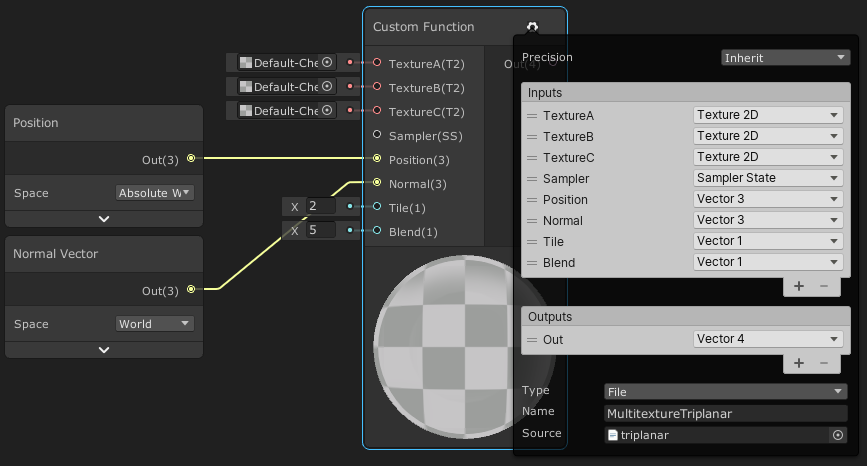
This post includes an introduction to using the Position node to sample textures rather than using mesh UV channels, which is also the basis of Triplanar mapping. It won’t be super in-depth but wil…
What's weird is that it looks like they used to have tiling and offset inputs, and now they don't. They just have "tile".
Looks like a good solution. I didn't know it's possible to add custom function node. That's much better than decompiling entire graph. Thanks
Yeah, then you can just remap the 0...1 result from your triplanar WS locations to your u...v location in your atlas.
The documentation page shows you an example of their "possible' math too.
https://docs.unity3d.com/Packages/com.unity.shadergraph@11.0/manual/Triplanar-Node.html
@woeful geyser
yep. That's what I'm doing rn 😛 . ty
lol, np. That's what I'd do too.
@meager pelican in the code you gave me, what is atten?
        half diff = max (0, dot (s.Normal, lightDir));

        float nh = max (0, dot (s.Normal, h));
        float spec = pow (nh, 48.0);

        half4 c;
        c.rgb = (s.Albedo * _LightColor0.rgb * diff + _LightColor0.rgb * spec) * atten;
        c.a = s.Alpha;
        return c;```

It's just a float, so I assume it's just changing the intensity of something, but idkIt was one of the inputs to the function I mentioned. It's the attenuation (so changes intensity by distance).
I think I gave you a link to the source.
And/Or showed the input.
Hm okay. Is it necessary to have that? I don't really know how I would get the attenuation in my shader
How are you getting the light info?
directional light, I'll share my code
            {
                // half3 normal = UnpackNormal(tex2D(_NormalMap, i.uv));

                float3 lightDir = _WorldSpaceLightPos0;
                float3 viewDir = normalize(_WorldSpaceCameraPos - i.worldPos);
                float3 lightColor = _LightColor0.rgb;
                float3 albedo = tex2D(_MainTex, i.uv).rgb * _Tint.rgb;
                float3 specularTint = _Metallic;

                // * This is the Blinn reflection model:
                // float3 reflectionDir = reflect(-lightDir, i.normal);

                // float4 diffuse = float4(albedo * lightColor * DotClamped(_WorldSpaceLightPos0, i.normal), 1);
                float diffuse = DotClamped(_WorldSpaceLightPos0, i.normal);

                // * This is the Blinn-Phong reflection model:
                float3 halfVector = normalize(lightDir + viewDir);
                float normalHalfVector = DotClamped(halfVector, i.normal);
                // * Now we just get the power to get the smoothness
                normalHalfVector = pow(normalHalfVector, _Smoothness * 500);

                float3 specular = lightColor * specularTint;

                float4 color;

                diffuse = diffuse * albedo * lightColor;
                color.rgb = normalHalfVector * specular + diffuse;
                return color;

}```could I do a max function? Like, max(1, _WorldSpaceCameraPos - i.worldPos?) and then multiply that or something?
well that got weird results, so probably not what I'm looking for
Directional lights have attenuation of 1, they don't attenuate. But IDK if there's shadow stuff in the mix or not. But for this, disregarding self-shadowing, or maybe use directional light intensity. I'm unsure right now and can't go look it up, ATM.
Hi how do I important a model from Blender to Unity with the shaders I built in blender?
You don't. You re-write the shaders in Unity. They don't translate from Blender.
Oh...
The model imports though.
Shadergraph is real I see
I mean I'm forced to used shader graph right?
(I don't actually wanna learn shader coding bruh lol)
No, you can code them the old fashioned way, with a text editor.
Or buy a different node-based editor, like Amplify.
But Shader Graph is the unity one for scriptable pipelines.
If you want standard pipeline, research "Surface shaders in Unity".
Or use amplify. But double check what I said before purchasing, I don't use Amplify or any of the other editors, so grain of salt.
Thank you @meager pelican
can I not accept an integer as input to a custom function?
in shader graph

I don't see it on the list of possible inputs
oh...
I use a float in Integer mode?
does that sound right to people?
And I don't seem to be able to set the integer option on a float... Interesting
I don't get the inout argument in a function for hlsl. Any explanations?
Wait....is that list from the CPU side? Or where? Use float, sure.
@wary jackal As for your question, on the HLSL params that have inout, it's passed in, and when you change it in the function, it's passed back out and updates the values so the caller will get changed values.
Params are always passed by value, however the compiler will update the values upon return for out or inout modifiers. It's weird.
Here: https://docs.microsoft.com/en-us/windows/win32/direct3dhlsl/dx-graphics-hlsl-function-parameters
A function takes one or more input arguments; use the following syntax to declare each argument.
So, it's basically as if the function had a return type of whatever you want it to be really without having to have a return type?... in my case it would be v2f
is there anyway to get the output color of an unlit shader graph through script?
im totally new to shaders, i have this shader that was built in the standard render pipeline and its just pink in urp
how do i convert the shader to urp
I am just confused haha. I've got an integer Index that I want to pass in to a custom function node
That's the list of possible input options
That unity is giving me for a custom function node
I need an integer cause I have to use it to index into a compute buffer, and I already have the integer
So if I connect it up to a float type input port
It'll be okay?
Float in integer mode yes.
Ask my question here or can I put the link?
https://forum.unity.com/threads/should-we-untick-static-batch-when-using-gpu-instancing.1124800/
Unity Forum
I would like to know if we use GPU instancing for objects like instantiated prefabs, should we untick static batch for them or disable static batching...
So I'm familiar with importing pre-packaged shaders (like this https://github.com/poiyomi/PoiyomiToonShader/releases/tag/7.1.60),
now I'm trying to figure out how to import a different shader that isn't packaged but is instead a project folder (ex: https://github.com/dsoft20/psx_retroshader ). What's the best way of importing this into Unity?
For that specific github its just a normal unity project, so the best way is to just open the project and see how the shaders are set up there, then copy that setup in your project
gotcha, thank you! ❤️
is there a function to transform a point using a 4x4 matrix
I can't figure out what the shader graph node is called
only finding Transform which goes between the various coordinate spaces
Can use the Multiply node
Yeah, it will be fine, you MAY have to case it to/from float to int or vice versa.
I am trying to just draw some cubes in hdrp
via the instanced api
draw mesh indirect
and I am having one heck of a time trying to get them to appear
You mean using GPU instancing as set up by the engine? So you have several game objects in the scene all using that cube mesh and you're writing a shader?
Or are you doing some procedural geometry, or some manual instancing?
I was generating meshes and drawing them, but I wanted to test how that compared to drawing instanced subsets
but to start I'm literally just setting up a compute buffer with 5 matrices
and trying to draw 5 cubes using those matrices
via the mesh indirect call
Look also at DrawProcedural and family.
I wrote a custom function node which looks up the matrix in the compute buffer and spits it out
but I am not sure if my shader is remotely correct
My thought process was get the object position, transform it using this localToWorld Matrix
and then transform it back to object space
and set the vertex position
but I'm looking at some examples and they seem to just be manually modifying the unity_ObjectToWorld matrices
which I thought wasn't quite something you could do directly in hdrp
I think it would help you to look into UnityObjectToClipPos(), as that's the one you normally do in a vert() function with an object-space mesh, and a transform on the game object. You'll need the camera's view matrix passed in or whatever the hell it is. There's a similar one for object normals too so you can do lighting.
So if you have (even an internal) unit-cube mesh, and you have passed in each mesh's 4x4 matrix, that function will give you what you need to output from the vert() shader.
This will help too: https://docs.unity3d.com/Manual/SL-BuiltinFunctions.html
It's the model-view-projection matrices, and with some research you can figure out what gets set and what doesn't by the engine. It's in the include files, and you can download shader sources too if you haven't already.
where can I grab sources?

Unity
Unity is the ultimate game development platform. Use Unity to build high-quality 3D and 2D games, deploy them across mobile, desktop, VR/AR, consoles or the Web, and connect with loyal and enthusiastic players and customers.
ah I had just found that
thanks
I am a bit surprised at how much harder this is compared to built in pipeline stuff
I thought this would be a relatively straight forward exercise haha
I'd say "different" or "more feature rich" but yeah. 😉
Interestingly, I woke up (wow, waking up thinking about GPU crap, sad) and started thinking about an article from AMD I read recently regarding generating camera facing quads in the vertex shader and NOT doing a geometry shader. And then I started wondering how VFX graph does it.
So BTW, you can do what you're doing (mesh locations) really easy in VFX graph, with mesh particles. IIRC. But it's not as fun as learning it yourself, and you're doing a learning exercise.
this is not a learning exercise as much as me wanting to see which approach I want to take 🤣
I'd much rather take a faster easier route
I haven't played with vfx graphs at all yet
I suppose experimentation (selecting approach) is a form of testing which is a form of learning a result, proving a theory. So...meh
ah absolutely
I just meant I'm cool with learning less if it means reusing other peoples stuff that works
at least for some pieces
Did you research things like "mesh particles" or "procedural mesh generation in HDRP"?
I haven't looked at anything particle related
I have looked at a bunch of mesh generation stuff
I have a jobs based system right now where I'm chunking things up
but it eats a fair bit of CPU
so I wanted to see what offloading some of that to the GPU might look like
Here's an interesting thing about instancing and vertex shaders. See slides starting at about 15 and particularly 17. He's generating quads from a data buffer location read. In a vertex shader.
IDK what DX level you need for that but I'm guessing 11.0 or 11.1. https://www.slideshare.net/DevCentralAMD/vertex-shader-tricks-bill-bilodeau
Although that's for quads, it isn't far removed from, say, a cube.

I'm not looking to target anything other than desktops
Frame Debugger
objA (instanced) --> this batch contains two same objects (ObjA)
objA (instanced) --> this batch contains three same objects (ObjA)
objA (instanced) --> this batch contains two same objects (ObjA)
It says materials are different while they have same material, WTH
I checked several times, that material is the same. When I change for example color property, it is reflected for all of them
They are batched based on distance, I think.
Another scenario
objA (instanced) --> this batch contains two same objects (ObjA)
objB
objA (instanced) --> this batch contains three same objects (ObjA)
objB between two same objectA, again break batching
Show a frame debugger screenshot of one you think is wrong.
There's several reasons, including you accidentally making a copy of a material.
Hi i've never really coded shaders could someone please try to help me? My goal is to make a unlit object be visible through other objects but with a lower alpha value. I did some research and think it has to do with the z buffer but just "turning it off" makes it completely visible.
OK but it is impossible. I change a prop in that material and all of them change. So the material is the same
Static batching might be making different mesh instances (it builds meshes), you posted about it! Did you turn that off, did it help at all?
In your screen shots, it's talking about DIFFERENT MESHES, not different materials. So changing material properties won't tell you anything in that case.
Done, almost solved
I changed queue to Geometry+1, WTH
It is not about static batching
Yes I unchecked static batch for all of them
About different meshes, it says related to the previous one not same objects
It is obvious that the weapon box mesh is different from the previous one p1911 or health box
It is all about render order. If I have different queue for thoese instanced meshes, the problem is solved or remove intermediate objects (yellow rect)
I said almost, because I should define different queue for each item type and instanced mesh
For example a weapon box has two meshes (up and down). I have to define as an instance Geometry+1 for up meshes and Geometry+2 for down meshes, messy
Therefore, all up meshes are rendered and then down meshes and finally can be batched correctly
Remind me, SRP or standard pipeline?
SRP batches differently than standard.
But it should sort that instancing stuff out.
How might I go about making a fragment shader that changes the color of a mesh based on the steepness of the vertices? I've seen Sebastian Lague do it a few times in his videos (erosion video most specifically) but I do not know how to approach this... Any ideas?
OK, the "steepness" would be a triangle's surface normal, relative to a horizontal or vertical normal.
Try subtracting the normal's y component from 1.0. That's one way. If it is pointing straight up, the result will be 0, and if it is pointing horizontally, the result would be 1 (cliff). It could be pointing downward in some cases, so you'd have to check for that if such is true.
Spitballing here.
Whatever result you get, you're aiming for a value between 0 and 1 so you can use it in a gradient lookup or some lerp or however you decide to color it.
Yeah using a lerp would probably be simple
hey guys sry if im interrupting anything but i need help making a standard pipeline shader work in urp
Should I do lighting as a separate pass?
@light epoch You can't really interrupt in this server, questions are essential (even if I have no idea how to answer them)
true
You can also try a dot product between your surface normal and some vector. Here's a good explanation:

🔽 Click
Clipped from the super long shaders for beginners stream of two days ago!
Note that this is for two normalized vectors, it's a bit different if only one or none of them are normalized. Regardless - the case of two normalized vectors is very common in shaders!
For example, Lambert shading is the dot product of the light direction and ...
Lighting is just "scaling" a color intensity, in the simplest case. Or adding specular in, say, a blinn-phong case. Or more elaborate in a PBR case.
So then, no not unless there's multiple lights
But if there are....sure.
But unity's default stuff calcs some basic per-pixel lighting as it colors too. Then adds later in things like "forward add", for example.
anyone have any tips for why apparently UNITY_INSTANCING_ENABLED is never defined for a shader I'm drawing with the InstanceIndirect API?
I've got instancing enabled on the material too
I'm inside of shader graph if that matters, as a custom function node
I guess it all depends on what you're trying to accomplish
Is it a vert/frag? If so, did you use #pragma multi_compile_instancing?
I had a pragma multi_compile
Ask, and then pray. 😉