
#archived-shaders
1 messages · Page 198 of 1
but when I look at it from this angle, I am still able to see through it

I'm using URP material with Surface Type set to "Transparency" as I want to make it being able to do a fade away animation later on.
A transparent material with 100% alpha will not render the same way as an opaque material
setting it to Opaque does solve the problem but I won't be able to fade it away later on.

So i'm asking what would be the best approach to do a Fade Away Animation and at the same time not encountering this issue.
yeah I've just come to understand that. How would I be able to approach a Fade Animation? Do I need to set it as "Transparent" in order for it to be able to fade away? Or is there a way to do it even if my material is set to "Opaque"?
any help would be much appreciated. coz I'm stuck here. Thought it would be a simple solve. Thanks in advance!
The issue appears when you have more complex meshes with transparent materials
It has to do with how the renderer sorts faces. In your case you should leave the handle as its own mesh, so it will not conflict with the larger mesh
I wanna add a shooting range,just like this

Like the mark when painting terrain
How to do this?
Hey, so I'm not sure if this is the right place to post this but the project I was working on was updated (without my knowledge) from unity 2019 to 2020 now the problem is that I build some shader graph shaders and I was using the Custom Function node to get the lightDir after the upgrade was done all my materials were erroring out(getting syntax error in the custom node). Has anyone else encountered this problem or have any solutions? Any help would be greatly appreciated. Thx
Usually the syntax error gives you more information about what the problem is, but if it's been upgraded to URP v10 I would assume it might be because #if SHADERGRAPH_PREVIEW is being used instead of #ifdef SHADERGRAPH_PREVIEW as that's a common issue. You may also want to check the things listed here to see other changes : https://docs.unity3d.com/Packages/com.unity.shadergraph@10.3/manual/Upgrade-Guide-10-0-x.html
This worked perfectly, Cheers and thx a lot you really helped me out
are there any good resources for more in depth/complex use of compute shaders in unity? I can only seem to find the ones that get you started
Also anyone have any more suggestions for debugging compute shaders/profiling parts of them?(again, I know where the slow downs is, but I dont know what parts of it do so(recursive looping using a stack for BVH traversal))
Hi, is there an easy way to randomly rotate Quad of the mesh?
I have created a billboard from a quad. But it's repetitive on sides

I assume one mesh contains multiple quads?
yes
i've turned this

into this

the last thing I need is to quasi-randomly rotate the texture on a quad.
You could rotate the UVs (or the quads) based on the quad center position 🤔
How could I get quad center position?
How do we get syntax highlight, intelisence and tabs working properly with compute shader on visual studio?
Hi, I just wanted to know how to make an additive shader with shader graph. Essentially what I want is for my bullets to be brighter as they overlap with things and I wasn't sure how to do that. This is what I have so far

From what I understand, additive blending is adding the RGB values of the pixels to what is already there, but how do I portray that using shader graph? I'm guessing it's fairly easy but I'm very new to this
It would be an option on the small cog on the master node, (or Node Inspector window in v10) but annoyingly I don't think Shader Graph includes the blend mode option for the Sprite Master node/stack, only the regular 3D Unlit/Lit has it. :\
You'd probably have to generate shader code from the graph (right click master node), and save it as a separate shader and edit the Blend mode manually. Blend One One would be additive.
Ah
I've never played with code using shaders ever
Do you know where I could look to learn how that works?
There are tutorials for shader code in general but editing the code generated by the graph shouldn't be too difficult. It would be completely separate from the graph then though so if you want to make further changes you'd have to generate code and edit it again.
You'd only need to change a couple lines that probably include Blend SrcAlpha OneMinusSrcAlpha to Blend One One. Blend is part of the shaderlab syntax. https://docs.unity3d.com/Manual/SL-Blend.html
Okay finally got it to open. Is it just the code right at the start because this code is like 5000 lines long?
When I tried to open it I was getting this error:
5000 lines seems quite long. It's only roughly 750 lines in v10+ but maybe it generates differently in older versions idk. You'd probably just need to alter the Blend on the Pass tagged as Universal2D.
how do i make a property a whole number?
where can I find more in depth/complex uses/examples of compute shaders? most of the stuff I am finding is based around introducing compute shaders, but im trying to find ways of optimizing it
Int
can anybody help me?
Unity Forum
Hello,
I have been trying to mask a 3D object using a 2D sprite rendered on a Canvas using Screen Space - Camera with an Ortographic camera. This will...
could someone please help 🙂
Don't suppose anyone's made a god-ray shader for URP?
@royal prism just render the 3d object to a render texture and use that texture in your ui.
anyone know of a method to use the same shader for an in-world quad and something in a canvas?
Just... apply it to both?
don't you normally need a material to use a shader?
hm ... apparently images have a material, didn't realize that
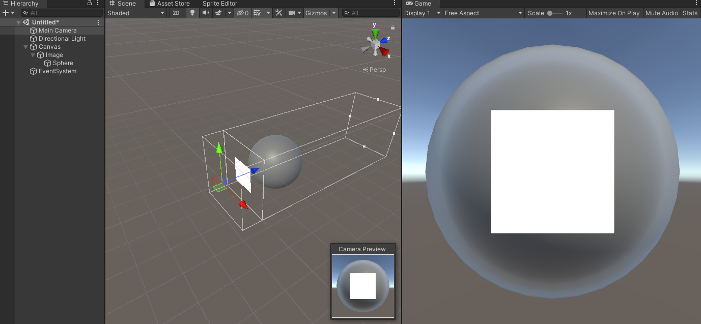
Can someone explain why this is ending up as a flat white square instead of the actual image?
_MainTex("MainTex", 2D) = "white" {}

Tags {"RenderType"="Transparent" "Queue"="Transparent" }

float4 frag(Interpolators i) : SV_Target
{
    float3 circle = tex2D(_MainTex, i.uv);
    return float4(circle,1);
}

because you're not using the alpha at all
is there a version of tex2D that returns alpha info?
It is the 4th channel
I know it is rgba but how do you access it?
ignore me, I must have had some other issue the last time I tried having it return a float4
Use float4 inst... oh, you got it =p
because the last time I tried my code wouldn't compile, there must have been something else that I just happened to screw up at the same time
@shadow kraken the handle is in its own mesh but I am still able to see through it when the handle and the wall is attached with a Transparent Material


even just the wall itself, I can see through it and see the edges.. the wall is just a cube stretched to be a rectangular cube


then when i switch back to "Opaque", everything just works fine

I disabled every other Object to make it clearer. So this is the wall (cube)

there is a handle below it as a different object

once i make the material Transparent, it becomes like this

but I want it to look like this even with the Material set to Transparent. I only manage to make it look like this when Material is set to Opaque

Reason why I need to set the Material to Transparent is because I needed to do a Fade Animation later on.
My grass shader is currently looking like this, darker in the bottom and lighter in the top. I wanted the color to be uniform so they would blend together. Does anyone know how to do it?

I also want it to have the same color as the ground below it, so it blends and become a single color.
code at the moment is this, on the surface part:
`void surf (Input IN, inout SurfaceOutput o)
{
float2 spriteSize = float2(8.0,1.0);
float vel = 100.0;
float2 animTex = IN.uv_MainTex * 1.0/spriteSize;
animTex.x += floor(fmod(_Time.xvel,spriteSize.x))/spriteSize.x;
animTex.y += 1.0-((1.0+floor(fmod(_Time.xvel/spriteSize.x,spriteSize.y)))/spriteSize.y);
fixed4 c = tex2D(_MainTex, animTex) * IN.color;
o.Albedo = c.rgb;
o.Alpha = c.a;
clip (o.Alpha - _Cutoff);
o.Alpha *= IN.color.a;
}`
it is set to have no light or shadows, like:
#pragma surface surf NoLighting vertex:WavingGrassBillboardVert noshadow noambient novertexlights nolightmap nodynlightmap nodirlightmap nofog nometa noforwardadd nolppv noshadowmask
WavingGrassBillboardVert is all commented, excepted the call to this function:
void TerrainBillboardGrass( inout float4 pos, float2 offset ) { float3 grasspos = pos.xyz - _CameraPosition.xyz; if (dot(grasspos, grasspos) > _WaveAndDistance.w) offset = 0.0; pos.xyz += offset.x * _CameraRight.xyz; pos.xyz += offset.y * _CameraUp.xyz; }
I'm trying to achieve a grass similar to this

any tips?
@eager folio but it wont have animations in that case 😦
Why couldn't it be animated?
The characters in my game are done that way, and they are animated.
Sorry maybe i didnt understand render texture before but as i read now it will update realtime my 3d mesh it renders, so if the 3d mesh has animation, it will work. To givd you some context; i use it for a loading screen, the loading screen has 2 or 4 area’s containing the 4 player. But their mesh is sticking out of their area, so the sword of character 1 enters the area of character 2 making it look messy. So rendee texture could be the solution?
this does look really nice
kind ghibli style?
i want to achieve ghibli style too in my projects 😄
Hey, I made a (kind of) fire shader with some noise and so on (pretty beginner). I wanted to test how it looks with text (burning numbers seemed cool).
As expected it didn'T work 😅
With standard Unity UI Text it just got invisble when I assigned the shader.
With TMP I get the blocks in Scene View, but nothing ends up getting rendered.
Can someone point me in a direction on what I'd need to look after to get that to work?
It should work with TMP if you get the text texture in your shader. Look at a text mesh pro shader to see what is the property name, and add it to your shader.
Sample the texture and apply it as a mask to your effect.
Doesn't TMP use SDF rendering?
It does.
Okay, will try that. Grabbing the text texture was also my thought, but I was still looking what node or smth I should use for that
It just needs a property in the blackboard with the same reference name as the TMP shader, and a sample texture 2D node.
I just need to find the standard TMP text shader again 😅 xD
I suppose this is what I need?

Yep, "_MainTex" seems to be the one
There seems to be more to it 😅, doesn't work yet
I have a lot to learn
@mint storm I suggest using this technique as outlined in this article, it is a common approach to this problem used in many games over the years. While the article is for URP the technique can be applied to standard. https://danielilett.com/2020-04-19-tut5-5-urp-dither-transparency/

Daniel Ilett: Games | Shaders | Tutorials
Drawing objects with dithering patterns
Would it help for more tips to give a screenshot or smth to you? Or should I for now just try to do more tutorials on shadergraph?
A screenshot of the current shadergraph and the result would help 😉


Camera sees the same on preview, but disappears when hitting play
Is the reference name of the texture property also "_MainTex" ?
xD, nope
Texture2D_73a64a6ace094b1bb7563de9698c4731 atm
I think you should try changing that
Hey guys, how do I add a delay to this?

Maybe an Add (substract) between the time and multiply?
I changed it to _MainTex and it worked halfway xD.
It's just pulsing once a sec, i want it to pulse the exact same speed, but with a delay between pulses
it grabbed the corresponding texture, but now the text is invisible in every view

Hello guys, I am trying to learn shaders but I am having this issue. Visual Studio is not showing solutions. For other scripts works fine, but for shaders don't

Try to use only the red channel of the texture as mask multiplier, I don't remember if alpha is 0 or 1 on these.
If you want pulsing you could also try SineTime+1 which would smoothly alternate between 2 and 0. if you halve it 1 and 0.
I am sorry. I don't understand what you mean right now
sample node -> take only R output to multiply node.
Like this

Hm. For a moment it uses turquoise blocks, but then invisible again when I hit play.
yes, but that's not what i want.. I want it to pulse, and they stay, and then pulse again, etc
Essentially i think I'm looking for a sawtooth pattern that has delay

looks terrible lmao
Yeah, thinking of a way to fake it
What does it look like right now in the editor ?
Maybe try the triangle wave node

you could go on and scale it up a bit, then substract a flat value (to make the "gaps" bigger, where the graph would be negative), then use a clamp node to trim the negative values to 0
Hi, is there any way to get Quad Center position information?
makes sense 😄 I'll try it
Hey there! I straight up copied this shader graph: https://www.youtube.com/watch?v=kCaVBAlwaCg
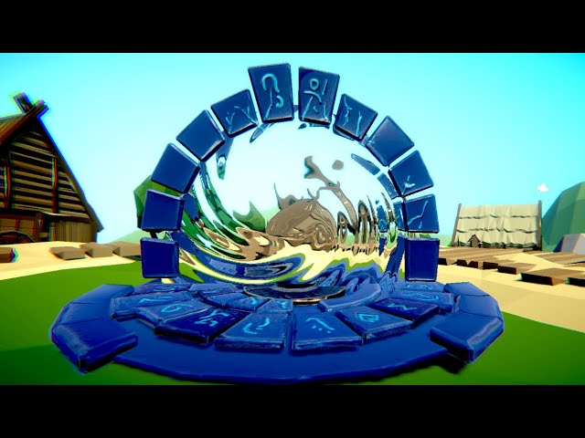
This is a quick Tut on creating a portal shader in Unity 2019 using shader graph, it uses the camera texture with some fake refraction on it
This material is part of the LWRP Material Pack Vol 2:
https://bit.ly/lwrp-materials-2
Checkout my Low Poly Floating Islands package:
https://bit.ly/lwrp-floating-insland
Buy my LWRP Material Pack to su...
and my result isn't the same as in the tutorial at all:

(URP is on )
Did you enable the opaque color texture in your render pipeline asset ?
here, or on the other one?

OH MY LORD
okok i got it, thanks so much!
(so now i figured why all my shaders didn't work)
So I was wrong, the tmp texture is alpha channel only, so you need to use the A output of the sample node.
Also, I figured out that tmp is a bit ... agressive about the material assigned on the mesh renderer, and systematically replaces it with the one generated from the font asset.
It looks like this now in Scene mode xD.
Waving around in the atlas

but still disappears on start, which probably is connected to your second message
It should look like this if you display the tmp texture :

Maybe because I am pulling the UVs from a lerp with noise?
If you pass the sample result in a smoothstep node you can vary the "width" of the effect, and blend with you fire. 0.5 is the glyph "base" edge

Oh, indeed, I didn't pay attention to that, you should just use the default mesh UVs to sample the text texture (unless you want to deform them a bit)
If you want to distord UVs, don't lerp with the noise, but add the noise to them
I mean, I sent a screenshot of the whole thing earlier. I am not very experienced yet, so I just followed a tutorial
This is what I meant. Could you give me a bit more intel on why adding is better than lerping here?

Here is a good example of how to distord the UVs :

Man, you're fast....
Lerping toward the noise value will distord but doesn't give you good control over the effect, as it will result in uniformly changing the UVs toward a static value.
Adding the noise will act like offseting them, keeping the initial information.
In my case, I take the 0;1 noise value, transform it to -1;1 range, and multiply with an intensity (0.003) to control the effect. Adding this to the UV will keep the general "shape" of the glyph (as the middle of the noise is 0) and will distord it.
ah okay. Thanks for that explanation.
Thinking about how I can combine this with mine atm
well, thanks @mild dirge

it worked
this is scuffed
im sure there r some unnecessary stuff there
I just tried a bit, this is what I did

oooh
Ok, seriously.. How are you supposed to write shaders for URP?
Is Shader Graph the only option???
depends how experienced you are, if you are familiar with shader code by all means jump in and write as normal. If you look in the packages folder there is the universal shaders where you can look up all the specific URP nuances and Unity macros etc.
Otherwise there is shader graph or ASE from the asset store.
Editing the generated shader doesn't work, nor does "Compile and show code"
I want to edit the actual source of the shader, no visual scripting
I assume the tutorial used Lerp because they wanted a property to control how much the noise influences the UVs. With your apporach I'd just multiply it beofre feeding it to the Add node?
Yes
I believe on newer version "copy shader" from inspector in unity, then paste into a file should work
Oh lord, so it's not that smooth of a transition?
Thanks though.
What is the reason you didn't multiply the Colour (in my case, from the tutorial, an HDR) with the out of the blend nopde at the end, but rather just plugged it into the Base Color?
I my case the shader was set to alpha blend mode.
I only need the alpha to mask the output and wanted a flat color. If I'd multiplied the color I would have a black outline visible on the effect.
this?

The "blend" setting, yes.
hm, kinda interesting. The thing with not visible in play mode way due to settings in the canvas I noticed.

Sadly the glyphs move out of their bounds xD. But has a nice neon effect I guess
This is what I ended up with though

Thanks a lot for all the help @amber saffron
❤️
It's probably the distortion that is pushing the glyphs out of the mesh rectangles.
Try raising the scale and lowering amount
Yeah, that helps a bit. Still sometimes cut edges, but better overall 😄
I think my inital hope was, I could just apply it to the finished texture or whatever TMP has at the end, but on this way I understood, that the approach that this shader uses isn't fit for that.
How it was used in the tutorial was feeding a kind of flame texture (only consisting of different alphas of white) to be distorted and then they just put that on a Quad or smth
So they disregarded the original look of the object and only manipulated the the one texture that was provided.
But in TMP case the texture they used is an Atlas which they cut the different glyphs out of, so if I distort the values too much, they no longer fit TMP interal copy and paste stencil.
Also, sorry if I use words wrongly xD. I kinda get the feeling that stencil has its own meaning in the context of shaders
I'm thinking a shader would be the best way to fake this visual effect? Does anybody have a suggestion as to if there is a better thing to use? 👀
https://youtu.be/txkRCIPSsjM
hi! i've got my shader code...
and it does that nice animated texture:

but i'd want to implement it into a shader graph, to combine it up, for example, with this other shader:

that was previously made in shadergraph
how may i do...
i thought with a custom fonction, but i don't really know how
Yeah, I think there's a way to make custom nodes and/or subshaders. But sadly I can't tell you how
okay, don't worry, i can easily wait for you or someone else :)
You can use the custom function node to add code to you shadergraph
i tried, and... Got a bunch of errors ^^'
Plus, what is the return type of this custom function?
so, of my shader, basically? It's a Float4, i get it, but... Where can i input this next? Do i need to put inputs on this function?
It's whaterver you decide to return. You have a configurable list of inputs and outputs on this node.
well i don't know lol, does it need input? It used to calmly play this texture, so i guess not, right?

i-
sorry, i really don't get what i'm doing with custom functions 🥺
Are you trying to use one of the output values of the node in the code without it beeing assigned something beforehand ?
my bad, i didn't type the name of the fonction ^^'
(btw, here is the doc link of the node : https://docs.unity3d.com/Packages/com.unity.shadergraph@11.0/manual/Custom-Function-Node.html)
well, problem here is my code, i believe

seems to have a bunch of errors
(i imported it into a text asset, with hlsl extension... would that be the way i should do?)
(knowing i didn't modify anything for now, it's basically the same code than here but in a text asset in .hlsl)
Ok.
The custom function node acts just like a way to write your nodes easilly, it doesn't replace a full shader.
You need to "extract" the vertex and fragment operation of your file into indivudual functions with their inputs and outputs, and link this in shadergraph.
ooooooooooh!
so basically i've got several "blocks" here, several "functions"

and i'd have to put one function node per function, with each corresponding-
inputs and outputs?
"one function per function"
Not all, only the ones you'll actually use. Because all the code functions are in the same file, then can call each other, but you need to identify the ones that are the final "output" of the shader.
You should probably look at a function named "frag"
yup, definetly
(sorry, it's in the last screen)
it's the one
So, the frag function here is all what your need
but something's bugging me, it's that it needs a "v2f", right?
To "convert" it to a custom function node, you need to get rid of "v2f i", which is the vertex input to fragment.
Note that in the code the only relevant input is "i.uv" => those are the texture coordinates.
Also, a custom function doesn't output value, but modifies out variables.
So :
- Change the fonction declaration to something like
MyFunction_float( float2 uv, out float4 o)(remove SV_Target) - remove the
float2 uv ...line as the variable is declared before - change
return float4(...too= ...
In the node settings, add a "uv" float 2 input and a "o" float4 output to match the function declaration, and type the same function name MyFunction without _float (precistion identifier).
and connect a UV node as input
@amber saffron Would you mind helping me with something?
ooookay, thanks! i might get back here, but i'm gonna try my best!
You know what the sage said : Don't ask the permission to ask a question, just ask the question.
(just before i "leave":
`float4 frag_float (float2 uv, out float4 o){
uv = i.uv * 10.;
float a = abs(n(float3(i.uv + _Time.y * 3.14, sin(_Time.y))) - n(float3(i.uv + _Time.y, cos(_Time.y + 3.))));
o=(0, .5 - pow(a, .2) / 2., 1. - pow(a, .2), 1);
}`
I need help with developing a custom lighting shader for my voxel game and with Unity, it seems a bit complicated. Pseudocode here https://gamedev.stackexchange.com/questions/152559/achieving-2d-lighting-for-terraria-like-game

Game Development Stack Exchange
I'm trying to achieve the fog-of-war lighting style that Terraria and Starbound have. Terraria's lighting system seems to be more blocky/tile based, but Starbound's is a lot more smooth.
The Desired
is this what you meant?)
Yep, that's good. You could even get rid of the line uv = i.uv * 10.; as this is something you could control (uv scale) with nodes.
for each light on scene:
    if light is on screen:
        add light to the drawing queue

draw frame:
    render frame color map:
        draw each visible tile and object

    for each light in queue:
        trace secondary lights on visible cells and add them to the drawing queue

    render frame light map:
        set blending to additive
        for each light in queue:
            move light object to the light position
            set light object width and height to the light radius
            set light object color to the light color
            draw light object
        //then we render shadows for solid places
        set blending to subtraction
        for each visible cell:
            if cell is surrounded by other cells from every side:
                move light object to the cell
                set light width and height to the radius slightly bigger than cell
                set light color to white//to subtract any kind of light color
                draw light object

    set blending to normal
    draw color map
    set blending to multiplication
    draw light map
it doesn't recognize "i" 😰
no i.uv, just uv
What did you already try ?
(all this for that .__.)

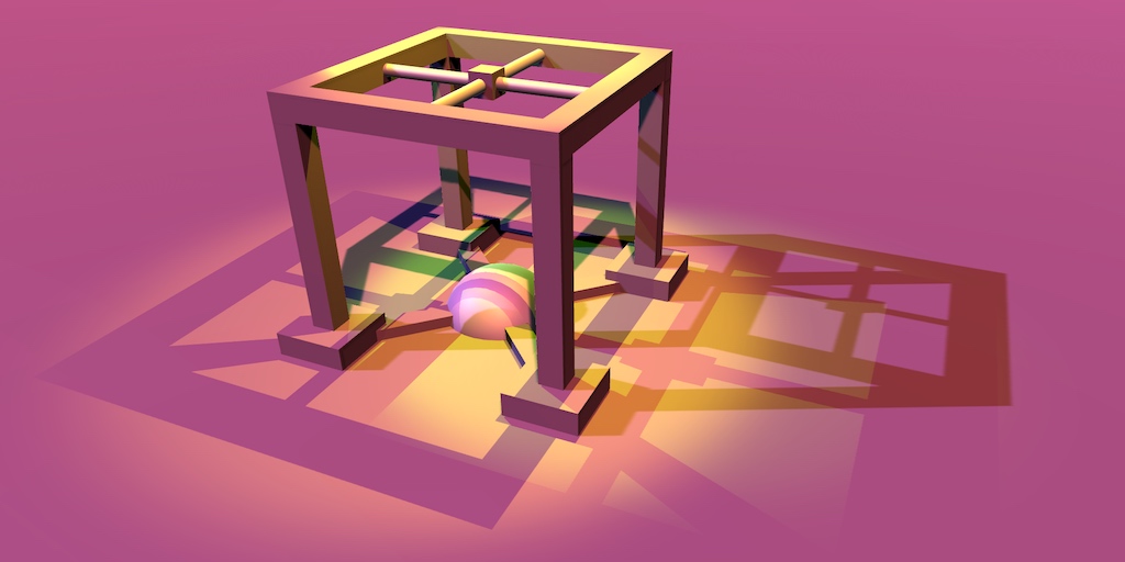
Nice sphere
x)
it should've been like that, but blurry basically
I have a mesh with vertex colours which work as a pre-calculated light, but I have no idea how to implement this in order to have it normally working even on objets which are not part of Voxels
Did you input UVs to the custom function node ?

(i cut the output for now)
but basically what i did was simply adding it to my other graph:

Are you using built-in renderer or URP / HDRP ?
URP in a 2D project
Oh, I missed the _Time variable in the code. You'll need to add a float1 input to your node where you can plug in the time node
Is there a reason to not use URP 2D lights feature here then ?
oooh, that's what i thought! thanks!
Precalculated voxel lights based on Flood fill algo are extremely performant and look better compared to dynamic lights


and now it... Hmmm...

`float4 frag_float (float2 uv, out float4 o, float1 _Time){
float a = abs(n(float3(uv + _Time * 3.14, sin(_Time))) - n(float3(uv + _Time, cos(_Time + 3.))));
o=(0, .5 - pow(a, .2) / 2., 1. - pow(a, .2), 1);
return o;
}`
Look maybe in the api if you can code the shape of freeform 2D lights ? https://docs.unity3d.com/Packages/com.unity.render-pipelines.universal@11.0/manual/LightTypes.html#parametric
(removed the ".y". Was i right, since it's a float1?)
yes
in the function declaration, replace "float4" by "void"
and no "return o;"
oooooh okay
wait so

there's still an output here, right?
oh wait, realised i affected a float1 value to my "o"
oh no, nvm
Yes, it's the variable with "out" in the declaration. BTW, order is important, inputs firsts. :
void frag_float (float2 uv, float _Time, out float4 o)

Just to avoid any naming issue, rename the function please 😓
"frag" is very frequently used for declaring the fragment shader function, and it might conflict with something
lol, if i rename it, it'd be "void" because it's a void texture for our void bending mage 😭
i'll manage lol
yup, done, i've renamed it

Hum ... Can you show the current full code (use a service like hastebin if necessary) ? This error message doesn't really help me.
my shader code, or the error code?
shader code
float n(float3 x)
{
    float s = noise(x);
    for (float i = 2.; i < 10.; i++)
    {
        s += noise(x / i) / i;

    }
    return s;
}

void darkness_float(float2 uv, float1 _Time, out float4 o)
{

    float a = abs(n(float3(uv + _Time * 3.14, sin(_Time))) - n(float3(uv + _Time, cos(_Time + 3.))));
    o = float4(0, .5 - pow(a, .2) / 2., 1. - pow(a, .2), 1);
}
apparently, the third line is what makes it bug
Else, you could render your polygon lights in an off screen render texture, and blend it as a full screen image in multiply mode.
oh.
There's no noise function.
IT : WORKS
finally 🙂

i'll put you on my special thanks in my game, Remy
i won't forget about what you did for me
Happy to help
@amber saffron Wow, thank you Remy for help. Those 2D sprite lights are a nice compensation for vertex calculation

I can finally move forward
I don't really know what's I'm looking at in this screenshot, but if you're happy, I'm happy
Well, just made voxels and needed some sort of lighting like in Terraria/Starbound
The current presentation is purely for testing
Can I use the same shader on different meshes to use different data? I have a terrain split into multiple meshes (not using Terrain) and I'm trying to use one shader to show different parts of heightmap/etc. on each of them. I swear my calculations are at least vaguely correct but it looks like nothing even gets offset.
Is there a way to make a material pop something at given intervals?
to show what's going on: left is unsplit mesh of 224x224. Middle is split. Right is 512x512 split. All same seeds.

there's some other weirdness going on too but no offset at all is way more upsetting
I might want to... Reach out for help, again ^^'
so i've got my shader, again, but thing is it's a bit too """"zoomed in""""... What should i do if i want to """"unzoom"""" the "texture"?

Try using the Tiling And Offset node on the UVs (or just Multiply by a Vector2)

No, multiply the -->UV<-- node

You can, but you basically need multiple materials.
so this wouldn't actually work?

and I have to split the heightmap data just like my mesh?
If i'm not wrong, this is simply sampling the heightmap based on the vertex index.
What are you expecting/trying to do ?
If it's to have a single heightmap, but multiple terrain meshes, you could offset the X/Z value with the mesh pivot position to also offset the sampling
Sorry, I've read to fast, that's what you're already doing, right ?
I'm expecting to get results similiar to the left one (unsplit). I have to split the mesh because I cant go beyond 254x255 withouth going the vertex limit for a single mesh
Not that you can switch to 32bit index to have higher polycount if needed.
you can? 😮

Else, if you want to keep the split mesh route, you need to pass a different MeshIDs to each section. It can be done by using multiple materials (but still same shader), material property attributes or maybe additional vertex stream
considering I don't even know how to do lighting yet, it seems a lot to bite through. But I'll look into both options.
I but I thought materials were for texturing, which makes partly sense as I'm also colouring, but meshes are also near-identical (only one row has weird issues)
some shader graph experts here?
If you have a question just ask it, don't ask for experts
i look for someone that can help me integrate a shader into terrain
i have zero exerience so thats why i look for someone
@thick fulcrum hey I know it's been a while.. but I've looked into the link u sent and it's working good so far.. Thanks for the help! Really appreciate it!
I created a new material for each of my meshes and offsetting it. It definitely has an effect on my colouring (almost fixed it already) but my mesh vertices are still, of course, not offset like before...
I was technically giving each section a different MeshID. On the CPU side, I'm creating the initial meshes, and to the attached script component I'm giving them a (x,z) position, so when it's 4x4 meshes the value ranges from (0,0) to (3,3). Those values are fed into the shader as input, so e.g. (1,0) should have offset by 127, and (1,1) offset by 127 (x) + 127 rows (z)
(ayo Remy, remember the shader we worked so hard on? I made another one and went like "oh well, that was way simpler and looks way better, and is closer to what we wanted" lmao)

closer to the d a r k n e s s
but now i'd want some kind heat distortion that'd fit well, but i don't know where to begin with
any ideas? 🥺
Scene color node will be your friend here ?
Well, if you know how to use it, simply distord the screen space UVs as input and you'll have a distortion effect
I am looking for a way to add per instance normal maps to a shader.
Currently only the colors are per instance as in the shader below
Does anyone know if this is possible and how I would implement this?
I am lost since most guides only cover colors being changed.
{
    Properties {
        _Color ("Color", Color) = (1,1,1,1)
        _MainTex ("Albedo (RGB)", 2D) = "white" {}
        _Glossiness ("Smoothness", Range(0,1)) = 0.5
        _Metallic ("Metallic", Range(0,1)) = 0.0
    }

    SubShader {
        Tags { "RenderType"="Opaque" }
        LOD 200
        CGPROGRAM
        // Physically based Standard lighting model, and enable shadows on all light types
        #pragma surface surf Standard fullforwardshadows
        // Use Shader model 3.0 target
        #pragma target 3.0
        sampler2D _MainTex;
        struct Input {
            float2 uv_MainTex;
        };
        half _Glossiness;
        half _Metallic;
        UNITY_INSTANCING_BUFFER_START(Props)
           UNITY_DEFINE_INSTANCED_PROP(fixed4, _Color)
        UNITY_INSTANCING_BUFFER_END(Props)
        void surf (Input IN, inout SurfaceOutputStandard o) {
            fixed4 c = tex2D (_MainTex, IN.uv_MainTex) * UNITY_ACCESS_INSTANCED_PROP(Props, _Color);
            o.Albedo = c.rgb;
            o.Metallic = _Metallic;
            o.Smoothness = _Glossiness;
            o.Alpha = c.a;
        }
        ENDCG
    }
    FallBack "Diffuse"
}```How can I pass in a struct to a shader
like this
            struct Shape
            {
                int Type;
                float4 Settings;
                float4 Color;
                float3 Position;
                float3 Scale;
            };
It's not possible to pass in a single struct variable. You can pass in a buffer/array of structs using ComputeBuffer.
I don't think it's possible to GPU Instance textures. Everything in the draw call needs to use the same texture afaik. You might be able to pass in a Texture2DArray of multiple textures (assuming they are supported on your target platform), and instance a float to pick which slice index of the texture to use though.
Or maybe use something like a texture atlas and instance a tiling/offset value to alter the uvs to pick which part of the texture to use.
i tried that but i get the error setdata must be blittable
Can you post the C# struct you made that mirrors the one above?
Thanks!
I fixed it i was passing in the component instead of the struct
Hey guys ! does any of these error talk to someone ? i'm quite lost with shader ...

those are pretty standard syntax errors
but - if it's an HDRP shader
they're notoriously difficult to write manually in HDRP
i just contacted the author he had to recompile it with Amplify Shader Editor with latest version and it worked ! 🙂
I've got a problem and maybe someone knows more than me about this.
If I use a material other than the auto-default in on a rawimage, it isn't rendered. It's just invisible, not a white box or anything.
The problem is only on MacOS builds. Windows builds are fine as is the editor in both Windows and MacOS.
The problem persists both with the current 2019 LTS and 2020 LTS. Tested with built-in pipeline and URP.
Is a company's style copywrite?
As in could you actually use this in a game?https://www.youtube.com/watch?v=Frx8FNkt9HU
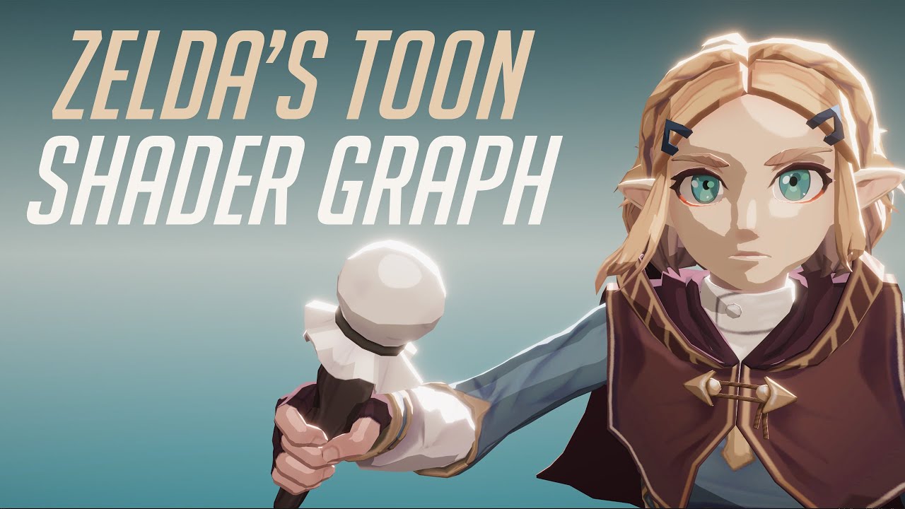
In this video we will show how to re-create Zelda Zelda Breath of The Wild Toon Shader Graph in Unity engine.
Download project files (Patrons only): https://www.patreon.com/BinaryLunar
00:00 Intro.
02:00 Setting up the scene and the character.
03:50 Creating a Custom Function node to get the main directional light data.
05:25 Calculating the p...
how would you go about creating a rotation effect in shaders?
I have this:
float2 adjustedCoord = i.uv * 10 -5;
float sdf = SDF(adjustedCoord, float2(0, 0));
float2 rotatedCoord = float2(.5,.5)-i.uv;
float angle = atan(rotatedCoord.y/rotatedCoord.x);
angle += _CosTime.a/2+UNITY_PI;
rotatedCoord = float2(cos(angle),sin(angle))*sdf/10;
rotatedCoord = float2(.5,.5)-rotatedCoord;
and it kind of works, but, the texture gets some artifacting at the top and bottom as it rotates throw that axis, is there a standard/better way to achieve something like this?
I'd use something like what shadergraph generates for it's Rotate node :
void Unity_Rotate_Radians_float(float2 UV, float2 Center, float Rotation, out float2 Out) {
    UV -= Center;
    float s = sin(Rotation);
    float c = cos(Rotation);
    float2x2 rMatrix = float2x2(c, -s, s, c);
    rMatrix *= 0.5;
    rMatrix += 0.5;
    rMatrix = rMatrix * 2 - 1;
    UV.xy = mul(UV.xy, rMatrix);
    UV += Center;
    Out = UV;
}
Toon/Cel shaded is pretty common so should be safe. Obviously can't use models/characters from zelda though.
Thanks, that solved the issue I was having! still not sure why my solution wasn't working, but I'll take it lol


no, it's not
as long as you make your own models
shader's can't be copyrighted
I'm gonna just buy RealToon
Hello, I am working on a terrain shader using Shader Graph and would like to ask how to get the steepness of the mesh?
I want to apply rock texture where the terrain is steep enough, how could I achieve that? Also I am not using Unity's terrain, but rather custom generated mesh (plane)
@dusky tusk Store vertex normals in the mesh. Do some googling to figure all this out and if you've otherwise messed with the mesh's orientation, but otherwise it's some dot-product with a worldspace up vector. Line N dot U (where u is up, and N is the pixel's surface normal). But I didn't look it up. So what you get back is the "steepness" in a float.
May have negatives, so you may need an abs() or reverse some signs. Play with it and/or ranges.
It's a lot like a lighting calculation, since steepness is basically how much it points away from "up".
If your terrain mesh is an even square grid then no dot-product is needed. I'll put a Stack Overflow link here that explains math in detail: https://stackoverflow.com/questions/6656358/calculating-normals-in-a-triangle-mesh/21660173#21660173

Stack Overflow
I have drawn a triangle mesh with 10000 vertices(100x100) and it will be a grass ground. I used gldrawelements() for it. I have looked all day and still can't understand how to calculate the normal...
Hey, I've achieved the more or less desired result using the following graph

And then I connect the saturate output to a lerp node that interpolates from one texture to another

oh you had normal vectors already? yea that works fine 😄
I am using this to lerp the albedo maps, although is there a way to interpolate normals?
If I use lerp it doesn't seem to do anything. And normal blend just combines normals
You'd most likely have the same effect if you could
Hi guys, how do I use shader graph shaders with ui image? I already have canvas set to camera, and it was working before. Guess it stopped when unity restarted..
Old material setting:
urp -> lit

changed it to simple lit like this

will this increase performance or since i use such a 'basic' lit version it doesnt?
(mobile)
Hi! I'm having an issue and I guess it's related to Shaders rendering, I'm getting around 60k Tris count when running my HDRP project on Windows machine with 2080s GPU, same project runs on Mac machine with Metal API GPU and I get 30+ million Tris! any idea what's the reason/how to fix it for the Mac?
PC stats

Mac stats

same scene, same camera angle and everything
hi there! i've got a "simple" shader graph here:

and what i'd want is to have my darkness output to be applied on a texture, that i could put here:

(its a radial slider from a certain asset)
how could i do? Apply it to a render texture? how? 🤔
(knowing my custom function outputs a float4, which is basically some UV mapping i believe?)
(Hi @amber saffron lol, finally found an utility to this hell of a custom function)
For the moment, there is no way to render a shadergraph to a texture. The float4 output of your custom function is a color (no UV), why don't you simply use this instead of a texture sample ?
what do you mean...? I can't put this directly on the Texture field i've got
No, but it connects to a color output of the shader ...
Why don't you use this shader on the material you want to directly, instead of trying to render it to a texture and assign it in an other material ?

Oh, okay.
I guess you can't (or don't want to) create a new shader to combine them together.
Well, the easy, but not optimal, way is to assign the "darkness" material to a quad, and have it rendered to a render texture by a dedicated camera.
Else, you could use a custom render texture object, but you have to write the shader code for it, so basically, do the job again (but it's not that hard)
I'm going to try to modify the shader of the asset i got first, then i guess i'll use a custom render texture object, doesn't seem that hard lol
Oh. Just realized the asset is too old and not made with shadergraphs 🤡
well, how to make a custom render texture object? 🤡
thanks! i'm looking into that right now
what could cause SetGlobalFloat to crash the game without warning on mobile devices?\
seems like either a driver issue or a memory leak in the unity engine
Hey Y'all, I recently set up Daniel Ilett's Dithered transparency shader in my game: https://www.youtube.com/watch?v=VG-Ux8RHMoA
However, the game is in VR, and the Dither node is Screen-based, which means the dither pattern moves whenever you move your head (which is.. disconcerting to say the least). is there any way to do a world based Dither pattern?

Learn how to create a dithering transparency effect similar to the one used in Super Mario Odyssey using Unity Shader Graph! This tutorial is also available in text format here: https://danielilett.com/2020-04-19-tut5-5-urp-dither-transparency/
💻 Get the source on GitHub:
https://github.com/daniel-ilett/dither-transparency-urp
✨ ...
The normals SHOULD BE interpolated. You want to deal with the normals at the vertex level, not the fragment level. The newer SG versions separate out vert and frag stages. So regardless of how many pixels a polygon covers, there's 3 vertex normal calcs for it, the rest is automatic interpolation. You should NOT want to calc it for each frag in the frag stage. Ugh! Like you say, it should "come in" interpolated.
@final wind Tessellation?
I have little experience about the subject but I will look it over, Thank you!
Anyone know if it's possible to use/create a shader featuring a displacement map that works on 2D sprites, that have also animated with in Unity itself (using the skinning editor)?
found that it's not the issue as I'm not applying any displacement maps to the materials, one more note though, when I enable/disable the shadow maps of the lights, the Tris count increases by millions!

@dusky tusk you could maybe tighten up the transition using abs(ddx(normal) + ddy(normal)) as a mask.
It's basically fwidth and gives you the rate of change of a value across neighbour pixels.
not sure if this is the right place to ask but got this toon shader on my model and its totally messing up on the arm mesh...help

Hey! I want to create a shader that does heat distortion around a sphere, but i don't know how to use the scene color node correctly... How could i do to have a distortion around a sphere, but not the sphere itself? I was seearching for tutorials on youtube, but couldn't find any that matches :/
You can do that. The shader will render the sphere and can affect the pixels where the sphere is, not the ones outside of the sphere.
can you show the mesh/meshes you are using + inspector properties
is this what you mean? :0


and heres teh shader ive got


let me help you in dms @oblique hornet
thank you TT
im trying to use viewdir in my shader but it doesnt work on imported models. This is what I have in my frag function
float3 viewDir = UNITY_MATRIX_IT_MV[2].xyz;
return float4(viewDir, 1);

this is what I have on my model

It looks like UNITY_MATRIX_IT_MV[2] can be used to get the camera forward direction, which isn't what viewDir usually refers to. Usually, it refers to the direction from the camera to the fragment (or the opposite direction)
Also Shader Graph uses float3 _Camera_Direction = -1 * mul(UNITY_MATRIX_M, transpose(mul(UNITY_MATRIX_I_M, UNITY_MATRIX_I_V)) [2].xyz); for it's camera forward, so kinda curious if that fixes your issues (assuming that the vector you want).
if I try to use that line it says UNITY_MATRIX_I_M is an undeclared indentifier
I got it working by using mul((float3x3)UNITY_MATRIX_V,float3(0,0,1));
Oh right, that would be unity_WorldToObject instead. Actually it looks like it's mostly the same as what UNITY_MATRIX_IT_MV is anyway. I think the equivalent would be float3 _Camera_Direction = -1 * mul(unity_ObjectToWorld, UNITY_MATRIX_IT_MV[2].xyz);. So I guess SG is just converting it to world space.
that also works
A float is 4 bytes, so a float4 is 4 * 4 = 16 bytes.
any ideas how to split a float into bits in hlsl ?
i want to encode some information before passing it to the shader
I think HLSL has all the same bitwise operators as C#.
ah right , ill try that
But apparently only work in int and uint
Bitwise operators are defined to operate only on int and uint data types. Attempting to use bitwise operators on float, or struct data types will result in an error.
There is int4
Which is also 16 bytes
that's handy
what's the largest data type besides textures that can be passed to a material / shader ?
trying to use DrawMeshInstanced to read string data
and render a string *
Can't you just send an array of those coordinates then?

Yes, there's SetVectorArray
interesting
You can also use structured buffers if you don't need to support lower end hardware
its for WebGL
Yeah, it's not supported there
But arrays are
In HLSL, you define an array like this:
float2 characters[32];
You must define a size for it, it can't be dynamic
But are you sure this will be better than just generating a mesh with the proper UV offsets?
That's what TMP and Unity Text do
🤔 interesting method
something tells me indexing is faster then mesh generation
or did you mean that they are fitting a string into a single quad with something like alternating UV's ?
They just make a new mesh that has separate quads, each with their own UV corresponding to their character.
It's definitely faster than using instancing. You only need to generate the mesh once (and when the text changes) and it's such a simple mesh that it can't take very long to do on the CPU.
ah i see, using Graphics.DrawMesh i can feed in array of matrices for a single quad and set data into the material property block ( each frame )
i'd prefer mutable / dynamic drawing method
but that's a cool idea with the UV's
I don't see meshes as necessarily less mutable or dynamic. I don't think they're any more work to upload to the GPU than an array of properties.
surly uploading only indexes is less data then multiple quads ?
including matrices for position and the single mesh ( quad )
but yes on this scale it is similarly mutable i guess - ( not much load on the CPU as u said )
don't u need matrices for the UV's method as well ?
Just one for the whole mesh
sounds like less data
On the other hand, one quad takes up 80 bytes
I think you should use https://docs.unity3d.com/ScriptReference/Graphics.DrawMeshInstancedProcedural.html instead. You can avoid the matrix array (which contains all kinds of unnecessary data like rotation and scale) and pass in your own position array into the material property block
i heard that what DrawMesh does is similar to uploading data via compute buffer but its limited to 1024 elements due to the platform and browser differences to try and support everything
And maybe one matrix that gets applied to all of them.
DrawMeshInstancedProcedural :: does it work on webGL tho ?
I don't know...
The not so nice thing about DrawMeshInstanced is it's probably uploading that matrix array every frame, regardless of whether it has changed or not.
seems like it
its also a very dangerous thing to allow execute in edit mode
i had multiple bluescreens and editor crashes when using it
sorry i meant drawmeshinstanced-indirect
any fake shadows projector for urp in assets store yet ?
How can I make an outline shader that works with objects that have flipped normals?
https://stackoverflow.com/a/11037052
uint ui = asuint( f4.w );
uint ui1 = ui & 0xffff;
uint ui2 = ui >> 16;
hi there, is there a reason why instancing would work on shadows pass but not on deffered ?
does integer division produce floating points ? ( in HLSL )
might have a lead : does Unity disable Instancing when rendering on multiple attachments (GBuffers) somehow ?
as in Cx, if there is a floating point involved then yes, otherwise no
hi huys hope your doing well!
i have a quetion : dose anyone have an idea how to achive this kind of 2d 1bit dithering lighting ??

@dreamy pewter it seems to be a post process pass discarding pixels following a pattern the further you are from a given point
that's my guess at least
i was looking for a solution and i found this video but he made his intire game from scratch no engine used also he gave a simple explanation about how he add this kind of 1bit dithering effect at (4:22)https://www.youtube.com/watch?v=okXWFT9-uOQ&t=305s&ab_channel=jdh

get in kid, we're making vidya games.
EDITOR: Visual Studio Code
THEME: Gruvbox material dark
MUSIC: Top Secret Ranch Fountain by Jobii (from epidemicsound.com)
ok
i have this flickering shadows problem
can someone help me?
Did you try adjusting the shadow bias setting? It looks like it could be caused by the mesh shadowing itself - typically you add a small offset (the bias) to prevent that from happening
@ornate cloud
see eg: https://catlikecoding.com/unity/tutorials/rendering/part-7/ under Shadow Acne
A Unity Rendering tutorial about supporting shadows. Part 7 of 20.
Hey! I'm here with a (probably very annoying and over asked) question. I have created a GraphShader and a material to go with it. I've set the Shader to be transparent but I've set the alpha channel to 1, and yet the object equipped with the resulting material are transparent even though the alpha is set to 1, again. I've tried a good 10 15 questions in google but I can't find the answer. Any tips, hints, solutions or tracks to hunt for me please? ^^' Thanks in advance!
Ok it seems to be an issue with probuilder objects I guess
#pragma kernel Draw

RWTexture2D<float4> Output;
Texture3D<float> Field;
RWStructuredBuffer<float3> Debug;

uniform uint3 Size;
uniform float3 CamPos;

uniform bool IsPathtracing;

SamplerState Sampler {
    AddressU = Wrap;
    AddressV = Wrap;
    AddressW = Wrap;

    MinFilter = Linear;
    MagFilter = Linear;
};

float getField(float3 pos) {
    return Field[uint3(int3(pos)) % Size];
}

[numthreads(8,8,1)]
void Draw(uint3 id : SV_DispatchThreadID) {
    if(IsPathtracing) {
        float3 pos = CamPos;
        float3 dir = float3((int) id.x - 960, (int) id.y - 540, 1500);
        dir = normalize(dir);
        float dist = 1000;
        uint steps = 0;
        while(dist > 0.01 && steps < 50) {
            steps++;
            dist = Field.SampleLevel(Sampler, pos, 0);
            pos += dir * dist;
        }
        float shade = 0.;

        shade = float(steps) / 50.;
        Output[id.xy] = float4(shade, shade, shade, 0);
    } else {
        float3 pos = float3(id) + float3(0, 0, CamPos.x);
        if(inBounds(pos)) {
            float value = Field[pos] / 255;
            Output[id.xy] = float4(value, value, value, 0);
        } else {
            Output[id.xy] = float4(0.4, 0, 0, 0);
        }
    }
}```I'm trying to sample a 3D texture. I'm getting an error. How do I make the error go away? It says that it doesn't recognize my sampler when my sampler is clearly declared and set.

There is something wrong with my logic here, but I can't figure out what is off.
I am trying to map a full texture to a small region of another texture.
If I assume a grid of -5 to 5 overlayed with the primary uv space I know the position of the region that I want to map the secondary texture to.
Here is what I have right in my code, and what it is giving me (white is the secondary texture)
float InsideRingOneMaterial(float2 pixel_coord, float angle)
{
    float2 center1_alt_grid = float2(0,0);
    float2 center1_norm_grid = center1_alt_grid*.1+.5;
    float2 rotated_coord;
    Rotate_About(pixel_coord, center1_norm_grid, angle, rotated_coord);
    float2 rotated_alt_coord = (rotated_coord-.5)*10;
    const float sdf1 = distance(rotated_alt_coord, center1_alt_grid);
    float output = tex2D(_Material1, rotated_alt_coord).a;
    return output;
    //return sdf1 < materialSDFLimit ? output : 0;
}

I would expect the white texture to be showing up in the center of that image. I'll also note that if I adjust the angle over time it is rotating about the center point properly, so somehow I am applying an offset incorrectly.
Additional note: if I switch out the last two return statements, it properly clips the white texture so that you only see the portion inside the open inner circle.
uhm is anyone around who can quickly help me with a shader problem? Its simple maths but i dont find the solution right now
I want my texture to be the same anywhere in the world. So when i move my object, the texture should change (like it is in some oldschool cartoons)
meaning you want to tie it to world position?
yes.
i get it to work when i just look at it from one direction, but then the edges are just repeating the color of the pixel it shows at the front
I saw someone do it in a video recently, I'll try to find the link
So i guess i somehow need to use the normal vector to mulitply it into the position but i dont know exactly how.
also thanks @fallen sparrow for helping!
I think it's something like triplanar shader or something
is there something build in already?
this is the look i meant, it doesnt look good tho ^^

oh yeah it is ... this looks a lot better already. Just a tad wrong still. Thank you so much!
this is when I realize that I watch too many youtube videos
haha 😄
well it looks better but is still not exactly what i was looking for
the texture is a bit stretched ... it is logical why this happens but i need to fix it somehow

gnahh maths. So i need to map my X,Z coordinates in my world space to an X coordinate on my UV map because Y is still from world Space. I figured that out.
So it should be an easy mathematic solution to figure out how to use the normal vector and the X Z coordinates to get it mapped to simply X.
if your project is in 2D and uses Shadergraph, take a look at the Dither node! you could, for example, have a 2d circle that fades from white to transparent as your "light", then use the dither node to control the opacity

Give the project a download if you want to see the final effect without YouTube compression!
https://github.com/Madalaski/ObraDinnTutorial
Twitter: https://twitter.com/Madalaski
Itch.io: https://madalaski.itch.io/
Find The First Person (beta) package here:
https://github.com/boaheck/TheFirstPerson
And here's Breogán's itch page:
https://boahe...
Thats great! But still i faced a problem i have an image effect (legacy grayscale unity image effect) that i already modified it to use it in my game but when i tryed to upgrade my pipline renderer all my materials and image effect has been disabled or currupted
I saw this tutorial its really good! But he sowed the prosess for 3d not for 2d
were you using any custom shaders previously?
custom shaders will indeed break when you change to URP. legacy standard shaders however, just need you to use the URP material upgrader
In case anyone is interested or runs into a similar issue later on, this bit of code takes in a color and creates a rainbow over time that respects the saturation and contrast the original color:
float time = _Time.x;
float colormax = max(_Color.x,_Color.y);
colormax = max(colormax, _Color.z);
float colormin = min(_Color.x, _Color.y);
colormin = min(colormin, _Color.z);
float colordif = colormax - colormin;
float fullcycle = colordif*6;
float color_time = 1-(time%colordif)/colordif;
float arc_cycle = colordif;
float currentcycle = time% fullcycle;
float3 color = float3(0,0,0);
if(currentcycle<=arc_cycle)
{
    color.x = lerp(colormax,colormin,color_time);
    color.y = colormax;
    color.z = colormin;
}
else if(currentcycle<=2*arc_cycle)
{
    color.x = colormax;
    color.y = lerp(colormin,colormax,color_time);
    color.z = colormin;
}
else if(currentcycle <= 3*arc_cycle)
{
    color.x = colormax;
    color.y = colormin;
    color.z = lerp(colormax,colormin,color_time);
}
else if(currentcycle <= 4*arc_cycle)
{
    color.x = lerp(colormin,colormax,color_time);
    color.y = colormin;
    color.z = colormax;
}
else if(currentcycle <= 5*arc_cycle)
{
    color.x = colormin;
    color.y = lerp(colormax,colormin,color_time);
    color.z = colormax;
}
else
{
    color.x = colormin;
    color.y = colormax;
    color.z = lerp(colormin,colormax,color_time);
}
I dont think this is a postprocessing effect, but a sprite shader, together with some sort of sprite lighting. (in the top row, you can see the light band is not confined to the entire sprites, but goes across the borders)
It's not too hard, you can play around with using the Dither ShaderGraph node, and put the light intensity or a luminance term in there. Depending on your render target resolution, that's already pretty good.
Use hand-painted dithering patterns and put them in a 2D Texture Array (that's a specific texture shape, you select that in the 2nd dropdown of the texture inspector)
There are many pretty cool series like these: https://www.gnome-look.org/p/1106497/ (there's 3 pictures to choose from there!)
You'd cut out and use one column as your texture array and put a pure white and a pure black one at the bottom or top, respectively.
Then you sample the texture array slice with the light level that you have for that fragment, and multiply the final color/alpha of the fragment with that value.
You don't need a new pattern for every texture, but you can make background and foreground dither more expressively by using diagonal lines for the one and dots for the other, etc.

I work on pixel art a lot, and I want to make controlled dithering a lot, so I made these patterns. For dithering, you can threshold the pattern for the desired level of dithering (eg 50% == 128)...
what could cause instanced materials be black in unity hmmm...
inspector shows the values are correct
but looks like the shader gets all the values set to default
How hard it will be to change two shader from using a Color to a RenderTexture?
Hello, I am making a terrain shader using Shader Graph and for some reason the texture I have set is not sampled correctly.
At the moment, I generate a terrain by using a generated biomes map, which is just a scaled up noise map. In Shader Graph I have a biomes map texture property which I use for sampling. For testing I created a simple custom function that simply checks the current biomes map value and determent the current biome color

Custom Function
if (value >= 0 && value < 0.33)
{
    color = float3(1, 1, 0);
}
else if (value >= 0.33 && value < 0.66)
{
    color = float3(1, 0, 0);
}
else if (value >= 0.66 && value < 1.0)
{
    color = float3(0, 1, 0);
}
else
{
    color = float3(0, 0, 1);
}
There are four biomes and as seen in the image it doesn't pick the correct color

0 is yellow, which is the biome all the way to the right and there are two other biomes between the red one, which should be the last biome (the red one)
Each chunk has it's biomes map,for example


Which seems like it should sample the correct color, but it doesn't... :/
Nevermind, appearantly multiplying the red channel value by 2 fixed the issue. I don't understand why, but hey
trying to apply a blur to an ui gameobject. which shader should I use, or does anyone have a shader that creates a blur?
Are they any good resources on writing physically accurate particle engines in compute shader?
yeah when i add the universal pipeline to my project graphic setting all of the suden the image effec dosent work anymore
dose it work o image effects too?
Are there any tree shaders for URP with working wind? 😛

Hey how do I adjust a vertex based on its up direciton
say I wanted to move each vertex up by one in its local y position, my desired effect is for the sphere to expand

I already setyp the vert and all
Do I take the vertex normal?
Nevermind I got it
For those interested
Is it possible to use displacement maps on sprites within unity? (or would I have to use an outside program like Spine?)
Example of the effect I'm wanting to achieve: https://sta.sh/01i3ctt3l90v
My shader graph is missing albedo
It has everything else
Normal, metallic, color ,emission
Just no albedo
Is there any way to get it back ?
Nvm I think they changed to it base color
I have the following texture maps:
AO
Bump
Colour
Displacement
Gloss
Normal
Reflection
The HDRP Shader takes a mask map which is made up of:
AO
Metallic
Smoothness
Detail (which I won't be using)
Okay so apparently the reflection map shouldn't be used in a PBR workflow, and the gloss map is the smoothness map. Also the bump map shouldn't/isn't needed either. Still unsure of what the metallic map is
can someone help me trouble shoot this math? I expect the white texture to be in the center of the little circle, but for some reason it is too far out.

float InsideRingOneMaterial(float2 pixel_coord, float angle)
{
    float angle1 = angle+ .480;
    float dist = (_SpellDegree)*1.45;
    float2 center1_alt_grid = float2(cos(angle1)*dist,sin(angle1)*dist);
    float2 center1_norm_grid = center1_alt_grid*.1+.5;
    float2 rotated_coord;
    Rotate_About(pixel_coord, center1_norm_grid, angle, rotated_coord);
    float2 rotated_alt_coord = (rotated_coord-.5)*10;
    const float sdf1 = distance(rotated_alt_coord, center1_alt_grid);
    float output = tex2D(_Material1, rotated_alt_coord-center1_alt_grid).a;
    //return output;
    return sdf1 < materialSDFLimit ? output : .5;
}

the mask is applying to the correct location using the same information as the texture and this is really confusing me as to why it has them offset from eachother.
if I add +center1_norm_grid to the last tex2D line it is closer to where I would expect it to be, but then it orbits around a second point kind of like a moon instead of staying relatively stationary.
float output = tex2D(_Material1, rotated_alt_coord+center1_norm_grid-center1_alt_grid).a;
deal @frail granite ^
I think that should be enough information to explain the issue
mmmm maybe heh. I obnoxiously have to head homeward now tho 😦 losing daylight for biking
👍 I'll be banging my head at this for a while, so just ping me if you take a look at it and have some ideas later
@shadow locust sounds pretty smart sometimes.
I peeked at this one and thought "I don't have time for this" 😆
All of the magic numbers in there are kinda sus though
fair lol, I haven't extracted the methods for ConvertToAltGrid and ConvertFromAltGrid yet.
@swift yoke what are those maps from? Hard to say exactly what you need to convert them since there's no guarantee that stuff will be using the same orientation, etc. even if you match the maps up.
float InsideRingOneMaterial(float2 pixel_coord, float angle)
{
    float angle1 = angle+ .480;
    float dist = (_SpellDegree)*1.45;
    float2 center1_alt_grid = float2(cos(angle1)*dist,sin(angle1)*dist);
    float2 center1_norm_grid = ConvertFromAltGrid(center1_alt_grid);
    float2 rotated_coord;
    Rotate_About(pixel_coord, center1_norm_grid, angle1, rotated_coord);
    float2 rotated_alt_coord = ConvertToAltGrid(rotated_coord);
    const float sdf1 = distance(rotated_alt_coord, center1_alt_grid);
    float output = tex2D(_Material1, rotated_alt_coord+center1_norm_grid-center1_alt_grid).a;
    //return output;
    return sdf1 < materialSDFLimit ? output : 0;
}
This behaves the same, but with fewer magic numbers.
The magic number in angle1 is the angle offset to get the direction of the desired location from the center.
The magic number in dist is just a multiplier to find the location based on the ring I am trying to target.
I got a material from poliigon so they should all match up and everything, just upgraded to HDRP and there's a tonne of problems lmao so I'm taking a break
Bump is an "old" way of faking details on a surface using a grayscale texture, now we prefer to use a normal map.
Metallic is ... a map that describes if an object is metallic or not 😅 Usually the information in there is either 0 or 1, but can be between in transition phases (ex: mud on metal)
I was more asking what maps of mine were metallic, if any. Since I bought the material from a website that I highly doubt would just not give me a crucial map, so I wasn't sure if it just wasn't used here or if I just didn't know which map it was kinda thing
Well, I don't see any matching one in this list.
well sweet
Depending on the object, it might be not needed at all
has anyone created a shader with a rainbow effect, and if so have you tried to define a starting point of the rainbow effect?
@swift yoke it might not be a pbr shader the maps were designed for, or it might be using a specular workflow instead of a metallic one.
@fallen sparrow I did https://pinballkitty.tumblr.com/post/649314703095578624/foi-card-shadr

Entry for @HarryAlisavakis' tech art challenge, Foil Cards.
Not sure what you mean by defining a starting point.
Yeah I think it does but the speculate workflow still has the mask map with a reflection map in it which is kinda weird but it’s probably fine tbh
Gods, I want an MTG game done in Unity (yes I know Arena is a thing, I meant something like XMage)
I'm using starting point and offset interchangeablely here.
In one spot, I want the rainbow pattern to start from green, and another spot should start from blue, etc.
That said, I think I figured it out as soon as I laid down to sleep. I just need to open my project and test it.
Anyone here familiar with GPU Instancing?
For me its not batching anything, the FPS stays the same, I did turn off static on the object and its children so that cant be it either.
These are the settigs on my material, using Standard Unity Shader

Would appreciate any help or insight.
Here you can see the stats, its not batching any of those flowers (Im testing it by Instantiating 1000 flowers)

no shadows, cuts the batches in half, and proves the flowers are not being instanced by the GPU 😦

Are they all using the exact same instance of the material? What pipeline? (Assume standard)
Standard Pipeline, not using URP or HDRP
And yes they are
but now that you say that
let me check something because my script does change the material color during runtime
😉
Don't set renderer.material.anything.
Use renderer.sharedmaterial
If you use .material, it clones it and makes a new material instance. So you ended up with 1000 materials.
But...I'll have to look up how to do instancing.
Been a while.
well i commented out all the material code and its still the same...
Hmmm.
Did you read all this?
https://docs.unity3d.com/Manual/GPUInstancing.html
You have to set up material property blocks, is that what you did?
no I didnt, im using the Standard Shader
Do I still have to set up property blocks then?
Well, yeah, when you're instancing, you still need to pass it an "array" of structures to the unique data for each instance. That's how it "plucks" out the color or whatever for the instance. I think _Color is a pre-instanced property in the standard shader though, so you don't have to write a custom one just for that. IIRC
So you are saying as far as you know, the problem in this case isnt property blocks?
The problem is that you have to make them, and didn't.
The example in that link is:
MeshRenderer renderer;

foreach (GameObject obj in objects)
{
   float r = Random.Range(0.0f, 1.0f);
   float g = Random.Range(0.0f, 1.0f);
   float b = Random.Range(0.0f, 1.0f);
   props.SetColor("_Color", new Color(r, g, b));

   renderer = obj.GetComponent<MeshRenderer>();
   renderer.SetPropertyBlock(props);
}```That's set on each renderer for each object. When unity draws the scene it "batches" the MPB's up into instanced calls, for the ONE property block you should be using (that's really an array of structs with instanced properties). And one material.
I assumed the Standard Shader had this built in, but I think you are right, let me try and figure out how to do this. Thanks for all the help and your time mate, I appreciate it.
OK, the SHADER has color built in.
But it's up to you to make the MPB on the C# side.
And set the renderers to know about the MPB
And enable instancing on the material (with that checkbox that you already did).
It's a "both sides" thing.
Ok, this is going over my head, ill have to look up a tutorial how to set up MPB's and where.
It will be fun. Think of it as an adventure. You'll find it. 🙂
Does this go on the gameObject's script? Or somewhere on the shaders's script?
Anyone know how I could shade an object with noise such as this (in a shader ofc)

nvm ill just watch a YT video I think
Maybe I might aswell start using URP? It has a built in batcher.
here is a simple example of how to set up a MPB:
public class HealthBarUpdate : MonoBehaviour
{
    [SerializeField] MeshRenderer healthbar;
    [Range(0f,1f)]
    [SerializeField] private float percentHealth = 1;
    private MaterialPropertyBlock mpb;

    MaterialPropertyBlock MPB
    {
        get
        {
            if (mpb == null)
                mpb = new MaterialPropertyBlock();
            return mpb;
        }
    }

    // Update is called once per frame
    void Update()
    {
        ChangeHealth(percentHealth);
        healthbar.SetPropertyBlock(MPB);
    }

    public void ChangeHealth(float newHealth)
    {
        percentHealth = newHealth;
        MPB.SetFloat("_Health", percentHealth);
    }
}
then in unity I have an object like this

@onyx jungle In that case, you can pass in a noise texture (which is black and white) and then scale the noise to some range in any number of ways, like divide by two and add .5, or just use a remap of some type, and then multiply the result by the color you also pass in. So you get degrees of color-ness, lighter or darker.
And you can scale the UV's too, to zoom in/out on the noise.
why would you divide by 2 or add .5?
Meh, it was just an example. To scale the result from its 0...1 to .5...1 so that you'd not have black areas. Just one of 1000 ways. You could use a min/max function, other things.
There's really no one answer to your question, it all depends on how YOU want to do it. A max() function would cut off the black and make a min value for the color background, for example.
What pipeline are you in?
But you'd use a noise result (probably the red channel 's float value) and multiply by your color. Scaling the UV's for sampling zooms in and out. If you're in SG, there's an offset and tiling node to help you do that.
Or a formula for standard pipeline.
So...in pseudo code for shader:
float noiseValue = sampleTexture(myUV, myNoiseTex);
noiseValue = max(noiseValue *.8395, 0.3); // whatever you want, use a slider for stuff not hard-coded #'s
float4 resultColor = float4(noiseValue * myColor.rgb, 1);
return resultColor; ```@onyx jungle
Hmm this is very interesting @meager pelican
I managed to get the noise/colouring for it working
wait


However I have this
that is because the bounds of the noise are not necessarily smooth with their opposite bound.
you would need to make sure that the 0 and 1 x bounds are smooth with eachother and that y=1 and y=0 are both constant.
hmm, I am not sure I follow
@onyx jungle you are using the uvs of the mesh to generate the noise, so any distortions and discontinuities the uvs have will be there in the noise(that's why you get seams and pinching)
hmm I see
Basically you're making a noise texture map on the existing uvs.
It's also about the UV mapping on the model itself.
You could pass the position in object space to the noise directly instrad of the uv coord, but you'd need to use 3d noise
Right, exactly.
3d noise would be the easiest solution here because it doesn't require a different interpretation for each object shape.
at the moment, for the noise I am currently generating a noise texture which I just slap on the object
There are other types of sphere models that don't converge at the polls. Like a soccer ball uses other shapes.
I generate my sphere on run time with displaced verticies
But....how do you generate the UV mappings? Do they converge at the polls? The standard unity sphere converges there.
For example. So there's TYPES of spheres
yea exaclty it converges at the top
And like has been said you might want to research tilable noise.
I generated just a standard unity sphere effectively then adjusted the vertecies
the default converges at the top, but it is still a coordinate system, you can map that coordinate system to a different one, such as the soccer ball pattern.
Yeah, converges
I am using tilable noise, I generate a texture of it, but when applied to the material the mapping is weird, probably needs some sort of UV work
Yeah
And you can do tri-planar projections but on a sphere, IDK. Probably works. In the end it's best to have A) The right model and B) The right UV's. That's "doing it right the first time" then you don't have to screw with stuff.
2-cents
well the texture takes a zoomed in sample of some perlin noise, so when its zoomed all the way out you get the white noise looking perlin noise, but after I generate the texture I dont do anything to it other than apply it to the materials albedo on the object

I do the tex application in shader
but the texture generation in C#
the portion of the noise you are using needs be be tileable, that will remove the line seam
if you zoom in that portion is not guaranteed to be tileable
hmm, it is tilable but not after its been applied to the material
when its converted into a texture I leave it
no extra processing
so it does not tile
yea i understand
https://en.wikipedia.org/wiki/Truncated_icosahedron
There's no easy way to map a 2d rectangle to a 3D sphere. You'll have to research what to do. Mapmakers have this trouble all the time, BTW.

In geometry, the truncated icosahedron is an Archimedean solid, one of 13 convex isogonal nonprismatic solids whose 32 faces are two or more types of regular polygons. It is the only one of these shapes that does not contain triangles or squares.
It has 12 regular pentagonal faces, 20 regular hexagonal faces, 60 vertices and 90 edges.
It is the...
hmm, ill take a look, thanks
ok cheers
🙂

Hey, This might be a larger ask than most, but can anyone translate a cg shader into shadergraph nodes for me? I'm trying to make the effect that this shader creates (keep a texture's size constant regardless of camera depth), but I can't read CG for the life of me.
https://gist.github.com/bgolus/c417fbbca71cdecd7dc3f747a6ff66d9

Gist
Visually stable constant screen space sized texture shader for Unity - StableConstantTextureSize.shader
Basically i'm trying to implement Dithered transparencies in VR.

@pseudo narwhal and if it were a Non-VR game, you'd be perfectly correct.
Why that works in VR aswell?
but since we're in VR, implementing that makes the dithering move along with the camera. Trust me when I say this does not look right.
Meaning the dither has to be in world space, which the Dither node doesn't support.

Using a triplanar node with a custom dither texture (i'm using some blue noise) allows the dither to be static in world space, so it doesn't move with the camera.
tbh, nobody ever complained about camera-static dither in any of my VR projects... but maybe they never dared to mention it
this makes it static to world position but not depth. I need the dither pattern to scale itself so it remains constant regardless of how far it is away from the camera
This is what Screen space dither looks like in VR.
Oy. So you want BOTH worldspace dithering, and somehow, magically at the same time, you want it all the same size regardless of distance.
But worldspace is...partly a function of the distance, since it scales the object according to the perspective divide that happens between vert() and frag().
I'm trying to envision how you do that, and I'm failing miserably.
Maybe, we have to change an assumption. Maybe it's OBJECT SPACE relative, so the same "spot" in the texture is either there or not, regardless of where you view it from (which eye).
Possibly scaled by the distance to keep it sized.
Since if you punched cut-outs in a piece of paper to "dither" it, and looked at it with both eyes, the perspective changes, but the holes don't.
And i've just been playing aorund, and you're correct
object space works just as well
So now, somehow, you "just" scale by distance, eh? But you might have to be careful that you use the camera-plane distance, not distance-to-eye.
Since both eyes are on the same plane (I think, I don't do VR, so cut me slack).
But pretty sure camera plane is the same when doing single-pass-stereo
Which gives me a thought....maybe you could compute the mid-point of the eyes, and use that same point for the dither calc for each eye. And use screen-space. Like some distance from that point = grid. Would that map to the same pixels? Then grid = same size automatically.
I'm rambling, and don't have a VR to try it out.
@dusky cobalt

Cool.
You might not need that multiply either.
Dither = cutoff where alpha is < threshold, and the threshold is the looked-up value from the dither table, IIRC.
I have to think about it.
And your dither texture can be a 1 channel Red-texture (to save memory) unless you're packing multiple dither patterns into it.
does anyone know how to make a custom postprocessing thing for urp
getting a bit closer, but keeping the texture tiling constant regardless of the distance to the camera is the real issue.
thanks for the headsup on using the red channel and cutting out the multiply
Try screen space, and eye-midpoint for both, but I'm guessing. Then you don't need to scale it by depth since you're in screenspace. I just don't know if you'll get fuzzies.

OK, but scaling it back up by depth is basically the same thing as clip-space. 😉
Which isn't far from screen-space.
The vertex shader outputs clipspace position. And the simple version is that the depth is in the .w component of the vector.
So during rasterization, the clip-space stuff (which is all -1...1 range) is DIVIDED BY DEPTH. Which "squashes" it all toward (0,0) which is the center of the screen. So things farther away get squished more into the center at distance, which gives you 3D perspective.
Yes I did.
So you're saying you want to scale backwards by distance somehow to get back to clip space.
basically
Apologies for being rather unknowledgable about shaders and stuff. This is way above my pay grade atm, but I don't exactly have a tech artist on my team lol
Yeah, and I'm having a hard time envisioning what you're doing. I saw the concentric circle example that shows it best.
I think.
But IDK what happens when the camera moves
I just don't wanna use any transparencies in my VR game (for obvious reasons.. y'know.. quest and all)
So you want the circles to "not move" when the camera moves, so the rings stay the same for a constant opacity.
but it not be circles, it's supposed to be blue noise. think the Obra dinn shader, but for transparencies. :)\
but for distances you don't want that to count for some damnable reason.
Yeah, I've done blue-noise dithers, in screen space and not in VR and not distance agnostic
I'd rather not have it count, since the further away you move the camera from the object, the transparency changes
Why?
The opacity is the same value unless you change it. You mean, how it looks?
dithered
The reason for using screen space is to keep the pattern from being really small in the distance.
Yeah, but that's not screen space. But you're right, screen space is different as the camera moves, because the object "moved" relative to the screen.
that's in world/object space, yes.
If it was me, I'd use object space and let it be "smaller squares" at distance, since it logically SHOULD look smaller farther away. Think like a transporter-effect-fade, or particle vanish. The particles would be smaller farther away.
But yes, it covers fewer pixels.
Do these transparents stay on screen a long time, or is it some vanish effect?
looking at menus and big ass smoke particles, yeah
I've done smoke in screen space and it's OK because it was moving anyway.
I'm half ready to just bake dithering into the damn texture at this point lol
LOL
Menus would be screen space, since they're always in the same screen-relative place when "up/showing".
But static stuff that's "transparent/dithered" would move relative to the camera changes in respect to screenspace, but not worldspace.
So then you're back to worldspace again, but maybe not "same for all distance". I think that's what's throwing you.
I don't understand that one, but maybe I'm dull.
So I'll bow out since I'm not helping at this point.
Maybe you can pull something off scaling the tiling/offset and using worldspace or objectspace calcs. IDK.
I wish you luck though. I"m just not "seeing" it in my mind's eye to know what to do, guess.
eh. I give up.
at this rate it's probably easier to me to bake the dithering into the particle textures 🙂
thanks for the help, though
maybe if I just use alpha to coverage, instead?
...wait. have I been going about this all wrong the entire time?
Also note that you should never use alpha test shaders, such as Unity’s cutout shader, on a mobile device. The alpha test operation (as well as clip(), or an explicit discard in the fragment shader) forces some common mobile GPUs to opt out of certain hardware fill optimizations, making it extremely slow.
omfg
If you can bake dithering into the texture, it won't be the same size regardless of depth. That's the thing that's throwing me as to why you're doing it.
But as far as TBR (Tile based rendering on mobile) I think (this might vary with older or lower-end hardware) that using ANY of the alpha-blend, discard/clip, or alpha-test is going to disable the Tile-based optimizations if present. It sucks, it's a catch-22 and you should test as much as possible on as many devices as you can, or someone might know some sites that will test on various GPU's or emulations. So IDK now much using alpha will save you either. Best to test it out on device and time it. Code up a test setup with same stuff and render+time 1000 frames. Change options.
It all comes down to "how bad is bad"? How much is much? The performance gain of TBR is about being able to smartly discard pixels that have no effect as things "stack up" in the local 'chunk' of the screen (a tile), IIUC. But alpha stuff or discards disables that, I think.
Others will know more than me about all the mobile-space issues. 🙂
Is there an optimized easy way to do realtime reflections for a waterbody
@meager pelican well, thankfully we're just talking about Quest 1/2, but yeah, I've got no idea if it supposrts it nyway
Hey all, is there a way to read 32bit float values from a rendertexture. I've created a rendertexture with RenderTextureFormat.RFloat. When I use the regular texture2D.ReadPixels it reads only 8 bit per channel and I lose precision.
how can I write to a texture in shader graph such that another shader can use that texture?
I can only find how to read a texture (Sample Texture) node
You can use a camera that outputs to a rendertexture
Or you can use a compute shader
is ithat expensive? seems wierd that there is no SetPixel node?
im just learning so would like to stay within shader graph for now. ill try the camera route, thanks

Anyone know how to tackle this
on a unity sphere I get converging at the poles
when I apply a texture
@edgy sleet You can't do it within the shader, I believe.
@onyx jungle Either use a texture that is distorted to compensate, or use a mesh with different UVs
Or use triplanar texturing
I have tried a couple of different spheres
UVsphere, icosphere
cube sphere
unitys default sphere
nothing works
There's a photoshop plugin on that page that will distort a texture to compensate
Triplanar texturing uses vertex positions instead of UV coordinates to texture map it
but would the texture look normal ultimately?
If done correctly. You might need to experiment
I mean, you could probably implement the same thing in a shader
Scale the v as a function of itself
There is no "proper" way, there are just ways to work around it
one option is to use an unwrapped cube fully smoothed, another is to use triplanar like pinballkitty said. I would probably do the latter because it gives you options for smoothing seams
hmm I will take a look, thanks
Right. There will only be approximations because a sphere can't actually be tiled with squares mathematically.
So you have to either live with the small distortion, or mathematically alter your uvs or your texture to compensate.
A cube sphere spreads the distortion much more nicely than a default sphere, but either way requires some work to make it tile properly, etc anyway.
Mapmaker's dilemma.
If you don't actually NEED a texture, google RWStructuredBuffer or relatives. Can be read/written by "normal" shaders and by compute shaders. Note IDK how well SG deals with them. But it's basically a data buffer that you can use, rather than having to map it to an actual render texture that you never output to screen. The C# side is a compute buffer.
https://docs.unity3d.com/ScriptReference/ComputeBuffer.html
There are size limitations and API level constraints though.
hi boys


how i can perfectly set outline my problèmes is inside outline Add node i have some pixel who have color how i can set all pixel who match with texture to 0 ?
I have a unlit shader to display a mini map which is a top down camera rendering (with that unlit shader) the map on a render texture... Problem is the water is a view space calculated mesh, and it reflect what my main camera see. If i want to make that part a plain color, how could that be achieved?
The water shader could stencil what it draws, and then you could use that in your mini-map shader to tell if it's water or not and substitute a "plain color". Just throwing that out there.
So research stencil operations, and watch out for the mask so you don't have problems with mangling Unity's use of stencil. But you only need 1 bit for water-or-not.
thx ill check that out
How can I implement a highlight line or outline in intersection place between wall and other objects for my blue zone like pubg or cod mobile? (Mobile devices)
I want the most efficient approach
I have to use depth map or stencil buffer?
I'm using sampler2D_float for sampling a RFloat Texture but its still providing me 8 bits precision instead of 32 bits. Any ideas?
Is anyone able to help me with accessing the data from an AppendStructuredBuffer on the CPU? I am using Append in the structure to append float3 but reading it back as Vector3 on the CPU is just returning (0, 0, 0). After dispatching the shader, I access it by making an array the same size as the buffer and using buffer.GetData()
how can i use the TexelSize node when the maintex is a spritesheet animation? How do i get the size of the actual sprite used, rather than the texture
is there anyway to get rid of this incorrect skybox reflection ?


Anyone know how I can colour my noise properly?
at the moment in the shader I am multiplying the noise output by a colour, which gives me this
but I want to replace the black patches for example with red, and smooth between other areas with other colours
nvm fixed it ,, my texture wasn't set to normal
😡

Try a lerp between the two colors (google it), or use a gradient you define in the editor (might have to shove it in a texture to use it or other methods like an array) but lerp between two colors is easiest. 2cents
That post doesn't count it was on April 1st (April fools day). 😄
Seriously, though. Simple surface shader stuff is easily duplicated in Shader Graph.
it's the more complex stuff where you want to edit things that's not well documented yet.
But you can make a relatively simple SG and then look at and edit the code for some custom "calcs" or use a custom node.
It's a different pipeline after all.
How would I learp between the current colour and a colour I want? Would I just get the colour of the current pixel and compare it with its closest match
Because it’s generated perlin noise and so it’s not just black and white, there are lighter grey gradients in between
I am straying away from a simple noise texture because I was getting weird converging at the spheres poles
Here I just set the rgb colour of the pixel with the noise
So I get no stretching
You should just be able to lerp between the two colors with the noise as the third variable.
If you want a hard cutoff instead of a gradient you can do something like
If(noise>.5)
   return red*noise
else
   return green*(1-noise)
Before I start looking for a solition that might not even exist: Can you get gaussian blur through shaders?
this might work (not 100% that its gaussian blur in particular)
Scene Color*
This is an updated version of the Blur tutorial, Hope you like it. Enjoy.
- Screenshot Available at 4:54
Don't forget to like the video and subscribe.
We're 50 subscribers now thanks everyone.
Music: by TheFatRat
Elevate : https://youtu.be/d9sDY3iZB0M
Envelope : https://youtu.be/F1AgdpwdGkk
I saw that one and I tried it but I would like it to be more modular. As in, I would like to have a subgraph that blurs any procedural texture previously made (which I've heard shader graph doesn't support multi-pass shaders)
Thanks for answering
Would I need to go to shaders if I wanted to prevent a mesh from going through another mesh? IE, if the mesh happens to go through another, keep it from rendering on the opposite side of that mesh... or is there another route I'm missing?
And if that happens to be shaders, anyone happen to have a direction I can start studying?
can anyone tell me on where is the toon shader? (2017.1.1f1)
@timber pier the unity toon shader is in the standard assets under effects i believe
hmm ok thanks, suppose also however if I wanted to use a gradient to colour the noise?
Before I was using unitys function mathf.evaluate in a C# script to determine which part of the gradient should be what colour
oh ok
can you not just use a particle system?
Which shader for particle should I be using if I want my texture's background to be transparent?
Is Mobile/Particles/Additive okay? When i google it people seem to point towards using shaders under the Transparent submenu which is now under Legacy
simple question: I have two passes in a shader and want to share a variable between them. To be more specific, I want the output of first fragment to be used in the second. Where should the variable be declared?
So each fragment/pixel has its own variable value that should be passed to the corresponding fragment/pixel in the second pass?
first pass paints the ground, second makes animated pixel art billboards of the same color as the ground
so the first pass is the one to check light and shadows, second doesn't interact with lights or shadows
just want to pick the color from first pass to "paint" the pixel art
so they blend with the ground
I don't understand. You have this shader on both the ground and some number of billboards?
And you want to be able to share a variable between the ground and all the billboards?
no, the shader has two passes: one to control the color of the surface and another to make bilboards in the surface
I want the output of first pass to be visible to the second pass
the output of fragment
Okay, so by billboard you mean a quad that faces the camera, not actual billboards
in other words, a simple float4 variable
yes, quad with an animated pixel art
What you want isn't really possible, unless you draw the first pass into a separate texture and then read that texture in the second pass
How do you plan on blending the color from the first pass into the second pass?
Maybe you can use hardware blending, basically drawing the first pass transparently on top of the second pass.
How would that be done?
You would have to draw the passes manually, instead of letting Unity handle it
I don't have enough context about your game to know if that's a good idea or not
Ok, ty
That will create lag
And it's a shader for glass
Glass rain
how come
particle systems are really low cost
if you do it right it will look right
make a localized particle system that follows the player
creating a rain particle system for a WHOLE scene would be stupid and as you said cause lag
just have a rain system that follows the player/camera
it's a VR game, that will be very bad, and there player can't go outside
So the rain will only be on glass
then put the particle system infront of the glass
it all depends on what type of effect you want to acheive
if you want the rain to stick to the glass and trickle down in then yes a shader would be required, I personally would use some noise so create random rain droplets, render this to a texture and overlay it onto the glass.
however a particle system should be enough
I will give this a go, thanks Affe
i can't use that, it's more easy to just use a Shader that create the same thing is more optimised
hi all, what causing new blank shader turn pink? the others was fine only new create one pink


Check the Graph Settings, you probably need to configure the target
ah I see thanks alot @regal stag
Hello, why do the shadows look like this on my generated terrain mesh?

Is this a problem with normals?


I think I found the source, but not sure what is the solution. I use a Texture2DArray to store different PBR maps, including normal maps. When I sample a map from the texture array it doesn't let me specify its type, so I use a normal unpack node in object space including the frag normal space. However the lerped normal map makes the terrain darker and if I rotate the mesh 90 degrees the entire mesh becomes black


When did "current color" come into play? IIRC, that wasn't in your original post. Is this supposed to be transparent? Are you wanting to do a blend with the background, or are you lerping between two colors?
There's a lerp keyword in HLSL and also a lerp-node in SG.
https://developer.download.nvidia.com/cg/lerp.html
NVIDIA Cg Toolkit Documentation for lerp
And in SG you can use the node that gives you the background, if you set the shader to transparent. It's "Scene Color" I think. But you have to enable it in some settings. It takes the place of the standard pipeline's grab-pass, and it happens after the opaque and skybox passes, before the transparent pass.
Or if you "just" have 2 colors like I think you said originally, then you can just use lerp node/keyword, with the w being the noise float's value.
IDK what you're doing with the two normals and a lerp, and I frankly don't have enough info to figure it out.
BUT, that said, you may be missing the concept of "shadow intensity" and/or "ambient light". So you would only have your colors reduced on the terrain by a fraction of the whole. Thus, maybe the minimum "dark spot color" is still 50% of the lit color. Or whatever.
Guessing.
hi all need help. I have this strip but want make the gap more wide, what the best to achieve this? what I'm already tried to do: give another strip with different setting it's somewhat work but can't be uniform when animated


ok after some adjustment, it can be more clean but still is there's any non guess work workflow?
use blend method previously use

if you want larger gaps between the bars, you need to decrease the frequency. I haven't worked with shader graph, or whatever that is, but there should be a way to modify the angle being used to generate the triangle wave.
So I have a mesh consisting of all these cubes. I want to raise their top vertices individually using a texture but I am at a total loss on how to do that. Right now I have only figured how to raise the top vertices but it affects all cubes and I want to be able to do it on the individual cubes. Help appreciated 

use world space UVs to map the texture/noise you use for changing vertex position
Aight i will give it a try thank you. 
yea but adjusting the tiling freq also make the line more slim
if you apply an offset that would weight the light parts more than dark
cos(angle*freq)+offset

for some reason my object's textures are broken, when i save the project it turns white and when i run the game it turns black. i have made a workaround by generating the textures on awake but is there any way to fix this? https://youtu.be/-pTqdaXoKts

Yea I am going to try the lerping, to avoid the weird stretching I was getting at the poles of a sphere in unity, I opted for a technique where I generate noise in the shader to be applied to the rgb values of the surface thus eliminating the stretching, the noise however is just in greyscale at the moment and was wondering the best way to get it from grey scale to a different colour range, for example in a gradient
without anything but a crude video, I cannot help you, no code, no shader analysis or any look at your work, I cannot debug it with just a video of it not working. Can you send something more comprehensive?
i figured out that i need to save the texture2d somewhere and send it to the shader on start but i dont know where to begin, is it possible that you could link me to somewhere to start?
somewhere to start with what?
saving a texture?
or sending it to the shader
Unity is the ultimate game development platform. Use Unity to build high-quality 3D and 2D games, deploy them across mobile, desktop, VR/AR, consoles or the Web, and connect with loyal and enthusiastic players and customers.
Unity docs for saving texture
as for sending it to the shader on start
just reference the material in a C# script and using material.setTexture("tex variable name in shader", texture variable you are passing over);
although again, I have no idea what you are after
thanks ill look into it
Ok, I managed to fix the problem, sorry for being so vague. The problem was that textures I made for the planet in edit mode were lost and I needed to know how to save the textures when they were generated and then apply them to the shader. But it's fixed now, thank you for the help @onyx jungle!
yea no worries, sorry I couldnt be of more help but I am glad you got what you wanted 😉
Hey there, I am simply sampling two textures from the array and lerping between these two depending on a steepness using dot product. So I could have cliffs. I do the same thing for albedo and roughness. I don't do anything else besides that. For some reason the normal map produce the following effect when the mesh is rotated. I am not sure what is the cause of this

And when I rotate the mesh it becomes dark...

Hey there, how would I go about creating an outline shader for urp? I would like it to work with flipped normals aswell. I have no experience with shader whatsoever, but I am willing to learn
Are you wanting to write the shader yourself or use unity's shadergraph?
I'd prefer using shader graph
I've been noticing a difficult bug for a while where sometimes materials appear differently between build and editor. It seems like on some builds, incorrect keywords get set (I'm using URP).
I think it relates to having multiple passes and using local keywords, but I'm still investigating - just wondering if this triggers any info from anyone?
my hunch is that the keywords are only set in some of the passes if you define them using local. It's a hard test to replicate though, so I'm at a bit of a loss currently
Just out of interest, did you see the tutorial unity has of using render features to do this?
At a guess - your normals are being returned in the wrong coordinate system (eg world and shadergraph expects tangent space?)
you also might want to check the normal blend node if you are blending two normal maps together, rather than just lerping: https://docs.unity3d.com/Packages/com.unity.shadergraph@11.0/manual/Normal-Blend-Node.html
Is there a way to render shadows on top of a transparent shader, or is there a way to render object depth in an opaque shader? I'm trying to render shadows on to a liquid like surface and I want to preserve the ability to render depth as well as make it receive shadows too
hi all so currently all my shader mapping were set to UV0, how to change the mapping to geometry?
already try "Normal Vector" but the result is wrong


I think I did, I don't remember exactelly

Unity Learn
In this tutorial, you will learn how to use custom render passes to render a toon outline post processing effect on selected objects
does anyone know of any videos or resources that explain how to get a similar result to this through a shader? Right now I'm just using a cloth which is not ideal but I'm very new to shaders so don't quite know how to approach it.
metaballs might be the technique to look into, but depends what your end goal is
o nice that looks like the right direction I'll look into that. End goal is to have a sort of melting slime/ooze look I can put on things (or anything that resembles pine resin/liquid amber), the jiggling up while it moves isn't too important it could always drip down too.
Does anyone know the performance considerations for these approaches?
Approach A: a 256x1 texture for color lookup
Approach B: an array of colors, n = 256
In my shader(s), for every pixel I will do ~3 samples/retrievals from this texture/array. These values change every so many seconds.
Hello! I'm trying to do an UI element that looks like the screen below (a circle segmented in X different parts)

I thought that the best way to do it was through Shaders.
- Is Shaders the best way to do it?
- Does anyone know some ressources that would help to achieve a similar effect?
Thanks! :blush:
I'd say the texture sample is probably faster, especially if you plan on doing manual interpolation with the array
@low lichen Yes, I think I could use texture interpolation to my advantage here
Depending on what you need, UI Image component in fill mode might be sufficient to mask a round sprite in a similar way. There's Shapes asset by Freya Holmer that will do this sort of thing out of the box in a shader, but UI will have to be in camera/world space mode to use as UI, as it doesn't support UI.
The problem of the round sprite is that I will not be able to change the segmentation right?
It's okay I said UI but it will be near a side scroller character like a reticule showing how many ammo you have and the direction you are aiming
I saw about the Shapes asset by Freya Holmer but I'm curious about how it is possible to achieve this without "out of the box" solution... If I can't find any way then I will probably buy this asset 🙂
Checkout shader graph shader samples in the package manager for ideas. They can be imported from there. Also tutorials. It's easy enough to do a circle shape and circular masking. But I wouldn't know how I would create segments from it.
Yes it's really that part that I'm wondering about too 🤔
Not sure if SRP compatible but I used some items from UI Extensions project a few years back to make a radial UI which was quite flexible (although I never got around to doing curved Text) and it looked pretty good. https://bitbucket.org/UnityUIExtensions/unity-ui-extensions/wiki/Home
ultimately it's was just masked circles
You could create segments by adding a mask that has the segments baked in?
I need to find a way to control the number of segments and the thickness of them then 🤔
what rendering path are you using?
something like this?

Hello there 👋
Would anyone able to help me on a Shadergraph problem I am facing for hours please?
I would like to know how I can get the screen space coordinates of an object from which I can only get its world space coordinates?
I tried several things and though that the "Transform" node (World->View) would do the trick but not at all... I tried this graph with no luck:

Basically the problem is "How to convert world space coordinates X,Y,Z to screen space coordinates X,Y?" 🙂
I know how to do that in C# but it would be way better to do that in the shader only without having to pass a value
I saw that thread: https://forum.unity.com/threads/is-there-a-way-to-get-an-objects-screen-position-in-the-shader-graph.713885/
But no solution (yet)
Unity Forum
That's the position of the object itself, not any particular vertex or fragment. It seems like it should be easy, but unity doesn't seem to be making...
Yes! I'm using HRP
I threw this together https://i.imgur.com/3ulxrSp.mp4
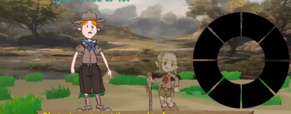
It has some serious problems but you could definitely do better