#archived-shaders
1 messages · Page 194 of 1
tiling looks simpler https://community.playstarbound.com/threads/waterfall-tilesheet-w-animation.132102/
Hi everyone! I've been working on making my own maps and stuff and have been trying to make them look good and balanced for multiplayer use. One...
ah i see , didn't know what sprite shape is
making tiles as in art is not simpler
u draw?
made tiles sets?
i make the art 😄
n i will tell you making tiles are huge pain
most likely u will need to make your own sprite shape renderer - or you can make a custom shader for the fill material and give it a mask texture for where to animate the water
either way it sound like it will take much longer then using tiles
or actually just add another layer on top
u can sort 2d sprites in the Z axis
draw water on a separate layer and give it a custom shader
u can use this [ https://www.youtube.com/watch?v=jBmBb-je4Lg ] it looks like it will do fine in 2d as well
i love that channel
i am learning from him actually this shader and all that
he is the best for vfx and shaders
https://gyazo.com/f91b6b26f3b41401a5e34908fe64f306 how do i get around this weirdness?

This is URP Lit shader
Use a Transparent Cutout material
Hey vertx! Thanks, but i already figured it out 😎
how to use view direction to make a hole in the texture ?
@sly breach can you be more specific? What are you trying to do?
given a direction angle i want to cut a whole inside a spheres
was thinking that making a whole in the texture and setting the alpha would do the trick*
so something like this

but when i apply this to a material its broken

ah nvm , the UV's are bad
here is what it should look like with valid uv's


How can I disintegrate a custom mesh? I am using these nodes to step through a random noise and plugging the result into the alpha. On a normal object like a cube or sphere, it would dissolve the object as intended. On my custom mesh though, it simply does nothing.

your object must be broke
try see if there are any UV's or not
How do I make a UV? I just made a model with primitives in Wings 3D.
that would be best to ask somewhere relevant to Wings-3D
i know in blender its fairly simple , and there are quite a few tutorials on YT
My computer can't run Blender.
Hey folks, I'm trying to find a simple way to swap colors for a sprite (not the entire sprite color, but specific parts so that they can change skin color, clothes, etc.)
Found this tutorial which is the closest thing I can find but it references project files that are no longer accessible.
It mentions this specifically:
"We'll implement this idea by modifying an existing sprite shader. Since the demo project is made in Unity, I'll use the default Unity sprite shader.
All the default shader does (that is relevant to this tutorial) is sample the color from the main texture atlas and multiply that color by a vertex color to change the tint. The resulting color is then multiplied by the alpha, to make the sprite darker at lower opacities."
Can I locate this myself somewhere in the project? I tried creating an Unlit Shader but it didn't seem to work correctly. Any guidance here is appreciated.
Game Development Envato Tuts+
In this tutorial, we'll create a simple color swapping shader that can recolor sprites on the fly. The shader makes it much easier to add variety to a game, allows the player to customise their...
Or if there are any alternative methods that people can recommend, would love to hear those as well
how do we deal with trails that are directed directly at camera and looking like this?

Does anyone know how to convert a shader from ShaderToy to Unity?
I followed this video, but haven't gotten the result I wanted since I just got started today
https://www.youtube.com/watch?v=CzORVWFvZ28&ab_channel=TheArtofCode

Twitter: @The_ArtOfCode
Facebook: https://www.facebook.com/groups/theartofcode/
Patreon: https://www.patreon.com/TheArtOfCode
PayPal Donation: https://paypal.me/theartofcode
Ever wondered how to get a shader from ShaderToy imported into Unity? Well wonder no longer because in this video I will explain how to do it. Its really not that hard.
Ru...
https://www.shadertoy.com/view/wdjSRc#
the Shadertoy I have been trying to get working
This is what happens when I tried to get it working myself

Tried to get it working, but I don't know what is wrong with it

I heard about static, but I tried it and feels like its not fixing anything before I just remake another one
i would try returning the different variables in both your unity shader and the shadertoy to work out what's different
Hi! I haven't really done anything with shaders before and just been using the standard shader and materials in previous projects, so I don't fully yet understand what's possible to do, but here it goes:
I have created a model in Blender that I wish to use in my Unity project. In Blender I am using a mix shader to transition from one material to another as seen in the picture - dirt ground to stone wall. I was wondering if it's possible to recreate this in Unity using Shader Graph, and if it is - if anyone could point me to some resources on how to blend two materials like this? I'm on 2020.2.4 btw and using URP for this project.

Do you need the blend to be procedural and adjustable via a mask or not?
Any recommendations on how I could convert this to a material that I can apply to single sprites rather than an image effect?
using UnityEngine;

[ExecuteInEditMode]
public class PaletteSwapMatrix : MonoBehaviour
{
    public Color Color0;
    public Color Color1;
    public Color Color2;
    public Color Color3;

    Material _mat;

    void OnEnable() {
        Shader shader = Shader.Find("Hidden/PaletteSwapMatrix");
        if (_mat == null) _mat = new Material(shader);
    }

    void OnDisable() {
        if (_mat != null) DestroyImmediate(_mat);
    }

    void OnRenderImage(RenderTexture src, RenderTexture dst) {
        _mat.SetMatrix("_ColorMatrix", ColorMatrix);
        Graphics.Blit(src, dst, _mat);
    }

    Matrix4x4 ColorMatrix {
        get
        {
            Matrix4x4 mat = new Matrix4x4();
            mat.SetRow(0, ColorToVec(Color0));
            mat.SetRow(1, ColorToVec(Color1));
            mat.SetRow(2, ColorToVec(Color2));
            mat.SetRow(3, ColorToVec(Color3));
            return mat;
        }
    }

    Vector4 ColorToVec(Color color) {
        return new Vector4(color.r, color.g, color.b, color.a);
    }
}
// Upgrade NOTE: replaced 'mul(UNITY_MATRIX_MVP,*)' with 'UnityObjectToClipPos(*)'

Shader "Hidden/PaletteSwapMatrix"
{
    Properties
    {
    _MainTex ("Texture", 2D) = "white" {}
    }
    SubShader
    {
    Cull Off ZWrite Off ZTest Always

        Pass
    {
        CGPROGRAM
        #pragma vertex vert
        #pragma fragment frag

        #include "UnityCG.cginc"

            struct appdata
        {
        float4 vertex : POSITION;
        float2 uv : TEXCOORD0;
        };

            struct v2f
        {
        float4 vertex : SV_POSITION;
        float2 uv : TEXCOORD0;
        };

        v2f vert (appdata v)
        {
        v2f o;
        o.vertex = UnityObjectToClipPos(v.vertex);
        o.uv = v.uv;
        return o;
        }

          sampler2D _MainTex;
        half4x4 _ColorMatrix;

        fixed4 frag (v2f i) : SV_Target
        {
        fixed x = tex2D(_MainTex, i.uv).r;
        return _ColorMatrix[x * 3];
        }

        ENDCG
    }
    }
}
Here's the shader itself. Sorry for the wall of text
If possible, but nothing really is a requirement.
I'd start by finding a sprite shader you want to use as the base. Sprite shaders are usually pretty simple, but the default sprite shader has some special features.
@low lichen Makes sense.. Though finding a sprite shader so far has been tricky for some reason
Perhaps I'm not looking in the right places
All the built-in shaders are hosted here
https://github.com/TwoTailsGames/Unity-Built-in-Shaders

GitHub
Unity Built in Shaders. Contribute to TwoTailsGames/Unity-Built-in-Shaders development by creating an account on GitHub.
The default sprite shader is here
https://github.com/TwoTailsGames/Unity-Built-in-Shaders/blob/master/DefaultResourcesExtra/Sprites-Default.shader
@low lichen Awesome, thank you. I guess the big question for me is in the script that has OnRenderImage, would I replace that function with a material equivalent? Or would I just remove it entirely because it doesn't apply in this situation?
@karmic delta You wouldn't need it, you would just need the shader and use that shader on the sprites you want
Gotcha. I think the script is mainly to choose the colors being used but I'll mess around with it tomorrow and see how it turns out. Appreciate the assistance.
Hey guys,
Any ideas how I can fix holes in a vertex displacement shader in shader graph?

Fix : don't make holes
Im trying to get the Darken Layer Mode and found this https://github.com/penandlim/JL-s-Unity-Blend-Modes but im having some trouble understanding how to use it

GitHub
👾 Collection of Unity shaders that support blend modes like photoshop layer style (Darken, Multiply, Linear Burn, etc) - penandlim/JL-s-Unity-Blend-Modes

whats its supposed to look like
Sorry if it seems dumb, but that's the bare truth. When displacing, the only way to not have holes, is to not make them. Usually, you have holes because you're displacing along normals, and your mesh has edge seams : avoid edge seams or don't displace along normals.
what it looks like atm

i know very little about shaders so im prob doing something wrong :c
Are you using HDRP/URP or the built-in renderer ?
Look if there is something assigned in "render pipeline" in the graphics sections of the project settings
i think so

Yep, so those shaders use a feature that is no longer supported with the new render pipelines to achieve the blending effect.
No
or even a way to make my own darken shader?
It's wouldn't work the same
But why don't you "bake" the final color of the sprites/images in photoshop instead of relying on real time blending ?
can we view build in sub graphs ?
I think so. But all nodes are not subgraphs
Well, if it's only on on of the objects (the menu block ?), you could do the same with shadergraph. Use the scene color node and the blend node
But it won't work if you try to stack multiple objects with the complex blend mode.
view docs : Out = pow((1.0 - saturate(dot(normalize(Normal), normalize(ViewDir)))), Power);
so something like this wouldnt work?

with the balls being a particle efffect
only the menu block/ bottons have the layer effect
the balls / bgm are normal
You could also use the blending mode of the unlit shader when set to transparent : https://docs.unity3d.com/Packages/com.unity.render-pipelines.universal@10.4/manual/unlit-shader.html
what does saturate( ... ) do ?
It's like clamp, but between 0 and 1
doesn't clamp can also do the same ?
clamp( value , 0, 1 )
so its similar to Mathf.Clamp01( ... ) ?
im not sure what that means, im a real noob atm. Ill try the shader graph rn tho
@amber saffron sorry to bug u, but can u look at my question above ? #archived-shaders message
What is the issue there ? With the disk mask ? You've answered yourself that with proper UVs it works. Is it about the fresnel ?

Does this object have smooth normals between the polygons ?
it this more or less the right track? Im not sure what to put for the other texture

is it possible to take whatever material its assigned to?
i don't think it does , just flipped normal's of a sphere in blender - gonna check out what are smooth normals in blender
That's probably the issue then, if the normals are not smooth, the fresnel will look blocky
Yes, right track 🙂
The master node needs to be set to transparent, and you need to add a texture property with reference name _MainTex to retrieve the sprite's texture. Sample it and plug it in the second entry of the blend node.
ty so much for helping me  , i believe i set the master node to transparent (from opaque in the settings of it) i dont know how to add a texture property
nor how to sample it
Look at the property pannel on the left.
And search for "Sample Texture 2D" node


Yep, should be good.
ok dope, so I just make that a material and assign it to the menu thing
Also, enable "opaque texture" in the renderpipeline asset : https://docs.unity3d.com/Packages/com.unity.render-pipelines.universal@10.4/manual/universalrp-asset.html

why can't i make pbr graphs in unity 2020.3.0f1
The master nodes have changed to the "master stack" in this version. You cen configure multiple outputs for the shadergraph in the graph inspector (top right) window
Don't forget to connect the A (alpha => transparency) from the sample node tot the alpha output.
Are you sure you've enabled the "opaque texture" on the good URP asset (there are multiple ones in the template project)
So say I wanted to make a node into a PBR shader< would I just use a blank shader graph?
iirc, the name is "URP/Lit"

Is this the asset that is assigned in the graphic settings, and/or in the current used quality level ?
i think i did the connect the A to transparency (prob not) and I didnt install the urp so I dont know anything about it, but i think this is the right one to do
I have no idea
also is that what you ment by connect the alpha to the output?
when i click on urp in the project settings that is where it sends me to
Also check in the quality settings. It is possible to assign a different asset for each quality level, and it will overide the one of the graphic settings
oh ok

so it wasnt using the urp
but I selected the same one i think
still black tho
You did click on "save" in the shadergraph window ? The shader will only compile if you do this.
Else, I don't see what is missing on top of my head.
.... i did not

its still not the desired effect im afraid
but its visible this time
wait I just realised the scene background is like the sunset thing
and not the purple image
im bad at this lol


Does someone understand, what's causing the pixel inaccuracies?
the right sprite is using my MaskTintShader


and this is my player and mask sprite
as you can see the right sprite has weird outlines and pixel accuracies at some places
Just think about the colors as values between 0-1 in every channel.
And then regular multiplication.
oh wait
I just removed one Multiply Node

the mid one was causing weird double multiplier
thats why the dark parts of the hood were way too dark
👍
fixed almost all of the issues
Nice job. 🙂

That could be your import settings having to be Point.
just for the mask?
For both I think.

Hmmm.
since its vector art and it stands and falls with AA
even though I didnt get AA to really work yet
It's not really Vector art when it's imported to Unity.
without filter for scaling its odd
yea
but unity still does a bit of filtering which makes it look more high res
Mhm.
point is just for pixel art iirc
It is.
hmm

after testing it, it seems to work fine, just ignores the purple image and blends with the true background. But because there isnt a true background the game scene just appears as normal
That's basically what Unity does when importing your asset when it's not point. And if it's different images you might imagine it decides on different pixels to get tesselated etc, in more complex pixel grids.
But yeah, that said..
I don't really know the solution here. You'll have to google-fu it out.
yea
I just found out, that I can only tweak hue and saturation
the value is untweakable
gotta figure out a different tint path
Multiply the mask value by another float value.


Which is your "Value"
I meant HSV
Aha.
if the value goes any lower than 100 it almost instantly causes the darker parts of the hood to turn black
I guess since it already is a bit grey, so it multiplies it all the way up
That's right. 🙂
If you want to tint different parts different colors, you have to have different masks per piece.
but I want to tint the whole hood in one color
just a bit darker variation at some parts
Id have to add a Branch Node I guess?
oh well its a connected sprite
yea no
the only way is to make the whole hood white and use two masks I guess
Yeah, if it's white you'll be setting the color instead of tinting, which is a lot easier.
Ah.
Your "Outline" is brown, no?
then Id need to have a different mask for every color shade
Instead of black.
black
Okie.
The darker parts should just have a darker value of whatever tint you multiplied by.
just for 2 parts with the same color (just in different shades)
I heard Texture Sampling is bad for performance
so I dont think 5 Texture Samples for 2 tints is that good
You can't really make performance judgments in a vacuum like that.
It depends on the context: Are you going to have a lot of these sprites?
Like.. Hundreds?
yea but to achieve this I'd need 2 masks for the clothes
We're not working with 1KB of memory anymore fortunately. 😉
I guess I can change up things later if I am going to use it quite often
so I need 2 masks?
Well, not really..?
You're saying your issue is..
If you put the value at say.. 0.8.
Your dark grey parts, that are of value 0.2 get too dark?
black yes
If you have.. 100% green.
ohh
And you multiply that by your sprite's color. Which in that part is grey.
I get your point
so for the darker stuff Im only applying 80% of the tints color
Yeah.
so it doesnt multiply a dark color with something dark
Just think about them as floats that are multiplied together.
And think of the value it ends up with.
It's easier that way.

What you are doing is you are multiplying a value, 0.2,0.2,0.2 by like.. 1,0,0 for RED. right.
So you're multiplying the first 0.2 by 1.. So that's .. 0.2
Then the other two by 0.
So those will be 0.
You end up with 0.2,0,0.
yea
So a little bit green.
for white that's no issue, but for something which is already colored..
Yeah that gets funky.
You should be using greyscale for the parts of your sprite you want to tint.
I thought I am?

yea but its colored grey
thats what I meant. my bad
yea
so I need to tweak the tint color value?
before multiplying it

its cuz Im using add
Haha, yeah. 😛
My goal is just to get you to really internalize what's happening to your values.
That way you can debug your stuff yourself.
Go through it step by step in your head, imagine what's happening to your values.
Fiddling around with multiplication orders and stuff randomly is a fools game. 😄
everything which is on the mask
That's what the mask multiplication does.
Value is 0 where it's black.
1 where it's white.
yea now the multiply part looks fine
Mask * ColorTint * SpriteColor

Great.

Yeah I don't know what you're trying to achieve there.
Yeah, always just go through it step by step and have a clear image of what you want to achieve.
When you go into like a "Try random shit" mode, you're just gonna get lost and frustrated.
Simplify the issue.
since its just putting the sprite over the masked out, painted part
then I get something bigger than 1
And that's not correct, is it?
no
combine? Oo
You have a color, right?
yes
And you want to apply that color to your sprint.
Sprite*
Just think about getting that done first.


Ok, cool. Now you have this black stuff that you want to use as alpha.
I just have to bring the non tinted, masked out and masked out stuff together again
If you subtract by the color, then you subtract the white.
So that's not correct.
You want to subtract the black.
so by the alpha
yea..
So how do you flip your mask?
Is there any way I can clamp this so the effect fades out near the edges? I tried blending a mask on top but when I convert the data into Normal using Height from Normal, it doesn't take the mask into account for some reason.

The setup to produce the rings look like this
there is something called Invert Colors
wouldnt the One Minus node work?
ohh
But yeah, you want to have a texture that has an alpha where the black is your alpha.
Then multiply that texture with your sprite's texture.

You actually don't need to, nope.

Working as intended.

Nice.

The white outlines?
yea
It's not that odd.
ik the Tesselation is what's causing it

: \
But actually.
How did you make your mask?
Did you just marque-select and invert and delete?
Because that'll be quite inaccurate anyway.
I took the parts I want to tint, colored em all white and deleted the rest
Okays. 🙂
would you do it differently to prevent such white outlines?
I see
this is for whenever you hit the tree to harvest it
but besides the small white outlines it turned out amazing!
thank you for your time and patience 🙂
my first day of using Shaders
just read about it a bit before

I set the color format, so there is no compression to set
and max size is set as high as the sprite is big
all sprites are a multiple of 4
Just try to set your filtering to point to see if that fixes your issue.
Though your art probably has tessellation built in.
Put point on both your sprite and your mask.

I still see tessellation. So your art has it built in.
Which is causing inaccuracies.

yea
Yeah, you can just try that for now.
If you can export with point.
it would fix it?
Well, that means you'll definitely have a 1-1 mapping between your mask and your sprite.

Nearest Neighbour
and I set the filter to point in unity?

Just inspect your sprite after export.
this is what nearest neighbour looks like
:\
yea :/
Well that's quite shite.
. _ .
I don't work with vector software, so I'm not sure how you set it to not smooth your edges.
So.. Google that I guess.
I think i fixed the normals but im having trouble controlling the radius of the effect proportional to the screen height , here is the effect at scale 3

and here is the same effect with the same shader parameters at scale 10
( where scale is the transform of the 3d model )
return what?
its basically 2 shader values that stay the same ( pow is the node input , strength is the output multiplayer )
it seems that no matter the scale value nor the power values there always will be some an anomaly at the origin ... not sure what is going on
placing the camera directly in the middle of the sphere will always have this massive gap and won't render anything no matter how large is the pow
It's hard to find the message again, but can you post the current state of the graph ?
if this is the wrong place to ask this, lemme know and ill remove it, but is there anything online that can show me how to store parts of a mesh into an octree as data? I am trying to make an octree, but I cant figure out for the life of me how to store the meshes data in it as well(coded in C#)
I also want to be able to send it all to a compute shader to accellerate my ray tracing cuz rn it runs very very badly(custom)
i have a modified fresnel node that i feed to the shader alpha value , but the default fresnel has the exact same issue , i think its due to the spherical shape of the object and the dot product of the normals ( ? )

I wonder what's happening here. Maybe a float precision issue 🤔
don't think so , but ill try changing all the nodes to half or single , here is another clip of what seems to be off - the closer the camera is to the center of the sphere the bigger the hole , note that the grid stays the same size
i fixed it , the normal vector needed to be of a tangent space

woop
So, you wanted a "round" mask at the center of the screen ?
yea lol
Why not simply using screen space coordinates and draw a disk then ?
because in VR static overlays are bad
if u move your head around inside this sphere - spacial awareness will be preserved
plus i also have a cool way for making cockpits 💯
okay
Are there any resources or anything that I can look at for examples as to how to store mesh data in an octree or construct a different BVH and store mesh data in it in C#, to then pass to a compute shader? I am trying to accellerate a ray tracer but I am struggling with accelleration structure implementation and sending it to the compute shader
If this doesnt belong here, tell me and ill remove it
+1
Hey guys, small question. Is there a way to tell the shader after 2500 renderqueue to draw on the _CameraOpaqueTexture?
Shader "Sprites/PaletteSwap"
{
    Properties
    {
        _MainTex ("Sprite Texture", 2D) = "white" {}
    }

    SubShader
    {
        Cull Off
        ZWrite Off
        ZTest Always

        Pass
        {
        CGPROGRAM
            #pragma vertex vert
            #pragma fragment frag
            #pragma target 2.0
            #include "UnitySprites.cginc"

            struct appdata
            {
              float4 vertex : POSITION;
              float2 uv : TEXCOORD0;
            };

            struct v2f
            {
              float4 vertex : SV_POSITION;
              float2 uv : TEXCOORD0;
            };

            v2f vert (appdata v)
            {
              v2f o;
              o.vertex = UnityObjectToClipPos(v.vertex);
              o.uv = v.uv;
              return o;
            }

            sampler2D _MainTex;
            half4x4 _ColorMatrix;

            fixed4 frag (v2f i) : SV_Target
            {
              fixed x = tex2D(_MainTex, i.uv).r;
              return _ColorMatrix[x * 3];
            }
        ENDCG
        }
    }
}
Can anyone tell me why I'm getting a "redefinition of 'v2f'" error?
If you look at the source code for UnitySprites.cginc, it already contains a struct named v2f. https://github.com/TwoTailsGames/Unity-Built-in-Shaders/blob/master/CGIncludes/UnitySprites.cginc (line41)
Either use theirs, or rename your one to something else, or if you don't need the include, remove it.
I want to outline my teleportable area mesh. How can I do that? I'm using a shader graph
Guys, when can i buy amplify shader with a discount ?
so im using this asset in my project(which i recently upgraded to urp) but the grass turns out to be invisible when i use it or view it in its folder

things I tried: upgraded materials to urp
reimported them once
but the grass is still invisible
When you move to urp, shaders have to be made in hlsl or shader graph, standard built in cginc won't cut it
Hey guys, anyone has any insights why I could be getting these weird transparent squares pattern in my material?
@sly breach That IS a super cool effect at least.
The scale 10 one looks like it could totally be used as a stylized transition, like the sort of stuff you'd see in a persona game

looks a bit like z-fighting / depth issue, is the shader transparent or opaque alpha clip?
if transparent are you forcing it to write to depth etc?
So how do I change to the right thing?
@bright flicker There's a LOT going on there; many different effects. I suggest trying to break it down into the individual elements to tackle.
I'm new to shaders, whats the line of thought?
Well, the first thing to look into would be the outlines; there are several ways to do those. After that I'd look into colored shadows and screen overlay textures.
can it be done in shader graph?
A lot of the look of it will come down to the models and textures rather than the shaders.
And partially shadergraph, partly render features.
Unity has an official tutorial on outline rendering with render features
Though googling will probably find nicer
someone broke the effect down for me "It’s a sobel -outline post process with a gentle parchment paper multiple overlay"
For geometry like this you could probably also just draw the lines on the textures of the model
doing it as a PP effect would save me time I think
hm cant find anything about screen overlays in shader graph, Im guessing its a render feature?
If you just need a static overlay, you can just add a transparent plane in front of the camera too
That's how I do ovscreen textures for 2d stuff
when buying assets from the store, one needs to ensure that it will support the relevant render which one is working with. In this case URP, if it does not state compatible with URP or HDRP it's safe to assume that it's only for use with built-in. Unless you are proficient in writing shaders, there is no "upgrade" as the shader needs adjusting to support URP.
You could reach out to the asset store developer to see if they have / will make an URP compatible shader for this product or ask for a refund as you didn't realize it was not suitable for your project.
As this asset claims only URP product it should work, if it's not then again I would advise reaching out to the dev for help. But as it's free I would not expect a speedy response but you never know unless you try.
is it possible in shader graph to clamp the lighting strength?
Hey question when i am changing to multiview from multi pass in android seems that some of the shaders will stop working any idea why?
how do I make my shader affect only darker areas of my screen?
Hey guys, I'm kinda blocked trying to figure out the requirements to get additionnal lights informations
void AdditionalLights_half(half3 SpecColor, half Smoothness, half3 WorldPosition, half3 WorldNormal, half3 WorldView, out half3 Diffuse, out half3 Specular)
{
    half3 diffuseColor = 0;
    half3 specularColor = 0;

#ifndef SHADERGRAPH_PREVIEW
    Smoothness = exp2(10 * Smoothness + 1);
    WorldNormal = normalize(WorldNormal);
    WorldView = SafeNormalize(WorldView);
    int pixelLightCount = GetAdditionalLightsCount();
    diffuseColor = half3(pixelLightCount * 100, 0, 0);
    for (int i = 0; i < pixelLightCount; ++i)
    {
        Light light = GetAdditionalLight(i, WorldPosition);
        half3 attenuatedLightColor = light.color * (light.distanceAttenuation * light.shadowAttenuation);
        diffuseColor += LightingLambert(attenuatedLightColor, light.direction, WorldNormal);
        specularColor += LightingSpecular(attenuatedLightColor, light.direction, WorldNormal, WorldView, half4(SpecColor, 0), Smoothness);
    }
#endif

    Diffuse = diffuseColor;
    Specular = specularColor;
}

#endif
This code works fine called as a custom function from the shader graph. But I don't know what I'm missing to get it work with hard coded shader. I guess I didn't enable the filling of the variables used inside, but hard to guess how to do so.
Usually you also need to define some keywords
#pragma multi_compile _ _ADDITIONAL_LIGHTS_VERTEX _ADDITIONAL_LIGHTS
#pragma multi_compile_fragment _ _ADDITIONAL_LIGHT_SHADOWS
You should also be including Lighting.hlsl if you aren't already.
#include "Packages/com.unity.render-pipelines.universal/ShaderLibrary/Lighting.hlsl"
Yeap looks like I forgot those little guys 😄 the count doesn't seems empty anymore. Don't really know how to use it correctly but that's a first step.
Thanks
Does anyone know why editing _BumpScale is disabled on mobile platforms in Unity's SRP?
Does anyone know why uncommenting this line causes unity to freeze?
float4 neighbourTex = (0,0,0,1);

                    for(int x = -0.01f; x < 0.01f; x+= 0.01f)
                    {
                        for(int y = -0.01f; y < 0.01f; y+= 0.01f)
                        {
                            if(i.uv.x + x < 0 || i.uv.x + x > 1 || i.uv.y + y < 0 || i.uv.y + y > 1 || x == 0 || y ==0)
                                continue;

                            neighbourTex += tex2D(_MainTex, float2(i.uv.x + x, i.uv.y + y));
                        }
                    }

                    //return neighbourTex / neighbourTex.w;
                    return renderTex;
Sorry for the poor formatting, I'm on mobile
🤔

why are you using int
does this even compile?
the resulting equivalent when all the casting and converting is done is probably like:
for (int i = -1, i < 0; i += 0)
which obviously will be an infinite loop
Makes sense. And I guess that because the return line is commented the precompiler just strips all the loops code because it's unecessary.
can somebody explain the intuition behind this one

why does it results in hollow shapes ?
Hello again ! Someone know how to get unity sky color in urp shader? In fact I wasn't even able to use the shadergraph node. I guess I miss some define : s
sky box can be a shader , what do you mean get its color ?
SHADERGRAPH_AMBIENT_SKY unity_AmbientSky those macro/variables are supposed to give the color used by the sky of the skybox, if I'm right
that's stressing me that you cut out the value range of the remap x) probably won't explain... but
-10 , 10 lol
u can add custom nodes and have inline functions
idk what is going on there but maybe this will help
I'm not using shader graph on this one, but even the shader graph node for this doesn't work for me
void Unity_Rectangle_float(float2 UV, float Width, float Height, out float Out)
{
    float2 d = abs(UV * 2 - 1) - float2(Width, Height);
    d = 1 - d / fwidth(d);
    Out = saturate(min(d.x, d.y));
}
I always forgot what do the fwidth, but yeah there is at least an abs
but if the outcome is less that the next value, that can happen
The logic is a little strange as the remap output is a Vector1 while the UV is a Vector2. Both components are filled with the same value. Usually you'd use the UV node which places a rectange centered at (0.5,0.5) with the given width/height. A width/height of 1 would fill that 0-1 UV square, but you can still input coordinates outside that range, which would be outside that rectangle. The hollow shapes is due to the coordinates being outside that rectangle, though it doesn't look anything like a rectangle due to the coordinates being used.
If you're doing ambient lighting it's usually baked in with the lightmap or lightprobes data so you don't usually access the colours directly. You should use the function,
SAMPLE_GI(input.lightmapUV, input.vertexSH, inputData.normalWS);
along with something like this in the vertex shader
OUTPUT_LIGHTMAP_UV(input.lightmapUV, unity_LightmapST, output.lightmapUV);
OUTPUT_SH(output.normalWS.xyz, output.vertexSH);
The source for the URP/Lit shader (LitForwardPass.hlsl) should show how it's set up. https://github.com/Unity-Technologies/Graphics/blob/master/com.unity.render-pipelines.universal/Shaders/LitForwardPass.hlsl
Ahah just put my eyes on it at this exact moment x)
Thanks I'm sure I'm on the right part then ^^
But I'm curious if someone know how to make the node in the shader graph work then :0
It returns unity_AmbientSky/unity_AmbientEquator/unity_AmbientGround as you mentioned above. I think the node has been a bit glitchy in the past. I seem to remember it only updates when the game starts or something like that?
I don't really use it that often so not sure if that's changed. There's a GI node too which includes the ambient lighting so I'm not really sure why the others are needed, maybe for a cheaper version, idk.
On game start or scene save, the documentation said. But didn't work for me 🤷
im a bit perplexed about this part

( this is Unity_Rectangle_float recreated in nodes )
It's basically creating an anti-aliased version of the shape. If you used a Step node it would be similar results but much sharper/pixellated. The fwidth function is also the same thing as the DDXY node.
What fwidth/DDXY does it a bit more complicated, but in short it's comparing neighbouring pixels/fragments as the shader runs in 2x2 pixel blocks. If I recall correctly ddxy = abs(ddx) + abs(ddy)
here is what it looks like with the remapped -10 to +10 UV coordinates - already at the absolute stage it looks like something i would need

where would u put the step to compare ?
looks totally different on the nodes if i do this

after the Subtract node, probably with an Edge value of 0. And I mean compared to the preview on the Divide, not the custom function
still doesn't look anything like fwidth
sounds like a convolution operation
ddx = x1 - x0 ?
I think you confused the nodes I mentioned. fwidth is the same as the DDXY node.
I think so yeah
ah yes it is

You can also try looking up "screenspace partial derivatives" if you want to know more about them.
now it makes a bit more sense , its not very intuitive when the preview nodes will only draw value from 0 to 1

but preview nodes are absolutely amazing as they are already
@regal stag any change you know extensions for preview nodes to change the draw range / color space ?
Bruh I'm a dumb. It's bc I was using ints prior to changing it, and I'm so used to using car that it never even occurred
var*
No, but that's basically what the remap is for. Could use that temporarily to remap values into a different range.
This is what I meant by the comparison with the step node btw. Can see the anti-aliasing being produced by fwidth/ddxy better with the ellipse too.

is there a way to make a texture be the same "size" independent of the size of the object/face?

That's the same material on 2 different objects. Is there a way to have the squares on the texture have the same size on every object that uses the material?
while also avoiding having it be "squished" on narrow surfaces

may have found the answer https://gamedev.stackexchange.com/questions/111060/unity-tiling-of-a-material-independen-of-its-size

Game Development Stack Exchange
I am using Textures and Materials to tile my sprites, for instance when building a wall in my game.
The problem with this is that everytime I resize the plane or size of my game object I have to r...
What you want is a world aligned / triplanar projected texture
i'll look into that
Wondering if anyone can help me adapting this screen space rain impact system to work in URP. I managed to add a custom renderer feature for depth normals but a bit lost on where to go next. https://github.com/thnewlands/unity-botw-screenspace-rain

GitHub
A study of screenspace rain impacts in Breath of the Wild - thnewlands/unity-botw-screenspace-rain
Maybe there's an easier way to achieve these results? My goal is to get rain impact splashes without using collisions in URP (I'm using an ortho camera)
how to overlay two nodes ?
so that both colors will be preserved

add will work pretty good if the top one is pure white

Use a Lerp or Blend node (Overwrite mode). Set A/Base to your 1st layer. Set B/Blend to the ColorA. T/Opacity to the black/white output before your 2nd layer.
already tried those 2

the red doesn't pop up
Because you set the Opacity to 0.5. It's an interpolation, if you set it to 0.5, you'll get a colour halfway between red and blue. You need to set it to 1 where you want the red to show up, and 0 everywhere else to show the blue/black. That's what the black/white preview before your 2nd layer is.
i mean like this
to keep both colors , overlay the red on top of the blue ( the blue is thicker , the red is skinny )
in theory this should do the trick _blue_node - float( _red_node ) + _red_node
but it doesn't :<

@sly breach This is what you want right?

Or maybe the red mask is a bit centered but should still get the point across
never thought about using a texture as the lerp value before
thank you
How do you change the UV tiling of Shaderlab shaders?
Feed a sampler state into the ss input if appropriate nodes
Is there a way to make a 2d sprite reflective like a mirror?
If you have a separate mask sprite to separate where you want the reflections, and a normal map then i don’t see why not, sprites are inherently just textured planes
i cant find the master node/stack in shader graph
oh im stupid
i wasnt using the urp thingy
Just make your boxes with probuilder. It will automatically tile the UVs for you and you can use a regular shader
when I make a material off the shader and add it to an object, it doesn't change anything

despite it showing both the texture and the waves working in the preview
Does anyone know if this situation with shadergraph has improved at all recently? I really want to upgrade my project to HDRP and use shadergraph but my game relies heavily on compute shaders and being able to read data from StructuredBuffers in my shaders.
https://forum.unity.com/threads/is-shader-graph-support-compute-buffer.753701/
Unity Forum
I want to use shader graph,but some data come from compute buffer. I often use instance render, custom compute buffer.
Thanks in advance.
If not - does anyone have any experience hand-writing shaders in HDRP and do you know if it supports StructuredBuffers etc?
@proud hamlet World space UVs, usually with triplanar mapping.
is there a method for auto tiling using object scale for cubes ?
this seems to work on 2 axis only when y scale is 1

was thinking something todo with normals but not sure how yet
You want triplanar mapping.
first time hearing this
Uv is inherently 2d, object/workd coordinates are 3d. So if you feed x and y into uv, it will output the sane value for all z levels... the same no matter which 2 you pick, the other axis wont cooperate
Triplanar takes the normal of the surface, and 3 sets of uv mapping, then blends between each depending on normal
to know what axis to map the UV to , or am i wrong ?
why 3 sets ?
can't we just flip the X&Y domains based on the normal ?
There is a triplanar node that will map a single texture across all 3 axis properly, but if you want different textures (commonly to put grass on top of hills, and dirt on the sides) you have to use code or rebuild the function in nodes
oh i get it , so it would be possible to have a unique texture per axis ?
i see
what's the name of the node ?
Triplanar mapping, i think under UV... but just type in triplanar and it’ll find it.
This is Cyan’s tutorial on it
This post includes an introduction to using the Position node to sample textures rather than using mesh UV channels, which is also the basis of Triplanar mapping. It won’t be super in-depth but wil…
cyan 🙌
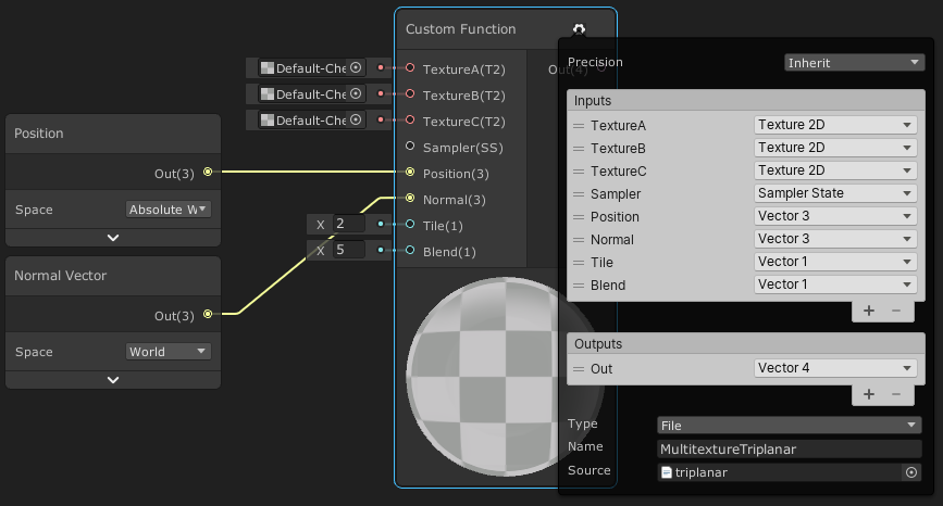
This is triplanar built in nodes, not SUPER complicated just make sure you match all the settings

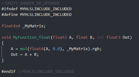
If your not using a (t2) texture input, you have to build it out in nodes, thats just the nature of the builtin function. Or use a custom node and copy the code in
yea i found the docs page , might try custom function , seems like it will be a lot of nodes
float3 Node_UV = Position * Tile;
float3 Node_Blend = max(pow(abs(Normal), Blend), 0);
Node_Blend /= (Node_Blend.x + Node_Blend.y + Node_Blend.z ).xxx;
float3 Node_X = UnpackNormal(SAMPLE_TEXTURE2D(Texture, Sampler, Node_UV.zy));
float3 Node_Y = UnpackNormal(SAMPLE_TEXTURE2D(Texture, Sampler, Node_UV.xz));
float3 Node_Z = UnpackNormal(SAMPLE_TEXTURE2D(Texture, Sampler, Node_UV.xy));
Node_X = float3(Node_X.xy + Normal.zy, abs(Node_X.z) * Normal.x);
Node_Y = float3(Node_Y.xy + Normal.xz, abs(Node_Y.z) * Normal.y);
Node_Z = float3(Node_Z.xy + Normal.xy, abs(Node_Z.z) * Normal.z);
float4 Out = float4(normalize(Node_X.zyx * Node_Blend.x + Node_Y.xzy * Node_Blend.y + Node_Z.xyz * Node_Blend.z), 1);
float3x3 Node_Transform = float3x3(IN.WorldSpaceTangent, IN.WorldSpaceBiTangent, IN.WorldSpaceNormal);
Out.rgb = TransformWorldToTangent(Out.rgb, Node_Transform);
do i need UnpackNormal at all ?
im guessing .xxx = float3( x, x, x )
Im not familiar with the code version 🤔
https://docs.unity3d.com/Packages/com.unity.shadergraph@10.3/manual/Triplanar-Node.html
just for rereference
Im on break at work, i dont have time right now 😦
nah u r alright , thanks for any info at all
Np good luck
@hushed wing Although you probably already knew, the answer to my question about duplicating grass shader a few hundred times and then slapping it all over the terrain with a size of 1000, 600, 1000, was a definite no lol. Even with just with like 10% of the terrain covered and a few hundred enemies spawned and spread out, fps dips to 30s with an RTX 3080.
Although, I’ve never looked into performance things. There’s probably a way to do it with object culling.
does anyone know a solution to fixing unity not displaying a basic mesh as transparent when i change the layer to transparentFX?


finally got it working!
quick question
the water seems to move in tune with the movement of my mouse, when my mouse isnt moving, the water stops, and itll continue when i start moving my mouse again
is there a way to make it so it only moves when i start game
Thats a quirk of sceneview when the scene isnt in “play” mode. Run the scene and it should be fine
but changes made to the game during play mode arent preserved
No, unfortunately any change made in the inspector doesnt save when the scene is stopped, only things that do the i know are shadergraph changes, and c# changes (although recompiling the code mid run sometimes breaks stuff.
@teal solstice that dropdown only sets the layer, it doesn't affect the material or shader in any way. Layers are used by unity to tell what objects to render, which should collide with each other, etc.
I still can't believe that there's no way to designate values to be saved when you exit play mode all these years later
@lethal brook there is a button at the top of the scene view to enable animated materials, but even with it off you'll still see some animation while interacting with the window because you are forcing it to refresh.
Scriptable Objects are a good way to save stuff from play mode. If you expect the need, using them in your architecture makes it work
You can also copy values of a script in play mode then paste then in edit mode.
and in this case, Materials will also save
the time the shader uses to drive something like waves is different in edit vs play mode anyway
it will reset to 0 when you play
and the editor has its own time
Yes, it is, but just saying that's all that's happening.
Thiugh on that note, is there a way to have different render features on the editor window than the game?
It is getting really annoying to see camera relative effects smeared across my scene view.
not that I know of
So to make it render as transparent in game, a shader should do the trick? I was able to get it to render properly with that layer effect on other objects that I used to create game boundaries without using shaders, but I'll see if that fixes it
A transparent shader, yes
The editor uses the forward renderer assigned on the URP asset set as the default. You can have multiple and change it for your main camera so scene view vs game view uses a different forward renderer.
It seems like a weird oversight that you can't set the renderer directly, but thanks!
That's the version for normal maps. There's a separate albedo/colour code snippet on the page if you want that instead (both docs and my tutorial)
So, in URP there's a way to call CameraColorTexture to generate data to detect color discontinuities in the scene. I'm wondering if there's a way to generate this texture in built-in pipeline?
If it's for a mesh in the scene you'll probably want to look into GrabPass, it can generate a similar texture to the CameraColorTexture
If anyone uses custom functions in shader graph for lighting/shadows you might be familiar with the "shadowCoord" error that is produced in an Unlit Graph when using 1/No Cascades and the _MAIN_LIGHT_SHADOWS keyword (which is required to prevent Unity from stripping the shadow variants from the build).
Well, I just figured out you can fix it if you undefine this in your .hlsl file. Just wanted to share ~
#undef REQUIRES_VERTEX_SHADOW_COORD_INTERPOLATOR
Can also surround it in SHADERPASS checks if you want to be slightly safer to stop it removing the interpolator for the SHADERPASS_FORWARD pass which is used by the PBR/Lit graph if you use it there (which has the shadowCoord in Varyings so doesn't error, and is cheaper since it handles it per-vertex).
I've also updated my functions on github with this fix : https://github.com/Cyanilux/URP_ShaderGraphCustomLighting
this tutorial im following is telling me to use the albedo node
but i can't find one
If you're in v10+ the port was renamed to just "Base Color"
oh i see
when making a material from a shader, how do i make the tiling larger so that the water ripples arent so tiny

Use the tilling and offset node to controll the tiling of the UVs used to sample the texture
Thanks for sharing TriPlanar mapping. Spent several days trying to figure out how to combine HLSL shader code with Triplanar mapping.
soooo I made an octree thing to seperate a mesh into pieces(each leaf node of it has a list of numbers that represent what triangles are inside of it), and it seems to work ok(although initialization/building times for it are REALLY long for small meshes), but I build it via a recursive(I think?) octree, made from the tutorial from World of Zero youtube channel
My question is, how on earth do I send something like this to a compute shader? My goal for this was to use it as an acceleration structure for my raytracer(tho im starting to become more doubtful as to my implementations effectiveness, but idk what else to do/how else to do it)
As usual if this is the wrong place let me know and ill delete it, but idk what else to do with this
is it possible to make a square that has a fog effect inside it?
that way when you're underwater, theres fog that prevents you from seeing too far
everything is possible, its up to the programmer / artist everything is just manipulating numbers. its up to us to break down WHAT exactly we want to change about how the scene is displayed and why, then reversing that into how to do it in the tool were using, for your question you need to be able to detect is a given pixel being drawn is going through a volume or not, which is an easy volume check once your completely submerged. it will get interesting when your halfway in the water and can see both in and out, even many AAA games fail that use case
I meant the question more as in "how do i go about doing that"
the water surface is opaque
so i don't have to worry about seeing in/out of the water
then you need to lock down HOW you want the pixels to change based on the information in the scene. in water color information gets muted, the further something is, so not only does it fog out but the colors blend together, its why many fish have "red" camoflage, the way colors change with distance in water is unintuitive, this applies to general depth, but also distance away from camera horizontally, red fish literally disappear sooner than other colors.

i just want things to fade as they're far away, and i want water thats farther away to be a darker colour
the games artstyle is fairly simplistic so i don't need anything super crazy
you will want to bring in the depth shader information, and use that to process how much of a given objects color information to blend into the given pixel. so i think playing with depth shader information is going to give you wnat you want, atleast inside the shader. the most simplistic, is using the scene fog setting under Window>Rendering>Lighting>Environmental
You could compute that water-level intersection of the camera pos, then remember that and do a distance calc for all the water pixels. You'd get a circile/radius type of thing from that point. Pass it to the shader to do the distance calc. The greater the distance, the darker you'd make it.
Could you walk me through that if it's not too much trouble?
No problem if you don't feel like it
So you're not talking about making objects inside the water darker, just the water itself?
I want objects to fade as they're farther away, as in be covered by the water
i assumed making the water darker would make the objects appear darker
Does the camera ever go into the water?
yeah
its third person, the player will be able to dive underwater later in the game
If you just want a darkness level, check out LinearEyeDepth macro. I think you can get that as an output of the depth texture node. That MIGHT help. But if the camera height above/below water changes, then it won't be water-level relative to use those macros.
Otherwise, if you know the worldspace Y pos of the twater level use camera.x and Z worldpos, and water level Y pos and you can calc a distance function from there. You'll want object's worldpos too. Then distance(objectWP, waterlevelWP).


OK, "Scene depth" is flat, like you're seeing.
Is that what you want?
It's camera plane relative.
Not eye distance, which is different
scenedepth read into a gradient, mix in whatever other color data you want, i wanted to keep it simple for him to play with

yes that is the color fading i was talking about at first, the color an object is displayed as changes as it gets further away, closer to the waters color, same concept, just changing the colors on the reference gradient, there are many more complicated ways of calculating it depending on how deep down the rabbit hole you want to go
but notice how red goes away first, it helps sell the fact that its water and not just fog
I know this is very beginner stuff but I was trying to figure out how to do additive blending on 2D objects using shader graph
Wasn't sure whether to post this in 2D or here

https://docs.unity3d.com/Manual/SL-Blend.html
It's a Blend 0ne One oldschool.

What pipeline?
interesting shader topic 🙂
lol Cuz I'm stupid.
Is an SG function
You can set the blend mode for the shader too.
I'm not running SG right now. So sad
I don't understand where to write code for shaders. I'm very new to shaders
"code" code is in a custom shader node and is usually a more advanced topic, have you played with just shadergraph yet
I'm doing that but I'm not sure how to get additive blending out of it
this is breaking my brain, ill hold off on water fog for now
i should probably focus on above water stuff
considering thats 99% of the game
So my thought process is this much so far and I figured that Additive would be an available mode where it says Linear Light but it isn't

at the basic level your working with numbers. additive blending is adding 2 numbers together for each color, what two numbers are you wanting to add, the sprite color, and background scene color?
your image is adding a number to itself, so your basically multiplying each number by 2
I guess what I want is for sprites to have the additive effect amongst themselves
So if these sprites overlap, the effect is apparent
But how would I show that in shader graph?
One thing thats always puzzled me. Why do Console Shader error line numbers not correspond to actual line numbers in the shader code?
ie
Shader error in 'foo': invalid subscript 'xy' at line 41 (on d3d11)
but on line 41 I have commented code!
//_MainTex_ST.x=2;
Is there any "universal" way to create ground fissure that works for all render pipelines ? Every time I find something it works on only one pipeline. The ShaderMask in unity wiki doesn't work in URP (or you need to put the ground surface on "Transparent"), stencil buffer works in URP but as I understand it wont work in HDRP. Or you can use the ForwardRenderer in URP but then you need to use Layers, which I like to use only for physic stuff.
Or maybe there is a way to create this effect without using the render queue or anything like that. Like a magic shader ?
why is the water pink now
pollution?
The line probably corresponds to something in the compiled version of the shader, so isn't always useful.
there are ways to do this, it might take a combination of techniques... have you looked at interior mapping effects (aka fake rooms) https://www.habrador.com/tutorials/shaders/2-interior-mapping/
think I saw someone use a modified decal shader to do this sort of thing for ground fissures, but can't just spot it at moment
This is a tutorial on how to create advanced shaders in Unity. You will learn volume rendering, interior mapping, and much more. In this section you will learn about interior mapping, which is a technique used to simulate floors in buildings.
idk but it looks really cool
that's all i ended up needing , thanks

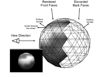
Noob rendering question: triangles with normals facing away from the camera are not rendered (they don't go all the way to rasterization), but they are passed to the GPU for culling? E.g., if I have a million triangles facing away from the camera, I'm not rendering them but there is some minor overhead associated with the culling process?
In visual terms this is how rendering works. The faces on the back of the sphere are not rendered so you could have an incredible amount of detail there (e.g., a character's face) without it having too much of a performance cost? https://flylib.com/books/2/124/1/html/2/files/figure15-6.jpeg

Anyone know where I can find a sample manually written shader for HDRP?
I want a basic Lit shader that I can modify the vertex pass of with some data from a compute shader
I'm at a dead end for increasing performance. I followed a Brackey's for creating a shader graph for grass movement. I then tried duplicating the grass/shader hundreds of times to place around in my scene, but the performance is abysmal. I've tried the basic performance tweaks, and I've even went as extreme to do layer culling specifically for the grass, but the only way to get the performance even reasonable is to apply linear fog and set the culling to like 15m, but with that much fog to hide the pop in you can't see anything.
Is there a better way to do this?
do you have gpu instancing turned on ?
Yeah I do @sly breach

I just don't think it's reasonable to cover this all with grass how I have it eh
u can always try Graphics.DrawMeshInstanced
Compressed the textures down to 32 also
Hm
Never heard of that. thanks.
I will have to read a lot into that to understand, but sounds like it would be better than what i'm currently doing.

one more think to keep in mind LOC would save u alot of trouble if you want to support very distant rendering range
gameobjects are very expensive in large quantities i would look into DOTS or try that DrawMeshInstanced trick
Ok good to know. Yeah I had a feeling this was wrong, felt too brute force to be effective.
Will look into DrawMesh.
And can you explain this? LOC? Lens occlusion culling, or?
sorry i meant LOD
last time i played with DrawMeshInstanced i was able to draw a million shapes easily , there are some assets on the store that remove the need to use code for this but i would still recommend trying it out as its not too difficult
@vernal glen just search for an example on github and this one seems pretty straight forward ( u can ignore batchRendererGroup ) : https://github.com/tkonexhh/Unity-Procedural-Terrain/blob/master/Assets/Scripts/DrawMesh.cs

GitHub
Contribute to tkonexhh/Unity-Procedural-Terrain development by creating an account on GitHub.
ok will see if i can figure it out. thanks again @sly breach
good luck
@sly breach I don't understand where to set the position?
I see some of the grass underneath the scene.
Wait must be Random.insideUnitSphere * 10f
matrices[i] = Matrix4x4.TRS(
  Random.insideUnitSphere * 10f,            <- POSITION
  Quaternion.identity,                      <- ROTATION
  Vector3.one * Random.Range(0.5f, 1.5f)    <- SCALE
);
Hello guys i need advice of some really good tutorial where you can as fast as possible learn about shaders?

u can do var pos = Random.insideUnitSphere * 10f and the pos.y = 0 to make it flat
tag me in #archived-code-general this is a bit off topic
Ok will mess with it a bit and report back in gen. @sly breach
Wondering if someone with more shader experience then me can tell me if my solution to a problem I have would actually work.
I'm trying to have permanent skid marks for my vehicles in my game. I'm currently using trail renderers, but they wont allow me to keep them permanently as a game can last for upwards to 30 minutes with up to 12 players.
My solution is to have a texture that the cars can 'paint' their skidmarks on, and then to use that texture as a mask for the darker marks on the ground with some type of Additive blending. Allows for the skid marks to get darker the more times they are passed over as well, which would be a nice feature.
But I have a few concerns
A) Would the texture need to be massive to get that kind of detail? or could I just use some type of blending and a low res texture?
B) Is this even a viable solution, I'm assuming adjusting a single texture every few frames can't be terribly performance heavy. But I really don't know.
C) Is there a better/easier solution that I just haven't thought about?
Thanks for the help.
That is the approach I would go for. You would do it with a render texture. I’ve done this in unreal before, for snow trail shaders. The theory would be the same so you might find a tutorial for unreal useful for planning
The size would depend on your map, though you could add some noise to add a layer of detail
how do i get a basic foam thing working for my water?
that way a white outline appears around objects sticking out of the water
ok perfect, thank you for the feedback, I appreciate it, I'll take a look for similar things with snow trails see how others did it
Hey Guys, when an object got multiple LOD below it what does it mean ? what are a LOD ?

LOD stands for level of detail. Depending on how far away the object is from the camera will determine which model is used for rendering.
Lower poly models are used further away since the player won't be able to see the lack of detail.
oh okay but how to deal with that in Unity. let me explain.
I want to add a mesh collider.
and a rigidbody.
but on the empty object that contains everything it doesn't work.
so I placed it on one of the LOD
the result is only this LOD1 is showing gravity.

so how to use this?
This isn't a shader question, best asking in #💻┃unity-talk.
ok
Anyone know how to access a StructuredBuffer from ShaderGraph?
How can I pass a struct containing an integer array to a structured buffer/compute shader? trying to pass octree to compute shader but it keeps saying not blittable
I guess the short answer is: With a ComputeBuffer
how are you trying
I got a struct with an array in it, I put it into a list, and try to pass it to a structured compute buffer
yeah that won't work
System.Array isn't a blittable type
you have an array of these structs?
er, list of these structs?
In general your struct needs to be of a fixed, known byte length
hmmmm ok
I have List<Octree> with Octree having 2 arrays in them(with length I would set if it would let me)
Learn about blittable and non-blittable types. Blittable data types are commonly represented in managed and unmanaged memory and don't need special handling.
One-dimensional arrays of blittable primitive types, such as an array of integers. However, a type that contains a variable array of blittable types is not itself blittable.
I think that last part is your issue
heck.... so how do I make it not variable, or is this just not something I can do?
I'm not really sure what an Octree is
I've heard the term before, but I know nothing about it
but is there any way to flatten it out so it's just a single array of structs with a known size?
I know the sizes of them tho idk how to tell it that tho
The octree I’m using to split apart a mesh so a compute shader raytracer has to look for intersections with a smaller part of a mesh, I’m storing the number of children each node has and the number of triangles in each final node(array of size 16) in arrays within a struct
Learn about fixed size buffers. Fixed size buffers are used to write methods that interop with data sources from other languages.
maybe this will work?
ah but maybe it only works in unsafe code?
I've never messed around with that
@frail yarrow You could use vertex colors
so to make a cel shader, i'll have to apply a specific cel shading material to every object?
Hey guys! I have a weird problem with a shader I'm working on. The gist of it is that the shader behaves differently depending on whether I'm using a constant value or the exact same value but from a property. I don't understand why this would happen.
Basic shader with constant value of 1 for both the multiply and the power node:

Results in this:

However, when I use values from variables in the inspector like this:

I get this bugged out version even though the values are the exact same:

@twilit geyser Not exactly sure why there's a difference when using a hardcoded value vs a property, but it's occurring because there is negative values there and the Power node cannot handle a negative A input. You should also Clamp/Saturate (clamps between 0 and 1) before the power.
can someone help me with making foam borders in water
im struggling a lot iwth it
whats going on with this
it looks like something shadow related
bc its only on one side of the object
but i have casting shadows disabled for both object
a bit more info is probably needed, but in general foam boarders are done by using a depth map of "terrain" and or objects flagged to be included as terrain. Most tutorials use the scene depth value which won't work properly from underneath. Pre-baking depth is usually best for a given area
no this is unrelated to the foam thing
ah ok 😄
sorry lol
i still am not sure how to do foam though
i've followed 3 different tutorials and none have worked
is this URP?
yes
as most tutorials use scene depth which needs to be enabled in the render pipeline asset for URP
yeah i did
oh and usually assume transparent shader, might work with opaque alpha cutout not played with this in a while
wouldnt work with transparent either
camera not overriding depth setting?

failing that I'm a bit stumped, need to pop out but double check settings and perhaps try in a separate project to ensure it's correct.
Yeah that actually helps, still confused why it doesn't work with property, but oh well. Thank you!
don't think you need anything before scene depth, but I'd have to check my graphs. if you still struggling later I will check when I'm back 😉
where do i connect the step node to
oh thanks for the reply, I'm not really familiar with vertex colors, would that mean the terrain/levels would need to be relatively high poly? It's a fairly low poly game, which was why i was thinking textures. I will definitely look into them though.
Is it possible to change the strength of shadows per object? I'm trying to cast a layer of light shadowing over my game world to simulate cloud shadows.
Decals would be ideal but URP still doesn't have official support. Found some hacky decal shaders on reddit for decals but they're not working entirely how they should.
Just a thought on decals, NiloCats decal for URP works pretty good imo. I use it for a large world wide grid projection to cover my whole terrain play area. You can adjust the options so that it works when camera inside the volume, which you would need for clouds. Lots of options to adjust the blending and if you are fine with tweaking code you could perhaps use noise to generate the cloud shadows.
That said I'd probably not use decals for cloud shadows if I could avoid it, how is your cloud layer made up at the moment i.e. is it just cubemap / flat plane or volumetric clouds?
Thanks! Yeah I actually have NiloCats decal system in my project. It works great but I've been having trouble manipulating it in the way I want to because I'm used to Shader Graph and changing the code is daunting lol. Basically I'm feeding a wind and overcast density property into my clouds to control how they look. The density is controlled by the step amount on a noise texture and the wind changes the scroll direction and speed.
Ended up using this solution for now, it works pretty good. And yeah I'm just using a cube with a noise texture. But changing the direction of my wind direction is causing the whole texture to move around a crazy amount. I think I'm just not offsetting it correctly in my graph. https://github.com/Harry-Heath/URP-Decal-Node
hi i was working with instanced surface shaders and i was wondering how i could set the position of a instanced mesh based on something like an id in compute shaders
is your cloud shader transparent or opaque alpha clip? @willow pike
Experimenting with both. The decal system using that link above uses a transparent with alpha blending and my alternative (more primitive method) is using an alpha clip texture that casts a shadow instead of projecting a decal.
I would have thought alpha clip casting shadow might yield more realistic (less hassle) results, that not the case?
Actually I think I've got both working for the most part. My problem might be more simple than I was making it. I'm trying to use a weather vane that I can rotate to change the direction the clouds scroll in. But changing the direction scrolls the texture in a huge amount before it starts scrolling. What I'm hoping to do is only change the direction of scrolling and not offset it when rotating.
This is using alpha clip casting shadow, you can see when I rotate the weather vane it moves the clouds a ton. It's scrolling them in the right direction but I don't want it to move while rotating.
Here's my graph if you have any idea of how to get the desired effect. (Sorry for all the clutter!)

@lethal brook this is my Foam setup I've used in past and was working last I tried, it's a subgraph but should work just as well in main graph. I just add it into the color

thanks so much
is there any extra assets i need for this?
I'd move the time & wind direction parts to C# and just pass an X and Z offset position to the shader. That would allow you to change the direction without tons of scrolling.
I use a foam texture, but one could use a noise sample in place of that to give more stylized look perhaps
alright, cool, thanks
the main thing is scene depth node setup, linear not eye etc.
Awesome let me give that a try
Anyone know how to send an array within a struct within a list to a structured compute buffer? I keep getting Non Blittable error and its annoying because im so close to having this be able to be tested, only to fall just short(octree program for accelerating ray tracing)
I define the arrays as System.Int32[] in the struct that defines the list (I have it as List<structname>)Also if it matters, I have this code before each array in the struct
[System.Runtime.InteropServices.MarshalAsAttribute(System.Runtime.InteropServices.UnmanagedType.ByValArray, SizeConst=8, ArraySubType=System.Runtime.InteropServices.UnmanagedType.I1)]
This is the error it throws me:
OctreeData.nextnode is not blittable because it is not of value type (System.Int32[])
Sorry for the large text block but i have no clue what to do here, and I was so close to seeing results, but I stumbled at the final hurdle it feels like
so should this work

@thick fulcrum
i need the base colour thing for the water colour

is there i way i can have both the water colour and the foam in the base colour slot
lerp being fed by a fully black and white seperated mask
you can probably just use an "add" node in this case, with primary color and then foam.
it applies to all of the water when i do it
not just around edges
did i do something wrong
no, just all your water is foamy :)... there should be some kind of mask being generated so it knows what pixels are near the edge and which arent,
have you tried tweaking the values on the material, specifically what you've labelled thickness and strength?
also is the shader set to transparent?
if you need it opaque, then one could bake a depth texture to use for foam. but the setup is a little different and a bit more involved
i just tried, didnt work
Following up from earlier - what's the easiest way to set up a shader graph shader for manipulation through C#? Should just need a _MainTexture property in the blackboard right? Should it be exposed?
If you want to be able to swap the texture out, sure. The exact reference used isn't too important as long as the shader and C# match. Whether it is exposed or not depends if you want to set it per-material (material.SetTexture("_Texture", tex);), or as a global shader property (Shader.SetGlobalTexture("_Texture",tex);) which affects all shaders/materials with that reference.
Also to clarify, if we're still referring to the wind part I mentioned before, I was referring more to a Vector2 property than the texture, just used to offset it.
anything set as a "property" can be manipulated through code (except for gradients... grr) open graph inspector, and change "reference" to something easy to type, this is the name c# will reference in code to modify it.

One trick to improve performance if you're making such calls is to use https://docs.unity3d.com/ScriptReference/Shader.PropertyToID.html to get an integer ID to use instead of the name directly. You cache the int in Awake or Start and use that instead of the string
This may be impactful if you are manipulating material or shader properties in tight loops
ProbeMesh.GetComponent<Renderer>().materials[0].SetFloat("_GlowIntensity", 2); (earlier versions of unity enforced an underscore at the beginning of reference names, current versions can use anything as a reference name
Awesome! Thank you all 🙏
Was having difficulty using material main texture offset, making the offset it's own property and using a shader global vector seems to be working
Also make sure you're aware of the differences between Renderer.material and Renderer.sharedMaterial. If you don't want it to create duplicate instances use sharedMaterial.
Yeah, if you were trying to use Material.mainTextureOffset it would likely be setting the _MainTex_ST property, which is a Vector4 containing the tiling (.xy) & offset (.zw) values.
wrong room guys sorry didnt see "lighting" room bellow 😄
ok, I know how to use these orm textures in blender but how do I use them in the unity shader graph?
Sample it with the Sample Texture 2D node, and I would assume connect the channels to the appropriate ports on the Master node/stack. ORM refers to R=Occlusion, G=Roughness, B=Metallic I believe. Roughness would need to be put through One Minus node then into Smoothness.
take it into a split node, and each channel will be information to feed into occlusion, roughness, or metallic sections of shader (hehe typed too slow)
thanks
my shader isn't loading correctly from distance
how to fix it?
please help
Gamma vs Linear color space question. What specifically should I be changing to make a shader that only works in Gamma space, work instead in Linear space?
Thru a few hours of trial and error discovered that was the reason my shader would not work.
is there any way to have a struct with an array inside of it be blittable so I can pass it nice and easily into a structured buffer for a compute shader? becuz otherwise I get to pass a struct with 30 elements in it instead of 11 elements with 2 of those being arrays(of whos size I do know), and this is driving me insane(especially since the way I have it set up right now, this function: System.Runtime.InteropServices.Marshal.SizeOf(typeof(OctreeData)) returns the same value for both structs, one just has 2 arrays in it)
does anyone know a good tutorial for cel shading in shader graph?
In this video, we're using Shader Graph in Unity to make a toon shader with toon ramp, and specular effect.
Check out MinionsArt here: https://ole.unity.com/MinionsArt
Download the project: https://ole.unity.com/ToonShadingProject
they dont really go in depth with that one
in one part they're just like "here's a sub graph, ANYWAYS"
without explaining the sub graph at all
https://www.youtube.com/watch?v=owwnUcmO3Lw i like the toon shader in this video

Hi guys, in this video I'm walking you through creating your own cell shader from scratch. Its very easy and perfect for beginners. It will show you the basic structure of a fragment shader and walk you through the math involved in calculating the light and shadow areas in a toon shaded object.
If you enjoyed consider subscribing - https://www...
is there a way i could make it in shader graph instead of coding it?
Shader graph is just visual coding, so you can definitely recreate a written shader.
Unless your super time crunched and have money to burn its better to understand HOW something is done and fight your way through getting it to work yourself, builds on your skillset greatly, and next time it will be much easier.
I'd just like to have someone help walk me through it, I have trouble understanding instructions so I do better when im able to work one on one with someone
But I'll give doing it by myself a try
I'll let y'all know the results in a bit
Yeah and we can help figure out the little bits along the way
Well ultimately you are looking to create a shaded view based on light direction, that has stepped shading changes and probably an outline. Hi lights and backlighting are bonuses but work on those afterwards. To start, make a smooth shaded black and white version, which is just rendering with a plain white material, and flatten it to monochrome (split the screen color output into channels, average them between R,G,andB, then assign that averaged value back to all 3 channels
Now use a posterize node to drop it into stepped shading, bring in your block color texture and take the color from that to blend into the shades, you may play with gradients based on the greyscale value to give you more dynamic shading. This will get you 80% of the way there. Next lookup outline tutorials in shadergraph
why is this causing a partial transparency when color.a ( or a ) is equal to 1 ( which SHOULD be fully opaque ) ?
public void SetStandardMatAlpha ( Renderer objectRenderer, float a ) {

    objectRenderer.material.SetFloat ( "_Mode", 2 );
    objectRenderer.material.SetInt ( "_SrcBlend", ( int ) UnityEngine.Rendering.BlendMode.SrcAlpha );
    objectRenderer.material.SetInt ( "_DstBlend", ( int ) UnityEngine.Rendering.BlendMode.OneMinusSrcAlpha );
    objectRenderer.material.SetInt ( "_ZWrite", 0 );
    objectRenderer.material.DisableKeyword ( "_ALPHATEST_ON" );
    objectRenderer.material.EnableKeyword ( "_ALPHABLEND_ON" );
    objectRenderer.material.DisableKeyword ( "_ALPHAPREMULTIPLY_ON" );
    objectRenderer.material.renderQueue = 3000;

    var objMat = objectRenderer.material;
    var color = objMat.color;
    color.a = a;
    Debug.Log ( "color.a : " + color.a );

    objMat.color = color;

}

Do you mean the grid you can see through it?
For URP, is there a way to create screen space distortion effects like Sonic Forces when you use boost? https://youtu.be/Z1MkpeEw4kM?t=20
I'm already utilizing the scene color node for some effects I have, but I know you can't really "layer" effects using scene color
so I guess I'd list that as another requirement
@timid minnow super easy, bring in scene color node, and modify the UV coordinates its sampling will distort the screen space coordinates. Each instance is scenecolor node is like a new texture sampler, layer as many as you want.
I've experienced issues like this person: https://forum.unity.com/threads/overlapping-transparent-shaders.1002148/

Unity Forum
Hi there,
For the past few weeks/months I have been struggling with this issue.
Basically, I have two spheres both using a shader set to transparent...
Its literally just a copy of the previous rendered frame as a texture to reference
interesting, is that right? It seems like multiple instances of it don't really "play nicely together"
and don't work well at all with transparency shaders
perhaps you're saying I have to do it all in the same shader graph
That is an issue with “transparent” renderpipeline and is an issue with most engines. The render order if you dont modify it it opaque stuff, save “scene color” then render the objects with transparent shaders but sampling the depth buffer, so objects behind each other will completely hide whats behind them regardless of if they’re see through
how to fix?
Kaori, if you look thats just the world grid in scene view, not in game view, dont worry bout it, quirk of editor
it is? ok
As long as its not in “game” view its not real
thank you SO much! 🙂
Np
back for some help haha
so someone helped me make a shader graph that was supposed to take the texture of a ui element and blend it with the background to make a photoshop esc layer effect
but im having trouble getting it to register things that are behind it, instead it opting to do the the camera background instead
idk how to get it to register what is behind


the texture needs to be set to transparent maybe?
Otherwise it obscures scene color with itself
@lethal brook a bit of a cheat, but imho the best resource for URP shader graph lighting is Cyan's and he's included an example toon version. https://github.com/Cyanilux/URP_ShaderGraphCustomLighting

GitHub
Some custom lighting functions/sub-graphs for Shader Graph, Universal Render Pipeline - Cyanilux/URP_ShaderGraphCustomLighting
Can someone edit a shader for me?! it will be changing a color's to a Render Texture
Sadly it doesn't work like a GrabPass, in URP at least. It's a copy of the frame between rendering opaque and transparent queues, known as the Opaque Texture. It's more optimised since it's only a single capture per frame, but since it only contains opaque geomtery, transparent objects won't appear in the distortion, including other objects using the Scene Color node. So iDerp's concerns make sense.
@timid minnow For this kind of effect, I'd recommend doing a screenspace blit effect (e.g. https://github.com/Cyanilux/URP_BlitRenderFeature or use unity's one linked in the readme). It draws a quad to the screen applying a material. You can obtain your final render just before post processing (or after rendering entirely) using the Camera source, which is passed in as a _MainTex texture input. Can then distort that using regular UV manipulation when sampling it instead of the Scene Color node, (along with stacking other effects like the lines at the screen edge if you're doing that in the shader too).
is it possible to overlay a shine texture onto the eyes that follows lighting
basically a white circle that'll move wherever the light is coming from
like here the shine matches with the light source

but if the light comes from the other direction, it looks off bc the shine isnt matching the light source

@lethal brook If the shine is a separate texture, you can.
yeah it is, so how do i go about doing this?
You can use lighting direction in a shader, or you can animate it via script(or even manually)
@fluid peak the texture is set to transparent I believe
If I set the scene colour to a colour mode and hard code it to purple it works like in photoshop but I can't get the last effect of o trigger from particle systems
how do I animate it via script?
I'd like the shine to sorta be on rails around the pupils
so i'm having some trouble with _WorldSpaceCameraPos not working in the scene view in Unity, is there any way to get around this? It works as it should in the game view but it's like it's completely ignored in the other view. Before I was setting a CameraPos property via a C# script but it was lagging behind the shader, although it worked properly otherwise in both views.
@lethal brook What rendering path are you using?
If you're using shadergraph, you can attach a rotate node to the UVs you use for the eye shine, with the pivot around the center, and then via script set the angle.
i am using shadergraph
So you'll create a float input on the shader, hooked up into the rotation. Then you can use Material.SetFloat() in your script to change that value.
and how do i overlay the shine texture onto the eyes when they already have a material?
also how do i do a script in shadergraph?
You don't do the script in shadergraph; you expose a property in the shader and then access that from a script you put on your object.
If you wanted to do it entirely inside shadergraph, you can try looking at what they did here https://blogs.unity3d.com/2019/07/31/custom-lighting-in-shader-graph-expanding-your-graphs-in-2019/ to get the light direction.

Unity Technologies Blog
With the release of Unity Editor 2019.1, the Shader Graph package officially came out of preview! Now, in 2019.2, we’re bringing even more features and functionality to Shader Graph. What’s Changed in 2019? Custom Function and Sub Graph Upgrades To maintain custom code inside of your Shader Graph, you can now use our new Custom […]
You'll need to figure out how to convert the light direction to a 2d rotation for the shine either way if you want it to be automatic
Maybe using the screen position of the light instead of the world position, I dunno