#archived-shaders
1 messages · Page 189 of 1
if anyone could help me with this that'd be greatly appreciated
if anyone answers, please do ping me
I don't see anything there that touches on shadows in the shadergraph it's just using built in shadow features afraid. which doesn't help much with the problem solving
okay thanks, so you think it doesn't have to do with the shader giving me errors?
i thought it maybe had to do with the alpha clip or something
since if you notice it kind of squares every shadow
it's weird
It doesn't seem to affect the shadow of the wheel thing in the top right?
It looks like a problem with the AlphaClipThreshold. Is anything set to change that at runtime maybe?
yea no it doesnt affect the wheel
nope
lemme see if the alpha clip changes during runtime
it doesn't
it's always 0.1
the wheel has exactly the same setting in the mesh renderer as everything else
why is my material turning the image black?
OHHHHH
how to I make it the color of the image?
i figured it out
on runtime for some reason every object's mesh changes from quad to "combined mesh (root : scene)"
what the heck does that mean
and why does it do that?
Probably related to batching
I can't think of why that would affect the shadows though 🤔
it does, when in runtime i change it back to quad it projects the normal shadows
and wdym by batching?
If it's a mesh renderer is the gameobject set to static?
Then yeah, static batching takes place. More info here : https://docs.unity3d.com/Manual/DrawCallBatching.html
If you need baked lighting, you can use the dropdown next to the static tickbox to toggle each part separately
because the graphical impact is so minimal baked vs realtime doesn't really matter rn
good to know that because im probably gonna need to bake later in the game when I make the maps
what should I check in that box
i dont really know what each thing means
This page should explain each of the settings there : https://docs.unity3d.com/Manual/StaticObjects.html
Having this issue where a Texture 2D Array effect on a shader is bleeding through alpha objects above it. That blue behind the price should barely be visible.. instead it appears to be Multiplied?
What can I check besides render queue and material priorities (which are all well above the bottom shader's)?
Maybe make sure the shader colour & alpha outputs are saturated?
I'm not totally sure what you mean. The background shader?
Is it possible the underlying shader color/alpha values are out of range(?), because I'm boosting the hell out of them in the shader.
That's what I was referring to yeah. If the alpha/colour is out of a 0-1 range it might be causing the strange blending.
is there some last-pass clamping I can do in the shader?
Can use the saturate method to clamp them
is there any way to capture/export videos from a shader graph preview window?
Anyone know how I can change the vertex colors of a skinned mesh renderer? I'm assigning vertex colors to the model using ProBuilder but when I add a rig in Mixamo it seems to erase the vertex color data. So I need some way of adding those vertex colors back in.
you just need
- A mesh with vertex colors
- A material that uses a shader that deals with vertex colors
default lit materials in Unity ignore vertex colors
I have the shader
The issue is that Mixamo is stripping the vertex color data from my character when I rig it and download
OK I'm not familiar with Mixamo so maybe check the export settings?
Looking for a good example of Graphics.DrawProcedural that draws custom triangles from custom data. Is it even possible?
And I have no way to change vertex colors in Unity once it's a skinned mesh renderer. I'm coloring the mesh using Probuilder but it doesn't allow you to change the vertex colors of a skinned mesh renderer.
Is there a way to assign vertex colors to a skinned mesh renderer in Unity?
through code yes, or a third party painting tool perhaps
you could just make a script that takes 2 models and copies vert colors from one to the other
I’ve been looking everywhere for a tool that can do it but can’t seem to find one
There’s gotta be something simple that allows you to change vertex color data from the inspector. Everything I’ve found is limited to regular mesh renderers.
Perhaps look into SkinnedMeshRenderer.sharedMesh in order to get the mesh, you should be able to set vertex colours there using Mesh.SetColors?
@willow pike you just want to set all the verts to the same color? if so that would be dead simple yeah
No unfortunately this for a character with all of the vertices painted already for the clothing and skin
I'm modeling and coloring the character using Probuilder but when I export the model and rig it using Mixamo it looks like it's stripping out the vertex color data.
I just can't figure out a good solution for putting those colors back onto the model after Mixamo spits it out
Might not be easy if Mixamo alters the order of the vertices too.
Yeah this is tricky. We're using Probuilder to do all of our modeling and coloring. Mixamo has been a great way for us to get rigs and basic animations, then we override them with the new Animation Rigging package.
But Probuilder doesn't allow you to modify vertex colors on a non Probuilder object. Fumbling in Blender to try and repaint them but seems way more complex here.
I can make a script for you that'll do it when I get home tonight, it's not too complicated
That would be incredible! To do what exactly? Modify vertex colors of a skinned mesh?
copy from the source mesh in the project to the rigged one automatically
That would be great, as long as Mixamo hasn't changed the order of the vertices as Cyan was saying
I'm not sure if it does
order won't matter, just gotta do nearest vert and check neighbors to handle seams
Yeah, hopefully it doesn't but not sure.
Nearest vert might also not work if the output is using a different pose
That would be amazing, this has been a bit of a stumbling block
is the rigged model in the same pose?
I don't think this is a very standard workflow haha
Building characters from ProBuilder that is
Yeah we're building our characters in t-pose in Probuilder, exporting as OBJ and rigging them as is in Mixamo, then just downloading as FBX from Mixamo
but we add them back to the project the vertex colors are gone
Seems fine to me, I find it stranger that Mixamo doesn't support vertex colours.
hey
Maybe I'm doing something wrong
If you're exporting the probuilder mesh, maybe it would be good to check if that has the vertex colour data (before the mixamo rigging)
Right that's what I wanted to make sure of. But it should be because we're using this same export method for standard models in our terrain and it seems to work fine.
Guess it must be Mixamo then
I can't tell if it's Mixamo explicitly doing it or the transition from a standard mesh into a skinned one
though that shouldn't alter the vertex data right?
I don't think so
We thought switching to vertex colors from UV mapping would simplify our workflow since we're only using flat color and cel shading. But seems to have complicated things too 😅
At least with the characters
Just a shot in the dark here, anyone blended megascan textures in Unity before?
what's a megascan?
quixel
oh just prefabs? (i'm not understanding what's unique about megascan textures vs any other)
if I recall it's a texture atlas approach with blend maps that determine how to mix from the various megatextures
i only know shader graph. something like that seems simple to handle with a uv offset node
do they give you rect info for the atlas?
they have a whole plugin setup for theier megascans in unity
ah, nice!
Hey guys, is this a good place to ask about shader graph? (I can't find any dedicated channel for it)
Sorry I looked away from discord for a sec ... I don't know exactly what goes into their textures
yes
Ok, then. I created an ENUM inside the shader graph with those parameters :
but when i look at the material on my scene, all those options are not there :
I did save the shader
All i see is this standar ABC option :/
restarting Unity fixed it. I hope I don't have to do it every time i change something with it >. <
(sorry, edited to the correct version above)
maybe i should update Unity. Tho I had the same problem before on older version. I ended up using "Branch" instead of enum because of it
Thanks for checking it out @vast geode
yeah always nice to be up to date on the patch versions at least
np. 2020.2.2f1 has been good here for me fwiw
so, i have a shader i got off github thats designed for the standard pipeline,
it stopped working with urp -- is my only option to rewrite it/ remake with shader graph?
i think if they're lit, yeah
it was originally for outlining objects -- by the looks of it, exactly like the one unity uses to outline objects
Oh I think what I was talking earlier is called Vertex Blending or something
Hey, I'm trying to build a shadergraph in HDRP for the UI (to do Chromakeying since HDRP doesn't seem to support transparent render textures), but when I do, the image on the canvas just ends up a pure red square, any idea what that could be?
Hello, Quick Question, I´m creating a shader for color palettes, it just replace red, green and blue for custom colors I want, so all my sprites have only pure red, pure green, and pure blue colors, I´m trying to create a color palette switcher like in the arcade games, so, for performance, what would be better? to have all the sprites with 1 material, and then by script change the colors of this material, or to have multiple materials and then, whenever my player changes the color palette, change the materias for all my game sprites?
Does somebody have a model where it is a sphere with a hollow inside?
Because I need a sphere with a face on both sides of it
does anyobody here has a GOOD tutorial for a water shader or water reflection cause all tutorial i watched were badd(unity 2D)
Hello and welcome to, like, the 10 millionth water tutorial I’ve done. In this week’s video we’re looking at some more in-depth Unity Shader Graph features to make water, or an ocean, with shoreline/edge foam, depth, and waves.
Shader is compatible with HDRP., Edit: it used to be compatible with LWRP but Unity changed something. I'll update t...
Add a reflection probe, set smoothness of the material to >0.9 for real time reflections
@weak hemlock
2D
If I'm using unity tiles, is there a way I can get the position of the tile inside the shader
Vertex painting is sooo cool
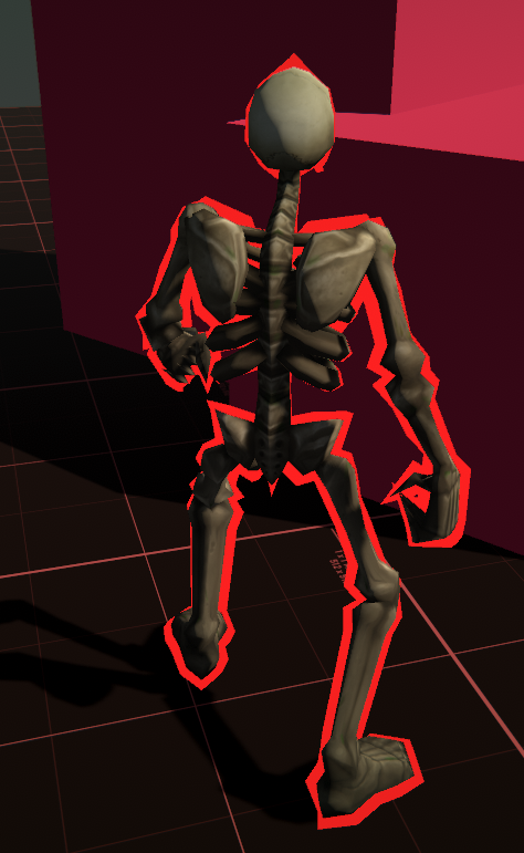
Hey I am looking for help solving a fairly common problem regarding outline shaders
There's extremely large gaps between the creases of the outline
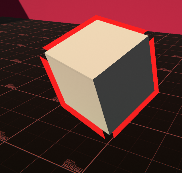
Now I already know why this happens, it's because of the normals of the mesh
and it can be solved by smoothing normals, softening edges, etc. etc.
but this will still be problematic for me because I definitely want to go for that hard-edge look for my assets
Is there a performance-friendly / smart solution to stop this from happening?
I've heard some guides saying to store a copy of the mesh that's smoothed for the outline but that seems like it wouldn't be the most optimal approach
@grand jolt You can have the same mesh, you just need to store an extra normal direction in each vertex. The original hard normal and a smooth normal.
I'd argue that is the optimal approach
Is that done in the 3D application or is that done in the shader?
In script would be the easiest
I'm thinking I want to go with a hard-edged aesthetic, wouldn't that mean every object that wants an outline would need this script?
and if so, is that okay?
This would be a one time calculation for each mesh, and it could even be done in edit mode and saved and loaded in builds.
https://github.com/chrisnolet/QuickOutline uses this approach

GitHub
Unity asset for adding outlines to game objects. Contribute to chrisnolet/QuickOutline development by creating an account on GitHub.
But it's a little outdated and does things less optimally
I'm also using Amplify to create my shaders, not sure if that matters
It copies the original mesh, modifies it and replaces it at runtime.
But you can add additional data to MeshRenderers with this property:
https://docs.unity3d.com/ScriptReference/MeshRenderer-additionalVertexStreams.html
ohhh
Then you just need to create a Mesh containing just the smooth normals, maybe stored in the second or third UV channel
Then you will be able to access it as UV1/UV2 in the shader
Okay I'm a little confused, because you are probably speaking from a GLSL perspective right?
No. I call it UV1 because that's what it's most commonly called in node based shader tools, like Amplify and Shader Graph.
TEXCOORD1 and TEXCOORD2 if you prefer HLSL
Here's a Quick Outline calculates the smooth normals
https://github.com/chrisnolet/QuickOutline/blob/270ec3d26327c466318d519aa150319d9a70e3f5/QuickOutline/Scripts/Outline.cs#L206
Couldnt I also just go in my 3D application, smooth the normals of the mesh, and use the data from that?
I don't know how easy it is to store that data in a different vertex attribute than the normal
While also saving the actual hard normals you want
I doubt any 3D application has export options for that, probably requires scripting, like Python in Blender.
I understand what you are saying but I am extremely confused as to how I'd do this in Amplify >,< here one second.
My outline shader is extremely simple right now
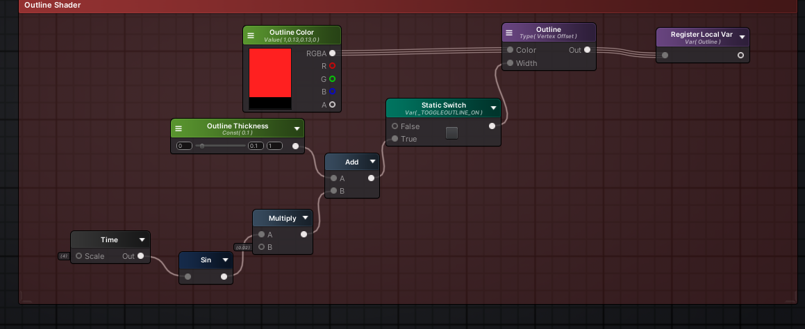
I hook this up to vertex offset
What does the purple Outline node do?
Its a built-in amplify node that does exactly what it says, creates an outline vertex offset
here
These are some of the properties
You will have to recreate what it does because it's going to be reading the vertex normal to do its calculation
wait, ive been using this outline shader, unfortunately i couldnt get it to work with urp yet,
https://github.com/michaelcurtiss/UnityOutlineFX

GitHub
Implementation of Unity's Editor outline for runtime. Shader code taken from: https://forum.unity.com/threads/selection-outline.429292/#post-2776318 - michaelcurtiss/UnityOutlineFX
I'm using LWRP right now 😛
You can make an AssetImporter script that will automatically calculate smooth normals and store them in a UV channel to be used in shader. There was a script floating around that did this but I can't find it right now
You'd store the smooth normals as a texture? O.o
UV channel isn't a texture
That's a post processing effect though. Not as clean as the inverted hull technique.
I know but
UV is just a Vector4 that is stored with each vertex
UV channels are just float4 vertex buffers
(URP) Using a metallic surface, how can I have uniform metallic highlight direction regardless of object position on screen?
Sorry my mind just defaulted to UV unwrapping
oh, is inverted hull a material added to the object?
If you really wanted to, you could also store it in the vertex color attribute
Yes, it's drawing the mesh twice, once normally and once a little larger than the original with the color of your outline.
hmm, that seems quiet more performant tho -- drawing the mesh twice,
or am i wrong in asuming that?
I'm not sure how else you'd do the outline
Do you mean heavier?
Yea that's what he means
yes -- srry .-.
Post processing is very heavy on mobile, so it's certainly going to be more performant to draw some meshes twice there
If you're already doing post processing, the post processing method might end up being more performant
With the post processing method it's still the same, you're rendering the mesh again in an offscreen render texture
my current implamentation was as simple as adding an object renderer to an list using this:
where in update it will check with a temp list to see if its different, call a function to update the list
So I am going to have to recreate the Outline shader logic manually in Amplify no matter what right?
If I want to do this
Yes, but it's super simple.
Vertex Position += Smooth Normal * Outline Width
Wouldn't say it's the same. It's handling rendering a full RT then instead of simply rendering some fragments again to the existing graphics buffer. Also the math when doing it post-process is a fair bit more intensive if you want anything more than a 1 pixel outline
Yeah on paper ;_;
Well yeah, not the same, just saying both methods are rendering objects multiple times. The post-process will definitely be more expensive with thicker outlines, and even blurring.
I'm seeing 5 nodes there, 3 for getting those 3 values, an Add node and a Multiply node.
Is your Amplify shader a separate shader specifically for the outline that you add as a second material?
I feel a little lost, I know how to do all the vertex offset logic, but I don't understand how to get the smoothed normal data into amplify
nope
I'm putting everything under a mega shader
Are you defining multiple passes?
I don't even know how to do that in Amplify
I spent last week trying to figure it out and couldnt
Getting it in amplify would probably be a Texture Coordinates node, changing the UV set on it. Or pass it through vertex colours.
But yeah, I think the Outline node thing is creating a separate pass. Multi-pass shaders don't exactly play nice with LWRP/URP though, It'll break the SRP Batcher.
Okay, so just the presence of the built-in Outline node is creating a new pass
Ohhhh
It would be better to do it in a separate shader, and use the RenderObjects feature on the Forward Renderer to re-render the objects you need outlined with the outline material.
I thought multi pass shaders just didn't work in URP period. I thought it only ever drew the first valid pass it found?
I don't know, I am still a scrub with shaders so this is very foreign to me
Is a pass just it's own self-contained thing?
It'll only render the first one with the UniversalForward lightmode tag, but it'll still render passes without a lightmode tag if I recall correctly.
You can think of it as defining multiple shaders inside one Unity shader
Okay that makes sense to me
But yeah, I think using RenderObjects and a custom shader for just the outline is the best route.
That way you can apply it to any object with any shader, so long as they also have smooth normals
You can still make that outline shader in Amplify. Just as an Unlit shader.
And is it easy enough to toggle on and off the outline for individual entities?
It's as easy as switching the Layer the gameobject is on
There's even a separate layer value you can change on the renderer so you don't need to change the game object layer
Wait that's not how you do it is it?
I'm using layers right now for masking stuff
I've never used render objects before so it's also completely new to me >,<
Well, there's also RenderingLayerMasks on the renderer as Mentally mentioned.
But... the feature doesn't actually support them by default
Really? I swear I've used it with RenderObjects before
I guess it might have been a custom renderer feature
Yeah, it doesn't have an option to filter based on renderingmask. No idea why it wasn't included
Cool thing about the rendering layer mask is that it's a mask, so you can have multiple layers selected on one renderer.
And assign different effects on each layer
It's a fairly simple edit though to support it

Download the project template here: https://bit.ly/outline-effect
Unity's tutorial: https://www.youtube.com/watch?v=joG_tmXUX4M
Brackeys tutorial: https://www.youtube.com/watch?v=szsWx9IQVDI
····················································································
Checkout my Low Poly Floating Islands package:
https://bit.ly/lwrp-f...
Is this kind of what you are talking about?
They're using a sobel post processing one rather than RenderObjects
Ahh.. hmm
If you want to try to implement this, I'll be here if you need help. And I'm sure Cyan will be able to answer any question I don't know the answer to.
Sorry I am just a bit overwhelmed lol, I've had like 100 new things thrown at me
Specifically it's the one from the UniversalRenderingExamples : https://github.com/Unity-Technologies/UniversalRenderingExamples/tree/master/Assets/_CompletedDemos/ToonOutlinePostprocessCompleted
I think that project also has a RenderObjects + hull outline example too.
I first need to even understand what Render Objects are and where to even find them
I'll need a bit
LWRP and SRP are the same thing right?
SRP is Scriptable Render Pipeline, which consists of both HDRP, URP and Custom written ones.
LWRP is the same thing as URP, it was renamed
Is there any easy way to tell what type my project is?
Because I am not even sure now
SRP is just an overarching term for all scriptable render pipelines. You can't be using just SRP.
You can check which render pipeline is set under the Project Settings -> Graphics

Then you're using Unity's Built In Render Pipeline
Ah, does that support Render Objects?
Which doesn't have Renderer Features or Render Objects
welp
The only option in built-in is either multi pass shaders or multiple materials on each renderer
I've heard lots of things having issues with URP/HDRP so when I created this project I avoided it
I have a highlighting system in the built-in render pipeline which adds the highlight material as a second material on renderers that need to be highlighted
Having multiple materials on renderers with one mesh will draw the renderer twice with each material, same as a multi pass shader.
So what you are saying is that, with an outline shader, you will basically always have to render the mesh twice
is that correct?
Yes, at least the approach you want to do
What would the other approach be?
That works for built-in
something camera related?
Most approaches require drawing the mesh multiple times in some fashion
It's theoretically possible to implement a post processing outline shader that maybe uses the alpha channel to identify what pixels to draw an outline around
Or use edge detection
That doesn't require drawing the mesh multiple times
Some games have fuzzy/soft outlines
But this is both more difficult to implement and worse performance than just putting two materials on renderers
I thought that's what they did
What kind of outline do you want?
I think solid
I think it would look the best
Soft is nice, but I dont think it'd fit
Do you want an outline only around the outside of the mesh or also on the inside where edges are?
Only on the outside
Then it sounds like inverted hull outlines like we've been discussing is the best approach for the type of outline you want
haha
So I guess I should push it into a 2nd material and remove it from the original shader
Oh shit
I totally forgot
aaaaa
I am already using a 2nd material
one for XRay
It stacks, Unity will draw the renderer as many times as there are materials
Isn't drawing 3 times kinda bad though? ._.
wait
I guess aren't I already doing that anyways
That's what your current outline is doing already
What platform are you targetting?
PC
I wouldn't worry about it then
Do you think you will only need this outline on renderers that are using your custom Amplify shader?
Or would you like to be able to use it alongside any shader?
Yes
wait
hmm
My idea was to have a mega shader that I can toggle effects on and off
and I would ideally have anything that may use those effects under that shader
the environment might be another shader, but it would still be amplify
I think all of my shaders will be with Amplify
Amplify has support for defining multiple passes in one shader, as far as I know
Something Shader Graph doesn't support
It does but honestly I cannot find anything on how to do it, the documentation seems nonexistant
Use Pass is not what you want
It's a way to reference another pass defined in another shader.
Though I guess you could create a separate outline Amplify shader and then Use the pass from there
See I did see that doc before
But I have no clue how they even set that up
There's two output modules
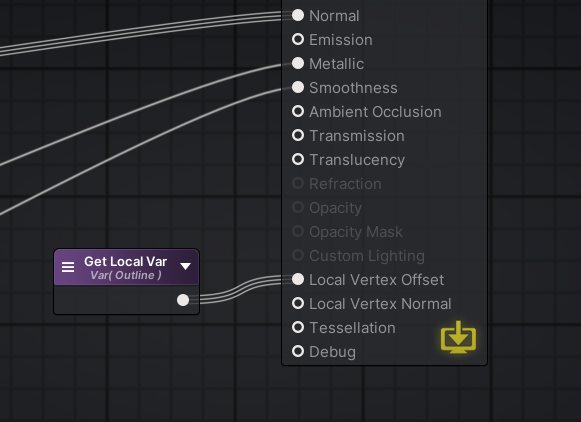
And if I create that node this is all I see
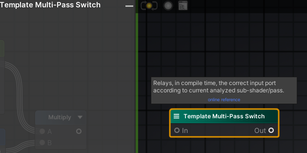
Yeah, I don't know if you need that to define multi pass shaders
shrug
but I dont need to do this right
I can just have my outline shader be its own thing
then i add that as a material to the mesh
in this case it'd be my 3rd material
Sure, but it's easier to toggle a pass in a material than it is to add new materials to a renderer
Renderer.materials is an array, so you have to create a new array each time to add a new material
But on the other hand, a separate material allows you to apply it to any renderer, regardless of what shader their main material is using.
The latter sounds very appealing
There is another option
I forgot this is what I did for my highlighting system
Command buffers
CommandBuffer is a list of graphic commands you can execute with Graphics.ExecuteCommandBuffer, but you can also add command buffers to cameras and tell it to execute the commands at a certain point during rendering
So you can do:
CommandBuffer buffer = new CommandBuffer();
buffer.DrawRenderer(renderer, outlineMaterial);
camera.AddCommandBuffer(CameraEvent.AfterOpaque, buffer);
And then it will draw renderer with the outlineMaterial after it has drawn all the opaque renderers.
I think the code ends up looking less complicated, simply because of how much of a mess it is to add new materials through code.
The way I thought it'd be is just another material on the renderer, and in code I just access that material and toggle a public property on it to turn the outline on/off
For best perfomance, you would want to remove the material off the renderer when it's not being used
Because the extra draw call will be just as costly on the CPU no matter what you do in the shader.
Ohh
Would removing and re-adding a material not cost a lot?
I just assumed it would
Most things related to rendering is done fresh each frame. So it doesn't really "notice" when suddenly it's not being asked to draw a renderer with a material anymore.
The cost is probably mostly in just creating the new array each time
Because of how terrible Unity's ancient material scripting API is
Which is why I avoid it by using command buffers
Command buffers are kinda similar to Render Objects in URP
Or Render Features in URP in general
In that they allow you to execute graphics commands at certain points during the rendering pipeline
Sorry I am just setting the shader up in amplify rq
Okay it's all set up
So that vertex normal node needs be the actual smoothed vertex normal data
and then it would work right?
Does it looks like an outline with just this?
It should, just with the broken edges on hard meshes
Then yeah, you just need to replace the Vertex Normal with the smooth normal
You can't do this in the shader because you can't access data from other vertices
And even if you could, you wouldn't be able to know what vertices are connected to what vertices. They only thing they share is their position. They're not connected in anyway.
Quick Outline calculated the smooth normal by grouping together all the vertices that are in the exact same position and averaging their normal values.
He uses LINQ for that. Probably not the most optimized way to do it, but certainly the simplest
https://github.com/chrisnolet/QuickOutline/blob/270ec3d26327c466318d519aa150319d9a70e3f5/QuickOutline/Scripts/Outline.cs#L206
You mentioned something about only having to do this once, how is that possible? Don't a need a persistent reference to that smoothed normal data?
You calculate the data once
Then you keep it stored in the mesh
And the shader gets access to all the data per-vertex
I haven't checked the link just yet but, (and sorry if you are repeating) how do you store that data in the mesh? Is that what you were talking about earlier by using another UV channel?
Just trying to fully wrap my head around this
It'll click soon
the smoothed normal data just has to be accessed in amplify, and i substitute my "Vertex Normal" node with that data
the block on your script you linked returns a list of smoothed vector3 data, smoothed normals
Yes, you would then want to put that data into the mesh in one of the attributes, like one of the UV channels or even as the vertex color.
You could do that the same way Quick Outline does, by duplicating the original mesh and modifying that mesh to add the additional smoothed normals into one of the vertex attributes
Or you can use the additionalVertexStreams property I linked earlier
I would recommend that approach, because it doesn't require duplicating the whole original mesh
It keeps using the same mesh, you just give the renderer a second mesh and tell it "Merge the data from this mesh into your mesh before you hand it to the GPU"
That's what additionalVertexStreams does
And I think I asked this earlier, but is there any clever way of doing this in my 3D application to have a cleaner workflow?
Like somehow baking this data
What 3D application are you using?
Like I said before, I really really doubt there's any setting in Maya or any 3D modelling software to be able to export special data into meshes like this
Short of scripting it, like in Blender with Python
Hmm ok
You could possibly export the mesh twice, once with hard normals, and once with smooth normals, maybe somehow telling Maya to put the normals into one of the UV channels
And then set additionalVertexStreams to the second smooth normals mesh
But this doesn't sound like a cleaner workflow
Compared to just adding a script to a game object
Just for clarification, doesnt that script have to be attached to every object that I want this to happen to?
just take the code you posted earlier, but apply it in OnPostprocessModel using an AssetPostprocessor script. You can then have the smoothed normals automatically added to the asset itself whenever imported
I dont understand how it would only work once
If you do it in a script, yes you would have to add this script to every object you want to add an outline to. Unless you have one script that finds all renderers and does this modification to them.
But then it's more difficult to control which objects get this modification, same with an asset post processor
Can just filter out by directory name or some other organizational option
Woah jesus, unless I am misunderstanding - does that just make it so any asset I import have the solution automatically applied?
yes
what the
and you can do whatever else you want to the asset, like add scripts even
w o a h
wait
wtf
i didnt know you could do that
I dont attach this script to any object, it just runs whenever I import right?
yes, just put it in an Editor folder
But I would definitely find some way to filter which meshes you modify. Doing this calculation for all meshes, especially big meshes, will slow down your import time and increase your build size.
You can introduce breaking references changes in some cases if you rely on adding scripts this way is the main downside, better to rely on the prefab system for added components so that what you add is separate from what you import and doesn't get affected by the import process
I don't know if you can somehow add a checkbox like the built-in model import settings
That would be the best solution
assetPath gives you the directory the mesh is in, so you can filter that way if you want
nah you can't add a checkbox
I personally relied on the Label system, but that requires some extra code to grab that info
This feels like witch craft
or for adding colliders i'd just add like __COL to object names in the asset
yup that works too. Could even include an empty game object called "ADD OUTLINE" and delete it on import
and if it reads that somethingsomething it will run the code
And just for clarification
say I import a model into Unity
and it runs this script
if I close unity
and reopen it
yes the change is saved to disk
Unity only imports assets if they haven't been imported already. It gets saved into the Library folder in your project. Restarting Unity doesn't affect it.
And if you force a reimport (which you can do in the right click menu of the asset), it will run your import script again.
Okay so how does AssetPostprocess differentiate between objs, fbx, or even stuff like pngs and audio files?
Does it only detect meshes?
oh wait
If you make a PostProcessor, it will run your script after it's converted the raw file type into the Unity equivalent
nevermind
I see now
So is OnPostprocessModel only acting on the mesh itself
so if I had an fbx that for some reason included other non mesh components, it wouldnt act upon those
no, it works on Model imports
On the model asset, which may include multiple meshes, materials, cameras, all kinds of things
there's post processors for various major asset types
wow
Okay damn
Then there's ScriptedImporter for writing importers for types Unity doesn't already recognize
So the documentation is using GameObject as a paremeter
I can just change that to Mesh right?
You can even write your own importer for a format unity doesn't recognize: https://docs.unity3d.com/ScriptReference/Experimental.AssetImporters.ScriptedImporter.html
Like if you wanted to make some .myData file that contained some text structure of data or w/e
No, models get imported as prefabs. The mesh will be stored as a sub asset and referenced in the MeshFilter component
Just imagine it as if you dragged the model into the scene and wanted to do stuff to it with scripts
Oh shit I see now
That's sick af
So now from this method I need to grab the mesh component, pass it into the SmoothNormals method from that linked script
and then I need to figure out how to store that received data into the mesh
sounds about right?
Yeah
alright one seccc
What's the proper way to pass in the mesh component of the GameObject parameter?
its not getcomponent is it?
I think that's the only way
You'll probably have to use GetComponentsInChildren<MeshFilter> to grab all the meshes in the model.
oh
hmm
Wouldnt that by an array of meshes
So if I have multiple meshes, ill have to run SmoothNormals on each one
and SmoothNormals returns a vec3 list
so ill need a list of lists
right?
foreach (MeshFilter meshFilter in model.GetComponentsInChildren<MeshFilter>())
{
    List<Vector3> smoothNormals = SmoothNormals(meshFilter.sharedMesh);
    sharedMesh.SetUV(2, smoothNormals);
}
I use channel 2 here because channel 0 is normally used for main texture and channel 1 is often used for lightmaps.
I misstyped, it's SetUVs
Right
ok
im going to import a cube for testing
So now that that's done, I need to reference this data in Amplify
one sec
Amplify UVs start at 1, so to reference channel 2, you need UV number 3
And then change Coord Size to Float3
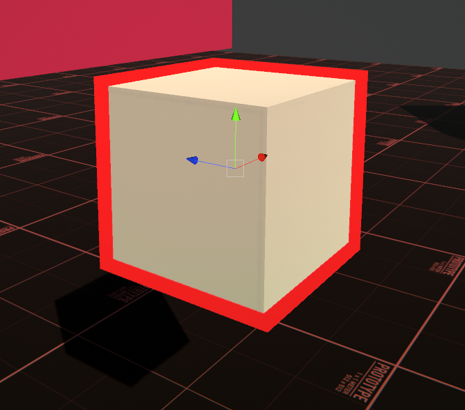
I'll be honest, I wasn't expecting it to work the first time without some troubleshooting
Lemme test with something more intricate
holy shit
you're a god, I could cry
well and @still carbon
Points to @still carbon for mentioning asset postprocessors. Totally forgot those existed.
I should do that tag filtering thing
Oh is there a way to force a model to reimport
or run that script on it?
Yes, right click and re import
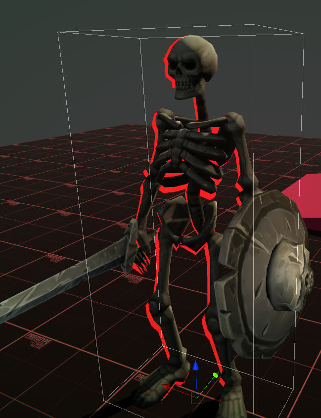
Damn my test skeleton is from the asset store so i think I actually have to redownload that
cause reimport doesnt seem to work
I don't see why that wouldn't work
yeah i dunno
this is def not right
easy way I can test if its running is just doing a debug log in the script
It might be something to do with skinned mesh renderers
I don't know if something special needs to be done to support those
Wouldnt that mean the outline would be static though and not move with the mesh as it animates?
cause the outline is moving
its just off
Oh lord
lmao
I tried switching it for skinned mesh renderer and this happened
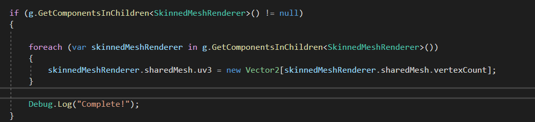
This is what Quick Outline does:
// Clear UV3 on skinned mesh renderers
foreach (var skinnedMeshRenderer in GetComponentsInChildren<SkinnedMeshRenderer>())
{
    skinnedMeshRenderer.sharedMesh.uv4 = new Vector2[skinnedMeshRenderer.sharedMesh.vertexCount];
}
My guess is its-
I'm not sure what that accomplishes
It does that after looping through the MeshFilters
just use GetComponent rather?
if I import something without a skinned mesh renderer i do get errors
You get a null reference exception without that if statement?
mhm
Nothing changed
Are you reimporting each time?
You didn't have a debug log in your last screenshot
I wrote it immediately after
if i do GetComponentsInChildren it will actually run that block
just for now ill keep it there
so its printing now
Still makes no sense to me that GetComponentsInChildren is giving you null
I dunno
I think I explained that horribly
If i write this
the entire block doesnt happen
it wont print
if I do this
it will print
because it actually executes
Well yeah, because you're trying to find a SkinnedMeshRenderer component on the root model game object
sorry, i suck at explaining stuff ><
yeah
GetComponentsInChildren searches the given game object and all of its children
and if I dont have that if statement at all, i will get errors
so because this isnt a MeshFilter
that first block isnt running at all
Try this:
var skinnedMeshRenderers = g.GetComponentsInChildren<SkinnedMeshRenderer>();
if (skinnedMeshRenderers == null)
{
    Debug.Log("Wow, I got null somehow!");
}
thats probably the first problem
I didnt print when i reimported the skele or the cube
The null is probably happening somewhere else
Maybe one of the skinned mesh renderers has its sharedMesh set to null for some reason
o.o
I'm almost certain that it isn't because GetComponentsInChildren is returning null
It doesn't do that. It gives you an empty array if it found nothing
oh
hmm
is it worth worrying about if the null check conditional prevents it from throwing errors?
If it's erroring, it's probably a clue we're doing something wrong
And adding a null check just hides it
hmm
does MaterialPropertyBlock work on URP materials too?
is it the right tool if i want to achieve dynamic recoloring for objects?
Yes, but it prevents the SRP Batcher from batching your renderer properly
SRP Batcher prefers you using material instances
It will look fine, it just won't be as performant
so i should rather define a new material for each color you say
oh I dont know if I mentioned this
This makes no outline show up
You can also just not have the SRP Batcher enabled and just use the built in batching which supports property blocks properly
@grand jolt That's what I would expect that line to do, so I don't know why Quick Outline does it
is that less performant than SPR batcher?
quick outline is an asset store item isnt it?
oh yeah i have it downloaded LOL
@grand jolt In some cases, yes. In other cases, it's more performant. But in general, SRP Batcher is supposed to be better in all cases.
@grand jolt I think in most cases, the difference is minimal
i see
It's only if you have a crazy scene that's using all the same shader with slightly different material settings that SRP Batcher handles better
@grand jolt I think all that QuickOutline is doing is just not assigning any smooth normals to skinned mesh renderers
Oh?
It's doing this in its shader:
float3 normal = any(input.smoothNormal) ? input.smoothNormal : input.normal;
So it's checking if the mesh has any smoothNormal values and if it doesn't it just uses the regular normals
That's why it's just clearing the normal values for skinned mesh renderers
Hmm
The reason is because the mesh skinner processes not only moves vertices to follow bones, it also rotates the normals
But it isn't aware of the smooth normals, so those stay unchanged
And pointing in the wrong direction
So unless I am mistaken
You could possibly change the smooth normals to be relative to the regular normals
what I am doing is correct, but its within the outline shader that's actually checking?
his outline shader
It's not exactly "correct". He's just ignoring skinned mesh renderers and letting them have broken regular normals
Which is fine when you have a smooth mesh, which most skinned meshes are
And probably why no one has mentioned that it's broken
what if they aren't?
Then you need to find a smarter fix than what he did
What if the skinned mesh has hard edges ins-
oh ok
wait what you are saying entirely explains the deformation of the outline
hold on
I would expect the outline to be correct if all the bones are in the default position
Because that's when the smooth normals are correctly rotated
But as soon as bones start rotating and moving, the regular normals get updated to reflect their new rotation, but the smooth normals get ignored and stay the same

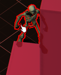
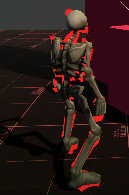
the outline shader pulses
but this is kind of what you are talking about right
its a gif
it might need a bit to load
Not loading
https://i.imgur.com/Uz4Unvu.mp4
Also I never thought that fixing an outline shader would be this difficult lol :p
well
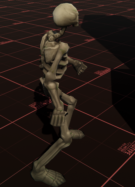
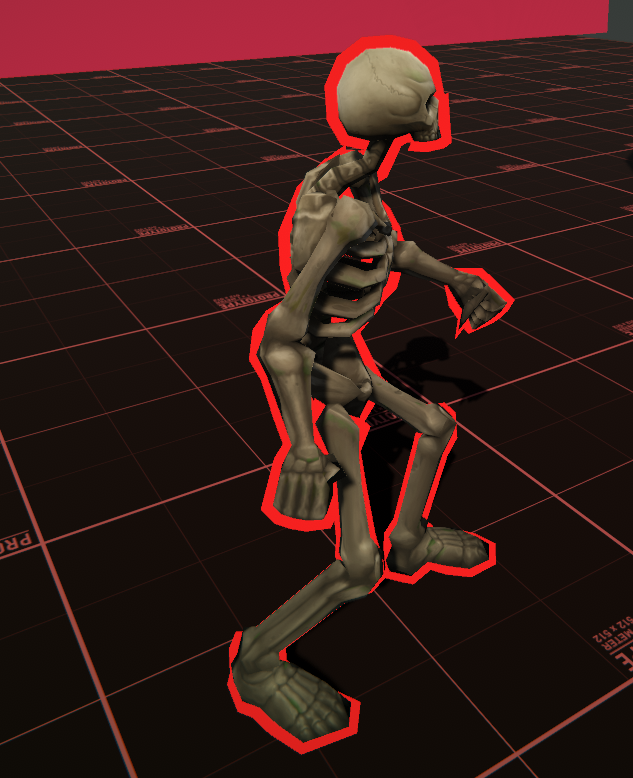
to describe it, the outline looks like its squeezing into itself
That skeleton doesn't look like it has hard edges though
Are you going to replace it?
There, it loaded now
and thank god too
You might be able to store the smooth normals as the tangent
The mesh skinning processes should rotate the tangent along with the normal by the same amount
I'm not sure if I know what you are referring to when you say tangent
Usually, the tangent is supposed to be 90° from the normal and sometimes used in shaders to calculate specular effects with normals
ah -- no success,
how long would it take for someone with near 0 shader exp to be able to convert some cg shader to hlsl?
@glossy matrix CG and HLSL are nearly completely identical
They are the same language, it's just CG came first and HLSL derived from it and took over
ye -- came across the history -- nvidia released cg first with microsoft following with hlsl
syntax are similar, but more often than not i saw people calling them complete different languages. .
in a normal compilation setting they are, but unity just treats CG as HLSL now and handles any edge cases
@grand jolt It's worth a try, at least just see if it breaks with the regular meshes. Try replacing SetUVs with SetTangents. It's expecting List<Vector4>, so just modify the SmoothNormals method to return that instead.
i see, thats why the shader compiles and not go into a frenzy -- even tho the output may not be whats desired
@grand jolt Then use the Vertex Tangent node in Amplify instead of Texture Coordinates
sure let's try it
wait
before I do this
this will break non skinned mesh objects right?
if has skinnedmeshrenderer else has mesh filter
@grand jolt The hope is that it doesn't break anything
That's what the test is for
ok lets test
one sec
so
it definitely changed
but still scuffed
at certain angles it looks decent
in amplify?
Yes
no change
this is what I did
Since I no longer have that tex coords node hooked up its just fucked on the other models
but that makes sense
This should work on normal models too
I would expect them to look just as they did
We're just storing the smooth normal in a different place
I didnt reimport the old models
Try it
I also didnt replace the code for SmoothNormals
i just made a SmoothTangents
I can try it with them if you want
Well, even though this might work (though it doesn't look like it works perfectly since its still a little scuffed), storing the smooth normal in the tangent is not optimal
Because unlike the third UV channel, the tangent is often in use
It's necessary for normal mapping
So this would break that
Hmm, that's unexpected
oh wait
no
thats my fault
i didnt update the shader
yeah it works
i forgot to switch back to the vertex tangent node
normal maps will almost certainly be used in the future
Trying to think of other ways to rotate the smooth normals along with the regular normals
If we could hook into Unity's mesh skinning, it would be pretty simple to just do the same operation to the smooth normals
But I don't think that's an option
mhm
Unless...
I can think of a dumb ghetto fix for this but its not optimal
and especially not friendly in terms of workflow
I was thinking maybe it was possible to replace the skinning compute shader with our own modified version, since the skinning shader is available here:
https://github.com/TwoTailsGames/Unity-Built-in-Shaders/blob/master/DefaultResources/Internal-Skinning.compute
But it doesn't look like it can be overridden.
There are some built in shaders you can override in the Graphics settings, but skinning isn't one of them
hmm
You can see in that shader that it's modifying the position, normal and tangent
That's why it kinda worked to put it in tangent, since it was then getting modified
Not exactly sure why it was still a bit weird though
I know it's possible
Gunfire Reborn has that hard-edged aesthetic and an outline shader as well
and if I remember correctly, it doesnt have this problem
With skinned meshes?
Is that a Unity game?
mhm
I don't know, kinda looks like post processing outlines to me
Hmm, no actually there are some thicker outlines later in the trailer
wait lemme watch a vid

Walkthrough Guide For Gunfire Reborn . It is a 4 player coop roguelite first person shooter and is available on PC through Steam.
This video is a guide for the game
Walkthrough [Full Game] Playlist: https://www.youtube.com/watch?v=nUz0qUdtvCI&list=PLAUKgYvlj3Pwfn_d8uA4TriXOx3m4kyM6
Boss Fight Guide for Gunfire Reborn: https://www.youtube.com/w...
when he hovers over enemies
yeap
Part of me wonders if the solution is actually really easy and we're just overcomplicating it
I'm pretty sure Gunfire reborn started as a student project
i saw a video just earlier on it, here ill link it (using shader graph)

This is a smooth outline shader,
Thanks to GlassToeStudios!
►-------------------------------------------------------◄
Join the community, keep on learning.
► Come hang out in discord! This is the most efficient way to reach not only the team members but thousands of other developers like you! We love it when you help, showcase or just discuss ...
wait no ;-; nvm -- thats old
fk -- maybe it was another one
I don't think so. Skinned mesh renderers complicates things
You could export the skinned mesh renderer twice, once with flat normals and once with smooth normals
that's the ghetto solution i was thinking of
I think I have one more idea though
Slightly more complicated to implement, especially in Amplify
Might require a custom expression/code function
That's doable
The idea is to calculate the rotational difference between the flat normal and the smooth normal for each vertex
As a Quaternion
This wouldn't be done per frame would it?!
Then in the shader take the flat vertex normal and apply the quaternion in the opposite direction to get back the smooth normal
Yes
To calculate the Quaternion in script, you could do:
var rotationDifference = Quaternion.FromToRotation(normal, smoothNormal);
Or the other way around
We want the rotation from the regular normal to the smooth normal, so we can apply it in that direction later.
can somone help me with shader graph?
the shader graph ui is ery small for some reason
@grand jolt Let's move to DM maybe?
Yes
https://www.youtube.com/watch?v=1QPA3s0S3Oo
found it -- it wasnt shader graph tho ;-;

✔️ Works in 2020.1 ➕ 2020.2 🩹 Fixes:
► If importing a model, be sure to enable read/write access in the asset inspector, so the normal calculator script can read it's data correctly.
Outlines are a fun technique to add style to your game and pair perfectly with toon shaders. There are a variety of ways to implement them, and in this video, I lo...
enyone?
should be able to just scroll mouse wheel to zoom in?
thats looking pretty good!
thanks
But yeah, this will fix outlines on anything that's hard-edged regardless of it being skinned or non-skinned
metally guided me through it
aah -- guess im stuck on this. . kinda getting late, should head out
just gonna throw this out there - kinda far fetched but if anyone could help convert this to hlsl that would be much appreciated
shader: https://hatebin.com/hesjmdosjq
outline manager (uses ray cast, stick it on camera should work): https://hatebin.com/slumwuaomz
outliner cam effect (stick this script also on camera, applies the effect): https://hatebin.com/pwzmqzidii
(Original github link: https://github.com/michaelcurtiss/UnityOutlineFX -- outline manager is re-written for mouse selection - outliner has minor tweak to update objects at runtime)
- current issue: doesnt work with urp. . . (works fine in srp)
Thanks if anyone does bother, guess ima head out -- GL
GitHub
Implementation of Unity's Editor outline for runtime. Shader code taken from: https://forum.unity.com/threads/selection-outline.429292/#post-2776318 - michaelcurtiss/UnityOutlineFX
do epic maths
(probably just multiply them together)
but depends what u r looking for
u may add them
divide them, replus them, make one power of the other
use your creativity
experiment
I tried all of the suggested, and it does not produce the same result
Which is why I am asking around
Does not preserve the bigger bubbles
Getting closer, but not yet
The first pictures you showed are two voronoi with similar size. One of them is just inverted. I guess that you should’t have different sizes if you want to create the third texture
I will try that
The 3rd picture is actually 2nd picture with 3 octaves
And there is no "Octave" parameter in shader graph's voronoi
Its from Unreal Engine guide
Not sure how to recreate that
You have to create the octaves yourself. They are created by combining several textures of several sizes
Sadly so far I am not getting close yet
Not sure what goes on behind that octave thing
hey can shaders made in unity 2020 be used in older versions of unity like 2018,20?
@astral pecan I am trying to recreate it now
Alright, thanks a lot @viral knoll
Sorry for the trouble
1st pic is Voronoi with Power 2
2nd pic is inversion
3rd pic is Octave 3
Anyways playing around got me to accidentally make clouds out of a bunch of tumors
🤣
This is what i got with octaves
If that's inverted, it might work..?
Sure thing, send me when you're not busy, thanks a lot for the help!
How octaves are usually done :
- Noise value is in -1;1 range
- for each octave, you multiply the UV (or position input) of the previous one by a constant.
- and multiply the influence by an other constant.
- sum the octave*influence to the result
I think that the voronoi of SG is in the 0;1 range, so in your case :
- remap both noises from 0;1 to -1;1
- multiply the smaller one by a constant (let say 0.5) to diminish the influence
- add it to the big one
- remap the result form -1.5;1.5 (sum of the max and mins) to 0;1
Hi I try to do wave shader on my sprite (2D) and other parts of the uv is showen. dose anyone know how to ignore this part?
You could clamp it, but then you'd need to know what the min and max UV values for this sprite are
Which could be anything when it's part of an atlas
I don't know if Unity passes that information to the shader
I will try to find a way thanks!
After some short googling, it looks like you have to pass that information to the shader manually through a material property
I thoght so.. Thank you!
Hi, i've got this setup:
The presentor is on a layer: 'Videoplane'
The ground and the carpet are on a layer 'Behind videoplane'
What I want to achieve is that The videoplane always renders over the behind videoplane layer and all other depth should be preserved.
can anyone tell me how I should set up the custom passes in such a way
I guess it's all in the depth override settings, but I don't really get what happens when I turn on 'write depth' and what 'Equals/Less Equals/Greater/etc.' values do exactly
so an explanation of those values probably gets me going as well 🙂
Thanks, I will give it a try!
I'm trying to have a smooth gradient on a sphere. Sort of like fresnel, but smoother I suppose. I want to use it for opacity, so the outside has an opacity of 0 and the inside of 0.85, and smooth that out between them.
It's probably a dumb question. I tried doing fresnel with one-minus, but it's not smooth enough. I want to make floating glowing orbs coming out of a surface.
IF you can use just alpha cutout, i.e. set shader to opaque and use alpha cutout this maintains z depth. While transparent queue does not, it may solve the problem for you
how would that work with any objects in front of the plane?
they would appear infront
and the feet in the image (that are now cut of because of the ground and carpet would also be in front of those?
depending on your shader you maybe able to test it by just swappig the render queue to lower than 3000, are you using a built in shader or custom?
I have a normal HDRP/Lit shader on it now
it's not going to solve the feet problem, you would have to move the plane upwards as a simpler solution. But it would allow for objects behind and in-front to render correctly based on depth.
as it's not a 3D object you are going to have awkward angles where it will look wrong, unless you restrict where / how it's viewed there will be no getting around that aspect. depending on your project aims, if it's for client control / a composite video render etc.
How do i convert HSV to RGB in compute shaders?
Google this part of your question:
HSV to RGB in compute shaders
all other clipping isn't really a problem, its really the feet problem that I'm trying to solve, the guy you see on the plane will be replaced with a live greenscreen feed that is chroma keyed. if that person however would move towards the camera, you get the feet problem, thats why I was trying to solve this with custom passes, from all that I've read it is the way to go but I don't know enough about rendering passes to correctly use them
thanks for the help so far 🙂
shader180hsv color, BUT do you have a emission solution (lightning) ?
How would one make a digital screen that looks like this with the squares?
postprocessing
Which effect? @shadow locust
Or just overlay a texture over top?
That might be an easier way.
Anyone knows if I can have one shader with different values on different materials?
yes - that's what materials are: A shader + property values for the shader.
Okay, I guess than I am instancing the materials wrong, let me put it that way. Can I generate materials on the fly with a copy of a source material and alter them?
yes
If you use GetComponent<Renderer>().material to edit property values, it'll automatically create a material instance and assign it
So this is what I have ```
foreach (Transform tr in nodes)
{
LineRenderer lineRenderer = tr.gameObject.GetComponent<LineRenderer>();
            if (!lineRenderer)
            {
                Material newLineMat = new Material(lineMaterial);
                lineRenderer = tr.gameObject.AddComponent<LineRenderer>();
                lineRenderer.sharedMaterial = newLineMat;
                lineRenderer.sharedMaterial.SetFloat("_Offset", Random.Range(0,5));
                lineRenderer.startWidth = startWidth;
                lineRenderer.endWidth = endWidth;
            }
            else
            {
                linePositions[0] = nodes.IndexOf(tr) > 0 ? nodes[nodes.IndexOf(tr) - 1].transform.position : nodes.Last().transform.position;
                linePositions[1] = (tr.transform.position + linePositions[0]) / 2 + new Vector3(0, 1.5f + nodes.IndexOf(tr) * 0.3f, 0);
                linePositions[2] = tr.transform.position;

                lineRenderer.material.SetFloat("_Length", Vector3.Distance(linePositions[0], linePositions[2]) * 175);

                DrawQuadraticBezierCurve(lineRenderer, linePositions[0], linePositions[1], linePositions[2]);
            }
        }
But somehow, the random.range is always the same number, like if it is instancing it only once and sharing it between themto copy the material you do Material copy = Instantiate(originalMaterial);
ah actually no you're right
that constructor should work
lemme look at your code
what part isn't working exactly?
Hm, I am not sure if it was just a bad random thing, but now with instantiate, it seems to work or I just had bad luck with the numbers always being the same, let me increase the range 😄
Hm, yep, I guess it was either instantiate or just bad luck with numbers. I had like 10 times all of them being 2... Thanks and sorry for taking your time 😄
interesting ok
I guess range from 0 to 5 as int isnt that much
I'm trying to implement fog of war in URP. I'm currently using a camera that renders the line of sight to a render texture, and then use that texture to mask the output of the main camera.
After the whole day trying to figure what to do next, I want to read the depth from the camera that renders to the texture, so I can reconsctruct the world pos and use it with the 2nd camera to "work with XZ positions"
Problem is, I have no idea how to access to 1st camera depth
Any hint very much appreciated
Is it a Cinemachine camera?
It should have a public variable called FOV
It controls the length of the fustrum
Ah here we go
Camera.main.fieldOfView
not sure what cinemachine has to do there
I dont use the normal camera and only use virtual cinemachine cameras
So I cant speak to those
There is also Camera.main.depth
Depending on what you are trying to do
Haven't really done something like that. But my guess would be you'd need to blit the _CameraDepthTexture created to a custom texture ID. That might let you keep it so the second camera doesn't override it? (Assuming that's the problem here)
Thanks cyan, that looks a reasonable approach (from my humble rendering knowledge) I'll try it tomorrow 🙂
Im sure ive done this use case before 🤔
And yep, the 2nd camera overrides it
Do you need the depth texture for the second camera too? If not, disabling it might also stop it overriding it
(Should be an option to turn it off on the camera that is)
Not for any custom effect, but it is the camera that is doing all the postprocessing stuff, so I guess I'm using it, although maybe I could do all the PP stuff on an overlay camera too, i think
What I did was make a cube as a child of the camera, set its size based on Camera.CalculateFrustumCorners, and on trigger enter, enabled the mesh renderer
Ah right, yeah post processing might force it on
I controlled how much was disabled by taking a ratio of the frustrum size off
@fresh vigil I've got a BlitRenderFeature that can allow you to blit from one ID to another if you want to try it. https://github.com/Cyanilux/URP_BlitRenderFeature
Unity also has one in the UniversalRenderingExamples (linked on that page too) which they updated to work with a source & destination. Theirs might only work in v10+ though, not sure.
The two cameras should use different Forward Renderers (can assign multiple on the URP asset and set which is used per camera). Can put the blit on the first camera one, maybe in the "Before Transparents" event (or later would probably work too). source being _CameraDepthTexture, and destination being any custom ID you want.
I haven't really tested what happens with multiple cameras but hopefully it'll allow you to copy the depth over and use it while rendering the second camera. Frame Debugger window should be helpful in debugging if it doesn't work.
I already downloaded the URP examples, which I needed for the render pass, I'll look at it tomorrow, need some rest now. Thanks for the resources and hints, its gold for me 🙂
I made this shader for liquid
but there's no top face, and I can't figure out how to fix that
you can see right through the top
anyone know how I could fix this?
The technique works by faking the top face with the back faces. That's why it tends to be a solid unlit colour rather than textured.
There are ways to get it textured as if it were a top surface, but it's likely not a simple fix. See #archived-shaders message (Specifically "Assets/Shaders/CrossSection", though you'll need to download the files to view the graph properly)
hi if i make a shader using shader graph and then try adn import it to a version of unity without shader graph will my shader brake? its for a vr chat avatar
Yes your shader will break
VRChat doesn't use HDRP or URP, which is what shadergraph is able to compile for. So even though you can convert shadergraph to a shader file, it still would not work.
look up ShaderForge on github and download a recently updated branch, or buy Amplify shader editor
they work with the old pipeline
ok thx il theck it out
How to Create This Effect?
Heat wave/distortion?
Distort scene color with normals
Yes
Its the same as creating water ripple effects
Displace UV with noise, etc
A lot of ways to do it
Can I Create This With Particle System?
Yeah you probably can
How?
It's funny that you mention generating tumors with voronoi diagrams, because that's surprisingly accurate:
"Voronoi tessellations have been used to model the geometric arrangement of cells in morphogenetic or cancerous tissues, however, so far only with flat hyper-surfaces as cell-cell contact borders. In order to reproduce the experimentally observed piecewise spherical boundary shapes, we develop a consistent theoretical framework of multiplicatively weighted distance functions, defining generalized finite Voronoi neighborhoods around cell bodies of varying radius, which serve as heterogeneous generators of the resulting model tissue."
https://link.springer.com/article/10.1007/s11538-009-9498-3
:P
Don't multiply both by 0.5, only the top one.
And why the distance node ?
Higher octave > lower intensity, starting with 1 for the first octave.
Here is how I would do it
That's perfect, thanks for the guide and enlightening on how to achieve it!
Hey! In shader graph, I'm trying to use a 2D image as a mask for tweaking the vertex normals, but I'm unable to connect it. I'm unsure of the reason. What am I doing wrong here?
in vertex stage you need to use a sample texture 2D LOD node
@thick fulcrum Thanks man; saved my day!
Guys, how do i give this shader an alpha mask ? (Additive Alpha Blend Shader)
SubShader {
        Tags {
            "IgnoreProjector"="True"
            "Queue"="Transparent"
            "RenderType"="Transparent"
        }
        Pass {
            Name "FORWARD"
            Tags {
                "Queue"="Transparent"
            }
            ZWrite Off
            Cull Off
            Blend One OneMinusSrcAlpha
            CGPROGRAM
            #pragma vertex vert
            #pragma fragment frag
            #pragma fragmentoption ARB_precision_hint_fastest
            #pragma target 2.0
            #include "UnityCG.cginc"
            uniform float4 _Color;
            uniform sampler2D _MainTex;
            uniform float4 _MainTex_ST;
            uniform float _ColorMul;
            struct appdata {
                half4 vertex : POSITION;
                half2 texcoord : TEXCOORD0;
                half4 color : COLOR;
            };
            struct v2f {
                half4 pos : POSITION;
                half2 texcoord : TEXCOORD0;
                half4 color : COLOR;
            };
            v2f vert(appdata v)
            {
                v2f o;
                o.pos = UnityObjectToClipPos(v.vertex);
                v.color *= _Color;
                o.texcoord = TRANSFORM_TEX(v.texcoord, _MainTex);
                float alphaBlendFactor = 1.0f - saturate(max(max(v.color.r, v.color.g), v.color.b) * 2.0f - 1.0f); // 1 = alphablend, 0 = additive blend
                o.color.rgb = v.color.rgb * v.color.a * lerp(_ColorMul, 2.0f, alphaBlendFactor);
                o.color.a = v.color.a * alphaBlendFactor;
                return o;
            }
            fixed4 frag(v2f i) : COLOR
            {
                fixed4 color;
                fixed4 tex = tex2D(_MainTex, i.texcoord);
                color = tex * i.color;
                return color;
            }
            ENDCG
        }
    }
    FallBack "Diffuse"
}
clip(o.color - threshold);
in frag shader stage to clip per pixel.
You'll have to set the threshold variable or hard code a value there.
That is distortion cause by heat
I have a VFX graph for it, one second...
Well, I realize now this is a shader channal lol
And that is a VFX solution...
Hope it helps E:
^
Hello, I'm wondering how can I make an outline shader that works by grouping multiples skinned mesh renderers as a whole?
Nothing from the assets store works
and the only forum post that I found https://forum.unity.com/threads/add-outline-transparency-to-multiple-meshes-as-a-whole.623824/ is too old and does not work for Universal Render Pipeline
I believe its in the unity default assets 🤔
I mean is WispySmoke.png
Yeah im pretty sure its in the unity default assets