#archived-shaders
1 messages · Page 187 of 1
Is Quest/mobile VR ever going to be a target platform for you?
Alpha cutoff is quite expensive there
But so are big transparent overlapping quads, so...
very likely not. I am making it for myself because no tool besides Dreams on ps4 fit's what I want to do artistically and then see if it catches on
If Dreams is the inspiration, this asset might interest you
http://longbunnylabs.com/mudbun/

Long Bunny Labs
Welcome! MudBun is a volumetric VFX mesh tool for Unity. It procedurally generates meshes from non-destructive “brushes” that define shapes, distortion, and surface modification. MudBun can also be used for volumetric modeling and provides a convenient auto-rigging feature. Locked meshes,…
Oh interesting thanks. They would probably not like me reselling their tech as a tool though haha xD
🤷♂️ I assume the Asset Store license allows for uses like that
Haha I guess, but I'm using this as an opportunity to get a portfolio project coming out of my degree too :)
Anyways, thanks this was really helpful! :) You can follow my development here if you want https://www.instagram.com/leonardschoelch/
how do I apply an IES profile to a light in Unity?
I'd suggest learning how to UV unwrap objects rather than trying to work around it.
Blender has an auto unwrap which is pretty good at keeping scale etc correct.
However if you spend a little time and learn how to place Edges (I forget the blender terminology) to control where / how UV islands are formed you can get much better results.
There are other tools which do better auto unwrap if you really don't want to learn but the better ones will require you to get out the wallet. 😉
Only HDRP has a IES importer.
You can then assign it in the light inspector
@amber saffron Thanks for the tip! I am in URP!
You could hack it though in URP, the profiles are imported as texture to be used as light cookies.
ooo ok! I will see if I can get this working, thanks!
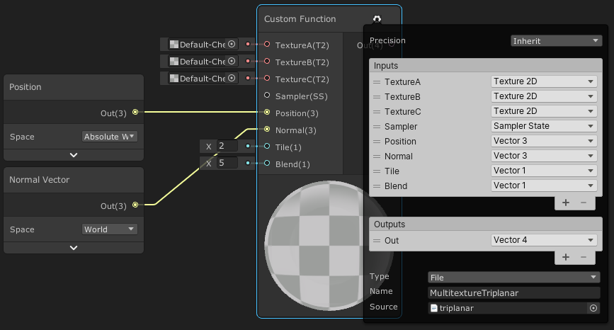
Anybody knows how to read global shader parameters either in a sub shadergraph or a custom shader node?
There's nothing more exciting than seeing this
While I haven't double checked, accessing a global shader property in a Custom Function can likely be done by either:
- Defining the global shader property in the main graph properties (non-exposed), then use it's reference in the custom function. e.g. Color property with reference
_Color. A Custom Function could output a Vector4/float4 withOut = _Color;, or use it in calculations. - Or, define the global shader property in the custom function too. This would need to be done in the file mode and would look something like :
float4 _Color;
void Example_float(out float4 Out){
   Out = _Color;
}
(I think this might cause problems if you need to access the global shader property in multiple custom functions in separate files though, as the files may be defined in the wrong order. I guess as long as they are all in the same .hlsl file it would be fine though)
- Could also just pass the global shader property from the main graph into the subgraph.
the second one looks promising. the idea was basically to wrap some global vars in a node so it is easier to access because otherwise you have to know the exact name of the global var
sadly this does not seem to work
defining a var before the function name results in a syntax error
It shouldn't do. Are you using the custom function's "File" mode? (not String)
Yep that was problem. Thx it works now
would still be great if I could somehow make it a "node" so other devs can create it from the node menu without having to select a text file etc.
You can set up a sub graph, that just has the Custom Function in and passes it out
Yeah I guess thats the way to go although its a bit redundant
I should also mention the contents of the function file should be inside something like :
#ifndef CUSTOM_DEFINE_EXAMPLE
#define CUSTOM_DEFINE_EXAMPLE
// code here
#endif
To prevent the file being defined multiple times if the graph contains more than one custom function node using it.
yeah just found that in the docs
thx for your help 🙂
i have a shader, and i decreased it's alpha value, but it doesnt make it more transparent
oh wait i figured it out
how to make shadow shader? i wanted to make fake shadow by rotating and scaling texture and tinting it black/semi-transparent.
i tried this but it doesn't work
idk how to tint texture and then "overlay" it over another one
Is it still not possible to define a custom shader pass in ShaderGraph shaders?
AFAIK it isn't, so here is a relatively painless workaround you can use:
{
    Properties
    {
    }
    SubShader
    {
        Tags { "RenderType" = "Opaque" "RenderPipeline" = "UniversalPipeline" }

        UsePass "ProPixelizer/SRP/Pixelised/UNIVERSAL FORWARD"
        UsePass "ProPixelizer/SRP/Object Outline/OUTLINEPASS"
    }

    FallBack "ProPixelizer/SRP/Pixelised"
}
You can create a new shader that then UsePass from your shadergraph material, and UsePass from your other shader to make a new shader which has the custom pass
not sure if anyone needs to know that but it bothered me for ages 😄
(the 'pixelised' shader is a shader graph, and this adds the outline pass to it)
You'd probably want to make sure it uses the other shader graph passes like shadowcaster / depthonly too
(obviously you still have to the property block, cant win em all)
yup!
(although weirdly it seems to still get a shadowcaster pass even without it - I assume from the FallBack?)
this middle one here:
still shadowing the one below it
Ah yeah possibly.
but strangely I have to explicitly add the UNIVERSAL FORWARD, even with the fall back
so.. 🤷♂️ , I'll keep looking
Also, you need to be careful as I think UsePass can break the SRP batcher if all passes aren't using the same Per-Material CBuffer. (Of course if you're using material property blocks it's already broken though)
Hopefully it's just a stop gap for now and Unity will eventually make SG flexible enough for custom passes 😬
even just UsePass equivalency would be fine by me 🙂
Is 7/8ms for a compute shader to complete normal on a decent PC with GX 1060 graphics card?
I created an empty compute shader and run it and then wait for it to complete, and it takes 8ms (using StopWatch to track time).
I'd have thought considering there are many fragment shaders and vertex shaders running in parallel at 1700FPS on a blank scene, the time to run an empty compute shader should be significantly less?
interesting if I do build and run for windows, it goes up more to 30ms.
Turning off V-sync let me raise the frame rate and now runs at 5ms so I'm happier, still thought a compute shader that does nothing would be faster than this though.
happy now, got it down to 1ms even after re-adding all my code and buffers to the shader.
I think the stopwatch wasn't accurate enough was part of the issue.
Should have just used Time.time to start with, stupid.
Hey guys does anyone can tell me what is happening there? I'm using shadergraph for interactive gras, image is following. It works almost well, but in some positions AND angles, they (vertices 😄 ) simply denying to work as intended.
I'm using a custom node because I needed a vector array.
Is it a distance thing? In sceneview I see similar behaviour but mostly only in a far distance?
I'm confused 😄
hey, so i made a basic tile based texture and i wanted to apply it to multiple models. The texture is simple, just a square with white and black squares and some details but the main texture only has 4x4 squares.
Is there a way to add automatic tiling to the material? Let's say i want to make a square that is 12x12 and i want each square to occupy 1 meter (or unit) in game so i'd have to do 3x3 tiling, however if i wanted to do another square with 12x8 i'd have to have a different tiling for this one where it would have 3x2. Is there a way to make it automatic?
I tried using shader graph and create a shader that is kind of working but even though the surface seems to work fine, whenever i increase the tiling the sides of the cube get the tiling with them even though i haven't really increased the height, and even if i were to increase the width in the sides it increases the ammount of tiles on the height e.e If anyone knows any solution or something that might help me plz @me
hey, mega-noob here.
im trying to edit the colors on screen with some if(col.g > [something]) col = (.34, .85, 92, .5); but it *always outputs grey
seems like the only thing that actually makes a difference is the 4th value, only making the color of the pixel black or white
and every shade of grey inbetween
why is it doing this? shouldnt the 4th value control alpha?
maybe my entire setup is wrong....
im just trying to have my shader look at any colored pixel and crank that sucker to a bright version of said color without needing to individually set colors
@gritty rapids thanks, i'm looking into it and into some other tutorial i found as i looked into worldspace uv's
The only downward is if you have moving objects, the texture will stay in place.
I've seen some solutions to this tho..
He could add Object pos ontop maybe?
I mean subtract 😄
Surely idk
I'm making a water shader, the part where water is not deep is called Shallow right ?
thanks
u welcome
Ok, I found out, that it is a material Instance thing... 
hmm, i'm not seeing a imediate situation where that could happen but could you share what your solution would be? Might come to the realization later that it might be useful
Oh it's @rustic thistle who gave a hint, I personnaly have no idea ^^
hmm, imma try to look into both of that then ^^
Yeah, try out this "https://cyangamedev.wordpress.com/2020/01/28/worldspace-uvs-triplanar-mapping/" and for the moving part, just subtract the objects world pos 🙂
This post includes an introduction to using the Position node to sample textures rather than using mesh UV channels, which is also the basis of Triplanar mapping. It won’t be super in-depth but wil…
welp i tried it and even tho i managed to go the point where the tiles increase depending on the size of the object i'm not able to move or rotate the object without the tiles screwing themselves up 😦
but i kind found a better solution, that even though it isnt 100% perfect and i'm still looking on how i can make this work
Question, if I have an expensive operation that can execute per vertex or per fragment (in a VR environment), and I have many vertices.
The per vertex one doesn't look as nice as the fragment one.
The vertex operation is a linear combination of 8 numbers, while the fragment operation is a linear combination of 8 inverse-square calculations.
Should I just go with the fragment one, because it would only be calculated on the fragments being viewed?
hmm, i'm having a issue with it. I decided to use the object scale to directly change the value on the tiling mixed with a triplanar tutorial i saw but now i have a question. Whenever i try to increase the size the top, front, bottom and back faces seem to increase in a direction however whenever i try to do the same with the left and right side, if i try to raise the height it doesnt match the same direction in which the front and back do... not sure if i make myself clear but yhea...
i believe that may be the way the tri-planar works, not entirely sure how to solve that though
I think that has to be a consequence of where the UV map's seams are/how it is unwrapping right?
hey, trying to make sprite based water ripple effect work in unity universal rp, but can't get the effect visible in game view even though i can see it in the scene view
ripple effect in the game view is always static
i'm using the default camera setting and unity 2019.4
that ripple effect is being done by modifying the vertex position field in the sprite unlit master node of shader graph
oddly enough the ripple effect works in perspective projection but not in orthographic
Hi, I'm working on a compute shader and I'm passing a list of elements through compute buffer but sometimes the list can be empty. How to prevent zero length compute buffer when trying to empty out the buffer?
After some experimentation found a pretty easy solution. I passed the compute shader a new empty buffer with count 1 and stride 4 without setting the data.
anyone knows why shader resets its values in editor?
its supper annoying
like shader works, i minimize editor, then bring it back, shadow doesnt work anymore
then i have to do
.SetVector("heightMinMax", body.heightMinMax)
.SetFloat("oceanLevel", body.shading.oceanLevel);
.SetFloat("bodyScale", BodyScale);
on material, to bring it back
i assume these values are erased in editor
eg on minimizing/maximizing
well i located which variable it is, its body.heightMinMax
it gets reseted inside shader
similar problem here https://forum.unity.com/threads/unity-resets-all-my-shader-properties-specifically-my-arrays.428318/

Unity Forum
I'm passing in various properties to my shader. If I don't declare those properties in a Properties block at the top of the shader, Unity likes to...
he also has this problem on minimizing/maximizing unity editor
hey, what's the equivalent of blender's emission shading in unity ? i got a material that i don't want it to interact with lights, I just want to see his colors without any shadows
I made a dissolve shader-pbr- with graph editor. but when I apply it to a small objects, dissolve is not working (I have float variable to manipulate appear) but on a bigger objects it works.
do you have any idea where am I missing
Unlit
Maybe it works but scale of the noise (or dissolve texture) you are using is too big?
Ill check it thanks
What is a easy and very fast way to create many Mask maps for the HDRP lit shader?
I have a bunch of Roughness/Metalness/AO textures I created In Blender and need them to be used in Unity ..
I want texture just in up ,What should I do?(i use shader forge)
Something like that ? https://assetstore.unity.com/packages/tools/utilities/texture-combiner-111334
Use the Texture Combiner from Thomas Fuentes on your next project. Find this utility tool & more on the Unity Asset Store.

Gist
Texture Combiner utility for Unity: create an RGBA texture from 4 different input textures (note: place both files in an Editor folder) - TextureCombiner.cs
Or even : https://github.com/alelievr/Mixture
GitHub
Mixture is a powerful node-based tool crafted in unity to generate all kinds of textures in realtime - alelievr/Mixture
Filter by normal vector value.
Thanks for the suggestions @amber saffron, it really helped!
I want texture just in up ,What should I do?(i use shader forge)
?
Does anyone know a good tutorial for starting out with shaders?
So I have this effect of the floor tiles that's acheived by using multible game objects with sprite renderers with lit shaders, and it's really expensive.
I'm wondering if this effect would be achieve done with one object using a shader
or would this fall into meshes?
the level exploding into view?
you can do those sort of effects in a shader, even mesh displacement but not sure you would have the same level of control (visual feedback when editing). if it's a very exact repetitive motion, perhaps it's worth a shot
but lit shaders are going to be expensive on mobile (assuming that is target)
lights of any kind are costly (not so much on high end devices)
so you may want to look at faking that aspect
damn
Hey Guys, Still me having wired behaviour on my gras shader made in shader graph with a custom node. Does anyone know why the instantiated material on the first platform is overwriten by the second one? 😢 Surely can provide more informations and/or the shader.
@rustic thistle how did you instantiate the second material? are you sure it is a different instance?
This seems reasonable.
@worldly drift I have a script on each platform, which is setting a billboard angle on each, so it seams to be instantiated because the values are not the same, is that wrong?
Help me...
if the billboard angle is a material property and is different for each object then it should be 2 different instances yes
Ok, than I can surely say it is 😄
well then it has be be sth in your shader that is reused across materials
dont know exactly how you do the grass deformation. I guess you are using the depth texture somehow?
In fact I am using a custom node with some points, wait a sek pic incoming 🙂
this is the graph
and that is what is inside the custom node
how is the points array being filled?
from a script on the gras, which is getting collision objects
using which method?
mhh I see. was thinking it might have been set globally
but it is set per material
I would first simplify the shader and reduce it to basically just the custom function
to see if the point array is the cause
and then try to simplify the c# code so that some fixed coordinates are written into each material
maybe it is even the c# script somehow receiving both collision events (could be caused by the collider hierarchy)
thats just a wild guess but I cannot see anything obviously wrong at first glance
the script is working fine, I looked up for the collision points in the inspector. But yeah, I guess I'll give it a shot, thank you.
After making this out of the shader, same effect. It has to be in some sort the custom node. Is it, that hlsl is marking the float array in line 1 as "global" automaticly? 
now I am pretty sure it is a global array, but how to set it to local now? 
hey, is there a way to create a terrain shader in shadergraph using the URP in 2020.2.1f1 ?
Hi
I've tried to set up URP from scratch where I didn't have URP, and now I've created this material there
and in another project where URP also created there
https://gph.is/g/EGnKzzJ in this video I compare Toony Colors Pro 2, Flat Kit, Minimalist, Stylizer, and the free Roystan toon shader https://youtu.be/g9Oprm5RV7Y


See how Toony Colors Pro 2, Flat Kit, Minimalist, Stylizer, and the free Roystan toon shader create different cel-shaded and vfx looks for the same Infinity PBR game characters and environments.
My verdict? Get them all--each has their place and versatility far beyond what I've shown here.
With exception to some environment assets: Synty's P...
Do mesh renderers have built-in frustrum culling of sorts? I have a bamboo forest, and I can put it all on one mesh renderer so it does it at once, or I can just have a bunch of individual bamboo groups, or a combination. All static
@quaint bridge have you taken a look at UnityToonChan? They have a standard and URP version, and they both work great, but I’d like to see it in comparison with the paid ones.
frustrum culling is performed by the camera automatically
if a mesh renderer is outside the frustrum, it doesnt render
so, off the top of my head, if it's all one renderer chances are itll only un-render when theres no bamboo at all on screen
Thanks @twin rose I have seen it and would love to try. Maybe in the future I'll make a new URP video where I can include it. 🙂
I would personally do individual bamboo renderers that way it happens per-bamboo. I would couple it with Occlusion Culling (set them to Ocludee static)
@twin rose
assuming you have stuff that can occlude them at all that is.
How do I get fonts?? whenever i download them I cant put them in? does .zip not work?
Getting this warning: Reduced additional punctual light shadows resolution by 4 to make 6 shadow maps fit in the 512x512 shadow atlas. To avoid this, increase shadow atlas size, decrease big shadow resolutions, or reduce the number of shadow maps active in the same frame
UnityEngine.GUIUtility:ProcessEvent (int,intptr,bool&)
where do I decrease 'big shadow resolutions'? why am I getting this error?
@grand jolt thanks for the input. Maybe I’ll bake groups of bamboo to get a sweetspot, I’m worried about all the gameObjects I’ll end up with
@wheat quail go into your pipeline settings then try increasing the atlas size to 1024
Anyone got an idea on how to face like a plane in front of another plane, only render face or back but still letting the planes "mask" out the other planes behind?
Also does anyone know if there is a maximum number of opaque and transparent objects per scene? It seems like if I turn on my lush grass I hit that limit and rendering lag causes the fps to drop dramatically
Do you have any count to rely on?
@grand jolt thank you. additional light shadowmap resolution set to 20124 solved it
thats a VERY high resolution, may be better doing more maps at lower res but yeah, glad you sorted it
so i updated unity to 2021.1 to get my point lights to cast realtime shadows. now i need to get the light to travel further
at 'night' my only light is a campfire so it produces a lot of shadows. sorry i meant 1024
Ill try to ask simpler, is there a shader that only renders backfaces/frontfaces but still "masks" the mesh in a right way?
How do you make a list inside a compute shader?
lists are called vectors in shader code usually
so
what would I write that as?
vector int numbers;
?
then how would I get something from it
numbers[index]?
Then how would I set it?
barsShader.SetInts("numbers", numbers);?
plz halp me
I litteraly am making the worlds simplest compute shader
But I also have the worlds simplest understanding of compute shaders
#pragma kernel CSMain

// Create a RenderTexture with enableRandomWrite flag and set it
// with cs.SetTexture
RWTexture2D<float4> Result;

vector int numbers;

[numthreads(8, 8, 1)]
void CSMain (uint3 id : SV_DispatchThreadID)
{
    if(numbers[id.x] > id.y)
    {
        Result[id.xy] = float4(1, 1, 1, 1);
    }
    else
    {
        Result[id.xy] = float4(0, 0, 0, 0);
    }
}```
This is my entire code(that does not work)
I am trying to make a sorting algorythm visualizer
So I am using a compute shader to take the numbers, and create bars, because after 512 * 512 my cpu gets sad
hmmm
I now have ```// Each #kernel tells which function to compile; you can have many kernels
#pragma kernel CSMain
// Create a RenderTexture with enableRandomWrite flag and set it
// with cs.SetTexture
RWTexture2D<float4> Result;
float1 numbers;
[numthreads(8, 8, 1)]
void CSMain (uint3 id : SV_DispatchThreadID)
{
// TODO: insert actual code here!
if(numbers[id.x] > id.y)
{
Result[id.xy] = float4(1, 1, 1, 1);
}
else
{
Result[id.xy] = float4(0, 0, 0, 0);
}
}```
but how do I set it?
barsShader.SetFloats("numbers", numbers); does not work 😦
😦
I litteraly just need to make a set of integers.
Set a list of integers.
And access a list of integers.
Sorry the fact that lists are vectors is pretty much approaching the limit of my personal shader knowledge haha
hopefully comeone else can chime in
I'd use a Buffer for an array of integers if that's what you're passing in
new ComputeBuffer(numOfElements, sizeof(int), Default)
I DON'T KNOW HOW MANY ELEMENTS ARE GOING TO BE IN IT
can i make it 9999?
4096 is max
ok
There are other structures which more store more
I've not tried using them in Unity though
Create the buffer once, and re-use it in every dispatch
don't try creating it every time otherwise GPU will allocate memory every time and be slow.
need to release the buffer when your app shutdowns or when you're done with the shaders.
new ComputeBuffer(4096, sizeof(int), ComputeBufferType.Structured))
hm
I have a list of ints
And I wan't to make bars from them
in a texture2d
a sorting algorythm visualizer
how would you suggest I do that?
I need to speed it up
so that is why I am using compute shaders
I just need to either return white or black
depending on if the value in that collums in high enough
Like this
not thought how to sort in parallel before, so not sure
i need to get numbers
nono
not sorting
just visualizing it
that is the pard in the shader
the algorythms are crazy fast
so your input is a bunch of unordered numbers, and for each number you want a texture row with a bar going across?
Oh you want to visualize sorting algorithms
with a shader? 😮
yes
its too slow
to loop with the cpu
after 600ish values it gives up
somewhere inbetween 512 and 1024
sorting 600 values on CPU should be no sweat
Something like,
int number = numbers[id.x];
for (int y = 0; y < MAX_Y; y++) {
Result[id.x, id.y] = vector3(1.0, 1.0, 1.0);
} else {
Result[id.x, id.y] = vector3(0.0, 0.0, 0.0);
}
not sure about the texture assignment, not played with textures much in ComputeShader yet
Something like this
    {
        Result[id.xy] = float4(1, 1, 1, 1);
    }
    else
    {
        Result[id.xy] = float4(0, 0, 0, 0);
}```I just need to GIVE IT THE NUMBERS
for threadnum I'd use (1024, 1, 1) personally
what I gave above, pseudo-wise should do what you want
not got time now to throw it in a shader and check
sleep time for me 🙂
ni
int number = numbers[id.x];
for (int y = 0; y < MAX_Y; y++) {
     Result[id.x, id.y] = vector3(1.0, 1.0, 1.0);
} else {
     Result[id.x, id.y] = vector3(0.0, 0.0, 0.0);
}
how would I set it from the compute shader?
something like that in the shader will do what you want
CreateBuffer()
buffer.SetData()
shader.SetBuffer
shader.Dispatch
buffer.GetData
{
    Result[id.xy] = float4(1, 1, 1, 1);
}
else
{
    Result[id.xy] = float4(0, 0, 0, 0);
}```is what I have
How do i use the create buffer
I feel like I am giving the number 20 to you and I am getting 17 27 24 19 21 LOL
yay
that didnt give me red
now how do i set it from the c# script?
if you're only reading, might get better performance with,
StructuredBuffer<int> numbers;
but I don't think it'll matter for this shader
in C#,
Create the buffer using Shader.CreateBuffer
Set the data using buffer.SetData()
assign buffer to the shader call using shader.SetBuffer
dispatch the shader using shader.Dispatch
invoke the shader / get data using buffer.GetData or for faster async, use UnityEngine.Rendering.AsyncGPUReadback.Request
set buffer requires kernel ID
cant find any create buffer
assuming you only have one kernel, use
SetBuffer(0, "numbers", numbers);
use kernelHandle since you have it
?
SetBuffer(kernelHandle, "numbers", numbers);
is numbers a buffer?
you need to create the buffer first,
var myBuffer = new ComputeBuffer(4096, sizeof(int), ComputeBufferType.Structured)
myBuffer.SetData(numbers);
kk
GPU can't see your array because it's in main memory, you have to send it to the GPU using the SetData
then SetBuffer(kernelHandle, "numbers", myBuffer);
yes, now you call myBuffer.GetData() to get the data back from the GPU
preparing thank you spam
GetData also actually starts the shader
Dispatch just adds the job to a queue, it won't do anytihng until you call GL.Flush() or GetData
or the frame is started by Unity later
void GetData(Array data);
so something like,
ah sorry
it's not the numbers you want is it, it's the texture
so something like,
hmm not done textures before, but I think RenderTexture is for fragment shaders?
try Texture2D instead
?
this has GetPixelData
In your code, change RenderTexture to Texture2D
about 4 lines up from your new ComputeBuffer
What's the erorr?
cannot resolve symbol
should be different error
Hey, does anyone know the difference between Vertex normal and Tangent space normal in the pbr shader graph master node ?
@fast oar Tangent Space Normal used to just be called Normal. It's where you would plug-in your normal map. The vertex normal is the object space normal direction for each vertex. That's where the normal starts. Tangent space is relative to that normal direction, so you can think of a tangent space normal map as adding/offsetting the vertex normal.
Thanks !
does anyone know if there is a way to force the shader graph to run a calculation in the vertex step ?
Anything that ultimately connects to one of the ports in the vertex stage will become part of the vertex shader
It's a lot more clear now with the vertex and fragment stages separated
Good thank you !
I'd like to ask a question about Shader Graph shaders and optimization. I've been trying to create a simple unlit multiply-blended shader that slightly blinks/pulses for in-game highlights. Even though the effect worked, I had this weird visual glitch that is kind of hard to describe (with 2021.1.0b3, the issue is gone though). Anyway, while I was swapping between my custom-written unlit shader (the same effect minut the blinking) and shader graph one to test what caused the problem, I browsed the shader graph generated code and I was stunned by how huge it is even when creating a basic unlit graph with no effects at all, compared to equivalent shader written manually.
Hence, I was wondering if someone could explain to me how is this optimized - is everything from the generated code compiled? Is everything calculated in runtime?
@toxic fable The shader compiler is very smart about removing unnecessary things and optimizing the things it keeps. That's why generated shader code is often very verbose, even including code that ultimately never gets used, because you can trust the compiler will remove it and save yourself that work.
That's great to hear, thank you for answering that for me.
@low lichen Do you happen to know if there is a way to get the position of the other 2 vertices in the triangle in a shader graph ?
That's not possible in shaders. You have to remember that multiple triangles can share the same vertex.
It's not always going to be just two other vertices.
You can also just as easily have vertices that don't have any triangles referencing them
ahhh ok that makes sense, thank you !
You could encode the positions of neighboring vertices in each vertex, for example into two of the 4 available UV channels.
But that would lead to a lot of duplicate data
You could also have a separate array containing all the vertex positions and then in each vertex have 3 integer indices pointing into that array.
I think i found a way to solve my problem : I am trying to get the new normal for a plane that I am deforming in the shader, I can see some already made Normal nodes but i dont know if any of them does what I want : calculate the new normal using a noise function (y value) as input
well I am stupid one of them is named normal from height...
Anyone knows a URP Depth mask Shader here? I am just used to shader graph but not how to access like Zwrite and stuff in it.
I want to make a game which player can freely mix and match a lot of cloth. The problem is, if the shirt and the pants do not match, it sticks out like this.
I've tried Ztest and Zwrite, but when I added Ztest to the shirt, it became liek this
does anyone have any solution to this problem? thank you!
If you want to do it that way, I think you need to change the render queue order of the meshes to make sure the shirt is drawn before the body
(and by the look of it, after the trousers)
but then you'll see the shirt through the trousers/skirt if you look from below
I guess the right way would be to find vertices that are close to each other and then put the shirt vertices above the trousers
you could do that in the vertex shader for the jacket/shirt, and just move them along the normals by an amount that you set (probably weighted by their y position, so that it affects the bottom of the jacket more than the top) - but clothes are really hard for exactly these reasons
I don't think you can specify a custom depth value in shadergraph
Yep, you are right, I just used the default depth mask simple shader laying around all over the web, still works with URP 🙂
General question - it seems discord is getting more popular than the forums for support and questions (probably because the feedback is instant and you can discuss) - does anyone else worry about how searchable/archivable the info on discord is? Personally I find it not so good for finding old content. For instance, there used to be a question relating to sorting/depth for transparent materials almost twice a day
I totally agree, its super complicated to get back to any discussion or solution here. I mean, its just smaller things that pop up here usually, and the more complex they get, they still pull over to forums, because noone can answer a complex thing like this cloth topic up there with a few lines here.
Guys, how can i create anime cel shading in unity?
thanks
I want texture just in up ,What should I do?
hi there.
Looking for any shader graph tutorial for unity 2020.x
I do not have any experience with that and all tutorials use nodes there are not exist any more.
thanks a lot! I will try that. Hope it will ưởk
Is it possible to output the final (screen space) vertex position to the master node somehow? I am trying to manipulate the projection matrix but the output needs to be in object space
@brittle shard what nodes don't exist anymore?
like PBR Master, its harder to learn when you do not have first steps and i was wonder if somebody do not have tutorial link newer unity graph version.
is this C#?
Brackeys tutorial is up to date i did his hologram a couple weeks ago
@brittle shard PBR is still there, just renamed to 'lit', you need to do 'create blank graph' and then you can set it to lit in the graph window
all other nodes should be there as well, things are sometimes just renamed/reorganized, once you get the hang of those you'll be fine
I think it would be better to just get familiar with the new names instead of having to wait for new tutorials, all old tutorials will still be of great use!
You can manipulate the viewspace position, an before connecting to the position input of the master node, convert with a transform position node, view -> object
How can I use a gpu to make a Texture2D?
I was doing that in the cpu
and now i am using the gpu to make a rendertexture
but the cpu still has to convert it
so that might be why it is still slow
unless creating and setting sprites is the problem
but texture2D's don't have a enableRandomReadAndWrite
A Texture2D is a texture that exists in system memory and can also have a copy in video memory. A render texture is a texture that only exists in video memory.
You can't have the GPU write directly to a Texture2D because the GPU has no access to the system memory, only video memory
It could modify its copy, but the original still exists in system memory.
Looking for good books / learning materials / tutorials / videos on HLSL and mastering all of this Shader Graph nonsense. Any ideas?
so it doesn't laaaaaaaa --- a ei g a
uhhhh
tbh there arent many good sources i can find
^^ that’s been my discovery as well
Aside from the odd minute long clip from random hour+ long presentations
There doesn’t seem to be much in the way of decent shader teaching that isn’t the bare bones basics
I've got a bunch of tutorials focusing creating shader effects in Shader Graph, mostly creating specific things. A little HLSL/Shader code too. https://www.cyanilux.com/contents/
Tutorials for Unity Shader Graph and Universal Render Pipeline
Written posts, not videos that is
Sweet
I know https://danielilett.com/ also has some Shadergraph/URP stuff, and https://minionsart.github.io/tutorials/ does too
Thanks man. I’ll check these out
Does anyone know if it's supposed to be possible to use Graphics.CopyTexture on textures with different MSAA settings? I'm suddenly getting an error about that in 2020.2 when it was working fine in previous versions.
CopyTexture called with mismatching sample count per pixel (src 2 dst 1)
hello
I'm having a problem where my assets are grey unless I'm really close to them
in the editor and game mode
any idea how to debug this?
Can you post a screenshot? I suspect fog is causing it
Yep, that's fog. Go to Window->Rendering->Lighting, switch to Environment tab, and under Other settings section, you can either adjust the fog or disable it completely
Why not "paint" weights on these vertices, and then scale them outwards and inwards using a shader uniform or something? This way you could procedurally shrink/expand clothing, so it all aligns.
Does anyone know how to fix the tearing issue?
I need help with a shader. Does anyone know how I can turn this Diffuse shader into a Cutout shader? I've tried fideling with alpha and keywords but I don't understand shaders well enought to know what I'm doing. It should still be able to let objects create a shadow.
@cerulean mountain An alpha cutoff shader is just an opaque shader where some pixels are discard;(ed)
Instead of setting Alpha to 0 on pixels below the cutoff threshold, you discard them
Are you doing vertex displacement on that?
but doing that, breaks shadows behind things
@cerulean mountain Make sure it's set to Geometry as the Queue
it is, same result
I'm guessing that's happening because the shadow caster pass doesn't also discard
I don't remember if surface shaders have some keyword or something that causes it to add that
@cerulean mountain addshadow seems to make it use your surf function in the shadow pass, which means it would discard.
That would go in the #pragma surface line.
yes it does, great!
but for some reason the alpha cutoff slider doesnt seem to do anything
except when hitting 1, the whole thing becomes invisible
What does the alpha cutoff part look like now? The same as before but with o.Alpha = 0; replaced with discard;?
Well that's just because that's how your texture is
The alpha in your texture isn't a smooth gradient that reaches far into the texture. It's probably a very short gradient, and so the cutoff will only have an effect on that part
Until it's high enough to reach the fully opaque pixels in the middle
in another version where hidden faces would render throught, the alpha looked fine
it didnt have these wird brown edges
and moving the slider would add or remove stuff just fine
so the texture is fine
Which parts are you expecting to be removed?
Is the purple more transparent than the black or something?
Some snow tricks with visual scripting, DoTween, and Toony Colors Pro ☃️ https://gph.is/g/E3LLpeL

@low lichen sorry for the late reply but yes I am using vertex displement
What is the compute shader version of rounding?
I think I have an idea to speed up a visualization I am trying to make
ok
apparently there is litteraly something called round
Does this work?
for (float1 a = 0; a < 100; a += 1)
{
}
ok i think that works
buuut
#pragma kernel cs main not found
no variants for this platform (no compute support, or no kernels)```Ok
So my for loop has broken it
how do I fix this loop?
    float1 b = 0;
    for (float1 a = round(id.x * targetWidth / width); a < round((id.x + 1) * targetWidth / width); a++)
    {
        b++;
        if(numbers[a] >= id.y)
        {
            value++;
        }
}```I am creating a sorting visualizer
but it can't create sprites very fast
so 1: I let the gpu make the pixels
2: I downscale it by forcing it to be a maximum size
which is what I am trying to do
aaand
It magicly works now
by setting float1
to uint
btw you can save a character and just use float which is a the same as float1
oh
kk
I think it doesn't really matters
because when it is exported the code is compressed down into kindof a raw format
it doesn't i just thought i'd let you know lol
could also go with vector<float, 1>
😂
yes
amazing
can't figure out why this is creating blocky bars``` float value = 0;
uint pixelSizeX = dotSize * targetWidth;

uint pixelSizeY = dotSize * targetHeight;

for (uint x = round((id.x - pixelSizeX) * targetWidth / width); x < round((id.x + pixelSizeX) * targetWidth / width); x++)
{
    for (uint y = round((id.y - pixelSizeY) * targetHeight / height); y < round((id.y + pixelSizeY * height) * targetHeight / height); y++)
    {
        if (numbers[x] == y)
            value = 1;
    }
}

Result[id.xy] = float4(value, value, value, 1);```
What it should do: Create a scaled down texture2D with blocks around the numbers for the y position
wait
hmm
ahHA
nevermind
Hmmm
How do I make a vector2?
And set it to a value from the c# script?
NEW RECORD!!!
In the past 30 seconds I:
-Crashed Unity
-Crashed Discord
-Crashed Windows
Special 3 for 1 deal!
Weeelcome back to another episode of
FIND THAT UNSPECIFIED ERROR
Sorry, wrong show, Weeelcome back to another episode of FIND THAT VAGUE ERROR'S SORCE
Result[id.xy] != float4(1,1,1,1) is component wise so it's equivalent to bool4(Result[id.xy].x != 1, Result[id.xy].y != 1, Result[id.xy].z != 1, Result[id.xy].w != 1) which isn't a single bool. So you need to use something like any(bool4) or all(bool4) to get it down to a single bool.
You want !all(Result[id.xy] == float4(1,1,1,1)) probably
Does anyone have experience with shaders in regards to tilemaps? I'm trying to apply a shader to the entire tilemap, but my result is rendering on each individual tile separately.
Is there a way I can determine if an SDF function is negative or 0 at any point inside a bounding square/cube ?
or do I have to march it?
If i have an object, and use a build mode (so the player can build his own house or what ever) an make one block or one other object in more then one color do i need one object per color or any extra attachmants ?
if i make something using blender's shader editor can i export it to unity somehow??
yea export the object as .FBX it include all data of the object
Anyone know how to debug issues in shaders in shadertoy?
https://www.shadertoy.com/view/ttyyR3
commenting out one line stops it crashing, but it doesn't do much that line.

ah sussed it
This isn't a shader question per se but does anyone know if it's possible to change a mesh object's vertex colors in editor without changing it's material/model? I'm trying to use a large number of identical meshes to compose scenes in my game but with varied colors while maintaining batching.
When I change the vertex colors of a model with either ProBuilder or PolyBrush it creates a new instance of the model instead of its original model and drops my "save by batching" count significantly. Even once I've changed it's color and duplicate the object, each new object with that color starts to reference a new model from the last in ProBuilder/PolyBrush.
I'm trying to avoid creating a ton of identical model files in my project that only differ in their vertex colors
@willow pike From my experience assigning different vertex colors creates a new draw call even if the mesh is identical.
That makes sense @copper ore. But let's say I wanted to change the vertex colors of 50 objects in a group of 100 otherwise identical objects. So now I have 50 objects that are red and 50 objects that are green. (I'm coloring these objects before entering play mode, not at runtime btw.) Shouldn't that still only create 2 batches? 1 batch of the red meshes and 1 batch of green meshes?
The way it's working now, I'm starting with 100 red meshes and overriding the vertex colors on 50 of them to make them green but then each green object is creating it's own model reference in ProBuilder or PolyBrush (depending on which I use to paint the vertices). So what I would expect would be 2 perfectly clean batches of 50 objects each, 1 batch for red and 1 batch for green is becoming 51 batches - 1 batch for the original set of 50 red meshes but then 50 additional batches for EACH green mesh.
Really hard to explain what is happening. I guess my question boils down to: is there a way to change vertex colors in Unity without creating unique models? ProBuilder and PolyBrush seem to be the most common way to manipulate vertex colors but both create unique models for each game object they are attached to.
My guess is (but i would have to verify it with a test). If you internally create a new mesh object and assign new vertex colors (even if they are the same values) it cant be batched. The way that would work (in theory) is: Create a new mesh, assign vertex colors and re-use this exact mesh for the similar objects.
Right that's what I'm thinking too. So the result would be a new mesh stored in my project for each differently colored object.
Kind of a pain but not the end of the world I guess. The annoying bit is that I'm using tileable 3D assets without textures at all, just colors derived from the vertex colors. So like for my floor pieces I'm using the exact same model for tileable cave floors as my outdoor grass floors, the only difference being the color (dirt brown for the caves, and bright green for the outdoor grass).
So what I would have hoped could have been one model for both actually requires two and they are identical in their shape just different in their vertex color data.
If you dont need to change the position of the tiles at runtime you could consider to combine them to larger objects. Like tile patches of 50x50 tiles or whatever.
Right that is an option we've discussed too. We definitely want the tiles to be editable for our level designs as long as possible but we also want to be able to test in a somewhat performative way. Tricky balance to strike.
Thanks for your help @copper ore
No problem. You could keep them seperate in editor and only combine the tiles with a script when you start the game.
That's a good option
if statement conditional expression must evaluate to a scalar at CSMain
siiiiigh
I am trying to make a visualizer for sorting algorythms
It should create large dots around where the number is
so i check at each position if numbers[x pos] == y pos. If so, color the suroundings white
Otherwise, If it has not already been set white, it gets set black
just realized
this probobly will cause flickering anyway
hmm
this
is odd
íf you just want to export the shader self idk how i use an external shader editor
but if you export as Fbx . that schould include all material data and LODs if you have
Kind of asked this question before but am still wondering for a definitive answer: For dense static vegetation, one large mesh in a single mesh renderer, or many small mesh renderers?
I know that batching just draws it in one call, which is the same as one large mesh. But with single mesh renderers, they might have culling on a per renderer basis?
apaprently it doesnt include the shader node stuff in blender
i guess ill jsut remake the shader in unity thanks!
why does this happen?
i have this sprite
but when i put in shadergraph
i get this
Hey real quick sorry to interject; are there any good syntax plugins for writing shaders in unity? I'm losing my mind trying to find out where this syntax error is because the error message doesn't really say where it is
@polar coral The previews in shader graph doesn't show alpha / transparency, (and I think some programs won't save colour in areas with 0 alpha causing it to stretch out like that). Usually that doesn't matter as you'd output the alpha in the master node and it wouldn't show when blended anyway.
If you want to obtain the red output with just the part shown on the sprite, multiply the R and A outputs together.
aight thx mate
does shadergraph have a switch feature so its like branch but with more input options instead of just true of false?
using an int
Hi guys, my profiler shows that I have 2.5GB in my RAM used by ShaderLab. Can someone explain to me what this is and how can I lower it?
RAM usage used to way lower before I updated Unity. I would like to get back to where it was
The RAM usage by ShaderLab is in every scene, at all times. If that matters
generally you want to avoid those things in a shader, what are you trying to do ?
i have a sprite with a shader that makes an overlay an you can put color and alpha etc for hit effect etc...
now im splitting it in parts using the RGB template above
for character selection so i cant do my pulse effect i created for the overlay on different parts instead of just full shape
im trying to do it with custom function now
How performant is unity's perlin noise implementation in hlsl? Should I avoid using it?
when i change default it does what it should do
but when i change it in 2.
it doesnt do anything
is it something with the custom function ?
i tried with branch also didnt work
doesnt change at runtime
nvm fixed it
Anyone had any example making custom nodes?
I can't seem to get past this error.. the code is float4 sampleA = SAMPLE_TEXTURE2D_GRAD(tex, ss, randomA, dx, dy);
tex is Texture2d
ss is SamplerState
randomA, dx and dy are float2s
New to shader graph in HDRP, does anyone know why this simple dissolve shader looks correct in the inspector preview window but NOT in the scene view?
apologies if it's something newbie and obvious.
I’m getting a shader error saying that an Unsupported LegacyShader/Diffuse is in the world, though I can’t find any objects that have that shader.
If you're using the emission output, HDRP uses more realistic lighting values so it needs to be multiplied with a much larger number to have the colour appear. Or I think there's an Emission node you can put it through to convert the units
Thank you for your super awesome help as ever! emission node works a charm
how can i change FXAA to TAA in the URP ???
I don't think URP supports TAA yet. (and doesn't have the motion vectors / velocity buffer involved in that, but that's planned on the roadmap at least).
(Could try this out : https://github.com/sienaiwun/TAA_Unity_URP)
Who would want to use TAA when you can use MSAA?
Hi! Does anyone know why my shadergraph output is always purple?
Nevermind, it just didnt want to work with universal rp for some reason
Isn't universal render pipeline supposed to support shadergraph as well?
can someone tell me why my shader is doing this
please dm me if you know how to fix this
as far i know is there some post processing issues
do i need everytime attach an shader file if i have the same object but in another textur or another color ?
also do i ever need to create a new shader file for eatch object or can i use the Cel shading for the Whole game in one file
what you are describing is a material
in both your questions
or are you asking whether you can apply your shader as a screenspace effect rather than per object?
what i want is the objects have own material but the light shading are ever the same so everything has own textur but same shader style
Every material has a reference to a shader.
A shader is set of instructions for the GPU for how to render each pixel on your screen.
In the unity inspector you can set the shader for any material. What you are describing is the base functionality of using more than one material.
Here’s one of many small explainers/introductions to materials:

ACCESS the FULL COURSE here: https://academy.zenva.com/product/unity-game-development-mini-degree/?zva_src=youtube-gamedevmd
TRANSCRIPT
Welcome back everyone. In this lesson we are going to be going over materials inside of Unity. Materials define how an object looks in the game. They can define the texture of the object, the color, the refle...
thx ^^
is there a node that creates a slider in the inspector so I can adjust per material?
what do I need to attach stuff to these nodes here?
under Vector 1 you can change Default to Slider
alternatively you can just create a slider node (same thing)
if you leave these unassigned they will use the default inputs for each (you can see those are listed as object space)
Anyone online to help me with a shader graph? I'm trying to make a monochrome shader that fades from one direction to the other to remove the color from the image. I have a gradient which will act as the progress bar, so to speak, and a smooth step from that to the saturation node. Is there any way for me to easily stop the process somewhat of the way through, then pick up from another point? So for example, if I start removing the color from the bottom left, can I stop, go to the top right, and start taking color out of there? I'm sure there is but I can't wrap my brain around it. Been trying to do this for a few hours now.
I initially thought just to make another of the same exact shader graph, but that only would include two angles. I was wondering about a system that allows for any angle which I can insert into the rotation node by code, but that still wouldn't work for all degrees, as it would only be one line.
How do you ztest always without messing up a models textures?
I have a bit of a unique question here, and I'm not certain as to whether or not this can be solved.
A custom shader has been created for my project which utilizes specific parts of mesh terrain's vertex alphas to create a 'blending' effect between two materials. Basically, the material that will blend with another is placed atop the 'main' terrain. Unfortunately, this renders said parts transparent, and as such comes with problems such as not being affected by post processing, or casted shadows as seen here.
Is there any way to fix this, or does Unity not support transparent shadow-casted/post processing?
Without the blending shader, you get an ugly blob of random bits of areas that are meant to be the blending pieces, like seen here.
This is running on 2019.1.2f1 BTW - only reason I'm not using a newer LTS release is because too much would break because of the amount of work that's already been put in.
I am just getting lost in shadergraph right now 😄 Does anyone know a way to like mask an object from left to right based on its size? So I could throw any object on it and a UI slider would just mask the object with its value? I got a shader but somehow, I am not getting the positioning right. The slider goes from -1 to 1, so in world axis at 0, I thought that made sense, but seems like I am combining the nodes in a wrong way.
instead of doing a outline with ztest always i want to make the entire model appear, but everytime the shader just messes up the model textures im not sure why
So you want to render the model upfront the walls but in normal textures? @grand jolt
please anyone know how to do a pentagon shader like this?
yes can i send you my shader?
i dont know what i need to plug in to get this effect properly
I am not sure you need a shader for that. You could try out a 2nd camera and just flip the render layer to the depth higher camera for that object
the model goes into a unity based game, not my own so i would have to achieve this affect with a shader for my game map
Just post an image of your shader then here
Is there a way to get ztest always to not mess up the textures on a model?
I guess this is not really possible as of how zdepth works. The shader uses or does not use z depth, but if its not using it, it can't tell, where what texture is on the mesh and tehrefore mix it up on one z depth I guess
@digital gust is there something outside of the shader that can help me fix the zdepth issue so the texture do properly go on a face mesh?
@grand jolt I assume you mean ZTest Always is causing the mesh to render ontop of itself in some cases?
yes
One way to fix that would be to cut out a hole in the depth buffer that's in the shape of the model, before drawing the model normally
heres an example of the issue
That's a character with ZTest Always?
yes but i only put the ztest shader on half the face
Why is your model's face split in half in the first place?
i can fix that but im trying to figure out this
it looks normal with non ztest shader
It's a pretty low res screenshot, but it looks like the eye is on top of the face. Is that what you mean?
Not with just changes to the existing shader
This gets more complicated when you have a model with mixed opaque and transparent materials
Which character models usually do
@grand jolt Are you using URP or HDRP or just the standard render pipeline?
If you're using the standard render pipeline, you can add a second pass into your character shader which is a depth only pass with ZTest Always.
If you place that pass above the normal pass, then Unity will draw the model with that pass first, meaning it will cut out a hole in the depth buffer before it draws the model with the normal pass.
URP doesn't handle multi pass shaders the same way though. It will just draw the first valid pass it finds, instead of drawing all the passes it finds like the standard render pipeline.
Anyone got an idea about this?
Here's an example of that I made with Unity Chan. This is taken from RenderDoc, which lets you analyze each draw call. The image on the left is the color output which ends up on screen, the image on the right is the depth buffer.
The first few draw calls don't draw anything on the color image, because it's only cutting out a hole in the depth buffer to be filled in later with color.
No, there's no way to make a shader that can do that with any mesh without any additional data given to the shader.
Because the shader doesn't get data about what the min and max values are, the bounds of the mesh.
I can work with that and put values in it, I just dont get the offset when just using world 0 and trying to put the texture on -1 or 1.
I'm not sure I understand what you want.
on the right side, you see that I want like an cut through xray view of an object @low lichen But as you can see, right now its just on world 0, the slider is feeding the offset value. If I slide it, it just seems like offsetting and makes no sense for me. I was trying to use position and add offset, multiply, use world position, object position, it just does not seem to fit. So I am looking for any suggestion
The Rectangle node seems weird there
It is just for the split texture to not have to use an actual texture
What I would be trying to do is extract some value from the current fragment between 0 and 1 that says how "right" it is, 0 being all the way to the left, 1 being all the way to the right
Then if that value is less than the current _offset value, clip the fragment
That's also assuming _offset is 0 to 1, which I would do
Lets say I have 0 1 and want to use this with a world pos + the offset, how would I go about that. So lets say, the object is at vector3(0,0,5) and I want to add offset as x-value. so it would be betweein vector3(0,0,5) and Vector3(1,0,5). what would be the best approach? Slider is value 0-1
You pass that information to the shader, what the min and max X values are. Then you do an inverse lerp, where A is the min value, B is the max value, and T is the X position.
What you get out is a value between 0 and 1 (or possibly outside that range if any pixels are outside the range)
Would you mind showing me some simple graph? I am fiddeling around with it, but cant get the position to work undependend from the worlds position
Okay I think my problem is, that I am not using one single mesh renderer but an array of it. If I am using object, it obviously is using all objects individual origins and orientations...
@royal field Why are you using transparency at all? In the original shader base-pass can't you "just" net out the two textures, blend them opaque and calc the resulting color? The terrain system does something similar to this with many textures....it nets it all out into a resulting color.
Mesh was designed in this specific way, for a 2005 game. Reworking it to do that means reworking the entire map which could take months
Heavy modifications to the actual terrain mesh for that too, I'd think which would take a long time
What I said doesn't need to change the mesh....it needs to change the shader that uses the mesh....
But I don't know your situation, so grain of salt.
Shadows and transparency can be/is problematic.
It looks like the problem there is that the transparent shader isn't receiving shadows, which shouldn't be problematic
It's the casting that's more problematic
He/they mentioned post-processing too!?!?! (although if it's post, it should be after transparent pass), so IDK, I was just getting them to make one net color in one pass, most efficient. And it should work with post too. You don't want to be drawing your mesh-terrain twice if you don't have to, total waste of processing. :2cents:
Is it possible to have all sub meshes have act as if they were one shaderwise? Same as like Position World but independent of the world position.
@digital gust I don't see how multiple objects is an issue if you're using world position
because the world position is at a fixed one. So I don't want a absolute world relation but an object relation like of the parent object.
Why is it fixed? You don't want the world position of the object. You want the world position of the fragment.
If I am using object position, the rotation axis are all messed up depending on the object.
Don't use object position. Use the Position node in world space. That will give you the world position of the current fragment
Then compare that with a min and max world position range
But how would I compare it including a rotation?
Include how?
I want the mask to follow along the X-axis of the object, lets say vector.right, no the world x axis
Do you want the clipped pixels to follow the object as it rotates, so it's always the same part of the object that is clipped regardless of rotation?
But not like the object where the mesh itself is on but more like the parent group holder of the meshrenderers
Exactly
You need to pass in that information about the parent to the shader
You can't infer what that is from the world position or object position.
You want to use the local X position relative to the parent transform
I am passing the position, just dont know where to go from there 😄
Position isn't enough. You need the whole transform matrix.
Position, rotation and scale
Pass in the parent.transform.worldToLocalMatrix as a matrix property. Then use the Multiply node to multiply that matrix with the world position of the fragment
What you get back is the local position relative to the parent transform.
Is that a node I can use or do I have to like pass in them as separate values?
No information about the parent is given to the shader
Because it's not necessary
So you need to pass that information to the shader yourself
So using a matrix 4x4?
Yes. transform.worldToLocalMatrix is a Matrix4x4
Damn, learning a lot today, thank you very much for your help. I am missing so much shader knowledge
Hello. So i have an object that is semi transparent. on this image i have an example of what its supposed to look like https://gyazo.com/30bf645f4dd26e32c101fff7fc52c1dc, however in unity its not the same https://gyazo.com/168ad9fefed82abf2d099ec59322986d. i have 3 maps (base collor, alpha map of the transparency/opacity, and emission) In the material i do not see an option to insert my opacity map and the emission part isnt glowing like how its supposed to in the example image.
@tall river Unity shaders usually don't use a separate opacity map. They just expect the Albedo texture to be transparent
Which yours isn't
@low lichen well thats a shame
@tall river There's an option in Unity to generate an alpha map from greyscale
So that black color becomes transparent
I'm still having this issue, is anyone online who can help me through this?
@wintry valley You could use a custom grayscale mask texture that describes when each pixel should transition. Black/0 could mean right at the start of the transition and white/1 could mean right at the end
I'm still new to shaders sorry, how do I add a custom grayscale mask?
I just mean a texture that you read in the shader
This video goes into that concept, though not with Shader Graph
https://www.youtube.com/watch?v=LnAoD7hgDxw

In this Visual Case Study, we use shaders to recreate the various screen transitions seen in Pokemon and other RPGs.
Support me on Patreon:
https://www.patreon.com/DanMoran
Unity Documentation - Platform specific rendering differences:
http://docs.unity3d.com/Manual/SL-PlatformDifferences.html
Get the Assets for this Video here:
http://danjoh...
Just imagine instead of it going black, it's black and white in those sections. Same thing.
@low lichen thanks a lot for pointing me at that matrix, works like a charm now!
@low lichen I watched that video, and I'm unsure how I would implement that with the functionality I need. Depending on which direction the player is would need a new gradient from whatever angle. That's why I had just a red to black gradient and a rotation node to that, but then I added a multiply node to combine any gradients.
I have dumb question, is there a way to have two materials that reference the same shader graph have different values? feel like I'm missing something
I guess I could make a subgraph, and make 2 different shaders so its not duplicating code
You can create Properties in the Blackboard, which can be changed per-material in the inspector
when I change it for one, it changes it for the other
The objects must be using the same material then. Make sure they use different materials
ah your right
is there way to easily save the changes when you are in play mode?
I keep doing copy component and then paste values but sometimes I forget I did stuff
I think changes to materials won't revert when exiting play mode, unless it's a material instance created through C# that is.
it was another issue, I had to duplicate a prefab
well I changed it in play mode and it reverted
I don't think there's a built-in way to save changes during play mode but there might be some tools for it
Am using this asset for that and it fulfills its job: https://assetstore.unity.com/packages/tools/utilities/play-mode-saver-104836
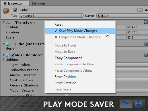
Use the Play Mode Saver from ToddRivers on your next project. Find this utility tool & more on the Unity Asset Store.
Oh and there's a free one as well apparently: https://assetstore.unity.com/packages/tools/utilities/play-mode-save-177452
I thought there was something added to 2020.something but I forget, thanks for the packages 👍
They added a feature to show\run a prefab in a special in-game mode without actually being in playmode, if I remember correctly.
why doesnt my custom function have the gear icon?
ok in unity 2021 thats done through the graph inspector.
Unity UI and MeshRenderers: is there a way to make meshrenderers in a UI hierachy be affected by a Canvas Group alpha value?
I know that CanvasGroup and UI materials use the vertex alpha to make the fading work, but I want that same fading mechanism to work also on a mesh renderer placed in a UI Canvas
Shader graph version 10.0 and up. New in Unity 2020.2
do you know what this error means?
just following tutorials trying to get a grasp of shader graph, hard to debug things that go wrong when you dont know how they work to begin with
@wheat quail Your custom function is expecting a function name of "GetLight_float", but you named in "GetLightingInformation_float" in the file.
ah ok... i had to rename it along the way... ok that puts me on the path
What does the id represent in a compute shader kernel? And what is the difference between the threads defined at the top of the kernel and the threads passed into the Dispatch call?
perhaps this helps
but also i think it's easier to explain like this
if you dispatch (1,1,1) and the kernel has numthreads(8,8,1) you will get id.xy in the range [0, 7] and id.z will always be 1.
so for example if you want to fill in every pixel in a 10x10 image and you've chosen numthread(8,8,1) you want to dispatch (2,2,1) to fill the entire 10x10.
Some of id.xy will be out of bounds in that situation so if you're just writing to a texture you can let it go out of bounds and nothing will happen (out of bounds texture writes do nothing), or you can check if it's out of bounds and return early
if you want to make sure you always fire off enough groups dispatched I use this extension method
public static void DispatchCompute(this CommandBuffer command, ComputeShader shader, int kernelId, int3 numthreads, int3 dataSize)
{
    int3 groups = (dataSize + numthreads - 1) / numthreads;
    command.DispatchCompute(shader, kernelId, groups.x, groups.y, groups.z);
}
just be careful that if you have for example a 10x10 texture dataSize is (10,10,1) not (10,10,0). Maybe there's a better way to do that 🤷♂️ but it works for me
so in other words id will be from 0 to dispatchThreadGroups * numthreads on each axis
Ahhh ok perfect
Thanks!
how can i use the Mainlight shader to setup the material style for the whole game ?
Someone here who can help me with - or explain about - custom passes?
I'm trying to render a specific layer always on top of another layer, but keep all other depth rendering order
this is a limitation of standard decals, they project in one direction so what your getting is correct.
To minimize the problem is to align the cube to the underlying objects surface direction. Where you have a corner of a cube this will be impossible to be correct without distortions.
There are ways clip by angle to avoid seeing the distorted area's but it does not remove the problem as such, just hides it.
The obvious solution here would be triplanar mapping, but that's going to have extra cost performance wise and I've no idea how / if it's easy to do as a decal projector
I see! Thank you very very very very much! Couldn't find the answer online. Your quick reply saved me hours. Thanks
May I also ask how should I enable the effect through script? Toggling activeState?
yea just simply enable / disable the game object, although there are many ways I like to keep it simple myself 😉
@thick fulcrum do you possibly also know how to achieve the effect I'm describing in my question? (I'm trying to render a specific layer always on top of another layer, but keep all other depth rendering order)
(in the HDRP pipeline)
I did the same thing earlier with just rendering 3 cameras on top of each other
but in HDRP i think i need to use custom passes but can't grasp how those work
I'm not familiar with HDRP afraid, but I would probably be looking at camera stacking as the simpler route. however you are probably correct that it requires custom passes in that pipeline.
If you were not trying to keep all other depth order it might be easier in a custom shader, I'm at a loss tbh without using a custom pass
but I've still got training wheels on so perhaps one of the more knowledgeable people will provide a better insight 😉
Thanks for the reply anywayz 🙂 I'll wait a bit more :p
Hey guys, did anyone have an issue where custom shader stopped working when moving scene to addressable? All the other shaders from Universal Render Pipeline, and the ones we wrote in Shader Graph are working when loading the scene as addressable, but the one we wrote from code doesn't, even though we used a template script for URP? It was tested on Android.
It seems like in URP, when making the depth texture unity has all the MSAA data and then explicitly throws it all away: https://github.com/Unity-Technologies/Graphics/blob/master/com.unity.render-pipelines.universal/Runtime/ForwardRenderer.cs#L750

GitHub
Unity Graphics - Including Scriptable Render Pipeline - Unity-Technologies/Graphics
Am I reading that right or is there a way to get the MSAA data from the depth texture?
I was writing some code just to play with a few things (not really production code), and one of the things it was doing was swapping UVs between a few different sets. My main question is whether having extra UVs that aren't used by the shader actually slows anything down. I could store them somewhere else, but the uvs are a handy place to stash them that doesn't require me to create another script, etc. So does it have any performance hit, other than just the (non-GPU) ram it'd take for the extra data?
Are you referring to the fact that bindMS can only be enabled for XR and therefore if you're not using XR, bindMS is false and the texture will always get resolved?
so the UI is supposedly in front of the capsule but the capsule somehow is overlapping it
the capsule is transparent and I've noticed that if I put it opaque it works fine
I'd like to know if there's any way of making it work with transparency
oh, and the blue glass is transparent and is also overlapping the UI which should also be in front of it
Need to use #ifdef SHADERGRAPH_PREVIEW in v10+
rather than #if
Is there an easy way to turn an rgb(3) to an rgba(4) after a saturation node? When connect the saturation node to the color(4) it gives some alpha issues.
You can use a combination of a Split node then a Combine or Vector4 nodes
Bless you! that worked! amazing!
For some reason the entire image is always grayscale, despite the saturation node that is only the lower 1/3. The multiply node comes from a lot of nodes that just multiply together to get that gradient.
Tree without the shader
Tree with the shader
Anyone here have an invisible shadow catcher material that works in deferred rendering, Unity 2019+. Light map bake-able a plus.
I have looked on the forums and came across some older ones (like Unity 5.x), but unfortunately never had any luck using them with my project's version of Unity.
If you don't mind, please @ me in case this gets lost in the channel
EDIT: Built in renderer
^ think of an invisible plane that can receive shadows from other geometry. Kind of like an AOV output you'd get from a renderer for post compositing in something like Photoshop
You can just set any mesh renderer to Shadows Only
Oh, you mean recieving shadows. Sorry, I am assuming you're talking about built-in?
I have used https://github.com/keijiro/ShadowDrawer in the past
I would assume it still works
But it's not deferred 😐
I did come across that and saw the forward only 😔
Hey guys! Does anyone know of a shader that takes in a mask that allows me to change the color of certain parts of the shader?
I'm trying to render a specific layer always on top of another specific layer, but keep all other depth rendering order. Anyone has any tips?
(using HDRP btw 🙂 )
Hey everyone! 🙂 Does anyone know how to access depthBuffer from RenderTexture in ShaderGraph?
Hey everyone, I am pretty new to shaders. Does anyone know why my low poly water works great in the editor, but when exported to webGL only the foam looks good but the ocean part is not rendered?

On the left is my editor, and on the right is my webGL build
Yaaaaaay!
I wish there was a preview node for numeric values
just so I could easily view the output on some equations in graph
Hey everyone! 🙂 Does anyone know how to access depthBuffer from RenderTexture in ShaderGraph?
@solar sinew Remy's node library has "debug value" (and debug int) nodes for displaying a numerical value. The value passed into the Value input has to be constant for every pixel though or the result will be a mess. https://github.com/RemyUnity/sg-node-library
?"
Have you tried the Scene Depth node?
?
for the purposes of deciphering shadergraph code, are VertexDescriptionFunction & SurfaceDescriptionFunction the main vertex and frag programs?
Kind of. The real main vertex and fragment programs are in the include file depending on the master node. e.g. Unlit includes :
https://github.com/Unity-Technologies/Graphics/blob/master/com.unity.render-pipelines.universal/Editor/ShaderGraph/Includes/UnlitPass.hlsl
https://github.com/Unity-Technologies/Graphics/blob/master/com.unity.render-pipelines.universal/Editor/ShaderGraph/Includes/Varyings.hlsl
BuildVaryings is called in vert, which calls the BuildVertexDescriptionInputs & VertexDescriptionFunction functions from the generated graph
and BuildSurfaceDescriptionInputs & SurfaceDescriptionFunction is called in the frag function.
thanks, its really confusing to track down whats what
What does this mean?
Shader error in 'VoxelEngineShader': Program 'CSReset', error X3020: all template type components must have the same type at kernel CSReset (on d3d11)
I tried changing one of my RWStructuredBuffer's into a Texture1D
ah it doesn't like my using a struct for the generic argument
so I'm trying to make a camera effect shader in HDRP using Graphics.Blit(gonna be pushing to a render texture), back in the old render pipeline and URP I can just do tex2D(_MainTex, output.uv) and I can get the color of the screen, but in HDRP I haven't managed to get that working using the new HLSLPROGRAM stuff. Does anyone know what I'm doing wrong?
    Properties
    {
        _MainTex("Texture", 2D) = "white" {}
    }

    HLSLINCLUDE

     #include "Packages/com.unity.render-pipelines.core/ShaderLibrary/Common.hlsl"
    #include "Packages/com.unity.render-pipelines.high-definition/Runtime/ShaderLibrary/ShaderVariables.hlsl"

    struct input
    {
        uint vertexID : SV_VertexID;
        UNITY_VERTEX_INPUT_INSTANCE_ID
    };

    struct output
    {
        float4 pos : SV_POSITION;
        float2 uv : TEXCOORD0;
        UNITY_VERTEX_OUTPUT_STEREO
    };

    output vert(input i)
    {
        output o;
        UNITY_SETUP_INSTANCE_ID(i)
        UNITY_INITIALIZE_VERTEX_OUTPUT_STEREO(o);

        o.pos = GetFullScreenTriangleVertexPosition(i.vertexID);
        o.uv = GetFullScreenTriangleTexCoord(i.vertexID);

        return o;
    }


    // uniform Texture2D _MainTex;
    TEXTURE2D(_MainTex);
    SAMPLER(sampler_MainTex);

    float4 frag(output o) : SV_Target
    {
        UNITY_SETUP_STEREO_EYE_INDEX_POST_VERTEX(o);

        #if UNITY_UV_STARTS_AT_TOP
        if (_ProjectionParams.x > 0)
            o.uv.y = _RTHandleScale.y - o.uv.y;
        #endif

        uint2 positionSS = o.uv * _ScreenSize.xy;

        float4 col;
        col.rgb = SAMPLE_TEXTURE2D(_MainTex, sampler_MainTex, o.uv);
This is the relevant code
Also would there be a way to do this using ShaderGraph instead? idk if Graphics.Blit takes shader graph shaders and how things work there
        var texture = new Texture2D(7, 1, GraphicsFormat.R16G16_SFloat, TextureCreationFlags.None);
        texture.SetPixels(colors);
        shader.computeShader.SetTexture(ShaderIds.CSDoWork, ShaderIds.Colors, texture);
Am I missing a step? In my shader, the colors always returns 0 no matter what index I pick, while the colors I'm passing to SetPixels are all non-zero values.
Texture2D<float2> _Colors;

...

outputBuffer[id.x] = _Colors[0,0].r;
This is along the lines of what's in my shader..
getting an undeclared identifier from a void method(but just using the code from inside the method works)?
Varyings LitPassVertexSimple(Attributes input) {
    // shader spits out "undeclared identifier error" here
    LinearBlendSkinning(input.indices, input.weights, input.positionOS.xyz, input.normalOS, input.tangentOS.xyz, _LinearBlendSkinning_SkinnedPosition_3, _LinearBlendSkinning_SkinnedNormal_4, _LinearBlendSkinning_SkinnedTangent_5);
}
//
void LinearBlendSkinning(uint4 indices, float4 weights, float3 positionIn, float3 normalIn, float3 tangentIn, out float3 positionOut, out float3 normalOut, out float3 tangentOut) {
    <stuff here>/*, if <stuff here> is pasted into the above directly, theres no error and everything works*/
}
is it possible to use one shader script in tthe Global area ? the shader just do an Cel Lighting. problem is logical if i attach it the onject is white because i want to texturize the object by my own .
Hey guys! does anyone know why fog is not working with this shader? ```Shader "Unlit/Invertex/UnlitMaskedTint"
{
Properties
{
_MainTex ("Texture", 2D) = "white" {}
_Color("Tint", Color) = (1,1,1,1)
_MaskTint("Mask Tint", Color) = (1,1,1,1)
}
SubShader
{
Tags { "RenderType"="Opaque" }
LOD 100
    Pass
    {
        CGPROGRAM
        #pragma vertex vert
        #pragma fragment frag

        #include "UnityCG.cginc"

        struct appdata
        {
            float4 vertex : POSITION;
            float2 uv : TEXCOORD0;
        };

        struct v2f
        {
            float2 uv : TEXCOORD0;
            float4 vertex : SV_POSITION;
        };

        sampler2D _MainTex;
        float4 _MainTex_ST;
        float4 _Color;
        float4 _MaskTint;

        v2f vert (appdata v)
        {
            v2f o;
            o.vertex = UnityObjectToClipPos(v.vertex);
            o.uv = TRANSFORM_TEX(v.uv, _MainTex);
            return o;
        }

        fixed4 frag(v2f i) : SV_Target
        {
            float4 col = tex2D(_MainTex, i.uv);
            float mask = col.a;
            col *= _Color;
            return lerp(col * _Color, col * _MaskTint, mask);
        }
        ENDCG
    }
}
}```
folks, is it possible to use the color property value of a sprite renderer in a shader graph?
similar to how _maintex works
okay, I've done it 😄 reading vertex color works
@solar sinew I want get it from render textures.
Is it possible to identify the data of an async GPU readback request somehow?
For example, I am requesting data every frame (in an editor tool) and I am using the same readback action to handle the request result. However I have to interpret the result differently for every frame as the data is for different parts of the map. Therefore I need to be able to send some additional parameters along with the readback request to identify it. Is this possible? Thanks for the help!
Alternatively it would be enough to know whether the request order is guaranteed, as this would allow me to keep track of the requests in a separate queue, however I can't find any information on this online
If you're using a Queue<AsyncGPUReadbackRequest> to keep track of them, It would probably be possible to swap AsyncGPUReadbackRequest out for a struct or custom class containing the request with other data.
... I am stupid af. I just realized that AsyncGPUReadback.Request returns the the AsyncGPUReadbackRequest and I can simply compare it to the one I am getting as parameter in the callback. I wasn't paying attention to the return value of the request function, I thought it is void.
Thanks! 😂
When using normal to height its not possible to connect to the normal node. Does anyone know why?
It cannot be connected to the "Vertex Normal" as the Normal From Height node uses the partial screen derivatives (ddx, ddy) to calculate the normal. (These are only available in the fragment stage of the shader)
It should be connected to the fragment's version of the normal instead. On the PBR Master or HDRP Lit, it's the "Normal" port.
(This defaults to Tangent space, which means you should use the Tangent space option on the Normal From Height node. It's possible to change the space on the master node if World is required for other calculations though).
aha, so If i make a custom node that returns it to world space it would work?
No, it can't ever be connected to the Vertex Normal port. Use the other Normal port instead. I've edited the above to try make it clearer
how can i change texture size in material ?
quick question
does anyone have a unity standard PBR shader that seperates the transparency and albedo into seperate maps?
i wanna UV Animate the albedo layer but not the transparency
I mean, you can just split node it and feed your albedo and alpha with whatever you need
oh, could you show me how to do that ?
You should show, what you did so far in the pbr shadergraph 😉
oh, i haven't made any changes yet.
Ohh okay. Well, I advice you to just install shadergraph if you are using URP or HDRP and just go through a simple tutorial, you will understand it quickly 🙂 Its just node based drag dropping tbh
whats the use of the GPU Instancing checkbox?
it looks like i can instance materials while it's turned off
sorry to interrupt but does anyone know how to get rid of this seam in a PBR graph shader
I think you can then change values on every material sharing the same shader, but you should read the docs rather asking me 😉
looks like your noise is either not repeatable or your UVs are not set to the right ones
how do i offset it to make it repeatable
It is not possible with the shader graph node, you might just create / download your own texture and use that which is tileable @lapis hull
@digital gust i figured out how to create a surface shader that does what i want :)
Wasn't that hard, right? 🙂 Shader graph is quite easy to understand and fun to play around with 🙂
Ohh okay 🙂 In the end, shader graph is just a visual editor in Unity to create them without writing the code. But your issue was not too complex 🙂
what can i use to make my shader completely transparent when the alpha is at zero?
right now there's a funky black colour left behind
i tried noshadows and noambient those didnt seem to do anything
the rendering mode is fade
looking at the render queue, it suggests your using opaque rather than transparent...
perhaps try doing it as transparent render queue 3000 + or alter the shader code.
you will just lose some z sorting as transparency does not write to depth by default.
ah, that fixed it, thank you :)
graphics are weird.
i don't remember what math functions and things i have access to in shader code...
I need a min()
wouldnt procedural generated noise displacements not work on spheres at all then using shader graph??
yes
Why is "Overlay" the default mode of the Blend node, and not "Overwrite"?
I don't even understand what the hell it does.
void Unity_Blend_Overlay_float4(float4 Base, float4 Blend, float Opacity, out float4 Out)
{
    float4 result1 = 1.0 - 2.0 * (1.0 - Base) * (1.0 - Blend);
    float4 result2 = 2.0 * Base * Blend;
    float4 zeroOrOne = step(Base, 0.5);
    Out = result2 * zeroOrOne + (1 - zeroOrOne) * result1;
    Out = lerp(Base, Out, Opacity);
}
Obfuscate much?
Beautiful lensflare. Is it geometry or post?
the lens flare is post, the flame is geometry
I need someone to point me in the right direction. I have this toon shader and I like the dark shadows it makes during the day, but at night if the player is being lit I want the dark side to be slightly visible and not just a silhouette.
also its all material animation, no modification of the mesh
I personally never use the Overwrite mode anyway, it's exactly the same as a Lerp node so I just use that.
The blend modes should be the same as software like photoshop, so there are probably tutorials that show what they do / look like from a non-code perspective.
Ah yeah Photoshop.
Probably that's why such an obscure algorithm is default. It does look nice, but also totally wrong to someone used to Lerp the crap out of everything.
Glow and Screen and stuff never made sense to me, not even in Ps.
Yea same, I haven't looked into them that much and never really use blend modes.
Nice, I really like it.
Hmm, I'm looking for something that doesn't really exist 😉
I'd like to spherically reverse-project screen positions from the camera view direction so any way the camera moves, it looks at an infinite flat plane.
I think I need to project something onto the near plane but I'm not sure.
Basically a world position offset for Screen space. If that even makes any sense. (it doesn't exactly with perspective correction, but it only needs to be reasonably accurate at the screen center.
I am working on a halftone mixed lighting system but the stippled channels look awkward especially if the camera moves.
Because basically the object moves through a field of these stipples. I've checked some movie references coughspiderman and there they just put the hatching into Object space, which of course doesn't quite work for anything that isn't a movie where you have perfect control over where something ends up on the screen, and where it is gonna move.
It actually looks ok at 30 fps maybe this is my life now.
(I want to set 120 fps as the target framerate for my game actually, but also want to mess with animation on "twos", which for me would be on... eights or tens)
Triplanar projection could work but it gives me very limited control over the screen space side of things.
if there like an emission node in unlit shadergraph or something I can use to make my character emit light?
does making colors hdr make them emissive?
No.
But HDR colors in fragments may be picked up by post processing effects, such as bloom.
If they are beyond the threshold.
ok i think i get wat ur saying now
Emissive colors are really just "unlit", so your entire graph is emissive. If you do any lighting calculations in it, then you can just mix in the parts that are supposed to be "emissive" in the last step - by adding them to the final color.
Don't saturate() the final color though, you usually want it to be able to go above 1.0 on the glowy bits so you can bloom the heck out of them.
So happy I got a sharp and a smoothed normals channel... now I just need to find our how to change camera angles or angle deltas into an affine transform (for tiling and offset)
I'd rather do this without a global shader parameter.
I'd also like to not add another texture lookup, there are gonna be plenty 😄
Is URP's Clear(Z+Stencil) event functionality defined somewhere in the lit shader? Im trying to fix ssao in my shader(which is largely based on URP lit), and the one difference when viewing with the Frame Debugger between it and the bultin lit is that in the Clear "event" clears the ssao effect from my shader but not lit
Hi everyone. Can someone help me ? I'm trying to replicate this shader from the tutorial. The tutorial is being made in Unity 2019. My project needs to be in 2020.2.f1 URP. I think there might be some compatibility issue. I can't make the "Get light data" script to work. I get the pink checker.
https://blogs.unity3d.com/2019/07/31/custom-lighting-in-shader-graph-expanding-your-graphs-in-2019/

Unity Technologies Blog
With the release of Unity Editor 2019.1, the Shader Graph package officially came out of preview! Now, in 2019.2, we’re bringing even more features and functionality to Shader Graph. What’s Changed in 2019? Custom Function and Sub Graph Upgrades To maintain custom code inside of your Shader Graph, you can now use our new Custom […]

GitHub
Some custom lighting functions/sub-graphs for Shader Graph, Universal Render Pipeline - Cyanilux/URP_ShaderGraphCustomLighting
some things have changed since 2019 and I'd look to Cyan's custom lighting examples to compare the code
ahhh this is what I was thinking thanks I'll review these scripts to see what was changed. I believe some of the global variables have changed like "getmainlight" for example don't exist in 2020 anymore.
GetMainLight still works
you might be running into some compatability issues between the old tutorial and shader graph 10.0
using an unlit shadergraph. how do i get a normal map to work in unlit?
im guessing i have to plug them in somewhere with lights
thanks! didnt know that
have you seen Mixture? I know it uses some subgraphs from the surfgrad framework. Check out some of the subgraphs here, there are a lot of operations
https://github.com/mmikk/Surfgrad-Framework-Unity-Shadergraph

GitHub
This is a sample scene made with Unity which includes a folder of subgraphs, for shadergraph, of the surface gradient based bump mapping framework. This is a new framework which allows you to do la...
either way, this is the normal map subgraph I use
Thanks a lot @solar sinew
dane, do you use that normal subgraph in an unlit shadergraph?
Thank you.
Currently wrestling with... every fragment normal being the same, wtf.
Arrrrgh
Hit undo after apply somewhere.
I'm trying it out now, I think usually what I do is have my normal map as part of my lighting calculation that then gets output to fragment color.
trying to remember... I personally haven't used vertex normal much
I think usually you would just input whatever UV you are using into the sample texture node and include that somewhere in the calculation that gets output to fragment color
i'll look into fragment color. not sure what that is
sorry
base color
it's in the fragment section of the master block
I've been jumping between 2019 and 2020 for different projects so apologies if I get mixed up anywhere along the way
well as long as i know its possible i'll dig up something in google eventually
you are just trying to include a normal map?
ya
oh also here is the link to Mixture: https://github.com/alelievr/Mixture
I had just linked you the framework of subgraphs it uses. The tool might be to your liking
GitHub
Mixture is a powerful node-based tool crafted in unity to generate all kinds of textures in realtime - alelievr/Mixture
interesting
okay back to normals
This is how I use a normal map for an unlit graph
then after the main light is whatever else you are doing in your shader
@wheat quail
thanks. i'll try to replicate. so the first pic is a subgraph and the second is that subgraph in the main shader?
yeah (there are actually additional layers after that but that's irrelevant 😅 )
the first is a subgraph, which contains the normal map subgraph
aka MainLightUnlit
then I input the sample texture node into the MainLightUnlit node
Question: I have values from 0 to 1 of something.
How do I do something to the lower 25% and something else to the higher 25% of these, for instance?
Multiply by 4 and and saturate and subtract 3 and saturate respectively?
try the remap node
This shaderforge contour map shader I remade in shader graph could be useful reference for applying something to specific ranges using modulo and step
#archived-shaders message
I don't quite understand why you do it that way but I like the shader idea 😉