#archived-shaders
1 messages · Page 180 of 1
ok, i think this will work, thx!
hope so ^^
@spring fox did you turn the value down to something low, like 0.01 or something?
your just adding it to your albedo or is that a direct feed?
could be some HDRP quirk I'm not familiar with, I avoid it if I'm honest just working in URP myself.
Perhaps someone more knowledgably on hdrp can step in
Time.time is different from Time.y in unity shader, correct?
why have my shader particles suddenly turned into squares? .-.
_Time.y-_StartTime --> it is not zero, sometimes!!!
material.SetFloat("_StartTime",Time.time)
Weapon skins, thanks
@meager pelican Texture animations like texture sheet is heavy. They are not animated textures, I think
Looks like animated textures to me. They're scrolling/deforming the texture over the surface of the material (probably an overly type of thing to the base texture).
Try putting a texture on it, and then playing with the offset and tiling in the material inspector once to see what happens. It will "scroll" as you adjust it.
@toxic flume
Or you could do a flipbook if you want to be all cool 'n stuff. Signed distance stuff maybe too. All sorts of things.
That's you programming. 🙂
But your model has to have the UV's set up right for it, as in mapping the texture pretty "flat" over the model. Could be a different UV set from any "base" if you want to overlay.
But it doesn't have to be a flipbook sheet, if that's too much memory.
All depends on your needs and target platforms.
Are you sure it is as easy as only scrolling uvs?
Because it scrolls in z local axis and not uv. You mean it is only uv scrolling?
I have created it before. It is in object space not uv.
Isn't object space or even screen space standard for weapon skins?
So I need to have standard flat uv for it, right?
You could create a second UV channel specifically for this
It would have to added to every weapon mesh though
Perfect. My question is "do I have to have different uvs for different skins or only a second uv channel which works for different skins"
Those videos look object space to me though
Yes I think so
If I can achieve these effects without additional uvs or flipbooks, it will be awesome, like dissolve, distortion and math calculations.
One question here, is it possible to apply shaders for buttons in main menu? Because in preview it works, but when i press start it not shows. I want to use holograffic effect that i created before and it works on game obj, but in UI it works only on background and text, but for some reason not for buttons :/
@toxic flume Dont forget to charge an exorbitant fee to access those cool animated skins, because it took you ages right XD
Jabbing at the industry aside, they look cool, nice one!
You could just do a Star Citizen and charge $32,000 for it 😛
Could someone help me with my shader? I made a dissolving shader and I want it to activate when something happens in the game, but when I switch to the material where the shader is, it is already running in the background and I want it to start when I need it. So I need something that prevents the shader running when its not active if you understand what I mean
@dusky mountain Yes I got it.
One solution is to set start time using material.SetFloat("_StartTime",Time.Time) and sent time to your shader as start time.
In your shader, probably you have something like below
(_Time.y-_StartTime) //frac,sin,etc.
//For example: _Amp*sin(2*PI*_Freq*(_Time.y-_StartTime))
One problem is _Time.y sometimes is different from Time.Time, I think. I do not know why.
Maybe you should use Time.TimeSinceLevel ...
it's my first time dealing with shader graph so I'm kinda lost xD
material.SetFloat("_StartTime",Time.Time)
It resets your timer.
You write it in your c# script not shader.
ah ok
yeye
but
do I connect the script only with the gameobject where the material is?
If you do not want to reset your timer (start from zero), you can set an int (1 or zero), for example.
Then get it in your shader and use step or multiply operator to do different things, activate, deactivate,..
public class YourClass:MonoBehaviour{
   public void ActivateShader(){
      _material.SetFloat("_StartTime",Time.Time); //or
      _material.SetInt("_ActivationFlag",1);
   }
//...
}
It changes your material. Maybe you use a material for a bunch of gameobjects. It depends on your code and design
Yes, you can have two different materials and switch between them when a specific event occurs.
You said your problem is about timer and I suggest reset it, if you want!
yes
thats what I want to achieve
public void collision()
    {
        collisionMaterial.SetFloat(0, Time.time);
        player.GetComponent<MeshRenderer>().material = collisionMaterial;
    }
like this?
idk xD
my water shader turned out to look rlly good when i made an ocean
Is there a way for sprites to cast shadows on 3d objects in URP?
And if so, is it possible to achieve that with shader graph?
Simple question: why does a vector 2 in the blackboard always show up as vector 4 in the inspector?
in URP*
Because materials technically only support Vector4 properties. Lower vectors just omit the components they don't use
Normally shaders only have an option to expose a property as a "Vector", which has 4 components. Shadergraph just provides multiple options but Vector2/3/4 are all considered a Vector.
Perfect explanation thanks. It's a small annoyance but I wish the inspector would omit these components not being used
Is there a way for shaders to "unbend" an existing image?
Can someone point me in the right direction?
So, on the left is the "original" image, and I want to unbend it. This can sorta be done by bending the image in the opposite direction. So maybe the question can also be "is there a way to bend an existing image"?
I would specify a "center" point for the bending, the left and right dots. Is there a name of an existing algorithm I could reference/research?
nvm Ill just check out these tutorials: https://www.youtube.com/watch?v=C0uJ4sZelio&ab_channel=quill18creates

Make sure to SUBSCRIBE so you don't miss a video!
Download the complete project: http://quill18.com/unity_tutorials/
Also, please feel free to ask lots of questions in the comments.
This channel is mostly all about game programming tutorials, specifically with Unity 3d. You ...
Hey everyone, so I figured that in order to make "volumetric" shader for my atmosphere to be looked from the inside I needed to make a post processing and add it to the Forward renderer of my Pipeline, however post processing is applied for every pixel of the screen, so my question is is it possible to draw a sphere where the post processing will be applied? I've tried using Sphere mask as well as a Freshnel effect but none of those work, also is it possible to specify an object position? For now my camera is centered to the planet but I'll eventually need to move the camera and not just rotating it
@mild mesa sorry to ping but would a texture mask be able to solve my issue? Also is it possible to have a texture map applied to an object position?
yes i fixed it
mate your on like level 9000 and i am on like level 7
when it comes to writing shaders i am still on shaderlab code and it takes me like 3 days to do a mask and even then i copy and paste and swear alot
Lmao I'm new to shaders to but I use shader graph, if I find a way I'll probably post it here, thanks anyway
sorry buddy, im not very good at this stuff hence i came here... i am now struggling with reading a texture created at runtime now.... I want to get the pixels out of the texture
Sample texture 2D from _MainTex?
yeah
? So what's the issue?
is _MainTex the final texture ? i using perlin to make that texture and then i am applying an mask...
_MainTex is the textures displayed on screen
No matter what you did before _MainTex will always return the final screen pixel display
what is happening is it is returning alpha = 1 for all the pixels so i am assuming its not grabbing that final texture
Apparently for my issue I could use Post Processing stack V2 and apply a layer to the objects I wanna post process
?????
You know what alpha is right?
there is no color in the corners in the screenshot
Thus returning 1 since your skybox is not transparent
i am reading the texture from the material though
does that not focus it down to that only?
Ah alright
so im pulling if from another object
Let's keep it simple what you wanna do exactly
ok, im using perlin to make a texture, then i am using the shader to add the fade to alpha towards the corners.... then i want to read that texture to sample it to say this is where the land is, then create land where there is black or white and fill alpha with sea
What
essentailly i just want to read the texture but it seems tricky
so here is my terrain
it looks like perlin noise, i want to make the land mass only created in the middle
okay
so i am creating a texture with perlin, then i am using a shader to exlude if from reaching the edges, then i am wanting to read that texture and use its sample to say this is where to put "land"
you are trying to create a minimap or something?
because their is waaay easier that creating a shader
no.. but i could use that as a minimap also
okay
the shader is done... im stuck on reading the texture now
show the code
or your nodes or whatever you are using to make the shader
pastbin is more appropriate
kk
Pastebin.pl is a website where you can store code/text online for a set period of time and share to anybody on earth
line 46 i am trying to get the pixel array
can I see your texture?
I assume you put it as a 2DSprite right?
and not the default settings?
oh okay you are trying to get the alpha from the generated texture from this quad?
yes
im trying to read all the pixels, if i have 0 alpha, that can just be water etc
black can be water ( lakes )
white can be ground
maybe try to get the alpha directly from your texture mask?
you can even make a condition that says if the texture is black then it's ground otherwise it's water
yeah good call
wait how do i grab that "Culling Mask"
.GetTexture
all good
mate i think that just might work
uh uh?
thanks bro i am going to implement this the now... I hope someone can help you with the shader issue you have
i will come back and show you my results
out of intrest whats your volumetric shader issue look like?
I'll show you

So my issues are the following :
#Issue 1
When the player look at the sun, if the atmosphere's mesh is on the way, the sun won't display the bloom effect (From the volume script provided by URP), this can be countered if I decrease the transparency of my shader which is not...
here
I tried to make a shader applied to a sphere collider to make a shader atmosphere
everything is good aside from 2 thing, I can't see my atmosphere from inside the collider
the sun doesn't bloom if my collider intersect with it
so I tried to make it a post process effect so I have that effect no matter where my camera is, it solves the 2 issues I have but now this effect is applied everywhere
I'll record it and send the video for the post processing
that looks pretty cool what are you making?

Here is what I have for now, but I would need my post process to happen only arround my sphere and where the sun enlighten the planet's face
A Spore game
in ECS
that looks really epic man
not that much since I'm stuck
I litteraly just need a mix of both of those for my atmosphere to look decent
I can't understand how something that simple in concept is so difficult to do
I tried to look at how to make a shader for water that also applies effect underwater but even that I can't find
Also I think the post processing effect is a wrong approach since getting the position of the planet would be too complex, as well as getting the litted face of the planet
and Finally I'm fucked if I try to display 2 planets or more, so I guess I'll try and stick to a normal shader? but how the hell can I make it volumetric is another deal
if anyone can give me a clue of how to manage to do that i'll be gratefull
Hey everyone :)
Quick question. I have a compute shader I use to generate an image, and I Graphics.Blit this to the camera. I want to introduce depth however so I can render objects on top of or behind this image (or a combination).
What do I need to do to allow me to write to the depth buffer of a render texture, and influence that in my compute shader?
@stone night May I ask why you need to be able to do this?
Basically my end goal is this:
I have a ray tracer which renders the world
I want to render things like meshes that can get occluded by ray traced geometry
@low lichen
What about doing the opposite, rendering normal geometry first and using the depth from that to occlude the ray traced geometry?
I'd imagine you would be able to save more resources that way, because you could skip some of the expensive ray traced surfaces if they are occluded.
@stone night
That works as well.
Come on guys, nobody?
Come on guys, nobody?
@grand jolt im not very experienced with unity but i know that when i had to make water in ue4 i just took a plane with a texture in it and then put a post process volume under that oh and i think Sabastian lague has a video on atmodpheres
there is a GitHub attached so you could research that
Yes the planet generation I have is based on Seb's work
But I had to use shader graph because I want to turn my project into an ECS project
And has far as I'm concerned I couldn't use Post Processing the way Seb did to render my entity
But your approach is actually interesting
I guess I could try and use the post processing I have coupled with the shader on the mesh I have
I could then try to use a sphere collider for the volume so that when the camera enter the collider it will automatically switch to an "atmosphere" view
nvm 😄
@grand jolt post processing is probably simplest route, use the PP volumes to switch it on and off. Or make your own volume with a sphere collider to trigger the code switch
@thick fulcrum making my own volume with a sphere.... Interesting, any lead on how could I make this tho?
I think it could be a better way than coupling a shader and a post processing shader
I want to make it as effective as possible and I know I'm not going to like coupling two effects
two ways, one is to just use a sphere mesh collider, you just don't have a renderer on it.
The other is to have a physics sphere cast, probably from the planet running in lateupdate which could be the trigger
Interesting, could it be seen from outside the collider sphere tho?
Oh and by the way many thanks for not ignoring me and trying to give me leads, we need more people like that
What I'm frustrated with is that the atmosphere from the outside is sooo perfect, only the inside doesn't render, I wish there could be a way to render a shader from the back faces
it's just a collision for the camera, without a renderer its' not visible. just to trigger switching the PP on and off as you surmised yourself 😉
You know what, that actually might cut it, I'll try that later and thanks again dude!
you can render back faces too, and branch to give different shader effects depending on if front / back face seen
BUT as at some points you will see both front and back this will cause culling issues, so perhaps not ideal
Yeah I was going to say that rendering from the back face wouldn't be good actually
Because the "fog" or volume or whatever you call it would be renderered from the outside, so when you'll look at the sky it would have that fog (good because I want the sky to take the color of the atmosphere) but the terrain itself would not have that fog
I'm gonna stick to the volume PP with a trigger in it for now, many thanks again, you opened my eyes
Hi, I'm trying to do some custom lighting shader with Unity 2020.2. In the shader graph i have thi error. Anyone know why?
this is the code
and this is the error
@west knoll Use #ifdef SHADERGRAPH_PREVIEW instead of #if ...
Also shouldn't need the 0 in the GetMainLight function. Just GetMainLight() should do.
I've got some lighting functions + subgraphs here if it helps : https://github.com/Cyanilux/URP_ShaderGraphCustomLighting
@spring sorrel You should remove the Absolute World space Position node. The Vertex Position input expects Object space. If you leave the input blank it'll automatically handle that. You only need the node if you want to offset/scale it.
yeah i removed it and i still get the same problem
Make sure you are saving the graph with the Save Asset button in the top.
If you're doing that, Then I'm not sure. You might need to provide some more information about how it's set up. Maybe try different textures to test what it looks like, to make sure it's not a problem with the texture.
alright
I am having trouble understanding what [numthreads()] and Dispatch() should be in relation to each other for a compute shader. I've looked at the diagram here: https://docs.microsoft.com/en-us/windows/win32/direct3dhlsl/sv-groupthreadid but I feel like that made me a bit more confused, as I kind of understand what each ID type means, but not how they should match up.
Indices for which an individual thread within a thread group a compute shader is executing in.
@silver bronze IIRC, you want to dispatch the total # of threads to process what you need to process, and you'll have to know that quantity. Could be some actual value, or some max value. But that is used by each thread to select an index to process, yes?
So if you use numthreads(8,8, 1) they'll be run in an 8x8 "grid" so in 64-thread-chunks called the WORK GROUP SIZE. What you pass to the Dispatch() call is how many of these work groups you want to do in xyz.
And then you'd dispatch the shader, and the threads would have to check that they don't exceed any actual-value index. Per the docs:
This functions "runs" the compute shader, launching the indicated number of compute shader thread groups in the X, Y and Z dimensions. Within each work group, a number of shader invocations ("threads") are made. The work group size is specified in the compute shader itself (using "numthreads" HLSL attribute), ***and the total amount of compute shader invocations is thus group count multiplied by the thread group size***. Work group size can be queried using GetKernelThreadGroupSizes function.
From https://docs.unity3d.com/ScriptReference/ComputeShader.Dispatch.html
Catlike Coding just did a thing on compute shaders here that may help too:
https://catlikecoding.com/unity/tutorials/basics/compute-shaders/

A Unity C# Basics tutorial about using a compute shader to make it possible to show a million moving cubes.
@west knoll Use
#ifdef SHADERGRAPH_PREVIEWinstead of#if ...
@regal stag Thank you, it worked!😁
So if you want to use numthreads(8,8,1), then divide your total # of needed threads by 64, round up if not even, and then make sure each thread checks that it hasn't exceeded the max index value and only works on proper memory addresses. Don't access out of bounds stuff in shaders. "It would be bad".
So basically Dispatch is like the amount of iterations for each thread?
or "tasks" you give each one?
Let's say you have a buffer of 10,000 things to process.
You know it's either exactly 10000 or you know it's max=10000 regardless of how many are flagged "active".
Whatever. However you design it.
So if you used numthreads(8,8,1) in your shader, that's = 64 threads in a group. So that's the min group that will process. I've seen people use 1,1,1 but IDK how efficient that is. May depend. Anyway, see tutorial.
But the point is that 10000/64 = 156.25 so you need to round that damn thing up to 157 dispatches of 64-thread workgroups. And make sure to not read off the end.
So you dispatch, I suppose: Dispatch(KernelID, 157, 1, 1);
That's one way.
Or if you're processing a set of rows and columns in two dimensions, then you could use something like multiple dimensions for whatever reason.
This is all off the top of my head, so grain of salt and go ahead and check out that tutorial.
🙂
It's a weird design with two sets of multi dimensional parameters, which is kind of odd IMO. Particularly when GPU hardware core counts vary.
And how you do it impacts what you get back in the various ID variables inside the shader.
So numthreads() in the shader defines the # threads in one group, dimentionally. And then the Dispatch says "how many groups to run", dimentionally.
So I'm confused, why are you putting all 157 in the first group of Dispatch, but have two groups of 8 in the numthreads?
wouldn't it be better to dispatch with ceil(10000/8),ceil(10000/8),1?
Sure, do that, it might even be more efficient. Depends on needs and what you want to get back out of the various ID variables that it "counts" for you. So in your example, you'll pay attention to both the .x and .y values of the dimensions. GroupID, threadID, etc.
But in the end, and this is where I'm fuzzy, if it knows it's got 256 cores, and a group size of 64, does it actually run 4 groups at once to max the cores out? Or not. I don't recall, if I ever knew.
So as I said earlier, dispatch is basically telling each thread how many things/iterations it has to compute, if I'm understanding correctly
which is why you are dividing the total by the number of threads
Well, terminology. Each "thread" is invoked once, and only once, but you'll have over 10,000 invocations.
So there are 10000 threads just grouped up by groups of 64?
In the end, yes. Run in batches of 64 or whatever. Maybe groups of 64.
That's why each kernel is written as one "thread" and gets its variables for its invocation.
Massively parallel threads.
okay
do you know any actually good documentation on compute shaders?
because I have yet to find any
Nah, maybe someone else does. I just "work it out" from what I said above. But if you find some, please post it.
That Catlike Coding tutorial isn't bad, but it's only one use case. There may be some more that come up with web searches for "GPGPU" if you want to try that.
And probably some e-books on gpu computing.
Okay thanks
Is there a way to categorize shaders made with Shader Graph? Add them to a sub-folder such as 'Shader Graphs/My Project'
You mean in the project hierarchy? Can't you just make a folder and drag/drop the shader into it?
Or do you mean in the shader list dialog?
In the shader list in the inspector
See last post:
https://forum.unity.com/threads/how-to-change-the-shaders-menu-name-using-shader-graph.563395/
Try that. 🙂
Unity Forum
In regular shaders, you can set the shader's menu name with:
Shader "Custom Shaders/My Shader"
I can't figure out how to do the same with Shader...
Omg it was that easy. Didn't look like that piece of text was interactable at all
Thanks! 😄
Hey guys, I have a panoramic shader I'm using for over/under stereo 360s, but there's an issue where at the lower pole (looking down) the texture seems to crunch in on itself:
https://hastebin.com/aqabohoqot.cpp
It's hard to tell if this is due to the render setup or the shader but thought you guys might have some idea, here's a screengrab of the messed up poles (from an alternate angle as it's not super obvious from viewer POV)
Also with the shader I'm pretty sure its just built on the standard unity pano shader, but with more properties exposed (in fact I think the custom editor it references doesnt exist so it just exposes all the properties but this is what I needed anyway)
If it helps my image is a 5000x5000 jpg
Sphere mesh or no?
If so, maybe try an icosphere that doesn't "merge" verts at the poles.
Ah yeah it is a sphere mesh, just started reading elsewhere that this could be the issue, I'll give it a try!
@meager pelican I've tried a few different versions of spheres (ico, tetra, octa with varying levels of detail, none of them seem to change the final result (aside from vertices slighly differently positioned)
Same result with 64 seg ico sphere
Would this suggest to you that it's an issue with the render output over the shader?
Or just a guy falling quite fast onto earth
You should not use spherical mapping I think, like update the UVs, so they do not get stretched this way
Hmmm how to determine why I can't put the output of one node into the Vertex Position input of PBR Master?
When I drag the output and create a new transform node it sets the input to Object and Position, so it should be Object space, which the Master wants
(It's a vector3 too)
Some nodes can't be connected to the Vertex stage. Mostly the Sample Texture 2D one. Use the Sample Texture 2D LOD instead.
DDX, DDY, DDXY and the Is Front Face node are also one's that can't connect to vertex stages.
Hm
If that node is in the chain it'll prevent it from connecting
Yeah, Scene Depth also can't be connected to the vertex input as it uses a texture sample internally. It could likely be swapped out for a custom function if you really need it in the vertex stage
Just figured it would be a good way to lessen the effect in shallower areas
But makes sense
Will try around, thanks
@vague pike I think using something like this in a custom function would work :
TEXTURE2D(_CameraDepthTexture);
SAMPLER(sampler_CameraDepthTexture);

void SceneDepth_float(out float Depth){
   Depth = SAMPLE_TEXTURE2D_LOD(_CameraDepthTexture, sampler_CameraDepthTexture, uv, 0).r;
}
Might not even need the first part declaring the depth texture if you're already using the scene depth node in the fragment stage too.
i am making a realistic like game guys,where should i start to learn shaders? help your bro
Hmm I thought it was a logical thing that you can't use Sample Texture 2D LOD, since the vertex stage comes first. How does that get around it?
The LOD one can be used in the vertex stage as it just allows you to select which LOD (aka mip map level) to use from the texture.
You can't use the regular one as it calculates the mip map level instead, using screen space derivatives (like the DDX/DDY/DDXY nodes), and that can only be used in the fragment stage.
@digital gust I don't know much about shaders, if you mean to adjust the UVs in my 3d package - the uvmapping seems to be totally within the shader
I took a shot @limpid tulip, but other than that, IDK without the source. At least you eliminated a possibility. Cube mapping and cubemap assets are supported in SG, but...that's all I know.
Oh wait, you showed source, and it's built-in. Hmm. And you used a cubemap.
Hmmm
Another thing is, I've tried a water shader tutorial. It simulates refraction by basically shifting the screen position around with a bit of a normal map made from noise
And then passes that to scene colour for colour. And issue with that is, that objects in front of the water also show up in the refraction wobble. Rather than stuff usually not seen. Is there any way to fix that? Or would one need proper raytracing instead of simulated refraction.
As an example. I turned the strength of the effect way up to show it better, but it's there otherwise too, just more subtle. You can see the at the top of the purple crystal it, the water acts as if it refracts that too, even though the crystal is above the water. I feel like there proper refraction would show parts behind the crystal instead - that would usually not be visible.
@vague pike scene color should just be the scene / objects which are opaque behind the transparent water plane. sometimes it bleeds to those infront if values are a bit high
@thick fulcrum Hmm, I thought it's just basically an image of all the things rendered without the object in question (at least if the object in question is last to render, I suppose opaque stuff is rendered first.
How can we decide a common general shader is more performant or different shader with different simple behaviours (more drawcalls)?
@meager pelican Yeah I appreciate the help Carpe, just trying to figure out what could be causing the issue, still don't know for definite if it could be the render output but that's a bit harder for me to test right now as I'm not the one outputting the renders and have no idea what possible settings would need to be changed, whole other kettle of fish haha.
There are ways to help fix that yeah. You can test the depth of the distorted pixel and if it's greater than the surface depth of the water you can just use the "undistorted" scene colour.
Oh right
Via scene depth
@regal stag Though that won't be able to show parts in the refraction that otherwise wouldn't be visible, right?
For example, I can implement a dessolve shader with rotation ability and use it in different situation (one shader)
were you get double exposure sort of issue, you need to avoid double transparency by just using scene color node. damn I can't explain very well, maybe someone else can 😆
I think this is just an issue with how the shader does refraction, but not sure
@vague pike Yeah, that's why if the distorted pixel would be above the surface we just use the undistorted one instead, which we know will be below the surface but might not be visually correct.
I have a tutorial that uses this method, might be a little dated but should help explain it : https://cyangamedev.wordpress.com/2019/06/10/water-shader-breakdown/
@limpid tulip Did you try some other "stock" cube map and uses it all as a standard built-in pipeline skybox?
@regal stag I see, shame. That'll be one of the nice parts about raytracing I guess
Does it do the same thing with this stock shader?
Good suggestion carpe, I don't have time right now to test it but I'll give that a go later on.
Good luck, I obviously don't know a pat answer. I mean, it might not be a bug, just an undocumented feature.... 🙂 😉
I have a URP shader graph with specular texture assigned for a gloss effect. In the shader graph editor it works correctly. In scene and game mode, the gloss does not appear regardless of orientation.
I'm using a single directional light in the scene.
All other aspects of the shader work correctly. What am I missing?
@high hemlock Because you're sharing the same vertices for multiple faces
The normals of a mesh are stored with the vertices and a vertex can only store one normal
When a vertex is shared to make 3 faces all with different normals, the best it can do is make a normal that is between all 3 normals
@high hemlock Why do you have to make a new cube mesh for every block you spawn? Why can't you reuse the same mesh?
playing around more.. it looks like the specular view direction shader portion IS working in scene mode
just not in game mode. changing lighting angle/object angle doesn't render specular texture.
For the voronoi node, anyone know how to get the distance from a cell's center to it's border in graph?
@solar sinew I've got a post that goes over some custom functions for "voronoi edges" : https://cyangamedev.wordpress.com/2019/07/16/voronoi/
Awesome
@regal stag Nice tutorial. It does have an issue too, which I'm not sure is fixable either. It now cuts things off that shouldn't be cut off.
Though maybe I can do some magic with position or something to fix that, no clue.
Like on the left side of the stone there you can see see the shadow of the stone moving outward, but then of course the other pixels stay undistorted, making it look oddly cut-off.
That part should be cut off since the rest of the object is above the water, But yeah it looks a bit strange. It might also be possible to "fade" the distortion out as it gets closer to the surface so that stays attached, not sure. Maybe something based on the Scene Depth - fragment/surface depth (Raw Screen Position, Split, A component) technique that's used a lot to make edge foam/intersections.
I've eliminated all the view direction UV offsets in my shader, so it's just a texture's alpha set to specular.
In Scene, specular is rendered as expected. With the same view in Game, still no specular rendered.
I may just not know enough about lighting to ask for help on this issue correctly...
@regal stag What do you mean with "should be cut off"? Like, the shader's logic says so, yeah. And it's what prevents the other effect from occurring, but I don't believe that would be how water refraction would look like?
Will have to look into the distortion idea ^^
Also, with URP and a custom shader on a quad where I'm using Is Front Face to swap front/back texture, the Main Light (directional) is only lighting up one side of the texture.
maybe i need to flip the normal as it rotates?
i guess that wouldn't explain why the lighting/specular works on both sides in shader graph preview though?
Is there a library that lets you apply a shader to an image, let it play, and then export that as a transparent video or sequence of PNGs? Or any pointers to implement this? I have made a few shaders I would like to use for video editing.
I wish After Effects lets you use shaders lel
@rugged verge Are you talking about something that isn't necessarily in Unity?
uh I have a ".shader" file, can I apply that to After Effects? @low lichen
can I use the exact same code?
woah
or does it need slight modification
I just never knew
I just found out that AE does have shaders
Not the exact same code, because Unity shaders are surrounded by Unity's own ShaderLab syntax
Which is where properties and some settings are defined
Looks like this plugin uses GLSL
Unity uses CG, which is basically HLSL
So the format is slightly different, but with a cheat sheet for translating the common methods and types, you can go far
Nice, i'll try it out when i get the time, this really simplifies my video editing needs

GitHub
An After Effect plugin to code in GLSL directly inside After Effect or to write math expressions to code your own filter - crazylafo/AE_tl_math
sounds good, I'll try it out, thanks!
@regal stag your voronoi post is great, do I need to make any major changes to the hlsl to access the distance as an output?
For reference I'm recreating a blender shader in shader graph. The blender node has some interesting inputs and outputs
https://docs.blender.org/manual/en/latest/render/shader_nodes/textures/voronoi.html
Blender is open-source, you could try to find the shader 👀
I did that for recreating Blender's rotate gizmo in Unity
It's probably in GLSL, though
Yeah, looks like duplicate functions with small changes for the different options
GLSL isn't so hard to convert to HLSL
yeah, looking at it now it seems that way
Search and replace vec with float and you're halfway there
Luckily I am still finding F1 using Euclidean distance (like the default shader graph node does)
I just need to set a distance output
I'm at the stage where I can read hlsl but writing it is another story
@solar sinew The distance is basically already the "Out" output if I recall correctly, at least for the accurate one at the bottom. Though the images on the Blender one look darker than the images I had, maybe they need remapping a bit.
Does someone know how I can set the Sine Time value in a script to -1 on an event?
@regal stag any operations using other nodes I could do to directly control the scale of the voronoi cells? or just a custom voronoi node? I do like blender's input options for the voronoi node: Scale and Randomness
@dusky mountain You don't really have access to set it like that. You should probably handle your own value if you need more control over it. Use a Vector1 property and set it from C# using material.SetFloat, or Shader.SetGlobalFloat.
basically I would need it to reset @regal stag
the Sine Time
because I need it to oscilate
@solar sinew The Randomness kinda looks like what the AngleOffset does in shader graph, not sure if it's identical though. Scale would be CellDensity I think? Or scale the UVs going in e.g. with the Multiply node or use the Tiling on the Tiling and Offset node.
That last idea is pretty close to what I have in graph currently. I was hoping I could control that scale independently of scaling UVs but that works. Also increasing the density isn't exactly the same result as scaling the cell size - but it's close enough that it should be fine.
@regal stag The more challenging recreation is likely the Generated output on Blender's Texture Coordinate Node. I think it is in texture space?
I was thinking the TBN matrix/UV calculations I did for my cross section shader would be relevant. However, that cross section graph is explicitly set up for use with a sphere.
https://docs.blender.org/manual/en/latest/render/shader_nodes/input/texture_coordinate.html
any ideas @low lichen ?
I could be wrong, but I think the Generated texture coords are 3D, basically just the Position node but I guess blender is remapping it so everything fits into a (0,0,0) to (1,1,1) range. The difference is blender's Voronoi node can generate 3D voronoi, while shader graph's is only 2D.
ah okay - my first thought was to use the position node but I wasn't sure what coordinate space to set it in
It's a pretty cryptic file, but I don't see that Generated can be anything more complicated than object space position
God, C++ code bases are always so cryptic
Why would I not be able to connect a Vector3 Node to a Multiply Node input?
When I tried using object space I got odd results back. But now that I know shader graph only calculates 2D voronoi, it makes a lot more sense
The Is Front Face can only be used in the fragment shader stages. I'm assuming this is connected to the Vertex Normal so it's not allowed.
ah... 😦
If you're trying to flip the normal, there might also be a fragment "Normal" input.
I know the PBR master has that
Think it's in tangent space, but that can also be changed on the cog
@regal stag that's for the normal map right?
Yeah usually. I think you can also flip it there too though if I'm not mistaken
I think I need to flip the normal when the backface is showing. I want the same specular lighting (same angle) when it's flipped
i think i have to flip BOTH Normal and Vertex Normal Z on PBR master
Oh I think you need to flip the entire vector, not just the z axis
Still, if I can't Is Front Face with Vector Normal...it's not possible in shader graph?
You should just need to flip the fragment one though. I think the "vertex normal" is already taken into account when sampling a normal map and transforming it out of tangent space. (Since tangent space is defined by that normal vector). I'm unsure if you can do the flip in tangent space or whether it has to be transformed to world first though, maybe it doesn't make a difference.
Okay, i'll try just with Normal, thanks
I did something similar recently using the negate node
and then transform after that
Yeah, negate or multiply by -1 would flip the vector. I'm sure I've done it too just with flat normals rather than using a normal map. I think it should still work the same though.
I vaguely remember running into issues where multiplying by -1 wouldn't flip the normal if you weren't using a flat normal
Unity Forum
Have any of You guys can help with the creation of a shader, using shader graph(is this possible?) that let me flip the normals of a sphere, sorry I...
Oh right, that's a bit different. We're referring to flipping the normals only for back faces so that the lighting calculations are correct. That's more culling front faces, which isn't possible without the really hacky "set front face alpha to 0 and use alpha clip threshold to discard them".
i think i have to flip BOTH Normal and Vertex Normal Z on PBR master
Only read this just now
It is nice that you can now change the coordinate space on the PBR master cog
Last I remember for a tangent space normal, you flip the green channel. But I haven't tried it in a long time, worth experimentation though.
If I'm tracking your conversation.
I need to check Unity List more often
https://unitylist.com/p/o4d/Seamless-Voronoi
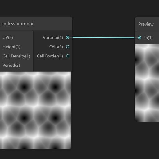
Seamless voronoi custom node for the Unity's shader graph.
Thanks all!
This did the trick. Outputing to Normal in PBR master rather than Vector Normal. I do have to invert specular UV. Not sure if there's a cleaner way to flip UV over Y axis than my gross split/multiply/subtract/etc
Is it possible to make a line wiggle like lightning with shaders? if so could anyone point me to some documentation or something on the subject? 😄
Any good tutorial on a metaball shader? The best one I found seems to assume I know a lot of stuff already 😂 Preferably one that doesn't just attempt to manipulate pixels, since I don't think you can get nice shading with that.
@elfin ivy something like distorting UVs?
more like something that generates an amount of vertices based on the length of the line and then moves them to the right or left
anyone made custom nodes? Based on some forum posts and videos I've been watching - this error is more recent.
'CodeFunctionNode' is inaccessible due to its protection level [Assembly-CSharp]csharp(CS0122)
CodeFunctionNode was an old C# API for custom nodes. The newer method is just to use the Custom Function node within shader graph (and can put that into a sub-graph if you want it to have a better name, easier to reuse, etc).
ah okay - I'm trying to get that seamless voronoi custom node to work, I just posted it a bit ago
Ah right, probably will need updating to use the custom function node instead
I think so? I'm not too familiar with the CodeFunctionNode tbh
yeah this is bizarre
I guess the first step is to change the file extension to hlsl and see what happens
Might just need to throw that code into a .hlsl file then set up a custom function node using that as the source. Depends if it's got the actual function part, like :
void FunctionName_float(float3 exampleInput, out float exampleOutput){

}
The docs I linked above goes through it. Should likely also use the #ifndef stuff so the file is only included once if you use the custom function multiple times too
yeah the way this old C# API is structured is very odd. I'll just have to make my way through it slowly
thanks for the link
Hello,
is there a way to have sprites cast shadows onto 3D objects in the Universal Render Pipeline?
And is it possible to do within shader graph?
I'm getting this error after using URP and creating a shader using ShaderGraphs. It doesn't seem to affect my game in any way as the shader I made is working fine but how do I get rid of the errors from popping up? I've looked up solutions on the web but can only find a few and they're all outdated.
is there any requirements for the 3d models that will pass through cel-shading?
so they won't look weird or anything
and is bevel needed?
Hi everyone i have a game for webGL, my materials glitter in Unity but not in the exported WebGl version... any idea ? Thanks a lot!
like this
Hey guys,
How I can make red, blue and green parts black and black part into white ?
In shadergraph
Is it correct ?
The Flip nodes there aren't doing anything, you can remove those. Basically what you have works, though I'd also Saturate after adding the channels together (to clamp between 0 and 1), could also use a One Minus node instead of Invert Colors, they do the same thing though.
Could also use a Maximum node instead of Add, which might be better if the red/green/blue parts can overlap.
@jolly adder
Takes the maximum value between the two inputs
Still I have a problem, my material is totally black. Do you know the reason ?
Not sure, the previews look okay so I'd assume it shouldn't be black. Make sure you save the graph (with the Save Asset button in top left). Maybe check the colour properties on the material
Yup, I did. It is weird. My color looks right.
Could you check it out ?
Is it okay when RGB is changed into vector1 ?
@regal stag Sorry for pinging
Hey! I'm trying to project a noise in view space, but I don't want it to move along with the position of the camera/screen. I want it to be tied to the world position, but still facing the camera. How do I do this in Shader Graph?
Is it correct ?
@jolly adder u r looking for swizzle node
@signal rapids use a position node set to world or absolute world, feed it to a split node, then feed the x and z to a vector 2 node. this you can feed in as the UV to the noise... I think that should do it
ah but still facing camera, that may require a little extra
@thick fulcrum Thanks, I'll fiddle with that setup for now!
question about stencil masks and ui. Can you use a stencil mask to cut out of a raw image or something similar. At the moment i have this where the object is being cut out of it in the scene view but nothing in the camera view. is there a way to get this working or should i look elsewhere
please @midnight minnow if you have an anwer
@jolly adder Sorry had to go afk. I took a brief look at it, seems it's something with the Albedo but not sure what exactly. It's hard to debug since I'm not really familiar with what the shader is meant to do. Saturating (Saturate node, clamps between 0 and 1) stops it going black but don't know if it's the intended result. Might be some negative values in the calculation causing that but can't really see where that would come from. The divide by "Zero Colour" property also seems a bit odd to me so could be something to do with that, especially if the colour has components that are zero as that would cause division by zero.
@signal rapids Maybe Position set to View but subtract the Camera position (from Camera node)
@regal stag Thanks. I think the problem was zero color although its value was not 0. I made it exposed and it is fixed.
performance question:
Should we have combine simple objects like crates, boxes and barrels in modeling softwares or let static batching does?
Suppose they are static.
Please answer when they are close to each other in a scene or not. thanks
and doesn't sprite atlas Unity work in the editor? I can not see the atlas in the frame debugger. UI elements are rendered individually.
and doesn't sprite atlas Unity work in the editor? I can not see the atlas in the frame debugger. UI elements are rendered individually.
It does, but there is a setting to enable it. When its on Unity has to rebake the atlas every time you press play, to avoid that overhead in-editor its turned off by default.
Its in the Project Settings > Editor:
https://docs.unity3d.com/Manual/class-EditorManager.html
Use Always Enabled if you want it on in the Editor
Note that i personally had issues with Sprite.packed in the past, it was unreliable when switching these settings on and off. Might have been fixed already though
Should we have combine simple objects like crates, boxes and barrels in modeling softwares or let static batching does?
That is very hard to answer, and doesnt have a single answer for every project and scenario. My guess would be that static batching is better, but its best not to trust a random guess and profile it.
Would it be possible to make two setups and test those side by side, in a release build?
@toxic flume hope that helps!
Hi guys! 🙂 I'm currently trying to learn to make nice fire vfx and started looking at the unity examples. They use this kind of shader and I was wondering, if I could get the same result using shader graph so I can get the same look in URP and HDRP. Does somebody know how I could achieve this?
@toxic flume Batching is only going to work when they have the same material. So if your crates and barrels have the same mat on them, they can batch. But they can instance too.
The problem with combining models at design time is that it isn't dynamic based on view frustum. So when people combine a bunch of things and they say "oh wow, 1 draw call!" yeah, it's one draw call but 85% of the giant-combined-model isn't even on the screen. But the CPU side has to submit the entire model to the gpu, which then clips out all the unnecessary stuff during clip-space culling. Frustum culling on the CPU side is basically nullified if even one pixel of the model is going to be visible.
So, close together? Hell yes if you want to and they share a material. Or let them static-batch. Hell no if they're spread out. IMO. I'd benchmark all of them against GPU instancing.
Then there's shader issues in some cases because with any batching, edit time or dynamic runtime, you don't have each object's origin anymore, it's all merged into one big mesh. Which might be OK, 99% of the time, but other times you want to know some individual object data in a shader.
2-cents.
Note that i personally had issues with
Sprite.packedin the past, it was unreliable when switching these settings on and off. Might have been fixed already though
@whole citrus Thanks, yes testing but it is hard to test everything. I have a massive terrain and several places, warehouse, store, industrial shed and workshop. I can say to 3D modelers and artists to combine all objects inside the workshop for example and also the workshop itself and give me a mesh with one material or separate objects like crates, boxes, walls, structural steel skeleton, steel bars, etc and only combine objects close to each other or composite elements.
@toxic flume In that case you do probably want different objects, only because that way with LOD you can turn specific ones off at a distance. I dont think thats possible with a single object
Agree. Also we can use simple colliders for them instead of one complex mesh collider.
My concern is to reduce vertices and triangles. It is high 500k for android devices.
Also I have to care about drawcalls. A trade off between them.
If an object is big, it will be rendered almost all the time but less drawcall.
Maybe, it is suitable to combine small objects close to each other and same types and instead split big terrain to smaller sections
@meager pelican Thank you, completely true. I have said to 3d artists to separate them. It is a big mesh with 75000 triangles and one material (only for one workshop), also one mesh collider!! It is sh...
Finally draw call and triangle/vertex count are both important and need a balance between them.
Question:
Pic in the left is what it is supposed to look like, it looks like that before I baked the scene (Pic on the right is with baked walls and floor). Why is it so flat and lacking shadows? This happens whenever I bake the lights.
Because you're sharing the same vertices for multiple faces
The normals of a mesh are stored with the vertices and a vertex can only store one normal
When a vertex is shared to make 3 faces all with different normals, the best it can do is make a normal that is between all 3 normals
@high hemlock Why do you have to make a new cube mesh for every block you spawn? Why can't you reuse the same mesh?
@low lichen I fixed the mesh being recreated. yeah, didn't notice that. I tried to give every face its own set of vertices now but I'm still seeing no change.
hey guys, would it be possible (or advisable) to follow a blender tutorial on a shader and transfer it to unitys shader graph? I know there cant be a 1:1 transition but the concepts should be the same right?
@pine night as I've not done blender shaders I'm going to out on a limb and say probably not. You can use tutorials / examples from shader forge and dare I mention UE4 to a certain extent I think probably better than Blender tutorials.
so, I feel like I'm overcomplicating something. I have a texture and a colour, and I want the colour to tint the texture, using the colour's alpha for well.. how strong it shoudl tint. 0 = no tint, 1 = image is completely that colour
float4 texCol = tex2D(_MainTex, i.uv); // Colour from texture
float4 adjCol = float4(texCol.r * (1 - _Color.a), texCol.g * (1 - _Color.a), texCol.b * (1 - _Color.a), texCol.a); // Only use part of the texture colour so the it doesn't all add together a lot, making it much brighter if the tint is added
float4 tintCol = float4(_Color.r * _Color.a, _Color.g * _Color.a, _Color.b * _Color.a, 0); // Only add part of the tint as defined by its alpha
float4 col = adjCol + tintCol;
Thats what I have now 🤔 Like, surely theres a better way to do that. Especially that part where I have ot separate the alpha out manually
Hey all, my last 2 replies here: https://forum.unity.com/threads/how-to-integrate-360-video-with-unity.485405/page-3#post-6529538
Has anyone had any experience getting stereo 360 images to project spherically without strangeness at the poles?

Unity Forum
Hi touloused,
thanks for the heads up on how to integrate video in a unity project and it's very cool; I have it working for android and was wondering...
@vague pike If it works, it works. But I think you are essentially doing a lerp. Perhaps something like :
float4 texCol = tex2D(_MainTex, i.uv);
float4 col = lerp(texCol, texCol * float4(_Color.rgb, 1), _Color.aaaa);
Just seemed very complicated haha. But yeah, basically a lerp I suppose. And nice, didn't know you can do _Color.rgb
Yeah, you can convert any float4 down to a vector with less components using r,g,b,a or x,y,z,w. They can also be in any order to switch the components around.
Is it possible to have an input like we have with Polygon colliders or input a 2D curve? I want to bend my image by the "curve"
so if I have a straight line as an image, I want to bend it like a "u" shape in the middle, I want to be able to input a polygon (like a 2D collider) or some way to input this shape
I can't hardcode the shape because there's lots of different bends I want to do
the only other solution, is to provide 2 points as input, and bend between those two points
with an amplitude float
but it doens't give as much flexibility
@high hemlock While you've added more vertices to the vertices array, the triangles array is still using the old ones as it only contains values from 0 to 7. So basically it's ignoring those new vertices entirely. There's now 0 to 23 vertex indices. The triangle array should use those indices to tell which vertex it should be using.
@vague pike @regal stag Sounds more like you want an alpha blend. (Sorry to butt in, Cyan, but it got me thinking about what it really is that they're asking about.) So 1-tint.a * the texCol, plus the texCol * texcol.a
So like if it was an overlay with transparency tinting from 0 (none) to 1 (full tint color).
Hmm might be, will have to try both haha. Can't really visualize that stuff yet
Yeah, I was just reading, and then I got to thinking about your question, and then the math. Not trying to be contradictory or anything. Maybe you really like the other way better. IDK.
Not sure as said 😂
It's fine to butt in, am still learning after all 😄
For some reason my quad seems to be kinda transparent anyway
(as in, even with just having a fragment shader that doesn't do anything in particular)
@meager pelican Ah right, "1 = image is completely that colour". I'm sure it said "image is tinted with colour" when I read that... might have been edited, or I'm just tired. Your example doesn't include the rgb of the tint _Color though, I assume one of those texCol is meant to be _Color.rgb right?
Does "RenderType"="Transparent" do that? 🤔
@rugged verge I assume you know about the https://docs.unity3d.com/ScriptReference/AnimationCurve.html
So you can evaluate the curve, and then pass that result to the shader by a variety of means.
@regal stag yes, pseudocode.
I should write it out I suppose, was in descriptive mode. 😉
like, can see the lines, and the cube behind it is visible through it too if you look closely
Is there a way to avoid declaring this array? colorBuffer is a Compute Buffer and mesh is a Mesh
Color[] newColors = new Color[newVerts.Length];
colorBuffer.GetData(newColors);
mesh.colors = newColors;
@fair sleet Don't think so, but you only have to make it once, then hold onto the reference.
v2f vert (appdata v)
{
  v2f o;
  o.vertex = UnityObjectToClipPos(v.vertex);
  o.uv = v.uv;
  return o;
}

float4 frag(v2f i) : SV_Target
{
    float4 texCol = tex2D(_MainTex, i.uv);
    float4 col = texCol;
    return col;
}
Like, nothing there should make it transparent?
@vague pike Transparency is usually achieved with "Queue"="Transparent" to move it into the transparent queue, and then uses a blend mode : https://docs.unity3d.com/Manual/SL-Blend.html.
e.g. Blend SrcAlpha OneMinusSrcAlpha is the normal transparency / alpha blending, similar to what Carpe was talking about above. If it's got any of those that might cause it to appear transparent.
Yeah, plus your input texture could have transparent alpha in it.
You can return float4(col.rgb, 1), but IDK why you're using a transparent queue then.
Hm right, had the Blend and Transparent queue, because apparently thats needed to get it to render properly if you have transparent parts on the images you're using
Yeah, if you're blending a background or something. Which I didn't understand from your other posts. 🙂
Shouldn't it still be like, not transparent though
Since theres no transparency on the tex used
That code doesn't tell you what the value of the .a component is.
Could be .9
for example.
What does your input texture have for alpha?
Made a new texture in paint.net thats literally just black and it's still transparent 😅
Yep, I could get the AnimationCurve in C#, but how do I pass it to the shader? Because I need the whole curve in a "single frame". It won't work for my use-case
The shader can't receive the curve, only float4, float, etc
In a texture. Like you do for gradients (Thanks Carpe! How do you do gradients! You dork!)
Second...typing, afk for a bit.
@vague pike What's the Blend mode in the shader?
Blend SrcAlpha OneMinusSrcAlpha
I need to bend my image according to the shape of the curve (both axis of the curve are: x, y), there's no time axis
oh
I'll take a look on textures
that might work
@vague pike I think it has to be the texture then, assuming the shader is still outputting the full float4 from the texture sample.
When I use textmeshpro UI with outline material, I see two drawcalls for each text instead of one, why?
Can I reduce it? and it is more performant to use only one material for texts inside a canvas, right? what about presets? in terms of drawcalls, I mean
Yeah, you call .evaluate in C# on the curve and make a texture with the offsets in it.
So create a texture that's like 1 x 1024. And then in C# do a for loop and evaluate the curve in 1024 steps, or whatever resolution you want. 2048. Or maybe just 512 or 256. Whatever.
Pass that to the shader. Then do a lookup at your UV.x offset (in the example you gave). So lookup the texture result at UV.x of the source texture = uvx of the lookup texture since they BOTH range from 0 to 1 in uv-speak (It's a % of the dimension) regardless of resolution.
@rugged verge
Sounds good, thanks for this useful info! I'll take a look at the docs and try it out
https://hastebin.com/ahohofivig.cs Maybe I'm missing something obvious 😅
Oh wait
I broke it anyway
Ah no
it's fine
But still the transparency issue
That's the tint, right? What about the TEXTURE?
Shader code looks fine to me
Is it maybe a setting in the texture import inspector that's messing with it? Like alpha source being from greyscale?
I guess scene view is just weird 😅
🙂 What's in _MainText?
It's not a single color like that color picker, it's a texture.
Though earlier it had the weird transparency in Game too
@meager pelican Guess you're right, that one normal map texture I tested with had an alpha component. The new black texture I made is just pure black 512x512 px. Which still looks weird in scene view but normal in game view somehow
If you ever want to know a single value in a shader, and if it ranges from 0 to 1 or you can scale it to that, you can output it as a color for debugging.
So change the last line to return float4(_mainTex.aaa, 1); and you'll get the alpha value output as a color.
In that case, grayscale.
Yeah, makes sense
By "looks weird in scene view" are you referring to just the grid being seen through the object now? That's kinda expected when working with transparency. Other objects shouldn't show through though, unless they are being sorted incorrectly based on render queue changes, or the origin of further object being closer to camera.
Change the last line to the above example, and let's check the alpha value.
Maybe just because it cuts off the lines, no clue
I think that's just the grid not being drawn there because it's based on depth, and the cube is still writing depth.
Hmm could be haha, the area does look darker, but that may just be a visual thing
It's still fully black so it's working fine
If it was actually transparent it would be kinda grey due to the blending
Well then what Cyan just said. Your alpha is one. (You can use the color picker to pick that color on something, and then make sure it's a 1 and not .974848 if you wish).
Oddly it's FEFEFE for both the cube and the plane haha, so not sure that completely works?
It's not 1!!! Otherwise it would be FFFFFF!
It's the input texture.
Color = black. Transparency is an additional variable.
Yes, black with full alpha
The 4th dimension! (Spooky music here)
As seen in that colour picker
I assume by FEFEFE they are only referring to the RGB part
Yeh, alpha was output as float4(_mainTex.aaa, 1);
And so alpha is FE (assuming it wasn't messed with otherwise).
No clue 😅
Right, I see
It might just be some post processing or something over the final image though if it's picked from a screenshot
The issue with not being able to just output actual values
Yeah, might. You could experiment and put col.a = 1; somewhere before returning, or return float4(_mainTex.rgb, 1); and see if it is any different.
gives 000000 for that latter one, if i just float4(1,1,1,1) i also get FEFEFE. So must be some rendering thing, not sure what thouhg
Fog is off at least, and no post processing volumes
OK, 0's are expected, that's the black. But does it LOOK any different than before?
Interesting about the FEFEFE. Mobile?
Screen brightness settings of some kind on GPU settings?
Mobile?
In paint.net it's FFFFFF when I make a pure white colour at least
And no, still seeing the grid lines (and apparent cube see-through, but thats just from the grid lines being gone there I think)
Well game view looks fine currently
I think you can hide the grid lines in the scene view, if they are annoying you that it's see-through
It's just confusing I guess, because I wouldn't expect it to be
Probably one of the settings at the top of the window
Sorting anything with transparent stuff gets difficult because a transparent shader typically doesn't write to the depth buffer (ZWrite On in the shader). I would assume that's why the grid shows through.
Wouldn't the grid be drawn first though? Because the cube goes over it, not behind it
Maybe I just need to read more of that shader/gpu book
So the game view is fine? What's your vert() function look like now?
I think the grid is being drawn last, based on the depth buffer to ensure it doesn't draw over objects
It's fairly common to do that in rendering as you don't want to bother rendering a pixel just to have it covered up later. Objects closer to the camera get drawn first when dealing with opaques, then ztest against the depth buffer. That way each pixel only needs to render once really.
I mean I tried a few things 😂 Like just float4(1, 1 ,1, 1) or float4(_Color.rgb, 1) etc, didn't seem to matter much for the see-through grid (in scene view, that is) or FEFEFE value (which is even FDFDFD in Game view).
Screw the scene view.
haha
Let's get the gave view to do what you want it to do.
I mean, it does, I think?
The game view is the "real" result.
//float4 col = lerp(texCol, float4(_Color.rgb, texCol.a), _Color.aaaa); // lerp
float4 col = (1 - _Color.a) * texCol + float4(_Color.rgb, texCol.a) * _Color.a; // yours
You'll need to add .rgb and return alpha 1. Sec
Lerp(A,B,T) is equal to A*(1-T) + B*T, so those are the same.
Nice, recreated lerp without trying to
return float4(col, 1);```
I think.That sorta seem to still do the same as lerp, but without working transparency
You said you wanted transparency to control the fade. But if you want the texture transparency to come through, use the _mainTex.a instead of the final 1.
And the lerp returned some different values (I think) than this does.
What you output for transparency is up to you. Not sure what you want.
Ah, yeah, that makes it work with transparency
Can't say I'm really seeing a difference though, will have to try around
It might be. I was going off of Cyan's origianal lerp which was
float4 col = lerp(texCol, texCol * float4(_Color.rgb, 1), _Color.aaaa);```
Which for the 2nd term is different, but might be equivalentI don't care which way you do it.
Just commenting.
I'm trying to apply my texture to my shader but unfortunately a UI image isn't a Renderer. Any idea how to get a property block and set it? Because I would have multiple instances of this (not one per material).
    Texture2D CreateTexture() {
        Texture2D texture = new Texture2D(TEXTURE_WIDTH, 1, TextureFormat.Alpha8, false);

        for (int x = 0; x < TEXTURE_WIDTH; x++) {
            texture.SetPixel(x, 0, new Color(0, 0, 0, x < 512 ? 0.4f : 0));
        }

        return texture;
    }

    void Awake() {
        _propBlock = new MaterialPropertyBlock();
        _renderer = GetComponent<Renderer>(); // Error here, because UI image isn't a Renderer
        UpdateBend();
    }

    void UpdateBend() {
        Texture tex = CreateTexture();

        // Get the current value of the material properties in the renderer.
        _renderer.GetPropertyBlock(_propBlock);
        // Assign our new value.
        _propBlock.SetTexture("_CurveTex", tex);
        // Apply the edited values to the renderer.
        _renderer.SetPropertyBlock(_propBlock);
    }
nvm found a workaround in https://answers.unity.com/questions/1163399/setpropertyblock-for-canvasrenderer.html
Unity is the ultimate game development platform. Use Unity to build high-quality 3D and 2D games, deploy them across mobile, desktop, VR/AR, consoles or the Web, and connect with loyal and enthusiastic players and customers.
Thanks for the great pointers Carpe, I finally implemented it and it works.
I see a lot of effects using cameras that only render some stuff.
How much of that can you do though? I'd imagine those textures eat extra memory and performance.
Yeah, there's overhead.
It's all an additional camera's worth of passes. It's "Stacked on top", but the engine has to sort object layers anyway, it's not all that bad depending on what you do. Sometimes it's the only way to do certain things, that you need to isolate to another camera that could even have a completely different view of the world.
You can do...IDK...lots. :p But you don't want to normally.
Just seems like for half the things I want to do or see the answer is "Use an extra camera that only render some stuff" haha
Well, maybe you can combine stuff. Sounds like you're being creative. 🙂
Metaballs? Extra camera!
Underwater depth effect that works when you can see above and below the water (i.e. camera is on the waterline)? Extra cameras!
etc
Yeah. I'm not 100% sure that's the only way, but if it works for ya, it works. That's fine. Water is always "fun".
Reflection, refraction, above, below, depth, waves....
I'm not really sure of any ways, just was a suggestion from someone when I asked about it
Yeah, still have to fix that refraction thing from Clay I have
It's one for the research time. Lots of it, depending on what you want to pull off. Take the time to do the research.
Yeah, currently I'm only barely shader-capable, so I've pushed that to later while I do more tutorials and randomly tinker around haha
Yeah. I copped out and purchased one a few years ago. Let them maintain it. lol.
I did that for sky/clouds too. Was on sale.
lol
Haha
It's fun until it takes a month, then it's not cost effective except for learning.
Sometimes for the harder stuff, let someone specialize.
Fair, does it to refraction well? :p i.e. doesn't refract objects in front of the water, doesn't give cut-off refraction on the edge of objects in the water, etc
Sadly it doesn't seem like theres a way to make completely accurate refraction without raytracing
For water, I've not even exhausted my options. Frankly I only had relative simple needs.
Way back when, I purchased AQUIAS water, and later on WeatherMaker for environment, which also has water and fog, and volumetrics.
There's other assets too, check the store. But it's fun to write and learn too. Some of this stuff gets pretty intense though.
Raytracing is basically what you have to do, yeah. Light rays are what refracts. But optimizations are possible I guess, that's where someone that specializes in an asset can spend their (months, years) of time optimizing and selling it to the world.
I just want refraction that doesn't have odd issues I guess haha
Like one tutorial had this issue, the purple crystal is in front of the water, but the edge gets refracted as if it were in the water (I upped the effect strength there to see it better, but you can see it otherwise too, just more subtle)
Huh, groovy. 😉
Then I followed a tutorial from Clay to fix that, which works well, but leaves me with the issue that now the refraction can be like "cut off" on the front of the objects in question, like here with the bottom of the crystal, esp. on the left.
At least I have some pointers on how to fix that though
Yeah, IDK. You should be able to recreate the pixel's position properly with the depth buffer, and project a ray and see what it hits you'd think without errors/artifacts. But I haven't tried it.
The thing is, some data isn't "there".
Yeah, without raytracing you have blind spots
Like whatever is in back of that purple crystal, isn't even drawn.
Even with, you can't get anything to go around stuff at all.
You can't?
Because it will never be drawn "behind" the purple thing.
Isn't that half the point of rays? 😄
Not unless you multipass.
No, but I'm not expert. The ray goes from the camera (your eye) into the scene, gets reflected or refracted depending on what you're doing. But the screen buffer only has the "top" pixel for the opaque pass.
I seemed to think thats how pathtraced reflection work at least. shoot ray from camera. Ray hits something and flies (reflected) off somewhere else to fetch the actual colour where it then hits
So you have no idea what is behind that purple blob. Could be some orange box, let's say, Completely obscured.
Hm, well I thought it fetches the colour for the ray/pixel directly from whatever is hit then
Rather than using a rendered buffer or so
But no clue
Yes, but not for what is logically behind it, but was never drawn. 😉
Because if it had to be drawn already, you coudl just warp screen positions?
That would be another pass I'd suppose if I understand you.
Maybe, not too firm on passes
I mean, you can do just about anything, but not in 1/30th of a second.
Say you have like a wall, with a bit on the right open
And a mirror there, it would have to to reflect the things behind the wall
even though those aren't drawn because blocked by the wall
Even RTX can't really do its raytracing, thats why it denoises with AI
Yeah, that's the rub. And there's API's for dealing with it somehow. I think the RTX stuff out now, and other vendor's stuff, manages some magic with that. But it isn't free. 😉
I just don't see the point of raytracing if you can't easily do that I guess
Becasue as said, if it had to be already drawn, I can just manipulate the pixels of what has been drawn, don't need raytracing for that
OK, there's different levels of "raytracing". What I'm talking about is raytracing into the scene using the existing buffers.
There's OTHER ray tracing methods that are doing something more....large....
I see
So for example you can do that "math raytracing" that describes everything as some math functions. With that you know the whole scene, soup to nuts.
And I suppose you can do ray tracing with some sort of special rendering from multiple perspectives.
But when we're dealing with water and "the scene" we often use the existing buffers that we already have.
I would've imagined it as like, shoot a ray from camera to pixel position. If it hits a reflective or refractive material, adjust ray direction as set and set the colour of the pixel already. Have a max travel distance, once thats up, it just keeps the last colour it has. If it hits something completely non-reflective or opaque, it just gets the colour of the pixels by calling the fragment shader for the given UVs where it hit the object
The only data you have at that point, without special techniques, is the red, green, blue of the pixel. Not material/PBR information unless your special techniques saved that away in another buffer. ;)
So it all depends, but I'm over my head now. I should dig into how they do all that, frankly, but I haven't.
Oh, and the depth. And then here's shadow maps.
Doesn't the fragment shader do PBR info?
I mean, raytracing would be sort of in the same stage that fragment sahders are run
But the point is that reflections, for example, come from cube maps from reflection probes, and are added to the pixel result as it is being rendered.
I thought thats for non-raytraced reflections
Guess I have to look into that stuff more anyway haha
Right. But there's screenspace reflections. And I don't remember how it is rendered and how they keep track of reflectivity. BUT...my original point remains, it is screenspace. So you don't know the pixel behind the pixel.
I guess I still don't see the point if you can't do that
As said, then I can just use screen position UV stuff to remap pixels
Don't need rays
Well, you have to do SOMETHING, the big debate is what and how.
I guess so haha
And I'm no expert, but I can guarantee you'll have a lot of fun in your research of the VARIOUS techniques.
Here's an excerpt from unity's older manual:
Screen Space Reflection is calculated by ray-marching from reflection points on the depth map to other surfaces. A reflection vector is calculated for each reflective point in the depth buffer. This vector is marched in steps until an intersection is found with another point on the depth buffer. This second point is then draw to the original point as a reflection.
that from 5.6! But is conveys the idea.
So it apparently stores some kind of reflectivity information into the buffer(s) as it renders a material on an object.
And it is raymarched.
Yeah, but thats distinct from actual raytraced reflections I believe
Sure. But what type of raytracing are you doing? 😉 I'm not even sure all vendors do it the same way. And then there's the roll-your-own stuff. Raytracing is just a general term, specific implementations can vary, as I understand it.
Oh I see
SSR is the culprit whenever I see reflections behave weirdly at certain agnles
Few techniques are perfect, if you're trying for realtime at 30 or 60 fps.
Hollywood uses different methods (and render farms) where they can take minutes per frame.
Probably
They could render the scene from 20 angles, and probably do, and then collect all the data and do the reflections added on.
https://www.youtube.com/watch?v=oCXVG0Qw7Fo here at least at like 0:14 you can see how the reflection vanish for SSR when stuff isn't on the screen anymore
while at like 1:08 with RTX it doesn't seem to matter

Just a simple quick video to demonstrate the differences and limitations of SSR when compared to RTX in Battlefield 5.
Yeah, I know RTX does some off screen stuff. Like "around the bus, reflected on the car" type of stuff in their demos. But I'm frankly not sure what they're doing. But it isn't free, whatever it is. Those are real high-end cards. 😉
Sure
It also doesn't look particularily good before they process it 😂 If you've seen that?
Too noisy because not enough power to raytrace enough
Oh yeah. They do some kind of random scattered sample, then apply AI to clean it all up. Or something. It's some black magic stuff for sure.
Yeah
Just interesting how noisy it can be I guess
Now if Firefox will stop hanging for like 5 minutes whenever I do soemthing on YT
Very, and how well it's de-noised, considering. And they appear to be doing lower-res rending for, say, those tree tops that aren't in the frame, but are reflected.
lol
Have a good day/night Inari. 🙂
Good night
I believe this goes here. I'm struggling since 3D text has the issue of being constantly visible, and I don't know what to do to stop it from being visible behind objects.
uhm so
i imported something into my unity 2020 hdrp project
and now all the shading practically doesnt exist
and i cant find a way to reverse it
can someone please help?
i really dont want to redo EVERYTHING
@wary socket use a shader that writes to depth, and set it to cutout opaque blending?
Or use textmesh pro
Guessing that if I want to have a grass shader on blended terrain, that I'll need to make a custom terrain shader that incorporates it?
Are we able to "instanced draw" multiple geometry types in same draw call?
Can i have like an array of meshes
And i send this to gpu:
meshindex, transformMat
How can i simply do that?
Is it practical what i'm trying to do here?
I don't know if unity will optimize the different meshes drawn with same material.
Dumb question probably, but can I use shader graph to create a custom fog for urp? Like say a fog that shows contours. Or would I have to create a custom material for every object which each had to use a scene depth node?
I'm a newbie, but you can probably just use an image effect? Or a replacement shader
@vague pike Not as newbie as I apparently. 🙂 Thank you, I'll try to google that!
Just watched a video about replacement shaders yesterday xD So thats why I'm thinking of it I guesss
Just saying, no clue if thats good advice
But I think you could probably just use image effect stuff to detect contour on the depth of the scene
(replacement shaders if you would want to use those https://www.youtube.com/watch?v=Tjl8jP5Nuvc)
@smoky bridge In theory, Unity should be able to optimize different meshes drawn with the same material and that is exactly what the SRP Batcher does
But I don't think there's any way to get the built-in render pipeline to do it
Except with static batching
Then again, can you do image/replacement shaders in graph?
@low lichen, thanks for info
I did some more research, from what i understand, i just need to use the same material for all my DrawMeshInstaced calls
And unity will do less draw calls then my DrawMeshInstanced calls
And i should be doing texture atlas stuff to have one big texture in this material
@low lichen Image effect too
Also googling anything about "vfx shader graph" is impossible since it only finds stuff about vfx graph thing 😂
Try putting "shader graph" in quotes
The VFX Shader Graph is related to VFX graph, it's used in the particle output blocks
I think replacement shaders don't work in URP (at least that's what I've gathered from others, I haven't actually tested it myself). Not sure about HDRP, probably not though.
There's an "overrideMaterial" option instead on the RenderObjects feature on the URP Forward Renderer. It's similar, but overrides the entire material not just the shader, so properties don't carry over.
You can also use a Blit Forward Renderer feature to apply a shader graph as an image effect. (e.g. https://github.com/Cyanilux/URP_BlitRenderFeature)
you need to search shader graph effect, as VFX is the standard overall term for the VFX Graph, which is different.
Well I was looking specifically for what unity calls vfx shader graph
I don't know of anything that Unity calls "VFX Shader Graph"
You can make shaders in Shader Graph that are compatible with VFX Graph
Is that what you are talking about?
Yes, that's a specific type of shader in Shader Graph made to work with VFX Graph
I see
Anyone know why when I activate this effect it just turns the object completely invisible? top branch goes into Alpha of master node, bottom one goes into Emission.
do you know if there is a list somewhere of all the keywords you can use in shader graph? like "_RECEIVE_SHADOWS_OFF" etc
I've tried googling it with very little result.
@grand jolt does the object become visible again if you move it nearer to the camera?
nope its just always totally invisible
Anyone made anything particularly nice lately that they want to show off? Brighten up my afternoon 😄
Doom, I trust the alpha cutoff is something sensible?
do you get the effect you expect to see when using an opaque object and cutout? (without the blending, but just to confirm the pattern is as you think it is in the scene, eg taking into account world position and scale)
alpha threshold is 0.5, i'll check about the pattern
how to get main light in hdrp
How can I upgrade a shader that uses the Built-In Renderer to use the URP?
if it's a built in Unity shader, there is URP equivalent.
If it's from asset store, check with dev to see if they have made one
If it's one you have written, then you need to either alter the code or re-do in shader graph
all else fails, find an alternative to do the same which is urp compatible
The shader I need modified is the custom terrain shader that is used for MapMagic and Voxeland. The terrain will not render properly (it's just a blob of solid color) without this exact shader.
But I also want to use Shader Graph for other things, as well as the Visual Effects Graph... Both require URP
If someone would convert it for me, I would gladly compensate :3
I'm just starting out with shaders and have what is probably a simple bug. When using a material based on an HDRP lit graph the material appears to have its emission set extremely high in the scene editor but in the material preview, and even the game itself, it looks normal.
and this graph is just the default. Nothing but a Lit Master node with emission set to black.
I can sample a texture fine, so the graph is being used, it just has insane emission in the scene editor
welp, told the HDRP Wizard to "Populate/Reset" the default resources folder and that fixed it? I don't suppose anyone can point me at why that might be the case?
How can I write my custom spritemask like RectMask implemented by MaskableGraphic?
Do I have to write a custom clip shader?
@short plume No idea but I had a similar experience - decided to use URP instead for my stuff
Wacky
switched to URP, issue is gone. Welp 🤷
@teal breach Thanks for the suggestion, it highlights a wee problem I have.
The effect works fine, but in order to see it I need to drop the Alpha Threshold to 0.3, which thankfull so far doesnt seem to affect sprites, so I guess it's fine as it is currently
also, is there any reason it stops rendering after i zoom out with the camera a bit?
Your GPU
@grand jolt
Your GPU is prob not gud enough
u need a pretty decent gpu to see it in long zoom
0-0
u understand??
yes, I understand "your GPU is shit".
As it happens apparently your right, if I use a simple scanline noise it works fine, using a more complex one just results in it not rendering at longer distances.....great...
I got some latency setting the material
in update()
one happens before the other, visually
cause I use a shader to animate (and lerp between them, giving them the exact same method, called within the same Update() method in the same instance, but references to different materials)
and I can see that one is like one frame behind the other, is there a way to synchronise this better?
I use material.SetFloat("_Lerp", lerp value here)
Wasnt my GPU BTW, I just had the far clipping plane at 2000, increased it to 10000 and it works perfectly.
What's the benefit of Amplify Shader if URP has shader graph now?
@lofty cape amplify works for default renderer as well and has more features
Suppose we want to add some highlights when the player is close to weapons,crate boxes,etc.
Each weapon has special highlight color. Is it suitable to ues different materials for normal and highlight situation and switch between them?
or one complex shader? I mean I want less drawcalls.
@toxic flume This is a case where you're trading between CPU and GPU performance. By having it in one shader, you reduce draw calls, improving CPU performance, but increase the complexity of the shader, decreasing GPU performance.
What makes sense depends on what your bottleneck currently is.
@low lichen
Yes, it is really a tradeoff, so I have to test it. thanks
Two questions:
How can I normalize local position of a model between -1 and 1?
Do I have to send my bounding box size to that shader and then normalize it?
Can I avoid computing some calculations in a shader in some situations without condition?
I know I can use lerp and step but I have to compute values at first then step or lerp.
I've made a custom lit shader in shader graph, lighting is working however it does not seem to do environment reflections the same as unity standard. so when you have built in shader next to custom shader it's obvious there is a difference (to me at least).
I say it's related to environment reflections as when I toggle that setting in the unity shader, the effect goes away.
Question is, how does one recreate the effect in shader graph if it's possible?
looks almost like some sort of Fresnel lighting, but related to environment reflections. any helpful suggestions welcome
Assuming you're using URP, It's probably related to this GlossyEnvironmentReflection function : https://github.com/Unity-Technologies/Graphics/blob/4ad03e7975af24c8e60c974edb24c696e74e39b3/com.unity.render-pipelines.universal/ShaderLibrary/Lighting.hlsl#L467
Which is used in the GlobalIllumination function, which also includes a fresnel term, all passed into a EnvironmentBRDF function.
Basically a bunch of Ctrl+F to find stuff but might be able to find out how they calculate it from those
Are there any more YT channels that do "shader case studies" (i.e. looking at how you'd recreate an effect from some game)
Are you already aware of the Makin' Stuff Look Good ones? (https://www.youtube.com/c/DanMoranGameDev/videos)

YouTube
Welcome to Makin' Stuff Look Good in Video Games! This channel is all about techniques for getting the most out of your games. Particles, shaders, image effe...
Should probably ping when I reply, always forget about that. @thick fulcrum ^^ @vague pike ^
Thanks @regal stag will check into that, sounds like it from your description 👍
@regal stag Thats the one I mean haha, just wondered if anyone else does those
think I'm going mad, since the effect EnvironmentalReflections is shown in the material preview and can be toggled on/off with correct keyword. Seems must be something related to how I've done smoothness, but I'm sure it's just the alpha of my metalic texture * value 0-1 on a slider.
I've made another pbr graph with just color and smoothness, which works fine 🤷
must be something with my original graph
bah must be something with the model, the shader graph works fine elsewhere. Problem solved I guess 😆
hey I got this burst VFX ,how would I activate it in script?
@thick fulcrum it could possibly be the UVs on the model, not sure XD
How hard it would be making such a shader?? @regal stag maybe you could do some new tutorial with it ? 😄 XD
Thanks @devout quarry
@grand jolt thanks for suggestion, but it was badly placed reflection probe 🤣 runs away to hide in shame
Wouldn't mind that one myself, looks gorgeous
Hey guys
im asking here because i really don't know this stuff and you guys look like the perfect people to ask
So i was trying to make a snow map, and i imported some assets from Quixel
i assigned some objects with the materials and they somehow look way different
Can someone please explain in a few words why it's like this and what i should look out for?
your ambient lighting may be tinting the snow, try making your directional light cooler
@indigo frost
also make sure the albedo color is set to white
I'm trying to make a specular only plane for AR. I've tried doing it using the built in URP Lit sharers and It kind of works but the plane is not 100% transparent and there is still some color visible. Is it possible with the built in URP shaders or would I have to use a custom shader? (I have no prior shader coding experience so please point in me the right direction, I'm willing to learn 🙂 )
Hi Im trying to make hair for my character but after adding the material to hair, the color appears only in front of the head why is that happening ?
in Blender it looks normal
hey, i am not sure of where to post but i had this question.
is it possible to blend a screen texture with a screen space shadow buffer or something like that?
the thing is that i am trying to make DXR (ray traced) contact shadows in the built in render pipeline, and that steps work perfectly. The thing is that i dont know how to blend my shadows with the shadowmaps. Thanks in advance
nvm found a way
Quick question: can unlit shaders still be emissive?
nope
well they cant receive or interact with light
unless you made your own unlit shader and multiplied the albedo by a super high value
i guess you want it for bloom, right?
@wary horizon
Yea, just bloom
its for a camera position based world boundry indicator
@golden glade
ok
so yeah
make an unlit textured shader and try multiplying the color by a high value
idk tho
nvm
i just remembered Particle unlit shader has an emission imput
use that shader
lmao marki
well coming back to the topic
that is also easy to do specially on this shader
if you set it to Fade rendering mode
there is an option for camera fading
sorry
surface type
also i didnt know you were in urp
im not sure about the differences in options
Yea, probably not possible with URP
transparent
well if you are in URP it should be easier w/ shader graph
get the distance from the world position of the pixel to the camera position and modify alpha based on that
i just didnt want to use a lit shader if i didnt need to, just for emission for bloom
Lit is much more heavy than unlit, right?
shader graph had an unlit node right?
i mean if you are targeting PC the difference is not noticeable at all
or high end mobiles
im not sure tho
Emission isn't really anything special in URP as far as I'm aware - it's basically an unlit colour added to the lit result, assuming it's not a shader used for lightmapping at least. Bloom just relies on a bright colour, so outputting an unlit colour will work fine. If HDR is enabled, may need to multiply by a value or use a HDR colour with the Intensity set, would depend on the threshold set on the bloom volume.
Yea, no emission node :/
so multiplying the color by a value will act as the "intensity"
is that what you're saying
ye
Does that look right?
To be fair. i dont know what im doing
basically the material should be completely transparent. and when you get up close to it, it should fade in. For a world boundry indicator
and tiled across the whole model too
Aint working lmao
are you doing it in the right way? it might be inverse (fade when too close)
YEESS FINALLY I BLENDED THEM
thats weird
The Distance would return a larger value the further you walk away. I'd use a Smoothstep node after it, you can then use the first Edge input as the radius you need to be in for the effect to be fully visible, and the second input as a larger value for the falloff so it fades out. (It would also clamp for you so you don't need the clamp node)
hmm yeah do what cyan said
i have no idea what cyan just said
One Minus would also work yeah, smoothstep has a bit better control over the radius
Like that
im not sure about what cyan said so i could tell you if its ok if you use one minus lol
idk
Yeah, might need to switch the edge inputs around though
thats just what i would do
FLipping the edges makes the texture black
Ok, i must have it back - to - front somehow
i get closer, it fades out
Oh, maybe it was correct with the edge inputs the other way around then
ye
I also wouldn't use the alpha clip threshold here, just set that to 0
with flipping like cyan said, it looks better
But, it is black by default, and not completely transparent
are you using that as color or alpha
Multiply the smoothstep result with the alpha instead of the colour
just the screenshot i sent above
transparent surface mode in main node settings
when you hover this you should see a small settings button
Its black in the preview
Take the Smoothstep output and Multiply with the A of the texture output, before putting it into the Alpha on the master node
use your distance stuff in Alpha
Instead of multiplying by the colour part
Looks like i need that alpha clip
oh no, even with the alpha clip as it was, its still doing it
You shouldn't need the alpha clip if you are multiplying the texture alpha with the smoothstep
Ill try your method now cyan
Perfect @regal stag Now i need to see how i can tile the texture across the mesh
The Tiling And Offset node into the UV of the texture sample should help with that.
Assuming the texture is also set to Repeat wrap mode on import / in inspector
Hey has anyone else been getting errors on startup because Unity cannot load your editor layout?
I think this has something to do with me exiting the project with shader graph windows still open.
Then Unity attempting to load the editor layout I was using last and returning an error as whichever shader graph windows are not set in the editor layout.
The prompt gives you the following options
**- load the default layout
- revert to factory settings
- or quit the project**
Usually when I choose load the default layout the project quits/crashes - only to be working fine with the default layout set when I relaunch the project.
@solar sinew yea and it's not to do with shader graph, update to newer version "should" fix it as this was issue few versions back.
Okay nice. I did recently download the 2020.2 beta to test out the new shader graph without master nodes
although no official comments, it was after I played with beta that I had issues too ^^
you can sometimes get around it by copying the editor layout files from another project, depending on your version though this does not always get around the issue
Two questions:
How can I normalize local position of a model between -1 and 1?
Do I have to send my bounding box size to that shader and then normalize it?
Can I avoid computing some calculations in a shader in some situations without condition?
I know I can use lerp and step but I have to compute values at first then step or lerp.
@toxic flume probably best to send the bounding box size to the shader, unless all your models are uniform. for example the unity cube in shader object space is from 0 to 1, 0.5 being it's middle * scale.
conditionals are not as expensive as one may think, especially on modern hardware it's hardly noticeable. but testing would be only way to know for sure.
sometimes a custom node is needed to get around awkward situations that don't lend themselves easily to graph logic.

rofl