#archived-shaders
1 messages · Page 157 of 1
no problem glad to help
i can apply this to a circle "quad" too right?
ah ok nice
you can change it to use world space or object space if that more fitting for your usecase
aight thanks for the help alot ^^
need to do more reading into this stuff
gl on ur work ^^
The good thing is that you never stop learning about new cool stuff.
xD
@knotty juniper do you know a good way to animate the ripples so they are flowing out?
@swift fiber add Time to the distance value , for the speed you can multibly the time value before adding it
or you can expose a value that you can animate or change by scirpt if you need maunal controll
I am having an issue where I want to apply the shadow and AO of the baked lighting, but discard the GI information, is that possible?
How can i turn this green leaf completely to white ?
Does the texture have an alpha value?
Try getting the A output and see what that gives
Don't know if this is the right place to ask this. I'm looking for a few sims style shaders and just wondering if they exist (open or asset store).
- boolean mesh cut-out's (for windows in walls)
- invisible objects (for viewing rooms)
Howdy Unity friends! I'm working on this fire shader for my game, and I'm trying to get an outline of the image. Usually I just do this by performing a Step operation to get increase the scale of the art, then subtract A from B, which leaves me with an outline. HOWEVER - in the case of the shader I show here - the Step function in the area I have circled in red - no matter what I make the value, it doesn't change the pixels whatsoever. Only if I set it to 0 (all black) or 1 (all white) does it change at all. Can anyone notice something I'm doing wrong here to prevent me from being able to get the outline?
@remote osprey You can't really Step a value that's already been put through a step node. The step node relies on multiple values, like a gradient, and returns 0 or 1 based on whether it's smaller or larger than the edge value. After you've got a value of 0 or 1, a step with 0.26 isn't going to change anything, as 0 is smaller and 1 is larger - the only difference being your In and edge inputs are switched, so the black/white output is switched around.
You could also use UV->Split->G to achieve a similar gradient to avoid the texture samples.
AH... okay. That does make sense.
Thanks I'll have to try that! I was having some issues getting a procedural gradient to work right so I said SCREW IT and went texture lmao. I'd rather do it with code though.
hello!
So based on what I have here, can you think of a way that I could still achieve an outline? Or would I need to kill off the first Step node for that to happen?
Howdy hey
is there a way to use raymarching in shadergraph?
I tried used custom functions and 3d textures
I cant get the 3d textures to work
Im trying to make volumetric clouds using raymarching, but since I have not achieved that no matter what I try, I used stacked noises in a mesh, however it kills perfomance as long as you increase the stack size
this is my result using stacking
@remote osprey I think you want to do two steps and subtract them, similar to this :
Giving that direction a try, thank you @regal stag !
I've got some shaders built in Shader Graph using URP, and I'm getting pink shaders for some of them in the built executable, but they seem to work just fine in the editor. Is this a common thing with a simple workaround I should know about or is there something much bigger here I need to work on?
@atomic glade which plattform are you building to?
On Windows, building for Windows
Hmmm have you enabled the experimental shader preprocessor in the editor?
I'm not sure. Where could I check that?
in project settings - editor
@regal stag Worked perfectly. Thanks mate!!
I don't see anything that looks like experimental shader stuff
I would like to apply unity's lightmap in a different way. Is this done within the lighting function?
Got a bit to do on it still until it's finished but here's the current state - with that working outline.
How can i turn this green leaf completely to white ?
@coarse sage
With grey scale tones or not?
If not, multiply the apha x white color. You'll get a white mask. Or if there's no alpha, you can use the any node on the .RGB assuming the black is all 0 (exactly 0).
If you want the greyscale values, you'll either have to do some math, or just multiply white by the green color component. The math for luminescence is in UnityCG.cginc in their source, but basically they set a vector depending on what colorspace you're in
#define unity_ColorSpaceLuminance half4(0.22, 0.707, 0.071, 0.0) // Legacy: alpha is set to 0.0 to specify gamma mode
or
#define unity_ColorSpaceLuminance half4(0.0396819152, 0.458021790, 0.00609653955, 1.0) // Legacy: alpha is set to 1.0 to specify linear mode
and then they do
// Converts color to luminance (grayscale)
inline half Luminance(half3 rgb)
{
    return dot(rgb, unity_ColorSpaceLuminance.rgb);
}```I thought SG had a luminance node, but I didn't see it...
But it's just a dot-product node anyway, feeding in one of those two values and your color.
You can then swizzle it .xxx to get a greyscale/grayscale.
Come to think of it, you might be better off just converting it to "black and white" in a graphics program if you want grayscale, and then multiply it by green or whatever color to get a colorized leaf.
@silk wharf Using a custom function node, you should totally be able to do raymarching in a 3D texture. What was your issue there ?
Does anyone know how the values in _CameraDepthTexture are computed? I need to replicate the computation of the depth texture. All resources I can find only talk about how to use the depth texture for custom effects but not how it is actually computed.
idk im sorry drummerb
doers anybody know how bad for file size or build time it is to have unused shaders in a project?
unused shaders are stripped out when building. Might still loose some time to be filtered.
@safe tide What do you mean ? The depth texture is rendered from the objects.
@amber saffron I want to render the depth of a mesh into a render texture
An easy thing to do then is to write a quick unlit shader that outputs depth, and apply it to your object when rendering to the RT
@amber saffron
An easy thing to do then is to write a quick unlit shader that outputs depth
that's exactly what I'm trying to do 😄 but I'm having trouble figuring out what to output in the frag shader
there is an example in the docs, but it seems to be out dated, as the UNITY_OUTPUT_DEPTH macro it uses just resolves to return 0
@safe tide Is this for URP? HDRP? Built-in?
@low lichen built-in
@safe tide This is the shadowcaster pass that most Unity shaders fallback to
Pass
{
    Name "ShadowCaster"
    Tags { "LightMode" = "ShadowCaster" }

    ZWrite On ZTest LEqual Cull Off

    CGPROGRAM
    #pragma vertex vert
    #pragma fragment frag
    #pragma target 2.0
    #pragma multi_compile_shadowcaster
    #include "UnityCG.cginc"

    struct v2f {
        V2F_SHADOW_CASTER;
        UNITY_VERTEX_OUTPUT_STEREO
    };

    v2f vert( appdata_base v )
    {
        v2f o;
        UNITY_SETUP_INSTANCE_ID(v);
        UNITY_INITIALIZE_VERTEX_OUTPUT_STEREO(o);
        TRANSFER_SHADOW_CASTER_NORMALOFFSET(o)
        return o;
    }

    float4 frag( v2f i ) : SV_Target
    {
        SHADOW_CASTER_FRAGMENT(i)
    }
    ENDCG
}

GitHub
A comprehensive archive for Unity's built-in shaders code - cheeseburgames/unity-builtin_shaders
If that doesn't work, here's a shader I made a while ago that does this
https://hatebin.com/cgqpjjdkun
@low lichen thanks a lot for your example! I tried your version from hatebin (actually I had a very similar version also), but for some reason the output is just constant white
Well, it will only be completely black at the far plane
Which could be thousands of units away, depending on how the camera is setup
ah is this linear depth then?
The scene camera has a dynamic far plane unless you override it
Yeah, this is linear depth
doesn't the CameraDepthTexture have non-linear depth?
Hmm, yeah it does
Have you tried the example shader in this documentation?
https://docs.unity3d.com/Manual/SL-DepthTextures.html

Oh actually, it appears to be legacy and does nothing
yes, but the macro in the frag shader (UNITY_OUTPUT_DEPTH) seems to resolve to return 0
I think the depth is rendered implicitly somehow into a native depth texture
I'm not sure
Maybe just do the opposite of Linear01Depth before returning it in the shader?
@low lichen hmm, almost:
left is my shader, right is CameraDepthTexture,
ok, I guess this is an OpenGL vs DirectX difference, since with DX11 it looks identical:
You could look back at the history of UnityCG.cginc and see what those macros contained before they became legacy. This repo has a history all the way back to 3.4
https://github.com/cheeseburgames/unity-builtin_shaders/blob/4.5/Shaders/CGIncludes/UnityCG.cginc
oh wow, that's super helpful, thanks
I used a different repo, but that only went back to 2017
now it looks identical on OpenGL as well, I think
Does the left side look a little darker on the closest corner or is that just me?
hmm
They look the same to me
I think they are the same, when I enable the Frame Debugger and toggle back and forth between the depth texture and mine, I can't see a difference
I had to remove the 1-depth and added the inverse of the Linear01Depth function as you suggested:
fixed4 frag (v2f i) : SV_Target
{
    float depth = clamp(i.depth, 0.0, 1.0);
    depth = (1 / depth - _ZBufferParams.y) / _ZBufferParams.x;
    return fixed4(depth, 0, 0, 1);
}
thanks a lot for your help! @low lichen
Sure, no problem
Does anyone know anything about the integration of DXC? There was a pull request in a SRP repo but that repo is gone now
@young rampart it has just moved to https://github.com/Unity-Technologies/Graphics

GitHub
Unity Graphics - Including Scriptable Render Pipeline - Unity-Technologies/Graphics
the PR we merged here : https://github.com/Unity-Technologies/Graphics/pull/14
As for implementation of DXC in a certain unity version, I didn't personally follow it very closely, but I know it is/has being done.
GitHub
Purpose of this PR
NOTE: just redoing the PR Unity-Technologies/ScriptableRenderPipeline#6304 which didn't land before the transition to the new repo
To make SRP shaders compatible with th...
Hi I made this conveyor belt shader but I want to show it only on top. How can I achieve it
Simple method : make you own 3D model with 2 materials (top, and the rest). You can even use probuilder for that.
Complex method : filter by normal direction to only show it on the top face.
It's not a complex method for @midnight fiber
Already been using shader graph a bunch
haha I was making this shader for 4 hours :/
Im new to shaders and I dont even know what that means the complex method
id need some eassistance
So maybe splitting the mesh into two submeshes with different materials will be better ? 🙂
I tried the simple method but I have problem. The shader doesnt fit
this is the model from blender with two materials like you said
why is it so scaled?
You probably need to check the UVs
what does it mean? everybody keeps talking about UVs. I'm lost
UVs are coordinates for each vertex that are used to tell what part of the texture to use on the face. The current UVs probably are separated so that each face of the cube uses a different section of the whole texture, when you instead want the top face to use the entire texture.
I think if you just select the top face, hit U and "Reset" the uvs it'll do that. (I haven't used blender 2.8 so don't know if the keybinding has changed though)
oh thank you
Just map the side's uv's to some black part of the border texture. 1 material, 1 draw call. It looks like it has a black border on the texture.
There's a UV editor in blender.
I'm a bit shocked now
What's "chocked" mean?
Sorry, classic french mispell when writing english without paying attention
Ah. :)
Why shocked?
Writing shaders without knowing about UVs
Ah. 🙂
I thought I ticked you off or something. I didn't mean to be contrary to your post, only to help the guy.
Sorry if it felt like that. You guys helped him understand and fix his issues, and this is great. But I just couldn't imagin that it was possible to start making shader without knowing what UVs are.
Shadergraph makes it pretty easy to get into shaders without knowing some of the basics. If you're always working with quads or unity primitive meshes you don't necessarily have to know anything about modelling or uvs.
All those graphical tools make it to easy for people 😄
It's kinda similar to people trying to use the Fresnel Effect node to get outlines on flat quads/planes, because the preview of the node looks like a glowing outline around a sphere.
I made another part. Its half cylinder and when I apply the shader on it, the shader is sqeezed I tried lots of uv settings I just dont know how it should be
could somebody help me understand please
Do that same 4 step thing, and the big quad, and then another 4 step thing. On the mesh.
Then assign the UV's accordingly, to make from 0% TO 100% through the texture.
So all one mesh.
The first "box" might be from 0 to .1 in the Y uv. The next box from .1 to .2, then .2 to .3. then .3 to .6, then .6 to .7, .7 to .8 and then .9 to 1.0
Imagine the texture is the background of that grey box in blender. You've spread out the 4 strips across the whole texture
so make squares out if it?
Horizontally, that is what you want
Mentally unwrap the WHOLE belt. 4 boxes, big square, 4 more boxes (and also sides).
But you don't want it to stretch out the whole texture vertically
If it helps, you could actually assign a texture in blender to see what it'll look like
IDK if he's horizontal or vertical.
the shader goes from top to bottom
I think it was vertical
No, that's just one part. Do the WHOLE belt as one mesh.
Duplicate that, and put the other "box" in the middle. And merge them all.
but I dont know how to make one mesh out of the whole belt
There's only so much I can do for ya on a discord.
I know
Maybe someone else will walk you through blender, but barring that, you'll have to google some tutorials. I can tell you what you want (one way, anyway).
I'm trying to help you understand, conceptually.
maybe if you draw xd
Sec, I'll make you a graphic.
thank you
nothing fancy just a sketch will do
this is with the texture I just dont see whats wrong
OK, world's worst graphic coming up:
So that "box" on the bottom of the mesh might map to 0,0 in the lower left, to (1, .1) in its upper right corner. Etc.
As you scroll the texture, it will just "wrap around" the mesh. including the rounded ends.
but what is the big square in the middle
What you called "the top". The 3 boxes on the top are the front side, and the three on the bottom are the "back" side. The sides of the mesh are omitted, but you can map those to some black border on the texture. Like (0, 0.001) thru (.001, .002). Who cares? It's all black.
and what do you mean by front side and back side when its only half cylinder + it has only 4 sides not 6
I appreciate your help but you cant explain this to me I will work with what I have thank you sorry for your time
this is some hard thingie I just dont see it
OK 4 curves, I only drew 3.
Doesn't matter. Same concept.
curve, curve, curve, curve, long flat part, curve, curve, curve, curve. All one mesh.
So it looks like a scroll ish thing.
I know. Add it. And another curved part on the other side. ONE MESH.
so make cylinder?
Start with 1/2 cylinder like you just showed. Add a face on the top edge. Stretch it to be the "long top". Then add another 1/2 cylinder on the other side.
Add sides.
Then UV unwrap it, and fix it all up.
You might want to go close off the bottom too. For fun. No open mesh.
And look up "recalculate normals" too when you get a chance.
sec
OK, new world's record lousy drawing:
Maybe start with a box, then stretch it out to be a flat box, and then subdivide the ends.
round them off
lol yes but this edge is another part its not part of the middle piece
Make it part of it. ONE MESH.
🤦♂️
That's the easiest way, and fastest too. Otherwise you're going to run into problems syncing the meshes's uv mappings as you animate this.
Yes.
I did it like this tho
Sure. Is that UV mapping window?
yes
Or the mesh?
You need four more of those "box things" on bottom.
why?
ohyeah it doesnt fit
from bottom
but how do I get them the "box things" I cant just dupe them in uv editor
The "boxes" are the MESH. In the MESH EDITOR. The verts and faces and stuff.
ok ill make it one mesh
I've heard that somewhere before.
I don't think they have two curved parts yet
But you'll likely want to curve the other end next and will have to do the same thing to get the uvs connecting properly.
how do I merge two vertices
nvm got it I recalled
why in such weird shapes
I have 2 squares and 6 rectangles and on the UV they show up as these "triangles"
@midnight fiber take 10 mins and watch this https://m.youtube.com/watch?v=SGXkFYS4f7I
Let's make a cool simple triplanar shader for isometric games using Unity Shader Graph.
This triplanar shader is very useful for 3D isometric games.It's also very optimized so that you can easily use it for your mobile games.
Download the project files : http://bit.ly/2KAEL...
I really think that would be easier for you
thanks
And if it isn't easier then you only lost 10 mins
well it doesnt help with the UVs but its useful and easy, I will use this for something else though
In Shadergraph, why does the UI prevent me from linking some specific output sometimes ?
How do I force it to accept any float3 source into Vertex position ?
You can't force some things
I think its blocks you when you want to mix vertex/fragment stuff
what are you trying to do?
like a sample texture node into vertex position?
Trying to make a basic PSX shader, and one of the step require a Posterize node. Even when re-converting it into object space afterward it refuse to accept the modified coordinates.
I think in some older versions of shadergraph I've had to take the inputs out of the fragment stages to connect something to the vertex stage, then reconnect them. But there are certain nodes that also just locked to a fragment only and can't be used in vertex inputs (like the Sample Texture node as Alexander mentioned - you have to use a Sample Texture LOD node instead).
Found the exact culprit, it's the "Scene Depth" a bit above in the calculation chain.
... what do I need to do then ?
Figure out a way to do the shader without the scene depth?
_<
How are you using it currently?
I'm just trying to copy a shadergraph tutorial someone else posted.
https://forum.unity.com/threads/closed-is-it-possible-to-create-ps1-vertex-snapping-shader-in-shader-graph.683860/
Unity Forum
In the past I used this shader: https://github.com/dsoft20/psx_retroshader/blob/master/Assets/Shaders/psx-unlit.shader
Unfortunately, It is not working...
Hello. I've just begun dipping my toes into Shader Graph. I love it. I created a vertex displacement effect for a character and everything is great, but I would like to use a 2dTexture to mask the vertex displacement off the hands and other areas that are getting too much influence. I've tried this setup and it won't plug into the vertex position slot. Please let me know if there is a better way to approach the problem, thank you!
Welcome to the club 😄
@polar relic Right but that thread isn't using the scene depth, they have a subgraph which they've also shared.
I'd probably use the view space position instead of world - camera though.. and just use .z instead of adding all the xyz components up.
@carmine iron You need to use a Sample Texture 2D LOD node instead
@regal stag Ok, thank you. I'll look into that!
Yeah I tried to use scene depth + vertex manipulation before but didn't work
which makes sense
Well that definitely allows me to make the connection in shader graph, and it mostly works how I expect, but now the verts in my 'masked' area seem to go to object space 0~, instead of just not being displaced. Close! Thanks though @regal stag
@carmine iron You are probably multiplying, so everything goes to 0 if the texture result is 0. Instead you'll want to only multiply the offset part, or take one of the R/G/B/A outputs into the T of a Lerp, have the A as the Position node (object space) for the regular position, and B as the offset position.
@regal stag Thanks, I'll look into that! It does make sense why the 'error' is occurring now
I guess I get it. I need to introduce my meshes regular vertex state into the shader too
@regal stag Just got it working. Exactly how I expect, thanks!

Further progress on that fire shader from yesterday.
In a very 'This Is Fine' setup.
Been having some trouble with a couple of my URP Shader Graph shaders. If anyone could tell me what I'm doing wrong, I'd appreciate it a lot! So in essence I made a simple rimlight shader which I used for a handful of custom Materials where I change the colors in the inspector. In the end I export the Shader, Materials and import them into a new URP project. When I check out the custom colored Materials, their colors and intensity levels are back to the defaults set in the Shader Graph. What am I doing wrong?
@grizzled prairie This might be due to the property References in the shadergraph blackboard not being changed from their default values. I think the generated ones can change, so you should set them to something more readable/useful.
e.g. Instead of Vector1_D23434D2 or whatever, set it to _FresnelSize.
I think what @grizzled prairie is saying is that they want the inspector-set values to remain
these values should be in the materials, but in case they were using instanced materials, they'd need to save it in a scene or a prefab or something to keep the values
I think they are just copying the materials into a different project and losing that inspector data because the references have changed
@lavish sierra Yeah, I'm saving multiple color variations which just went back to the light blue and blue color in the shader
@amber saffron I tried using raymarching with a custom function, however im not sure what I need to put inside the function, I used a for, for the steps thing, but idk what to do with the 3D texture in the function
@regal stag where is this data stored in the first place?
it seems unlikely that the references could change relative to the stored data, but maybe the .meta files got left behind or something
The inspector data is stored in the .mat file.
e.g. m_Floats:
- Vector1_67EBD77D: 0.2
But I don't think the shadergraph saves the Vector1_67EBD77D
I could try changing those values and exporting again
Oh or maybe it does, "m_DefaultReferenceName": "Vector1_67EBD77D"
I'm sure I've had it change when moving the file between projects too though.
Hmm maybe that happened on really old versions, either that or I'm going mad. I'm not sure why else they would reset to default values.
how could I make the texture not go into the lerp if a bool is off?
You'd usually use a Branch node with a boolean, which outputs a value based on whether the boolean is True or False.
@regal stag Welp. What do I do in the case of 2018.1 where I can't change the References 😄
That works surprisingly well, Thank you!
@grizzled prairie Oh wow. I guess there's not much you can do, you'll probably just have to recreate the materials.
Seems like they're read only in the inspector in that version
And yeah, I looked over some old shadergraph files and they don't include the m_DefaultReferenceName like newer ones do, so those references change. Good to know they won't change with newer versions though.

Could change them in debug mode, but I guess things could potentially mess up. I only have one source project to gamble with though, since I can't export them safely
I'd probably just recreate the materials, at least there's only 3 values per material.
Yeah, I might have to do that, though I wasn't looking forward to it 😄
Thanks for the help, I'll try to change the References and see if it sticks
@silk wharf The usual thing for doing clouds is to march through the volume, and sample the 3D texture that is a "density texture", to accumulate the cloud color at each step, depending on the density.
@amber saffron is there any documentation about acomulating the code from the 3D texture?
Results of some quick google search :
https://www.shadertoy.com/view/lss3zr
https://youtu.be/4QOcCGI6xOU
http://www.shadowmint.com/articles/code-volumetric-shader-1/


Clouds are lovely and fluffy and rather difficult to make.
In this video I attempt to create clouds from code in the Unity game engine.
Project source (Unity, HLSL, C#) is now out of early access:
https://github.com/SebLague/Clouds
If you'd like to support the creation of mor...
@amber saffron I already saw it, I converted most of his written code to shader graph, the only thing that I dont understand, is how can I accomulate the color from the volume
I used his sampleDensity function but didnt show any results in my shadergraph
It's all explained in the video. The color is the result of sampling multiple times in the volume, from the view direction and then toward the light. And if the maximum density is not met, you then redo the operation a bit further and add the result, etc etc
Clouds are lovely and fluffy and rather difficult to make.
In this video I attempt to create clouds from code in the Unity game engine.
Project source (Unity, HLSL, C#) is now out of early access:
https://github.com/SebLague/Clouds
If you'd like to support the creation of mor...
@silk wharf The source code for it is public :) https://github.com/SebLague/Clouds

GitHub
Cloud rendering test. Contribute to SebLague/Clouds development by creating an account on GitHub.
@grizzled prairie personally I'd just save everything in a scene and export using the export package
I could give that a try too
@amber saffron okay, im going to try again
@sonic plinth Wut.. I didnt notice lol, thanks you!
He usually has them in the description :P though his patreons get them before others.
Ahhh I seee, I discoverd his channel a month ago, and I didnt noticed that his code was open source
Mhm! I think he usually makes them public like one or two weeks after the video is uploaded.
Though again his patreons get them immediately
@silk wharf would love to see the clouds you get!
I will post the results once I got it working!
this is what I achieved using stacking
perfomance killer btw
I can imagine
I saw something about graphics.draw mesh, but HDRP doesnt seem to work with it
wdym?
I'm not sure how this technique works but to me a cloud systems seems like something where you could do a lot of calculations beforehand (so not on runtime), if you are ready to give up some 'dynamicness'
this is a cool technique
Ohhh I see, sounds interesting
but isnt signed distance functions the same as raymarching?
I have 0% experience with clouds btw haha
same, Im pretty new at it, but I really want to improve what I have achieved
and yeah but he talks about 'premarching'
Oh I see, I will read it
Another channel, same question: I'm trying to dither objects as they get within a certain range from the main camera; I know this is easily done on a per-material basis, but I wanted to develop a solution that would allow me to dither any object that gets too close to the camera without setting a ditherable material for that specific object
I looked on CommandBuffers and PostProcessing, as I used them in the past for highlighting/outlining any object tagged with a specific component, but that's only useful when you have to overlay stuff on the final render
Then I looked at SRPs, and thought I could do my custom one that does it automatically as one of the pipeline passes
Am I over-engineering this?
Don't make your own SRP for this is my guess
You can indeed achieve this with what you said
So by customizing URP
And use renderinglayermask (not layermask) as your layer system
I'm not sure on the exact implementation, but fairly sure that making your own SRP is overkill
I'm not sure how this technique works but to me a cloud systems seems like something where you could do a lot of calculations beforehand (so not on runtime), if you are ready to give up some 'dynamicness'
@devout quarry
Would depend. If the clouds are moving, or the light source is moving, then it's pretty hard to pre-bake. Would have to be something similar to realtime-GI precomputed from multiple angles or something. I haven't seen that done.
There are some good, and pretty inexpensive, assets for good clouds on the asset store. I played with them, but eventually decided to let someone that put man-years into it maintain it for 40 bucks one time charge. 😉
@slow bear use a custom pass with your dither shader
@meager pelican the thing is, I dont want to download any kind of assets, im doing everything by myself in my project, and also, my project is in HDRP, so written shaders wont work
@silk wharf I don't want to do it on a per-material basis, I wanted a general system that applies the same behavior (dithering when too close) on each object, regardless of their material
@devout quarry I'll have a look at URP, even though I kinda want to keep it away for now
@slow bear custom pass replaces your materials in view with the material you want
instead of setting up them manually
@slow bear The data won't be there. It will be overwritten in the color buffer. You'll need ALL of your materials to be dither-effect aware. Or check before rendering them, and move them to a different layer or something, that you can screw with later in post.
Or like storm said, replace the mat. But if you're doing that, you might as well make all your mats dither aware.
@silk wharf that's still an issue, consider a situation in which two different materials, with two different lighting models, are too close to the near clip plane: the replacement material will still need info about the texture and the lighting model
But if you're doing that, you might as well make all your mats dither aware.
@meager pelican exactly, that's my issue with replacements
Ahhh
How complicated are your material needs?
Start with a stock-material, maybe similar to a standard-lit material.
Then add dither.
Then build all of them from there.
Note I didn't say "just" start. 😉 But it's doable.
maybe use a branch for them? set a bool inside your graph
and set it true or false if objects are in view
seems like you could generate a grayscale "color" texture and apply dithering without content awareness and then blend this texture with the standard color texture
if you did that you'd need a custom pipeline feature and one material that can do the dithering during blit
however, you'd get the exact same dithering effect regardless of what the item is
There's no way to dither later, as you've lost the underlying pixel that was overwritten. At least that I know of. Unless you can separate out not-dithered and dithered.
you'll need 2 features too, one to generate the custom texture and one to do the post processing
you haven't lost the underlying pixel, what are you talking about?
It was either overwritten, or not written (depth test fail). So you can't make it "transparent" later and show what was behind it. Because it's not "there".
what the user (camera) sees and what you render to any texture behind the scenes never has to be the same thing
ergo, you do not have to lose information
Then you're separating things out.
sorry, I don't understand what you mean by that
Let's say the rule is "anything within .5 meters of the camera is dithered" OK?
If you don't do it as you draw it, you have to do it later, right?
If you have a blue cube, 1 meter away, and a red ball .4 meters away, the red ball is dithered, and would have to show some of the blue cube. Right?
If you're not separating out "those that are not dithered" from "those that are dithered", how do you apply your effect later? Not as you draw the ball?
AKA the blue-cube's pixels were overwritten by the red ball's pixels. So you don't know to "show blue" later.
what does sample level of the 3d texture mean? is that a property? There is nothing on the 3D texture api
You can put the objects that match your "close to camera" criteria in the transparent pass
That's separating them out "by pass".
But it won't work if they overlap. You'd still have to swap the materials, unless it's all a screen-space dither of some sort.
I'm talking about a screen space dither, yes
you can also use a replacement shader, no?
Yeah, you can use a layer too (I said that). But it's still swapping out the mat to get the diter.
Sure replacement shader. Not much diff than swapping the mat.
what's the issue with that?
If he's going to start doing that, why not just use a custom material that knows about dithering on everything?
I still dont understand whats the issue with it
"Issue" is probably the wrong notion here.
More like "let's kick it around a bit".
Hmm
@silk wharf basically, I wanted something like "drop any kind of material in the scene, some kind of daemon dithers items for you in the background"
"dithers items for you when they get too close to you" fix'd
doing this isnt expensive for my project tho, but its expensive for inspector lmao
the daemon being some kind of mechanism that has to be aware of the camera, of the objects and the materials on each one of them
The cool thing with screen space dithers, is they avoid overdraw, and you won't have material contexts expiring either.
if you do them in the original material.
You benefit from early z testing
@slow bear You can do it in C# I guess, but IDK how you make it aware of custom materials unless you code it manually as you add them.
Hi, I'm coming in here with a question about particle shaders:
So, what I'm trying to do is instead of using a skybox for stars, using particles instead. I already have the particle generation working well, the issue is now the shaders.
It'd be advantageous in this case to have the sphere of stars be very small, only about 10 units across, and parented to the camera. However, I can't find any information about how to make particles render behind everything in a scene but the skybox, so the stars would be in effect rendered at infinite distance. A friend of mine suggested not writing to the z buffer, or to mess around with render order in the shader, but nothing seems to work.
I think Aras has a post with a similar far-plane thing. Sec.
Thanks
Aras' website
oh, I've seen this
Well, that answers part of it "infinite distance".
I tried the shader, but it's meant for things like cubes, not shaders. If placed on a particle material, the particle system becomes invisible What about a shader makes it a particle shader?
Maybe have to subtract a bit of distance so the skybox is "behind" it.
"What about a shader that makes it a particle shader"?
Well, it's compatible with the particle system (smart butt answer, sorry). So that means things like vertex colors.
You sure you want particles? Or maybe a custom skybox?
also, you can just put the camera in that sphere, no need to have it be humongous (but it'll have to avoid writing Z)
it seems like it'll need one or two more tweaks that way though, such as forcing the sphere to render 2nd only to the skybox
no, particles i nthis case. At high FOV , star skyboxes become a blurry mess
The skybox renders after opaque, before transparent. You can render "AfterSkybox".
Ah. FOV
ah ok. Would it be better to set render order in a script, or as part of thee shader
So the way the skybox knows not to overwrite your cute particle stars, is that you DO write a depth.
what pipeline are you using?
Unless you write them after the skybox.
well, this is actually for modifiying Kerbal Space Program, so it appears to be the scriptable pipeline
but ok, that gives me a few leads
thanks
You can select a render queue somehow.
I remember settings somewhere, IIRC.
But doing in the shader is fine, IMO.
ok
Unity will sort out the render queues. That's what it's there for. 😉
Hi,
I wanted to know why this happens [Unity hlsl shader code - standard pipeline) (what the difference is logically, because I don't notice any).
1st approach with mul: result is a grey scale color
2nd approach with regular multiplication operator: result color of texture has color tint like expected
https://cdn.discordapp.com/attachments/545801525616705556/716220823480041482/unknown.png

Hi, I am making a shadergraph for my terrain and I am unfortunately limited to 16 textures which is not enough. Anyone have a solution ?
@dim sequoia mul is for matrix multiplication : https://docs.microsoft.com/en-us/windows/win32/direct3dhlsl/dx-graphics-hlsl-mul
If the first input is a vector it treats it as a row-vector while in the second input it treats it as a column vector. Usually you'd use it with a matrix as one of the inputs, but if both are vectors, it results in a scalar (single value) output due to how matrix multiplication works - and if I'm not mistaken, it's equal to the Dot Product.
Multiplying with the * operator instead, just multiplies each component individually.
ah, thank you a lot! that would explain it.
actually I missed that, because I first thought I read: vector + vector results into vector too, but checking the documentation again, it really returns a scalar value:
Hi, I am making a shadergraph for my terrain and I am unfortunately limited to 16 textures which is not enough. Anyone have a solution ?
@rich flume
Maybe https://docs.unity3d.com/Packages/com.unity.shadergraph@7.1/manual/Sample-Texture-3D-Node.html ????
Good idea, I am gonna to test with that node. Thank you
Hi guys! I have returned to Built-in from URP and now I get a weird issue sometimes with pink material and "unity internal shader error" any idea why? I would appreciate any help or suggestions
Use default shaders on materials with default pipeline.
oddly enough this issue appears on custom shaders
😦
when such objects are spawned in play mode (example It would spawn 2 identical characters, one would look perfect with correct shaders, the pther will have "unity internal shader error" and be pink)
I have a set of points and I need to make a 2d unlit shader graph that sets the alpha of all pixels near those points to 0.
How would I do this?
Should I generate a texture using a monobehaviour and send it to the GPU or is there a better way?
Do they move, or can it all be "baked in"?
they move, no baking sadly
Then you need some sort of data structure that can hold your "points" and compute per pixel alpha? The thing is, last I knew, you can't bind a compute buffer to Shader Graph yet, but you can with the manually edited shaders.
But as you observed, you CAN bind textures.
Maybe someone else has more info.
anyone know how to make a shader that make it look like there is glue splattert all over an object?
@fair sleet you can feed an array of Vector3 to a shader as a uniform; your problem sounds like a Voronoi effect / Delaunay triangulation thing
I'd just use a custom node that uses an array of vectors (which can be set as a property, or a shader global)
And just output a value for alpha from that node
custom function nodes use hlsl, no c#
But the setfloatarray thing is in C# (or the texture). Whatever.
Arrays in shaders are fixed length though, so watch for that, or pass another float for "how many points"
Or zero pad
Heyo, does anyone know if there's a way to setup Unity to open .shader files using a specific code editor instead of the default one?
I believe you can select "by extension" in the editor dropdown
"The Open by file extension option uses your device’s default application for the relevant file type when you open a file. If no default application is available, your device opens a window that prompts you to choose an application to use to open the file."
Got another shader question I'm a little stuck on, and maybe you all can help. So in the above graph image, the alpha from the top texture and the bottom texture properly subtract in the Subtract node. However, when applied as the Alpha on the Combine after the Split - it isn't there! But, the exact same Alpha from the Subtract node applied to the Alpha of the result clearly works.
Shouldn't the Combine show the same alpha result?
i dont think that the combine node shows the alpha values suppied to it but will still output them via the connection.
The substract node can show it because it only show the one channel
@knotty juniper Does that mean a Preview node placed after the Combine node should show the alpha then...?
no, the 4. chanel does not get displayd if you are trying to previw a vector 4
Ahhhh okay
the vector 4 you got there can be use for clour and alpha values , but does not have to so it does not make sense to represent it that way
AH. Yes you're right. I just tried doing a Split of the Combine and passing the Alpha of that into the Alpha of the final result, and sure enough - it shows!
Thanks @knotty juniper 🙂
glad to help
@remote osprey I'm no expert but it looks like you don't need so many splits and combines
I'm trying to mask out where the two images overlap, color that overlap area, then add the colored part back to the image.
if you look at the output of the sample texture 2D, it already gives you R,G,B as split components
but you took the RGBA instead and put it into split to get RGB
similarly, you don't need to combine the alpha, since you're passing the alpha directly into the master node anyway
if you hooked up the RGBA directly to the master node RGB and got rid of your split and combine nodes, you'd have the same result
but maybe you can't hook a vector4 into the vector3, though I'd be surprised
This was just an example shader, one sec I can show you more of where I'm really trying...
So the idea here is that the bottom image is a render texture of what you cannot place something int he environment. The top image is a render texture of what we are placing.
If the top image overlaps on the lower image, I want to render just that overlapped section with a different visual effect.
So I am trying to make a shader that fetches that area where the 2 overlaps, then gets just that chunk of the top image, applies a modification to it, then (NOT SHOWN HERE OR DONE YET) merges that back into the top image, and then outputs that.
(The red color change is placeholder just to get this working. It will be a proper animated effect)
Oh. Actually I think I got it lmao
Hi Everyone, I have a spritesheet of trees etc, im trying to apply a shake/wind shader with UV Offset noise etc and had a Mask to only shake the top etc.. But the UV is sampling the whole sheet not just the individual sprite. So sprites at the top of the sheet shake a lot and the ones at the bottom dont :P.. How do i clamp the UVs to just the sprite area on the sheet. It is individual game objects so i could get the sprite rect coords from the renderer and feed into the shader but not sure what to do with it. I was going to look into flipbook but my sprites on the sheet are different sizes, can i use the fed in dimensions to pick the right sprite from the flipbook ?
Oh I did this exact thing... I can send you a screenshot of my shader when I'm at my computer @mortal tree
Off the top of my head though I THINK you need to pass a Position node into the mask...
@remote osprey Thanks il give it a go
@mortal tree That's the part of my shader that handles the mask based vertex waving.
The output of that group goes to the Vertex Position input of the result node.
I tried to create a Screen Space Ambient Occlusion shader using the techniques crytech did... Here's how it looks:
https://youtu.be/PimjasXIQUw

I tried my hands on learning to create an image effect shader which could calculate Screen Space Ambient Occlusion.
In this video, I am toggling the AO on and off.
Improvements will be still going on. Crits/Comments are most welcome.
@remote osprey Thanks, there is quite a lot there, will take me a bit to break it down and give it a go, you say this is for 2D sprites ?
Yup! Sprites in an atlas with a sister l separate mask image
when I opened the shader graph, it has a symbol that says "the current pipeline render is not compatible with this master node.
?
if it says 'the current pipeline is not compatible', that could mean that well, the pipeline you're using is not compatible
this is either because you haven't installed the universal render pipeline package through the package manager
or
you have installed it, but haven't made a pipeline asset and assigned it properly
you need to create a pipeline asset, then assign it in the project settings under 'quality' section
read this if you're using URP
yes it's installed, but have you assigned an active pipeline asset?
how to do that
it's all explained here
in the link I shared, read it first, it'll fix your issue probably
yes, the PBR (physically based rendering) is your master node
but you're either using 'default renderer', 'urp - universal render pipeline' or 'hdrp - high definition render pipeline'
the concept of 'PBR' is unrelated to your render pipeline
the error you got said 'the current render pipeline is not compatible'
man I just thought that this shader thing is useful, I'm new to Unity, so I clicked the official shader guide and this is happening
which shader guide?
if you want to use shader graph, you need to use either URP or HDRP
If you're a beginner and you want to use shader graph, I recommend using URP
to get shader graph working with URP, really, read this article
really, the guide I linked should help you out
Cool, I'll check it out later, today I installed Bolt visual scripting, and made a whole Jump plus W, A, S, D control system and I'm tired.
Accept my friend request
I'd rather stay in public chat here
Cool, I'll mention you 😄
but really, before asking more questions, give that guide I linked a try
Sure
how can I use a lerp to filter only a certain vertex color?
can you be a bit more specific about what you're trying to achieve?
do you want a lerp input 0-1 that returns the red vertex channel at value 0, the green vertex channel at value 0.5 and the blue vertex channel at value 1?
I panted some vertex color (R,G and B) on a 3D model and wanted to use them as 3 different masks
i know that in some way I should use the lerp node but i'm still having issues to know what put in that node
ah right so for example if you take the vertex color node
split it so you can access the R/G/B components
already did
then for example you put the R channel into the T slot of the lerp node
ok and what should I pass in the A and B channel?
and then in the 'B' output, you put whatever you want to be shown when the Red channel is painted
if T is 0, output is A
ok
if T is 1, out put is B
so T is like the filter?
the node will linearly interpolate between A and B based on T
so if T is 0, you have 100% A and 0% B
if T is 1, you have 0% A and 100% B
that depends on the effect your are making
I mean, the output of the lerp node is either A or B or a mix between A and B
I don't know what A and B is in your case
i just want to give a different solid color
right so the output of the lerp node is a vector4
yes
but what do you actually want to do? have 3 colors on your object?
that you can paint with the vertex colors?
what you could do then is have 3 lerp nodes, use the R/G/B outputs of the vertex color for your T variables
then use zero as your A inputs for all 3 lerp nodes
and use whatever color you want as your B inputs
then add the 3 outputs of the lerp nodes together
take this as example
I need to isolate these 3 different color and modify them 1 by 1 individually so I can basically make 3 materilas in 1
yes then just use '0' for all your A inputs
and add the 3 outputs of the lerp nodes together
uhm, I just leave the input at zero
k
zo if your B input is a color (vector4), just leave it at 0 0 0 0
leave A at 0 0 0 0 I mean
cool!
Why lerp and not multiply?
I'd like to have a shadergraph that affects what's behind the sprite, so for example my sprite can be a white circle and I'd like it to grayscale the texture behind the circle. I don't want to pass in the texture behind since that can change.
I've tried finding tutorials online but can't find a good one.
Do you know of a good tutorial for this?
It feels like there's a million ways to do an outline shader and they're all bad. What's a good way to actually make an outline in Shadergraph?
I don't need an entire shader done for me or a link to a tutorial, but even just a general strategy, like, "try using X node with Y node"
@atomic glade if it's 2d there's a nice tutorial
Nah, 3D
It feels like a common enough effect in games that it should be pretty well documented
But it's always got some sort of jank to it
Yeah, it's very complex.. I wish there were more in-depth guides. I feel like even if I completely understand one example tutorial doing something even slightly different is really difficult

GitHub
Unity Built in Shaders. Contribute to TwoTailsGames/Unity-Built-in-Shaders development by creating an account on GitHub.
I copied this shader and try to add color support to it, but there is a problem - no matter what I modify in this shader, it still seems to act like the base shader
I'm 100% sure that I'm using modified one in mesh renderer
Guys is possible to make a shader that zoom the camera view? I'm trying to make a scope
but even after doing testing like returning fixed4(0, 0, 0, 1) as frag color still behaves like the base shader
any idea what might be reason behind that?
(changed link to shader above)
@silk sky use a secondary camera with an adjusted FOV and make it render to a texture, then use that texture on your scope
ok, I already figured out why this happens - bottom section of shader only runs if there are lightmaps, otherwise first simple pass is being executed
Hey peeps! Has anyone found any tutorials on exactly how ShaderGraph translates across to normal shaders? A lot of the time I feel like I'm just experimenting, and I'd like a more solid understanding of what's actually happening with each node. Is it looping through each UV one at a time, or is it per-pixel? The effects seem to just magically happen, which means I don't really understand how to write more specific shaders and lack the knowledge to do so.
I've been googling constantly for weeks, but I'm only finding tutorials on specific things, like water shaders, forcefield, glass refraction, etc.
I've found the documentation doesn't really explain anything in any detail either. The main thing I'm struggling to understand is world space and UVs. I understand what UVs are and how they work in 3D models, but what do the UV0-4 nodes represent in Shadergraph? It's driving me nuts!
Is it possible to render things on top of canvases that are set to "Screen Space - Overlay"?
Cyan, are you THE Cyan? With the really useful SG blogs?
@keen scaffold Most nodes can be connected to both the vertex and fragment stages of the program. When connected to the "Vertex Position/Tangent/Normal" inputs, they run per-vertex, while other master node inputs like Color/Albedo and Alpha are per-fragment (pixel). Shadergraph actually generates code, so they work exactly the same way as code written shaders - and you can see it if you right-click the master node and click "Show Generated Code". A lot of the nodes also have documentation pages that share snippets of code.
The UV nodes gives access to the meshes uv channels (e.g. Mesh.uv, Mesh.uv2, Mesh.uv3, etc in C#, or saved in the model file). If connected to the vertex stage, it'll be the direct value from that vertex, otherwise it'll be an linear interpolation based on the fragment/pixel position between the three vertices that make up the face.
Similarly the Position node gives access to the vertex position, or interpolated fragment position between the three vertices that makes up the face. When it's set to World space the vertex position from the mesh, which is in object space, get's converted to the world space.
@keen scaffold UV0-4 : It's simply that a mesh can hold more than one UV set (up to 8 now)
Thanks for the help peeps 🙂 I also had no idea that you could view the generated code. That seems invaluable! I'll pour through the actual shaders to get a feel for what's going on
So would I be correct in thinking that the shadergraph, once compiled down, would run multiple times per frame for each vertex or fragment (like an update loop)?
Kinda yeah. The vertex shader stage runs for each vertex in the mesh being rendered, and the fragment for each pixel. (Though some fragments might not become actual pixels due to the alpha clip threshold which can clip/discard them).
Right, that makes sense sorta :p
So, I've noticed there's 4 UVs, 0-3
Does each represent each corner of the UV square? i.e. Top-left, top-right, bottom-left, bottom-right?
No, the different UV0-3 are the different UV channels. A mesh can contain up to 8, but shadergraph only allows access to 4 currently, like Remy mentioned.
Each UV channel can actually contain up to 4 coordinates/values per channel. For simple texturing only the UV0.xy (or R and G in the split node) are used. Each corner of the UV square would be when UV0.xy is equal to (0,0), (1,0), (0,1) or (1,1).
Which you also see in the preview of the node, but as colours. The first number being red, and the second green. Where they overlap it shows as yellow.
Why after blending material is glossy?
How to blend texture and cubemap color only?
@vagrant rampart can i question why you would like to blend the aledo texture with a qubmep and then put that into the albedo slot of the shader?
@knotty juniper I have a real-time generated cubemap (not in unity). I want the "lighting" the 3d model by cubemap.
I tried changing the skylight for this, but when the app is running, the lighting on the models doesn't change.
If I'm not mistaken, this is usually handled by the Environmental Reflections source in the Lighting tab, or reflection probes.
Thanks @regal stag, I kind of understand a tiny bit more.
@vagrant rampart what renderpipline are you using?
@regal stag Environmental Reflections is only applied to metal materials.
@knotty juniper URP
The problem is that via the skybox material the light does not affect the object or you need to update it in realtime?
@knotty juniper yes,i want affect on model color by realtime cubemap.
@vagrant rampart is this just a sky cube map or other sources?
The problem is a bit that if you just scree blend the qubemap into your nomal albedo texture , all the PBR mecanism do not work for it and your normal scene light is still applied in the end.
Sadly the URP does not seem to have a way to update the entvirement lighting at runtime
one would just do a procedural sky instead of a skybox approach, even mobile can handle a few lights.... or am I missing something here (usually I am)
@thick fulcrum the lighting data comes from a extenral source as a updating qubemap
That data should be used to light the objects
looking at the example screenshot, the cubemap is just a panoramic. which does not have any light data. Surely the question is how you translate that into vectors, color and intensity?
Reflections != light
@thick fulcrum other source
i want achieve this. With my realtime generated cubemap in realtime.
well presumably you need to handle it like the reflection probe data, as your data is projected. I did it a while back, some examples should be around net
can someone link me the documentation for the urp shader functions?
@vagrant rampart
check this out
https://docs.unity3d.com/ScriptReference/RenderSettings-ambientProbe.html
not sure if / how to bake the dat for that but its worth a try
I have a shader that is behaving differently in editor than it does in a build. It's a metallic transparent shader, and I have a function in game to adjust the multiplier for the transparency so you can make it see-through. Inside the Unity Editor it works fine:
But in a build once I try to toggle the visibility I get this:
Even if I try to turn it back to fully opaque it stays pink
I have a float that I am multiplying with the alpha map, by default it is 1, and when you press a key it sets that multiplier to 0.5
In URP, using a ShaderGraph
Before adjusting that alpha multiplier, it shows up in the build fine, but once it changes, it stays pink forever (even if I put the alpha multiplier back to 1.0)
might be by setting the value unity actualy needs some other variant of the sader.
if that variant is not included its not working
you can use shader variant collections to make sure that all the variants you used in the editor are incluedin the build
Edit -> Project Settings -> Graphics
there on the bottum you find a save to asset button
It's all the same shader, I just have a different alpha multiplier. Would this still count as a shader variant?
Oh, hang on, the base shader itself isn't in the always included
That might be it
It's all the same shader, I just have a different alpha multiplier. Would this still count as a shader variant?
@atomic glade unity does a lot of optimiation under the hood so it could generate some more then we would expect
I wonder why it even worked at all?
The editor does compile the sahder variants you use on the fly but only what is tracked by assets are included into the build
changing stuff via script is not referenced other then the shader variant colletion
And it's done! Thank you for that
Problem solved by adding the shader to the graphics settings
nice
Can someone send me a link to the documentation of urp shader functions?
I can't seem to find anything...
It's pinned in this channel ^^
thanks
using the pinned messages I found this https://docs.unity3d.com/Packages/com.unity.render-pipelines.universal@8.1/api/index.html
but I can't find "TransformObjectToHClip"
is this function not from the urp?
TransformObjectToHClip is a part of SpaceTransforms.hlsl from the render-pipelines.core/ShaderLibrary
I don't think there's any proper documentation, but you can look at the ShaderLibrary source at https://github.com/Unity-Technologies/Graphics
GitHub
Unity Graphics - Including Scriptable Render Pipeline - Unity-Technologies/Graphics
thanks
I would like to apply my lightmap in a custom lighting function. Is there a tutorial or example I can work from? I would like it for the lightmap to not affect GI in any way. I would just like the shadow and AO as a straight multiply. Thank You.
how does 'inout' work? i've read forum posts that try to explain it but i still don't quite understand
I'm trying to make a vertex displacement ripple for palm tree leaves, how would I make it so I can choose the extremity of the effect as it goes out? So the centre stays still and it becomes more flexible as it goes along.
wonder if the SG stacks PR is close to merging or if this commit is just accidentally against master and not the sg stacks branch: https://github.com/Unity-Technologies/Graphics/pull/684
GitHub
Update all documentation to refer to Master Stack instead of master node.
Update all documentation to reference Graph Inspector instead of cogwheels and settings panels.
Update screenshots with lat...
@ancient silo This kind of effect is oftently driven by vertex color to weigth the deformation
Hi, I like shader graph but I dont known how to change the scale texture with a flipbook , I try with tiling and offset but Its doesnt work , Its possible to change scale texture in the shader graph?
Well, the tiling/offset node it tipically the one you want to use to change the "scale" of a texture ... maybe you're not using it properly ?
Ok, I see
For this kind of trick, you will need to mask out the zone where you want your image to be displayed
You can easilly get a black and white mask by using the procedural rectangle node
Here's an example
Can anyone help me? So I add texture to my tree but wan to add snow on top of some leaves , so is there any wayto get snow on leaves but don't lose the texture of the leaves
I try shader graph but then my texture map goes away
@grand jolt you'd probably want to share your shader graph here.
is there any standard way to implement depth fade on opaque objects?
can't really do it like on transparent ones
I guess I could experiment with signed distance fields, but I'd need to do that from scratch
@bitter needle dithering?
What does "depth fade" mean to you? Transparency type of fade? Or fading into fog color? Or what?
You could blend based on depth, in an opaque queue+1, or separate layer
I mean like changing the colour based on depth of the object that's behind
Like water depth or so
but it's ez on transparent objects, they don't write into depth buffer
so you can just read from it and that's it
You're not required to write to the depth buffer, even for opaque stuff. BUT, if you don't you could get overwritten by things behind you. That's why you separate stuff out into a separate layer or queue.
As you probably know, the main diffs between transparent and opaque are:
- Sort order, so transparent draws back-to-front, and opaque front-to-back.
- Depth writes, opaque does them, transparent doesn't.
the rest is your blending in your shader.
The sorting thing is the one the engine does that you have a hard time overriding. That's where layers come in, or queues.
So if you have a "higher" layer or queue, you have a back-buffer you can read and blend with, even if you do the depth writes.
Remember that you can manually test depth in the fragment shader too, by reading from the depth buffer to get the current locations depth not counting your current pixel.
I tried altering the queue, but didn't get expected results
I guess I probably messed up somewhere
thanks for the info though ^^
It depends on what else you're doing. It's the whole combination, if you can do what you think you're doing (IDK if that makes sense) But ...you might be getting exactly what you asked for, but not what you wanted, as is usual in computing, for all of us. 😉
Maybe describe what you want to do again, and also say why you can't use transparent.
You might need two passes
yea, I'm doing 2 passes right now
can't use transparent because of few effects that don't apply to transparent objects
I'll let know if I'll have any problems
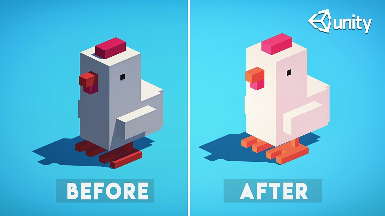
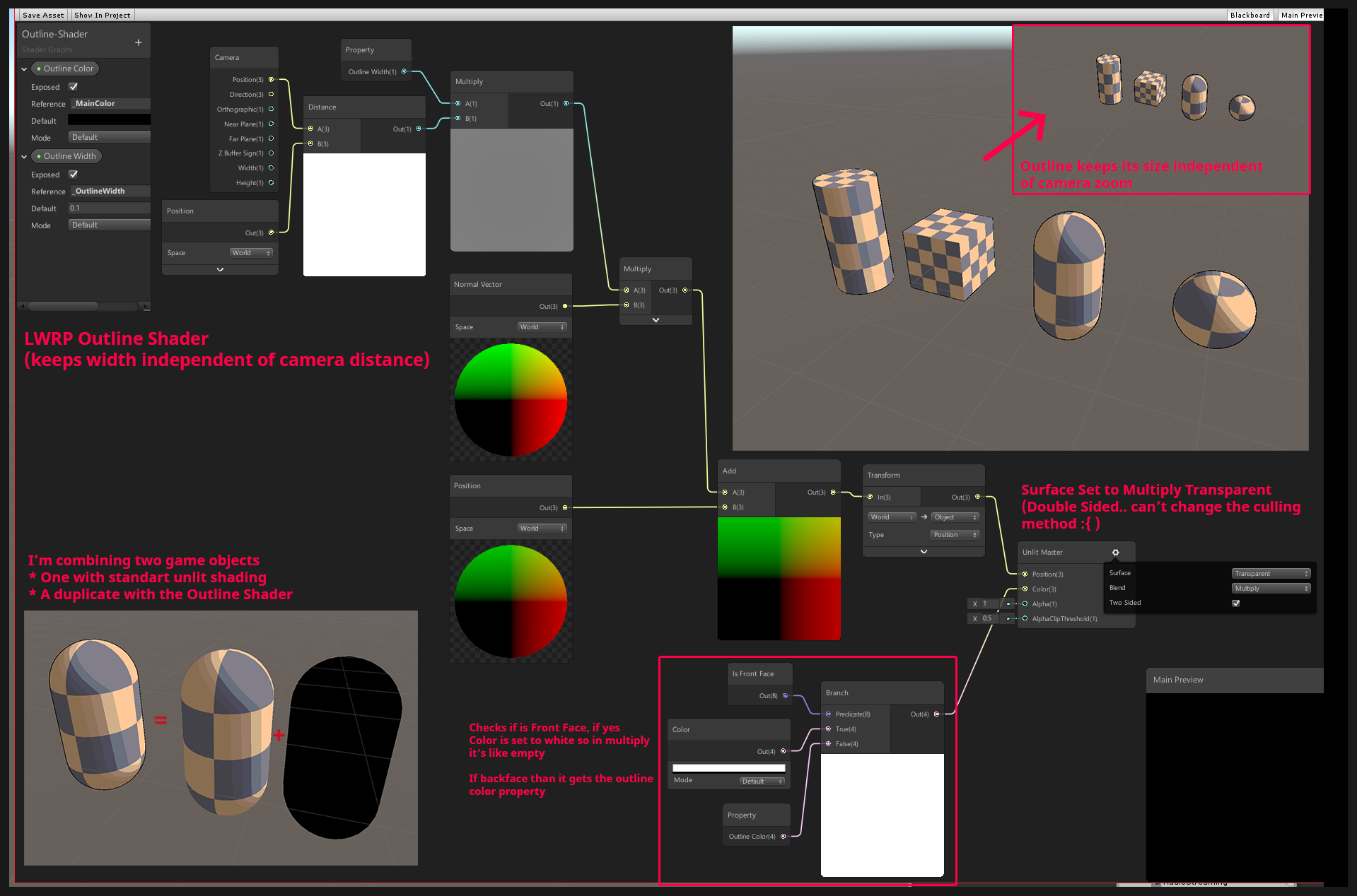
Hi all ! I'm in shadergraph making a quick outline shader by duplicating and displacing toward the outside my mesh. (multiplying normal) , now I need to render first the actual object that needed the outline, or set the outline to backface rendering.
But I dont find any rendering priority order setting or back face neither :/
Any clue 🙂 Thanks ?
with shader graph?
@gilded portal if it's with shader graph, take a look at this thread
Unity Forum
[IMG]
Hey guys, i posted this on unity3d reddit but got no response yet :( so i'll try it over here. Here is the post:
I'm creating a lwrp shader...
thanks
cant have color in multiply 😦
its weird theres no rendering priority option 😮
you can set the rendering queue?
and does the graph from the forum thread not work?
the last one
@stone sandal you guys want more input for the SG stacks ? I just tried the current wip branch. I see that if I rename a property that's already on the graph, it doesn't rename the existing one:
these two are both same property (MainTexture and BaseColorMap)
as additional note, I really really wished you'd let me rename the property also on the Graph Inspector: now I have to move mouse to other side of the screen to rename the property and then again to other side to change the reference name
trying it in opaque or additive right now as multiply will work ok for black color only (?).
So you can set it to double face render but doesnt look like you can back face only. Im thinking... Inverting normals should produce this?
@fervent tinsel that first comment is a bug which we’ll start taking after the package formally releases for alpha testing, but the second note is helpful!
IMHO it could just show the property name just like the reference there as textbox
but it could just be me
it just doesn't feel very intuitive that I have to edit the names on two places
Hey, is there a way to pass a variable from HLSL shader to CPU bound ?
Help! all my shader files have started to be recognized as miscellaneous files in Visual Studio, and I get no Syntax Highlighting or Error Detection. so far I Tried several solutions suggested from googling but nothing seemed to have worked and my problem seems a bit unencountered even! as It's just the shader files that have turned to this...and my C# files seem just as well as before with intelligence/highlighting etc. This started happening right after I installed a bunch of Modules with VS Installer namely Desktop Development with C++ and Game Development with C++
my current workaround is using VS code instead.
Hey I posted this question or r/unity
Any help appreciated
reddit
0 votes and 0 comments so far on Reddit
@patent mountain thas a realy tricky question
aproch would be to write a comptue shader that can caluclate a distance map from a given point on the uv outwards
but i have not the slidtest idear how to do that.
@patent mountain maybe somting like this would be a way
https://gamedev.stackexchange.com/questions/149964/shader-floodfill-alogrithm

Game Development Stack Exchange
I'm new to openGL and shaders.
Is there a way to implement shader algorithms for floodfills?
Basically, I have a picture with outlines and i want to fill the insides of where the user touches it
@regal stag @lavish sierra @red swallow Thank you for the help with sprite UV/vertex displacement last week, just had time to test your guys tips and it's working.
@regal stag your example of offseting the UVs worked perfectly. I even tried to modify with Step node after the mask from the UV to see how that would influence the displacement, really cool learning with that example. Thank you again!
np! Glad you got it working
Guys I'm trying to split a model (painted in RGBA vertex paint) into 4 channel/masks in the shadergraph
but I noticed that the Alpha seems not working like the R/G/B
can somebody help?
What do you mean that A doesn't seem to work like RGB
maybe it's not picking up the alpha channel during the import
Maybe there's something wrong during the export/import step of your workflow @silk sky
Have you tried re-importing the model just to be sure the alpha channel was exported correctly?
re-import into Maya, I mean in this case
I cannot find any options regarding the Vertex export
but at least the RGB surely got exported
here's the model
as you can see the vertex paint on the body is transparent
thats him in Unity
the Alpha channel for now influce the whole model
Your shader is colouring where the alpha is 1, not 0. Just like the other channels, colouring where red was 1 for example.
If you want the inverted result, which would be easier for painting probably, you should use a One Minus node on the alpha value before it goes into the T input (or switch the A and B inputs around).
Then maybe the alpha isn't being imported or something, as Tibor suggested. You could check by dragging the alpha output directly into colour.
seems fine
Perhaps there are other colour channels in the transparent part too.
Texture import settings, check its info
maybe it's discarding the Alpha channel because it's set to Transparency
It's not a texture, it's painted vertex colours
oh, sorry, got them mixed up for a moment
the strange thing is that in the main preview it works
Ok i solved
I had to pass the alpha lerp to every other channel
If that works it's probably your transparent part has the colour (1,1,1,0), rather than say (0,0,0,0).
If that works it's probably your transparent part has the colour (1,1,1,0), rather than say (0,0,0,0).
@regal stag this also
in the Lerp part, you're maling a lerp between transparent black and the color assigned to the channel
lerp between solid black (0,0,0,1) and the channel color
It may be easier to take the alpha as the T to a Lerp, with A as the combined RGB value and B as the alpha colour * intensity
making*
Rather than adding all the RGBA channels
That way, it doesn't matter what is in the RGB channels, the alpha will always override it. That depends if you want that blending in some cases though.
for now i just want solid colors
This is what I meant, set W to 1, just a gut feeling
Nah, the alpha of the colours isn't actually important as the final albedo input is a float3 so it's getting dropped anyway
Instead of adding the alpha-colour result, try this
maybe still with alpha -> One Minus -> T, or switch the inputs.
Just thinking out loud: this should work because the Alpha channel already excludes the other channels, so in case of a Lerp the other channels that have already been processed will be left untouched, while the alpha painted parts will get painted with their palette color, right?
Assuming the channels do not overlap with each other
Yeah, it's masking based on the alpha, so alpha=0 will show as the combined RGB channel results, while alpha=1 will show as the alpha colour, regardless of what's in the RGB channels
at this point, the whole process can be simplified by putting lerps in cascade
I'll cook something quick in Amplify
and I'll post the graph, different apps but the idea is the same
Basically, something like this should work, I think
it's just missing the intensity values
Yeah, that would also work
also, with a 4x1 texture it should also be possible to source both the palette and the intensity of each channel, but I wonder if it's more efficient than just sourcing vec4 vars in the inspector
Yeah, and gives you the ability to easily expand the colour palette further than four colours if needed.
Isn't lerp vectorized for "T" too? 😉
maybe I'm not tracking what he's after. But IDK why you guys are splitting all these nice vector operations out.
That's a good point
Why cubemap affect on material preview in project folder
and not affect on material in scene?
How achieve same result for material in scene?
Why cubemap affect on material preview in project folder
and not affect on material in scene?
How achieve same result for material in scene?
@vagrant rampart is everything set correctly in the actual material you have assigned to the sphere?
Also, you have disabled the scene effects, try turning them on
5th button from the left, in between "snap to grid" and "lighting"
@slow bear
while (i >= 0 && exit.distance < intersections[i].distance)
{
    intersections[i + 2] = intersections[i];
    i--;
}
Any ideas why I would get the following warning for this loop?
I verified that the loop condition is not always false. And I'm using the result directly for the output.
int i = intersectionCount - 1; @meager pelican
intersectionCount is initialized as 0, so when the loop is run for the first time, indeed it will be skipped entirely, however the whole thing is inside another loop and intersectionCount is incremented for the next iterations
However, even if I init intersectionCount to 10, so that even the first section will certainly be run, I get the same warning
OK so is the outer loop a constant?
IDK, but if it thinks it can unroll it, there's something going on. There would still be conditionals for each statement.
But if, say for example, the outer loop is 0 to 2 (so 3 itterations) and it can determine that i gets incremented 3 times in the outer loop, maybe it makes cases for 0 (because it can tell the first one won't happen) and then a set for i = 1 and a set for i = 2. And the "loop doesn't do anything" is for the first case. So it omits case 0. (which is i=-1)
Total SWAG.
I bet, just as a test case, if you put an if around all this to skip the first case (so if intersectionCount != 0), the message will change.
@meager pelican
no, the number of iterations in the outerloop is directly determined by a shader input
for (int index = 0; index < ObjectCount; index++) {
I'm currently trying to build a minimal reproduction case
Well, maybe it doesn't have to be constant, if it can determine it's initial value of -1, in the unroll. IDK. Try that if out of curiosity. The beginning of the while loop should be an if, basically. But ...hey...loop unrolling.
Weird
hmm, what.. you were right
what the hell
putting an if around it makes the warning go away
What I think it's telling you is "hey I unrolled your loops somehow, and one of the cases will never execute as written".
hmm, looks like it
or actually I'm not sure
are you saying that it's a short loop so it tries to unroll and the warning is supposed to mean "one of the unrolled iterations will never be run"?
I think this detection would happen before the unroll
Yep. Guessing. Since it can determine the initial values, or ending values, or whatever.
I'm guessing all part of the same process, as it has to analyze it to decide to unroll it.
Since it knows the index=0 is the start, and it knows that intersectionCount and whatever and i depend on the values.
Again SWAG, I'm not a compiler writer.
It might imply you can change your logic or conditions to speed things up.
hi guys, just random question so i see in most of game like this from BOTW, the env was single sided, is there's any purpose of that?, i assume double sided avoided because it's much heavier to render.
@wraith wing you are correct with your geuss. Normaly only the front face is viable for the player so the backface will never be seen so its not a good idear to render it if its never seen.
thanks for the explanation @knotty juniper
@wraith wing It can be useful in some cases to render both sides of a face, like with non flat cutout object or foliage, there adding additional geometry for the back fades does often make no sense.
I am trying to do post effects using a second camera and replacement shaders
I am following some guide (potentially outdated)
When I run this code with the culling mask set I see only the backgroundColor (black) even though I have objects set to that layer.
When I run the code without the culling mask I still see only black and when I stop the game my editor crashes.
What am I doing wrong?
IDK. Depends on what the ColorOnly shader is doing?
You could just supply the PP effect material as a parameter to the blit.
void Start() {
    camera.SetReplacementShader (EffectShader, "RenderType");
}```
https://docs.unity3d.com/Manual/SL-ShaderReplacement.htmlSo that's another way on the secondary camera if you want to try that.
its drawing the object with an unlit color, i changed out the shader for a few others it didn't seem to make a difference
hmmm, from 2020.2.0a13 release notes: Graphics: Added: New API to allow the implementing Custom Render Textures on C# side, skipping completely the builtin Updates.
Hey, I seek wisdom about dynamic splatmapping! The feature that I'm hoping to achieve is to paint an area to a terrain splatmap that is within a mesh that is intersecting the terrain and thus changing the texture on the part of the terrain that is surrounded by the mesh.
I was thinking that if I could somehow paint that specific area to a rendertexture I could then Graphics.blit that to the splatmap? I might be way off here and that's why I'm humbly asking for guidance.
Hi, is it possible to make 3D noise with the shader graph? In blender when you put a noise node you can decide the dimension(1D,2D,3D or 4D)
@golden crest You might want to Debug.Log(renderTexture); before the blit to make sure it's set properly. Also that last condition on the if? Should that be "a not" as in !renderTexture.isCreated()?
You are right, it should be a not. I will try the the debug.log I didn't know I could use it like that.
Hello I am trying to make a dissolve shader and I managed to make it work but when I go into the game view the shader is full of patchy black spots that aren't in the scene view. is there a way to find out what's wrong?
hello yall, ive recently started to try and get into making shaders, but from what ive found, there arent really any good tutorials on parallax depth. im wanting to create a translucent crystal but i just cant seem to find anything on this topic.
https://cdnb.artstation.com/p/assets/images/images/007/484/815/original/roderick-weise-crystal-small.gif?1506452716
heres a good representation of the effect ide like to create

if any one knows of any good tutorials on something like this, just @ me
@patent mountain maybe somting like this would be a way
https://gamedev.stackexchange.com/questions/149964/shader-floodfill-alogrithm
@knotty juniper Appreciate the pointer
Game Development Stack Exchange
I'm new to openGL and shaders.
Is there a way to implement shader algorithms for floodfills?
Basically, I have a picture with outlines and i want to fill the insides of where the user touches it
Is there a way to make a blur UI panel in HDRP
@drifting stone check this and the posts that follows it: https://forum.unity.com/threads/hdrp-shader-graph-scene-color-node-wont-render-sprite.671338/#post-5601904

Unity Forum
I am trying to make a blur shader for UI that blur the background and other game object in HDRP with shader graph.
And I followed this tutorial:...
Thank you
@heady jewel I made additional noise nodes here : https://github.com/RemyUnity/sg-node-library
Including 3d & 4d noises

GitHub
Node library for ShaderGraph. Contribute to RemyUnity/sg-node-library development by creating an account on GitHub.

Hey, I have a problem with double sided shader, the image show the problem, the orange & blue colors are a part of a mesh I put under the player (some part blend into the background, the green grass in this case).
My problem is, I try to mask the ball (you can see it inside the blue shadow next to the right foot), by using the orange part of the mesh, which is a cone, and the ball is inside it in this image, however, this view from the camera causes the camera to see the blue shadow, which has alpha on it, through it, it should see the cone, hiding the ball, however the shader just ignore the cone part, and cull it, any ideas?
I have both:
Cull Off
Blend SrcAlpha OneMinusSrcAlpha
Just for another reference, this is the mesh I am talking about, you can see the cone and the plane on top of it
The ball goes inside a hole (which goes inside the cone, and you can see the ball there in the last image)
A simplified version of my shader is:
fixed4 frag(v2f i, bool isFrontFacing : SV_IsFrontFace) : COLOR
{
    // This is used to project the background texture ontop
    // of the mesh in screen space
    float2 uv = i.screenUV.xy / i.screenUV.w;
    fixed4 col = tex2D(_BackgroundTexture, uv);

    // If it is a front face, add shadow to it.
    if (isFrontFacing)
    {
        float attenuation = LIGHT_ATTENUATION(i);
        float shad = (1 - attenuation);

        clip(shad - 0.05);

        float softness = lerp(1.0, shad, _Softness);
        col = _ShadowColor * softness;
    }

    // Used to mask stuff with 2D image
    col.a *= 1.0 - tex2D(_ScreenMasking, uv);

    return col;
}
Thank you @amber saffron !
If I have a normal 3d model, is it possible to transform it into something like this using a shader?

@ancient kelp extremely hard, but it could be done
I'm trying to cut out everything that's outside the sphere.
I was thinking of doing it with a custom function where all the other materials would get their alpha based on the sphere's location and then use AlphaClipThreshold to remove it.
Wondering what you guys think of that idea, or if there's an easier way to do it
So many ways to do this :p
Using stencil to make a mask ?
Indeed using the distance to sphere surface to do the alpha clip (you might want to complexify a bit if you want that some objects have transparency enabled). I would also recommand to directly disable rendering of objects that are fully out of the sphere from script
You should also disable the sphere shadow imho
Stencil would include things outside, behind the sphere
True, forget that then
Shader Graph doesn't have a discard node? If not, a simple custom node function that just compares the distance with the radius and discards based on that should work with both opaque and transparent shaders.
Hey, good idea ! I should add that to my library
It could just use the clip function actually and just need one float parameter
I know of the discard thing in HLSL code - I'm not too familiar with writing custom functions in Shader graph though
is it the exact same? @low lichen
or GLSL - whatever, the shader code thingy
discard(x)
The discard I'm talking about is the HLSL discard
Custom functions in Shader Graph lets you write HLSL
You could also just use the alpha clip threshold
I tried making sense of it @regal stag but I honestly don't understand it perfectly :p
If the AlphaClipThreshold is higher than the Alpha value, it discards the pixel
But I guess the custom function would have to pass the current pixel color through it to actually get included in the generated shader? If it doesn't ultimately connect to the master output, it just gets ignored, right @amber saffron?
It would still be a bit "weird" to implement, as clip(x) and discard() are "terminal" functions that don't output anything, and to have them compiled by shadergraph, you will need to output something from the custum function, and connect it to the master node :/
Yeah, it would probably need to be connected in somewhere
@regal stag since I'm working with a transparent shader alrdy it would clip the sphere itself, I wanna clip everything inside/outside the sphere
(I need both use cases)
I mean for the materials/shaders for the buildings, not the sphere
You wouldn't use discard on the transparent sphere
You could also do something as "stupid" as setting the alpha clip value to either 0 or an immensely big number, depending if the pixel is in or out of the sphere.
Should do the trick
yeah, that's the theory - but how to do that in practice is what im not succesful at
so I 100% can't do this using just a shader on the sphere? @low lichen I'd have to put the discarding/clipping on the shaders/materials of everything BUT the sphere?
Yes
How, in shadergraph, would a different object be aware of the sphere?
You'd have to pass the sphere's position and radius to those shaders
You can't really add a gameobject to the Blackboard
Probably through a global shader variable
How would I do that? :p
One vector4 property is enough to hold that info, and you the set it through Shader.SetGlobalVector()
Shader.SetGlobalVector("_SphereInfo", new Vector4(x,y,z,radius));
Inside a custom function that is called inside the sphere's shader?
Then make a property in the blackboard of the type Vector4 with the reference name set to _SphereInfo or whatever you want
No, in a C# script
So in a empty gameobject with a monobehaviour script in like a Start Function that would have a reference to the "clipshader" (that's applied to everything except the sphere) ?
It's a global variable, so you don't need a reference to the shader
When we write Shader., it's not a reference to the shader, but the Shader class. It's a static method.
And if the sphere moves or changes size, you'd have to update that every frame, or every time it changes
Luckily it's static 😄
Here's an example of the shadergraph using alphaclipthreshold.
Could also use a Step node, with In as Distance and Edge as the Multiply output, and just leave the AlphaClipThreshold at something like 0.5.
And then based on that Vector4 change the Alpha's of the buildings and clip it that way?
Why do you divide the radius by 2 ?
isn't he dividing the X position?
Might be because of the default unity sphere scale
It's the A component, as in w
oh, as in RGBA
Also, remark based on your screenshot : this works only for ONE sphere
gotcha
You'll have to chain these nodes with multiple vector inputs if you want to have more
Basically the idea is to cut the inside out on 1 sphere. cut the outside out of the 2nd sphere and combine them
but I can for sure continue with this
one edge case I'm getting is that basically anything and everything that I want to be cut/clipped will have to have this shader applied to it
but what if it's using a transparent shader to begin with, think of glass or something
That's where using the alpha clip threshold falls apart
Since it forces you to use the Alpha output which is also used for transparency
That's why I suggested to use the sphere distance to set the alpha clip to 0 or 1
So a distance check would then be better , as in a custom function
0 beeing : I see the transparency, and 1 beeing fully clipped
and no need for custom function to do this
Oh , instead of hardsetting the alphaclipthreshold to be "If it's alpha is lower than 0.5, discard" You make it dynamic in saying "IF distance to circle and lower than 0.5, then discard"
This helped tremendously Guys! thanks! 😄
(atleast in theory, still have to do it in practive :p
Some sample to do it only with the clip output :
I'm trying to think of a way this effect could be done without requiring custom shaders on everything.
In the case of wanting to clip everything outside the sphere, what about using a combination of a stencil mask and the depth buffer? The stencil mask would cut out everything outside the circle and to cut out things behind the sphere, render an inverted sphere into the depth buffer before rendering everything. The depth value of the inverted sphere would reject anything behind the sphere even if it passes the stencil check.
But he also wants it the other way around
You could do it the other way around too, but you couldn't combine them I'm pretty sure
It might be possible by having a full depth prepass and using two stencil bits (back and front faces of the spheres)
But having a global shader is probably easier.
Yeah, and a custom shader lets you do more interesting combination effects
Some sample to do it only with the clip output :
@amber saffron What is it exactly I'm seeing here? I don't see a cutout of a sphere?
or am I blind af?
Well, a sphere cutting a plane makes a round hole, right ?
And the shadergraph material above that is applied to the plane?
If you invert the step inputs, you invert the mask
I'm trying to think of a way this effect could be done without requiring custom shaders on everything.
In the case of wanting to clip everything outside the sphere, what about using a combination of a stencil mask and the depth buffer? The stencil mask would cut out everything outside the circle and to cut out things behind the sphere, render an inverted sphere into the depth buffer before rendering everything. The depth value of the inverted sphere would reject anything behind the sphere even if it passes the stencil check.
@low lichen I'll be honest with ya. You kinda blew my head out with what you said. lol. The other solution I seem to grasp better
If you invert the
stepinputs, you invert the mask
@amber saffron Thank you! 😄
you probably do not have a render pipeline properly configured
there are configuration instructions pinned to #archived-hdrp
if you're using the default pipeline you will not be able to use shadergraph
There is this brackeys tutorial
Let's learn how to render characters behind other objects using Scriptable Render Passes!
This video is sponsored by Unity
● Download Project: https://ole.unity.com/occlusiondemo
● More on Lightweight: https://ole.unity.com/lightweight
·····································...
and what he does is he uses the 'render objects' renderer feature in URP to change the look of some objects in the scene. He configures the layer, so only objects on a specific layer are affected, and then he specifies the material of the object (the dither effect on the right)
he then applies it to a bunch of NPC's in the scene
but what if I want some objects to show a red colored dither effect, and other objects to show a blue colored dither effect
would I need to do 2 renderer features with 2 materials and 2 layers? Or is there a smarter way?
is there some way with material property blocks maybe where I can still use 1 renderer feature and 1 material, but the renderer itself can still set some custom properties for the material
maybe this is more #archived-hdrp related though
@devout quarry If the renderer has a material property block on it, it will override properties on the override material
So yes, you can have one renderer feature with one override material with a color property and override that property with a material property block on the renderer
SRP Batcher won't batch that though
But for example in the video, in the 'override' slot for the material, he adds some sort of dither effect material and then he adds all the objects that need to be affected to a certain layer
So if that dither material has a color property
then as you say, on the renderer I should override that property with a material property block
but how exactly? because I didn't put the dither material on the object right? I just assigned it in the renderer feature
A MaterialPropertyBlock just stores the property name it should set and its value
so I would need to add a script to each object that sets the material property block?
if I need a custom color on that object
You would need to add a material property block on each renderer you want with a different color, yeah
Whether you do that in a script on the object itself or some other script is up to you
right
but let's say I'm only working with 2 variants, or 3
am I better of just working with renderer features, 2 materials and 2 rendering layer masks?
in terms of performance
That would batch better, yeah
And so I would be using the new rendering layer mask system
is it slow to switch rendering layers at runtime?
I doubt it's something Unity is caching. It's probably checking the layers every frame, so I think you're just setting an int value.
I'm not sure if this is a lighting question or a shaders question, but how could I remove that seam between these two meshes? They're loaded in at runtime so I can't manually configure them to line them up. I'm using URP and shadergraph with a PBR node on each of them.
Just combine the meshes @atomic glade
I can't. They're loaded at runtime from separate files
Ah, I didn't know there was a function for it
I'll look into that, I think that might be what I need. I'll just need to find a way to know which meshes need to be combined
You will also need this, probably https://answers.unity.com/questions/231249/instanced-meshes-are-being-offset-to-weird-positio.html
Unity is the ultimate game development platform. Use Unity to build high-quality 3D and 2D games, deploy them across mobile, desktop, VR/AR, consoles or the Web, and connect with loyal and enthusiastic players and customers.
So, it looks like these meshes are already part of a single mesh filter as separate submeshes. Is there a way I can get rid of this seam while maintaining them on separate submeshes?
Each of those submeshes has metadata based on the source files it was generated from and if I combined the meshes I wouldn't be able to show an individual submesh's metadata
Even without keeping them separate, I just managed to combine all the submeshes together and they still have a seam. So now they're on the same mesh and submesh and I'm still getting lines where the divides used to be
Hello. my question is how to deliver a vector array to a shader? I want that on the water after the ship sailed there were waves. Does anyone have a ready-made solution?
look up compute buffers
the other alternative is to treat a texture as a lookup table
Shader graph have compute buffer?
not sure, let me look
ah, feature is on the roadmap for now. You should use a texture as an array in the interim.
1D Textures should already be supported, or you can use maths to map a 2D tex to a 1D tex space
wait, that's the VFX roadmap
after seeing a lot of guides now I understand how to make waves. just noise and time. but that would leave a trace from the ship or something else. Now I don’t know how to do it. maybe you know?
no, I don't, sorry.
As for the buffer in SG, it looks like it's possible with a Custom Node, but you'll have an easier time with the texture method.
The upside of exposing a buffer read node in SG is more complex types, the texture as array method is simpler