#archived-shaders
1 messages · Page 137 of 1
This just proves a universal constant of physics and probability: Roseanne Roseannadanna was right "It's always something". (Old reference).
P.S.
I think it was grey, but the opaque texture WAS enabled.
It seems to be grey with the Unlit, but black with the Lit one
Which seems a little strange, wait nvm, I have no lights in the scene, of course it's black 🤦♂️

Unity is the ultimate game development platform. Use Unity to build high-quality 3D and 2D games, deploy them across mobile, desktop, VR/AR, consoles or the Web, and connect with loyal and enthusiastic players and customers.
found this
as a separate thing
That's not it though, as it works in "regular" URP/SG (as I showed above) in a 2D project. It's specifically the experimental 2D renderer that appears to be at issue.
Anyone know where the preview and settings have disappeared to in the PBR Master node?
how would i set a piece of a mesh to be transparent?
Either a cutout or a texture piping to your alpha channel. I think.
I got it!
how would i get a line to appear behind?
like this
nvm
found it
im dumb
wait i take it back
i ticked two sided and now i'm getting this weird effect
@onyx lily Are you using the URP? Just found out that the cut-out mode is on the standard shader, which isn't compatible with the URP.
@onyx lily Just figured it out. Are you still stuck?

Are you looking for something like this?
- Create a texture, set the alpha value where you want a hole.
- Create a material.
- Set the shader to Universal render Pipeline/Simple Lit.
- Set Surface Type to Transparent.
- I had to set Render Face to Both, you might not.
- Tick Alpha clipping (this is the magic).
- Set Base Map to your texture with the alpha values.
- Strut around and bask in your glory.
@onyx lily Here's my texture & material for reference.
@dusky yarrow wdym by "set the alpha value where you want a hole"
i already have the hole, if that's what you eman
mean*
the only issue is it looking extremely weird
Open to texture, it's just a png with a hole.
would this node do?
Wouldn't using twelve meshes be easier to get exactly what you want?
well, i'm looking for the cube to be able to be warped
No need to use a custom shader, you can use the build in Lit ones.
Have you tried the steps I wrote above?
i don't really understand them, that's why i'm asking for you to elaborate on the first one
Use the texture I posted as an example.
@onyx lily Hollow cube using the URP shader.
sorry for the late response, thanks! I'm going to try it now!
it worked! Thanks so much!
@dusky yarrow
wow
Only the strutting left to do then @onyx lily.
What unit is the _Time variable in? All the documentation say is some variation of Time since level load. Is it seconds, milliseconds, ticks…?

GitHub
Scriptable Render Pipeline. Contribute to Unity-Technologies/ScriptableRenderPipeline development by creating an account on GitHub.
It's floats, so units are seconds with fractions. (Sorry, duplicate)
Hi guys, tiling and offset node in shader graph tiles my texture according to the mesh's height and width. How do I keep the aspect ratio of my texture?
spotlight cookies in lightweight?
@tall chasm Well, if you can get your mesh's height/width (you'll have to pass it in I think) you can use that ratio to adjust your UV's. Can't tell you the formula off the top of my head but maybe take the output of the tiling and offset and multiply by the other ratio, accordingly. It would be a ratio of your mesh's x to the texture width, and mesh's y to the texture height of some sort.
@meager pelican I'll give that a go
OR I suppose you could mean something different...like per triangle mapping of an entire texture, by world-space size or something. Not sure what you're really after. But yeah, resizing the mesh (say a quad) will stretch the texturing of 0->1 UVs. So you're really after a calced tiling I think.
Also make sure you set the wrap mode on the texture if that's what you want.
@tall chasm
@meager pelican
That's a scrolling pattern
The thing I'm trying to achieve is for it to remain circular like its original aspect ratio
Is this a screen space effect? @tall chasm
What do you mean by screen space?
Is it applied to a 3D object in the scene, or the camera view?
Ohh
It's not too clear from the image
Is it always going to be fullscreen? If so you could use the Screen width/height to determine the correct scaling, rather than sending in the width/height of the UI component
Yes always fullscreen
And do you want the image to scale with the UI size, or always remain the same scale regardless of size?
I want the aspect ratio to be correct for the image. Meaning the A button sprite now looks squashed. I want it to remain as a circle. This scrolling pattern is a background so I guess the size remains the same for different screen resolution?
No matter what master node I use in Shader Graph, if I later use the shader in a particle system, then I can't change the particle color.
Which master is the right one for particles? Or do I need to set particle color up in the Shader Graph itself somehow?
@autumn bramble Is this for the shuriken particle system? If so, it uses Vertex Color, so you need to use that node in the graph to take into account the particle system colour.
It's for sprites that I animate through the particle system with a sprite sheet
@tall chasm Try this. It uses the screen position as UVs, using the screen width/height ratio, instead of the normal UVs from the UI object.
@regal stag It works with Vertex Color, thanks alot! 🙂
@autumn bramble As a note, the Particle System component also allows you to send in additional data using the custom vertex streams option under the Renderer tab, e.g. AgePercent which goes from 0 to 1 over particle lifetime.
That would add "AgePercent (TEXCOORD0.z) to the list, which in shadergraph you would use the UV node on channel 0, Split -> take Z/B component
@regal stag that worked beautifully!! Thank you so much man 🙂
Btw
How'd you group and name it Spreenspace UV?
Dragged a selection, right-click Group Selection.
Damn, color is working, but the Alpha over lifetime is ignored
@autumn bramble The alpha over lifetime should be in the alpha component of the Vertex Colour, you may need to Split it and take the A output
Thank you @regal stag I never knew grouping was possible. Now my nodes seem more organized 🙂
One last question, adding space between tiles is not possible right?
I really think I have somehow messed up my project - everytime I use the Shader Graph with alpha /opacity of some form, nothing seems to work as expected ^^
@autumn bramble Have you set the master node to be transparent?
@tall chasm Hmm, it might be possible. The easiest method would be using a texture with extra padding though.
@autumn bramble check your texture type too. Working in default most of the time works fine. When I changed to sprite ui mode it broke for me
yes it's transparent and I split the alpha from the vertex color. But alpha over lifetime is not applied, and also I seem to have the same problem as yesterday (particles look like they are slightly transparent, even if the should be fully opaque)
@regal stag Ok got it! Thanks 🙂
For this project I set the Universal Render Pipeline - could that be the problem?
@tall chasm Well, ya could have told me that! 😉 But good work from @regal stag - the screen space height/width is what you can use for full-screen. Then you don't have to pass it in, Vindorable.
Otherwise, yeah, you adjust UV's according to that ratio.
@autumn bramble For this project I set the Universal Render Pipeline - could that be the problem?
Doubt it.
Try outputting the alpha into the colors to debug it. Set RGB to whatever you're currently plugging into alpha (maybe swizzle it), and set alpha to one. And see what color you get.
@meager pelican sorry! I'm a little bad in explaining it since I'm still new to shaders. I still appreciate your help!
lol That's OK, no harm. 😉 :p I didn't mean anything by it really. It still ends up as a ratio of the "mesh"'s size, the thing that makes it easier is that you can calc it from screen size. (aspect ratio).
Musing...I wonder if there's a way to get the screen-space size (X and Y) of an arbitrary mesh of n triangles after clipping...you could compute it for one polygon, but IDK about the whole mesh, particularly with clipping.
Lol I have no idea 😅
trying to create a circular gradient background but it's not showing me anything
The alpha components of the colours is 0
yeah the color is totally transparent
For some reason, shadergraph defaults to 0,0,0,0 😓
Ahh I see
youd think it would do 255,255,255,255
Spent 30 mins connecting and reconnecting the nodes hoping something might work just to realise alpha was 0 lol
Well, (1,1,1,1) in terms of the actual Color/Vector4 value, but yeah. It would make more sense to default to that
For most other master nodes it doesn't matter that much, as the Color input is a Vector3 and it has a separate alpha input. But for the Sprite ones, it's all in the same input.
Ahh ok I understand
Hey friends, I have an age old question about sorting, but specifically with regards to sprites and shadergraph.
The gif is pretty self explanatory, and I noticed that there is a new (?) Rendering Layer Mask option on the sprite renderer component. Is this what I should be looking into?
Hi! Anyone knows why the cube is cut in the middle? Shouldnt be something progressive?
@grand jolt "Cut in the middle"? "Progressive"?
You're outputting to alpha. You're getting zeros in black areas, right?
@tame topaz Looks like backface culling?
@tame topaz tried a different material on the spriterenderer something with a different shader?
@grand jolt It's "cut in the middle" because your AlphaClipThreshold is set to 0.5, and so alpha values below that will be clipped. If you don't want it to discard pixels, set it to 0.
@regal stag Thx, I didnt see that
What is "Tangent Space"? I'm trying to understand why this gives me a pure green surface (green is the centre pixel of the input).

What is tangent space, and more important, what is its relevance to game design? In this in-depth feature, FXLabs programmer Siddharth Hegde discusses both tangent space and its practical uses, and why it is such an important consideration in many of today�s pixel shaders.
It's got matrix algebra. 😢
Yeah. ;)
I think of tangent space as what you normally see normals mapped to in a normal-map. If it were mapped to world space it would be different for each orientation of the object, and for object space it would be all over the place. So it's relative to UV's, and orthogonal to the surface normal and binormal. There's tangent and bi-tangent and normals. It's why we get those purple normal maps. Basically, tangent space is face-normal and binormal relative.
I think. Here
Well, that didn't work. lol
Does someone know how can we do a blurring effet shader?
Scroll up to yesterday. In what pipeline, using what tools and what renderers? Whole screen? Partial object?
Also see unity tutorial on Shader Graph and distortion.
I posted a simple example yesterday.
But we couldn't get it to work IF you're using the current version of the experimental 2D renderer. But in normal URP it worked. Used the scene color node.
I'm not doing anything related to the experimental 2D renderer
That sample code I made is a pretty crappy blur, you can do better, but it shows the basic idea.
And like cyan said, you can use a downsample if you don't need the high-res for other things.
hey guys please help me
i already asked it once lmao
so I want that black screen to be transparent
like a normal Fog of War effect should be
but I don't know exactly how to do that
since I never touched shader coding stuff
What exactly do you mean by "the transparency of the black screen doesn't look right"?
@analog surge About what sample code are you talking about?
it makes all the objects it overlaps change color or something @regal stag
it should just fade away
wrong carpe xD
but it doesn't
@final helm Sorry - Thursday at 8:12 Eastern Time. That's about where the discussion started.
lol
@regal stag And I also want it to hide some gameobjects even though the black screen is transparent, so they only show up when outside the black screen (inside the transparent mesh, the line of sight)
and I have absolutely no idea about how to do that
@formal tartan Sorry, I don't think I understand your problem or setup enough to be of help here. You mentioned in the image that someone else made the original shader for you. Could you not ask them about how to fix this?
I can't talk to that person anymore
the shader is applied to a material which is applied to that black screen sprite
i didn't mention that
so the material's transparency is lowered when i lower the shader's alpha value
right?
I would assume so, but it depends on how the shader it setup. Changing the alpha did seem to affect it properly in the second image though. I just don't see whats "wrong" with it.
what's wrong is that it is not what i want it to do
i mean it sounds like it is
but it does something completely off
Right, but I don't know what your intended result is.
my intended result is the black screen being slightly transparent, like in the second image but without it affecting the walls or any other objects it overlaps
see
in this example i got off the internet
the black screen makes everything appear darker
but you can still see it though the black screen
and then when the black screen ends (in the cutout) everything is displayed normally
that's what I want
Is it possible to read a variable from a shader? ive searched up and found Shader.getFloat but it doesnt seem to work.
@formal tartan I think in that example image, the grid and walls are likely being rendered after the "black screen". The screen itself is not transparent. If you don't want walls/certain objects to be affected, render them after the black screen. If each object is a separate sprite, I think they have sorting layers / order in layer on the SpriteRenderer? (not too sure, I'm not too familiar with 2D/Sprites).
@brave sable That's going to read a value from a material property.
What type of thing are you trying to "read from a shader"? Is it a compute shader?
dont exactly know the difference but its an unlit shader, im trying to read the distance from the camera to an object.
You should already know that on the C# side....
@brave sable Could you not calculate that in the C# script instead?
@regal stag Ok I got the idea of changing the order in layer setting on the sprite renderer component of the black screen and now I achieved the effect that I wanted, thanks!
no, everything is rendered in the shader since its a raymarched.
I watched something for the blur and I've done this, but the result is still completely white opaque
what should I add more to get a working blur?
although it might be possible to send object info from a normal script.
@brave sable Oh, lol. Oy. Then how do you specify the object from which you want to get the distance?
You could try blitting the depth buffer to a texture and read the values back. But that's a scene depth value.
There's probably 100 other ways, but I'd have to know your architecture/design.
@final helm What I did in the example was use a scene color node, and multiple samples, averaged.
@final helm That looks more like distortion than blur.
But in order for the Scene Color node to work properly, if you are using LWRP/URP though, make sure the Opaque Texture option is enabled on the pipeline asset, and it needs to be Transparent (or the shader itself will be rendered to the texture, and cause some weird rendering loop...).
If you aren't using the opaque texture for anything else then, you can specify a downsampling in the pipeline asset which might work as a blur effect. If you need to opaque texture for other things at full resolution, then you'll need to use multiple samples and do the blur calculations yourself, like in @meager pelican's example.
'kay
yeah idk, im kind of new to unity and shaders in general. i just followed a tutorial for raymarching and made slow progress.
lol I just created a mirror, well
if you want me to i can send a pastebin of the shader.
but idk how much that would help
Maybe answer @regal stag 's question first...do you need the scene color stuff at full res for other things in the future? (You only get one copy, and you have to pick a resolution).
Sorry, there were a lot of info
not sure to understand, do you mean if I care about the details of the blur?
It might be easier to just use the opaque downsampling as a blur, until you need the full res opaque texture for something else.
I don't understand your point? What would a full-res texture be useful for?
to be clear, I just want to blur the screen as background for pause menu
The full-res opaque texture is useful for things like looking through clear glass, where objects behind are slightly distorted.
Distortions is the main use case, I'm not sure if there's any other reasons to use it.
If you want to blur the entire screen, couldn't you use a post processing effect instead?
But what would be the texture? the glass texture? like a 2048*2048 empty texture? I don't get it lol
oh, I will take a look
The "opaque texture" is what the Scene Color node gives you. It's a texture containing a capture of the screen after rendering opaque objects. (In LWRP/URP at least. It's different in HDRP)
Ah ok
I believe the downsampling option just makes that texture smaller, which as a result makes it more blurry. But once it's made smaller, you can't get that full resolution texture back if you wanted it for a different shader effect (as all shaders rendered by a camera share the same opaque texture / scene color output).
As I said, I just need the blurring effect as a background for the pause menu so it shouldn't bother anything else?
If it's just for a pause menu (and you want to blur the entire screen), post processing might be a better option. URP has a Depth of Field effect.
Okay, I tried changing values and so on but can't it be more blurry?
it's the furthest I can get
If you use the Gaussian mode, setting both start and end to 0 seems to be quite blurry.
If you need it even blurrier, you can use the Bokeh mode and adjust the Focus Distance. (I think the Bokeh mode is more expensive than the Gaussian mode though).
Indeed! thanks
can I modify it through code? (I suppose but well, we never know)
I did not figure out how post-processing works in URP yet
I believe you can adjust the Weight of the Volume script through code to turn the effect on/off. If you have any more questions about the post processing it would be better suited in the #💥┃post-processing channel though.
Yup 👍
Thanks @meager pelican. Didn't see your reply at the time.
using shader graph, there's pbr and unlit right? well, i followed a tutorial and made a cell shader using unlit. but now i need to use that shader with transparency (not with alpha cutout), is that possible on master unlit?
if not, how do i turn off the default lighting information from the master pbr so i can use it's transparency
The Unlit Master node has a Transparent rendering option. Click the cog on the master node.
hmm
then im not sure why this isnt working
oh hey i follow you on twitter!
i love your shader work : )
Thanks
here's this
Does your texture have alpha values? If you take the A component and put it into a Preview node, is there anything there?
oh it does. im dumb. i set the alpha cutoff to 0 and it worked
Yeah, and that. If the AlphaClipThreshold isn't 0 it will discard pixels below that alpha value.
Light cookies are "In research" for URP, according to the roadmap. (LWRP was renamed to URP).
is there a workaround?
I'm not aware of any, sorry
do i need to change back to the default render pipeline?
I know this is really trivial, but I just did my own vertex moving shader thing on my own! WOO. Big day.
So… Can one disable the vertex movement in the Scene window?
good job!
Does a shader let me draw outside the object space? The effect I'm looking for is a spark between two points. I was attacking it with a cylinder between them (then I realised that the primitive wouldn't work because it only has one segment in the Y axis). Now I think it might take far too many vertices to achieve the effect if I do it this way.
Should I be looking at using the UV so I can get sub-vertex coordinates in order to create fine movement of the glow?
@dusky yarrow You can offset vertices to any position, but it won't update the bounds of the mesh, which is used to cull the object when the camera isn't looking at it. (I believe you can set the bounds of the mesh manually using mesh.bounds in a C# script though?).
If you're looking to make a spark/lightning effect between two points though, I would look into using the LineRenderer component : https://docs.unity3d.com/Manual/class-LineRenderer.html
Thanks @regal stag. A shader was the wrong way to go about things then.
You'll likely still need a fragment shader to make the effect look good, but the LineRenderer would be a better solution than using a 3D mesh. (Like instead of defining every point in the line renderer, you could just define two points, and use a scrolling texture with alpha cutout for the zig-zagging to create a lightning effect).
There's 2D shaders supported now (from what YouTube has told me).
I suppose that would be the correct thing to use to add some effects.
Is the line renderer's line still jagged though?
You can make it jagged if you define multiple points (more than just 2). I've just edited the comment above though which is an alternative.
OK, I'll give that a try. Thanks @regal stag.
@dusky yarrow Why not just use the particle system? For one "spark" it's not a big deal at all (no overdraw or anything). You can call ParticleSystem.Emit() with params to set the direction vector and the speed/lifetime which you can calculate given the two points. No custom shader needed. Unless you want some real-special effect on it that you can't get from a flipbook or other texture/attributes.
I've been trying to change the stencil buffer via property blocks, i.e Ref [_Stencil] and changing the property. I'm trying to make the TextMeshPro (the 3D one) maskable, but it doesn't work. The new _Stencil value is passed to the shader, but the masking doesn't happen. When I apply the same changes to the material itself through the editor, the masking takes effect. Am I missing something?
I'm mostly curious as to why this happens. I could probably make a new material and replace the material wherever I needed it (though that seems to scale really badly), but I'm also curious as to why this happens.
Is it possible to do a shine swipe effect on a button using shaders or is this effect done using animated sprites?
https://www.youtube.com/watch?v=21yU1iHcelg
Something like this

Coin Glint FX result video
See how to do it step by step in this video:
how would i have one textre render in the shadows, but another render in the light?
like a custom cross-hatching
If using the HDRP, there seem to be no particle shaders for Shader Graph - which one should I use for alpha-blended particles?
Or am I misunderstanding something: can I use the other shader graphs, even if using HDRP?
@meager pelican what do you mean by a flipbook in this context?
Hey guys, I'm working on a shader, and as you can see, the offset works to move the uv's of the texture in shader graph, but it doesn't work in the editor itself. Does anyone know why? I'm using Unity 2019.2 with HDRP
does it work when you click play?
Nop!
really?
Because I was going to suggest turning on Animated Materials
but if it's not working when you click play, i'm not sure
That does sound like it would fix it huh haha, but no it unfortunately doesn't work when in play mode 😦
@fathom plinth It did fix it!! Thanks 😄
@dusky yarrow IDK what look you're going for. But the particle system will move and change attributes (size, color, speed, flip-book-frame) of your "spark" over time...that's what it's all about. And it can handle 1 or 10,000 particles. There's a GPU one too (VFX) but it's probably overkill for this and would likely be harder to set up and use for you. But, again, IDK your usecase.
what do you mean by a flipbook in this context?
Here:
https://www.youtube.com/watch?v=jzehPwTEHuE
I don't think I've done a particle shader in SG, I do them in the standard pipeline all the time. But IDK about URP/SG and particles. I suppose I should try it. But you may not even need a custom shader for a "spark".

making classic animation using unity's shader graph.
In this unity shader graph tutorial we will use the Flipbook node to trim a sprite sheet image (atlas) with animation frames, and always display a single frame from the sprite. then we will use the time node to change the frame...
@tall chasm Can be done either way. There's no "one way".
With a shader, you'd animate the specular light direction; basically a custom lighting calc. Or you could animate a super-imposed moving texture containing "highlights" over top of it. Etc. Etc. Etc.
@meager pelican Ok let me give the super-imposed method a try. I don't understand the first method
@meager pelican I get what you mean by flipbook now. Just a series of images played in sequence. Like I get from Aseprite.
Yep. Sprite-sheet animation, flipbook, etc.
The reason I mentioned it is that the spark-particle could change shape/form as it moved using that method if you wanted it to. That's separate from the size, and color settings which the particle system also animates.
The affect I'm trying to create is more an electric arc than a spark. Sorry, bad explanation on my part.
https://www.youtube.com/watch?v=_2LpCdhuOyQ

Several spectacular examples the explosive force of high voltage power, including uncontrolled arcing at high voltage power substations and a controlled demonstration.
Yeah I assumed that was the case, as you mentioned spark between two points. That's why I suggested the LineRenderer component.
There are likely other ways to achieve a similar effect, but that seems the easiest / most obvious to me
So you're psychic too. Cool! 😉
Haha, I think I'm just good at reading into people's words too much
Thanks both @regal stag & @meager pelican. The spark bit will come when I've figured this out (i.e. if I figure this out).
I'm exuding optimism, BanksySan.
There's many techniques for "lightning" too. Maybe use your google-fu and scare up some some examples. Not to counter what Cyan said at all.
There is also no reason why you couldn't use the flipbook idea, and apply it to animate a lightning effect on the line renderer.
regular ass type
so a classic "Texture -> Sample -> Master" should work?
oh wait I'm retarded
i need to lerp that
👍
If you have a greyscale texture / mask, it would usually go into the T input on the lerp to interpolate between two other values (if it's just black/white it would output A/B), is this what you mean? @silk sky
No problem
I guess?
It's better to just ask a question if you have one, I'm sure others can try answering it too
So I have a transparent object, in it there's a inverse fresnel wich work as sort of light pulse, using and HDRI color
problem is even if Intensity is high, the light effect doesnt really comes out of the shaded object
you put it in emission?
yes sir
now it doesnt actually generate dynamic light, its an effect, and needs something like bloom to make it shine
Yeah, URP doesn't support realtime emission. Bloom post processing is the best way to make it look good.
while I think the default unity shaders emissive properties can be baked or whatever theres no realtime GI stuff
I need to access to a shader color and switch it in game. problem is when I exit the scene from editor the color doesnt turn back to previous one
Don't understand what's with this error
the shader needs a _MainTex
it looks like it just has some Colors
just assign _MainTex as a reference name
@tall chasm Just create a Texture 2D property on the SG blackboard (exposed I think) and name it _MainTex in both places (I think it's called reference).
name isnt as important as the referencename (one is a "pretty" name)
@silk sky When you modify material properties in the editor game mode or edit mode, they "stick" in the asset database. You're not modifying a copy, you're modifying the actual asset. It's not like the other stuff that gets serialized and deserialized.
but the issue persist only in the editor right?
Yes, that doesn't happen in a build that I know of.
How did you modify it? In code or by-hand in the editor?
@tall chasm
@proud axle , @meager pelican Got it. That fixed it. But my shader doesn't require a texture so I don't understand why do I need to add an exposed texture field?
It's a sprite, right?
it sounds like its required by whatever that thing was like a UI Renderer or something
something on the Canvas
The sprite system wants that texture reference because sprite materials need it to "work". (^^ or maybe UI like Tront is saying)
Yea it's part of the UI Canvas. No matter it's ok now haha
Dang psychics.
I'm 0 for 2 today.
Just for the record, sprites want that too. 😉
Ok I understand 👌 Thanks!
how do I make this in shader graph
Trying the make the button shine with your method @meager pelican
Just make it in a graphics editor.
OK, so you probably want the same UV0 to start with for both, BUT, for the scrolling one you do your time offset thing like you did above. Then you add the RGB values and normalize the result. I'd leave the alpha as it is from your original main coin texture. That's one way. It's an additive color blend, which works with your black (0) background and your white/gradient color stripe.
So basically the only diff is the alpha, if I read your graph properly.
How did it end up working for you? Did it scroll color across?
Creating a curve with the LineRenderer gives me annoying artefacts when the rate of change of the curve closes in on the number of vertices. Is there a way to smooth this out or do I just have to create a crap load of vertices?
Add more verts is the answer
@plucky bone is there a magic equation that already exists around the differential of the tangent and the number of verts?
Is this the correct way to draw a curve? With the LineRenderer, I mean.
It's one way
You can quite easily do your own mesh generation as well
But you'll probably end up with the same resutl
@tall chasm did you get it working?
What's wrong with this method?
void surf (Input IN, inout SurfaceOutputStandard o)
{
    o.Metallic = _Metallic;
    o.Smoothness = _Glossiness;
    o.Alpha = 1;
    o.Albedo.rg = IN.worldPos.xy * 0.5 + 0.5;
}
It's not compiling. invalid subscript 'xy'. IN.worldPos.y also fails. Doesn't worldPos have a y?
Show your Input struct
@meager pelican
struct Input
{
    float worldPos;
};```It should be a float3
So your guess was basically correct, there was no y, only an x, because a float has an x.
you can even swizzle the x like
...

o.Albedo = f.xxx;
@tall chasm Here's a tileable texture for your diagonal:
And a quick shader. I cheated with a custom node to make it less spaghetti and fit but you can duplicate that math easily enough with "real nodes". Make sure your textures are set to wrap mode = repeat for this to work. There's no normal mapping or other lighting in this or anything. So simple.
And of course there's many other ways to do this: Lighting calcs with normals and such for better specular highlights, and then there's generating it with another tool and using a flipbook animation. To name two.
@meager pelican This is not for a game object in world space
It's for UI button/coin/etc
So it's unlit, not affected by light
I don't have alpha channel for Sprite Unlit Master node
This equals to:
The moment I connect the Add
Button becomes weird
@meager pelican
@dusky yarrow Instead of relying on the shape of the mesh to make the curve, you can just use a transparent quad and do the sine wave in the frag/surf function.
Then it will always be pixel perfect.
hello, i'm writing a compute shader and wanted to make a mutable sampler which I would pass from CPU to GPU. is this possible? ComputeShader class doesn't have a SetSampler function and looking at the docs it looks like it always has to be hard coded.
@tall chasm The color in your pic is a vector4, so make sure the final component is set how you want it (the A in RGBA).
As to "button becomes weird" I guess I'll have to mess with a UI sprite when I get a chance, but that highlight looks added and tinted. I'll have to check on blending for the UI sprite. The "weird" is the black border? or what? Because the additive color is there. So confused as to what you want. Make sure you set the alpha component properly.
You may need to check the import settings on the "strip" texture and make sure you import alpha from it (or use alpha from greyscale).
hello, I have a problem
preview is working right but as you can see doesn't work on scene.
i don't know why? can someone elaborate?
@left pivot Where's the scene view?
@left pivot Is the problem that the outline is not as thick as the preview?
yeah
I can imagine it could be affected by the resolution of the view. The preview is much lower resolution.
Did you use derivatives, @left pivot ?
What outline technique are you using?
is there a work around? what preview shows is what I need.
it's offsetting texture up, down, left, right. adding together then adding to main tex.
How are you determining how much to offset the texture in each direction?
Just a fixed offset?
I have a vector1 that is multiplied by 0.01 otherwise offset is too much.
it's exposed to inspector
Are you able to get it to look the same in the scene view if you increase this offset?
Can you share the whole shader graph?
yeah sure
there are 2 group named as left but one of em is right one.
even this is unreadable though.
I can send the graph also, it's from a youtube tutorial. tutor's works fine. not mine though.
URP 7.1.8 with 2019.3.06f
Sorry but I got it done.
it was because of Color's alpha. I don't know why 😦
sorry to take time
shame on me
@naive mural Is it a set of simple changes such that you only have one or two or four permutations? It might not be too bad due to cache locality/coherence to multi read and then "just" select.
I wanted to make an option to give the ability to select any sampler state out of the ones available on unity. Bilinear/Point/Trilinear and Clamp/Repeat/Mirror/MirrorOnce. That would make 12 different total combinations. Atm i just declared the most useful 6 inside the shader and made a switch statement inside the shader to decide which one should be used based on an enum on the CPU's side. Feels quite ugly to do it this way though.
runtime
Yep, I knew you'd say that! ;)
IDK if it can be done. If it can, I can't do it in Unity. Maybe someone else knows.
I'm sure you've read this: https://docs.unity3d.com/Manual/SL-SamplerStates.html
So it's parsing the name of the sampler to get the mode. At design time you might be able to pull off a substitution (and I'm not even sure about that) but at run time...I'd be stuck with the same type of switch statement you're using too.
I'd nest it though, so the B/P/T would each contain another switch or ifs for C/R/M/MO and try a [branch] and see what happens. The compiler might just runroll all that anyway without further intervention. Oy.
You might want to see if dynamically changing the texture settings in C# will help. But that's texture instance specific, not sampler in shader.
i haven't considered changing the texture settings, i wonder if it can just be changed while the shader is being dispatched and then reset it with little to no cost. Will have to check it out. Thanks @meager pelican
Yeah, and at worst-case you'd have 12 instances of a particular texture's combinations, and could swap them out based on need. Still kind of sucks as you'd need multiple instances for texture X to have different effects for multiple objects.
IDK if it only stores the actual texture once though on the GPU, and just changes settings....IDK how the engine handles that.
Or like you say, do it on the fly, but then you'd f-up instancing or drawing, maybe. I'd have to play with it.
Because there's a one-to-one relationship between a texture and those settings, but IDK if it caches the actual texture bitmap internally and uses the one for multiple instances of a texture2D. And materials map textures to them. and batching is by material.
Instancing can pass per-instance attributes and there's a SetTexture() on a material property block.
@naive mural
Hi everyone, I'm currently working on a shader and I would like to know what is the relation between the base color and the red channel of the detail map (color desat) ?
@meager pelican Finished testing. If filter/wrap settings are changed before compute shader's dispatch and then reset right after dispatch, other systems are not affected, unless ofc the dispatch itself would need to be batched. Changing the settings is also not very costly, roughly 0.01f ms on my system
@ocean wren See the detail example in the surface shader. It's multiplied * 2 in their example so Albedo.rgb *= detail.rgb * 2;. You didn't specify the pipeline, but if you're writing a custom shader anyway....you can deal with it however you want to blend it.
hello, does anyone know how to create regions in HLSL code?
Guys, is shadergraph only broken for me in 2019.3? I created fresh project, imported URP, changed in project settings to use a render pipeline, reimported materials
but when i open up shadergraph, it says that current pipeline is not compatible with this master node
sorry my bad, i applied my pipeline to quality, not graphics
it works just fine now
@leaden fable You mean draw lines between the 3 dots?
@leaden fable What mesh are you using with this shader and how big is it?
It would be more performant to just draw a triangle mesh with a simple shader than doing SDF
In what context? Creating the mesh?
Nope, it's always a triangle with the same view distance
Then why not just pop a triangle mesh into the scene and make it a child of the character?
Is there a way to make it have no thickness as a mesh?
I'm using a shader because I want it to be one with the floor
You can have it be just one triangle face, which has no thickness.
I'm having kind of a funny SG bug
if I draw an 'EditorGUILayout.BeginFoldoutHeaderGroup' in my editor with text that is the same as an existing graph, the SG icon is put next to it
so in this case I do have a Caustics.shadersubgraph file in my project
Hi everyone ! Is it possible to input a material directly in a shader to automatically plug the maps ? like in the layered lit
In nodal system not in code
Not without a custom material inspector
Okay thanks @amber saffron
guys please help, trying to install modern LW shader to my old project but its not really workin so far, whats the problem ?
why i dont see my exposed shader varibles(color) and i dont see my shader on the dude get applied ?
i did all this
Did you do "save asset" in the graph window ?
oh... so that what cusing this problem
sorry im little dum first time using shader graphs
@dusky yarrow Instead of relying on the shape of the mesh to make the curve, you can just use a transparent quad and do the sine wave in the frag/surf function.
@low lichen That's what I was originally thinking, albeit with the shader graph. The problem was that the shader still relied on the verts being there in order to move them.
Hey @dusky yarrow - is this a situation where your effect will always be off in the distance and the user/camera view won't circle around the two points? Or can the user move around them? (or is it 2D)
@meager pelican Neither yet, I'm just trying to learn Unity and shaders. I don't have any use case for it at all.
It just seemed like a reasonable thing to use as a project to find out how things work. I'm very new to Unity.
It's all cool. The thing is that certain situations can make you select one solution over another, depending on needs.
@dusky yarrow I believe @low lichen was suggesting something similar to this. Using alpha cutout rather than offsetting any vertices.
The advantage here being it's not relying on any vertices, so the "resolution" of the curve will always be perfect, regardless of frequency/amplitude.
Would anyone here be willing to advise an absolute shader noob? I have a concept I'm trying to pursue, but I don't have the understanding to know what kind of things to research.
I have worked in Unity for a while so I'm not a complete beginner with the engine, just with shaders 🙂
You're better off just asking the question "to the world" and seeing what drops out of it. You don't have to ask to ask.
Fair enough, lol. Would this be the place to do that? That's kind of what I'm looking for.
If it's a shader question, sure. But see the resources (the stick pin above) first, or maybe a real general shader tutorial on YT or something so we don't have to write a book just to answer a question.
Fair enough. I have watched some videos on shaders before and I think I wrote some super basic intro shaders.
I just use google :D
Anyway, I agree, if you have actual question then ask that instead
I'm looking to sample a texture, then use that to "stamp" another texture onto it? Looking to take an albedo texture and use it to generate a texture with "brush strokes" based on the original albedo color. Does that make sense? What should I research to accomplish that?
@regal stag @low lichen That looks like what I was envisioning. I'll have a play with that technique. Thanks both.
@normal hedge IDK it depends on exactly what you want to achieve. But you could start with "masking" and "blending" searches.
@normal hedge you can look into custom render textures if you want to actually generate a new texture with a shader
if you just want to make a masking shader, that's a different thing
Quick googling suggests I'm looking more for the render texture option. Thanks! That's a big help already...
That's the output destination (and a good suggestion) but it isn't the methodology. You'll still want to know how to mask, blend/stencil, etc. unless all your stamps are "square". 😉 The CRT has a nice framework around it. But you still need to write a shader for the material.
Question. I'm trying to base a shader on light direction and had to use a custom function. In the tutorial I'm following they were able to get a main light node. I can't find this, even in the latest Unity?
pfft I wish there was a main light node
pisses me off it isnt included
@shell walrus you figure it out let me know plz
yeah for now I've had to make my own custom thing (very out of my depth here lol) figured it out via this https://connect.unity.com/p/getting-light-information-with-a-custom-node-in-shadergraph

Unity Connect
Custom Nodes are a formidable addition to ShaderGraph to extend its functionality
Here's a question. Is it daft to try making a cell shaded shader with PBR in mind? Do either roughness, normal, ao, height or metallic defeat the purpose of cell shaded?
hey i want to start using shadergraph
but it does not work with the universal rp so i imported the lwrp but i can not create a rp asset
Shadergraph works with URP
I don't know how you did set up your project, but shadergraph is imported with URP, and should work out of the box
ok thx i will try that
thx @amber saffron that worked
I have a question, I'm using a shader based on the white box shader from unity and some parts of objects (mainly the shadows from those objects) get this particular colour. It glitches whenever you move. Can someone tell me why only these parts get coloured and how I can remove this effect?
@celest flame Are you using URP/LWRP/HDRP? Forward or deferred? Post processing?
That kinda resembles the pattern of SSAO.
Are you trying to make an unlit shader?
What do you mean by the white box shader from Unity?
No it's a lit shader
You mean the Standard shader and the default material?
the standard shader yes
The Standard shader doesn't work on HDRP
I'm sorry - It's not the standard shader - It's the material that comes with the DOTS Sample project
@shell walrus Borderlands exists, so... not dumb.
https://cdn.discordapp.com/attachments/621316280321966080/677110744126455839/unknown.png
https://cdn.discordapp.com/attachments/621316280321966080/677110574953529344/unknown.png
Hey i have upgraded my project to urp and applied a bit of post processing (tried to copy the one on the first picture)
and now i noticed all those weird shadow glitches


@craggy patrol The first screenshot is realtime shadows? Not baked?
Nevermind, it looks like realtime soft shadows
The second screenshot is hard shadows, probably at a lower resolution so each pixel of the shadowmap is even easier to see.
how would I fix that ?
@craggy patrol Both settings are in the render pipeline asset you created when first setting up URP
ok thx
You can try just enabling soft shadows and see if it's good enough. If not, try increasing the shadowmap resolution.
Can you not use Material.SetTextureOffset on Shaders generated from Shadergraph?
You can, in some fancy way
I can create my own property and use SetFloat etc right, but was just wondering
Hook that into Tiling and Offset
If you know that the original syntax in shaderlab for texture tile/offset is [TextureName]_ST, you can define a shadergraph property using the same Reference as the texture + _ST
Then, in the graph, use this vector4 for a tile/offset node
So, for a texture with reference _MyTex add a vector4 property with reference _MyTex_ST and in c# use material.SetTextureOffset( "_MyTex", value )
How can I remove this effect from my shader? It keeps doing this with shadows on triangular spaces
I highly suspect that you have a NaN issue here. What are you doing in the shader ? Can you share the graph ?
I'll send it in 2 pics, it's unclear if I send it in 1
it's basically a modified version of the DOTS Sample material
Well, even with so many screenshot, it's barely readable
yes, I was afraid of that
it has the same design as the shader used in DOTS Sample, just other colours. But the original shows this spot aswell
@amber saffron thanks, thats cool
Apart from the glitched deformed character, I don't spot anything suspicious in this screenshot
the last ss was an example for the original shader
My shader fits well everywhere except on triangular plates where shadows fall, but I can't figure out why
It flickers when I move, this is how it is supposed to look like
If you could share your project that would be great to understand what is happening
i am using urp and for some reason it looks like ambiet occlushion is doing nothin
No AO in universal
or, iirc, it's not implemented yet with URP built-in post process stack (will come soon), and I'm totally not sure if it works or not with PP stack v2
mhhh ok thx
SSAO used to be disabled from PPv2 when using LWRP
I wouldn't expect it to be any different with URP
some user did hack it to enable it
it's not that it can't be run on it, it seems to be one of these artificial limitations because LWRP was designed to not rely on compute
yes, that's been on the works for months 🙂
like remy mentioned, it's coming soon
on URP product board, it's listed among short term things (within 6 months): https://portal.productboard.com/8ufdwj59ehtmsvxenjumxo82/c/15-ao-support
Support for ambient occlusion.
wish we had a similar board for HDRP as well, cough
HI guys! Who can help with vertex color shader setup for IRP ?
@proper bobcat whats your question?
generally you just multiply vertex color node with the texture sample results
@proud axle I want use only vertex color with in pbr shader type. If I'm using color as albedo and emissive colors still washed out
so vertexcolor node straight into albedo and emission?
over here on my machine that makes a pretty strong RGB
@proud axle
all supposed to be the same color?
@proud axle that supposed to be more saturated. That looks like wrong gamma range
well URP is in linear mode by default
not gamma
you can change it in the player settings I think
@proud axle thanks. I will try it
@celest flame you could try saturate or max 0 on the shadow applying to see if it clears up, it's either Nan or some negative value inverting the color
@proper bobcat if vertex color is coming through as linear it can just have a conversion applied in the shader, no need to switch the whole project to gamma
is there an easy way to do that @uncut karma ? the linear2gamma conversion?
There's a color or conversion hlsl file as part of the core render pipeline library that has all the methods
If shader graph doesn't do it it can be pasted into a custom node
I'm guessing there's also a define in urp or hdrp that says if vertex color is actual color or linear data but it would be buried in their shaders
In Shader Graph, you can also use Colorspace Conversion node. Linear > SRGB and vice versa
I have a weird problem with vertex displacement:
- I created a cube with many vertices in Blender.
- imported it in Unity.
- added this displacement shader graph:
But this is the result I get:
- Why would the mesh break up like that? I double checked in Blender: all vertices are connected.
- Why are the other Vertices ignored? Every side has around 20 more vertices (I'm looking for a kind of jagged rock effect).
Having the vertices connected in blender doesn't mean they are "really" connected.
When you have a normal split, it is interpreted in 3D engines as two (or more) vertices
Ans since you have normal splits (to distinguish each face), and you push the vertices along their normals, what you see here it 100% expected
Is there any way to keep the normals connected? Or: if this is expected, there doesn't seem the be much you could do with vertex displacement
you need to equalise the vertex normals
Keep them connected : don't use hard edges.
Or, you can also choose to not rely on vertex normals for the displacement vector
^ if the edges are smooth the vertices will displace how you expect.
Ok thanks Remy and Kink: no I have some stuff to try 😉
Ok beveling the edges didn't help, on to the next test ^^
@still orbit What do you mean by equalise?
I think not using the normals is the only option.
Like, a vertex on a cube edge is actually between 3 and 6 vertices (depending on the triangle layout/winding). Hard edge means each has a distinct normal direction. If all joining edges are smooth it means all those normal directions are equal.
Of course all that technically depends on mesh format, but thats by far the most common
Ok even if I dont use normals, but change the vertex object coordinates, I get the same result.
Is vertex displacement only viable for planes? Like a water surface?
"change the vertex object coordinates" can you elaborate?
yeah you can have a cube with 6 faces
or like a ton
it depends on UVs and normals
Dont think its just normals its UVs too!!
for a UVcube with 6 difference faces
you got
4 verts per side
24!
VERTS: 4 down, 4 up, 4 left, 4right, 4 front, 4 back
think about ur cube man

"change the vertex object coordinates" can you elaborate?
@still orbit I meant that I don't use the Normal Node in Shader Graph, but directly change the position of the vertices. But I understand now that this is no solution either, because there actually are several vertices at the edges 😉
@proud axle thinking about the unwrapped object is helpful, thanks
any idea on how i could invert noise in shadergraph ?
@craggy patrol Invert Colors Node?
kind of but not really XD
Depends what you mean by invert, but you probably want a One Minus node
i basically want everything that is white to change to black and the other way around
Yeah the One Minus will do that
looks inverted to me
I mean, the places that are black are now white, and vice versa
i quickly edited that in photoshop
If that's the output you want then you'd need to do this :
its -1 to 1
Use remap > (-1, 1) (1, 0)
or if you like how it looks and just want visual inverse Saturate > One Minus
I don't think it is a -1 to 1 range, the Gradient Noise output is roughly 0 to 1.
yea youre right, my bad
I think what they were expecting was due to the difference between linear & gamma colour spaces
yea it looks like it
@regal stag why do you say 'roughly' 0 to 1?
I've noticed I've had to use a saturate node after a gradient noise for good results in some cases
Hi Guys, maybe you have some clue whats going on: I have a postprocessing shader which does not really (not drastically at leats) affect the performance in the editor. But when I turn in on in a built version of the project its super slow. (Using the sam resolution in both cases) Maybe something is of the shader is compiled on the fly? I am using IL2CPP. Could be I am missing something fundamental, some guide what to read would help alread! Thanks 🙂 *Added resolution info
@devout quarry I said roughly because I've also noticed it can be slightly above 1 and slightly below 0. Probably something to do with how it's implemented, but I'm not sure why exactly - Maybe something to do with floating point errors?
@lethal steppe Have you tried profiling what's causing the performance issue?
Knowing at least whether it's GPU or CPU time would already be helpful.
I see good point, I will check and copare the two cases, thanks!
In the CPU usage there is a call in the build version: Gfx.WaitForPresentOnGfxThread - google told me it could be a lot of things. This is only in the built version, and eating like 98%
Other than that, in the GPU usage, the longest calls on the GPU are the Graphics.Blit() I do in my cameras onRenderImage(). In the built version its 61ms 95% in the editor its 5ms 38%.
I assume this could be a setting which is done differently in the built version? The multithreaded rendering (Graphics jobs) is not turned on. There are some differences in the hierarchy though - but I guess thats some default editor vs build differences.
Maybe got any idea what direction should I proceed? I will now just try different build settings and lets see.
@lethal steppe Is this on Windows, both the editor and the build?
yes both are on windows
The Gfx.WaitForPresentOnGfxThread is just the CPU waiting for the GPU to finish its blit.
its a gpu then 😄
Is it only 1 call to Graphics.Blit?
its 2 calls in both cases
How can i get the depth texture in hdrp?
@lethal steppe Can you do DX12? Try PIX on the build and look into what's going on. Or native (GPU manufacturer) debugging tools.
@kind helm using SG? Isn't there a scene depth node?
@lethal steppe are you sure it is your pp that makes build slow?
Like have you disabled it and it is fast again in build?
Hi everyone,
In HDRP, I'm just changing a material's color/emission via as a quick test:
model.material.SetColor("_BaseColor", new Color (0, 1, 0, 1));
model.material.SetColor("_EmissiveColorLDR", new Color(0, 1, 0));
model.material.SetFloat("_EmissiveIntensity", 12);
And while this is changing it, it doesn't actually update the model in scene view (though its material's properties are indeed changed). Is there something I need to do to push the change at runtime?
@tame topaz How is "model" set? Also, normally you want to change sharedMaterial and not Material. Depends on if you want to make a new material instance or not.
Also scene-view, and editor-view are different, as are edit mode and play mode. So I'm not sure where you're going on your last sentence. IN the runtime, ( a build), it will only change for the run, not in the asset database.
Right. I'm changing the material at runtime but it isn't actually changing it in any view. So while the material defaults as white on start, changing it does in fact update the material in the inspector. However it remains white in view until I manually adjust something in the inspector.
I'll give shared material a shot though
(OK, and none of this is really a shader question. But it's kind of related I suppose.)
What happens when you reference .material is that it clones the .sharedMaterial and then you're editing a local-copy for that object. It becomes an object-specific instance of the material.
The serialization and deserialization of the objects between edit mode and play mode...will restore the status of the .material and .sharedMaterial.
And when you modify .sharedMaterial in the editor (like when using ExecuteInEditMode) you'll find you're modifying the asset database entry.
Ah gotcha. Thanks for the explanation.
It might modify the material permanently. I don't remember offhand. But...one thing you can always do is to clone the material yourself and then set all your objects to reference it via .sharedMaterial. I've done that making a "material cache" for various reasons, so that if I already have a particular setting of a material, I set that in a new object's .sharedMaterial, and they all use that same one, but if I need to make a new one I do that too. That way they share when it's the same, and new if it isn't. (like dynamic object creation, but keeping batching when I don't/can't use instancing material property blocks).
But you should seriously consider gpu instancing and material property blocks instead of batching and messing with material settings if you can.
@tame topaz
It's for a coloured shot (4 player local interactive) so using GPU instancing sounds like something we want to do.
Good, then you shouldn't need to modify the material anyway. 😉 But your shader has to be instancing aware. SG is aware for things like color. And so is standard pipeline surface shaders, and you manually code it for vert/frag.
How would i create a "global" shader. I am using the URP. With global i mean a shader that applies to all Elements no Matter what Material they use. (e.g. an outline shader)
@terse nexus I think you'll want to use a UsePass SubShader https://docs.unity3d.com/Manual/SL-UsePass.html
So I must refer it in every shader? I dont quite understand the docs
And this will probably not automatically work with shader graphs, or?
I saw something called render features or similar. Is that maybe a way to go? If yes any ideas how?
@terse nexus This concept of applying the same effect on all shaders is not really a thing.
@meager pelican @shadow krakennto thank you for your input guys.
Yes - turning off the effect itself, makes the build go with 230fps. With the pp on it drops to 15 - also when I resize the window to really small size, the FPS goes up again.
I tried DX12 - same thing. I used PIX, which only works in DX12 mode but could not make that work with the Editor since Hub starts by starting Editor.exe ... So I dont really know what to compare or how to understand what it does display to me. But thanks again guys, I will continue with this tomorrow.
@terse nexus Your options are to add this effect to all the shaders you're using, add it as a post processing step or specifically in the case of an outline shader, you could render all the objects again but with an outline material as an override material.
That last step will probably double your draw calls, though
@lethal steppe You don't want to use it in the editor, use it in a build (DX 12 debug build). There's a shader pragma for debug symbols in shaders too.
See point #3 here (read all):
https://docs.unity3d.com/Manual/DebuggingShadersWithPIX.html
@terse nexus no Matter what Material they use. (e.g. an outline shader)
Shaders ARE materials, and materials ARE shaders. The material just holds the settings for the shader selected.
However, you can pass those material settings to a shader override as explained here:
https://docs.unity3d.com/Manual/SL-ShaderReplacement.html
It's done for a camera.
Does anyone know why I get this error? Shader error in 'Cel-Shaded RP/Unlit': 'TransformObjectToWorld': no matching 1 parameter function at Assets/Custom SRP/Shaders/UnlitPass.hlsl(24) (on d3d11)
UnlitPass is supposed to contain some code for a custom Unlit shader I'm working, here's the code. I include the required SpaceTransforms.hlsl from the core RP library in the Common.hlsl file.
@gritty linden So "../ShaderLibrary/Common.hlsl" is your own file that includes com.unity.render-pipelines.core/ShaderLibrary/SpaceTransforms.hlsl?
Yep
If you manually include SpaceTransforms.hlsl in this shader, do you get duplicate definition errors?
Actually, apparently it's because the Attributes struct doesn't have the positionOS parameter. Don't know why the compile error didn't state that but hey, it works now, so whatever I guess
I could have noticed that earlier as well, to be honest 🤦♂️
@regal stag I was reading your post about world space UVs and triplanar mappping. its really helpful! i'm using it for this https://i.imgur.com/LMYgHGH.png
however, it is a little weird that the ceiling must be the floor tile texture
would it be much more complicated to use another texture for the negative normals of an axis?
use different mesh/material for ceiling or make more complicated shader that takes the direction into account
I think checking negative normals would be easy then you have 6 direction triplanar
it's not difficult but you end up paying for two texture samplers instead of one
not a big deal it just feels that there could be simpler solutions but want to use one generic for all
Thx @meager pelican I'll probably just add a custom shader to every object than. It's easier in my case.
@meager pelican I need it for a custom volume so i don't have Shader graph (Unless you can now use SG to create post processing)
how do I turn a normal map image to a normal vector?
in shader graph that is
You can sample the texture and set the type to 'Normal'
like this? http://prntscr.com/r28ct4

What is it you want to do?
i have a function that requires a normal vector. I want to input that vector from a normal map image
I guess this does the job
Yeah, you should just be able to plug in the RGBA(4) slot
new problem :P
I have a vec4 with the calculated lighting and a vec4 with the texture. But the shadowing is to strong. How can i reduce its influence in the multiplication. http://prntscr.com/r293py
I just cant think of it although it should be basic math

@kind helm I need it for a custom volume so i don't have Shader graph (Unless you can now use SG to create post processing)
I don't remember what pipeline you're using.
But OK.
IDK why you can't use SG for post processing, but you end up making a custom shader anyway I think (IDK much about SRP's post processing, frankly). But I mean you could use a basic shader that shades a quad in screenspace, then view the code and edit it up into whatever the post processing requirements are for SRP. You know, start out in SG as a code-generator. It would show you the syntax for the depth buffer.
Ultimately a pp is "just" a full screen triangle or a full screen quad, with shader processing and a blit.
So I guess I'm saying it doesn't matter if you actually USE SG in the end, but it will show you the syntax for the depth buffer if you use it to generate some code.
The docs imply they have macros for various calcs, but you'd have to make sure you had the texture and sampler definitions too. Docs say:
void Unity_SceneDepth_Raw_float(float4 UV, out float Out)
{
    Out = SHADERGRAPH_SAMPLE_SCENE_DEPTH(UV);
}```
for the scene depth node.Sry i'm using HDRP here. I tried looking at the generated code but yeah, they use macros and that doesn't lead me to anywhere. I've found LoadCameraDepth() but it's behaving weird and i can't find any docs about it
i can't find any docs about it
Welcome to the bleeding edge. We have cookies.
You'll have to dig around and parse the include files and figure it out. Probably someone else can give you more specifics. I don't use it much (yet). Wishing you luck.
But the macros should work.
any idea how I can scale up an object with a shader graph? Not by percent like multiplying 1.1 the size to the vertex pos, but adding 0.1 units to its size
Normally I'd just mess with the transformation matrix in the vertex stage, but in SG, IDK...and even if you can re-transform you'd probably get inefficient duplication of work. You could just do a normal-sized SG version, then edit the shader, but that kind of defeats the purpose and uses SG as an initial code-generator. But it isn't likely to be everything to everyone...there's always limits.
Maybe it has a way, but if it does, IDK how to mess with the underlying object-to-world local scale in SG.
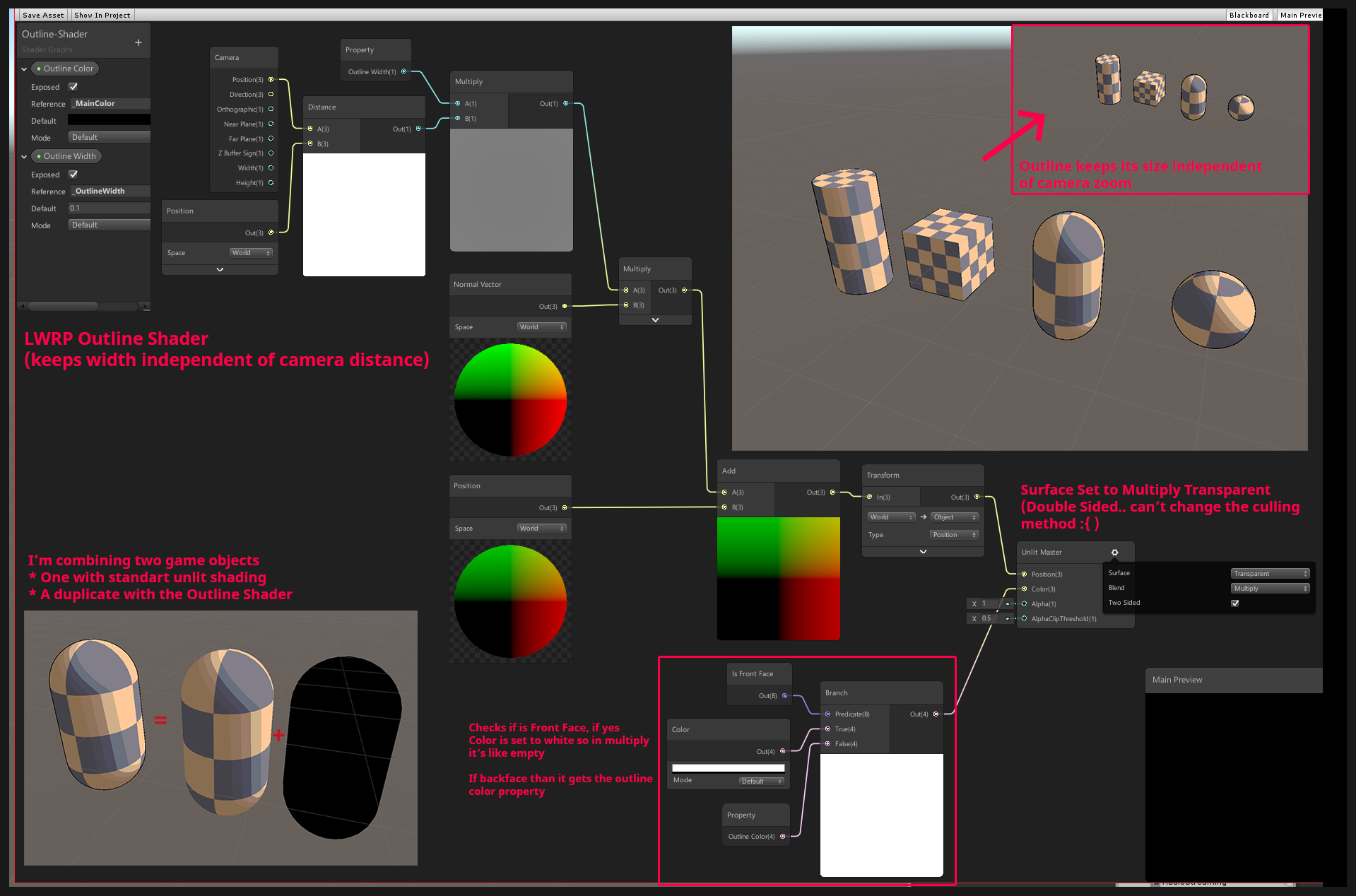
i was trying to outline objects with this. But due to just multiplying the border width would be different which looks a bit strange
@terse nexus I believe object (hull) outline shaders usually use the normal vector to push the vertices out, (Position + Normal Vector * Width). This could be done in World space, then converted to object using the Transform node, (as the master requires the input in object space). It'll only work properly if the mesh has smooth normals though.
Hmm. You'd also need front-face culling though.. and I don't think shadergraph has that option, unless it's been added in URP 7.2.0 which I haven't used yet. Could likely use double-sided and Is Front Face node to alpha clip front faces, but that seems a bit of a hack. Would be easier to edit the generated code and change it to Cull Front rather than Back.
You know...unity just needs an outline option in their standard shaders across all the pipelines. It may not solve every need, but this question comes up like 20 times per week.
And there's several ways. If you "just" want outline, here's one:
https://forum.unity.com/threads/lwrp-outline-shader-help-needed.710642/
But your google-fu should give you 50 more options in short order.
Unity Forum
[IMG]
Hey guys, i posted this on unity3d reddit but got no response yet :( so i'll try it over here. Here is the post:
I'm creating a lwrp shader...
And that one still discusses the same issues as @regal stag just mentioned.
@terse nexus If it's for outline, I'm pretty sure you can convert the normal vector to view space, and from there do some maths to do a constant pixels sized outline
In shadergraph I have some waves by offsetting the vertices, but when I want to modulate the wave height using the scene depth node, the shader refuses to compile...
Is this because frag/vert stages in the shader? And how would I then modulate wave height by depth?
are you in universal or HD?
Universal
I'm not on my PC right now so I'm not sure but when I try mixing scene depth with vertex displacement, I get the error on my master node saying something about 'vs 4.0' or something like that
There's definitely a 4.0 in the error message, I'll check later for full error
It won't even let me connect the scene depth node to the vertex position output, likely due to the vertex/frag stage difference.
Yeah sometimes it does allow me to do it, but most of the times it doesn't
it would only "allow" it if it's in a subgraph, iirc
Yup that's the case
but you shouldn't be able to use that in vertex right now
So how could I modulate wave height with scene depth?
Pre-bake the depth or something?
Is that because sampling depth doesn't work in vertex stage, or just because the node uses a non-lod sample?
Would it be possible to sample the _CameraDepthTexture in the Sample Texture 2D LOD node instead?
you could try, the built in node doesn't use LOD iirc
Just tested, seems to work. 😀
Using this, probably not written perfectly. Used the shadergraph preview ifdef, because I'm also using the Scene Depth node (in the fragment stage) and it was causing a redefinition, but the preview needs it defined otherwise the custom node errors.
(uv is Screen Position node input)
#ifdef SHADERGRAPH_PREVIEW
TEXTURE2D(_CameraDepthTexture);
SAMPLER(sampler_CameraDepthTexture);
#endif

void Test_float(float2 uv, out float Out) {
    Out = LinearEyeDepth(_CameraDepthTexture.SampleLevel(sampler_CameraDepthTexture,uv,0).r, _ZBufferParams);
}```@devout quarry This works 👆 (Could probably just use the Sample Texture 2D LOD node too, although then you'd need a _CameraDepthTexture property and wouldn't be able to use the Scene Depth node as I think there would be redefinition errors then... I used a custom function so I could also use LinearEyeDepth).
Ooh lovely will try this out, thank you
Do you know why using LOD works with vertex stage?
I believe the normal sample method uses screen partial derivatives to determine the mipmap level to use for sampling the texture, which are only available in the fragment stage. For the LOD version you specify the mipmap level - it doesn't need to use those derivatives, so works in the vertex stage.
So what would be the downsides of using the LOD sampling for depth always?
@devout quarry As far as I know the depth texture in URP doesn't have any mipmap levels other than 0 anyway - so I'd assume the output would be identical. Not sure if there's any performance difference between using Sample and SampleLevel though, can't find anything after a quick google.
Alright, thank you Cyan!
@regal stag to my outline issue. I am currently using render features. To re render objects with the extruded (outline) shader and than render the normal object on top. It kinda does what it should.
Is there somewhere any documentation, or info. About how you should upgrade custom written shaders in the Build-in renderer to the new Universal renderer? Or does anyone by any chance know if it is even possible to recreate shaders in URP without using shadergraph
@fossil ermine I'm aware of this video : https://www.youtube.com/watch?v=ErsXwcb3n4c from a Unite talk. It's basically just copying code from the "SimpleLit" shader in the "Universal RP/Shaders" package directory though.

The Universal Render Pipeline brings with it long-awaited accessibility and performance improvements to rendering in Unity.
Speaker:
Yilmaz Kiymaz - InnoGames GmbH
Learn more about the Universal Render Pipeline: https://on.unity.com/2mmIawj
A thanks a lot! I will look to that
@fossil ermine There's also a PBR example shader for URP here, which I just stumbled across. It has some nice comments to explain it : https://gist.github.com/phi-lira/225cd7c5e8545be602dca4eb5ed111ba
Thanks a lot for the help!
Hi im tryin to create a 2D sprite outline shader and it works so far. But the outline is are more inlines ``` _OutlineColor.a *= ceil(color.a);
_OutlineColor.rgb *= color.a;
            _OutlineSize /= 10;
            float up = tex2D(_MainTex, IN.texcoord + float2(0, _OutlineSize+1*_MainTex_TexelSize.y)).a;
            float down = tex2D(_MainTex, IN.texcoord + float2(0, -_OutlineSize+1*_MainTex_TexelSize.y)).a;
            float left = tex2D(_MainTex, IN.texcoord + float2(-_OutlineSize+1*_MainTex_TexelSize.x, 0)).a;
            float right = tex2D(_MainTex, IN.texcoord + float2(_OutlineSize+1*_MainTex_TexelSize.x, 0)).a;

            float outline = (1 - left * up * right * down) * color.a;

            #ifdef UNITY_UI_ALPHACLIP
            clip (color.a - 0.001);
            #endif

            return color + (outline * _OutlineColor) * ceil(_OutlineSize); ```
How to create the outlines on the outside not inside ?
@waxen hollow is this a shader on your mesh?
if so, it makes sense that the lines are 'inlines'
if you want to color lines outside of the mesh
you should do it as a screen-space image effect
it's a sprite
yeah alright sprite
but still the outline material is applied to the sprite
so only pixels that belong to the sprite can be manipulated right?
i don't know
All pixels within the quad of the sprite could be manipulated. The problem here is that the outline (or inline) is based on the alpha channel, which is likely a harsh transition between 0 and 1. It samples 4 neighbouring pixels, and multiplies them together. If any one of those pixels has an alpha value of 0, it results in the inline colour. You'd likely have to change the alpha channel to have that extra padding, if you wanted the outlines to be further out.
Could also try adding the samples together, rather than multiplying. That's what MinionsArt does here : https://www.patreon.com/posts/20894506
If your alpha channel is too close to the edge of the sprite quad though, it will be cut off.
@waxen hollow ^
alright thanks gonna try that
Seems to work, better. Just weird that the outline is brighter. based on what color is when the outline starts
Might need to clamp / saturate the combined alpha value before it's multiplied with the colour
I'm looking for a shader/technique that draw a texture multiple times on the object surface at random position. I feel like it someone already wrote that kind of shader but can't seem to find the right keywords to find it. Any ideas ?
@regal stag i have to idea. How would i do that ?
                float down = tex2D(_MainTex, IN.texcoord + float2(0, -_OutlineSize+1*_MainTex_TexelSize.y)).a;
                float left = tex2D(_MainTex, IN.texcoord + float2(-_OutlineSize+1*_MainTex_TexelSize.x, 0)).a;
                float right = tex2D(_MainTex, IN.texcoord + float2(_OutlineSize+1*_MainTex_TexelSize.x, 0)).a;

                float outline = left + right + up + down;

                #ifdef UNITY_UI_ALPHACLIP
                clip (color.a - 0.001);
                #endif

                outline *= (1-color.a);


return color + (outline * _OutlineColor) * ceil(_OutlineSize); ``` thats my code atm@waxen hollow Try : float outline = saturate(left + right + up + down);
already did nothing changed
Or maybe saturate(outline) on the final line? It was mostly just a guess
k
@waxen hollow I would probably replace the last line with a lerp instead. something like return lerp(color, _OutlineColor, outline); I'm not sure what the ceil(_OutlineSize) part is about, that might be why it's brighter.
ceil rturns the smallest integer value that is greater than or equal to the specified value. Means if _OutlineSize is 0 nothing is applied.
but imma try that with the lerp
I see, but if _OutlineSize is larger than 1, it'll be brighter
awsome 0.0 it works perfect !
lerp(color, _OutlineColor, outline * ceil(_OutlineSize)); still using ceil to turn of outline
thx @regal stag
sadly the drop shadow is full red but thats a propblem for our artist :D
Might have to separate the shadow into a different sprite
^^
How do I enable GPU Instancing on the Sprites-Default shader? I can't seem to find the source on my Assets or Packages list.
I wonder how to get a color value from a texture pixel based on UV
by scriting not Shader graph
@warped field As in shader code? Or in a C# Script?
shader code I just need to read data off a texture file the pixel color of the uv
I tend to use shadergraph, but tex2D (_Texture, uv) should work for Built-in pipeline. (If you are using URP you should use _Texture.Sample(sampler_Texture, uv) instead, although it would also likely be easier just using shadergraph if you are using URP).
For more info, these pages has some example shaders for Built-in pipeline, including some where it samples a texture.
https://docs.unity3d.com/Manual/SL-VertexFragmentShaderExamples.html
https://docs.unity3d.com/Manual/SL-SurfaceShaderExamples.html
Does URP have something similar to tex2Dlod that can be used in a vertex function?
@fleet crown _Texture.SampleLevel(sampler, uv, lod)
(or SAMPLE_TEXTURE2D_LOD(textureName, samplerName, coord2, lod) from the ShaderLibrary, if you include the pipeline.core Common.hlsl. That one handles platform differences but all of them seem to use SampleLevel except GLES2 where it's not supported).
@regal stag Thanks
hey, was wondering if someone could point me in the correct direction for something I'm trying to accomplish.
wanting to simulate a camera where it "exposes" film for a period of time
so I was thinking what I would need to do is do something to add all the rgb values together of each frame the camera sees then clamp to 255 on each pixel's r,g, and b
at first I was messing around with a render texture and writing out the bytes to a series of png files
but that was way too costly and just chugged
so I'm guessing shaders are the way to go so that I can just blend together (add rgb values) of a bunch of frames on top of eachother and save to one final png file?
What is a cutout shader? How does it work compared to other shaders?
Aka alpha clip
alpha clip?
Is there a video or tutorial that will explain how alpha clipping or cutout shaders work?
0 or 1 clip or it doesn't
Like transparency but faster with just 1 level of transparent
Just one level? No inbetween for half transparency?
Idk never used em
Any way to make a shader cut off certain alpha partially? Like making a faded mask?
So that the hole in the image you posted doesn't look as diffused?
got ti working ty
used some cut out today
make this burger a little more glitchy
i think imma redo it again but im lazy
looks like a hologram
thats the plan
Anyone have any issue with emissive particle materials after the 2019.3.1f1 update? My emissive particles are turning fuzzy and strobe like.
Guys does anybody knows how to make text , a transparent mask for layer just below of it like the on in the image
anyone familiar with post processing stack v2 custom effects?
How would I make an object use screen uv instead of local uv
This is my attempt to seamless water plane tiling http://prntscr.com/r31fok
And its not working... :P
I am pretty new to shader graph

@terse nexus You'll want to put the Position into a Split, take the R and B outputs into the X and Y inputs on a Vector2 node and put that into the UV input on the Tiling And Offset node. The offset can then just be the time * speed input. I also have a tutorial/blog post, the first part goes through this, should be of help : https://cyangamedev.wordpress.com/2020/01/28/worldspace-uvs-triplanar-mapping/
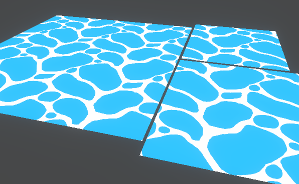
This post includes an introduction to using the Position node to sample textures rather than using mesh UV channels, which is also the basis of Triplanar mapping. It won’t be super in-depth but wil…
still not working :/ Ill look at the tutorial.
This is btw my new and full setup http://prntscr.com/r31t85
The output is fed into the vertex position slot of the master
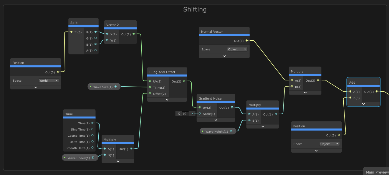
wait just me being stupid and not pressing save asset xD
thanks a lot
How can I transition between two colors depending on an alpha value?
Blending gives weird color tones
Use a Lerp, with the T as the alpha
@terse nexus Blending gives weird color tones
How did you blend?
Are you trying to do some form of transparent blending, or just using alpha to store degree-of-progress between two colors?
@ivory dock Create a material and name it something.
Assign those settings to the standard shader (regular pipeline) or the appropriate shader in SRP.
Those textures are assigned in the "little boxes" beside each attribute. Like the base color texture is assigned to the Albedo, etc. You may not need all of them.
🙂
Materials are settings for shaders. But normally, unless you're writing your own shaders, this isn't the proper forum. The general unity forum, lighting, etc are what you want.
No need, and no problem. 🙂
And now it's gone....... lol
Was too late, the mecanism was On
Guys, I'm very new to shader graph and shaders in general. All I want to do right now is take the Unlit/Transparent shader that comes with HDRP and give it the ability to use Vertex Colours. Right now I can't change the colour or transparency of the image at all. [The image is 2D]
"The Image"? Like you're doing a transfiguration?
@meager pelican that's the default material for unlit/transparent and see it takes in an image
the image is basically a dot that fades out, it will be a ripple but I'll need vertex colours
Yeah, that's the albedo texture.
OK, so use SG, and there's a vertex color node.
https://docs.unity3d.com/Packages/com.unity.shadergraph@6.9/manual/Vertex-Color-Node.html
multiply that times the texture's uv result.
So
A texture-read node * vertex color node. Both can/will give you a vert4 (RGBA) with alpha, and you'll have to make sure you do transparency.
Okay I do see what you mean, but when I create a new unlit shader graph this is all that appears
Like I said I have 0 experience with these, I'm sure it's super easy - I'm guessing I need to add an albedo texture
well I added a texture2DAsset so then I can drag my asset in there which is fine
Yeah, rather than publishing a pic, I'll just describe it so you get the details. (I hope, from memory and off the top of my head).
Click the + on the RippleGraph "blackboard" on the left, add a texture node, name it something, and make sure it is "Exposed".
Then add a vertex color node by right clicking on the black background and selecting "add node" and finding vertex color.
You need to read that texture at the right place for the pixel you're drawing. That's done with a Sample Texture node. So add one of those.
okay
It will automatically use "uv0" as the input, so you should be OK.
yeah it does
OK, so now add a multiply node
You'll have to tell the texture node what texture to read so connect that up.
yeah done
OK, so multiply the output of the sample texture node and the output of your vertex color node.
Two in, one result out.
done
Now test it out by plugging that result into the color node. You'll need alpha too. So you can take that result and plug it into a "split" node. Then take the result of the split node and put it on the alpha input of the unlit master node.
So you'll have two lines out of the multiply...one to the color, one to a split and the split's alpha to alpha.
I did that?
OK, that will work. I think. Did you assign a texture to the texture input on the sample-texture node?
Just did now
You'll need to adjust the alph-clip threshold too.
Don't forget to save it or it won't work. There's a button...
okay thanks I'll test it a bit and see
You'll also need to click the cog on the Master node and set the surface type to Transparent, if you haven't already.
hmm it seems to no longer be transparent, well part of it is (the outside of the circle) but the inside seems to be one block colour
"Block color"? Did you texture show up in the preview?
Also like I and Cyan said, make sure the master node is set to "transparent".
You have to assign a texture of some sort. Does it look like a white circle or what? (your texture that you want to use)
Yeah kind of here I'll show you
As you can see, the ripple texture is basically a white blob but it has slightly transparent parts. And even so, nothing is showing in the preview at all
I was wrong
it's 2D so I had to rotate the preview around
But all the preview is, is a white circle
The higher the alpha clipping, the smaller the circle, so I guess it does realise that the alpha is lower as it get''s further out
Yeah. The preview is a white circle because your input texture is a circle, right? Anyway, how are the vertex colors assigned on your mesh? (Are you using a quad or what?).
You'll probably want to make a material, assign this shader to it, and see how it looks in unity.
I did, it's a white circle lmao
OK, well, are your vertex colors white on the mesh that you made?
Yeah I believe so
I think I got it
I set the vertex colour to a very transparent colour, and then the clipping very low
And was it mostly-transparent?
Yeah
Exactly what you asked for. Maybe, or maybe not, what you wanted. 😉
If you just want to modify the transparency, you don't need to use vertex colors to do that.
I don't?
you can just use a slider 😛
Nope. ;)
You can just "expose" a float on the blackboard and plug it straight into the alpha value of the result mater node.
Oh damn okay, well I have it now xD
Is vertex colours just for changing the overall colour then?
Yeah, it's another way to assign colors on a mesh, storing the info into the mesh data.
It gets "interpolated" across triangles too. So you can get some cool color effects if you want them.
Oh I see okay, I really need to find a set of videos going over shader graph because it seems amazing, I'm planning on using it to simulate wet ground/puddles too once I figure out how
bro i got a vid sec

I like to make videos, i would like to see out there. But there is no video out there yet, that gives a brief overview over ALL shader graph nodes and how to use them. This is the tl:dl episode for everyone who's got their first tutorial behind them and have already set up the...
baaaaaammmmm
all ze nodes
It's alright for showing you which nodes are available, but I feel that video doesn't really explain the nodes in any detail. But you can also right-click a node to view it's documentation though.
I just need to learn the basics so that I can apply them in different ways. I was thinking about learning how to do snow and how to do rust, and then maybe from there I can make puddles? So they only go on the top of surfaces and they have more/less reflective parts or something
sure I mean Im kinda sad its not like shaderforge where you can get all the light information and write your own lighting model
do specular reflections use the dot product and normals n shit
half lambert from valve is what got me into shaders long long ago
welp I've got a long way to go sadly
There are several online courses you can take, some for like 20 bucks....but the ones I'm thinking of aren't shader graph specific. There's one or more for unity's standard pipline though. And some using threejs and other things.
You have "programmer" in your profile, so I assume you can type code as well as drag connectors around (joking) so you could get a good overview of GPU's and how they work, as well as some basic math and lighting info.
Yeah I'm sure I can learn to write them with code but I feel like over time that's going to become obsolete in tutorials for new things etc since everyone seems to use the graph view now
Sure. And JAVA and object oriented code is the future! ;)
SG will never be "everything" to everyone. It's just one tool. IMHO. And it's a fine tool. And you can start there. But it won't teach you about the GPU hardware or the pipeline in and of itself.
And "graphics programming" is really a discipline in itself. Oy.
Hey all, had a question on performance. I'm discarding certain vertices in a compute shader by setting the position to 0. Is there a performance overhead on like Android devices for doing so?
If it's a compute shader, why would there be a diff? And what verts are you processing in compute shaders?
If you're doing a pixel shader discard in the regular pipeline, it can make a diff on some mobile systems.
Hey all, had a question on performance. I'm discarding certain vertices in a compute shader by setting the position to 0. Is there a performance overhead on like Android devices for doing so?
@crystal patrol
There seems to be a massive frame rate drop so just eliminating what might be causing it. Must be another part of the shader. Thanks @meager pelican
Nah. Setting position to 0 of a vertex in a structured buffer so that the pixel shader will discard it instead of using discard
That's a new one, can you elaborate? Position 0 would be the object origin....so you mean that the frustum clipping would skip it if you never look at 0,0,0???
Oh, relative pos of the vertex and the mesh location. Got ya. Slow today. I suppose it would collapse them down to nothing, basically.
If you're updating a structured buffer, I don't see why that would harm anything. Certainly wouldn't map to many/any pixels that way.
Do you need a special "mesh"...so you don't generate triangle strips, right? You generate polys out of the SB and generate tris with 3 points each or with 0's....yes?
One thing you can do is see if geometry shaders are supported since you have compute shaders. And then don't generate the tris that you're discarding. IDK about net savings though, GS has overhead too.
Yeah not going to add a geom shader. It's definitely not causing an overhead, isolated and checked. But thanks anyway
Yeah, of course, if it's not causing overhead, no need to add the GS....if you could skip the whole compute pass, then maybe.
When I use this method to draw a FoV for my AI I get some TV fuzz triangle... :/
Nvm, just had to increase the detection margin
why do soft particles work when i play in the editor but not when i build the project?
there's no way to get SV_VertexID in shader graph? 👎
Does anyone have a good strategy for rendering a World Space canvas on top of everything in the world in HDRP?
hello, does anyone know how to bake and process AnimationCurves on the GPU? Currently i have a system which samples quite a lot of data on the CPU and sends it to the GPU. The overhead from the CPU takes about 0.4ms to prepare the data per GameObject, most of which is the result of needing to calculate and set GPU variables.
Textures maybe ? Also Data buffers ?
that still leaves the question of sampling. VFX graph is able to do it, but i've tried searching the code and wasn't able to pinpoint how exactly they're baking the data and then sampling it on the GPU's end.
@naive mural I found this
https://github.com/Unity-Technologies/ScriptableRenderPipeline/blob/773dee9a44ff68bca8b994a2a26ce0c76adc79aa/com.unity.render-pipelines.core/Runtime/Utilities/TextureCurve.cs
GitHub
Scriptable Render Pipeline. Contribute to Unity-Technologies/ScriptableRenderPipeline development by creating an account on GitHub.
Though, it doesn't look like it's used by VFX Graph
@low lichen thanks
Basically, plot the curve data in a texture, with a fixed time step, and sample in with a regular texture sample. Bonus : profit from the linear interpolation
How inefficient is making outline by creating 8 copies of the sprite? Should I just do the outline in a PNG itself?
I don't do 2d but I do know there are sprite shaders that allow effects, I'm almost certain it's more optimized than using that many sprite duplicates
png outline could work if it's pixel art, but if you want a smooth outline (higher res sprite) you want a shader I think for sure
@grand jolt https://www.youtube.com/watch?v=FvQFhkS90nI

✅ Get the Project files and Utilities at https://unitycodemonkey.com/video.php?v=FvQFhkS90nI
Let's make a Outline Effect Shader to apply to our Sprites in Shader Graph!
Check out the entire Shader Graph Tutorials Playlist
https://www.youtube.com/playlist?list=PLzDRvYVwl53tpvp...
Could I take a realistic character and make a shader to make them look cartoony?
experimenting 2 hours, anyone has an idea how i keep the faces connected?
https://cdn.discordapp.com/attachments/294789611052597248/679057117109288961/unknown.png

@plain pumice they're splitting apart since they aren't actually welded together (if they shared vertices, the mesh would have smooth shading). If you want to apply a vertex push effect to a mesh with flat shading, you can use a derivative method seen in post #2 here: https://forum.unity.com/threads/geometry-shader-flat-shading-in-shader-graph.718415/
Unity Forum
I'm using LWRP in my project and I would like to implement a flat shading for my graph shader using a geometry shader described in this tutorial. Is...
i need a shader that can open a book any help
@orchid peak sure you tagged the right person? I havent talked in this discord for months
not cause this discord isn't cool, but because I can't bother you guys for code advice until I get my life together
got it one minute ago, the shader was fine, the mash had no smoothing....
thanks for the link anyways ill look into that
Made a PBR shader, whilst messing around I've managed to leave a texture 2D in there that's greyed out. I 100% have not, there are no unused texture 2Ds in the graph. Its really bizarre. Annoyingly it affects my roughness, this old tile normal even though it's not plugged in
@shell walrus
this could be a texture2D that is defined inside of the graph
not as a property
like this
Hi Everyone ! I need your help. I'm trying to mix multiple normal map (4 normals) to create something like the layered lit (only with shader graph in nodal system). The fact is Each normal need to pass though a mask, How Can I do this ?
I try to pass each normal through it's own mask then normal reconstruct it one by one then normal blend Normal 1 with normal 2 and normal blend normal 3 with normal 4 then normal blend (N1+N2) with (N3+N4) but it's look like it doesn't work. the result look like really flat

(In the picture, the A input of each multiply is a differente normal map and each B input is a differente mask