#archived-shaders
1 messages · Page 135 of 1
Yes yes but yay for nodes 🙂
To each their own. 🙂
lol
@leaden gyro have you noticed any performance issues when working with larger graphs?
Especially when adding properties
Not yet
but I know that is a thing
But the technology will develop, especially since its so new in Unity
I experience it all the time, very very very frustrating and killing my workflow
Well there is lag when making properties, yes
but thats just unity being stupid
theyll fix that sometime soon i guess
yeah but I'm speaking about 3-5 second hangs
same when renaming properties, renaming references, changing nodes etc
Hahah only a few months ago the whole window would crash if you changed a property name
and I'm always on the latest SG version, always hoping for improvements, but nothing yet
But yeah itll pass once Unity gets this buggy mess under control. Its pretty fair, since its such a new system
Unreal has had so many years to optimize it
Its a wonder it works so well in Unity
Idk, it's almost 2 years since release
with the different render pipelines, everything is a mess right now. I guess we gotta be patient
I'm not sure if this is better asked somewhere else but it's shader-related so here goes
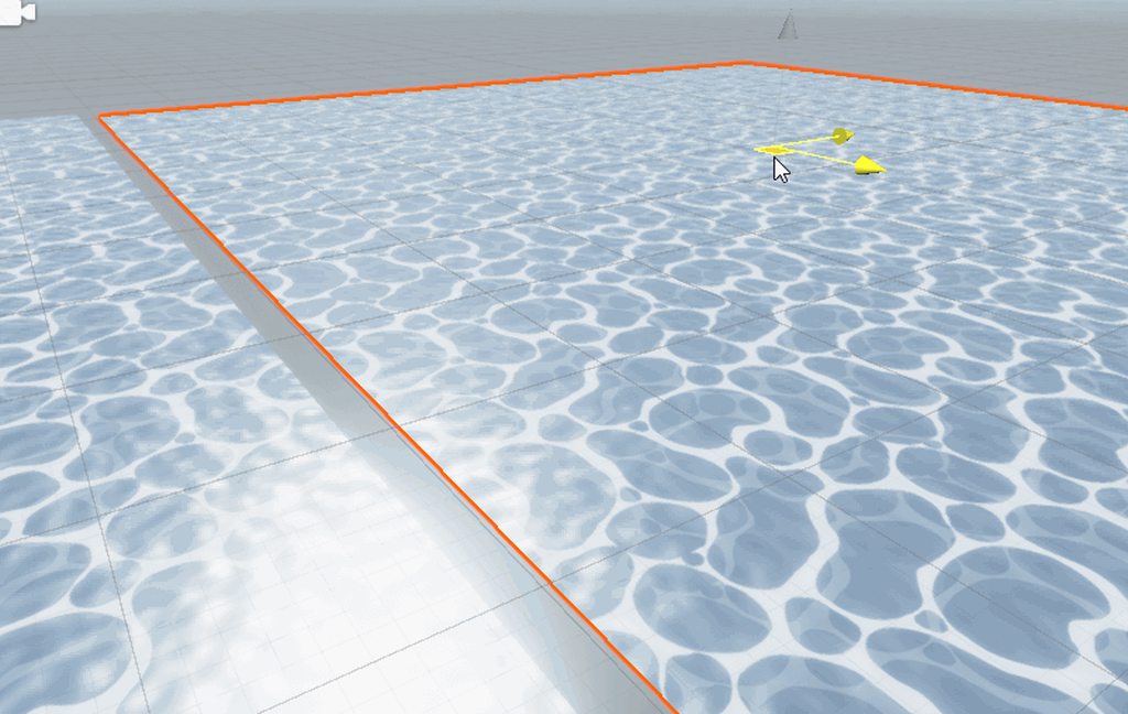
Has anyone here worked with Gerstner waves?
I'm using 3 waves here, but I'm still getting a hard time getting it to look right. It looks good to me, but it's still super easy to pick up a pattern. What techniques could I use to make it a bit more 'random'?
I'd love to hear some techniques of people that have used these
that's about as far as I got with it myself
I never got it look like real ocean but didn't spend much time tweaking it
I read some guy's master thesis
and his solution to get rid of the patterns is applying noise
which I'll try I think
I'll also do some depth-based attenuation, that might get rid of some repetition
@fervent tinsel you did this in shadergraph right? What was your setup like? Just 1 custom function node? 1 custom function node per wave?
it's been a long time already, I think I did all the math in nodes 😄
same haha, just 1 big node outputting vertex pos/normals
if I remember right, I ported the graphs from some ue4 tutorial
ue4 materials are all nodes
or using those old catlikecoding tutorials
there are some neato gdc talks about ocean rendering if one wants to dig further into this topic
so I've been trying to get this project from worldspace working as @leaden gyro tried to explain, but uhh
in the preview it looks fine
but in the editor it stretches
almost as if it projects from an angle?
I could almost rotate it and use it as a waterfall now lol
I'm kind of lost, do you mean like this?
What you had before, but B going into the Y input rather than G
The split node uses RGBA, but it can also be interpreted as XYZW, so G=Y, B=Z
I should've said R and B instead of X and Z, my bad for confusion
oh yeah, I see
sorry for asking so much stuff on here by the way, I swear I'm trying my hardest to figure stuff out myself first haha
it's kind of working now?
it's still not entirely working the way I intend, but I think that's because I'm plugging this into the wrong nodes
but the texture is not longer stretched?
should not be stretched if tiling.x = tiling.y
it's not stretched anymore, no! thank you
I'm just trying to make sense of where to actually plug in the world space now
So you've taken the R/B (or X/Z) components of the world space position, and now you can use that vector2 as your UVs
so for example in a sample texture2D node, if you want the texture to be sampled using world space UVs, you would use those
yeah, I thought I had it by plugging it into the two first offset and tiling nodes that I use
and it sort of works? but not quite
it looks fine I think, you put it in a tiling and offset node, and then in the UVs of the noise
let me see if I can make a gif of this and keep it under 8mb lol
mp4 would result in smaller size I think
don't ask me why the video exporting upside down, I have literally no idea lol
aw, discord doesn't embed avi?
hold on
Hmm, if you're using world space uvs it should line up, that's one of the advantages of using it
Is this in URP or HDRP btw?
LWRP
Ah okay
I guess that's the new URP now, no?
URP is the new LWRP
right
Yeah LWRP is the older versions
but that shouldn't be much of a problem, right? I'm on 2019.2
I'm not assuming it's an unity bug at least
I'm probably just plugging in the world space projection into the wrong nodes if I had to guess
Can you try a simpler setup with a single texture sample and no scrolling, see if that lines up?
I think your issue is you are modifying the world space UVs (tiling them) then using them
and so you are working with 2 sets of world space UVs?
Looking at the video actually, you might be using worldspace UVs for the darker foam, but not for the white foam
this is how I'm using it
the top one are the normals, the bottom one are the ripples
Yeah that tiling and offset node at the bottom doesn't have a UV input
So it's using the plane's UV0 channel instead
I was assuming it would work like this
That's also a lot of tiling and offset nodes, you probably don't need that many
you're probably right yeah
I got it though, it's working now
hm
this is what I did?
I removed that topmost tiling and offset one as well as it was indeed redundant
You now seem to be offsetting the (worldspace) UVs by itself
how would you suggest to do it?
Disconnect the two nodes from these offset inputs
you mean like this, yeah?
Uh no, I meant leave the UV input, but disconnect the "Offset" ones
If the bottom one always has a tiling of 1,1 you could remove that node entirely too
ah alright, I understand now
thank you
I set it up like you said and this works just as well
I'm assuming having less nodes also just saves on performance, mhm?
For inside the shadergraph editor, yes. For the final shader when rendering, I doubt more tiling and offset nodes will make much of a difference. It does "Out = UV * Tiling + Offset"
right
I guess having less operations is better though
now I got my world tiling, I guess I can try foam around edges
how do I make those node groups? if they're called that
I tried googling it but couldn't find it
I think it might only be in URP, but drag a selection, right-click and there's a "Group Selection"
The LWRP might be too old to have groups, can't remember when they were added
strange bug?
I don't really know how tessellation works but I am guessing it may work under the context following: is it possible to have two shaders on one object. One of them a regular tessellation shader, and one a shader graph shader that displaces the mesh. Would they work together?
@hearty wasp Awesome to see you got it working :D
When you guys were talking I was asleep, it was 12-2 in the night here
could someone help me with making an outline for sprites
@leaden gyro its alright, and thanks for all the help to you and @devout quarry and @regal stag as well! Definitely inspired me greatly to continue with shaders
@hearty wasp definitely my favorite part of Game Design
lol my outline is broken, rather than apply outside the character its applying inside
so it has the black line surrounding the actual sprite
The easiest way to this is like this:
Take the sprite into a sample texture 2d
Take another sprite into a sample texture 2d
Change the scale via the UVs of the second sample
Now you have two different sized sprites
Use the second spirte as a mask so you can overlay another color on top of it
And use the bigger sprite as alpha value
I hope im making sense here, let me see if I can do this myself in a shader
the resize however for some reason still has the pivot on the bottom left
all the tutorials ive seen offset them a bit up down right and left
but that seems like a bit too much effort, especially once you are adding more and more sprites
also it's a bit "squarey" if you know what i mean
Okay
Then make the second sprite as an ew texture in photoshop
*new texture
just use a smaller brush
make sure youre properly in the center
and tada you have one smaller particle
my sprite is 8x8 already though
the outline thickness would be 25% of sprite's size
hm, well I guess the only option left is resize it and add them manually
There we go :p
Make sure you set the shader to Transparent and Alpha mode
You can do that in the master node settings
Ignore those red and green channels, Im recycling a texture I happened to have in my project
I just want to get something like this from this
Ohhhhhh
but this one is resized, which I'm trying to avoid
because then I'll have to scale everything accordingly so its proportional
Hmmmm
Then I have no clue, I dont work with pixelart kinda things... if you find a solution though, id love to learn from it 🙂
oh
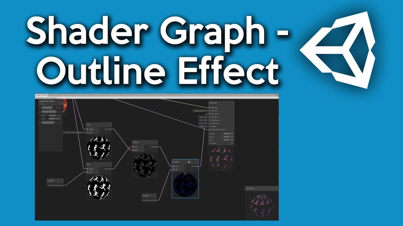
Help to support the channel if you are feeling super kind: https://www.patreon.com/dapperdino
Join our Discord: https://discord.gg/sn9xXK4
In this video I show you how to create a simple outline shader for sprites and a simple one for cubes. I will create a 3D outline effec...
I think that might prove useful. Something in the direction of using a Step node and overlaying that over the texture
I've tried following it but it was a little bricky
bricky?
sec
Im guessing the proper way to get this effect is to make a custom render pipeline feature which takes objects of a certain tag and then projects a outline aroundthose objects
but I have no clue as to how youd go about that
if im using this 4 offsets method then it becomes like this rather than this
https://alexanderameye.github.io/outlineshader.html @leaden gyro
@devout quarry hwo do i access that

lol, that outline is more suitable for 3d projecs i think
i literally want just line on the perimeter
oh well, I think I'll just go with outlining them manually, feelsbadman
I was just going to say, why can't you just build the outlines into the spritebook versions? Would be faster too. And they'd look the way you want them to.
This kind of stuff is why there's such a high ratio of artists to programmers.
then its going to take up more memory
ah screw it, ima do that instead
too much effort to add outline shaders
oh wiat, but then i wont be able to adjust thickness
AAAAAAAAAAAA
You want adjustable thickness too? For 2D sprites?
Is this a special effect that gets turned on and off? Or just "contract coloring" for the sprites?
If want outline in your corners cant you just modify the sprite shader, and make it draw a fatter copy with a fill color behind your textured sprite?
Yeah if your always going to have it on, you should just generate the outline with a tool - there is some available
I want to always have it on but with adjustable thickness/color
The only solution I've came up with is 8 offset copies
But that doesn't seem efficient
well actually not always on, toggle-able
Well then it's easy. Think color replacement instead. If you want it thinner, just use transparent on one set. It's pixel-art, right? So pixelated.
Yea, most sprites resolution are 8x8, up to 16x16
Use special colors for the outlines. But are you actually using those low-res textured? Or is that logical resolution?
I don't quite understand
The PNG image resolution is 8x8
But in game it's scaled up obviously
What's the color depth?
Do you want the outlines (at widest) to be beyond the 8x8 or 16x16 area? AKA it adds extra?
yes, so its the same as in the example above
https://media.discordapp.net/attachments/497874081329184799/670996051561414672/unknown.png

Yeah, but that looks the same width and height, but with an outline, right?
no, its bigger. the first one is 50x50, the other is 48x48 (resized x3 so i could draw the line manually)
Hmm.
OK, so you can select your sizes , and 50x50 works for you, instead of 48x48.
I mean, the sprite was originally 16x16
I know, but I'm talking about selectively replacing the outline. I guess it doesn't matter too much, if you want to intrude INTO the sprite with the outline.
But OK, what was the color depth? How are you doing the colors as far as the real storage, even if you only have 256 values used?
AKA what texture format?
You can see in the inspector.
What I'm about to discuss is that you build the outline, or outlineS into the sprite, but just don't display it if you don't want it there. ;)
It's the opposite of what you've been thinking...selective un-outline. You'd do that by selective color replacement or clipping. You'd have some value be "the outline" color or colors. Maybe you have two or three special colors as it gets thicker. Thickness types 3,2,1, 0 with 0 = no outline. And then you could swap in your variable outline color too. You'd build that into the sprite data.
And by "colors" I mean color values in the sprite data, not what is displayed (which could all be the same color).
Hmm
So basically, you construct the sprite like the fig on the left, and then the shader optionally makes it look like the one on the right, by not drawing that black outline that is a special-flagged-valued color. Or alpha. Or something.
Just a thought. And like I said, you can use several values for several thicknesses. 3,2,1 in my example.
@hearty wasp Just wanted to show what kind of distortion you can achieve with a few sine functions.
and it's really just 1 node you need, sure it uses a custom function but if you are somewhat familiar with some basic coding it will make sense
@meager pelican isn't it basically the same as replacing the sprite with the one that has an outline? Or does it add the outline
@devout quarry Nice, put the sine functions into scale aswell
It subtracts the outline.
But you'd only need one sprite.
But sure, if you want to have 4 sprites, 0, 1, 2, and 3 pixel-thick outlines, and use a flipbook type of thing, fine too.
I guess the approach here is to put the outline mostly in the artist's control for what it looks like. Build the data into the sprite and then the shader can operate on it, rather than having it try to deduce what you would like to see.
Oh so the outline is built in but the shader 'cuts' it a bit
But what if I wanted to add the fadeaway glow on top of that
Kind of gradient-like
Right!
And how much gets cut depends on the values passed. And color could be substituted, for variable outline colors.
So if you use, say, alpha (not really recommended) as a "flag", alpha 255 (1.0f) is normal sprite stuff, alpha 0 is transparent, alpha 1 is farthest/thickest outline, alpha 2 is nearer, alpha 3 is right up-next.
Glow? Fade? New.
Is the shadow/glow all the same color? Maybe alpha faded. So in this case, black, with variable fade.
Does it change with outline thickness?
Adjustable color. (Hex value entered by player)
Yeah, but all the same for all pixels, right? Not counting alpha fade.
OK, How many colors in a sprite?
Not counting outline and shadow/glow.
Are you emulating a 256 color scheme or something?
@regal stag Hi there, always enjoy following your tutorials. Big thanks for helping me learn a bunch of stuff! I was following your fog shadergraph post and I can't seem to get it working.
that's the graph. alpha clip is zero. all the nodes are attached as your post instructs afaik
Settings are set to depth texture enabled, i'm in Unity 2019.3.0f3 with SG 7.1.8
@meager pelican there are hundreds of different sprites, each has different color theme
@tight forge What's the Fog Colour's alpha set to? (In both shadergraph blackboard and material inspector). Shadergraph defaults colours to 0,0,0,0, which can be annoying. It needs a higher alpha value otherwise it'll be fully invisible, unless you disconnect the Multiply with the Fog Colour alpha in the graph.
thanks for replying! ah well that's the thing it was set to zero by default, and then I realised if i play with the alpha slider in inspector, something actually happens.
but the plane just looks like it's faded out, there's no 'depth' to the fog as your captures show
@grand jolt OK, but are they all from some palette? Or are they full RGBA values?
So just off the top of my head:
Color (0,0,0, non-zero & non-one) is transparent glow swapping glow color RGB values in.
Color (x,x,x, 1/255f) is the first outline level, swap outline color
Color (x,x,x, 2/255f) is the next thickness of outline
Color(x,x,x,3/255f)....
Color (r,g,b,1f) is the sprite "dot's" color.
@tight forge The "depth/density" of the fog can be controlled by scaling the plane in the Y direction. It's a result of using the transform to object space.
Pretty sure it's rgba, I'm using asperite if it changes anything
@tight forge No problem. And, you aren't an idiot. Perhaps my post isn't entirely clear about the scaling.
Much appreciated, your twitter video does show the scaling, i just missed that because clearly i haven't had enough coffee yet.
In SG, what does this mode mean?
I found that it changes what pixel is read when I leave the texture slot blank
but what else would this affect?
And which one should I choose
I believe it is just the default value for the texture
Like as you said, when the texture slot is blank
Allright! Makes sense for me to have it black by default so I wonder why the default is white
If I leave the slot empty, I think you would like to have nothing show up
Hmm, I guess. I usually just leave it as white. I don't tend to not have a texture there. I guess if your texture is a mask for another texture you might want it to default to white for "no mask".
The color is (0,0,0,0), so if the shader uses this alpha for transparency, it won't show anything.
@devout quarry It's the same as when defining a texture property in code btw, like :
_Texture ("Texture", 2D) = "white" {}
For 2D Textures, the default value is either an empty string, or one of the built-in default Textures: “white” (RGBA: 1,1,1,1), “black” (RGBA: 0,0,0,0), “gray” (RGBA: 0.5,0.5,0.5,0.5), “bump” (RGBA: 0.5,0.5,1,0.5) or “red” (RGBA: 1,0,0,0). (from https://docs.unity3d.com/Manual/SL-Properties.html )

okay cool thank you
Hi!
I decided to learn the Unity shader graph. I've been trying it in both LWRP and HDRP. So I followed some instructions on how to make a dissolve shader. After making it in LWRP it worked fine (see screenshot link 1). But the same effect acts very differently and weird in HDRP (see screenshot link 2). Is there a workaround or am I not taking something into consideration here? (The HDRP shader graph is using HDRP lit shader as base. Tried using the LWRP pbr graph but the preview failed to work)
Screenshot 1 (LWRP result) https://gyazo.com/04fa63a63e95a0b90b85df8a1e23ed11
Screenshot 2 (HDRP result) https://gyazo.com/f3ff7268c735e6a46b523228355e4097
Screenshot 3 (LWRP shader graph following brackeys tutorial) https://gyazo.com/c364fe260b79b0da281cd2db04d1f733
Screenshot 4 (HDRP shader graph) https://gyazo.com/7246c9c35cbedc603c92fed5da6ab2c2
Note: Using Unity version 2019.2.19f1 for HDRP and 2019.2.17f1 for LWRP


I suspect this is a bug and unavoidable right now...
Edit: I disconnected and removed the emission effect to make the issue easier to spot, in case that seemed confusing to look at :P
Line renderers are infuriating me. I've got a fancy pants shader to light my line renders, only to be foiled because they are oriented to face the camera direction, not the camera position
how can i get the reverse of the fresnel effect?
@brazen kernel In Shader Graph or in code?
use '1 minus'
if you multiply by -1, the black parts that are 'zero' will still be zero
so you won't get the desired effect
but if you use the 'one minus' node, 1 will be come '1-1 = 0' and 0 will become '1-0' = 1

Is there any way to put emission in 2d shadergraphs?
I seriously can't remember how to make a seed work with the shader graph gradient noise node. What's the node setup again?
@distant pawn seed? Are you referring to the Random Range node not gradient noise?
no. With the gradient noise, I seem to remember there was an arrangement of nodes that ported into the UV input that allowed you to pick were on the Gradient noise you started (a seed) via a Vector2.
Ah okay. You can offset the UVs with a Vector2 to obtain a different section of the Gradient Noise. The Tiling & Offset node can help with that (or just an Add/Subtract).
So, I'm doing some shader stuff with line renderers, and as far as I can tell the normal vectors they are generating are completely wrong.
@sand wasp I take it you have the "Generate Lighting Data" enabled on the LineRenderer?
I do
I don't know what it is with line renders, the way they align with the camera is just... kinda funky. Like, you keep the camera in one place and rotate it and they ever so slightly twist
I hate these things, the documentation says they try to face the camera, but it's like a combination between trying to face the camera and trying to face the camera direction. Unlike particle systems they don't have a bucket of different render alignment settings.
Can definitely see what you mean. The generated normals look more like an average of the view direction more than actual normals
you can calculate normals either by using a geometry shader or by using ddx/ddy in the fragment shader
in both cases you need a cross product
and the world/object position of 3 point on your surface
ddx/ddy?
is there a way to share a gradient noise texture (that is generated by the Gradient Noise node in shader graph) with a script?
or any other way to sync up Unity's Mathf.PerlinNoise and the Gradient noise node. Gradient textures don't work due to them not syncing up for some reason
It depends on what EXACTLY you want. Unity's gradient is pretty diverse with lots of points for evaluation and abrupt changes.
What I usually do is use Unity's gradient color tool, and decide on a "resolution"...such as 1024 steps. Then I create a 1024x1 texture, and fill it in with the gradient results by evaluating the gradient with a for loop and setting the texture accordingly.
Then set it in the shader(s) and then just use a texture sampler to sample it with a "UV" of x = point, y=0.
Noise is the same thing, but 2D. So evaluate it and generate a texture. Don't use the "math" based ones in SG. Generate one yourself, and it will "sync up".
Basically, drive it all from C# and just sample. Auto-sync.
They even give you some sample code here if you want:
https://docs.unity3d.com/Packages/com.unity.shadergraph@7.1/manual/Gradient-Noise-Node.html
You could use that and convert it to c# if you wanted. Or just use what's on C# side and make your textures. I suppose the sampler could skew the results slightly depending on settings. So you may have to play with lerping in C# to get it close. Or do your own node and do the same equivalent code on each side.
Basically, I'm saying you're going to need one authoritative side. Or some very careful custom code on both sides that produces the same result.
@sand wasp Basically what it does is it gives you the derivative of a specific attribute in the fragment shader (for example world position) to the current fragment's neighbouring pixels. So by taking the derivative of the position in x and y direction you could calculate the cross product between them to get the normal of your surface
http://www.aclockworkberry.com/shader-derivative-functions/ is a pretty good resource

In this article about shader derivative functions I will explain what they do and why they are so important. I’ll give you some details about hardware implementation and I’ll show some …
I'm no stranger to dirivatives, I'm calculating normals in tangent space via shadergraph in this example
but tangent space seems to be funky with line renderers
Hi, buddies, I just wrote a tutorial about creating marble shader in Unity, have a look if you are interested: https://twitter.com/knh1901/status/1221703373415563264 Thanks for feedback! :)
Hello, I have created this tutorial about creating ray traced marble shader in Unity. It got longer than I previously expected. Have a look! https://t.co/DFMTQTldH8
#madewithunity #gamedev #graphics #shader

@high scarab You can display it in the Showcase channel #archived-resources
Thank you :)
So the new PBR master node has 3 new values, Vertex Position, Vertex Normal, Vertex Tangent. Since I move my object with the Transform Node, should I connect this node to all the 3 above or the Vertex Position only?
Using the transform node you should transform to object space
And put it in the vertex position slot
that's if you're only moving the object
if you have your own normals you want to use, also transform them to object space but set the transform node to 'direction' instead of 'position', then plug it into vertex normals
For example like this
The custom function node gives me an offset and some normals
normals are transformed to object space, using direction type, and put into vertex normals
position is transformed into object space, using position type, and put into vertex position
Oh my god you are amazing @devout quarry
Well I am using the normal quad so I don’t think I have my “own” normals correct?
So it is safe to just plug it into Vertex Position and leave the rest?
Yeah should be
Thank you very much!
It's only if you're moving the vertices in a shape like a wave or something that you would be changing the normals
Since lighting has to behave differently
I am kind of scaling them
Like from 0 to 1
And normal move with Lerp from one pos to another
Also @devout quarry any idea why the new gradient doesn’t have a middle slider? Like it has 2 only
It used to be 3
New gradient?
The gradient variable I mean
In the blackboard where you add your variables
You can add a gradient
Hello , How can I apply gaussian blur to a texture 2d? Is it possible?
hey there I'm trying to use the Fog node in shadergraph but with a unlit master node. While the unlite master is active density always returns 0. If i set a PBR master to be active then the density returns correct values. Anyway to get it working with a unlit master node ?
Hi, can anyone help me with displaying my camera depth texture (so I can see it with my own eyes on the screen)? I tried the following
- Create a second camera that outputs to a render texture, but I can't seem to control that it outputs the depth texture
- Create an unlit shader graph with a Texture 2D node that references _CameraDepthTexture -> Sample Texture 2d -> Albedo on my master node and then assign that to a material -> plane
Oh I also tried without 2 and simply changing it to a Transparent graph and set the AlphaClipThreshold to 0
Do you want to do it by writing the shader for it yourself or do you want to use shadergraph?
Shader Graph (or if it's possible to simply have a camera display it on a render texture)
It's not really for anything practical other than being able to visualize a depth texture while learning about these things
I basically just want to see this
are you using hdrp, urp or the legacy pipeline?
URP
okay give me a sec i have to check the draw calls in urp cause my project is hdrp
my camera is orthographic, if that matters
I know it would matter if I wanted to use the Scene Depth node to do stuff, but not sure it matters if I simply want to view the camera depth texture with my own eyes 😄
slowly working my way to understanding how to use scene depth in a shader to do things like fog or water color based on depth
Alright so here's what you have to do
make sure depth is enabled in the settings of your urp asset
Open the frame debugger afterwards, select the depth prepass group and if you want the result to be greyscaled instead of red you have to select channels R instead of All
The result should look like this (or red if the channel is not set up properly)
and the frame debugger is available in the scrub version of Unity? 🙂
Sure, basically everything is except dark mode and some Unity services
dark mode.. I'd pay $50 just to get that 😉
I run everything with dark more, except unity .. gnahh 😄
@neon gull hmm so it's all red.. but I'm sure it's enabled
can you send an image?
I mean an image of the result (the red one) 🙂
and I'm using the high quality setting
if I change my camera from Ortographic to Perspective, it turns completely black instead 😄
okay, it might just be because of the far plane distance, you can either try lowering that one (i think it's 1000 per default) or you can try this slider up here to change the range
in my scene I have a plane (as a background) with simple gradient shader
that plane has the same distance to the camera for every pixel, thus the depth texture has the same color everywhere
The reason it is red is because depth uses only one texture channel (in this case the red one)
if there are no objects with another depth than your plane you won't see a lot of stuff
it's a solid red
It's not
see the screenshot above
"okay, it might just be because of the far plane distance, you can either try lowering that one (i think it's 1000 per default) or you can try this slider up here to change the range"
oh you're right
just try this and you should be fine
If you want to convert it to black-and-white though, which should make it more visible, you can do that using a screen space shader
I did try changing that level but it had no effect
and sample the red channel of the _CameraDepthTexture
try changing the left side of that slider to something higher
@devout quarry it's not a custom shader, just a buffer from the frame debugger
there we go 🙂
Cheers lads 👍
I wouldn't mind learning how to do it with a shader just as a learning thing
Yeah I know it is @neon gull , I'm just saying how you could change it so you can see it in black and white
@wicked estuary give me a few seconds I'll show you, URP right?
Yep ❤️
Basically I want to understand the mechanics behind doing things like this https://cyangamedev.wordpress.com/2019/12/05/fog-plane-shader-breakdown/
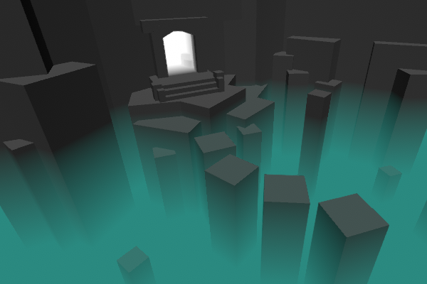
Intro This post includes two examples to produce fog shader effects. In both cases, the shader is applied to a flat plane or quad where the alpha of the surface is altered based on depth values to …
not a fan of just dragging stuff into the editor and getting the effect, I'd rather spend some time to learn the things that makes it tick
i could send you a sample project i made for a course at university, the effect the shield has on the pillar works identical
it's not urp though
but the logic behind the shader is the same
I think it's similar to the one Brackeys made ? https://www.youtube.com/watch?v=NiOGWZXBg4Y

Let's learn how to make an awesome force field with Unity Shader Graph!
● Check out Skillshare! http://skl.sh/brackeys15
● Support us on Patreon: https://www.patreon.com/brackeys
● Project Files: https://github.com/Brackeys/Force-Field
● Water Shader shown in intr...
Haven't really seen any of brackeys videos yet and don't have a lot of experience with shadegraph but from the thumbnail I'd say it's the same concept
exactly like that
I have some extra diagrams too that might help you
This is the code for that depth effect
@neon gull I'm slowly learning to "speak 3d space" .. I've mainly focused on 2d before and then I didn't really think much about near/far planes, clipping space etc 😄
So basically we sample the _CameraDepthTexture, and we take the red channel (.r) because as you saw depth was encoded in the red channel
I also divide by a distance property just so I can control the effect
I figured
near space = the nearest distance from the camera that objects will be rendered
far space = furthest distance from the camera that the object will be rendered
the cone that they form = frustum
I think 😄
and "clipping space" is vertex positions "as seen from the camera" i.e where the cameras view space has it's own coordinates that are different from world space
again.. I think 😉
ok so looking at the Screen Position.. I was skimming those docs before
Default
Returns Screen Position. This mode divides Screen Position by the clip space position W component.
Raw
Returns Screen Position. This mode does not divide Screen Position by the clip space position W component. This is useful for projection.
yes!
what is " clip space position W component"
again clipping space is "as seen from the cameras lense"
what's the W component ?
here is info about the W component
please be aware that this is from my personal notes, so grain of salt
but this is my understanding
so the w component is the depth, but relative to the camera
ok.. so x, y, z are simply the position relative to the camera lense.. W is sort of the difference (substract) betweeen the objects world space Z and the objects clip space Z ?
or.. hmm
yeah.. so W is in fact the distance between the worldspace Z of the camera and object ?
@devout quarry do you think that's an accurate description of W?
'w' is 'object depth'
So distance between camera and object yes
I'm no expert though so I hope other people read this but that's my understanding
But important to note that this is camera relative!
Important to consider that when working on effects or shaders that use it
Especially when your camera is very close to your objects
Because then, the distance between camera and object can change vastly based on camera orientation
If your camera is far away, this effect is less strong
Yeah but it can't just be the distance from the camera to the object thought? Wouldn't that be Z ?
hmm no if it was Z then would assume my camera was placed dead infront of the Z axis.. whihc it might not
Hmm no
Because camera near plane
Is not same as camera position
And clip space depth is relative to near plane
ah so z,y,z is relative to the nearspace and w is the distance from the actual camera itself
w = z + near plane ?
I think so yeah , that would make sense to me
Clip space is between near and far plane so definitely relative to those planes
But also I do think the orientation of the vector is different
Because w component right
Is relative to camera
and distance W is measured from the actual "lens"
So you can imagine a vector from camera to objecy
And z component is vector between near plane and object
and W would be the magnitude of that vector
And those two vectors are not parallel if you know what I mean
Yeah so w is a line between camera and object
And z is line between near plane and object
But those two lines are only parallel when the object is at the center of the camera view
That's my understanding
yeah that'd make sense since they start from different locations
Yeah and also like
'w' is a distance between a point and a point right
So that's just by doing a straight line from point A to B
But 'z' is distance between point and plane
yeah the magnitude of the vector that is formed between those two points
And for that, you need to take a line that's orthogonal to that plane
That's definition of distance between point and plane
So the difference when using an orthographic camera is that depth is normalized
Yeah I found his blog yesterday and been skimming it 🙂
This link I mean
found the thread on the water shader on orthographic camera

I've never used the Orthographic projection, but depth effects work slightly differently. I was asked about it on the official Unity discord, and after some research got it working, so might as well share a small thread here too. 🙂 #unity3D #shaders https://t.co/ng67JlV...
Likes
334
Ah cool!
so with a perspective camera and Eye scene depth.. W is the actual distance in units
Meters yeah
while linear would normalize that between near and fare plane
But
There is a difference between scene depth and the w component of screen position
Scene depth will disregard transparent objects
yeah because they're not rendered to the CameraDepthTexture
since they're at a later stage of the render pipeline.. only opaque objects are added to the depth texture ?
Scene depth is linear or non-linear depending on the mode you use, and distance is between 0 and 1 or in world units, relative to camera
Yeah that's the deal with 'forward' rendering I think
Opaques first
Then transparents
And so depth texture is generated inbetween
You can see this in frame debugger!
Scene depth is linear or non-linear depending on the mode you use, and distance is between 0 and 1 or in world units, relative to camera
I think it's more like
linear = 0 to 1 starting at the near plane and ending at the fare plane
eye = world units starting from the camera
as per your image https://media.discordapp.net/attachments/497874081329184799/671439990911139856/unknown.png

Yeah
and raw is .. umm.. 0 to 1 starting at the camera (and not the near plane) ?
I'm not too sure about that
or it's simply the alpha of depth texture
I think so!
It's the value of the depth texture yes
But so it's 0 at near plane I think
I really appreciate that you guys let me bounce my vague understandings of these things to help me solidify them 😄
It's 0 to 1 at the near/far planes, but isn't linear like Linear01 depth
e.g. A value of 0.5, won't be half-way between the near/far plane
oh looks it's @regal stag himself! 😄 Love your blog.. lots of goodies for a shader n00b like myself
Cyan if you see a mistake in my screenshots, let me know
Thanks 🙂
But afaik they are correct
@regal stag so how is 0.5 "determined" in a raw sample ?

NVIDIA Developer
Depth precision is a pain in the ass that every graphics programmer has to struggle with sooner or later.
This explains it
Yeah, so if you sampled the texture and got a value of 0.5 back
Depth precision is a pain in the ass that every graphics programmer has to struggle with sooner or later.
Glad it's just not me 🤣
I still don't know if my understandings are fully correct tbh
Lol fair
I've never had any formal education on this so never 100% sure
Only know things from personal research online
Same, self-taught
trying to wrap my head around where, in depth, 0.5 could be in a raw reading if it's not guaranteed to be in the mid-point between the near/far planes 😄
.w is the perspective divide. And it's going to be different for ortho, because ortho's perceptive is different. That's how I think of it. :2c:
Yeah, in ortho the w component should be 1?
Think so
because in ortho everything is the same distance from the camera?
Yeah

Computer Graphics Stack Exchange
Background:
I found that it is very easy to use a linear depth buffer, using only a slight modification to the canonical vertex transformation. The simplest method is found at the bottom of https:/...
more great reading material! Lucky I have 64gb ram with all the browser tabs I have as a backlog of things to read 😄
All this stuff is really interesting
@regal stag so wait.. it's for "Screen Positions" that W is always 1 for ortho, but "Scene Depth" still has a value right ?
Correct
I seldom have to worry about it, since it's usually done in hardware anyway. By the time it gets to the frag() function, it's been done.
The hardware needs to know so it can do early-z tests.
And it starts as a 1 in the vert (at least for normal 3d perspective) if you're generating your own clip-space in the vert.
Z is still there in clip space, and gets divided, yeah.
The Scene Depth node in ortho mode should be set to Raw though, as it already is linear
Yes
I'm looking at this from your tweets
Is Position (space = view) the same as Screen Position (but with a twist or you'd used the latter 😉 )
@regal stag ☝️

Stack Overflow
I was studying the rendering pipeline and when I got to the clipping stage it was explained that from the view (eye or camera) space we have to pass to the clip space, also called normalized device...
Trying to understand why you are using Position (with Space = View) and not Screen Position (i.e as seen from the camera)
I get that this part is simply to get the depth in the correct Z orientation
and for testing purpose (on a single platform) all that can be replaced (right?) with just Scene Depth (Raw) node
@meager pelican does that last post explain "Space = View" in the Position node in Cyans sample?
and.. no u still need to Lerp between the planes
as a way to convert it to units
Yeah it should help explain it, at least a little. The Screen Position is the normalised device coordinates, so it's different from eye/view space
my head is exploding 🤯 lots to wrap your head around when learning it from the start 😄
think I need to read this https://learnopengl.com/Getting-started/Coordinate-Systems
Learn OpenGL . com provides good and clear modern 3.3+ OpenGL tutorials with clear examples. A great resource to learn modern OpenGL aimed at beginners.
Ah yeah, that article is fairly good for explaining the different coordinate spaces
umm so View space is sort of a "raw" view from the cameras point of view .. the space ranges from -1 to 1 ? then when we move into clip space, we're in the space that's created when the View space is "clipped" by the area defined between the near and far planes? and those coords range from 0 to 1 ?
The view space is like world space but relative from the camera. I think.
since world space is the step before view
NDC/View/Clip/Screen spaces. Giving CG people headaches since conception, along with quaternions.
Note that OpenGL and DirectX have some differences.
Haha
World space = position in the entire world
View space = position relative to what I can see "from my eyes/camera"
Clip space = position relative to what I can see from my eye/camera while viewing it through a frustum
?
@meager pelican let's not go there 😉 currently my 3d world is all normalized to unity on windows with an nvidia card 😉
is that a fair approximation of the different spaces?
Uh, I think so
And what ranges are they operating in?
World space = positive/negative infinity
View space = positive/negtive range depends on the cameras fov?
Clip space = ?
The view space doesn't really have limits, it's just a rotated/offset version of the world in a way.
I think the clip space is the one which beyond -1 to 1 is clipped away.
at least for OpenGL
right so it's basically the same space, just as seen from the camera where the camera is the new 0,0,0 ?
Well, clip space is about "what's in the frustum". It ranges from -1 -> 1.0 with 0,0 being in the center. Z is depth of some sort.
So anything outside of -1, 1 ranges are "clipped" as part of the rasterization process. Now dealing with Z and W gets complicated, and that's where you have to dig into the links and see the differences. And also ortho = messes with my head. NDC and Clip aren't exactly the same thing (again, see link)
@wicked estuary Yeah
guys, you're literally saving me days here ❤️
The transformations between spaces is done by the difference matrices.
Object to World uses the "model" matrix.
World to View uses the "view" matrix.
View to Clip uses the "projection" matrix.
Clip to normalised device coordinates (aka Screen Position), divides Clip by Clip.w ("perspective divide")
The main thing that I remember is that the vertex shader outputs clip space stuff. The hardware knows how to do the perspective divide to get to the frag shader, and you have to set W properly in vert().
So after all that ^^^ matrix math, vert outputs clip-space.
I think.
Yeah, a vertex shader should convert from model to clip space and output the clip space position. It then does the perspective divide between that and the fragment shader.
Clip to normalised device coordinates (aka Screen Position), divides Clip by Clip.w ("perspective divide")
But only when using Screen Position with Default, with Raw you're still staying in Clip Space since it doesn't divide by W ?
Correct (at least that's my understanding of the Screen Position node)
So as a silly example.. I can create a simple shader that lerps between two colors based on the screen position (raw) X position .. so when the object is far left of the cameras view it would be Color 1 and on the far right it would be Color 2.. in the middle it would be an equal blend ?
Which is why the ztest thing in hardware is so cool.
If you get what it is doing, you realize that the frag() shader isn't even called for frags that fail the z-test (this is what I mentioned earlier for "early z testing")
I'd do it in vert() on the clip-space position, with a formula, and let the interpolators mess with the color value, rather than worry about the x pos in the frag/screen-space.
But sure. You can view many values "in color"...common debugging technique, you just remap them somehow to colors.
@meager pelican I'm not quite at the HLSL level yet so my brain isn't thinking in terms of vert() or frag() just yet 😄
that shader kinda helps to illustrate clip space quite well when u move it around in world space
I noticed that if I dragged my plane along the Z axis, the color changed
but then I realized that's because that translates to a change in X in clip space
hmm I just noticed that that shader only works with an orthographic camera
if I change it to perspective then it turns red
well sort of.. it fades if I drag it to the edge
ohh.. the type of Screen Space matters here.. changing it to Default makes it work in perspective
so this has something to do with that perspective divide thing
Yeah, well for orthographic, the Raw w component is 1, the perspective divide won't do anything in that case.
so is the perspective divide something like "flattening" our the positions in relations to the distance from the camera
sort of translating them to a single plane ?
if that makes any sense.. I don't even know anywhere 😂
It basically pulls positions towards the screen center, it's what handles the actual perspective projection
But yeah, objects at a further distance have a higher w value, so get pulled in more
so an X position close to the camera is the same as an X position far away from the camera.. i.e their clip space X are independent of perspective of which they're viewed
horrible way of explaining it, I know 😉
it takes the perspective out of the equation so to speak ?
Ok here goes.. both quads are placed on the same world space X but due to the perspective they are at different clip space X coords.. by dividing with W that difference is eliminated, giving them the same clip space X ?
@regal stag did I get that right? 😄
I'll be honest I'm getting a little confused at this point
😆 sorry 😉
Haha it's okay, it's not you. Trying to understand all these coordinate spaces can just be somewhat confusing in general.
but yeah I think that make sense.. they are rendering using the same color at those positions and they would only do that if they were returning the same screen positions
since the colors are lerped based on X screen cord
and we can clearly see that they're at different RAW X clip space coords
so I think that's fair enough approximation of what it means to divide by W in clip space
hopefully one I can live with until a tiny detail completely messes things up when I try and do something and will have to get an 100% accurate understanding 😉
@regal stag I'll re-read your fog shader breakdown tomorrow morning to see if my new insight into spaces increases my understanding of the techniques used 😄
If I have 4 vector1 properties
is it better, performance-wise, to put them into 1 vector4 and then access the properties using xyzw?
And if this is the case, at what point does it reduce performance? Because I could start putting properties into matrices?
And one other question
This is what I get with this graph
So using the vertex colors as color
but when I take split the vertex colors vector4 and use the R channel as color
I just get a white plane
instead of what I expected (black plane with white where I painted the red vertex color)
If the other vertices on the plane have a white vertex colour, that is going to include a R component of 1 as well as the red area itself.
You would have to set all the other vertex colours to black if that's what the output you expect is
I think the default tends to be white yeah. I guess it might depend on what modelling software the model is made in. I know blender at least defaults to white.
Okay thank you
Kind of annoying though, if I want to use a channel as a mask, I can't just start painting right away because every vertex already contains that color?
I need to 'clear' the paint first
@devout quarry Depends, on if they're uniform, or if they get passed vert->frag or what. One (a bit older) video from a GPU maker I saw said in essence "try to limit your interpolation to 4 float4's max for performance". You'll see the Unity shader code often "packs" things into float4's too for the "v2f" stuff.
And matricies and other data are often passed as constant buffers for the frame, or uniforms on the shader, or whatnot.
Memory access and alignment is often best by forming sizes (say of structuredBuffer data) of sizeof(float4) as I guess memory is most efficiently accessed that way, or in multiples that amount to that.
is it better, performance-wise, to put them into 1 vector4 and then access the properties using xyzw?
And if this is the case, at what point does it reduce performance? Because I could start putting properties into matrices?```Oh, and if you can do one operation on them (say adding 1 to all of them) then by all means VECTORIZE them. Vector ops usually happen in one institution. SIMD type of thinking.
Ah interesting stuff
So like for a wave
I should put the characteristics in a vector4 all together
let's say (speed, wavelength, amplitude, steepness) or something like that
A lot of this stuff is hardware and engine dependent.
Unity makes "blocks" of data to pass up to the GPU when needed for many things. Hence the term Material Property BLOCK for example when dealing with instancing.
For a vector4 vs 4 floats...I'd assume one call to SetVector is faster than four calls to SetFloat. Just less function call overhead. But who cares unless you're doing 1000's of them?
For uniforms, IDK.
The engine guys would have to pipe in for more details, and/or to correct me. Maybe others know more.
The thing is that shaders are limited by "vector register pressure" too. So there might be a point of diminishing returns, and in fact it may all vary depending on the compiler and the optimizations that it does. I just know some "general rules" and I let the engine do its thing.
Hi. i've been using shadergraph mostly writing HLSL into custom function nodes as a sort of visual shader prototyping environment which i find very a powerful tool, however ideally i would really like to render the results of the shader graph directly into a Texture2D or Texture3D, to have multiple buffers and feedback, etc. which as I understand would require a new Shader Graph type. I'm using HDRP but i've heard the URP may have some functionality related to this? or is anyone aware of a RenderTexture ShaderGraph already being on Unity's roadmap?
you can also see my recent messages in #✨┃vfx-and-particles for a use case and some backstory but it's not purely related to that use case, this is something i've been meaning to dive into ever since shader graph was announced as a viable workflow (though it's currently not very as its not shader graph's most essential use case, i.e. defining surfaces / materials similar to a digital content creation suite.)
though I am hopeful for conveying the importance and usefulness of this feature. Take this as step further into the concept of a compute shader graph which would be amazingly powerful and educational for many as well.
@fossil cedar https://docs.unity3d.com/Manual/class-CustomRenderTexture.html should still work but not with HDRP shaders
but like, should be able to author CRT compatible shaders and use the generated CRT on HDRP shaders / shader graphs still
Amplify Shader Editor also has node graph support for CRT's I think, but it's 3rd party solution
some LWRP SG's also worked on that CRT but I never had success with HDRP ones
(and once you compile generic PBR Graph on HDRP, it stopped working on CRT when I tested it)
it's probably not a big difference and I never really investigated what breaks it on HDRP shaders but point is, you can still author things for it manually

GitHub
Vehicle snow tracks shader graph test using unity "custom render texture", unable to get Graphics.Blit to work for a render texture/ - tim-neville/Snow-Tracks-ShaderGraph-Unity-2019.1
that uses LWRP unlit SG to feed CRT
i found that repo also, but haven't cloned it yet
thats the LWRP / URP wacky workaround i heard about.. you install URP, create the shader graph asset, then uninstall URP and install HDRP lol
well, that's probably my comment on that thread
basically it breaks the moment you compile the shader without LWRP/URP installed
if you have both LWRP/URP and HDRP installed at the same time, I managed to make it work
aha, that's hacky but makes sense
there's basically something missing form HDRP unlit shader, so if it generates it for LWRP/URP, it's still comptible with CRT
I haven't checked what it needs, like, if it would be possible to fix with simple change on the generated HDRP shader
and if it would be something Unity woud be willing to include on stock HDRP
because it sure would be handy to have
right, exactly i think we can get it on the roadmap / backlog at least if it isn't already
do note that I haven't checked how this works on recent Unity and HDRP versions
you could yes
" works under URP but not HDRP, reproducible" 🤠
just make sure you have a repro that's super easy to replicate
if you attach simple repro project, your chances on getting anyone to figure this out get way better odds
yeah good point
I'd assume otherwise it'll just end up on the backlog
also should make sure it really breaks on most recent HDRP as well
hmmm, wonder if I still have my HDRP port for that project somewhere
could test it easily I suppose if it's still there
found it, altho I dunno if this had everything upgraded to HDRP yet
this was for 2019.1 / HDRP 5.16
but I'll just upgrade it to 7.1.8
i also found LG electronics actually forked HDRP 5.1 and made their own custom render texture shader graph
i got it to compile in HDRP 7.1 but i gave up trying to get the shaders its codegen spits out to compile lol
I mean if it's not a big change in the stock shaders, it's not really that difficult to mod either
main issue with these is that you can't just extend HDRP to use new shader template like you can with ASE
because LG's approach was either a bit hacky or it didn't uses some code gen util libraries that unity refactored a bunch of shader graph code into
so you gotta modify the whole HDRP which is then pain to maintain
but the code is on github and can be used as an example case to Unity
i'll link u soon on my phone rn
tbh, I have a feeling that CRT shouldn't even work with LWRP/URP unlit, but it just does 😄
if you look at the CRT docs, you should use shader specifically meant for it
* #include “UnityCustomRenderTexture.cginc”

    Use the provided Vertex Shader InitCustomRenderTextureVertexShader

    Use the provided input structure v2f_init_customrendertexture for the pixel shader
docs have been wrong in past tho
right and that was written before SRP was really officia i think? but cant have been that long anyway i think Custom RTs were released in 2017 but for built in / legacy pipeline
if I remember right, you can't just go including that cginc on HDRP shader either
legacy shaders includes usually break in all directions with HDRP shaders
I don't think SRP shaders have ever meant to support CRTs
right though i could try in a custom function node, they support includes.. but maybe only applies to the scope of those custom functions
you can still technically run the old shaderlab shaders for CRTs even on HDRP
it's just, would be nice to be able to author the shaders in SG
right yeah that's the idea, since its so useful
and i have no problem with doing it all in code but i interface with many artists and it's very powerful to make abstracted tools for them and myself to approach design iteratively.
the domain specificity of shader graph and visual effect graph is powerful as well for those domains but it's also significantly limiting versus a general purpose node graph paradigm
still seems to be no-go with unlit graph and HDRP 7.1.8
@fervent tinsel btw here's that LG repo with the fork of HDRP 5.1 and the custom RT shadergraph type https://github.com/lgsvl/simulator/tree/master/Packages/com.unity.render-pipelines.high-definition/Editor/CustomRenderTextureShaderGraph

I'll try hacking that URP to compile the shader
thanks
how did you find that? 😄
i have a hacked up version i grafted some of HDRP 7.1 into and the graph UI works but the shaders it generates don't compile and realised we'd be better off forking HDRP 7.1 from scratch to add new shader graph types
yeah though it also has a bunch of codegen they seemed to have moved to a reusable library with some pretty funny abstractions lol a template factory if you will
it makes sense though, building powerful directed node graphs tend to go this way
I really wish they would let you just do this on actual project, instead of having to modify the HDRP
yeah, they are adding more and more injection points for HDRP so i see that as a possibility
there's really no custom SG work done afaik
like you can do custom passes and pp passes
but only thing I know is that they are working on custom pass graph
right though whatever refactor happened under the hood should make it better than when LG did it in 5.1
you can use SG's to some extent already with current HDRP's custom passes
the templates have significant fat trimmed but even the unlit sg template is still massive to account for so many shader variants
I could look into porting this into HDRP master at some point as I'd really love to have this.. it's just I don't look into maintaining this so it's bit too early to do it now 😄
yeah i wanna see what unity devs will say first
yeah, it's kinda bummer we don't have any really working feedback solution for requests like this
if they are planning to release this in 2020.1 or 2 anyway then why waste our time
yeah those are the magic words though
reproducible, regression, there's gotta be one more...
really useful? lol
currently trying to get URP compile that unlit graph on that project now
it still kept putting on HDRP despite I was running on URP asset
just wiped library to enforce it 😄
still hdrp shaders...
I wonder if this is somehow enforced at asset level now
in the older SRPs SG's, you could even swap the SG master nodes from the graph
I don't think that's possible anymore
btw, I'm trying to interpret that LG repos license
it sounds like they claim all rights for their modifications
I dunno if SRP's license even allows them to do that
yeah, fortunately it's garbage code already
but is still useful as a reference/ proof of concept
I dunno, only thing worth anything there is the template
technically one could mod URP template too, as it's supposed to work
right it's more like, ok Unity obviously an important company like LG wanted this so much they had some engineer waste their time forking HDRP to do it
so can you pretty please put it on the roadmap for 2020? 
people have requested tessellation graph and terrain graph for years already
and those are obviously way higher prio things
but obviously still low prio things as we don't have them 😄
aha but this is a very active time of development and like you said technically a regression
technically it also still works with the manually authored shaders 😄
you have your 7.1 port public btw? or just locally done it?
which are barely supported in HDRP, shader graph is the #1 way they want shaders to be written in HDRP
I'm mainly interested which all files you need for SG side of things to put a new graph type nowdays
and this is a pretty easy use case to understand
@fervent tinsel its garbage i hacked together quick and idk if i'm allowed to make it public anyway. but message me if you want to chat about those details specifically
I'll look around first
So I am using this to change my Shader Graph material property.
materialBlock = new MaterialPropertyBlock();
materialBlock.SetFloat("_CoverVariation", Random.Range(0, variationDepth));
meshRenderer.SetPropertyBlock(materialBlock);
Its a simple float variation
But I get this in the frame debugger.
Non-instanced properties set for instanced shader
It says it cannot be batched because of this
Am I using material property block wrong? Why can't it be batched?
I thought anything except for Textures can be changed safely with material property block for it to be batched?
shader graph properties are not currently compatible with material property block
is there a way to share a shader graph node value (e.g. a gradient noise node) with a script in realtime
cause I need to get the Gradient noise as a texture for my script
or at least, is it possible in regular shader code?
@fossil cedar I did get that thing ported to latest github HDRP/staging (using it from 2020.1)
and it does work
just redid the graph using clean CRT graph and hooked it into CRT on that snow track demo project
there's probably still tons of things done wrong but at least it works
@distant pawn reading values from the GPU (shader / HLSL) to the CPU (C#) can be tricky and has caveats, but not impossible. you typically want to keep things a one way street.. CPU -> GPU -> Display. But there are plenty of use cases for doing otherwise, like general purpose GPU compute with compute shaders, etc. Yes, It's possible and better at the moment to do this sort of thing with "regular" written shaders at the moment if needed. Or if you can get around it and just use some noise functions for C# that would be better assuming you don't need massive parallel processing
@fervent tinsel you mean you the URP trick with the Unlit ShaderGraph? or you implemented a Custom RenderTexture ShaderGraph ?
@fossil cedar would there be any documentation on it?
I ported the CRT Graph
I think subgraph support is still partially broken
because once I moved something from main graph to subgraph, this thing completely broke 😄
it does seem to work with one main graph still
okay well like i said i had trouble with it as well but at least you got some shader to compile at all from it
yeah, I swapped to new shader includes
plus had to update ton on the cs files
but there's obviously still some things wrong on the subshader part 😄
I'll see if I can redo this from scratch at some point
now at least I have some idea how this is setup
@fervent tinsel yeah I think I was close i was just trying to get the surface description struct and the includes sorted out in the generated shader and was like enough for tonight after pouring through so many thousands of lines of C#. Thanks for looking into it anyway, I'm glad it piqued someone's interest.
@distant pawn Here's a pure C# / CPU method to generate values from a perlin noise gradient. I'd scroll down and use the one dimensional version if you just need one value or a few: https://docs.unity3d.com/ScriptReference/Mathf.PerlinNoise.html
Or if you really need to read back to the CPU with C# from a Texture2D on the GPU, (presumably a render texture with the result of some shader,) you might use this or one of the methods mentioned in this doc:
https://docs.unity3d.com/ScriptReference/Texture2D.GetPixel.html
the main issue when dealing with stuff like this is that you end up going to the undocumented part of the SRP and there's a lot of things to figure out if you really want it work perfect
I wish we engine users would get at least some google docs etc design docs for these systems, or some notes
but the current stance seems to be that only public API needs documenting for end users
I assumed Unity has plans for that but they are waiting for development to slow down enough they they don't have to rewrite the docs every month
2020 seems like a good year for it though
I'd expect at most some technical talk about specific systems, like we've seen so far
they must have some internal docs though like you are saying, something rough in a shared internal document
they have plenty of those as they are often linked on SRP PR's
it's just they are not public for all
oh yeaaah i do remember coming across those private doc links on github before
also lol @ that LG 3rd party license file. They got GPL licensed stuff there... which is direct conflict of most other licenses they have there
it is a bit ironic that those docs are private, while there has been this whole initiative to share source of all the new packages, and SRP... those docs are relatively useless on their own, yet they would probably add a significant amount of value to the code
to be fair, there would only be limited amount of users who'd actually want to modify the stock SRPs
and I can imagine studios that do mod them have paid support from Unity so they get access to the info they need directly
yeah, most probably have an engagement with Unity already
and yeah i mean honestly who knows if LG even wrote that Custom RT shadergraph code, they maybe lifted it from somewhere else or it's something they paid a Unity dev to throw together custom one day for all we know
as for the CRT thing, I can DM you my current changes (if you want them that is), I dunno when I'll have time to properly do this
I'm fairly certain those fall under that Unity companion license anyway
the reason I even looked at this is because I do need this for my main project eventually, it's just been on my backlog for ages with low priority
I was actually going to go with ASE route but having SG support would be nicer
hey there I'm trying to use the Fog node in shadergraph but with a unlit master node. While the unlit master is active density always returns 0. If i set a PBR master to be active then the density returns correct values. Anyway to get it working with a unlit master node ?
Need really quick advice for Shader Graph
If Im using a mask to change normals
What node should I put into the rest to get the original normals for the rest of the mesh
SO what should go into A in the LERP
do you mean the mesh normals or a normal map ?
Mesh Normals, but I think I already got it, the 'Normal From Height'node seems to do the trick
for mesh normals you should use the normal vector node no?
@regal stag @meager pelican the coin dropped on why things are divided by W. Make objects further away, from the camera, to be pushed towards the center hence creating the perspective
so anyone have any ideas on my Fog node problem
Does having separated nodes from anything else affect performance in the shader graph?
Like having a noise node but it's not attached to anything
@kind helm I highly doubt it, but you can always check in the generated shader code.
@kind helm as far as I know and by looking at the generated code if the node does not lead to the active master node it does not affect performance. Not sure if gets generated into the code, it used to.
Okay thanks!
can someone give me an advice on how to generate tileable procedural texture using RT or CRT?
@distant pawn <sharing data> I already answered that for you. And some of @fossil cedar 's post just said the same thing. Drive it with known values from C# and use your own funcitons. You can't expect SG's functions to be the exact same math functions as in C#'s "gradient" and "noise" functions.
YOU supply the functions and data. Then YOU will get the same outputs for the same inputs. You have to have an authoritative source of data.
What part didn't/don't you understand on this? Confused here.
You're not going to get SG's library to guarantee that it produces the same results as C#'s library for all noise functions. PASS THE DATA from one or the other (C#->SG is easiest).
Or write your own math-based funcitons on both sides, and hope the floating point math is so standardized that it "works out" (doubt it).
In real-time or in an editor?
both
Oy.
In an editor, you can "chop" up any texture, and reorient the pieces to get a tileable texture. The way that is done, is to cut it down the middle horizontally and vertically, and swap corners, and fixed up the new-middle. I suppose you could project points mathematically to do that too. But "fixing up the middle" might be tough.
That works because what was the center becomes the outsides...so they "tile" seamlessly. But the new-middle gets messed up.
Basically, it's a symmetry problem, so if you could mathematically make it generate things symmetrically in the quad-divisions of the texture, it will tile. You can probably find some algorithms if your google fu is strong. But I can't help further, maybe someone else has a ref.
Hello, under LWRP there is an unlit shader. It does not have an option to rotate the sprite. Does anyone know how to do it?
the sprite? do u mean the texture?
so the texture
I'd like to be able to rotate it. So I went ahead to make a shader graph
do u need to color it as well, or just take a texture and rotate it?
Which is done under Create > Shader > Unlit Graph
But this is how it looks like. I don't know why it's empty. Shouldn't it default to have the options like in the LWRP Unlit?
I'd like to have the same surface inputs as in LWRP Unlit but with the extra rotate ability
ok
so in shader graph u have the "blackboard" .. u can open it in the top-right corner of the shader graph window if u dont have it opened
anything in your blackboard can be exposed as a property
that's what it looks like empty
Ok
say I have this simple shader
notice that I have a Texture 2D asset in there
but it's an inline property now
if I right click on that and choose Convert To Property then it will be moved to my blackboard
Let me try it
u can give it a name there and make sure that the Exposed property is checked
save your graph and it should now be available on your shader in the unity editor
What is the difference between Sample Texture 2D Lod vs non Lod?
sorry I was meant to use the non-LOD in my sample
LOD is "Level of Detail"
u know how u can adjust the level of details in games depending on your graphics cards power etc
control how much detail is displayed etc

A Unity Scriptable Render Pipeline tutorial about supporting crossfading LOD groups and shader variant stripping.
now sure why your master looks different, maybe different URP versions? I'm pretty new to all of this myself 😄
there u can see the rotation in effect
I added a rotation property that you can control
the rotation property is simply a Vector1 which u can think of as a float
Bookmarked the link. Gonna read it before bedtime
Hmm... I guess that's the reason but nevermind that
Hang on still working on the graph
@meager pelican in view space, where is (0,0,0) located? Right at the cameras position? Or is the X & Y at level with the camera and Z=0 is actually where the near plane is ?
@regal stag oh guess I can ask you since you're here 😄
Those LODs are more for object/mesh levels of detail. The LOD in sample textures is more to do with choose mipmap levels, where you can choose the mipmap level, while in the normal Sample Texture 2D node it handles mipmaps for you. (Smaller blurred versions of the image, less detail at a distance).
did u change that on your master node?
This is with the default unlit
normal texture work fine too but not transparent one
might need a lit texture to set the alpha though
If you want to replicate that, the master node needs to be set to Transparent in shadergraph, otherwise alpha won't be taken into account (unless you use alphacutout/clipthreshold that is).
It has transparent
oh u need to hook up the alpha edge as well
drag the A from the Sample Texture to the Alpha on yoru master
ITS WORKING!!
that's with a transparent texture that's been rotated
Sorry I was happy lol
Cool!
@regal stag in view space, where is (0,0,0) located? Right at the cameras position? Or is the X & Y at level with the camera and Z=0 is actually where the near plane is ?
Let me try out tiling and colour myself and get back to you
tip: color = take sample texture output and multiply with a color
tiling is straight forward
@tall chasm let me know if u get stuck. I added color and tiling to my version
@wicked estuary I assume it's at the cameras position. I think the near/far planes are probably included in the projection matrix conversion to clip space, as then it clips outside the viewing frustum based on the near/far.
yeah that makes sense.. anything between the camera and the near plane, after converting to view space, will be clipped
so if (0,0,0) is as the base of the camera, there's a dead zone between the camera and near plane
Thanks, will brew some extra strong coffee and get reading 😉
But yeah, any objects between the camera and near plane won't be rendered. That happens in clip space though, not view
yeah
The inspector views Vector2/Vector3 properties as Vector4's, you can ignore the other components
Or if you want, you can combine your two Vector2 tiling and offset into a single Vector4, with the XY components as Tiling and ZW components as Offset. (Then in shadergraph you'd need to Split the Vector4 and put the correct components into Vector2 nodes though).
Awesome! But I dont understand why vector 2 property is showing "Z" and "W"
@regal stag Ahh ok I understand now!
@regal stag @wicked estuary Thanks a lot for the help!
It's because there isn't a "Vector2" property in shaders, it's just a "Vector" which has 4 components. In shadergraph we get versions of these, but Vector2/Vector3/Vector4 will all be considered "Vector" properties. The "Vector1" is different though and is converted to a Float property.
@regal stag Ok that makes sense
@tall chasm happy to be able to pass on my limited shader graph knowledge to a fellow learner 😄
I really appreciate it man 🙂
making a tower defence game?
can't tell, from that perspective, if it's a turret or a tank
@wicked estuary haha kinda. More on survival tho. Building turrets is one of the thing in game
@lone stream Interestingly, there's this that just came out:
https://docs.unity3d.com/Packages/com.unity.shadergraph@7.1/manual/ShaderGraph-Samples.html
So certain patterns have that inherent symmetry.
ooh i should check that out
@wicked estuary I think z=0 in clip space is the near-plane. Screen Space is 2D with a depth buffer. But for View space....that's "just" camera relative space, and I think Cyan is correct. IDK for sure, since I seldom deal with it directly, but putting z=0 in view space might clip it because it's too close to the camera and the near-plane is further out.
Because in view space the camera is at 0,0,0
👍
Hi. Tessellation in Shader Graph: will this be a thing (any time soon) ?
ok. thx 🙂
Yeah big pain in the ass that they havent done this yet :/
Also today I found out that you cannot use a texture to mask anything that goes into position
However, this was on 2019.2.15 so it might have been fixed by now
I ended up doing it via vertex painting
Do you mean sampling textures for Vertex Position?
No
It was a test in class, we had a model, and had to do different effects on different parts of it
Hq trivia
So I made masks for each on the sections in Substance Painter, black and white masks
when I plugged the mask into T of a Lerp node, it could no longer be plugged into the Position
But when I used a vertex color channel as a mask in T of the Lerp node, it did work
Yeah but, were you using Sample Texture 2D?
Because only the Sample Texture 2D LOD version can be used in the vertex stage of the shader
Yes I was using that! I noticed when I pulled out of the Lerp and tried to make a texture node, only the LOD was an option!
So why is that?
because of mip mapping
in hlsl the standard sample function has a dynamic mip level but the vertex shader requires static values of the mip level, which the sampleLOD function lets you declare once
Cool, my teacher didnt notice that issue, so I'll teach him something next time I see him
So if I had used the LOD Sample Texture, it would've worked fine?
yep, that can feed into the vertex slots with no issue
Awesome, thanks!
it does also point this out on the documentation pages for those nodes
i know the discoverability of docs isn't great at the moment, but it is there 😅
Oh the documentation of Unity is pretty good, better than Unreal
It just didnt even occur to us to look at the documentation of the Sample Texture Node. We thought it was just a strange limitation.
The documentation is often a little too confusing for me though, since it is written very technically. Since I dont know the backend of shaders that well, it can be difficult to decipher.
luckily shader graph is just a visual abstraction layer of HLSL, which is pretty extensively documented and discussed
if you have any issues with the shader itself you can google "hlsl + [issue query]" and usually get the shader-level explanation
It'll be difficult to read, but I suppose I'll learn more from it. I'll give it a try next time.
Programming really isnt my forte
and shader programming is on another level of complexity than "normal" programming 😄
@mortal sage you know the workarounds tho?
altho how usable they are depend on your application
you still can feed stock HDRP tessellation shader data through render textures which you can modify runtime
we just had lengthy disccusion last night about getting CRTs working on HDRP
(custom render textures)
@fervent tinsel maybe something possible there not sure how convoluted that would be in regards to tessellation shaders and what performance drawbacks there might be... @mortal sage currently i'd just skip shadergraph if you need tessellation.
Interesting thing is Mesh Shaders were just announced to be added to DirectX to replace the decade old Tessellation and Geometry shaders so it would make more sense for Unity to add Shader graph support for that at this point
you'd need DX12 for the mesh shaders tho, right?
it's quite niche audience then
I guess that really boils down if both upcoming consoles support that
in SG, what is the difference between the normal and the vertex normal slot?
vertex x slots happen in the vert() function of the shader, the other slots happen in the frag() function of the shader
Hello guys, tiling doesn't work with transparent sprites?
@fervent tinsel @fossil cedar Thank you I'll have a look into these things. This is for a quite complex custom terrain shader done in shadergraph, I am trying to figure out what would be the best way to add displacement. Maybe parallax occlusion mapping will fit better but it makes the graph much heavier
not sure if tessellation would be any cheaper
I also wonder what's the deal with the tessellation graph being issue as the change between HDRP Lit and HDRP Tessellation shaders is mainly just tessellation properties, two includes, few pragma changes in general + 2 extra pragmas per pass
it seems so simple so wonder why they don't do it