#archived-shaders
1 messages · Page 127 of 1
No i haven't...
Thanks you i will try it 🙂
I'm assuming that you are converting a project to use URP?
No i create URP project since beginning. But i have some problem that Shader graph doens't have option about stencil buffer. So i try to use shader file in urp.
Ronja's Shader Tutorials
Summary The depth buffer helps us compare depths of objects to ensure they occlude each other properly. But theres also a part of the stencil buffer ...
@strange onyx im familiar with the DICE/frostbite approach, id guess they simply multiply it by the number of slices, ex 0-1 texture * sliceCount and floor it
the values they choose for each slice ID would be some 0-255 value that comes from dividing 255 by the number of slices
(the values in the original texture channel that artists create)
The graph I shared should be accurate according to a DICE dev. The one thing I have affirmed for sure is the slice is essentially a texture form for index input in a texture array.
I also have working results from that very shader using ripped assets and textures.
The one thing I managed to screw up there was simply not swapping from gamma to linear lighting. It made the result slightly off.
I also managed to scale it incorrectly, but that's not completely relevant. the only thing I wasn't 100% certain on was combining the derived detail and base normals. There should be shadergraph nodes to do things cleaner now compared to when I attempted it back in early HDRP beta.
compare to this variant where I didn't have it implemented. You will immediately see how much smoother the armor looks, because there was no details applied.https://twitter.com/N00b_B1scu1t/status/1097920395964006406
That said, this still looks much better after a bake than before one. I have been using shadowmask, so kinda curious how enlighten will change the outcome.
This was a partial bake, and I didn't like the outcome. Gotta figure out how slice maps/tiling normal maps work.

@uncut karma thanks, that's much easier way
hey all! is it possible to use _CameraDepthTexture without realtime shadows?
or maybe a better way to ask this: I know the depth texture is rendered during the shadow pass, but is there a way to render it on its own without all the overhead from the other shadow stuff?
@dusk ravine Yes, by setting this property on your camera to DepthTextureMode.Depth
https://docs.unity3d.com/ScriptReference/DepthTextureMode.html

Can only be change from script
Does someone have a good eye asset/prefab/shader for HDRP ?
Look like HDRP is out for a year and there is still no content around
the RP stuff was kinda just dumped out there.
I want to "extend" the default terrain shader with a grayscale calculation and lerp (I need to transition only the terrain to grayscale) - what's the recommended way to extend a default shader? looking online, some places recommend #include (though I don't know the actual source path), some suggest UsePass, some recommend copying the shader source and adding a new block
include if you want to use a function from the file, usepass if you want to use the original pass and then a second pass of your own which is usually a waste of drawcalls, copy the source if you want to modify the existing code which gives you the most options
I want option 2 but don't want to waste calls, so maybe option 3?
I agree... That what I did with the standard shader so I could an an OPTION to cull backfaces or not. That said, it was actually kind of a pain to figure it out.
Then again, thats prolly also cuz I suck.
option 3 I would say is the best choice in most situations but it can also be a bit tricky if you don't understand the original
I've done that once before for the standard so I'm sure I can figure out here, but I'm still a shader noob so I'm just questioning everything
for now I don't want to do anything other than just take the result of the default shader and grayscale it
sweet that was easy. copied the shader source, modified the piece I needed, and it works
I'll likely revisit it later and do a better job once I know more about my needs. thanks!
We want a screenshot!
day 1 temp art but the terrain is a grassy texture and it comes through perfectly. I use a float to lerp between the actual coloring and the grayscale effect
Hello! I am not a great shader programmer, so I am using shader graph. I have a health bar that is entirely powered by a shader. I'd like to add vertical graduation lines for along my bar where the thickness of the lines are agnostic to the dimensions of the image.
Not at my computer, but I can share pictures shortly.
Trying to achieve this effect (ultimately including both the thick and thin lines). Using just UV tiling will compress the lines' thickness, which is what I want to avoid.
Anyone know a workaround for URP and pixelation when large tiling values are used?
Even with a ShaderGraph set to "float" it will use halfs internally for UVs and pixel the crap out of everything
"large" = 50 or so, pretty normal for a larger object I'd say
@gilded lichen Even with a ShaderGraph set to "float" it will use halfs internally for UVs and pixel the crap out of everything
You're kidding!
Just a thought, and I know better from you so no offense, but just on the off chance: did you check if it's a "point" filter mode on the texture or sampler?
I'm not kidding 😉
lol
(and no it's not point filtered)
(I'm currently hacking around the issue by copying the shader code and modifying all places where uv is defined as half, but that's, like, a really bad workaround)
I'd put in a bug report that it didn't honor the float setting.
Where could I get detail information about renderer features in asset renderer?
I have a question about using DrawMeshInstancedIndirect: is the per instance setup function defined with #pragma instancing_options procedural:setup called once per instance, or once per vertex?
The documentation says "At the beginning of the vertex Shader stage, Unity calls the function specified after the colon. [...] Unity also calls this function at the beginning of a fragment Shader if any of the fetched instance properties are included in the fragment Shader."
But I'm not sure how to interpret it.
The 2019.2 doco says:
At the beginning of the vertex Shader stage, Unity calls the function specified after the colon. To set up the instance data manually, add per-instance data to this function in the same way you would normally add per-instance data to a Shader. Unity also calls this function at the beginning of a fragment Shader if any of the fetched instance properties are included in the fragment Shader.
So per vertex???????? I get your confusion. They use per-stage terminology, but talk about it like they call it per vertex/fragment. You'd think it would be once per instance, to set up the instance-data.
EDIT: Bgolus does it again:
https://forum.unity.com/threads/gpu-instance-shader-question.536680/
Unity Forum
edit: SOLVED
I'm trying to use a function that runs only once on each instance using
#pragma instancing_options procedural:setup
int myInt...
That's exactly the information I was looking for (but not the answer I wanted ^^). Thanks!
oh.. NEVERMIND-- I''m just an idiot!
Hi guys does anyone know if something like this is possible in LWRP ? I've been trying many things with triplanar projections and all I get is shit

polycount
Thanks for the reply man!
this is a main issue in our game
thanks in advance!
Does anyone know if changing the renderQueue of the standard shader is supported?
I'm trying to change it on an instanced material at runtime and it doesn't seem to have an effect.
In case anyone has a better suggestion, the use case is that I have 4 player slots in a selection screen, where the selector objects are 3D objects in a perspective camera view. I want to sort their rendering times based on the slot of the players so they don't cut into eachother.
I can't use a custom shader since the selectors are using actual models and I want to be able to use the standard shader those.
Anyone knows how to convert any non-screen position into screen position in shader graph? (or the reverse is fine too)
(yes still looking for the answer after 2 months)
@cosmic prairie When you say any non-screen position, do you just mean world space positions?
So, you don't want the screen position of the object?
Just the screen position of any Vector parameter you give it?
wait nvm I figured it out FINALLY , so basically you need to split view position, divide itself by the z, multiply by projection transformation matrix, multiply by 0.5, add 0.5
thanks anyways lol 😄
I cant believe I was strugling with this for so long
finally I can reconstruct scene normal too not just screen position texture
for the fake lights and decals and stuff
in URP
Hello,
I am trying to activate the alpha cutoff on the TerrainLit shader, but after many attempts at modifying the shader code, I failed miserably... cos am a shader noob...
Does anyone know what I should do (if feasible) in order to activate the transparency/alpha cutoff on that specific shader (from the new terrain tool)?
(I have a texture with transparency (holes) on a Terrain Layer and I would like it to be taken into account)
afaik, gradients cannot be exposed in the inspector, which is why the expose option is greyed out in Shader Graph
I've been looking for info but it seems like there like 4 or 5 different ways of making custom nodes on shader graph
What's actually the best way?
Hey guys! I'm trying to do an object space shader for a Shuriken particle system. The issue I'm running into, is that the object space part of the shader is being ignored and instead is treated as a world space coordinate. Anyone has any hints about it?
My particle system is marked as local space simulation
Just a question about shader performance. What is more intensive?:
A: Models without textures and materials, all rendered with just shaders.
B: Models with textures and materials and just post processing
You see, i am creating a building system, which requires me to resize and reshape objects all the time, so just making them simple flat cubes is easier, as it does not stretch or mess with the looks of the objects. But ofc they cant just be grey blocks, so i thought maybe i could make the shader do all the work on those specific objects
That's waaaay too little information
I'm using this NdotL group of nodes
what I want however is to be able add an 'offset' to the main light's direction, so that the 'lit' side of my objects don't really match the actual direction of the main light
but just adding a vector3 offset to the main light isn't producing the expected results
okay nvm turns out it is working with some normalize nodes added
@oblique coral it's faster with textures than procedural shader texturing (mostly because GPU's are designed to be able to sample textures quickly I believe), especially if you would use Min() and Max() functions and if statements in your procedural shaders
thanks @cosmic prairie 🙂
@kind helm there's only one supported method of custom nodes in shader graphs, using the custom function node in the 19.x editor cycle to inject either strings or file includes to your graph. c:
@gilded lichen what platform? on PCs and Consoles, that half will become a float on your GPU anyways
half has only about 3 digits of precision after the decimal. So with a tiling of 50, and all the math (uv * tiling + offsets) and having a decent texture width/height, he's screwed. And he knows that's it because if he changes it to float manually, it works.
lol Prolly fine for low tiling #'s and reasonable sized textures.
And you probably can't see it on the desktop, of course, which as you say is going to use floats internally. So wait to see on platform-specific testing. Must totally suck.
Just had to throw that out there, to mouth off (and add support for his cause).
Hello,
I have a problem with mimicking a UPR/Unlit shader texture sampling in custom ShaderGraph shader. How can I make ShaderGraph generated shader handle mipmaps the same as Unlit shader? In the picture below you can see Unlit shader result on the left and my ShaderGraph shader on the right. As you can see on the right the texture is "cut off" above some ditance.
Where can I made a BRDF Shader in Shader graph
something like this
here is the texture
hey there! I have an issue with the flipbook node on shadergraph with HDRP, it looks like the animation comes back to a earlier frame each 0.5sec, and also it's kinda sliding, have you seen this before? Can't find a way to fix it...Looks like it's a precision issue with Time, maybe?
the graph, pretty basic stuff.
the texture is a 6 by 6 flipbook
I've heard somewhere that "Time" is not a precise value, but I didn't expect to be that bad
I tried to send instead a value for Tile directly by script, and while I don't have the slide issue, I still have the "rollback" issue:
@mental sentinel hmm maybe try creating a making a custom flipbook subgraph? or double check if the tiling is correct on the texture
I mean the order of the tiles
actually I've tried it on legacy with amplify and it worked well
looks like 4 by 4 works, but not 6 by 6? 😮
hmm does 8*8 work?
I'm trying to find flipbooks online that matches different values
okay
8 by 8 is fine...
damn
I will go with it I guess haha
thanks for the support
5 by 5 is broken as well.
I could turn my spritesheet into individual sprites and send the correct sprite trough script, but this is annoying.
for such a simple thing
I have a fairly complex hex-map mesh that I'm using for terrain. This mesh needs to change as the terrain erodes/deposits soil, during runtime. Rebuilding the meshes from scatch is slow, so I'm working on an update function, that will, hopefully, be faster. But before I get to deep into that, I'm also considering switching to a "skinned mesh" (which I've never used before) where the bones are the elevation for each hex. Would this be an appropriate use for a "skinned mesh", or would having such a large number of bones, render it inefficient?
oops .. meant to put this in general... pls IGNORE
@mental sentinel its probably 1x1 2x2 4x4 8x8 16x16 32x32 64x64 that work
ye, but it could probably work with other values if you make a custom node
but it's best to keep everything the power of 2 I think
I will try to copy what does Amplify Shader Editor do, because it's working with it, inside a sub graph. Thanks!
why does out of nowhere my scene turn white
hdrp is buggy
this is when i toggle the skybox off in the viewport wtf
the documentation everywhere is completely outdated
it's because the 19.3 is not released yet
lol
LTS will come when 2020.1 will be released
@cosmic prairie it worked!
So they're saying don't use HDRP until 2019 LTS unless you're ready to a lot of maintenance.
k
i dont need anymore convincing
2018.4 LTS is the latest stableest unity out there?
2019.2?
the LTS versions only gets fixes from more recent versions if they judge it necessary, or sometimes proper fixes for this specific version
Ok
why does Shadergraph freeze for like 10sec each time I connect a new node somewhere on a basic graph? it drives me crazy. And then I have to click on save asset to see the result on the scene, which takes another 10sec
so annoying 😦
you sure non of the nodes are really heavy?
yes
nice
I mean, I could scale in amplify 10x this without having this trouble. I've also try the material editor in unreal, and there is no such this thing. I would be fine if it would take 10sec to save at the end, but when I'm working inside my shader, I don't want any freeze to happen
this is crazy
@cosmic prairie the fix: https://twitter.com/cayou66/status/1190695364476710912?s=20

I found that the flipbook node in ShaderGraph is not working with non power of 2 flipbooks, so I decided to create my own version, as I couldn't find any fix online. Uploaded the subgraph to Mega website, grab it here: https://t.co/gXuzT7TbNj #unity3d #shadergraph #vfx htt...
hehe so it is unity's fault 😄 (but it might be an optimization thing? idk)
might be ^^
I'm trying to make a 2d sprite outline shader that works with the Pixel Perfect camera, where should I start?
I think the basic idea of drawing the object at a solid color shifted one pixel over in each direction would work well but I don't know how I would achieve that effect.
@dull dew did you make the assets?
I have a shader that currently warps the whole texture (x w/ sin, y w/ cos), but I was wondering how I could make the effect lessen as you get to the edges, like make it only apply to the middle. I tried this but it just broke it:
                    o.pos.x = pos.x * (abs(o.uv_MainTex.x - 0.5) * 2.0) + o.pos.x * (1.0 - abs(o.uv_MainTex.x - 0.5) * 2.0);
                    o.pos.y = pos.y * (abs(o.uv_MainTex.y - 0.5) * 2.0) + o.pos.y * (1.0 - abs(o.uv_MainTex.x - 0.5) * 2.0);
pos is the position before the sin cos wave effect, o.pos is the posiiton after
UV's go from 0 to one, so you want it strongest at .5, right?
so do some "intensity math", and let's try (.5 - abs(.5 - uv)) * 2 or some such. Just multiply the offsets by that intensity.
Maybe vectorize it too so you can do it once.
@meager pelican I already did intensity math which is above right? it makes 0 and 1 = 0 and 0.5 = 1. Also, I was planning on vectorizing it, just trying to get this working first ^-^
What I'm confused about is why my intensity math isn't having any affect at all
I'm new to shaders so I'm sure I'm using/setting some wrong variables
OK, I don't want to figure out your code frag.
float2 intensity = (.5 - abs(.5-uv))*2;
o.uv = v.uv + uvOff * intensity;```
Off the top of my head.ah
let me try that thanks!
@meager pelican btw what would the difference be between v.uv and using o.uv in the o.uv = v.uv? I set the o.uv to o.uv_MainTex = TRANSFORM_TEX(v.uv, _MainTex); but I really have no idea how that changes the number
also when I try this it doesn't work, so when I try to affect the position/vertex the whole thing disappears
Oy!
OK, let's see. Transform_Tex applies the scaling and offsets from the inspector to the uv. It's in a <textName_ST" variable. XY is the tiling, and ZW is the offsets.
BUT, you want to do additional offsets if I understand you properly. That's just added to the UV value (hence 'offset').
My bad, I thought you were just talking about UV's, I misread your question (maybe).
Sec....
@silver bronze OK, let me figure this out.
- Are you altering the vertex positions of the mesh, or just altering the texturing? Your first question sounded like texturing.
- Is this a surface shader, or a vert/frag? I'm assuming normal/standard pipeline here.
@meager pelican
- I'm not 100% sure myself 😬 , all I know is that I want a warping effect that looks like the middle is warping over time while the outside stays fixed (the edges don't extend outside of the original rect size)
- it's a good ol' vert frag
(what I have managed to do so far is one where the whole image warps, but now I want just the middle to do so with highest intensity in the middle, none around the edge)
So you're warping the COLORS not the model.
That's UV. Not pos/vertex. Vertex is the triangle corner locations in whatever space you're in. NOT the coloring. Of course, there are "vertex colors" which is probably confusing, but that's an attribute on each vertex.
@meager pelican so just confirming, I am modifying the uv in the VERT part right? If so, whenever I try to modify UV it either looks like the original OR becomes nothing (blank)
Well, probably not quite.
Since you're wanting to mess with the fragment (pixel) color per pixel, you'll have to do that in the frag().
The GPU will interpolate values sent from the vert() to the frag(), but that's linear interpolation. That's not quite what you want. But you DO want those values to start with, then modify them in the frag().
But I can't see your whole code, so IDK what "pos" is in your shader. Anyway, you want to modify the UV's, and you'll set their outer boundaries in the vert() and then swirl them in the frag().
god my brain is fried
keep in mind I'm new to shaders
up until now I thought frag was only for color
S'OK. Hang in there. It will all click.
Well frag IS only for color(pretty much, and/or depth, or whatever for other use cases). But we're talking about color, right?
we are?
I'm trying to stretch areas in the middle right?
that would be moving pixel positions
I'm just not understanding how this would have to do with color 😛
Stretch what? Colors, or pixels? You can do either/both.
UV's are for texturing/colors
What do you want it to look like? Is is a mesh? Does the mesh distort?
I just wan't a non-uniform stretching of the texture that doesn't go outside the bounds
it's a 2d sprite
That's COLOR
can you explain to me how that is color though?
because wouldn't you be stretching pixels
"pixels" was my bad. I mean, what pixels the model covers if you're messing with vertex locations.
what even are vertexes for sprites?
wouldn't it just be 4?
with 2 tris
or is that not how a sprite works
or is that per "pixel"
The corders of the triangle (6 in effect, 2 triangles, probably, unless hey use actual quads. Doubt it.)
ok so in the frag part you would apply a color to surrounding areas to "stretch" in a sense, is that what you are saying?
OK, you need to find a texturing tutorial. But in short:
The model, composed of triangles, has vertex positions. Local. But it has a transform that maps it, combined with the camera, into screen space (there's several spaces).
THEN we have texturing. Completely separate thing.
Texturing is taking 0.0->1.0 values or whatever is set for that vertex, x and y, and looking up colors in a texture.
So that's what we're messing with....where we look up those colors.
I'll BB in a 1/2 hour....ish. AFK for a bit.
ok
How in the heck would I do something like that?
(you don't have to answer now)
Basically, back where we started this conversation. But I don't know your whole setup.
let's see. You'll pass "normal" UVs from your vert() shader, and then distort it in the frag() shader.
Now "normal" means whatever you want it to mean. Could be the whole texture, or it could be just a segment of it (like for flipbooks). Sprites often use flipbooks.
Let me ask you this: Can you get it to be "normal" without distortion? I assume yes, but I'm checking. 🙂
btw what you return in vert is what gets sent to frag and same from frag to texture right (or whatever is rendering it)?
what do you mean by getting it normal without distortion?
don't I just remove all the code I am currently using in the vert and replace it with:
                    o.pos = UnityObjectToClipPos(v.vertex);
                    o.uv_MainTex = TRANSFORM_TEX(v.uv, _MainTex);
or is that not what you mean by normal w/o distortion?
Yes! Does it look "normal" and "work" now?
other than the coloring I have that is animating rn, yes:
                fixed4 frag(v2f IN) : SV_Target
                {
                    fixed4 clr = tex2D(_MainTex, IN.uv_MainTex);
                    fixed2 offset = map(sin(_Time.y + IN.uv_MainTex) * clr.a, 0.0, 1.0, 0.0, 0.35);
                    clr.rg += offset;
                    clr.ba += offset;
                }
map is just a function I made that maps one range to another
makes a cool effect
I should only calc that once I'm dumb
Good!
Now, the UV that the frag gets is the PIXEL'S uv.
IDK what you're after. The frag runs PER PIXEL that the model covers (well, triangles of the model) after clipping and rasterization. So that stuff you set in the Vert() gets smeared across the triangle per pixel (linear interpolation). So if you set the vert's uv's of the triangle to just a portion of the texture (like you do with a flipbook) you'll get it smeared across that portion. Right? Or the whole thing if you use 0->1 values. Whatever you set it to.
ah ok
but how do you do all this stuff with pixels knowing about other pixels and whatnot
do you get that info from the vert()?
They don't (not normally).
then how would what I'm asking for be possible?
aren't we assigning per pixel a color
which more pixels in an area get when warping
I'm still unclear as to what you're asking for given the code you just posted. Hang on. Gimme a sec to type.
ignore that code
Yes we're assigning a color. To THAT pixel that the frag is running for. We get our relevant data from the input struct that's been interpolated by the rasterizer et al in hardware.
So by the time we get to frag(), we have a UV to look up in the texture. That's what your first line does:
fixed4 clr = tex2D(_MainTex, IN.uv_MainTex);
that literally just makes a rainbow animated effect, it is unrelated
oh
ohhh
so in the second param is where we offset?
NVIDIA Cg Toolkit Documentation for tex2D
You want to see the UV values?
Put this in the first lines of your frag()
return fixed4(IN.uv_MainTex.xy, 0, 1);
you see I was confused how pixels "could tell" which pixels around them to "copy"
😉
is that line temp?
lol Sure hope so.
ohboy
it better be xd
actually this is perfect I'll keep it like this 😉
does that mean this is a thing: float4(5.0,2.0,1.0,0.5);?
Yep. What's it look like? (with the temp line in there)
it reminds me of the first shader I made w/ my C++ engine many many years ago
isn't like an hsv default color thing
going from black to green to yellow to red
well green to red
with inbetweens
Right. Now the black is the 0,0 UV point. (because black). Then it advances per pixel, and you can see the red part (the x) and the green part (the y) change as it advances (smears) across the pixels in the triangle. See?
yup
So now, we just use those to lookup into the texture and "map" it to the shape.
They pick a position IN THE TEXTURE (think % through, from 0 % start to 100% end)
that's what tex2D does
yea not my proudest moment
I just realized fixed4 is rgba for the color
u is the r v is the g, 0 is the b, 1 is the a
I was thinking of a function that did something else forget I said that
Oh, yeah. That's why the frag usually returns a fixed4 value.
yea but instead of % it is 0 to 1 right?
% is 0 to one (well, x 100) but yeah.
I know that float4 works as well, but that is just wasted resources right?
Sort of. Desktops just convert half and fixed to floats and use all floats. But for fancy-calculators (mobile phones) and such, there's savings to using half or fixed.
ok
I mean color can't really increase in quality that much from fixed to float, since there are only 255 different values that it can theoretically be between 0 and 1 right?
although rounding
It just so happens I finished off some distortion shaders, so this is at the top of my head right now.
yay 😄
Right. fixed is fine for normal-range colors.
I'm sad cuz my editor doesn't have any autocompletion or syntaxing for shader code :/
but it's not uncommon to use higher precision for calcs and then demote to fixed
also SV_Target is always preferred as opposed to color right?
OK, get ya a better editor.
ah I see
what editor do you use for shaders
I am using Rider which is amazing for C#+Unity but not for shaders
I think so. Color is an old semantic, I think.
Visual Studio or VS Code. But you can try others. Including Ryder ?sp? that is the rage right now.
Oh, so you are using it? They don't have a shader add in?
looked everywhere :/
my formatting won't even work for it which is sad
it's great for literally everything else though
god now I have to update VS and use that xd
OK, lets' finish up the distortion.
So NOW you can modify the UV to look up in a different spot and "distort" the image. In the FRAG.
I see
but how would I apply what I was doing before with the abs value and whatnot to this?
like where I only offset inner
That's the code I gave you at square one! (I actually guessed right I think...depending on what you want).
So you want it "wavy" in the center, right?
pretty much
although eventually I want it to be noise-like where the waves are in bubbles?
I am still trying to understand that version so for now I just want it wavy ya
lol. I just wrote that in the shader I've been working on.
OK, so let's distort it.
Use float2 offset = float2(sin(x), cos(y));
because you are setting o.uv to v.uv * offset or something
No, I mean the shader I just got done writing for a different project.
I edited
oh
so what are x and y in this situation?
would they be the abs values that I made earlier?
(1.0 - abs(o.uv_MainTex.x - 0.5) * 2.0)
Yeah, in a sec.
Right now calc some offset and then do:
fixed4 clr = tex2D(_MainTex, IN.uv_MainTex + offset);
If you can get the whole offset like you want it, fine. I'm just keeping it simple step by step.
What does the source texture look like?
it's a default from tmpro
ok I removed my abs stuff, just put in uv x for sin and uv y for cos
now it's just blank
show me the frag function
                    float2 uv_Offset = float2(sin(IN.uv_MainTex.x), cos(IN.uv_MainTex.y));
                    fixed4 clr = tex2D(_MainTex, IN.uv_MainTex + uv_Offset);
                    return clr;
And then the next line is return clr;
OK. Huh.
OK, if you remove the offset, and just return tex2D no offset, do you get the emoji pic?
yup!
what's the wrap-mode of the texture? Select the texture in the editor and look at the properties.
Sin and cos go negative, so an abs is probably a good idea. But anyway.
Try changing it to wrap or whatever. Just for now.
I can't
I would mess up tmpro
and I don't have any other images that would properly fit for testing :/
OK OK. Grap your image editor software and makeya a texture. Use paint, paint.net, gimp, whatever. Or use just "default particle" or something.
waittt
it is rendering
it moves around weird in the editor
I guess that is because it is in a canvas, anyways it looks like the lines from earlier:
Alright. I have to isolate stuff. You can figure out sprites and canvas UI stuff LATER. Right now, make a new game object of a QUAD. Assign your material with your shader to it. You'll probably have to rotate the quad.
I can't put materials on quads
wait it was unity being weird fixed it
cool 🙂
OK, I'm forgetting where we left off. What does it look like now?
(the quad)
YOUR material, with YOUR shader?
yes
Put return fixed4(1, 0, 0, 1); at the top of your frag function. Did the quad turn red?
Your shader puts the image on the quad. That's what we're doing.
So it turned red, right?
yes
OHHH
ok I set an image
I always thought main tex was just to give the material icon a different image
xd
that is what the quad looks like with our code
Good. We're almost done here.
Except you might have not caught my edit.
But OK, let's see now...
OK.
Now, you want to make sure it works for the normal image, that you're getting the right UV's from the Vert to the frag, so just to double check, use the normal tex2d with your normal not-offset UV.
Beautiful. That's what you'd expect, right?
OK, so now we just have to distort it.
Just an example.
Let's do it for "real" (But you indicated that you want to mess with it later)
potentially
I might just give up xd
I don't think I'm ready for noise and crap yet
although I made a cool alpha map keyout shader ages ago
I use a greyscale img and use that to apply alpha to a texture
stuff like this
that's a minimap that fades out
So....we're almost done!
Back to the original code:
Add in
float2 intensity = (.5 - abs(.5-uv))*2;
and change your tex2d funciton to do the uv + uvOff*intensity
btw I have been putting .0 everywhere, are all number assumed floats/decimals?
you can just use the .
you have to use it for floats or it might think it's an int. But the shader compiler will probably convert the 2 to a float in the above. Or just use 2.
ok
hey friends, trying to set up LWRP to use shader graph, having an issue where I can't get impact from more than one light at a time. it seems to only use the light with a higher intensity
I'm using Unity 2019.2.9, and I'm made sure LWRP is updated in Package Manager
In the inspector for my Pipeline asset, I have both Main Light and Additional Lights set to per pixel
lmao
welp
                    float2 uv_Offset = float2(1.0, 1.0);
                    uv_Offset.x *= map(sin(_Time.y + IN.uv_MainTex), -1.0, 1.0, 0.5, 1.0);
                    uv_Offset.y *= map(cos(_Time.y + IN.uv_MainTex), -1.0, 1.0, 0.5, 1.0);
                    float2 intensity = 1.0 - abs(IN.uv_MainTex - 0.5) * 2.0;
                    fixed4 clr = tex2D(_MainTex, IN.uv_MainTex + uv_Offset * intensity);
                    return clr;
0.5
WtF
is going on
also time isn't doing anything..
wait now it is
but this ain't right at all
it's stretching all the way
There you go. distortion. Now you have to do whatever math you want. Lemme check.
_Time.y should work (# seconds since app start)
But the texture has to wrap/repeat. Whatever.
how do I fix this?
I want it to only have 1 and just stretch the middle, did I do something wrong in the code above?
I have no idea what your map() func is doing.
Watch:
Set offset to something like .5
so offset = float2(.5, .5);
Or you can just do offset = .5 (it will set both to the same)
That's not wrapping.
btw as I said map takes a number, it's range, then maps it onto another range
let's say sin has range -1 to 1, I put that, then I want it to be positive so I put 0 to 1
it converts lets say -0.5 to a number between 0 and 1
What do you mean by that's no wrapping? I know
why would I have it wrap?
On the texture, set wrap mode = repeat.
why? because if you don't it will clamp and that's the smearing you're seeing. But you don't HAVE to if only the center is distorted. But we're not there yet, so I was trying to check the offsets.
ah ok
as I said I can't change the wrap mode unfortunately, but I understand what wrap mode repeat will do, negatives wrap over to positive like -4.5 is 0.5
You can if you USE A DIFFERENT TEXTURE. But OK...
I wanted to see time animate it, but I wanted it to wrap. IDK what your map() is doing. I'll leave you to figure it out.
I don't have any textures that fix the dimensions currently 😛
once again map takes a range and places it on another
-1 to 1 onto 0 to 1 squeezes the -1 into it
Just note that the _Time thing is most often used to wrap or animate stuff. It's doing an automatic MOD operation, basically, like you just noted.
Yeah, but what does 50 squeeze to?
No, but neither is _Time.y
if it contains the number 50 you put that in the starting range
your point?
I am mapping sin and cos
not time
sin and cos have a range of -1 to 1
Fine
I'm sorry, I don't see what you are getting at 😛
real question is why isn't time.x the default time xd
I'm saying I don't want to write your map() function, but you can do anything you want.
Yeah, IDK, it's time/20 if mem serves.
Anyway,
The uv distortion offset should work if the map is returning what you think it is (0...1) and you also do the intensity calc so the edges are not modified.
The distortion could be whatever you want, but you want it to be -1 to 1 and some intensity.
So you might offset the uv by (.01, .0345) or something.
oh sorry I'll give it to you
float4 map(float4 from, float fromMin, float fromMax, float toMin, float toMax)
{
    return toMin + (toMax - toMin) * ((from - fromMin) / (fromMax - fromMin));
}
float2 map(float2 from, float fromMin, float fromMax, float toMin, float toMax)
{
    return toMin + (toMax - toMin) * ((from - fromMin) / (fromMax - fromMin));
}
float map(float from, float fromMin, float fromMax, float toMin, float toMax)
{
    return toMin + (toMax - toMin) * ((from - fromMin) / (fromMax - fromMin));
}
you can find that formula anywhere online btw
I forgot float 3 I guess xd
Dude, I don't want to mess with it. I'll leave it to you, I'm sure you're capable.
I'm just trying to get the shader to work, even with a hard coded offset. You can mess with it from there. 🙂
The trick is the intensity calc to not mess with the edges
oh I thought you wanted the code
I'm not asking for help w/ the function xd
ok I changed sprites I found one
this doesn't seem like the effect I want
why is the image shrinked and moved to the bottom left?
this isn't using my code, just the intensity and builtin offset
ohhh it's the offset I'm dumb
so the offset moves it and the intensity is what is making the dragged look right?
The intensity and the offset work to get you to your goal....don't move the edges.
So it would move the most in the center, less as it moves toward the edges. ...because you multiply the offset by the intensity (which is zero at the edges).
Or some other method you create.
yes ok
and we are using 0.5-abs instead of 1.0-abs because it doesn't go all the way to the edges that way right?
Right. Try calcing intensity and showing it as a color.
So calc it and return fixed4(intensity.rgb, 1);
in that case I should multiply by 4 to get 1 at 0.5
4 x .5 = 2
I meant this 1 - abs(IN.uv_MainTex - 0.5) * 4.0;
that makes it cut off faster but still go up to 1
offset is 0.5 rn,
I set blue channel to 0 since intensity is a float2
I don't think this is working right :/
OK, however you want, but you'll still get wrong vals out of that.
1 - abs(0.0 - 0.5) * 4 = 1-2 = -1
I'm being dumb sorry
It's late and my brain can't do math lmao
could I do a step function?
Which formula did you use?
You could do a distance function from (.5, .5)...I suppose. Probably 1-distance*2 or something.
the rim should be black right?
Yep. Zero offset.
I'm sorry, I'm not typing it up or looking at an editor. So it's a bit off the cuff.
Basically, equation of a gradient circle at .5, .5 radius .5
Good, just invert it.
do a min() (But I think you want distance to center)
The uv.x and the uv.y, and then making that a single intensity value or you can stuff it in both x & y.
intensity.xy = min(intensity.x, intensity.y);
ohhhhh
https://developer.download.nvidia.com/cg/distance.html
Now you just have to scale and invert this.
NVIDIA Cg Toolkit Documentation for distance
Yep, but that's not very "round", depending on what you want.
distance() will make it round. It's slower though, as it involves a square root, but the GPU is optimized for it.
Yes! Now check that the color in the center is 1 and not .5
Yep! 🙂
Now, that's how much you can distort by whatever map function you want. :)
Winner, winner, chicken dinner.
I love spending hours on a simple shader that anyone else could code easily but I'm garbo at lmao
learning, it's priceless
true
but this results in the sphere earlier
so edges shouldn't be affected
yet they are
The 2nd line isn't doing much. Try removing it, and just *2 on the 1st line.
like I can see it animating every last pixel
that inverts it
OHHH
wait no
above is w/o second
below is w/
Oh, OK, sorry. Getting late.
Let's see....you don't need the min anymore.
intensity is just a float I think, not float2 anymore
No the min()
float intensity = <your 1st line>
intensity = (0.5 - intensity) * 2
or
You could do intensity = 1 - intensity*2;
ok I have it working now
Just make sure that you saturate the results or do a max(0, intensity) for all these things
because you don't want negative intensity
ohhh
OMG THANKS @vocal narwhal I was wondering why it was just shrinking everything to the middle!
perfect
though I wish it could fade off slower
it looks like a circle cut out
multiply the intensity by itself or figure out a way to use smoothstep, etc
there are lots of ways
It's pretty much what you asked for, but not necessarily what you wanted! Life, eh?
But you can scale it.
And learning is great.
the real question is why is it warping down for the most part?
does that have to do with how sin cos for a circle rotation works when put into something like this?
lul
fixed it!
it was my good ol map function
xd
I was removing -, I thought that uv offset couldn't be minus for some reason oops
That's your map(). You want + and - values in your distortion I assume? Remember they're OFFSETS to the UV, scaled by intensity.
There's other ways, and I just wrote one, but I've had enough for one night I think.
EDIT: Jinx
oof
want me to make a gif of it working?
Thanks SO MUCH for your help tonight!
I'm sorry it took so long xd
🙂
do you want to see a gif of the stone thing or the smiley things warping?
I set the warping to low but the area high to be more subtle
gn ^-^
@silver bronze P.S.
That "red circle" one above looks like it could be * 2, so it looks more like the full-bright yellow one. Just fyi, check your calc.
Have a good night.
@meager pelican dw I did that on purpose to change the size of the area that is affected, I changed it again and I will be creating 2 parameters, 1 for size, 1 for intensity (how warped the area gets). I have already tested them and they work well. Thanks and have a good night!
anyone around? 🙂
I ran into this https://github.com/Nobinator/Unity-UI-Rounded-Corners/issues/7

GitHub
On some mobile devices, the center is not filled (see screenshot) Devices i encountered this issues are: HTC One_M8, Nexus 5 It works fine on other devices (Tested with Sony Xperia X Compact, Samsu...
(I'm not the dev)
@sturdy heart try returning 1 instead of AlphaForRoundedCorners
see if it fixes it, if it does then theres your problem
if not idk then
yeah but that breaks the whole purpose of the shader
yes but that narrowed down the issue
next I would remove saturate, see if thats working, or maybe fwidth, maybe one is unsupported/working differently
👋
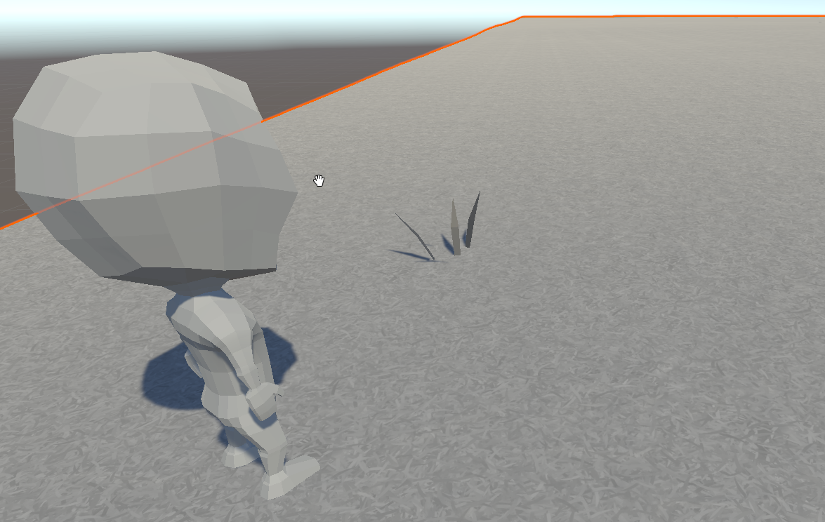
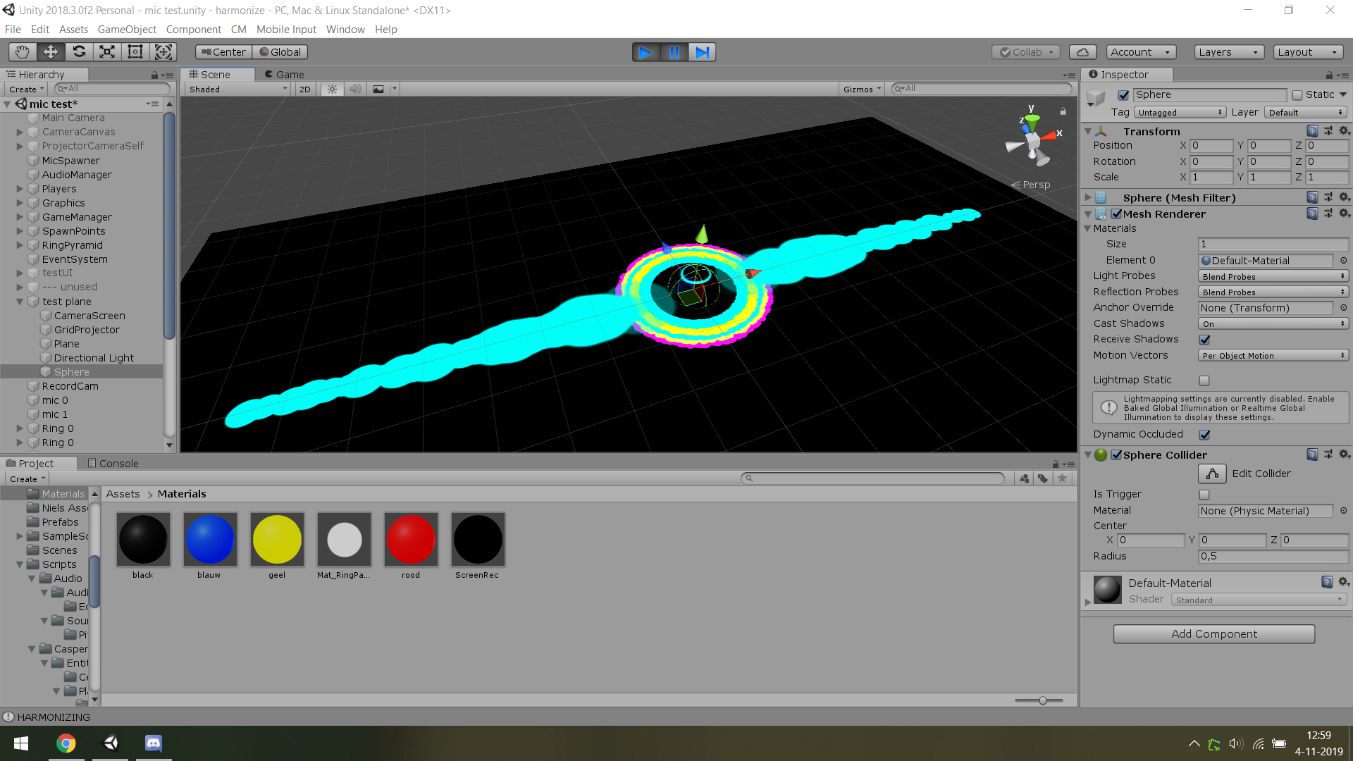
so uhm, i got an odd thing to make imo, basically pitch noise to visual effects, which is close to done. after palytesting last week though we bumped into a problem, the projector is not straight above the 'playfield'. tried multiple things by now, currently have it set up so one camera records the scene, outputs this into a rendertexture which gets projected onto a plane with a sphere on top of it, well atleast it should. when i tried to just create a plane and a sphere the rendertexture got displayed on bot 3d object, so i made the object one in blender but now i cant find my material being displayed onto the merged object i made, any tips/help?
working with 2 3d objects: https://i.imgur.com/UW3AswF.png
not working with the merged object: https://i.imgur.com/YK2wQIc.png & https://i.imgur.com/5XSTXML.png
thanks in regards :-)
not sure if its the shader i have to adjust or something else, if this is the wrong channel please let me know. thought it kinda fits the case
yeah fwidth is the issue as far as I can tell.
https://discordapp.com/channels/489222168727519232/497874081329184799/640866880135102464 ok nvm i found what i needed :)
this is basically what i wanted, my dumb head didnt configure the projector right https://i.imgur.com/aad1Rnb.png
@winter acorn nope. Its book of the dead
Hi all, maybe somebody can help me. I upgrade my project to 2019.3b09 and now I have some trouble with my shaders created with shader graph. I getting these errors now and I don't get why and from where.
@silver bronze Hey, you know how it is when you start thinking about a method, and then you can't stop...well now that I've had some sleep...
The distance to the edge might be what you want, rather than distance from the center. So from the other direction.
The distance to any edge assuming you have a UV that is from 0 to 1, is basically:
intensity = min(min(uv.x, 1-uv.x), min(uv.y, 1-uv.y));
I think. Try it if you're interested. It won't be round though, so depends on what you want. Maybe *2 since you need to scale it, or even use a slider for the scale and saturate the result so you can scale it and "just do edges as gradient".
So intensity = saturate(min(min(uv.x, 1-uv.x), min(uv.y, 1-uv.y)) *scale);
@meager pelican thanks! I’ll try it out once I get home from school, next I think I will try to implement a black-white map texture for intensity
Yeah, that's kind of what I did, but it wasn't for the intensity (which was scaled with a slider), it was for he distortion, but there is also a final mask too which ends up being a 2nd color intensity, so it could be used for that. There were other things too. This stuff gets fun.
I almost published it, but I'd probably only make 50 bucks on it, and then have to support it for 3 years... 😉
@tame skiff what kind of special inputs do you have in the shaders? are there any arrays? if not, try reimporting the shaders
I mean you could just not support it 😉
then it wouldn't sell though
tbh tough, anything that would stop working are builtin stuff which people could probably figure out themselves. Plus, if there is a glitch noticeable enough for someone to catch, it would probably be beneficial to fix for yourself as well
so that's another thing
🤷
@cosmic prairie As I know I did nothing special. Just created a shader with shader graph with subGraphs.
@meager pelican so just a quick review of last night and to make sure that I understand the vert and frag functions, would these comments be correct?:
                // If I understand correctly, vert modifies what the positions and the uv refer to in the texture
                // If I understand correctly, frag modifies which part of the uv the color data is taken from and can modify the color value further
sorry to bug ya 😛
@tame skiff one of the subgraphs mightbbe trying to redefine stuff
But how can I find out which part is causing it.
Normal usage of nodes should not lead to something like this, right?
The error points to a line in UnityInput.hlsl where this is written:
real4 unity_SHAr;
umm I also got an issue, isn't this supposed to work in theory?
it gives a weird result
it should be like this
@silver bronze Sort of. uv's are positions within the texture. So I wouldn't say "positions and uv's". Usually position in a vert() is about vertex location in the model. To be differentiated from uv (texture location mapping).
These things are put into interpolators, and the results are lineally interpolated in 4d, basically.
So then in the frag is where you usually actually READ the color texture at that pixel's uv offset. But in your case, you screw around with it first to distort it.
So in this case, yes, the frag modifies what location it would read from the texture.
lol this works shader graph has the big gay
@silver bronze Basically, the Vert() runs once for each triangle vertex passed to it in a mesh. The Frag runs for each PIXEL that ends up being colored by the triangle.
In the Vert() there's some matrix-magic to get vertex locations in clip space (-1,-1) to (1,1) on your screen. Then there's more magic that happens to map it all into screen space during rasterization.
There's semantics for telling the shader compiler what certain interpolators values are (Like SV_Position) and there's just normal interpolates (texcoord0, texcoord1....)
All the data the Frag() gets comes from that process OR it has to "go get it" like doing a tex2d() call.

Stack Overflow
I am trying to make an endless runner similar to Subway Surfers. I got the perfect textures and models but I can't seem to find or make a toon shader that doesn't flatten my textures since I have
Can anyone help me with this? You could either reply here or in stackoverflow?
Anyone encountered a problem when using DDX and DDY in the Vertex Normal of a shadergraph?
Mostly when getting The object Position further in the graph
Something about Vs_5_0
Okay so I've narrowed it down to the error showing up when using a Position node in Object Space in the Vertex Normal step
do you have a normal node connected to the vertex normal output at all or just position?
there's a known bug already filed that you need to have the vertex normal upstream somewhere for the interpolator to generate, otherwise it will error with unknown subscript normalOS or something similar
I have a Vertex normal node plugged in
I can reproduce the error by plugging in an Position node in Object space with a Vertex Normal plugged in DDX and cross producted with a DDY with the same input
So far I baked the object space info into the Vertex color but it's really not ideal
The nodes don't make any sense I know, but the error itself appears whenever I have a position node Object Space in the vertex position offset
I would love some help with this shader I'm trying to get set up that dynamically makes a drop shadow for the character/sprite that is being used. This uses two things a script and a shader that we have, and ill put them respectively here. The problem is that it is distorting the shadows geometry atm
View of the edited geometry : http://prntscr.com/psm2ne
Shadow Caster Script
using System.Collections.Generic;
using UnityEngine;

public class ShadowCaster : MonoBehaviour
{
    public Vector2 offset = new Vector2(-.1f,-.1f);

    private SpriteRenderer spriteCaster;
    private SpriteRenderer spriteShadow;

    private Transform transCaster;
    private Transform transShadow;

    public Material shadowMaterial;
    public Color shadowColor;
        void Start()
    {
        transCaster = transform;
        transShadow = new GameObject().transform;
        transShadow.parent = transCaster;
        transShadow.gameObject.name = (transCaster.gameObject.name + " Shadow");
        transShadow.localRotation = Quaternion.identity;

        spriteCaster = GetComponent<SpriteRenderer>();
        spriteShadow = transShadow.gameObject.AddComponent<SpriteRenderer>();

        spriteShadow.material = shadowMaterial;
        spriteShadow.color = shadowColor;
        spriteShadow.sortingLayerName = spriteCaster.sortingLayerName;
        spriteShadow.sortingOrder = spriteCaster.sortingOrder - 1;

    }

    // Update is called once per frame
    void LateUpdate()
    {
        transShadow.position = new Vector2(transCaster.position.x + offset.x,transCaster.position.y + offset.y);
        spriteShadow.sprite = spriteCaster.sprite;

    }
}

{
    Properties
    {
        [PerRendererData] _MainTex ("Sprite Texture", 2D) = "white" {}
        _Color ("Tint", Color) = (1,1,1,1)
        _Transparency("Transparency", Range(0.0, 1)) = 0.25
        [MaterialToggle] PixelSnap ("Pixel snap", Float) = 0
    }

    SubShader
    {
        Tags
        {
            "Queue"="Transparent"
            "IgnoreProjector"="True"
            "RenderType"="Transparent"
            "PreviewType"="Plane"
            "CanUseSpriteAtlas"="True"
        }

        Cull Off
        Lighting Off
        ZWrite Off
        Fog { Mode Off }
        Blend SrcAlpha OneMinusSrcAlpha

        Pass
        {
        CGPROGRAM
            #pragma vertex vert
            #pragma fragment frag
            #pragma multi_compile DUMMY PIXELSNAP_ON
            #include "UnityCG.cginc"

            struct appdata_t
            {
                float4 vertex   : POSITION;
                float4 color    : COLOR;
                float2 texcoord : TEXCOORD0;
            };

            struct v2f
            {
                float4 vertex   : SV_POSITION;
                fixed4 color    : COLOR;
                half2 texcoord  : TEXCOORD0;
            };

            fixed4 _Color;
            float _Transparency;
            v2f vert(appdata_t IN)
            {
                v2f OUT;
                OUT.vertex = UnityObjectToClipPos(IN.vertex);
                OUT.texcoord = IN.texcoord;
                OUT.color = IN.color * _Color;
                #ifdef PIXELSNAP_ON
                OUT.vertex = UnityPixelSnap (OUT.vertex);
                #endif

                return OUT;
            }

            sampler2D _MainTex;

            fixed4 frag(v2f IN) : SV_Target
            {
                fixed4 c = tex2D(_MainTex, IN.texcoord);
                c.a = _Transparency;
                c.rgb = IN.color * c.a;
                return c;
            }
        ENDCG
        }
    }
}```im not sure why its modifying the geometry of the sprite and losing the original shape, but ive been looking around and cant find a solution
any help would be appreciated
I was using NVIDIA Nsight to view debugged shader code. I tried to use sources online saying what each part of the code below does, like https://docs.microsoft.com/en-us/windows/win32/direct3dhlsl/dx-graphics-hlsl-sm4-asm, but I just can't comprehend what the heck is going on and how it would look as actual shader code. Could someone please give me a general rundown of what this code is doing and it's relation to normal shader code, along with how to comprehend other ones in the future?
Code (from NVIDIA Nsight):
https://hastebin.com/vigidufaqo.makefile
(this is a unity shader)
@silver bronze That's compiled shader code, takes a lot of concentration for anyone to read and understand 😅
Hey i am trying to add indipandend scale X & Y support for a shader, currently it will only work with _BrushScale, code:
float2 Rotate(float2 p, float degree) {
    float rad = radians(degree);
    float x = p.x * cos(rad) - p.y * sin(rad);
    float y = p.x * sin(rad) + p.y * cos(rad);
    return float2(x, y);
}

float2 CalcBrushUV(float2 mainUV, float2 paintUV, float brushScale, float deg) {
#if UNITY_UV_STARTS_AT_TOP
    return Rotate((mainUV - paintUV) / brushScale, -deg) * 0.5 + 0.5;
#else
    return Rotate((paintUV - mainUV) / brushScale, deg) * 0.5 + 0.5;
#endif
}

float4 frag(v2f i) : SV_TARGET {
    float h = _BrushScale;
    float4 base = SampleTexture(_MainTex, i.uv.xy);
    float4 brushColor = float4(1, 1, 1, 1);

    if (IsPaintRange(i.uv, _PaintUV, h, _BrushRotate)) {
        float2 uv = CalcBrushUV(i.uv, _PaintUV, h, _BrushRotate);
        brushColor = SampleTexture(_Brush, uv.xy);

        return INK_PAINTER_COLOR_BLEND(base, brushColor, _ControlColor);
    }
    return base;
}
How could i do that ?
is there a simple way to get model outline via shader or only option is with custom pipeline that generates normal texture from scene and do some evil magic from that ?
or rather - what is the easiest way to get specific model outline ?

GitHub
Source code for Outline Shader tutorial for Unity. Detects edges in a scene using the depth and normals buffers. - IronWarrior/UnityOutlineShader
will take a look, thx
I just published a asset that allows you to create all sorts of cool outlines and many many more effects in a couple clicks!
https://assetstore.unity.com/packages/vfx/shaders/all-in-1-sprite-shader-156513

All In 1 Sprite Shader is an all in one solution to include cool popular sprite and UI effects to your project in the easiest and fastest way possible.
Interactive Demo :
WebGL Demo Link
Features :
- Stack and combine effects with just 1 click
- Easy to use
- ...
Stack Overflow
I am trying to make an endless runner similar to Subway Surfers. I got the perfect textures and models but I can't seem to find or make a toon shader that doesn't flatten my textures since I have
Can anyone answer my question please? I am really stuck on this and without this shader, my game is useless. :C
I would appreciate someone's help! I 😦
@grand jolt You could try this out https://assetstore.unity.com/packages/vfx/shaders/flat-kit-cel-toon-shading-143368
So I'm trying to adapt the Lens Flare Shader of Fontaine Bleue demo for HDRP to work with Single Pass Instancing, I got the effect to be instanced, the problem is that the calculation for depth and Eye ray are all wrong since it's aiming for the center of the screen. Makes it appear like you're cross eyed.
Anyone has experience in sampling depth for HDRP single pass instanced?
@upper kite I’m asking for help in doing that xd
Like better understanding and visualizing what it does
I've made a fog shader that works in the editor but not in the game environment
I can't seem to find what causes this problem nor any solution online

if anyone could help me with solving this, that'd be greatly apreciated
Cause is probs related to depth buffer in isometric view
I have the depth texture enabled in the pipeline settings (if that is what you mean with depth buffer)
btw
setting the camera to perspective will not solve the problem in the game scene
what is the default color value for normal maps ?
is that 817FFF ?
I'm trying the following:
var tex64Normal = MakeTex( new Color( 129/255, 127/255, 1f, 1f ) );
aka 240/360 Hue, and 50% Sat, 100% Val
Sooo I'd like to add ambient occlusion to a shader. I converted a set of primitive cubes into voxels and they're now rendered as a single mesh, but that means they don't have ambient occlusion and it looks ugly
I have no clue how to do it but I assume it's difficult
Is there a process for upgrading shader graph shaders to URP in 2019.3 or do I have to recreate them?
nevermind it's a bug with the material set to GPU instancing
hello,
I am trying to replace colours, but they seem to add up instead and I'm not sure what I am doing wrong
Lose the +
Using Shader Graph I am trying to get an value to lerp from 0 to 1 repeatedly. I know it must be so simple, and I think I have done it before. But I can't for the life of me remember how.
@echo badger you can use Frac on time, it gives the fractional part of a number, always 0 to 1
@sudden mountain check the clear mode of your camera, try setting to none, it shouldn't be required though
Ah, thanks @uncut karma, works like a charm!
@uncut karma clear flags is missing on my camera, there is only background type where it is supposed to be
heyo, do you think this would be a good place to ask about camera and rendering?
@frozen dagger #archived-hdrp Perhaps?
Hey, how can I create a custom master node with HDRP/URP? I want to have cel-shading on my game but I can't find a good tutorial on this matter.
https://blogs.unity3d.com/pt/2019/07/31/custom-lighting-in-shader-graph-expanding-your-graphs-in-2019/ I already took a look at this, but it doesn't really cast or receive shadows from/into other objects.

Unity Technologies Blog
With the release of Unity Editor 2019.1, the Shader Graph package officially came out of preview! Now, in 2019.2, we’re bringing even more features and fun...
Anyone know where I could get a hold of a high res free snow texture?
It would need to be tileable q.q
I’m googling as we speak
@scenic bough
https://cc0textures.com/list?q=snow
https://texturehaven.com/textures/?o=popular&c=all&s=snow

Get hundreds of PBR materials and textures for free under the Public Domain license.

Ooooooo thanks!!!!
You’re a god(dess) among men
Dam cc0textures is high res
That’s amazing
And it looks like they would all work great for both terrain and snowballs ^-^
I have a flat mesh (all vertex y-coords = 0). In my terrain shader’s vertex program, I lookup a value on a height-map and adjust the vertex.y value based upon that. This works great except for one problem: sometimes the mesh is clipped improperly. I assume it is clipping based upon the flat mesh position, rather than the adjusted position computed in the shader. How can I fix/fudge this?
(This image shows the clipping problem on the left, changing the camera angle slightly.. makes it go away and look like on the right.)
GPU triangle clipping happens AFTER the vertex stage. So it should be using the modified vertex positions. I suppose it's possible Unity didn't sent that section of terrain... or it's just colored black for some odd reason.
@meager pelican that's actually a whole mesh that's not being drawn (we just see, or rather we DONT see, just a bit)
(terrain is made of multiple meshes)
some help to double sided a standard shader in "fade" mode the cull of currently only works for "opaque" mode help pls
@ocean bison Right.
Sounds like bug-land. 😉 What's it look like with no y offset? Does it show on the screen then?
you mean if I turn off the y-offseting in the vertex shader? It WOULD be offscreen if I did that.
OK, so I suspect it's not the GPU culling it, but unity culling it.
(it would be flat.. but have no clipping issue)
I tried the following.. adjusted the shader to SET rather than ADD to the y coordinate.. then in unity.. I offset the mesh's transform.positon.y upwards... (this worked.. kinda )
but after doing this.. I started getting clipping for distance meshes instead!
it also meant I had to do some weird stuff in the shader to ignore the modelmatrix- which I didn't like... don't suppose I can override what unity thinks the mesh bounds are? (or whatever it uses for clipping)
Yeah, I get ya. IDK. No longer really a shader issue. Per se. Maybe someone else will know, or try the terrain forum. Wishing you luck, but you can't be the first one to run across this, so hang in there.
FYI: looks like I fixed it... apparently.. this is WRITEABLE !?! https://docs.unity3d.com/ScriptReference/Mesh-bounds.html
anyone have any idea why I'm getting strange behavior from a plain shader in URP?
the shadows seem too intense, and there's a weird patterning on the front faces
The pattern is related to your projects shadowmap bias settings
Anyone an idea why my transparent PNG Texture on my shader looks all f'ed?
my shader is set to Transparent in both the RenderType and Renderqueue
if I create a new material with the Standard Shader it shows like this with the Opaque Redering Mode...
but it looks fine when I set the standard shader to transparent. But my shader still have the tags for a transparent shader so idk why it's not working
        {
            "Queue" = "Transparent"
            "RenderType" = "Transparent"
        }
did you add a blend mode?
@neat hamlet yes
Blend SrcAlpha OneMinusSrcAlpha
is it unlit or surface?
I'm not entirely sure what you're asking
But I'm writing my own vertex and fragment shaders, so I'm leaning towards unlit? :p
ok, what are you returning in the fragment shader
                float3 dotProduct = 1 - saturate((dot(input.normal, input.viewDir)));
                float fresnel = pow(smoothstep(1 - _FresnelWidth,1.0,dotProduct), _FresnelExponant);

                // Texture
                fixed3 main = tex2D(_BarrierTexture,input.uv);
                //return fixed4(main, 1.0f);

                // Add a Trim Color
                float4 TrimColor = _BarrierColor * fresnel * _TrimIntensity;

                // Multiply texture with barrier color and add TrimColor to it
                main =  main * _BarrierColor + TrimColor;


                return fixed4(main, fresnel);
that's my entire fragment shader
youre not using the alpha of your texture at all there
if you want the alpha to work you gotta use a vector4 as the tex2D result
you're a god
changing that fixed3 to a fixed4 indeed worked
stupid me. Thank you @neat hamlet
no problem 😄
quick question about shader graph: Can you blend two master nodes? I'm looking to blend a Alpha cutout with a Alpha transparancy to get some of the model cutout, but have soft/blurred edges.
That's not really how it works
@plucky bone yeah I figured out. I'm currently using the genesis hair shader which is doing something similar to what I'm talking about (I think), where the cutoff turns into transparancy instead of removing the pixels completely, making the sorting fine, while giving a soft finish for hair. I want something similar in hdrp, but am just learning how to use it.
Biggest ever noob to unity, started yesterday. Playing around with shaders. Is there a way to trigger a shader when the character dies. So far I've only figured how to directly apply shaders
You probably want a shader that does the effect you're looking for based on a toggle/percentage
Or you can change the whole material
Oh so when the character dies, run a line in c# to toggle the effect?
you can set global shaderparameters via
Shader.SetGlobalFloat , Shader.SetGlobalVector, etc @elder garnet
tyvm
you set .setfloat on a single material too, probably best to use propertyblocks if you wanna do it on multiple things with the same shader at different times
why do i get random color noise when blitting a texture via Graphics ?
RenderTexture SetupRenderTexture(Texture baseTex, int propertyID, Material material)
{
    var rt = new RenderTexture(
        baseTex.width,
        baseTex.height, 0,
        RenderTextureFormat.ARGB32,
        RenderTextureReadWrite.Linear);

    Graphics.Blit(baseTex, rt);
    rt.filterMode = baseTex.filterMode;
    material.SetTexture(propertyID, rt);
    return rt;
}
is that something to do with the screen backbuffer ?
i have a portal scene set up with stencil masks, but I cant figure out how to allow objects to be draw in front of the portal that are not masked to the portal
Hey so it looks like "MetaVertexPosition" changed in the universal render pipeline to require 5 inputs, any ideas on what the last input might be?
Looks like a second set of lightmap UVs, is there a good default value to send in?
does anyone know of a blur shader that is efficient on mobile?
@sly breach I may be wrong here, but I thing it's because you're using incompatible formats. From what I see, you're blitting from a normal map (probably dxtNM) to a ARGB32 texture.
@amber saffron interesting, i will check it out
Hey, @amber saffron i can't seem to find dxtNM in RenderTextureFormat
my imported texture is type of "normal" in the inspector
That's what I said 🙂 Try using a non sRGB default texture
The format is written at the bottom of the preview
Normal Map :
And forcing a RGBA format :
thanks i see now
but i kinda need to keep it as it is
this is my problem
it should look the same after blitting
but when i hit play it will change it in play mode
to this :
but when i set it to sRGB it will break the normal map
@amber saffron
Oh, got it. It's not a normal map at the base, but a generate normal map within the importer ...
So switching to default texture gives you something totally different, and is kind of expected
Hum, strangely, I don't have your issue
Here's my code :
{
    public Texture2D refTexture;

    // Start is called before the first frame update
    void Start()
    {
        RenderTextureDescriptor rtDesc = new RenderTextureDescriptor();
        rtDesc.width = rtDesc.height = 256;
        rtDesc.volumeDepth = 1;
        rtDesc.dimension = TextureDimension.Tex2D;
        rtDesc.depthBufferBits = 0;
        rtDesc.msaaSamples = 1;
        rtDesc.graphicsFormat = GraphicsFormat.R32G32B32A32_SFloat;

        var rt = new RenderTexture(rtDesc);

        Graphics.Blit(refTexture, rt);

        GetComponent<Renderer>().material.SetTexture("_UnlitColorMap", rt);
    }
}```We're getting a bit out of subject here, as it's not purely shader related
hey, is there any way to get linear fog start & end
instead of whatever this is: –1/(end-start), end/(end-start))
which is located in unity_FogParams
Super noob at shaders. I'm currently trying to make a hair shader. Is there any easy way to "blur" the edges when using cutoff?
The term you're searching for is probably "anti aliasing"
Either as a post process
Or in MSAA, you can use alpha to coverage : https://docs.unity3d.com/Manual/SL-Blend.html
Uhh I think I have a very severe problem
Basically, UNITY_SHOULD_SAMPLE_SH from UnityCG.cginc always returns false
Because it is supposed to be an instantly pluggable thing I consider this a problem. I do not undefine it anywhere in my shaders and libraries
Hey. Does anyone know a way to make a Sprite render like a Mesh in relation to other meshs? My case is a little complicated, I'm using a shader to make an object invisible and only receive shadow but the problem is if I put a sprite behind it the sprite disappears (when in relation to the sprite it's like the invisible object is opaque) and I need the sprite to be behind the shadow like it was receiving it. I know it would be possible to turn the sprites into quads but since it would be complicated because of tilemaps I'm looking for other options. I really appreciate any help.
I basically am looking for a way to make a sprite be rendered even if inside or behind an opaque object but not to be on the front of the object
Hello, I have a problem with Post Processing in Unity. I added a Post-P. Volume and selected my P.P.-Profile. Now I've got a blackscreen, but when I turn the Weight of the Volume to 0, the blackscreen vanishes. Every object related to this is in a extra Post Processing Layer.
Any ideas how to fix this?
Shader error in 'Hidden/PostProcessing/Uber': failed to open source file: '../StdLib.hlsl' at line 21 (on d3d11)
but I can run the game
Is there a good way to mark a resolved issue in issue tracker to active again?
Is there a reason I can't name a texture "_BaseMap" in shader graph? I get this error:
Shader error in 'Unlit Master': redefinition of '_BaseMap' at line 61 (on d3d11)
uncheck the exposed checkbox
@stone sandal shader still doesn't wanna compile 🤔
The shader is dead-simple, but lemme know if something looks wrong
*Using LWRP 6.9.2
then you probably need to use a different reference name, there are some that are used internally that will cause errors like that
but i don't remember off the top of my head what they are
ah that's too bad i wanted to follow the naming convention of the standard lwrp shaders, but i guess it's not a big deal. thanks 👍
I love Shadergraph :D
@amber saffron i think i found the issue, graphics blit will not copy mip mappings
why is there 3 input about the vertices and not 1 about the position mon my pbr master node ? im using the urp
(x,y,z)?
i dont think so
i think that xyz are for vertex position
Is your question about normals and tangents?
i want to use an offset and tilling node for my water shader but when i try to plug in the only thing moving is the primitive
Your graph doesn't show how you've implemented that
all you need to do is offset the UVs that you feed into the sampler
ok i got it for the tilling
seems that it work only with a 2d texture if i want to "move it "(/loop it)
but i cant do int for my group of node who are plugged in the albedo but i still dont know why i have " vertex position, vertex normal , vertex tangent " np
thanks you ^^'
has anyone used Chromakey shader before?
Oh dear URP devs. Can you please not break basic functionality - turns out the builtin _Time shader variable is set different between shadow pass and forward pass. How on earth does that happen...
(this is a single object which uses a _Time based vertex offset. Note that the shadow moves different, and that the object sometimes casts shadows onto itself.)
(Case 1197515)
I'm having a strange artifact when an emissive UI element is drawn over a very emissive object, any idea why this is happening?
on the right side the bottom line becomes black when on top of the cube
Anyone here can work with HDRP?
@dull dew i'm working with URP
can you use VFX graph for one-shot effects like explosions or camera flashes? or is it more intended for persistent effects like a campfire or a lake?
realtime
and just that single dir light
yup
is that the default unity tree shader? maybe you need to update something in it to HDRP?
sorry I'll just be guessing, i haven't done too much HD, mostly LW
HDLit
why it takes like 2 seconds to undo in shader graph even if its just simple node move🤔
Hey, I need some help with some assets I'm trying to get from github. When I pull and then add the files to unity, the assets and materials are all pink, but I have both the 3d model and material
What pipeline are you using, and was it the same one that the asset used?
I’m wondering if there’s something like lattice in unity?
A lattice... deformer? You're going to have to be more specific
https://github.com/keenanwoodall/Deform is an option
Will check it out thanks! @vocal narwhal 🙂
How would one go about making a shader to replace parts of an image (the white parts) with team coloring? I found some examples but i dont quite understand why they arent working
you make an RGB mask and multiply team colors with one of the RGB channels
i am unclear as to what that means
bool IsPaintRange(float2 mainUV, float2 paintUV, float brushScale, float deg) {

    float3 p = float3(mainUV, 0);

    float3 v1 = float3(Rotate(float2(-brushScale, brushScale), deg) + paintUV, 0);
    float3 v2 = float3(Rotate(float2(-brushScale, -brushScale), deg) + paintUV, 0);
    float3 v3 = float3(Rotate(float2(brushScale, -brushScale), deg) + paintUV, 0);
    float3 v4 = float3(Rotate(float2(brushScale, brushScale), deg) + paintUV, 0);

    return ExistPointInTriangle(p, v1, v2, v3) || ExistPointInTriangle(p, v1, v3, v4);
}
// ...
float2 Rotate(float2 p, float degree) {
    float rad = radians(degree);
    float x = p.x * cos(rad) - p.y * sin(rad);
    float y = p.x * sin(rad) + p.y * cos(rad);
    return float2(x, y);
}
Why are the sign values are flipping sign ( + and - ) in the first function for the rushScale variable ?
Trying to extend this to support X & Y
Edit :: oh nvm, i solved it
Anyone that has an background-blur shader for UGUI laying around, preferably one that works in camera render mode (not just overlay)?
Hey, every time I create a new property in shadergraph it crashes and I have to restart the shader graph window each time. Does anyone else have this problem as well or knows a solution for it?
Update your LWRP/URP version
It's a known issue that was active for months and only recently fixed
It worked😄 Thank you so much, you just saved me a lot of restarting🙌
has anyone got experience with VR and Commandbuffers?
So, I have an HDRP shader with a depth pass, and no matter what I do it doesn't seem to get rendered in the depth pass.
it's set to tag DepthOnly, named correctly, etc..
just doesn't get rendered.. ever..
@main blade Sure, it's not much different from using them for non-VR.
Hey there shader guru's. I'm working out the best way to achieve this...
(Forgive the crude example pic)
I want the ability to have n number of points displayed on an object with a variable radius and colour. I would like to avoid setting information in vertex colours (but have a feeling it may be the way to do it...) and certainly don't want it to be via a texture.
One way I was thinking was having multiple world points passed into the shader, then determining the radius from there to set the falloff - however that would require having a set amount of points as a max (I suppose I could have variants of the shader for say max10, max20 etc...)
Does anyone have any thoughts on how to achieve this kind of effect?
You could use an array for the points and loop through the length
Can you pass in an array of values to the shader tho? I was under the impression you couldn't
here's a guide of something similar https://www.alanzucconi.com/2016/01/27/arrays-shaders-heatmaps-in-unity3d/
@south matrix Is the object always a sphere?
no it will be a mesh, I have a prototype using hard coded positions, I think I'll just do variants on x many points and using the according variant when needed
Im a complete novice when it comes to shaders, ive read several things about how to do this involving RGB masks, and using the red channel of a shader to colorize it. The texture im trying to give "team coloring" to is just a random exerp of a larger texture, with the areas im wanting to colorize, changed to grayscale for reference. What do i need to do with the shader, or what do i need to do to the image itself to get this to work?
So this is the desired result, just with several other points added.
Something inside me feels I can achieve this with signed distance fields or something, but I'm not that smart 😄
@real basin - Hey thanks - how good is this guy!
It is quite similar to what I had thought I needed to do, so I think I'll continue down this path :)
Thanks for your input
There's a number of things you can do depending on your exact requirements and expectations. Generally, as AZ noted in his article, using for loops to look through arrays is slow.
Another way is to generate several (?5? ?20?) textures with random circle data, and then assign them with material property blocks. You could give each object a random offset to rotate the texture. Would be fast, depending on how often you'd have to regenerate them, and if you need it repeatable. You could even do color replacement, and give each object random colors using the same texture.
It all depends.
Thanks @meager pelican - I understand the drawback of loops, I think I'll continue with the variants using 10points/15points/20points etc - this will be the only object on screen when this effect is rendered so I think the performance hit is acceptable.
I did think about doing some kind of texture projection - however for my needs I would need to rebuild it each time this view is used as the radius of the point will change over time.
Thanks for your input tho, it has definitely given me some options to consider. 👌
loops in shaders aren't too bad if the length of the loop is the same for every vertex/fragment and the contents of the loop aren't anything super expensive. the compiler unrolls it to be basically the same if you wrote out the steps yourself
I need to render an object only when it intersects with another specific object...basically like this. Is this possible, and would anyone be able to point me in the right direction?
If anyone has any ideas/pointers, please tag me
I'm not strong in shaders but I think you need to compare the distance of the vertex of the object to other geometry. Somewhat like ambient occlusion I guess. You would need to pass geometry data( was that the zbuffer?) data to your shader and use it to check if you should render certain vertex(or maybe texel/pixel?).
@night sandal
Yeah I'm thinking some sort of combo of z buffer and stencil might do the trick but I have no idea which combo
And trying randomly hasn't gotten me far lol
I donno if texels have screen position data(they probably do), but if they do, you can just compare your texels vs buffered texel' depth difference to see if you should render it.
I might be wrong doe xD
Well thanks for the input, regardless

This is a tutorial on creating an intersection shader using Shader Graph in Unity 2019 alpha which uses the depth scene node Buy my LWRP Material Pack to sup...
This might help you.
Oh, that's using shader graph... But I'm pretty sure you'll find an article for coding it yourself if you Google.
Thanks, even if it's shader graph I might be able to get something from the compiled code
Oh hmm the shader in that video just relies on depth, so it highlights everywhere near the intersection, but it doesn't give you the actual intersection
for example this is a stencil shader where you can only see the red cube when looking 'through' the plane
but how would you make it that the white 'floor' plane here is invisible when looking 'through the plane'?
but visible outside of it
so like this, that the yellow part is just transparent
Yeah that's basically what I need...I'm not sure if it's possible. I'm thinking I might need 2 objects, one to handle the part that's behind the main object, and a second to handle the part that's in front
But I'm not sure
Although in my case it's even more complicated...in those pictures the plane is beneath the cube, meaning the entire cube is rendered in front. In my case the cube would be intersecting the plane, and I need to cut a hole in the plane and only render the cube in places where the hole is
Again, if anyone's got ideas, please tag me
@night sandal There's an example at the very bottom of this docs page which might help : https://docs.unity3d.com/Manual/SL-Stencil.html
You can punch the hole by drawing it first with a depth write. BUT what it draws.....you need to draw something to fill in, right? A hole in a plane/terrain just looks like a bad-mesh, unless you want to compute some type of volumetric. Not sure what you really want.
This might give some ideas:
https://www.youtube.com/watch?v=cHhxs12ZfSQ
Although he's using meshes not terrains.@night sandal
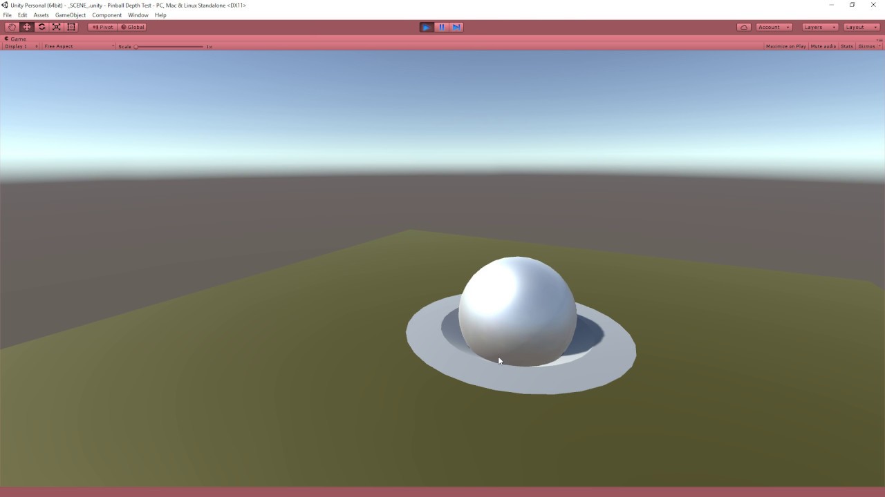
Make sure to SUBSCRIBE so you don't miss a video! Download the complete project: http://quill18.com/unity_tutorials/PinballDepthTest.zip Also, please feel fr...
My blend settings must be wrong because it blends differently between a mesh and the standard unity cube
what settings for my blending should I use to make them equal? currently using Blend One OneMinusSrcAlpha
You can try SrcAlpha OneMinusSrcAlpha.
Or just put this:
        [Enum(UnityEngine.Rendering.BlendMode)] _DstBlend("Destination Blend", Float) = 1```

in your properties and this:
```            Blend [_SrcBlend] [_DstBlend]```
in your subshader

But additive blending can to blow out colors particularly with lighter colors.  Try swapping the colors on the objects once.

The One OneMunusSrcAlpha is for premultiplied alpha.@meager pelican Thx for the propery/subshader thing - that let's me test it at runtime
unfortunately all of the options end up somewhat blowing out the colors a bit
it's not ideal but if I'll have to live with that. What I'm trynna do is create an alpha channel to blend textures etc with
thanks though
Is there a way to get instant compute buffer readback on dx12 or Vulkan in Unity?
Seems like they still wait, like on DX11
Drawing is basically queued. So there's little realtime intervention from C#. There are some event-functions that you can use, like "OnPostRender()" or some such. But that may not be what you want. Maybe check into compute shader doing the C# work instead? Depends on what you're doing.
IDK if you can pull it off with command buffers. Normally you wouldn't want to read back too much.....
Ok but that wasn't the question
Hello everyone, stuck with a problem, any opinion will be really useful (pls write the @cyan plume so I get the notification).
I have this shader:
It's a custom shader with alpha and emission
It also allow me to move the vertex trying to emulate the waves
however when I have a sphere behind the emission stops working
In the zone "1" the emission works
but in the "2" it does not
Thank you
whats the best way to extend a shader so I can add a grayscale effect? is it most efficient just to copy the shader source and modify the line I need, that way I don't need any more passes, etc?
@tired narwhal So you want to be able to toggle the grayscale effect in the material editor or through script?
well yes, I already have shaders I do that with, but now I use some third party shaders like CTS and while I could edit those shaders, I'd rather not, I'm just looking to see if there's a better way to "extend" an existing shader
No, there's not. So duplicating is the best option.
thought so. in that case, how can I properly point an #include statement to another assets folder?
relative paths I guess?
seems to work in the editor, no clue if it'll work in a build though
It'll work. Before the shader is compiled, the #include is replaced by whatever code is being included
anyone have any idea why my post processing is showing in the scene view, but not the game view?
i'm using Universal Render Pipeline with a single global volume with a bloom override. do I need to put anything on the camera like with PPv2?
the shaders I am expecting bloom from were created in shader graph
is there a way to invert the black in this shader? im trying to achieve a blue and white noise rather than a blue and black noise..
(1 - noise) * desiredcolor(white)
How do you make a shader like.... not do anything to the original image, if that makes sense?
@versed apex Use an unlit shader set to be transparent. Plug the "scene color" node to the "color" input of the master node.
if I have water like this, with scrolling foam
how can I make it so that the foam would follow the direction of the river?
so not all in one direction but kind of bending
with the river
Edit the UV of the water so that it matches the direction of the flow on one axis
okay will try that!
So, I'm trying to make a shader for HDRP using the Shader Graph. Is there any way to use structured buffers for input. And is there any way to tell the shader which properties are global and which are instanced?
I think you can use structured buffers when you use a custom function node with a HLSL file
I've tried doing custom function nodes with my own HLSL files. But declaring variables etc outside the scope of functions doesnt seem to expose them any where =/ Or I'm completely missing something
does anyone know how to do this in LWRP ?
polycount
Thanks for the reply man!
I've done a lot of research but still haven't found an effective solution, specially on URP
why does my hdrp shader not update even though it's properly updating in the asset viewer / inspector etc?
@errant ocean perhaps you should check this one out if you haven't already. not sure if it works in LWRP though...
https://assetstore.unity.com/detail/tools/terrain/microsplat-terrain-blending-97364

The Terrain Blending module for MicroSplat allows you to smoothly blend objects with the terrain
Once enabled, easily blend objects with the terrain. No need to use custom shaders, generate custom meshes, or fiddle with complex settings - just add a component to your ob...
is it not possible to use material.SetFloat on start/alive?
been watching a Shader Graph tutorial series and very commonly the instructor adds his shaded mesh via a particle system rather than dropping the mesh in the scene. what are the advantages of doing it that way? is it just to allow easy doubling/copying?
additionally, are you able to use Shader Graph materials on VFX Graph output?
Soon
ohh like it's in dev? is that a 2020 thing?
I'm not sure tough, but 19.3
cool cool thank you for the info
Hello people!
I want to randomize the offset of my shader texture to display different parts of the texture on my objects randomly.
This is what I got:
The transparent texture (.png)
My shader graph
My scene view
As you can see there is no randomization at all, is there a 'quick way' to do this?
btw: I played a bit with the random min/max values, tried 0 to 1, 0 to 2 without success.
It's not randomized because you always give it the same seed, so it always gets the same result.
So, I just need to set different seeds?
Do you want each mesh to get a random offset?
I have a mesh made out of single triangles and I want to randomize it for each face.
Do you want a new random offset every frame?
No, just once.
And this is not something you could just do from script? Shaders don't really have a concept of a first frame or doing something just once at the start
I think I need to explain a bit more:
I have a point cloud project based on this github project https://github.com/leon196/PointCloudExporter
It loads point cloud data into unity and builds a mesh with single vertices, no edges and faces. Then a shader creates triangles to put textures on it. It is a written shader, but I dont know how it works exactly.
The point is: I want to display letters as textures instead of circles (default in the project). But when I just put the texture on it the letters are all displayed as a whole for each triangle. My idea now is to create a tiling for the texture and random offset so each triangle has a random (maybe repeating) letter.

GitHub
Contribute to leon196/PointCloudExporter development by creating an account on GitHub.
Sorry, that escalated quickly... 🙈
Quick question : can i extend / override the standard shader source code to include my own surf function ?
Using shadergraph, which node do I need to use to do a translation onto a "Simple Noise", so that it scrolls sideways
@left basin scrolling of textures happens with adding uv offsets over time. You can also factor in tiling if you wish.
Figure out the nodes on your own, I don't graph, I type. ;)
But you can multiply the offset (as a scroll rate) by _Time.y (or see unity doco on the _Time shader variable for other values).
Why setting a _Value inside the CGPROGRAM won't change the value in Properties{..} ?
@willow basin hash the vertex position in the vertex shader to get a pseudo-random value per triangle. Use that hash as an UV offset (turn the 1D hash into a 2D UV by wrapping).
also, it's pretty fancy @-ting you, good job with the username
@gilded lichen thank you, I try it! But what do you mean with hash? I can't find any node like this. I'm new to this whole shader topic.
@willow basin sth like this, in your case randomness distribution doesn't really matter so something simple like this would suffice https://stackoverflow.com/a/4275343
aaargh any node genius here? need to recreat the highlights on the shoulders with the same behaviour

While the quality of photo-realistic real-time graphics in games is advancing daily to near feature-film quality, Arc System Works' RED team took a completel...
tried a bunch of vector math, worked out semi good
Hey guys, I'm trying to follow https://thomasmountainborn.com/2016/05/25/materialpropertyblocks/ I have a shader with parameters I need to change per object. Here is my code: http://prntscr.com/px7tlr Here are my shader parameters: http://prntscr.com/px7tqf I figure I should try to read the value before trying to change it to make sure I have a good reference on it, but I don't seem to. Debug.Log is just outputting 0, when Tiling.x is 2


You need to change your Reference fields in the shadergraph
so that they're called names that you can refer to via the property block appropriately
The name that appears in the oval is just the one that appears in the inspector. The Reference field is the one that the shader is actually using
Yeah I tried using that one in code, same issue. Changed it to _Tiling, also same issue D:
It's weird because I'm not getting a null reference, so it seems to be getting it, just not reading it correctly or somethign
Also, I'm not sure if you can get the value if you haven't previously set the property block? Try setting instead of getting and see if that works out
Oh, since it's new... good call
Oh sweet! That got it rolling! Thank you very much
Bleh, changing it via script changes other instances though
Weird, moving it to update out of awake fixes that
I'll take it. Thanks again
Hah okay. Well, if you do have issues there are lots of talented people who frequent this channel, and #archived-hdrp can also be a good place for things you might think are LWRP-specific
Oh that's a good point. Thanks again
how can I make a shader in shader graph that supports this kind of texture blending?
That's polybrush right ?
You need to use the vertex color in shader graph for blending