#archived-shaders
1 messages · Page 120 of 1
@grizzled owl I don't know if it helps but there's a slightly different version in the pinned comments
command buffers seem perfect @real basin thank you so much
@vocal narwhal this one?
@grizzled owl this is how I read depth in LWRP currently
I remember getting it to work in HDRP as well but I lost the files
I remember somebody saying 'eye space' is different between the SRP's
@regal stag Thank you! Yes, I was finally able to get the result. Damn, it really was the issue of setting the material to transparent...
@vocal narwhal and @devout quarry Thank you for your input too!
I was hesitant to enable transparency, because it introduces artefacts on my end
Well, now I know depth texture requires the material to be transparent 🙏
These are the artefacts I get, when enabling transparency
When the mesh is overlayed by itself it goes bananas
Depth fade is working as it should, as you can see on the right side of the picture. But on the left side are the random clipping artefacts
Were you guys ever experiencing the same issues with transparent shaders?
As I understand it is caused by the order in which the polygons are drawn... But can't seem to find if there is a solution to this right now.
Hey I'm having trouble with post processing stack v2 Bloom a d custom shader. Is thu
Is the right channel to ask?
this or #💥┃post-processing
what SRP are you using?
LWRP / HDRP , version?
or built-in renderer?
I'm just using the standard render pipeline
The sphere on the right is the standard shader
Sphere on the right is my shader
Both shaders emmisve values are the same
I can't figure out why the standard shader looks different to my own
Is this a Pp, GI or shader issue?
@grizzled owl is it multiple meshes or a single mesh? or are there multiple elements in a single mesh?
@light basin i think the reason it is different is the standard shader applies exp2(-emissiveColor.rgb); when HDR is off
it only seems to do that in deferred
aside from that it looks like nothing special happens to emission in the standard shader
the standard shader also uses HDR Color picked for emission color, so the intensity value in the picker could cause differences too...
It's still strange to me, shaders for materials are created using ShaderLab language and include CG code, right? Why? Post Processing effects use HSLS, same as compute shaders.
hey wassup
anyone got any tips on how to make an underwater effect/shader for water ? I managed to get some results with that depth buffer trick, but it only works for surfaces
@rich echo Depends on what is your intention pal. If you wanna make an image effect, simply distort the _MainTex with a sine wave. Add couple of bubbles with animation to UI, add fog to environment, set a cookie which project caustics texture and you are good to go!
I wanted to make something more realistic, like some sort of fog volume
Does anyone know if the normal lwrp Unlit shader supports per instance colouring with MaterialPropertyBlock? Just want to check if it is my code that is wrong or the shader doesn't support it
Okay it does appear to be the shader after some tests.
Any recommendations for an unlit shader that supports custom per instance colours and GPU instancing?
Thank you for the input @uncut karma when you say "hdr is off" do you mean in the quality settings / camera, both are on and I get the above results
Unless there is a difference in using [HDR] attribute and drawing the color property manually (via custom editor), I can't see the color picker being a problem, I set the color to 255,0,0 intensity 10, on both materials
Hey! Have anyone ever tried making tri-planar shader with texture atlas?
I can't seem to get it to work
@peak sail Instanced color works with the LWRP unlit shader, at least with 2019.1.7.f1
Guessing you used the wrong property name (they changed it for some ungodly reason, so now it is "_BaseColor" not "_Color"). That's what burned me the first time.
@meager pelican It wasn't working for me. I was getting some really weird results. I edited the shader to include:
UNITY_INSTANCING_BUFFER_START(Props)
        UNITY_DEFINE_INSTANCED_PROP(float4, _InstanceColor)
UNITY_INSTANCING_BUFFER_END(Props)
As well as changing the instances of _BaseColor to use _InstanceColor and now it seems to work. I have no idea if that was a good idea though.
That's one way. You'll have to maintain your customization of their standard unlit shader forever, each time it changes., though 😦 I'd either make a new copy of the shader, or better, use the standard one but differently. Here, this will work with the standard shader (you'll have to customize it to your needs, of course, IDK what you need to do in your entire project, so think about it). Hope it works for you:
#define USING_LWRP
using UnityEngine;

// This class would be in a separate file, and the USING_LWRP define above would be set in project properties or something
public static class ShaderPropIDs {
#if (USING_LWRP)
    public static int _Color = Shader.PropertyToID("_BaseColor");
#else
    public static int _Color = Shader.PropertyToID("_Color");
#endif

    // ...
}

[RequireComponent(typeof(Renderer))]
[ExecuteInEditMode]
public class SetInstanceColor : MonoBehaviour {
    public Color instanceColor;

    private Renderer myRend = null;
    private static MaterialPropertyBlock myMpb = null;

    void Awake() {
        SetObjMaterialProperties();
    }

    private void OnValidate() { // only in editor
        SetObjMaterialProperties();
    }

    // public callable, so set public instanceColor (and any other attributes), then call this.  Or use a setter on instanceColor to call this.
    public void SetObjMaterialProperties() {
        if (myRend == null) myRend = gameObject.GetComponent<Renderer>();  // you could move these to Awake if you wish, depending on needs
        if (myMpb == null) myMpb = new MaterialPropertyBlock();

        myMpb?.SetColor(ShaderPropIDs._Color, instanceColor);
        myRend?.SetPropertyBlock(myMpb);
    }
}```^^ So you could put that on a few quads or whatevers and set the colors and check the profiler and prove to yourself that it works for an unlit material. (ran out of room, 2000 char limit)
You shouldn't need to customize their shader, as it already supports MPB. Maybe you could ask about MPB in the general-code area, and/or define what "weird results" are. The MPB needs to be set for all custom properties at once, as it will overwrite all custom properties, as I understand it. So if you have several properties, you'd want to set them all, then call SetPropertyBlock. That's also why it is static, so it can be reused and you don't have to allocate a bunch of them, but there's a thousand ways to organize it so you'll have to think about your use case. That's just an example.
Thank you very much for your help I do appreciate it. I probably should have mentioned that I am drawing all of these shapes using the Graphics.DrawMeshInstanced method which is potentially a cause of the issue as it uses the SetVectorArray potentially why it requires the UNITY_INSTANCE_BUFFER_START stuff manually. I don't know if that makes anything different with respect to support for per instance shading. It seemed to me like each batched call was otherwise getting the same property (which appears to happen due to grouping of invalid properties). I know nothing about shaders though so this is all just my best guess.
So yeah, your code works but that uses a single MPB per instance whereas I'm using the ID version that uses 1 MPB per 1000 or so. Sorry for not specifying that.
Well, my original point is that the stock shader does support both instancing and MPB.
So you used SetVectorArray on the MPB for the colors of each of your 1000 instances...set up the 1000 transforms....and called Graphics.DrawMeshInstanced and it didn't work the first time? Interesting....
is there still no support for authoring custom shaders in anything other than Shader Graph even now that LWRP is out of preview? does Shader Graph still not support stencil buffers?
Yeah, @peak sail, if you're doing that it looks like instancing needs those per-instance properties in the shader. I wouldn't modify their stock shader though...I'd make a copy, call it something else, and go from there. In the standard pipeline, when they discuss instancing, they do the same thing in their example , FWIW. See https://docs.unity3d.com/Manual/GPUInstancing.html for an example of instancing color that will work in standard pipeline with DrawMeshInstanced. Looks like they only instance transforms by default.
I tried DrawMeshInstanced in LWP, and all the transforms worked but the instance color didn't, just like you said. I suspect that it won't work in Standard either without having a custom shader using the UNITY-INSTANCE_BUFFER_START stuff.
FWIW, I think you can still use _BaseColor as a name, and only copy that/those files that you explicitly need to modify. Sorry I can't be of more help, the last time I messed with this stuff it was the procedural variety (DrawMeshIndexedIndirect) and had a custom shader anyway.

is there any way to pass a buffer to a shader while still being able to use shader graph?
to allow me to use Graphics.DrawInstancedIndirect while not losing the ability to use the shader graph?
I did make a copy of course. Thanks for the info. I did try to use the default _BaseColor but it gave an error saying it was a re-declare but if I removed the original declaration it said not defined.
In any case, I really appreciate the help and all the effort you put in to help me out. Thank you very much.
Is there any info on the status on async compute shaders? The official documentation says that they are only supported on PS4:
https://docs.unity3d.com/ScriptReference/SystemInfo-supportsAsyncCompute.html
However, these forum posts seem to indicate that DX12 should have support for them as well:
https://forum.unity.com/threads/async-compute-support-for-more-platforms.583540/
However, when I tried DX12, the supportsAsyncCompute bool still happened to return false, but then log messages seemed to indicate that they could be running asynchronously. I'm not an expert on these things by any means, so any help in understanding what the status might be is really appreciated.
I couldn't find anything referring to Vulkan support either, but I presume that they should work there as well?
Unity Forum
Hi,
Hope I'm posting in the correct forum, wasn't sure if I should post here or in "Betas & Experimental Features".
2017.3 added support for Async...
@peak sail yeah, they can't BOTH be _BaseColor. But you can keep the "master" base color. So it could be used as a tint-for-all, for example. You'd just look up the instance value and multiply _BaseColor * the instance color. Maybe as a master tone value. The point is that you don't have to rename _BaseColor, but you'll need a different name for your instance colors. 😃
I'm trying to make systematic shaders for 2D sprites. So shaders I can slap on many different sprite for different events. Possibly having multiple at once. I'm really struggling to even start using shader graph and I really can't find much that's helping. At this point I don't even know if I should be using shader graph for this. Any advice or resources because I've got nothing. 😅
I'm only trying to make some simple shaders by the way. Give a sprite a colour outline or make its size change for a bit. Thought this would be a nice intoduction to shaders but so far it's been the hardest thing I've done.
Well, I can confirm that the SystemInfo.supportsAsyncCompute bool returns false for DX12 and Vulcan for LWRP and false for DX12 Standard Pipeline on my system too. But IDK if it actually works or not if one tries it. My card says it is supported for DX12 and Vulcan in the manufacturer's site. Haven't tried actually doing it though.
A thought: A graphics debugger platform might help you watch what's happening per frame and across frames. Both AMD and NVIDIA have developer tools for profiling what is running on various threads, etc. if unity's tools aren't sufficient.
Sorry can't help much, I hope Unity Tech chimes in, it's a good question.
Cheers, thanks for checking as well! I tried debugging the frame in RenderDoc but wasn't really sure what to look for as the output isn't as well labelled as it is for DX11 yet. Will have a closer look sometime soon. 😃
has anyone made a sky shader with shader graph?
would anyone know what this thing is, its like a marker where you put it next to a color and then it becomes that color and draws, like the eye drop tool on photoshop, it matches the color?
like it becomes the color it touches
an example would be changing the material color when said object touches another color, so red makes it red, blue makes it blue
Does anybody know how to create an Update shader for CustomRenderTexture in HDRP?
I can't find any info about it
like a chameleon skin
@north karma this is a pretty niche feat in general, it's possible that many haven't even realized it's missing from HDRP
I think unlit shaders used to work for LWRP in past (not sure if it's still the case) so it's possible that this only affects HDRP
(I mean, unlit for built-in renderer)
and since it's hackweek, we might not get hold of Unity staff now who could answer this question
Oh, you answered in ASE discord too 🙂
Yeah, I think you're right, no many people using CustomRenderTexrures, but you can create really cool VFX with it.
yeah, I also posted on forums, nothing that will help you though 😃
I'm actually looking at UnityCustomRenderTexture.cginc here
@lapis gulch you could just check for collision, read the material and set the material
I believe it's possible to port this but it would require similar changes on HDRP shader / would require proper shader code knowledge from HDRP shaders
the whole cginc code is like 215 lines total
would have been nice hackweek project for some :p
and yeah, it's super useful for effects that need any feedback loop
I guess you could do similar things with compute but that's also yet another thing that's not easy to approach on HDRP
@devout quarry its for VRChat so i cant use a script
I have a question
When creating clouds like these
Do you think I would be better off creating with noise nodes?
Or drawing them as textures?
And if with textures, are there some clever tricks to make sure they all look pretty random?
You could always create textures with noise so they're random... 😋
hey guys im kind of confused about understanding a outline shader and im lost on the terms they are using
I'm trying to set a render textures color format to RGHalf but the color format popup on the render textures import settings doesn't have it. The popup appears to be showing options from the UnityEngine.Experimental.Rendering.GraphicsFormatenum. Do render textures not use UnityEngine.RenderTextureFormat in HDRP?
I think most formats are migrating to GraphicsFormat
You'll want one of the R16 formats for half. (Sorry I said 8 bit initially)
I dabble
Haha
if i wanna smooth my bake smoothly my normals how would i do so
would i first take the normal data and then apply a smoothing?
i mean i have done this but then...
hmm idk im going to figure out myself
Ya I'm not sure. Depends on what you are trying to do
im trying to smooth the normals then inverse them to finally make an outline by making them (bigger)
But can't i just use a function that creates a color after the offset of my object and a designed postion?
nah... that would only work for 2D
@grand jolt you would generally do that in your 3D package the assets were created in, you could duplicate the .fbx/.dae/.whatever in Unity and change the normals to Calculated and then adjust the Smoothing Angle but you won't have fine grained control over the results
what's the easiest way to access a float array or StructuredBuffer from within Shader Graph? it still seems to be missing a lot of basic features
i see
@tardy spire rghalf is r16g16_sfloat
could also use _snorm i think
@wild edge you might be able to use a custom node
will try, thanks
would love to know if anyone succeeds in accessing a StructuredBuffer @Rustin i haven't had luck
Deleted the old thing because I know what the issue is but I am unsure how to solve it.
It seems like the default value I am declaring in the shader is not being used as the default value for the instance props.
This is declared in Properties:
_MainTexUV("Texture UV", Vector) = (1, 1, 0, 0)
And this is declared in the Pass:
UNITY_INSTANCING_BUFFER_START(Props)
    UNITY_DEFINE_INSTANCED_PROP(half4, _MainTexUV)
UNITY_INSTANCING_BUFFER_END(Props)
The problem is that it appears to be using a default value of (1, 1, 1, 1) for each instance (if not overridden) this is breaking the shader as I need the default for UVs to be (1, 1, 0, 0) but I can't work out or find any information on how to do that and the value declared in Properties doesn't seem to do anything.
Surface shader, or custom vert/frag? If custom, did you remember to add:
#pragma multi_compile_instancing
and is instancing enabled on the material?
Yeah instancing is all working fine (tested the functionality by hardcoding values)
Custom working theory is that the custom editor is causing the problems.
Well, sight unseen, IDK. But the latest Unity version (IDK what unity version & OS you're using) DX12 API works well enough under Windows to run Visual Studio shader/graphics debugger. You can watch the values change and see what is trashing them, or if the shader code is wrong, you'll see expected values coming in, then getting messed up by the shader.... I assume you can trace through the custom editor too. Just a thought. They have a tutorial on debugging DX12 shaders in their docs if you haven't done it already. I know that's not much help....sorry. Maybe someone else has experienced this. Wishing you luck. 😃
Oh neat I didn't realise there was a shader debugger. Thanks for the tip 😃
Well, there is, if you can get it to work.... 😄
Yep, was absolutely the editor. How weird.
hey guys. Does anyone know how to make an invisibility cloak shader? It's kinda like the depth shader from vuforia, but the problem is, with vuforia's shader, if I put the shader on a cube, I can't see anything behind the cube. I want to be able to make invisible only the objects I put inside the cube
so I want to be able to see everything around the cube, just not inside it
The way to make something invisible is to not draw it...
(Not sure what you're after). So when you "put it inside the cube/box"....turn off the renderer. Take it out, turn on the renderer.
for example
add a cube and a sphere in an empty scene. Scale the sphere so it fits inside the cube. Now, I want the cube to be invisible. But if I zoom in and go inside the cube, I see the sphere
pretty much like the invisible cloak from harry potter
and I don't want it to affect the surroundings. I can achieve this with the depth mask from vuforia, but then if I can't see what's behind the cube, for example. I just want to make invisible what's inside it, and the cube itself
@rugged moon Hmm, I think you could solve it in a way by doing a pass on cube to write mask with front cull, then a pass with the object that checks depth in front and mask =1 and write depth to texture, then a pass on cube with cull back and check depth and mask, and then finally decide to draw by checking the mask ^:D probably an easier way.
Can you separate things into layers? Like background vs stuff-that-would-be-made-invisible.
You can do with with a multi-pass type of thing. There's an example from Brackey's, but I think you also want layers. The Brackeys version is a "see through shadow" type of thing, but you could alter it maybe.
I don't think I want with layers. Because the idea is that the object would slowly come out of the invisibility cloak
it would slowly appear
The cloak would be in that layer too.
ok, could you point me a tutorial or something on how to do it? If there's an asset on the asset store that works too. Actually, I was hoping there was already something like this ready to use. I don't understand a thing about shaders, just want this as soon as possible. So if there's a simple tutorial or asset to buy, great
What pipeline are you using?
Anyway, see if this makes sense to you: But it's not exactly what you want.
This is LWRP and it's pretty close to "no code", maybe you can alter what it renders to suit your needs.
https://www.youtube.com/watch?v=szsWx9IQVDI
Let's learn how to render characters behind other objects using Scriptable Render Passes! This video is sponsored by Unity ● Download Project: https://ole.un...
standard pipeline
well thanks for the pointers. If you feel like doing it for me and charge a reasonable price, I'll buy it from the asset store
I think @hushed urchin has the right idea, with using a stencil and the cloak would write the stencil but not draw itself, and the other materials would clip to that stencil so you would "see through the cloak" to the background maybe with a slight distortion. BUT it would have to not update depth so things behind it would still write...or maybe just draw that layer later.
The thing is...writing an actual cloak gets more complex due to cloth materials...cloth motion. You started describing a simple cube, but with cloth, it has to "flow" and that's a highly specialist asset that tends to be of ?limited use?...I wouldn't sell 1000 of them, for example. :(
Maybe someone will contract for you and do it custom. There's a site for unity contractors, but IDK what it would cost. Short of that, check the unity learn site tutorials and also the documentation on stencil and depth buffers in surface shaders which aren't all that bad, might be work experimenting with one of their examples for fun. 😃
Is there a trick to avoid having "compiling preview shaders" loading bar on every node I add?
@rugged moon will this work? https://assetstore.unity.com/packages/tools/particles-effects/invisibility-cloaking-fx-100326

An invisibility cloaking special effect, making an object or character semi-transparent while distorting the background behind them.
A shader and material are included that can be applied to any Unity object, plus a custom script and detailed instructions to have any charac...
nope, I saw that. I don't want distortion. And really, I don't want the object itself to have the ability to become invisible, but to have an invisible field
invisibility field
doesn't need to be complex, don't need cloth materials to work with this. Just 3d objects...mesh+texture

GitHub
Added SpeedTree shader graph node to allow for wind effects in shader graph shaders (both HDRP and LWRP)
cool
this is how it should have been from the start
hi guys...
I'd like some advice on a little project I'm doing...
I'm trying to recreate this animation: (please view in browser to see the animated effect)

it's going pretty well...

i still gotta dial in the exact color gradient, sizes of the sphere and clamping but the logic is there with standard shader
all i'm missing is the edge detail
time to learn shadergraph!
so...

this gives me a cube with broken out colors i can script
i replaced the square input texture with a rectangle node.
i'm using a co-routine to set the gradient outline on each cube, it's murdering the frame rate
also it's crude, as i can only color a whole cubes outline, causing a stepping in the gradient
I'd like to adjust the shader to apply a gradient based on worldspace X Z position co-ordinates to the outline of all the cubes.
and also offset that gradient over time, also on the X Z axis
can you guys point me in the right direction for this, indicate the names of nodes i should be playing with. thanks a lot.
If you want to bring back framerate... it's going to be hard
But it's possible
You have to somehow save pivot for each vertex of an cube (every 24 verts of each cube will have the same pivot), I don't know how to exactly do that.
Next you can apply some matrix transformation for each vertex.
For colors, insides can be made with simple math.
Outline can me made by overlying some noise over edges using lookup texture.
well i got the outline, what's killing the framerate is running 256 co-routines to color them crudely on time.deltatime
i'd like to drop the script and color the outlines using nodes to define a gradient, and multiply the output color by the outline node
I haven't used the shader graph at all but I have to assume there's a world position node. what you want to do should be pretty simple
if you're doing it in a coroutine, i at least hope you're using property blocks and not creating tons of instances
by colors I meant doing them without coroutines
I'm trying to render particles with positive and negative colors to a render texture for displacement but the render texture appears to be clamped to positive values.
The shader used by the particle system should be outputting colors darker than black, and the render texture I'm using is R16G16_SFLOAT so I'm not sure what could be preventing the camera from rendering negative values. Any ideas? I'm new to using render textures so it may be something basic I'm missing
I would do something like red channel for positive numbers, green channel for negative numbers
Unfortunately I need a 2d displacement vector, not just a value. It seems to have been done here https://drive.google.com/file/d/1E_vjNknY1w4dnMadBQsZfh86-J4jd5O0/view so I'm not sure what I'm doing incorrectly
or make it all positive then subtract .5 and multiply by 2 so it'd be on a -1 to 1 scale
I actually tried remapping the range, but the background of the render texture ended up being a problem. If it's black, most of the texture will remap to a displacement vector pointing down and to the left. If it's grey, which should remap to a displacement vector of (0,0), the additive particles are too bright since they are being added on top of the grey color
Not sure if it's relevant but I am using HDRP and the writeup I linked above is using the legacy render pipeline. I'd think if any pipeline would support negative values being rendered to render textures it'd be hdrp tho
@tardy spire -
I'm trying to render particles with positive and negative colors to a render texture for displacement but the render texture appears to be clamped to positive values. The shader used by the particle system should be outputting colors darker than black, and the render texture I'm using is R16G16_SFLOAT so I'm not sure what could be preventing the camera from rendering negative values. Any ideas? I'm new to using render textures so it may be something basic I'm missing
A float has a lot of precision. Just encode it 0-1.0 and then use .5 as your zero point. np = (theValue * 2. -1.) would give you -1.0 to 1.0
Does that work?
Ooops - @real basin already said that..... sorry.
I think color space needs to be set to linear for negative values to work, but hdrp should force to linear anyway. If you really want it to work that way you could test it outside of hdrp to see if it’s interfering in some way
@meager pelican I tried remapping the range but the background of the render presented an issue. My third comment elaborates on the issue. I'll do a test on the legacy pipeline and see if it works.
I don't want to stomp on Dezufnocosem's posts, and I already said 'sorry' for repeating what he said, so you can he can discuss I guess.
However, you might want to clarify your comment because if you have a displacement texture, you shouldn't be rendering particles into it...you use it as data input to render the particles + data onto the screen or into another texture......so maybe I'm all confused as to what you're doing.
What type of displacement is it? Color displacement or vertex or what? You talk about grey and additive colors but also sounded like you were displacing vertex positions. So I'm confused.
@meager pelican The render texture is used to add forces to particles. The particles sample a pixel from the render texture based on their normalized xy world position and add the rgb to their velocity. The render texture is generated from a camera rendering a separate, hidden particle system used solely for the displacement texture. The shader used on that hidden particle system is never meant to be seen but is colored in a way that should create interesting displacement if the rbg is used as a change in velocity. This is a common technique used for stuff like simple water ripples and snow deformation, but in those cases you just need a scalar, not a vector. The need of a vector is what is proving a problem since a vector that can't have negative channels isn't very useful. The only reason I assumed this was even possible was bc of the article I linked which does appear to be rendering negative values into a render texture via a particle system.
OK, thanks. Sorry for the question. Did you try his code sample, and did it work for you? Here's a thread on the topic of negatives in RT's too: https://forum.unity.com/threads/how-to-write-negative-values-to-render-textures.536963/
Looks to me like you can use signed RG values. Where does the assumption that a "vector is the problem" come from? R would be one component, G the next component, etc. Should work with signed values.
Buuuut....back to what we said...if you can't get negative values to work for your vector, just don't render negative values. Remap them. IDK how a background would be a problem if the resulting values are 0 -> 1.0 You'll have to map that to your offsets in the other shader when you draw the destination stuffis, and make it -1.0 -> 1.0
As for additive blending on the effect that is generating the offset texture...you said it's additive. Whatyagonnado? Could switch blend modes. Or truncate values or lerp remapping them. There's no way I can tell with your use case, but it should work if you put all the pieces in place with the right values in the right order.
IDK, I'm probably not helping, but you might want to check assumptions because it should support negative values and it should support vectors (multi-colors) that are negatives. It's the storage-type that's important...signed half or full float, and you said you're using R16G16 sfloat so I would think it is signed values. So unless HDRP is messing you up somewhere, it SHOULD work! IDK.
Unity Forum
I want to output the normals of a scene, using a shader I created, to a render texture. Then I want to convert it to an EXR file so I can read it with...
The only other thing I can think of is to use the debugging tools and look at the render texture and follow a pixel and watch what values change and if you want to go so far as to use a shader debugger, there's a few options depending on your hardware...but...there's a write up in the unity doco about debugging shaders in DX12, and I've gotten it to work with a recent version of unity and their experimental DX12 API. Also since I have an AMD card, I use AMD tools and that also works and lets me investigate using low-level debugging.
I appreciate the response @meager pelican I'll try and pursue the stuff you mentioned. I think I have to have additive particles so two overlapping particles will result in -1-1=-2 instead of 0-0=0 where they're both negative, but I think youve given me a lot to work with beyond that specific problem. Thanks 👍
Yeah, I took a look at it and he's outputting -1 -> 1 in his particle shader and mentioned using additive. But if you're doing that you'd end up with a -2 -> 2 range in the end, with 0->4 in the interim. So adding 0 to 0 would end up mapping to -2. The thing is, what if you have THREE that overlap? So you'd have to decide how to remap and how to truncate overages before remapping. All it really is, is a shift.
Anyway, the negatives should work, and you shouldn't have to remap anything. Let us know what you find out, eh? If there's a problem with negatives in RT's in HDRP, I think people would want to know.
theres not a problem with signed RTs
are the particles unlit? make sure that shader isnt clamping to 0
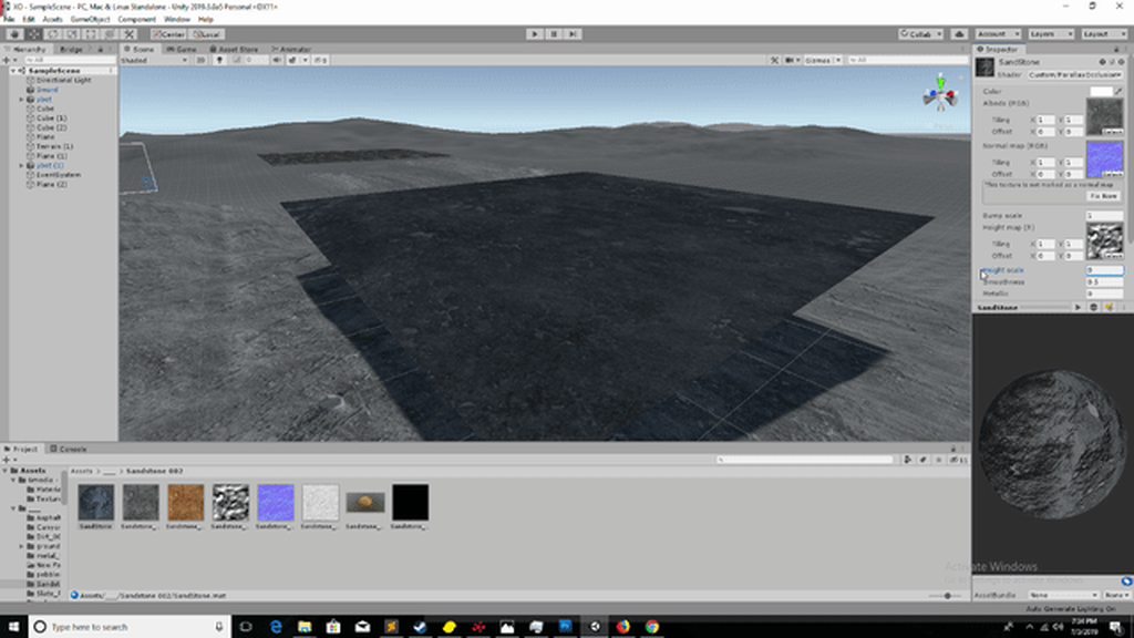
Am I missing something critically basic on my world space shader. Texture is super stretched..
He should also double-check that it is supported on his hardware, or whatever hardware his shader is running on....https://docs.unity3d.com/ScriptReference/SystemInfo.SupportsRenderTextureFormat.html and have a fallback, but I assume that's not his current problem.
@proven sundial Tried https://docs.unity3d.com/Packages/com.unity.shadergraph@5.3/manual/Sampler-State-Node.html
????????
I solved the issue through some trial and error. But I'm worried that I'm basically making a triplanar with this split. And I want it to be as cheap as possible..
I have two objects that use the same material. One object is placed physically in front of the other (2D so the Z of one is closer to the camera). The problem is that the object behind is drawing in front of the other object.
When I set the Surface Type to Opaque this stops happening but when it is transparent the problem persists.
What are some things that might be causing this that I can try to fix it? I have tried everything I can think of but nothing has worked. I would really appreciate any help as this has been a hair pulling experience haha.
Some other things I have noticed: Transparent with blending mode additive and multiply also seems to "work"
@meager pelican I made a new project and tried offsetting vertices with a render texture on the legacy pipeline and it worked. So the problem has to be stemming from HDRP, Shader Graph or VFX Graph since everything else I did was the same. In regard to the number of overlapping particles affecting the range of values, I'm ok with it. If two positive parts overlap I want the effect to be stronger and if a positive and negative part overlap I want the effect to cancel out. I don't need the colors remapped to a -1 to 1 range since I'm just adding the rbg as a force. The weird thing is, the values definitely aren't clamped to a 0 -> 1 range. I can make the values go way higher than 1 but I can't go below zero.
Here's some tests I did to make sure my shader was outputting negative values. In the first gif I'm outputting a constant -10 as the color
In the second I'm outputting a constant 1
I don't really expect anyone to have an answer but I figured I'd give an update to say it's possible negative values don't work with HDRP. I doubt it; I'm probably doing something wrong, but at this point I have no idea what it could be 🤷
that's bizarre, is HDR enabled?
hdr should allow negative numbers
but without hdr idk why you can go above 1
Yea hdr is enabled cuz I can go above (and bloom is working)
weeird
how are the colors being interpretted? maybe the negative values are going through adn you're interpretting them in some way that cancels values below zero
very cool effect btw
Thank you @bleak zinc . The way the colors are applied as a change in velocity is pretty straightforward. I just get the particles position in screenspace and sample the render texture based on that "uv". I add the rgb to the velocity
darn that looks fine to me
could the sampleTexture2D possibly be doing a clamp for you?
¯_(ツ)_/¯
yea i have no idea. it could really be anything at this point 😦
make ambient light or global illumination darker, they control the brightness of unlit areas
Lower ambient light, add light probes, bake light map with environment objects marked as static @lyric girder
OK, so if it works in SRP we know for dang sure (even though we "knew" anyway) that it isn't hardware related. And that the hardware supports that texture format and stores negative values.
I'd check the shader source and/or maybe hand-write a custom vert/frag, bypassing shader graph, and I'd bet it would work too. So something in shader graph's routines is clamping it to > 0, best guess.
That's where the debuggers can help. There's good doco on setting that up with VS or PIX or something, you have to use DX12 experimental. Then when you figure out where the value is being trashed by stepping through the code, you can file a report. :2c:
Or just ask in their forum and see if they bite.
P.S. Neat demo, with screen-space collisions, or is that the velocity change?
I'll look into handwriting a shader and if that doesn't work i'll see if i have time to whip out a debugger. the project is for a party which is tomorrow so i may just have to cut my losses. and yea it's just a change in velocity, no ss collisions as the collision block is throwing errors when i try and send it a custom depth buffer
@tardy spire I've been doing some render texture stuff with negatives in LWRP, I've just thrown it into a new HDRP project to see if I could get it working. I too saw it was seemingly removing negative values, until I disabled the "Postprocess" tickbox under the Rendering tab on the Custom Frame Settings overrides on the camera that is rendering to the RT.
Bless you @regal stag you are my savior I literally never would have figured that out
@tardy spire No problem! Glad it helped 😃
So..... it defaults to having post processing on in HDRP, buried in the options, and it burned both of you on the RT camera? lol. I mean...I mean...oh man! I never would have guessed it was being post processed. 😉
It's only "funny" if it's not your problem...but then it's hilarious. If it's your problem...you want to throw the monitor through the window after the 1000th time it doesn't work...
Good work Cyan. 😃
haha for real that was a doozy of a problem
Is there an official documentation somewhere for the shadergraph and its nodes?
@ionic mantle check the pinned message
uh, duh, I keep forgetting that feature exist haha, thanks :)
Daaaamn thats alot of info! Great, dont know what I was doing with my life til now but shadergraph is all i need now, and coffee
for quick shader debugging without VS or Pix renderdoc.org is great, unity has builtin support
I have some bare resources for renderdoc integration pinned in this channel 👍
I'm trying to optimize out some conditional branching in a compute shader. I'm simply trying to detect if a pixel is on the edge of a square texture2D. I was doing this like so:
'if (id.x == 0 || id.y == 0 || id.x == (texRes - 1) || id.y == (texRes - 1))'
I've replace it with step() functions and it works, but it isn't clear that it's any faster
microsoft docs say that step uses (x >= y) ? 1 : 0
so am i actually just adding more conditional branching?
@errant tide it's a backtick to post code (three for a block)
thanks!

I ported NoiseBall to HDRP. This shows how to use DrawProcedural on HDRP. https://t.co/Sb7FVp788M https://t.co/gSA5dtoMah
Likes
235
Is it "normal" that the ShaderGraph Gradient node creates a few syntax errors in LWRP?
It works ok for me
How can I use the new Custom Function Node ? I tried updating both ShaderGraph and CoreRP to last versions, but it caused a bunch of errors...
?
just install latest HDRP / LWRP
don't install SG or core separately at all
they need to be same version as the HDRP / LWRP but they will also automatically get installed when you install HDRP/LWRP as they are set as dependencies
if you install manually mismatching versions, you'll definitely get errros
@rich echo
ok thx gonna try that
is 6.7.1 latest possible?
I see on github they are already on 7.x
I'm on Unity 2019.3a
master is 7.x
there's no package released for it
6.8.0 is latest release but it's not on regular registry
HDRP shader supporting SSS needs to support metal as well so we can have the same texture cover both organic and metal properties. I understand SSS itself isn't physically correct with metalness, but we do need to have the same texture sheet cover both types of material
Any advice?
Otherwise it's a painful process of splitting up a mesh just to do that.
Think of a cyborg for example?
I can't think any case where I wouldn't want to put another material for the metal parts if there's totally different shading needed for it
this is why we have separate hair and soon eye shaders as well
if you need SSS, you usually don't care if you need few extra drawcalls for it
it's going to cost extra anyway
So you'd use some unused channel to support a mask that would define what part is sub-surface scattered and what part is metallic? Or vert attributes. Then have metallic maps/setting too.
I don't know a lot about signed distance fields, but could they be used for boolean operations? Like if you generated an sdf for a cube and a sphere could you subtract the sphere from the cube and then draw the result with a raymarcher? Idk if any of that makes sense, but I'm trying to brainstorm the best way to do real-time boolean ops in Unity.
There are youtube examples of exactly that using raymarching and SDF on the net. I've seen them, don't have the link. 😦 But "could you", sure!
As to "best way" (shrugs)
Good to know. Thanks. I'm curious what the difference between using an sdf and just storing voxel/density data would be. Are there any advantage you can think one would have over the other?
They're totally different. The SDF is a mathematical representation of a surface. No mesh. Often merged from several calcs. It doesn't exist at all except in shader math. It's rather slow, really, due to all the ray marching but you can do cool stuff. Lemme see if I can find an old video ...I may have saved a link.
When referring to an sdf I was thinking of generating one based off of a mesh and storing the result in a 3d render texture, not operating directly off of the mathematical representation. At that point how would it differ from voxelizing a mesh and storing the result in a 3d render texture?
IDK, probably wouldn't differ much. The idea behind SDF is to have a math function that returns a signed-distance to surface. Hence the name.
Here's the lecture I was thinking of: https://www.youtube.com/watch?v=s8nFqwOho-s
But there's a gazillion sources on the net if you google "SDF Raymarching Unity"

Good Signed Distance Functions define geometry by providing a semantic description that is very close to the essence of what the shape actually is - but that...
I understand the obnoxious push back on "you don't need metal cos it's not physically correct on the same material" since I'd say the same thing, however it's rather impractical in practise, splitting things up like that when a channel on the mask map can achieve that fine. I'll have to assume it's simply an optimisation for something that's already slow (ie not an optimisation)
Thanks @meager pelican I'll definitely check this out. This is all good info to put in my mental toolbox 👍
@tardy spire vixens are essentially Boolean in nature a cell is either empty or full / on or off. SDF provides a distance value to the nearest surface for a given position. You can store the distance values in a volume. XRA has a github project that can convert mesh to SDF volume, I’ve been messing around with it. I’ll post a link as soon as my window machine finishes updating 😢
Lol vixens = voxels - good old auto-complete
@tardy spire XRA SDF from mesh at https://github.com/xraxra/SDFr
my version - https://github.com/noisecrime/SDFr ( adding some new features and tests )
a;so a few years ago Unity hack week made this SDF tool but was never released - you can see CSG modelling - https://www.youtube.com/watch?v=M3-TdTkScOU

GitHub
a signed distance field baker for Unity. Contribute to xraxra/SDFr development by creating an account on GitHub.

GitHub
a signed distance field baker for Unity. Contribute to noisecrime/SDFr development by creating an account on GitHub.

Unity3D HackWeek 2016 project Signed distance fields rendering in Unity3D. Distance function is authored via a node based editor. Music: Journey by Jan Margu...
Thanks @plucky anvil I'll check this stuff out!
The other thing, @tardy spire is that in a modern GPU internal math is often orders of magnitude faster than texture lookups, like for your 3D voxels. Just food for thought. You may need a texture lookup to represent the arbitrary data. I mean, look at TMP for example. All depends on use case.
Good to know, thanks
I really loved the custom function node, I can simplify node noodles a lot
Hey guys, anyone know why Graphics.DrawMeshInstanced not writign to _CameraDepthTexture?
figured it out
vert/frag shaders don't write to depth buffer unless there's a shadow pass
they write to the main camera's depth buffer but they don't write to _CameraDepthTexture
basically same thing i'm just being pedantic sorry 😅
It writes to the depth buffer if you tell it to write to the depth texture AND if there's a depth buffer. The geometry pass writes to the depth texture in deferred, in forward...it depends I guess. For transparent they DON'T write to depth (because it's transparent).
https://answers.unity.com/questions/1385782/commandbuffer-cant-get-depth-buffer-in-forward-ren.html
Unity is the ultimate game development platform. Use Unity to build high-quality 3D and 2D games, deploy them across mobile, desktop, VR/AR, consoles or the Web, and connect with loyal and enthusiastic players and customers.
yeah i meant that like
they zwrite and ztest
but not to separate texture
_cameradepthtexture and depth buffer are different things right? ive been using them to mean separate things
It depends on the hardware and forward vs deferred rendering, some cards have their own hardware depth buffer, otherwise it's a render texture. They call it "native depth buffer". Sometimes the hardware has its own zbuff but you can't read it, it can be used for early z testing, as I understand it. Other times you can read it, or have unity generate an actual texture and do depth writes, sometimes with another pass.
I think. My head hurts. ;)
Here: https://docs.unity3d.com/Manual/SL-CameraDepthTexture.html
Depth textures can come directly from the actual depth buffer, or be rendered in a separate pass, depending on the rendering path used and the hardware. Typically when using Deferred Shading or Legacy Deferred Lighting rendering paths, the depth textures come “for free” since they are a product of the G-buffer rendering anyway.
Bottom line is that I think what happened with Yukihira is that the shadow pass forced the camera to have a depth buffer/texture active so he got the result he needed. But you don't HAVE to do shadows to have a depth-whatever. 😉
can someone pls give/make me a transparent panorama shader?(same panorama shader, but transparent as skybox)
How are skyboxes transparent?
Anyway, maybe google "HDRI Skybox"
hm, i want to make a sphere (normals turned inner )and use as a skybox(with the normal skybox Panorama shader).
then i make multiple a bit smaler spheres and want render some textures on it, but transparent.
so in the end i see the skybox and the transparent textures from the other spheres.
i hope you can understand what i mean :/
Called a "sky dome". As far as the "other spheres" you'd want to incorporate that into the main sky-dome shader, I think. Some people use particle systems to render things like clouds or whatnot, but I don't usually suggest that. Anyway, maybe someone will want to write one or you can google tutorials or examples on the net.
HDRI is not the thing i want.
Well, it's panoramic...so....guessing.
thx for the help @meager pelican , yeah something like skydome goes in the right direction, i have now to fight with Stero 360 Panorama Pictures, place them correct and make the "Overlay"
if i use a normal transparent shader(Parrticels or Standart) the picture on the Sphere is not correct and have a wierd form
Do any of you all have any tips on how I can make fur in HDRP Shader Graph? I can't for the life of me figure out how to convert from code to the Shader Graph... The fur shader is quite basic - not very big at all. Just not sure how to do a multi-pass shader in Graph with a Vertex and Fragment shader. I know fur is possible I've seen it done - In that Sherman short film on Unity blog... It's like fur is the darkest evil art in the Shader world lol.. I know it can get complex dealing with filmic fur, but a simple Shell shader should be easy to do in Graph. I'm not used to node based editors and this is probably where I'm finding my issue at.
you can't do multipass shaders with SG afaik
and when it comes to sherman, that's somehing else
wish that was a realtime feat as it would be awesome but it was nothing like that 😄
You don't need multipass to do fur, you can raymarch it instead, but that would be really clunky to do in a shader graph.
Thanks for the replies everyone.... @fervent tinsel Now is a Shell Shader something I could do in a Custom Node Function? Or can this do be done with Amplify Shader Editor you think? Or is this simply something locked into HDRP that you just can't do?......... @desert pumice Honestly I'm not too worried about clunkiness if it can at least look decent in the end.... Is there any places that give examples of ray marching in Shader Graph that you know of?
I have no idea what shell shader requires, never done it
you can run your own hlsl functions with custom function node but you can't really control them to run on vertex shaders
Dang... Hope this becomes available when out of preview.
LWRP and SG are already out of preview, but I doubt HDRP getting out of preview would have anything new for this
we can pretty much see already what first "full" HDRP will look like on the github
there are far more important things missing too
like ability to use tessellation on SG
That is true
Kink3d or sparajoy could probably give you better answers but I'm not tagging them here on sunday, better just wait for them to pop online here and then ask
they both work at Unity on SG
I wonder if using a bunch of planes for fur would look similarly as good.
Oh nice, didn't know that
yeah, hence trying to not bug them too much, just love to have them around here when you actually want to ask something more indepth
Totally understand that one.
Kinda wonder if the Ray Marching idea above would look okay if I figured it out.
Some graphs have a raymarching node which would make it easier. Without that it would be thousands of nodes. The basic idea is like parallax occlusion mapping, but instead of a height field you raymarch if hairs are there or not and draw skin if not. You can then apply physics and density like parameters right in the shader. Not that different than the shell technique except no extra triangles.
Do you think the effect would look at least look similar as the Shell technique?....... I did have an idea though.... Manually draw the shells via C# code doing DrawMeshInstanced. Create my layers that way and adjust the values I'd like..... I did do a small test doing that manually by hand with using the standard LIT shader and it actually looked as I'd expect lowering the alpha value the higher it went and it actually had a nice blended blur, just didn't have the nice fur look as I didn't do that stuff in the shader yet... Then I thought - well that's cool and all, but that will go back to a problem dealing with Animation. I don't think it would be very good to have layers and layers and have them all have rigged, unless if I use ECS and it's performant, otherwise no point in that method.
So ive made a water shader & in the editor it looks fine, however, when it comes to the game view it becomes patchy and gross.

any help?
@grand jolt ECS won't help you there. You don't need to have easy layer rigged. If you want to use the shell approach, you can manually draw the extra layers and move the vertices out in the direction of the normal by a small amount for each layer.. Each layer can just have parameters set for it's offset, etc..
Just a question,
how can i make like a water foaming system, that when the plane has an object inside of it, it haas foam around that object?
on my website I have some tutorials
Alexander Ameye
this is for shader graph though
and I'm updating the tutorials so might be a bit outdated

Same water + surface foam! Next is refraction and trochoidal waves, after that I'm going to drop some animals in this water. 🐬 https://t.co/85FXcgNSDO
this is the effect I'm getting
how can i make like a water foaming system, that when the plane has an object inside of it, it haas foam around that object?
@devout quarry you only need one channel for depth
I dunno if that's internally channel packed thing, you'd expect grayscale buffer for that
either way, just get the red channel out
okay thank you!
Hey guys, I'm making an underwater game and I'm currently trying to create a caustics effect (the light refraction at the bottom of a pool). I've been using shader graph, but I can't use emission because then the effect won't apply shadows. I also can't use a light cookie because (for some strange reason) they aren't supported in LWRP. I'm pretty lost at this point. Any help would be greatly appreciated!!!
Can anyone explain this sentence to me? "Now that you have all 3 channels in stored in 2 Texture2D, you can convert them either through a shader". Basically Im trying to convert a YUV image to RBG and store it in a texture 2D
@livid hatch Could make a shader that has two Albedo's. overlay both Albedo's and then offset the 2nd Alebdo during runtime.... This might work for you.
@wide scarab - my translation would be "Now that you have all 3 channels stored in a Texture2D, you can now convert them through a shader"
Ive been looking into that, but everything ive seen has been through the editor and gameobjects. I currently have the two texture2ds and found a shader that converts them to RGB, but I havent found any good sources that explain how to generate a new texture2d through the application of a shader.
with the code for this custom function (hlsl)
I get the following error
but I do not understand at all why I'm getting them
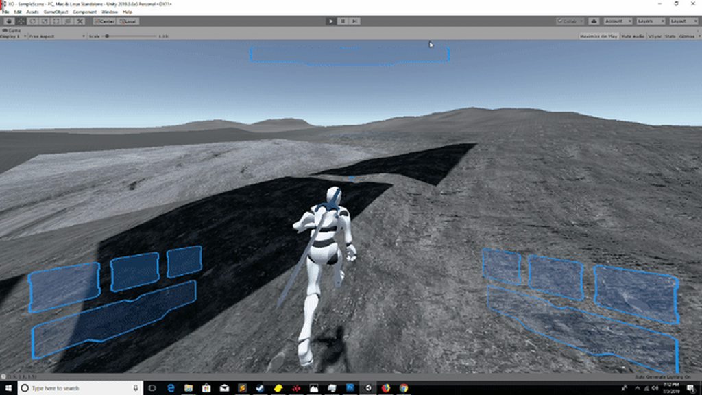
So having a problem with my flat terrain poly shader
The light and pixeling is the correct look, the dark and smooth is not.
it only happens on the terrain slice using the flat shader material
anyone else know what this problem is? If I get to close or too far then it does the dark broken area.
nvm resolved it was my base map distance
I'm using LWRP and need to fade an object from 100% transparent to 0%, but transparent materials show these awful artefacts. Any ideas?
The typical way to do that (though it has its own caveats) is to render that object twice - first pass you render only the depth, no color, second pass you render the color and do depth testing/blending etc, and make sure the ZTest is LessEqual (or GreaterEqual? I forget)
In LWRP this is less easy than it used to be as you can't just have a "multi-pass" shader with ShaderGraph. You need to actually create separate render passes using a custom render data thing to do it
I think you can maybe hand-write a shader that will do it but docs for that are a bit on the non-existent side currently
Basically this https://forum.unity.com/threads/transparent-depth-shader-good-for-ghosts.149511/ but LWRP-ified

Unity Forum
So one of the things you will encounter when rendering complex meshs' using standard transparent rendering is that they depth test against the scene,...
@tardy hazel This gives me something to work with! Many thanks 😄
@grand jolt you could use shells and drive the animations with baked textures/buffer for the skin weights in shadergraph
Thank you @rotund tusk .. Perhaps I'll get to that skill level with HDRP one day, got a lot going on right now, assuming once it's in production mode there will be a bit more learning information out there... I'll keep messing around with it, just seems like everything is 1000 times harder at times, perhaps it's simply just me loving the standard workflow and being lazy hahahahaah.
hader error in 'Lightweight Render Pipeline/Ghost': Unexpected identifier "fixed4". Expected one of: typedef const void inline uniform nointerpolation extern shared static volatile row_major column_major struct sampler or a user-defined type at UnityLightingCommon.cginc(4)
What is this error? I don't have any fixed4's in my code
I don't even know why cginc is being loaded as im not including it :/
cginc gets included if using CGPROGRAM instead of HLSLPROGRAM
The hlsl code that you refer to in a shadergraph custom function node can have functions in it right?
Like inside of the main function
Depth textures are single channel, it's relatively common to visualize them as either red or gray.
Whoops, commented on something old.
Thank you!
Can someone explain why you would add and multiply against a constant 0 if the result just gets multiplied later on with another texture's channel?
wear mask bias is a value which will influence how much the wear mask channel influences the result of the output, but I am unsure if this is a quirk of amplify, or if there is a logical reason behind adding and multiplying to a constant of 0
i certainly can't think of a reason
i bet those numbers used to be non-zero and somebody removed the wear mask bias feature by zeroing it out
Ended up talking to the guy, it's so the user can use a value like 10 instead of something like 50.1173589
have you checked out William Chyr's outline shader dev blog posts?
the lad working on Manifold Garden
I have them bookmarked!!
He's been working on that game for so long I think by now he knows that outline shader inside out haha
is there anything i can do about the maximum shader keyword limit of 256? i tried to disable a couple of keywords with shader control but neither can i do a successful build nor do i know how many keywords are actually in use and how many i would need to get rid of
you can try using local keywords if you are authoring the shader yourself
this is all coming from third party assets
would rewriting help with your suggestion?
i have no idea about how local keywords work in shaders right now
I want to have a nice clean background texture for my buttons but cannot find a way to get texcoords that ignore the slicing done for the UISprite stuff. Is there maybe a way to get the button dimensions, position in screenspace into the shader without the need of a script? Or maybe another method? I couldn't even manage to find someone trying to do the same thing through google 
you might be able to edit those shader files and change them to local keywords. look at the "Keyword Limits" and "Local Keywords" section: https://docs.unity3d.com/Manual/SL-MultipleProgramVariants.html
Ayo, how is everyone.
Im working on a disslove shader effect for when a player or object gets loaded into the scene and i have 2 questions
1: How can i "pause" a shader, so that when the dissolve has finished dissolving in, it pauses so it doesnt fade out again, since i am using a Sine time for the dissolve shader to work.
Use your own function, or pass in your own fade
2: How can i make a texture input put a shader onto the object that has the shader, ive made is a property
@rotund tusk thanks. i tried by upgrading my project from 2018.4 to 2019.1 but seems like none of the assets care about the new local keywords feature. 😕
@vocal narwhal What do you mean use my own function or pass my own fade?
Either you pass in your own fade parameter from the CPU
what if ive already got my own shader for it?
or you make your own function that takes in time, makes it do the sin thing you want, and then clamps it to max
That's what I'm assuming you have
ah
sorry to be a pest, however how can i do the function, ive never really taken a look at MAKING functions
Maths 🤷
😅
instead of sin time just use a saturate(pow(time, x))
or if thats not an option pass in the value from a script
im trying to turn a parallex shader have worldspace tiling. can someone tell me how to combine these two different shaders
v2f vert(inout appdata_full IN, out Input OUT) {

/* WORLD SPACE */
v2f o;
float4 _MainTex_ST;
o.vertex = UnityObjectToClipPos(IN.vertex);


 // Gets the xy position of the vertex in worldspace.
float2 worldXY = mul(unity_ObjectToWorld, IN.vertex).xy;
// Use the worldspace coords instead of the mesh's UVs.
o.uv = TRANSFORM_TEX(worldXY, _MainTex);
/* /WORLD SPACE */


/* PARALLEX */
parallax_vert( IN.vertex, IN.normal, IN.tangent, OUT.eye, OUT.sampleRatio );
OUT.texcoord = IN.texcoord;
return o;

}
you assign worldspace uv to o.uv but dont use o.uv in the parallax_vert function
doesnt look like it will use the world space uv you calculated on the parallax, you need to change parallax_vert to consider it or calculate the uv inside the function since it has IN.vertex as parameter
so i need to change parallax_vert arguments?
@coarse heath
i changed to parallax_vert( o.vertex, IN.normal, IN.tangent, OUT.eye, OUT.sampleRatio ); but i get weird glitching behaviour
no man, it is not just swapping variables
im retarded 😭 halp
would need to see the parallax vert function to see exactly where would change
void parallax_vert(
    float4 vertex,
    float3 normal,
    float4 tangent,
    out float3 eye,
    out float sampleRatio
) {
    float4x4 mW = unity_ObjectToWorld;
    float3 binormal = cross( normal, tangent.xyz ) * tangent.w;
    float3 EyePosition = _WorldSpaceCameraPos;

    // Need to do it this way for W-normalisation and.. stuff.
    float4 localCameraPos = mul(unity_WorldToObject, float4(_WorldSpaceCameraPos, 1));
    float3 eyeLocal = vertex - localCameraPos;
    float4 eyeGlobal = mul( float4(eyeLocal, 1), mW  );
    float3 E = eyeGlobal.xyz;

    float3x3 tangentToWorldSpace;

    tangentToWorldSpace[0] = mul( normalize( tangent ), mW );
    tangentToWorldSpace[1] = mul( normalize( binormal ), mW );
    tangentToWorldSpace[2] = mul( normalize( normal ), mW );

    float3x3 worldToTangentSpace = transpose(tangentToWorldSpace);

    eye    = mul( E, worldToTangentSpace );
    sampleRatio = 1-dot( normalize(E), -normal );
}
@coarse heath does this help?
kinda
you need to sample normals and tangents in world space
I mean
use the uv in world space you calculated before to sample normals and tangents
and just keep the parallax function the same
because it is calculated based on normals and tangent
can you teach me how to do that.
something like mul(unity_ObjectToWorld, IN.vertex).xy; but for tangents and normals
hmm
🤔
yes i am using a normal map
try IN.normal=tex2D(_BumpTex, o.uv) before calling the parallax function
and after assinging o.uv in world space
undefined _BumpTex, what kind of structure is bumptex, can i just pass in a empty one?
yeah never mind, its called BumpMap
Shader error in 'Custom/ParallaxOcclusion': cannot map expression to vs_4_0 instruction set at line 64 (on d3d11)
line 64 is IN.normal=tex2D(_BumpMap, o.uv);
nvm
its tex2Dlod instead of tex2d
because you are on the vertex program
IN.normal=tex2Dlod(_BumpMap, float4(o.uv, 0,0));
something like that
xD
I would help more if I could actually test it, but kinda busy with other stuff right now
IDK, as I said I'm kinda busy right now
idk man, ihate shaders
look at game view, parallax should be camera-dependent
and you probably need to place your bump texture into repeat mode
anyway
I think I didnt really understand what you want
I am just looking to tile my material over my plane, but somebody posted that if you want matching UV between different meshes you need worldspace tiling.
But idk how usefull a worldspace tiling would be for parallax because it only works on flat surfaces.
but it could be usefull for buildings
like rock houses,
but it should just use normal parallax
did you place your textures on repeat mode?
ye
but the parallax is based on the normal
and camera position
if you tile the normal map it should work on the parallax too
try changing the Tiling in the material for the bumpmap
you will probably need to change in all textures
if i change X tiling to 3 it doesnt really do anything. no matter what i change it too
if i click the "this texture is not marked as normal map" it kinda fucks everything up
but I dont think it is a big problem if you just want to tile the parallax
I mean, the solution to your problem is probably something simple
https://forum.unity.com/threads/how-to-get-the-textures-tiling-and-offset-variables.181849/
See post #3
Unity Forum
I noticed that the tessellation shaders don't have tiling, and I would like to access the tiling and offset variables in the texture to change this....
Can you use shader graph for post processing effects?
not out of the box... yet
there's 3rd party mod for it
and Unity is working on their own system apparently
ASE also supports this
but the 3rd party mod + ASE rely on PPv2
and it's looking like PPv2 is getting removed soon even from LWRP
wip branch, looks like it's just a draft atm: https://github.com/Unity-Technologies/ScriptableRenderPipeline/tree/HDRP/feature/post_process_master_node
Yeah I saw a forum thread about someone using SG for effects but it says that 2019.1+ doesnt work because of API changes. And about ppv2 being removed, another post processing solution Will be provided?

GitHub
Purpose of this PR
This PR brings new post-processing features to LWRP.
PPv2 has been completely removed.
Added support for the generic Volume System from Core (VolumeBlendingPass).
Included effec...
@devout quarry
Okay sounds good to me tbh
people will hate it tho
Yeah that's true
as it prevents then from using PP stuff they've gotten for PPv2 now
and many asset devs dedicated a lot of time making their PP things work on PPv2 as Unity said it will work on both LWRP and HDRP
and now it'll not work on either
So you think they should've kept ppv2 around and allow both of them to work?
Or push it to 2020.1
and worst part is, they don't have extension point on for the new PP's at all yet
for HDRP, it was best moment
for LWRP - if this lands on 2019.3, it's really bad
it should be postponed to 2020.1 as many have started dev on 2019.1 and 2019.2 using LWRP as Unity said it's production ready there
When 2019 reaches beta stage, do they still add features?
Or is it just Polishing and fixing
it depends
some feats land quite late even
and as for 2019.3 HDRP... it's so wip right now, they refactor it a lot for render graph and try to squeeze promised feats in
these things should have happened for 2019.2 already if they really want to have a stable release
so, kinda curious how it'll go
my guess would be that 2019.3 will be out super late, like 2018.3 was
nope
oh well
I'd want that as well
along with PP graph
but at least that seems to be coming
but taken into account how long these drafts sometimes take to get fully worked into real feats, I'm not holding my breath to get the PP thing on 2019.3 either
Well I'm a fat lad atm need to be walking more outside rather than sat begging for features :D
I have a question
so I have these textures
depth
DepthNormals
and Normals
do these look right to you?
I'm confused because for the DepthTexture, I get a red hue
and I'm unsure if for the DepthNormals texture
I should use this texture with a red hue or with the red removed
I just would like to know what is 'conventional'
should depth texture just be black and white?
depth is single channel, so if you try to sample it as rgb it goes to the red channel
and you can use the DecodeDepthNormal function to separate them
    //decode depthnormal
    float3 normal;
    float depth;
DecodeDepthNormal(depthnormal, depth, normal); ```is this the best way to force an image effect in a command buffer?_commandBuffer.GetTemporaryRT(_temp, Screen.width, Screen.height, 0, FilterMode.Bilinear); _commandBuffer.Blit(BuiltinRenderTextureType.CameraTarget, _temp); _commandBuffer.Blit(_temp, BuiltinRenderTextureType.CameraTarget, _effectMat);
@fiery widget yes, blit source and destination can't be the same so I believe Graphics.Blit does the same thing of creating a temporary RT and blitting twice automatically. though you probably want filter mode to be point for most image effects
I always use this, it defaults to point filter and -1 autodetects screen width/height: commandBuffer.GetTemporaryRT(tempRT, -1, -1, 0);
Ok cool thank you
Hello. Anyone faced the problem that standard shader in cutout mode is messing up alpha channel in WebGL builds?
hey , I have a shader that emulates No Man's Sky environment scanner by using the depth buffer to render a texture on top of the scene, but the wave is too fast and I cant see how to change it from the shader code. anyone could tell me?
Isn't by any chance the shader controlled from a script ?
I don't fully understand the shader, but can't you just multiply the depth by a float?
I must miss something because in this code I don't see how it could be animated without an external controll
ah I see it now.
there was another script controlling it. I wrote that one from scratch to adapt it to my needs but forgot to add this variable the demo has
So, it's that one that might have a time control ? 😄
yeah, sorry
No pb, glad it helps 😃
how do I go from this float4 to a texture T2
?
I want to 'subtract' 2 textures
and currently I'm doing sample texture2D to convert them to rgba, then subtract the values
if you're sampling the two textures based on uv and then subrtracting that should get you what you want
subtracting*
I'm doing it like this
and I'd like to use the output as a T2 (texture2d) instead of a float4
If you want to sample it like a texture you would need to render it as its own shader to a render texture. But I’m most cases that’s not necessary, if you’re just subtracting one from another you should be able to use the float4
IDK shader graph, but the depth+normals and the normals are encoded. So you may have to decode them if there's a node for it.
And you should be able to output to a Texture2D as a destination instead of the screen, but that's a camera output (or a call from a script to render the material to a render texture...like various blits.
EDIT: There's a Scene Depth node to sample the depth, and a Normal from Texture node to sample and decode a normal (outputs a float 3).
There is no "depth from texture" that I've found so far.
does Unity do something weird when trying to use Shader.Find("standard")?
in editor it works fine, but in build it gives pretty... Interesting results
(everything in this scene technically uses same material)
except water which displays fine
Typically, if a Shader.Find("Something") works in editor but not in a build, it means that the shader is not included in the build. See this: https://answers.unity.com/questions/222523/shader-not-working-in-web-player.html
Unity is the ultimate game development platform. Use Unity to build high-quality 3D and 2D games, deploy them across mobile, desktop, VR/AR, consoles or the Web, and connect with loyal and enthusiastic players and customers.
is there a shader graph equivelant to the node i've highlighted in red? im having trouble finding one
you can use Channel Mixer Node or Combine Node
those don't provide the fields that i need (as far as i can tell). im pretty much trying to recreate the graph in the screenshot in Shader Graph
ah the mask input?
@meager pelican I added the decoding nodes
gets depth and normals from _CameraDepthNormalsTexture
some one know why thease issues is there?
my assumption, incorrect normal direction 🤔
this is a blendshaped mesh
Thank you i solve this, its blendshape normal import
Is it possible to have a custom camera be used for "Screen Position" node of a shader?
You could do the projection maths yourself
also does anyone know how to do alpha blending with shader graph
seems simple but I can't find anything for it anywhere
I'm participating in a game jam with some friends. I'm not the one handling shaders, but could I get some tips or resources that would help us turn flat-colored sprites like in the first image to the second image?
The idea is that the red in this case would be from 'light' sources (I'm not sure if we plan on using literal light sources or handle it in another way)
But we want these sources to be dynamic. (i.e. a flickering light and/or a moving light)
hmm
well if you use the minimum value of a list of the distance from each point to all othe rlights that's basically the algorithm
then use that to mix from red to blue
but that's a shader
I don't know enough about shaders to even understand how they work... oof
I'm gonna watch some videos on the matter probably
Can shaders work only on specific objects in the scene?
Or are shaders for the entire screen?
objecs
materials
i have zero 2d experience though
but hopefully that points you towards the right algorithm
Why not use Unity's 2D lighting solution? Does it not do that?
Maybe google "unity lighting in 2d". A red light and blue sprites or whatevers. You may have to change the shader to a lit version, as the default sprite isn't lit (I think, I don't do 2D either).
oh nice
Anyone know what this texture filtering type effect seems to be
I have a semi procedural shader graph shader with a texture
and the texture apparently gets mip-mapped way too early and aggressively
and I can't figure out how to increase shadow quality properly
because increasing the max distance makes short range shadows too pixellated
i assume i need to increase the resolution but i don't know where
I am getting Main Preview window blank http://prntscr.com/oboz3y
Anyone knows how to fix this? (Unity 2019.1.9f1)

Try removing the alphaclipthreshold link and see if you get something. You may be clipping all pixels! (Guessing here, can't tell what is coming in). Also check the incomming alpha value from that mystery-node off the left margin near the upper left.
that has never worked for me
🤷
but i'm doing slightly weird stuff so
Does anyone know if it's possible to do alpha blending with shader graph
i.e. not just alpha + alpha clip but blended alpha
nvm found it
hi all, we could not use the Gradient Parameters with the shader graph, it does not work (not appearing in the properties and not compile) do you have the same issues ?
What do you mean not appearing in the properties
and can someone explain tangent space
i understand it basically but i really don't get how the alignment is calculated
@delicate badger I believe the gradient property though it can be put on the blackboard does not show up in the material properties
if you want to make something that is programmable you can expose some number of color values and then do some work in the shader to make a gradient with them
mmmm, we already do that but it's a workaround and we really want to use directly the gradient as property :/
Yeah the other thing you could do is just use a texture
which may be what Unity is doing behind the scenes
unity's gradient editor is like photoshop's you can give it any number of arbitrary points set to any color
so it's expense is relative to the number of points
my problem is not to calculate a gradient or to find a workaround. my problem is to use the gradient as a property :)
@civic finch Re:tangent space is basically just UV space, you calculate it by knowing the normal vector of a surface and the tangent and binormal of the UV space, The binormal and the tangent are the U and V axis of UV space, and should be relative to the normal
@delicate badger gradients will not be exposed as a material property anytime in the near future as it's a limitation of shaderlab
How much will rewriting my shader graph shaders in code improve performance
currently i have a 2200 line shader
and it is pretty complex
actually the cprog size is probably more relevant
ok only 160 lines for the 'shader generated code'
it depends on how well you know shaders, but really i recommend that you take your shader graph, find generated code, and then improve from there by hand where you notice any perf heavy dips
that way the SRP templates are all set up for you
ok
that's what i was thinking
it's just quite a convoluted one and it's really nice to prototype in shaderlab
*shader graph
that's kind of the idea 😄
it's nice that the performance is at least decent
graphs for rapid iteration, prototyping, and easy compatibility with the SRPs, and then if you want to try and further optimize from there you can just edit the generated code. though shader graphs are going to generate code as performant as the instructions you put in, so everything is pretty straightforward
there's a few optimizations that can be made to the end result code if you're savvy enough but the graph won't be injecting anything heavy without you knowing
the only thing i worry about is switches
i'm doing LOD style stuff by switching from highly convoluted to single color at a distance
so will it avoid the intensive parts if they don't affect the final result
hmm you might want to just make two different shaders
i can see how mixing might make that tricky, but if it's a Switch node I would hope it wouldn't try to figure out what the unused part would use
hmm can i switch those?
sooo we are currently in the process of adding proper switch handling to the graph 😄
visual representations and interfaces for adding proper keywords to your shader graph generated code
oh it's a 'we'
that's nice i was wondering why you were so knowledgable :D
i don't really understand the algorithm but if it wasn't compiled it could 'traverse' back up the branch from the master so it would avoid unused parts
but presumably it tries to calculate branches from the tips first
well yeah, current booleans and branches don't actually strip the shader, everything gets compiled. but with proper keywords it would traverse the graph for stripping
ok
also what would the best way to find distance from the camera for the current point
my current approach is to find the magnitude of the view-space Position
best would probably be to write it yourself and inject it in the graph using the custom function node imo
if you want to ensure accuracy
custom function node?!
oh my god
my day keeps getting better
wait i can't find it
mhm, iirc you need version 6.8 +
ah ok
also any plans to add master nodes for non HDRP?
afaik the only ones available are the HDRP ones
the PBR and Unlit standard master nodes work for LW and HD
it's just the special ones like hair and fur that have HD specific master nodes
mhm, standard PBR and Unlit will compile for both depending on your active RP
ah, no, SG will never be compatible with the built-in renderer
ok
is hdrp and ldrp going to be the new recommended system
i.e. your project is either hd or lw
SRP will the new recommended system, yes, with HD and LW as provided options preconfigured. so your project will be either HD, LW, or a custom configured SRP c:
ok thanks
and while i have you I'm struggling to find info on multiplayer, it seems that UNet was deprecated while there wasn't a production ready alternative
and i can't tell if https://github.com/Unity-Technologies/multiplayer is actually 'finished'
GitHub
Unity multiplayer packages and samples. Contribute to Unity-Technologies/multiplayer development by creating an account on GitHub.
since it existed before but lots of people said to stick with Unet
no idea about any of that
ok, thanks anyway
i'm just shaders/little bits of srp
yeah i can see that it would need specialisation
Are shader graph shaders automatically instanced
just discovered I haven't actually run into a problem i thought i had run into
because I was changing material shader parameters and assumed all objects would update
but it says (instance) next to the material
Hi everyone, I recently used Unity, and I need your help to make one of the sprites in my 2d game work.
I needed a shader to change sprite colors.
Searching on the network I found these shaders that are perfect for what I have to do: https://github.com/Broxxar/PaletteSwapping

GitHub
A collection of shader Image Effects for performing palette swaps on pixel art. - Broxxar/PaletteSwapping
Unfortunately, I can't get the sprite to work inside a prefab with an assigned sprite. This is my current situation:

I created a new material, and dragged the shader into it. Then I dragged the material into my prefab (on which I want to use the shader). Then I inserted the script that manages the shader into the prefab. Unfortunately, nothing works. And the colors of the sprite remain unchanged.
@jesus yea it will only change all materials if using sharedMaterial
ok
thanks
This may not necessarily go here but it seems most appropriate
I remember a message once telling me that only Directional lights support baked shadows
but now in HDRP it seems only directional lights support shadows but there's no message to say this
trying to recreate this condition
in shader graph
ooh hang on i may have something
hmm
seems like something like this should work
if the magnitude of the vector between the tangent and view is small enough then we must be looking straight at it
come on I need a shader wizard :D
or at least someone vaguely competent with this
why not use view dot normal?
tangent is unit length (normalized) so if distance from zero it is always 1
Isn't there already something to figure out if it is facing you?
I seem to remember something like that
You might be thinking of Is Front Face, which doesn't care about camera-facing, just whether it's the "outside" face
Ah yeah, I think that was it
already tried view dot normal
and i see what you mean
i think i want to check if the magnitude in x,z is small enough
but I don't know which way round the coord system is
Hi. I am doing the brackeys tutorial on dissolving objects with shadergraph. I have followed the tutorial through and got the same results on the shader graph preview window, but when applying the shader to an object, it just disappears. I am using unity 2019.1 with the light weight render pipeline. I have the pipeline asset set and other shaders work fine.
haven't watched the tutorial so this is just kinda random advice, are you sure it's UV1
Nope. tried all of them and an uv node alas nothing
have you actually unwrapped
again i don't know anything about this
but UVs won't work unless you unwrap
and in that case you'd know which UV it was
ok so this is my node setup
the output of the Branch goes to the master node's alpha
but it still doesn't work
the idea is to make a silhouette of faces
I got it working by downloading the project file and importing the script. But I cant find the shader graph under that menu but instead i have to search it by its name
this is the graph for the one that works
yeah i just assumed you got the graph right
Super weird.
@vocal narwhal
You might be thinking of Is Front Face, which doesn't care about camera-facing, just whether it's the "outside" face
Uh....no....
Front face node refers to facing the camera. And if it's false, and backface culling is active (it's not two sided mesh)...you won't see it.
https://bitinn.github.io/ScriptableRenderPipeline/ShaderGraph/Is-Front-Face/
It might work for his use-case.
Not trying to be "picky" but....well....it's the whole backface culling thing.
That's exactly what I said
I was replying to Navi, who responded
It doesn't refer to facing the camera though.. It's about the facing normal that determines back faces
Oh, my bad? Because I thought you said "doesn't care about facing the camera"... 😉
Definition of "front face" (not culled when doing backface culling) = facing the camera.
It has to face the view direction/camera. All the normals of a sphere face outward from the center. But the ones that are facing "backward" with respect to the CAMERA don't get drawn....they're culled.
Right?
Maybe you are just being a nit picking weirdo
(lets clarify with, the colour node returns the colour you set (unless culled when doing backface culling) when facing the camera. 🙄)
um
I suppose. But that node might work for him or others. The point is that it precisely DOES care about facing the camera. And I was being nice about it. 😃
ok I'm very confused
as I see it what carpe said is correct
because it is the camera facing direction
not whether it's in or outwards facing
ah but it wouldn't get considered if it's not double sided
i guess
Perhaps you're right to a point, but you're not getting facing information that isn't already determined through culling
surely you are if it's a vector
if you only want ones close to facing the camera
although normally (heh) it's not useful
Yeah, but not the isFrontFace node
yeah not that
If he's, say, doing a dissolve shader...he's going to want a double-sided mesh (backface culling off)...BUT...he can optionally use that node to determine if the polygon is facing the camera, or is one of the "see through the hole to the backside" ones, and color it differently (say shadowed or interior color or whatever).
That's all. That node IS useful, that's why it's there.
I'm not trying to pick on you Vertx, you're a good guy. I just wanted to throw that node definition out there. 😃
@civic finch
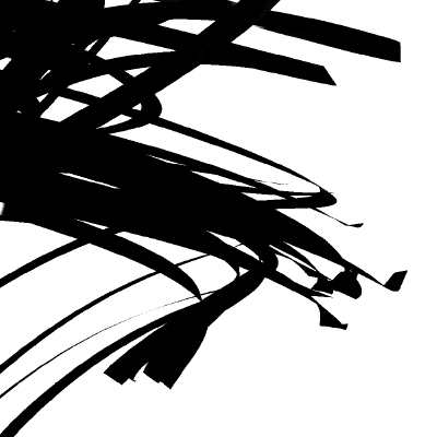
GitHub
Frame visualization utility for Unity. Contribute to keijiro/KinoVision development by creating an account on GitHub.
haven't tested out the repo personally
thanks
I'm trying to combine two meshes with different materials
I've given different parts different materials so they're seperated
but I can't figure out how to replace the placeholder materials
is this shader related?
well material related at least
There's a materials array on the mesh renderer. I think they're drawn one at a time, over top of the mesh. BUT your shader can be smart enough to pick and choose what it draws when. Or you want to look at multiple models and multiple materials. But you seem to be trying to combine, not separate.
Generally, you want to set it up with one mesh and ONE material...even if you have to atlas the material stuffis or make a separate special shader with multiple properties and you could, say, stuff a value in the vertex attributes to tell the diff between one polygon and another.
My best understanding. 😃
turns out that multiple materials + transparency absolutely destroys framerates
i thought that the performance hit of multiple materials was the same as just multiple objects with different materials
but apparently not
Yeah, you're basically passing it all twice. Then there's transparency and overdraw issues if you're doing that. Read->blend->write is expensive too. And overdraw is expensive with transparency because you don't get early-z culling.
Hello people, got a quick question. How do I add an outline (preferably smooth/fading) to my character that is not one object? It's several objects rigged together (like Body, Hair, Clothes etc)
Just a simple outline based on depth?
it doesn't matter to the camera if it's 1 object or not
Yea just a way to show that this is where you should be looking
Just a single gameobject too, not on every character
ah right yup that will work
what you working with? shader graph or default renderer?
SG on LWRP
Let me give a look, thanks @devout quarry !
although in the tutorial I do create an outline too based on normals because I want an outline around the little details in the object too, if you just want an outline around the object, depth alone is good enough
in that case you don't have to customize LWRP to generate a Normals Texture
also, outline based on depth/normals is just 1 method to do outlines but I think it'll work nicely in your case
this is the outline based on depth
So if my object collides with something it would outline the new thing as well, right?
only if the object has a material based on a shader where edge detection is generated
if you want all of your objects to have an outline, you need to work with an image effect
Ok, in my case this would be unwanted 😃
Let me read the thing
I'll come back with questions xD
yeah do let me know
It all seems a bit complex. Esp because I'm not too good with SRP code 😃 I'll have to try and implement it and get back to you later
Thanks for the help!
You don't need to customize the SRP!
that's only if you want outline based on normals
I think outline based on depth is enough for the effect you want

Pastebin
I believe this would be enough
just put this hlsl in a custom function node
and hook it up like this
in the code above I removed everything that has to do with normals so you don't need add slots for those
Let's give this a try 😃
Welp. I was struggling to understand why I was missing features from my package. Turns out I am on Unity 2018
And I can't change mid-project.
I'm sad 😦 I was so eager to use this as it seemed like the perfect solution
is there no custom function node?
custom function node is only available in 2019
too bad
I've actually used a custom function node. You just make it like a regular script
there's a hacky API available in 2018 but if you ever plan to upgrade the project it would break
It doesn't have the forward renderer asset step
CodeFunction is the script based one, Custom Function is built in to the node library
Well, I guess I'll add a halo to my girl LOL
I can't think of anything else for LWRP at least
if you do decide to upgrade, this is the effect I'm currently getting
depth only
This is exactly what I needed 😒 But I honestly can't upgrade at the end of the project
Yeah makes sense
does this outline color inside the silhouette of the target object?
you should need some kind of post process or rendering a silhouette to a separate buffer to add an outline outside the silhouette, i think
is this a question for me?
yas
I'm not sure if I understand but based on normals you can add an outline for the inside edges of the cube
like here with the cube on the top right
yeeeah that makes sense and is awesome
i was more thinking like
does the outline on the edge of the silhouette
only appear on pixels the object already would have been covering
this is a really cool outlines solution that sort of combines some of the advantages of the scaled/extruded-hull methods and the screenspace methods
yea i thought so, thank you
it's just checking the pixels around it for a depth and/or normals discontinuity
wanted to make sure i understood it right
if that discontinuity is big enough, the pixel gets turned into the green color
gonna add this to my collection of outline shaders ^ u ^ so useful
really happy that it helped
if you want to know more about outlines, I can recommend some blog posts from William Chyr
The work of artist William Chyr
as well as this tutorial https://roystan.net/articles/outline-shader.html
Learn to write an outline edge detection shader for Unity engine, integrated with the post-processing stack. This effect is especially popular as a compliment to toon shading, or in CAD and architectural rendering.
I can also help answer questions about outlines/edge detection 😃
oh yeah i've read all of william chry's stuff!
i thought i had implemented every type of realtime edge detection/outline shader but i guess it never occurred to me to sample the depthnormals texture locally xD
Anyone know of any unity fur shell shaders
i've made my own solution which i'm pretty happy with but don't know what there is to compare it to
Just found a really weird usability bug. ShaderGraph Properties you create don't have _ prepended to their Reference. As soon as you rename them to anything (even the same name) the _ gets prepended.
This means that you have no way of creating a new shader and naming a reference the same as the default on another material (e.g. for syncing two materials). Only chance is to change the reference of the original shader at least once.
dang
really
i think i encountered that
but isnt the reference somethign like Vector1AD7B88E at the start
so you would change it anyway
Well, if you didn't think you'd need it you might not - that's what I just had. Suddenly found I need to sync a second material with it (outline material with some vertex displacement).
Usually I would of course rename them to proper things, but since there's no "FormerlySerializedAs" or similar for ShaderGraph I would have to copy/paste like 300 shader properties over 20 materials when I do that
this feels so wrong
ah i see
wait what the
oh wow
that's fun
also my HDRP built project is stuck at the unity logo background colour
is there a known issue relating to this
want to do some more accurate performance tests
Is multi pass support coming to shadergraph/SRP?
doesn't look like it - but you can have multiple materials on the same Renderer to do similar stuff (not all of it of course, just basic things - outline in my case)
too bad
Any way to stop Unity from recompiling preview shaders whenever I update any asset
does anyone know what would cause this? it seems to be ignoring the fog completely.
The buildings are loaded in dynamically as assetbundles (using addressables)
The materials are using the Standard shader
It also only happens in builds, editor is fine.
that is really very odd
ooh this was autosuggested
seems like other people have the same issue
also i'm having a weird confusion
I would have thought that a value of (0,1,0) for the normal would be the same as not plugging anything in
i.e. this
would be the same as having no input
but it somehow isn't
WHAT
Z IS UP
WHY
WHY
THAT'S ONLY FOR BLENDER
AISHJDPIJAPGADGJPAIJp
ok calm
thanks @civic finch help me a lot
ah nice
😫
also does anyone know whether going from vector1 to vector3 fills in the other two with the same value or leaves them blank
like will this do a scalar multiplication of the out (3) or multiply the first element by the property and remove the others
Ok this is another one of those questions which requires experience with this kind of thing
with a hair/fur shader
i need to find normals without actual fur geometry
I have the tangent space normal of the fur accessible
and i need to find the normal off each hair strand
and i have no clue where to start
it's very hard to visualise, particularly given the multiple dimensions
and when i google it it's all about either already having geometry or doing it all from scratch
Vector1 to Vector3 will fill all three elements with the Vector1 value
Anyone knows how to achieve distortion on a transparent object using hdrp and shader graph ? I tried the unlit master node built in distortion input but it also applies to transparent object in front of my distortion. I also tried the "color scene" node way but it ignores all transparent objects behind it. Is it even possible right now with HDRP to have a correct distortion effect (on all the object (transparent and opaque) behind only) ?
Hi there,
Generate random number between 0 to 1 in shader unity, anyone know how to do that.
Unity Forum
Hi,
Is there any way of constructing a high quality random number generator in a surface shader? I've implemented one but I feel it is not very...
@keen mango Thanks Worked..
Hello
i want to enable shaders when level end
i make shine effect on image
when level ends i want to shader start shade image
how can i do that ?
What do you mean ? Like, at the level end, you want the full screen to "shine" ? Blur ? Fade to white ? ...
yes
Hi there,
I got a rendering problem but only on a very specific case : legacy forward rendering and Post process stack v2 with AO in Scalable Ambient Obscurance mode. Legacy deferred is working and the other AO mode is working too ...
Here is a screenshot of my custom shader :
@fathom anvil
You likely don't have the LWRP or HDRP installed (or don't have the Render Pipeline Asset installed in the Graphics Settings).
The question is about https://cdn.discordapp.com/attachments/497874004401586176/598459945247309834/2def8fd882f772ca74f3b0ebd3ba11a8.png being pink
