#archived-shaders
1 messages · Page 113 of 1
most see the fact you can hide part of the model as a form of transparency
but I get what you're saying
ok well thats not true is my point 😛
right
you can discard pixels on anything, its not transparency
it's opaque with cutaway
in SRP we removed this distinction
alpha test is available on everything and the alpha test "queue" is gone
that's why alpha test doesn't have transparency sorting issues
Awesome, thanks guys. That helped explained my issue for sure.
can't wait for your constants refactoring demo 😛
Slowly getting better 😢
just had to hard boot for the first time since I got this PC 4 years ago due to HDRP not using the gpu to create a rather large cubemap. Someone please tell me how I have the stamina to convert back to unity standard, and how HDRP really doesn't have much mroe to offer
otherwise I'm going to frustrated and throw in towel for another good while
@still orbit wondered if it's worth me rolling my own grass shader that uses signed distance field for the edge smoothness (AA) + alpha test only.
wondering since HDRP does a depth prepass so I might not gain any perf from this ... any thoughts welcome
hi guys, is there a way to use atomic adds for floats in compute shaders?
@broken field Depends on your setup I guess. Wouldnt you be doing this directly in the depth prepass anyway?
didn't think about it like that actually!
isnt alpha clipping always applied i nthe depth prepass in HDRP?
I read horizon zero dawn's techique of using SDF on vegetation (baked into the alpha channel) so figured it would be a nice pair for alphatest only shaders
@tribal plume the only info I could find about that is in this thread: https://www.gamedev.net/forums/topic/678937-atomic-add-for-float-type/
GameDev.net
Hi, I was searching the specifications for a possibility to do atomic addition for buffer variables of type float. But unfortunately I have found only atomic operations on integer types: https://www.opengl.org/wiki/Atomic_Variable_Operations This is a big problem for me now. ...
which mostly seems to say 'maybe on some hardware' and 'generally don't do that'
ugh, yeah it seems like i have to convert to int @frigid zinc then convert back
seems so
gonna have to cap it too to avoid overflow
Hello! Can someone point me directions/ materials how to learn the new shader graph, map types or shaders in general? I just finished watching Brackey's vertex displacement grass tutorial and started wondering how do you know/ learn which nodes to apply and when. Not much point of just adding nodes step by step while following a tutorial if you don't know what you are really doing
well I assume you know about the shadergraph documentation
other than that, it's probably a good idea to learn shader basics, even though most of the tutorials are pre-graph.
the concepts behind what you're doing remains the same so it's a good place to start
A collection of tutorials that cover how to write your own shaders in Unity.
as always I recommend this series, it starts assuming you know absolute zero about shaders and walks you up to some advanced concepts
he has also recently started a series on Scriptable render Pipeline:

A collection of tutorials that cover the scriptable render pipeline of Unity.
it's more broad but also has a section on 'custom shaders'
yeah probably true
That's the sg docs
mainly I suggest the first part, to learn the reasons for doing what you do when making shaders.
alright, I'll check these out, thanks!
I find looking at tutorials for other (shader) node graph systems will help your knowledge. All though SG is not as fully featured yet the all the knowledge is transferable. Shader Forge should have some fun shader examples out there, ASE, even Unreal's should help @short thunder
best way to combine meshes using different materials (20,000 + vertices, 10 distanct materials(shaders)/submeshes? (without creating a gameobject, so ECS preferably
that's what tools like mesh baker do
they combine the meshes and atlas the textures
so it's one mesh with one texture
combining meshes is easy
littler trickier to atlas but not that hard really
ah, cool,, so it's just liike a really long shader definition?
basically like, if you combined 4 meshes, it would adjust the UV space so each mesh's UVs take up 1/4 the UV space
and then combine the textures in that 4 quadrant arrangement
of course all the materials have to use the same shader
(i.e. standard shader)
ok, and yea, I'm been able to make some shaders really versatile , so that shou;dn't bve a big deal for my application
yeah you could probably do that if you're comfortable with shaders
Im getting there, had my first look in one when I needed to rotate my skybox, I've been perusing prefab files, obj file, and so forth experimenting with little changes ever since. There really self descriptive and easy to follow, but I do like just messing around with the node based approach better. Thanks @frigid zinc , going to give it a try and learn something new
Shader gods I have a question
if I have two sprites placed on the same spot. How can I show the half of each Sprite instead of the one on top?
I was told this can only be done with shaders
Shader gods, I beg your assistance.
I have a shader that scales an object, but after some prodding I came to realize that it doesn't work in my case because I'm using a flat mesh (A plane, pretty much), which means that its normals are always facing forward, so it can't be scaled along its normals.
Just multiplying vertex positions doesn't work either since it seems that the vertex position I get as input is the position relative to the world and not local space.
Any suggestions?
Scale relative to the center of the mesh?
float4 objectOrigin = mul(_Object2World, float4(0.0,0.0,0.0,1.0));
@plucky bone And then I just need to multiply objectOrigin by the scale value and pass it into output.pos = UnityObjectToClipPos(objectOrigin * _Scale); ?
Nah, you calculate the direction to your vertex from the origin
Then you do origin + direction * scale
Works great now, thanks 😃
Sweet 😄
So the method worked, but the result isn't really what I looked for.
The purpose was to get an outline on a mesh, but scaling the mesh makes it so that some edges of the shape have thicker outlines than others.
I know that the general approach to outline shaders is to extrude the normals of a mesh, but in the case of a mesh, all normals face the same direction, so that approach doesn't apply.
Any suggestions?

Game Development Stack Exchange
All these toon shaders I have been seeing render an duplicated mesh behind it and extrude the normals of the vectors to make it look like it has a border, but it feels a bit hacky to me.
Basically...
Thanks, but that only works for simple planes such as quads. In my case above each of the shapes is a mesh of its own.
any idea how to fix this? I want to combine them togheter, not show one over the other.
both of them are transparent shaders, yet the river shows above the lake
how to combine them?
This seems to be a sorting issue. Check the renderqueue
You could use a Stencil buffer to tell if a pixel had already been painted by the lake and not draw pixels from the river.
@tranquil zephyr I wont the effects to combine, not show 1 over the other. I want both visible. and @amber saffron they're on the same render queue
Combined in what manner?
right now the river shader is overwriting anyhting the lake shader is doing
I want to let the lake shader do it's thing, and then on top of that I want to apply the river shader
so I don't want to stencil anything out
Change the lake render queue to be lower, so it should be rendered before
the thing is, when inside the lake ( which is possible, I want to see the river still, so that won't work either
cause then it'll cause the same issue but the other way
also, it doesn't always "glitch" out
yeah transparency doesn't have depth but kinda does in HDRP
whenever I have a certain distance/angle on it, then it bugs out
other times it's perfectly the way I want it to
I suggest you make the river opaque and fake the transparency for it
or
disguise the meet between the two transparent obejcts because transparent does not write to depth buffer, one transparent object can only be in front or behind the other... does that make sense?
that's what is happening here its sorting
they don't meet, ever, they're just planes who don't touch
and can I not control the sorting? I thought that's what the render queue is for >.<
well the origin of the water plane is closer than the river and they're sorted like that
but it works 95% of the time, except it doesn't at some weird distances/angles
Also, it seems that the river is writing depth. I think it shouldn't
apprarently its not touching
yeah well the middles of each 3d transparent object is used to sort them
laughs at "middles"
More the center of the bounds irrc
the bounds of the object or the bounds of the triangle? :p
Object
But the RenderQueue sorting should get rid of this issue
Else, it could be a good idea to separate a bit more your objects.
Lake / River / Cascade
cascade?
don't know that word, (sorry not english)
anyway, messed with some more of the render queue and it worked, thanks!
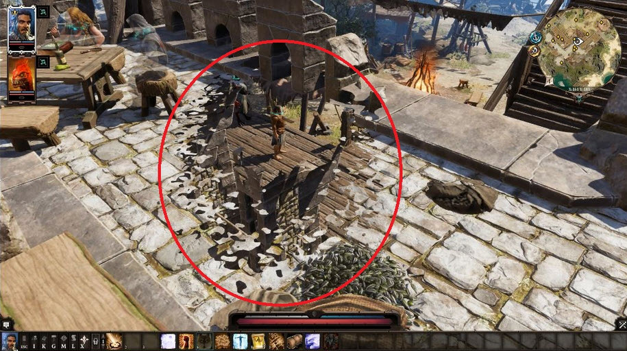
Hello, I'm trying to make this work but it doesn't quite seem to. https://gamedev.stackexchange.com/questions/152824/how-can-i-create-a-see-behind-walls-effect Can anyone help out? Thanks.
Game Development Stack Exchange
Divinity: Original Sin 2 has a beautiful see-through system. When I go behind walls, a splash mask will appear, and when I move around the game, it changes. It's like a dissolve shader, and has a
honestly that is a long and messy page
can you just take a photo of your version or upload it someplace so we can access it?
would be easier to see the issue from that
also which are you targeting, HDRP or LWRP?
I'm on standard. Does it have to be HDRP or LWRP?
I reckon since it's from 2015, probably standard.
So the guide said to "Use this as mask and this as the wall" https://hatebin.com/rbrnrqqphk < Wall https://hatebin.com/qtmiwrszbr < Mask
oh ok, I just assumed since I saw Shadergraph in the photos
Wait the post is from 1 year ago
How did I see 2015
Anyway I reckon the Wall one goes on the wall and the mask goes on the player?
i'll stil have to read the post to see how to use these so bear with me
No problem man. I appreciate the help.
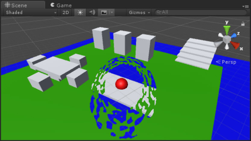
seems to be working for me
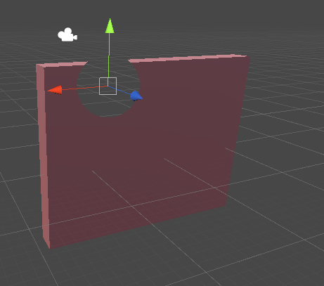
I put the wall on the wall
and the mask on the sphere
and the sphere is cutting out a hole when in front of the wall
or really when behind it
or really wherever it is
But the mask is always invisible right?
you'd put whatever you want to reveal behind the wall
Picture
and this sphere would reveal it
How the heck did he reach this https://user-images.githubusercontent.com/16706911/34574395-851a7682-f18c-11e7-8765-26ec2f5fee9b.jpg

That's what I was hoping to achieve. However I've gotten the same as you.
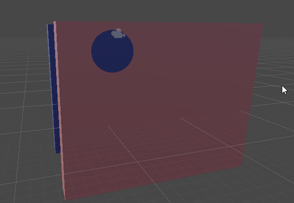
so like the blue is shown by the mask
now the texture yes, may allow you to perturb the shape of the hole
but you need a texture made for that
A noise texture or whatever it's called.
let me see what channel is used
yeah they are just using the texture as a mask
white and black
So getting this effect https://user-images.githubusercontent.com/16706911/34571588-2aca263a-f184-11e7-80c1-1a6c6f197f41.jpg Is not quite working.

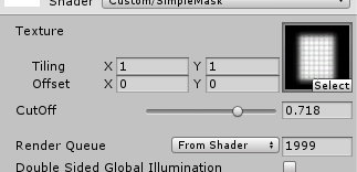
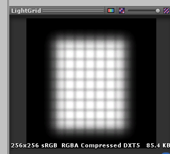
so see by using this grid texture for instance, and seting the cutoff

grid is put on the sphere and only reveals part
(would be better with a plane, not a sphere lol
but that's the general idea
you have to make a texture to create the look you want
Aaaah I see.
So you need a texture in the shape of what you want the hole to look like

yes, now the hole resembles the texture
the cutoff value decides how much is cut away and how much is not
Yes indeed. I see now.
I do understand now. So it seems I DID make it work, it's just that well I thought it would work on my player, so I applied the mask to the player and well the player disappeared 😛
Yep
The hole will look based on what texture you use
And you can animate it
To make it change size
you could even get really clever and make a sprite atlas that has looped animated frames
and cycle through them to make the shape wobble around and look cool
you'd have to modify the shader to support a frames atlas though. but i'm sure there's tutorials for that.
Unity Coding - Unity3D
Converted this old animated sprite sheet script into shader, its useful for animating sprites from sprite sheet. (when Animator is too heavy for simple sprite animation) Could be extended to have b…
something like that
Thanks man 😄
And can all this be applied on the player? So that when the player is behind a wall it does that.
you'd have to find a way to make the mask plane follow the player and stay oriented toward the camera
simple billboarding could handle the keeping oriented to the camera
there's a few ways to handle the following
maybe attach it to the player
or use some type of follow script
doesn't seem to work
Hm, the guy posted that as Billboarding.
well there's some billboarding shaders that are poorly done
Could be it.
i'd probably use the script variant if i'm going to move it anyway
using System.Collections;
using System.Collections.Generic;
using UnityEngine;

public class CameraFacingBillboard : MonoBehaviour
{
    public Camera m_Camera;

    void Update()
    {
        transform.LookAt(transform.position + m_Camera.transform.rotation * Vector3.forward,
            m_Camera.transform.rotation * Vector3.up);
    }
}
can use this with a Quad instead of a plane
have to manually assign the camera to the script variable inspector
So add the script to the camera?
yes
Sweet.
You helped a lot, I was quite confused at the start 😄
Now I know how what works at least.
Yeah I figured. Since it's the one that's suppose to move
Is it possible to use two cameras? One for actual player and stuff, the other just for this
I mean you could sure
you could put it in a layer
and have the other camera only render that layer I suppose
but it would have to be everything Plus that layer
otherwise there would be nothing for it to see through
but it's only going to face one camera, the one it's configured to
so in the other camera view it would appear facing the wrong way
but if that camera can't see it, wouldn't matter I guess
i wouldn't do it that way unless there's a very good reason though
makes it very complicated
It's a reasonably bad idea to do multi-cam-anything perf wise
Yeah true enough
well, not necessarily
Just complicates things too
if both cameras are rendering completely different things, it's fine
but if you're rendering the same things more than once, it's bad
for instance I use one camera to only render UI
Yea I suppose if the 2nd camera only rendered walls
and another camera to only render the rest
and there's nothing wrong with that at all
well unity will perform full culling per camera all over again, plus all callbacks etc for any stages it does. For a simple demo you won't notice any perf hit. but the perf hit rises quickly the more things there are to cull
there's no reason to cull for UI
and it won't show in profiler well
it will still do it.
it will still go through every single layer
not if you uncheck the culling box LOL
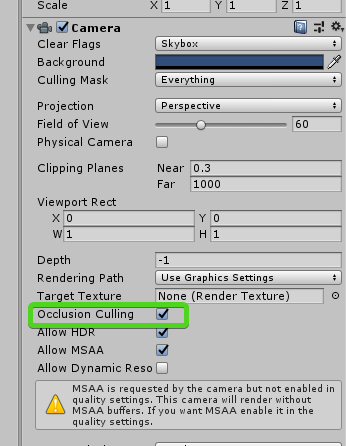
it will still do frustum culling per camera for everything, regardless if occlusion is ticked or not.
this is why unity disallow it on SRP
its well documented and known
doesnt matter
yes it does 😃
if you have no work to do, you can't say 'all that work will bog down your PC'
it's badly made.
it literally goes 'nope' and returns
they fixed it for SRP
it cant' check 'everything' the only thing in the layer is the UI
every camera in the scene will still check every layer, disabled or otherwise.
for every object.
unless you'd have me believe layers mean nothing which I call bullshit
it simply won't render it but it will still check it
hopefully unity will talk about it, give them a poke
you seem to have a strange obsession with optimization when you have nothing to optimize yet 😛
Optimizing is the last step in gamedev
best is using drawmeshindirect
then it wont have the culling overhead (by culling i mean it checks each object against the camera planes, it has to because in builtin renderer, the state of everything could have changed)
and (for reasons I don't understand) it will still do this even for stuff it doesn't render layers for
i dunno why it goes through all the layers
sorry don't buy that
if a camera is set to only render a layer
there is no reason for it to be worrying about anything that isn't in that layer
for all intents and purposes the other layers don't exist
well I read that from unity staff on forums and it was indeed years ago. i dont believe it changed though because I recall SRP discussion about why SRP disallows multiple cam rendering and this was one of the issues
it was also an issue for a couple of mobile titles I did - I found even excluding rendering layers didn't improve cpu time
but this is an older unity
will try find
maybe staff can correct me
(I want to be wrong in this case)
It is illogical for a camera to perform frustum culling on layers it isn't supposed to be rendering I agree
perhaps I mixed that up with their checks for onbecamevisible/invisible etc
well I've been using my 3 camera setup because ti was recommended (and true I forget who or where it was)
but I believe the object visibility might be one reason why cameras go through the whole thing
but it went against my better nature at the time, but I saw the wisdom of their argument after trying it
i haven't seen any performance issues from using it
UI camera, Scene camera, and both culminate into a main camera
which has all the Post effects
@sage hornet please rescue us!
the main camera doesn't actually render anything but post effects
the TLDR is that builtin renderer will still go through all the layers and check all objects to render per cam
or it may be the other way around
i have to go see, ti's been years since i looked at the camera setup
Do someone know how to port old shaders from Unity 5.1 GLSL into nowadays actual shaders?
GLSL to HLSL is a minor fix up
yeah I've never had much issue using unity 5 shaders in newer unity
only some minor issues with Fixed stuff
hmm, i have some kind of shaders issues after it's decompilation -_-
it's works only for 5.1

the Texgen stuff was depreciated
but they explain here how to work around the most common ones
SubProgram "gles3 " {
Keywords { "DIRECTIONAL" "SHADOWS_OFF" "LIGHTMAP_OFF" "DIRLIGHTMAP_OFF" }
"!!GLES3#version 300 es```dunno how to simple convert that shaders into new ones -_-''
oh you mean literal GLSL
just look at them
i didn't even know Unity allowed that, first time I've ever seen it
yeah i wouldn't even know where to begin
and really this looks like a ripped out shader?
so many 'tmp' variables
why not use shadergraph an make new if inexperienced
they are.
so you ripped these out of a game?
original ones gone with HDD, i did ripped them from compiled project before. And trying to update that thing from 5.1 Unity to newer....
Originally that is Android GLES shaders, wich is deprecated
well part of the rules here is: "you can't Share content or discuss any form of pirated or illegal content."
so unless you're saying this is your game, we can't even discuss this.
😉 there is question not about content enviroment
that question about how to convert such shaders.
I can and will discuss my peg leg, you can't tell me not to. I prefer a good oak polish finish and a fatter peg if I'll be doing general deck swabbing around the ship since it won't get stuck in holes or gaps and will also provide much needed stability when I lean.
but off-ship (usually when plundering) I prefer a slightly longer and thinner stump. As for pirate parrot choices, anything that nibbles me lobes and shrieks whenever I try to stealth is ideal.
hmm maybe is there some kind of tool for it... 🤔
well, i don't know of any way to turn a decompiled shader into original source code.
and even if I did, (i don't), i couldn't discuss it with you hehe
you've made ceebee grit his wooden teeth
^_^ no one like reverse engineers seems like that
in any event, because of the rules, i would suggest you abandon this line of questioning here.
is there the rule about decompiled shaders? If that is my own shaders? 0_o
Or i should you show off my Tencent contract?
print screen
Well, ok 😦
well it's odd if you own the game you dont' already have the source code
you could see why i'd be skeptical.
in any event, even if i wanted to help, i can't
what you're asking for really isn't possible
how do you declare the compute shader layout for unity compute shaders
is dispatch on the c# side the layout ? or is that the threads
bit confused which way around it is
as a programmer who is used to rolling his own shaders, how do I do instanced properties for ShaderGraph shaders, as I'd like to use MaterialPropertyBlock for some custom UI rendering?
Do LWRP shadergraph shader support it out of the box or is there something I have to do specifically?

Unity Forum
.ShaderGraph files are json files? Why not yaml?
Just a curiosity.
https://docs.unity3d.com/Manual/JSONSerialization.html
it's the built in text...
back in January they said they would be adding it 'soon'
so i have no idea if it's been added yet or not
I've heard instancing is a checkbox on the master node
but i don't know that means instanced properties
since instanced properties is a different thing from simple GPU instancing
i wouldn't be surprised if instanced properties isn't supported yet
it's pretty basic atm
cannot map expression to vs_5_0 instruction set
what does this mean ?
    v2f vert (appdata_base v) {
            v2f i;
            i.normal = v.normal;
            v.vertex =  tex2D(_HeightMap, v.texcoord.xy);
            i.vertClipPos = UnityObjectToClipPos(v.vertex);
    }
this is my code
it doesn't seem to appreciate tex2D =/ dont understand why
did you mean to assign to v.vertex instead of i.vertex?
i don't know either, why i asked lol
im wanting to displace vertices by my height map
my frag doesn't do anything yet i just want to see the mesh verts moving
unity's sample code adjusts the vertex on v
      void vert (inout appdata_full v) {
          v.vertex.xyz += v.normal * _Amount;
}```so i just followed suit
i think that's fine
but i notice the function doesn't return anything
you have a v2f return type
so you should be returning i
oh i just manually wrote it in here it returns i
this is someone else's very simple vertex displacement
VertexOutput vert (VertexInput v) {
    VertexOutput o = (VertexOutput)0;
        v.vertex.y += 10f;                       //here we edit the vertex
        o.pos = mul(UNITY_MATRIX_MVP, v.vertex);
        return o;
}
so yean not much different, just not using a texture
thing is:
            v2f i;
            i.normal = v.normal;
            //v.vertex =  tex2D(_HeightMap, v.texcoord.xy);
            i.vertClipPos = UnityObjectToClipPos(v.vertex);
this compiled
so its the tex2D its not happy with
cannot map expression to vs_5_0 instruction set when i try to use it
I've never heard of that error before
nor me
may need to change your #pragma target
what do you have it set to
try 3.0 or greater
The tex2D function is only allowed in the fragment shader. It cannot be used in the vertex shader or any other shader stage.
guess that's why
You must use tex2Dlod in the vertex shader. ```right so lod with x,y,0,0 im guessing
tex2Dlod(_SnowTrackTex, float4(vertex.texcoord.xy, 0.0, 0.0));
TIL hehe
That last zero is the mip level. If you change that to a 1.0 or 2.0 you'd use the first or second mip instead, assuming your texture has mip maps.
well at least it compiles now =/
hmm, disassembly of the shader seems to indcate it does create a CBUFFER, but I'm not sure if it's MaterialPropertyBlock compatible:
Constant Buffer "UnityPerMaterial" (32 bytes) on slot 0 {
  Vector4 Color_B907CECB at 0
  Vector2 Vector2_9610BD8D at 16
}
it would be nice if they automated that
but i guess the only way to really know is to test it
    v2f vert (appdata_base v) {

            v2f i;
            i.normal = v.normal;
            v.vertex.y +=  tex2Dlod(_HeightMap, float4(v.texcoord.xy,0,0)).r;
            i.vertClipPos = UnityObjectToClipPos(v.vertex);
            return i;
    }
Am i missing something here because this does not change the vertex positions at all
if i do v.vertex.y += someNum; it works fine
and i tested the image pixels in c# they do vary so it should be showing varying in vertices
it's going to be a value from 0.0 to 1.0
so at most it would be 1.0 which may simply be too small
try multiplying it by a value to scale the effect up
.r * 10.0
or something
(or better yet make it a slider so you can adjust it)
well the image isn't 0 to 1 is there no way to preserve the true numbers
the map has the literal height positions
i'm not sure what you mean 'there's no way to preserve true numbers'
any channel can have floating point values from 0.0 to 1.0
most textures are 8 bit per channel
which means 256 levels between 0.0 and 1.0
it's effectively 0 to 255
if expressed as integers
my texture isn't [0,1] on each channel they range with negative numbers
so i want to put the true value to my vertex y not [0,1] * scale
i'm not sure how a texture can have a negative number in it
ok i see
though even with * scale assuming its 0,1 its just moving everything up equally
then i don't know, other than maybe that sampler can't handle float textures
maybe there's another sampler function specific to that type
hm
i'd maybe make a debug
which is easier said than done
debugging shaders is very hard
but i'd try to downscale your values into the 0.0-1.0 range so you can plot them as colors on a surface
and see if you're even getting your values from that texture
because right now it sounds like you're not
if it's supposed to be getting values of that magnitude
I've never made a shader that used a float texture
so i have no experience with how that's done
hm maybe, but i will lose a lot of data doing that
yes i mean just for debug purposes
if it comes out a solid color
you know something is wrong with the sampling
well im not losing the data in the image so ive ruled that out at least
but if you get a pattern roughly analogous to what the input was, (but compressed), then you know the sampling is okay.
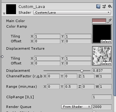
regular unlit shader
@frigid zinc you're welcome to try
use some ordinary height map on a nicely subdivided mesh
da fffffck
that was a plane before I put a texture on it
can you show me the height image you're using
maybe your mesh doesn't have read/write enabled
I think it has to be to use displacement
not sure tho
or maybe your mesh has no UVs?
pretty sure you'll need UVs to make it work (read/write doesn't seem to matter)
uvs, normals.. could be lots of things
ah it works now
which was it, Uvs?
not sure i just re-exported and it worked
heh well, good enough I guess
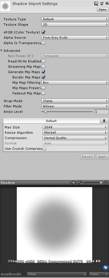
material set texture allows texture2d right ?
the thumbnail in the inspector just shows black even though when i saved it to file it is showing correctly
should
that's the floating point texture? may not thumbnail well, I don't know
i don't even know how to make a floating point texture lol
_displacement = new Texture2D(N, N, TextureFormat.RGBAFloat, false);
like that lol
well i meant as an asset
photoshop does have 32 bit per channel format
I've never used it though
i wonder if it's floating point
i think so, it's only giving me a few save options lol
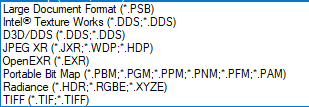
will try intel's DDS
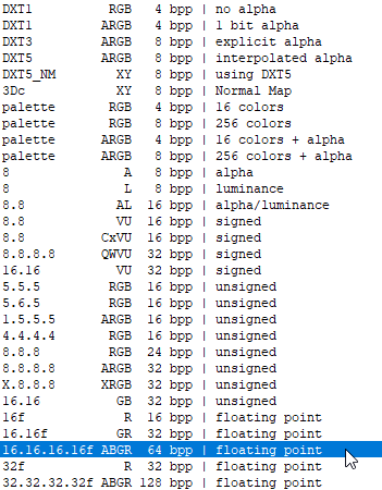
yeah that will do the trick
see what unity says about it lol
so its RGBA reversed?
im hellish confused lol
i presumed if i set it to rgbafloat it would preserve the data in the shader too
yeah see unity is not even making a thumbnail
but still says RGBA
they must swizzle it for uniformity
i dunno tho
shaders don't seem to understand that format at all
everything is just black
i tried the 32 bit per channel
let me try 16 bit per channel
unity doesn't support that one
yeh im getting just black too and my mesh is just disappearing to i assume all zero
though it shouldnt because im only adjusting the y value
i dunno i'm starting to wonder if unity supports floating point textures like this
Unity Forum
I am using a texture of type RGBAFloat, which I initialize with setPixels.
I expected floating point precision to be preserved as setPixels takes an...
doh
Is _MainTex's sampler declared as a sampler2D_float?
so there is a special sampler
but is there a sampler2d_float_LOD
or sampler2D_LOD_FLoat?
hmm this guy says
I used a RenderTexture of type RGBAFloat today, to get the full precision of the Depth Texture
maybe i need to use render texture not texture 2d =/
otherwise i have on idea whats going wrong
oh wait i'm getting sampler and tex2d mixed up
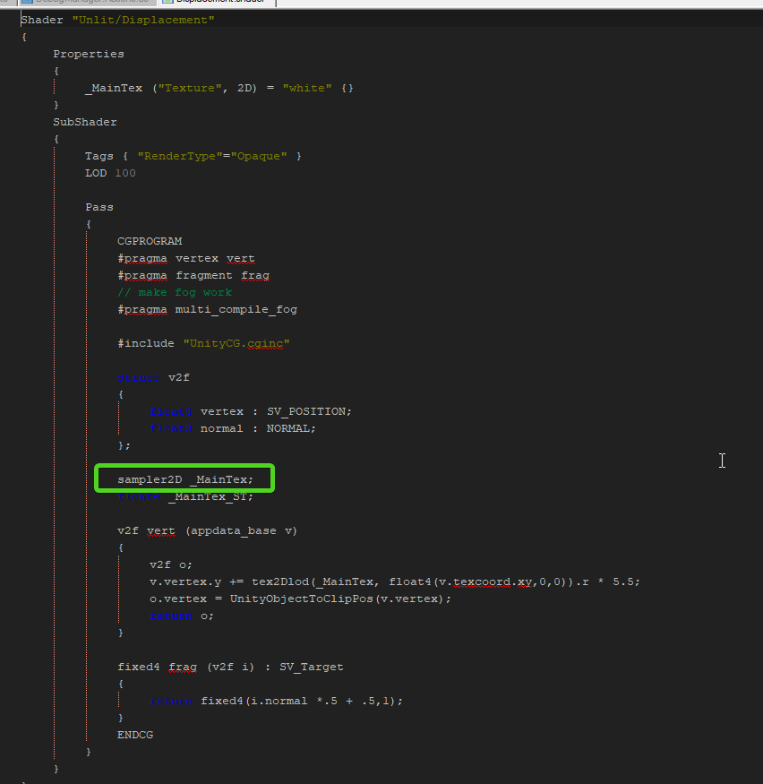
it's this, needs to be sampler2D_float
not sampler2D
then tex2dlod should be able to read it as a float
tried that
its a pain that i cant do it in pixel shader
maybe i should give it something else instead of a direct texture2d here:
_renderer.sharedMaterial.SetTexture("_MainTex", _t.displacement);
yeah i dunno, i'm totally winging it
lol 😛
i can really find very, very little about people using floating point textures in shaders
it's like it nearly doesn't exist
Unity is the ultimate game development platform. Use Unity to build high-quality 3D and 2D games, deploy them across mobile, desktop, VR/AR, consoles or the Web, and connect with loyal and enthusiastic players and customers.
this is really the only example of it I've found so far
and they seem to indicate it 'just works' but having problems on some phones
i don't see anything magical they did
well - no one cares about phones anyway
hm see when i manually put the file it shows the thumbnail
if i do it in code it shows black
it must be losing the data or something
I assume you are Applying the pixels?
I mean when you create the Texture2D
oh i use SetPixel()
and then Apply()?
seems to save the data to it
no ? didnt seem to need to as the data was present when i ran through each pixel
Use Apply
what does it do
it will show you the texture on the CPU
otherwise it's GPU only
as far as I understand
I'm not certain though, either way it should make the preview work
😮
why did that work even though when i ran through the data it showed the values correctly
at least it works now
@vocal narwhal
thanks
Actually, without calling Apply the pixels are not even pushed to the GPU
good to see it's working 😃
what about graphics copy texture
it says Alternatively, if you don't need to access the pixels on the CPU, you could use Graphics.CopyTexture for fast GPU-side texture data copies.
but im confused on the differences at this point
can only copy one texture to another
oh so graphics apply is a shader doing the copying ?
ohi thought you had a texture
i didn't realize you were generating it on the fly heh
ah lol
but I wouldn't know about 'apply' anyway
Texture2D.Apply uploads the changed pixels to the graphics card, I don't know the implementation, it's external
I've never generated a texture at runtime either
is there a way to directly set a texture to a shader from a compute shader?
as i plan to move all of this to compute shaders
I imagine so but I've not done it before 🤷
yeah i found a ton about that when searching
like you could blit with a material and write whatever you want with a shader (I'm thinking ComputeBuffer, ComputeShader is different, never mind)
was pretty much all people talked about in reference to floating point textures
even with 256 dimensions ive got lag on cpu lol
but I'm not sure if that's the best way
hm i see
yeh this stuff is a bit confusing
would be nice if unity made a more clear explanation of it really
is there a way to directly set a texture to a shader from a compute shader? @quaint grotto you can have a compute shader write into a RWTexture2D which other materials could use as a Texture2D and sample from, if that's what you're askin
but does that still require the cpu to push it across @uncut karma
not if the logic happens in compute, then its always GPU side
so how do you actually give that texture2d to the shader on the material from the compute?
if you have some parameters you'd like the compute shader to use from CPU side they could be in a constant buffer array or StructuredBuffer (compute buffer) of whatever custom struct needed
because my cpu doesn't need to know about any of this once i move it all to compute
you'd use a RenderTargetIdentifier most likely
well my time dependant algorithm just receives a time uniform but other than that not much else between them for cpu
so the texture would be render texture that gets set on the compute shader, and then also set via material property block for any renderers/materials that need it (or set globally)
ah yea, _Time and all the other standard unity variables would be accessible in compute
oh actually i need the resulting texture from compute for physics calculations on cpu
i see, depending on what information you need back, it could be a structured buffer
and then you'd use the compute buffer GetData and put it into an array or native array
but that still eliminates me having to push to my material from cpu
it's still awful slow getting data back from the GPU
which would be GPU to CPU but depending on size of array and bytes of each entry it can be quick
its slow but nlog(n) is slower on cpu 😛
if its too slow you could do something where it updates in parts too
whats the main bottleneck for transferring to cpu ? the data size or the frequency of it ?
or both
not sure technically, but i think its not as efficient as it could be & if i remember right it soundedl ike something Unity is aware of improving (possibly related to NativeArrays)
you may want to look into this https://docs.unity3d.com/ScriptReference/Rendering.AsyncGPUReadbackRequest.html (i havent tried it yet)
but it wouldnt stall, but just may have latency
i only need the send back to cpu as often as my physics tick rates
so at least thats a slight optimisation
i could probably get away with more since its water and not totally rigid
could probably store the last result on cpu side and lerp to the latest to keep it smooth too
I wonder if you could do a little GPU physics and return a tiny block of forces for an item sitting in it - it really depends what your needs are in that case though
seeing as it's buoyancy and not collisions it's a lot easy
it'd still only be viable for a few items I imagine
yeh, will see how i get on over the next week or two i still haven't added horizontal displacements anyway
Any suggestions on how I would go about rotating a direction vector (Want to rotate a normal)?
Use a rotation matrix
quaternions @tranquil zephyr
or rotation matrix if in shader
setting anti aliasing to 8 samples on a render texture doesn't seem to apply MSAA to it
I define the color and depth buffers for my camera with AA disabled, then blit it to a separate render texture with AA set to 8 samples, but the two depth textures look identical
funny, someone the other day was complaining they couldn't get rid of the AA on their depth texture
but they were using TAA
lol
I enabled allowMSAA on the camera, but if I set the samples in the color / depth texture to non-zero values, it just renders black
@fervent pelican @frigid zinc
old chat:
"you'd need a 'wavy hole' texture"
he would need a noise map and a radial gradient blended 😉
I can't find a cutout option in SG LWRP. Am I missing something?
😛
i like wavy hole better ;p
should be there, once you set a shader to use Transparency, the 'cutout' stuff is a checkbox in the settings below
SG needs more parametric 3D map nodes like dent and cellular in 3dsmax.
Cutout is not there in SG.
Nor is sorting options which are there in the standard shader.
hmm well i only tried in HDRP the other day
maybe LWRP doesn't have it, but that seems odd to me
let me look
It is available in LWRP, but not in SG. (4.10.0)
yeah these things are a bit silly. not helpful.
i.e. right now i want to try a cutout with blur to create a more fuzzy/soft cutout.
it would be up to the master node implementation to provide a "cutout" option like standard/built-in materials and that's on the render pipeline
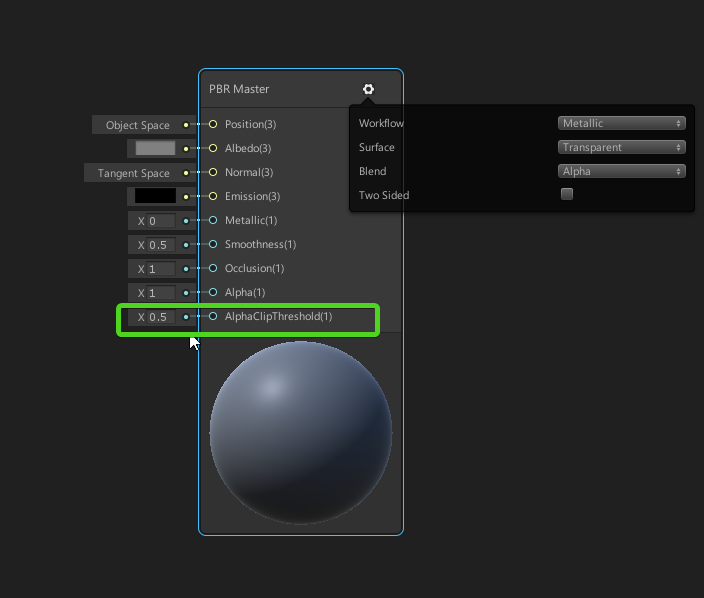
I am using the standard PBR master node for that.
that's on the render pipeline specific team to implement*
but ya just use alpha clip threshold
Alpha clip only works when you choose transparent.
are you just using the default binding?
and it only pushes the edge of the "alpha"
yeah well that seems to be the only option
default binding = the default int field widget shown in ceebee's image
I know. But it is not cutout. When I switch to Transparent it creates sorting problems.
there's a bug with the default alpha clip field. you have to plug a vector1 node into it or some other edge in order for the ALPHA_CLIP keyword to get defined
so if you do that, you should be able to do opaque and alpha clipping
wyatt I am not very familiar with this .
ok I will try that. Thanks
ok looks like this fixed it. thanks. now to the more difficult part. making this blurry 😄
I will try diffuse/dither (edit, nope dither gave me alpha sorting issues...)
@dry island I found some noise map.
real time raytracing guys?
is it a thing you can implement as of now?
I'm talking metal katana
i already answered you in General
any one familiar with atomic functions
if so can you ELI5 how they differ to normal functions
😢
you can think of them usually as operations that are instantaneously & finish in one step. So say you're writing a kernel that spawns multiply threads, and those threads act on shared memory. With non-atomic operations you might alter this shared memory in one thread, but since the threads run concurrently the other threads don't know about this change.
If you use an atomic operation you might for example change a value in shared memory & all other threads will know about that change while they're still running
right so they are useful if/when altering data that all threads rely upon ?
but what if you change the value and some threads have already processed that particular value in memory and now its changed? does it have to do it again
no, atomic operations are guaranteed to be executed before that happens
Arrays are not packed in HLSL by default. To avoid forcing the shader to take on ALU overhead for offset computations, every element in an array is stored in a four-component vector
so if i have [0]=1, [1] = 4.5f on C#
in compute, to get 4.5f i have to do [0].y ?
or have i misunderstood that
sorry if this question has already been answered, but is the new custom node (ShaderGraph) already here in the current 2019.1 / 2019.2 beta version ?
The changelog on github (https://github.com/Unity-Technologies/ScriptableRenderPipeline/blob/release/2019.1/com.unity.shadergraph/CHANGELOG.md) say it is, but it's in SG 5.8.0 and the latest I can get through the package manager is the 5.2.3 version.
Show preview packages?
same thing
Your version of unity is?
some packages are only visible to some versions due to compatibility.
The latest that I know of, I tried 2019.1b8 and 2019.2a9
I can only assume it's not updating package manager's list
or something not very helpful to you :P
( I am on 2019.1 beta 8 with 5.10 )
..and yes function node is available in 5.8 and above
is there a way to bypass it by playing in the manifest.json ?
I no longer meddle with the manifest
or do I? I can't remember
I will call the genie
@shadow krakennto wherefore art thou?
well lame
well thanks for trying to help 😃
well a few more info,
my 2019.1 install is stuck on LWRP 5.6.1 package and says it's up to date
my 2019.2 install is stuck on LWRP 5.2.3 package and says it's up to date
Both installs are fresh from tonight.
Both projects are empty, created from "LWRP" template
does pp stack have gaussian blur?
and in both project, I get this error when I open it
"Failed reading from: '50/50c60386aa2616bbcc444ba0bd47ec27.ghd'."
is it possible that the server that provides the latests unity packages is down ?
ok my bad I feel quite stupid right now;
I didn't see that you could expand the thing next to the package; I was only looking at the bottom right button that says "Up to date"
anyway it,s a bit weird, it says "up to date" even though I can expand then click and select 5.10.0
don't feel bad. I couldn't find that down there last night either 😦
i hate when they move UI stuff on you after you learn where it is lol
well i think the newer ones are still considered 'unapproved'
risky to use
the ui still sucks even for 2019 i mean come on even blender is getting a ui upgrade
its got that windows xp vibe
yay
ah okay so beta 2019 until 2024 then maybe its released 😛
yeah there it is, i couldn't find it
glad they ain't totally moving everything about just making it neater
i'm not a fan of how monochrome and flat it is
I dislike the the dark background colour also being used as the input field colour, makes them seem related when one should fade away and the other be super important
has anybody used the scene color node in shader graph for HDRP?
it just returns black for me
thanks @frigid zinc for your help earlier, I can now test the custom node in shadergraph
it's working once you get the UI stuff 😃
however I'm so sad they totally removed the C# way of doing custom nodes.
I mean, how is this supposed to replace everything I did with my C# nodes ? custom master nodes ? custom UI for my nodes ?
well, i think the general consensus is you shouldn't be doing custom UIs, and anything code-wise should probably be done in the shader code itself.
but it's early
stuff could morph once again before it's all said and done
I live for custom UI so that hurts
I hope they introduce an API just for that really
yeah i can get that, especially since editor UI is a thing in unity
yeah, an example is I got an integer in the UI but I want to apply a pow() before I pass it to my shader so I can remap it and it's much easier to use; am I supposed to put the pow() in the shader graph or code instead ? what a waste of performance !
well maybe if they see more examples like that it will motivate them to do something
but how would that work once the shader is out of shadergraph and in the material editor
does that type of thing still work? I was never able to try it myself
if it doesn't, that may have been their concern
well it can work, it just has to be serialized in the material after the pow()
worst case you can still do a custom shader (Edit: custom shader UI) and it'll work
and something that bothers me is, they use custom stuff in their own node so they know it's useful
look at that
they have custom UI all over the place, but we can't use it anymore
anyway I'll stop the rant :p
but like you said, I hope they'll see the light and walk in the custom-node-for-all path !
my fisrt shaders, didin't know to leave blank 2d texture nodes, and forogt to add gpu instancing nodes, but I think I'm getting addicted to shaders
congratz @mossy smelt ! Looks cool !
@sand perch thanks ph!
Hi,
I'm trying to set shader graph exposedProperty using Shader.SetGlobalVector in order to have the property set to all materials using the shader but it does not works. Is it possible to set a property value globally ?
a property you set globally shouldn't be exposed in editor i believe?
In this video the person does expose the property and it works for him.

Use Unity 2018.3 Shader Graph in the lightweight render pipeline to make a toon shader graph (cell shader graph). That is what I go over in this tutorial vid...
FYI I created a poll to see how many people were interested in the 2018.x node API and would like to have some similar features in 2019.x. I can't be the only one, so please vote !
https://forum.unity.com/threads/2019-1-shadergraph-custom-nodes-poll-please-vote.648454/
Unity Forum
(I hope this is the right place to set this kind of poll)
As many of you probably know, in 2019.1b, Unity has changed the ShaderGraph API and how...
hi, i'm wondering if anyone here might know a solution to this. In a handheld AR app, outdoors, i want the video feed to be in the foreground, and cutout sky pixels so i can render my own far distance landscape and sky graphics. Presently I'm rendering the ar camera to a texture, and use a separate camera to render that as a raw image onto the screen. Now (i think) i just need some kind of histogram controls to identify sky pixels and make them disappear. Suggestions?
@stone shard To identify the sky in a photo.. sounds like a tough job for machine learning. I don't think you can get nice results with cutting a color range. Best bet might be to ditch the idea of a cutout in the camera feed and go for a nice fade from the camera feed to your skybox with spacial tracking and an inverted sphere
yeah you'd have to do your filming in front of a greenscreen
so you could replace the green with your procedural sky
or be very careful to have a perfectly blue sky and nothing else in your scene use blue
there's high-end video editing software that can use landmark tracking to do the cutout
but of course that means you have to have that kind of software, and process the video offline before doing the compositing
Hey guys! I'm trying to convert some shaders that were used by particles with vertex streams using ShaderGraph, the thing here is that I'm not entirely sure how to approach the declaration of the attributes on the generated code.
Anyone knows how can I ensure that the streams match on my shader?
Thanks. @outer lintelebee i need to do this at runtime, outdoors we'd need a greenscreen a mile wide! 😃 @tidal fjord it doesnt need to be perfect just a range of pixel to ignore that are in the "sky range", we'll assume the land/horizon is significantly different colors than the sky (eg not worry about foggy or snowing landscapes). Further thoughts?
i figured the user can just point the camera at the sky, drag a rectangle to define the pixels, then some kind of shader that matches similar pixels and doesnt render them ?
ARGBFloat Color render texture format, 32 bit floating point per channel. does this mean the alpha channel is now under .x ?
yeah I think the page makes it clear
not really lol regarding which channel is alpha
unless i take the name to be telling me so
that's how it's stored in memory
but I don't know that's necessarily how you access it
i was under the impression unity normalized all textures to RGBA
if you're working in a shader
best to just use rgba instead of xyzw
then there's no room for confusion
don't know, don't care. you just know you'll get .a 😃
no matter how it's stored
i would like to see a definitive answer though
i have a feeling it's one of those things you'd have to test yourself
yeah i guess, just found it odd it was named ARGB to start with
like i guess its important but i dont know why
because that's how it's stored in memory
and it was video card mfg who defined all these formats
we're just living in their world 😛
fuck those guys and their confusing designs 😄
might be less complicated if i just use a 2d float array over textures perhaps
but i dont know which is more performant on a compute shader
i presume texture look ups are slower than array access?
i dunno
is there no "get" texture method from compute shaders =/
getting this error: undeclared identifier 'Process' at kernel Process
https://hatebin.com/avkljgwqzc
Any idea why?
nevermind
solved it
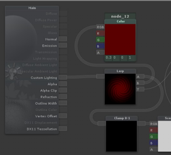
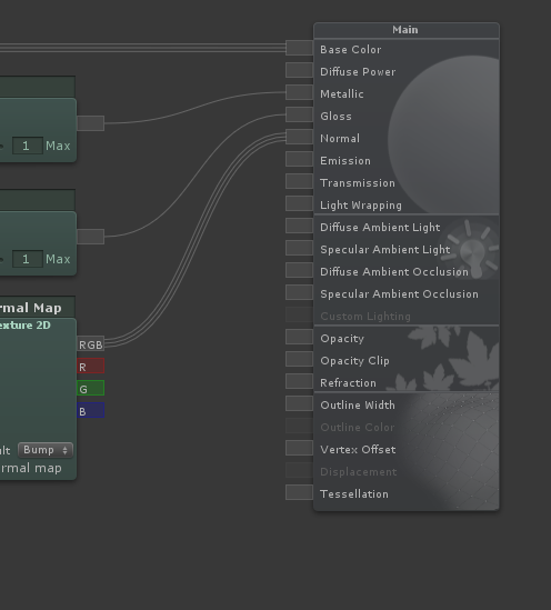
ok this is a dumb shaderforge question, so I don't know if anyone will know
but I keep seeing node images like this:
but my shaderforge window is like this
so how are they flipping everything horizontally so it goes right to left?
old shader forge versions were right to left
then she changed it to left to right
@frigid zinc
no idea if they left in the option to switch it back though
oh ok
yeah I looked through settings, didn't see anything. I was just wondering why some were that way 😃
I made a pretty simple shader for sampling and combining textures using Texture2DArray and it seems to work just fine until i enter/exit play mode or save the unity proj. Then the textures disappear until i rebuild the texture array and set it to the material again. I have both the textures and the array set to dontdestroyonload. None of them go null. Is this due to Graphics. CopyTexture just operating on the GPU or something?
if you are setting the textures via a custom editor/scriptable object, you may need to set the editor as dirty, or the variables as serializable
I'm not, just directly through a script they are marked as serializeable. It's just testing. But it does seem odd. The quad just becomes grey on play. If I build the array and assign it to the shader/material after that, it continues to show until I exit play or save again. Again, nothing becomes null. I thought I'd read that graphics.copytexture was a GPU operation or it copies to GPU and not cpu, which i assume is my issue, but idk how to fix that. I guess I could just simply rebuild it everytime the scene changes or on play/exit.
😮 yay it worked !
https://docs.unity3d.com/ScriptReference/Graphics.CopyTexture.html
Last paragraph there states that CopyTexture operates on GPU side data exclusively.
If my texture array has to be build at runtime i guess i can't keep that around between loads or saves, and just rebuild it as needed.
did you use .apply () afterwards?
@mental helm
thought not sure what your end goal is
I'm feeding the shader a texture2Darray of parts of a 2D character and "flattening" them on a quad. So i get diff clothes and customization with a single renderer and only loading the textures necessary.
That doc i linked says calling apply causes unpredictable results because it's not meant to be used together i think. Pretty sure apply is to be used with get and set pixel while copy texture is used with GPU side stuff only.
Like i said it all works and everything it just seems that the texture array created without saving it as an asset loses its textures on the GPU when loading. The references to textures and the array themselves stay within my script just fine and serialize and everything.
@quaint grotto
https://forum.unity.com/threads/how-to-make-texture2d-array-survive-into-next-scene.27067/
This post seems to reference the same thing but they solved it by making each texture dontdestroyonload. I've done then exact same thing but it still doesn't preserve the textures they just become grey
Unity Forum
Hi.
I'm struggling with the image in my Texture2D array getting blank whenever I load a new scene. There is data in the array because the width,...
you say when loading ? do you mean when you change a game scene
i think but i might be wrong, declare in your shader your 2d array as uniform
I haven't tested with switching scenes when the game is running. I just simply built the array in the editor through script. If I save the scene or enter play mode it goes grey. If I build it again when playing, it works until i exit play mode.
sec let me check if thats the right keyward
Hmm. Tbh i made the shader in ShaderGraph. Can I do that through shadergraph? I guess i could just rewrite the shader myself
Yeah worst case that's what I'll do. No big deal.
i think that would be better than using dont destroy on load
dont destroy on load is best for something like a singleton like a game manager
Yeah. I was really just trying to get it to work atm. It's weird though that the array doesn't become invalid. It still reports the correct number of textures and the sizes of textures and everything.
No errors or anything.
hm not sure
Thanks for the help! :)
didn't really help but np 😄
Anyone knows how to convert the sv_position in a frag function (I assume it's clip space?) to either world or, preferably, screen space (Either normalized or pixel position based is fine)?
Actually, I seem to be able to get the result I want just using sv_position itself. What I was aiming for was to set a property in the shader based on the x position of an UI object, and render everything on its left one color and everything on its right in a different color.
I have a weird question. I made a shader, partly putting it together from existing pieces and something I don't understand happened.
As far as I have seen, in general we make our vertex function return data we're interested in using. Then, our fragment function takes that data as an argument.
However, I was just cleaning up my code and I noticed that in one of my passes, the returning type of vertex function's doesn't match the fragment function's argument at all. And it works. Why does it work? What happens underneath?
Here's the code:
            #pragma vertex SimpleVert
            #pragma fragment Frag
My vertex function returns a float4:
            float4 SimpleVert(float4 v:POSITION) : POSITION{
                return UnityObjectToClipPos(v);
            }
... but my fragment function takes a v2f argument:
            float4 Frag (v2f i  ) : SV_Target
            {

                float2 uv = i.texcoord.xy;
                float4 color = _Color;

                return color;
            }
That v2f is a struct I used in my previous fragment function I no longer use. The struct goes like this:
            struct v2f
            {
                float4 vertex : SV_POSITION;
                float2 texcoord : TEXCOORD0;
                float4 screenUV : TEXCOORD1;
                float3 ray : TEXCOORD2;
                half3 orientation : TEXCOORD3;
            };
Again - why does it work? What exactly happens between vertex and fragment functions in the pipeline?
I'm not quite educated on this matter enough to give a confident answer, but my guess would be that it actually isn't giving the correct value.
If I'm correct, when the float4 is returned instead of an object, it's passed in memory as the first value on the offset at which the v2f object should start.
Since we're using C and objects aren't actually a thing, casting between types is simply a process of looking at the same offset in memory and looking ahead a certain amount of bytes.
So for example, if you had 4 bytes in memory starting at offset 0x0 with the following values:
0x0: 0001
0x1: 0001
0x2: 0000
0x3: 0000
And you were to look at a byte starting at offset 0, its value would be 0, but if you were to look at an int (Which uses 4 bytes) at the same address, you'd basically just look at the 4 bytes starting at that offset and treat them all as the same int.
That means that in the case above, your int would contain the binary value 00010001 (or the integer value 17), even though when looking at the same offset as a short would return 1.
In your case, that basically means that you're lucky it works since the first value in your v2f struct is a float4, and you're returning a float 4 from the vert function.
But the rest of the data in the v2f object would be garbage.
tl;dr, the returned value is not correct, you're basically returning only the first value in the v2f struct using the value you're returning.
And now for a question of my own!
Is anyone aware of a way to do shader replacement but instead of not rendering objects that don't match my tag, display them with their original shader?
@tranquil zephyr Ok, thanks for clarifying - I get it now. I just have one concern now. The variable in v2f I'm actually using in my fragment function is texcoord, which is not a float4, nor is the first variable in the struct.
So in theory it shouldn't get initialized properly.
Also, why does the SimpleVert have an argument? What gets passed there and how? I can see different vertex functions using different arguments, but I don't control what actually goes there. This data migration between functions is currently the most confusing part of shader programming for me.
I could imagine that those : SV_POSITION, : TEXCOORD, etc already fill those structs with proper data, but optionally passing arguments of specific types in the earlier functions in the pipeline lets me override some (or all) of the automatically initialized variables. Am I correct?
Also sorry for burying your question @tranquil zephyr . 😑
Oh, you're right, I didn't notice it was the second thing.
So maybe I'm wrong about the whole thing, but as I said, it's just a guess.
In your case, I think that might be related to the fact that the vert method is decorated with : POSITION at the end, which might be a cheat to telling it where to map on the created object?
But again there's a discrepancy - Vert is decorated with : POSITION, but the variable in use is decorated with : TEXCOORD0
About input values for vert, as far as I understand, there are some reserved words in the language that map certain values into the input object. POSITION in one of them.
So doing float4 v:POSITION as your parameter would be the same as doing
struct input
{
v : POSITION;
}
The Unity Manual seems to suggest that anyway, atleast for Surface shaders:
https://docs.unity3d.com/Manual/SL-SurfaceShaders.html
So I assume Vertex shaders would be the same way.
That's true. That's a part I still find confusing as well ¯_ツ_/¯
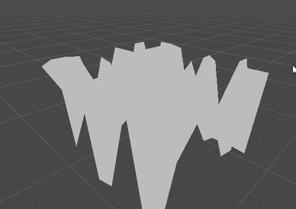
I tried making a simple wave shader in hdrp
but if you look closely I get these lines on the 'hill' of the wave
any guess why this is the case?
Looks like self-shadowing.
shadow bias options
you should generate a normal map for the surface as well each frame
doing so will improve the shadows
+also further improve shadows if used in forward+
(hdrp forward)
will try, ty!
Is anyone aware of a way to do shader replacement but instead of not rendering objects that don't match my tag, display them with their original shader?
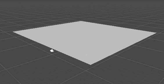
@broken field Speaking of generating a normal map, that's something I'm dealing with right now with my own water wave shader.
I'm displacing a tessellated quad based on a heightmap from a wave propagation simulation. I found a code snippet to generate normals from the heightmap, but I haven't figured out the right way to apply them in the vertex shader.
Here's what the generated normals look like:
How do I take that and apply it to the existing normal on each vertex?
hey there is actually a node for converting height to normals in shadergraph
but how I did my water was to use partial derivatives
ddx and friends - allows me to sample the pixel next to the current, and the difference between will obviously be the angle
So I actually recommend a separate normals generation pass to generate a normal map, if this can't be done then probably can just use partials in vertex
if generating normals, use a 256 normal map so it stays inside gpu cache
(or, this isnt' going to be a bottleneck anyway tbh)
how do you know a 256pixel map will stay in the cache
i'm not familiar with that idea
In shader forge there is like a depth blend node and in amplify it's called depth fade or something, is there something similar in shader graph?
probably not, right now Shadergraph seems to be sticking with the basics. And that kind of node is really a 'generated' thing, from available data and some math
it's basically doing some forumulas for you
you'd probably have to create a similar function yourself using the Scene Depth Node
okay ty
+1 with ceebee, it's 100% doable, I did a transparent light beam that fade out when it hits the camera or any geometry 😃
tbh I know nothing about shader coding but I'm looking at shader forge source code, and together with the Unity API to create custom nodes I should be able to figure this out 😃
do you guys know if there is a way to use mesh distance fields to do some water shoreline? I've seen this technique used in unreal here: https://80.lv/articles/cartoon-water-shader-in-ue4/

Adam Homoki did a breakdown of his beautiful Cartoon Water Shader made in UE4: waterfall, waves, caustic effect, interaction, color, and more.
I know we can make SDF in unity (like raymarching) but I doubt we could use them like this
in the end everything is math, and math can be used in any engine
there's no reason that technique won't work in unity if it worked in unreal
i seem to recall someone showing off their thing to turn meshes into SDFs awhile back
lol, it's like saying "a screen is only an array of value"
so i know at least one person has done it already
haha ok ^^
well it's true 😛
but does unity have a built in SDF system, no
let me search back and see when ppl were talking about that
that's the difference with unreal right
thanks !
it looks so much better than using depth test for shoreline
yeah mostly it centered around this article:
NVIDIA Developer
and this tutorial

This tutorial explains how to create complex 3D shapes in a volumetric shader, using signed distance functions. Unity tutorial and code provided.
already seen the article from Alan, it's a great introduction to SDF for sure
the GPUGems one is probably the most interesting since it deals with mapping arbitrary 3d models
probably very similar to what Unreal is doing
this is the reference from Unreal doc: https://docs.unrealengine.com/en-us/Engine/Rendering/LightingAndShadows/MeshDistanceFields
I guess so
thx for sharing this article, I don't think I'm good enough to try out an implementation, for such a small effect
yeah NP
i don't know if something already exsits
but i wouldn't be surprised if there was already a 3rd party signed field generator for models
or even if you could pull the SDF texture out of unreal and use it in unity
in the end it's just a texture
and pretty much useable in any application heh
haha clever ^^

GitHub
GPU-based SDF generator. Contribute to armory3d/sdfgen development by creating an account on GitHub.
seems Armory3D has one
sweeeet

GitHub
Purpose of this PR
Take advantage of async compilation for the preview shaders (no more "Compiling Shaders..." dialog!) and render previews only when necessary. Removes the ÜberShader so ...
someone at work mentioned the new VFX system can create SDFs from mesh data now
wooo shit this is a big improvement 😮
oh really @foggy falcon ? will check it out for sure if then
At least, it looks like that, certain VFX Blocks support SDFs so I'd assume there's a converter somewhere in there:
https://github.com/Unity-Technologies/ScriptableRenderPipeline/wiki/VFX-Blocks

GitHub
Scriptable Render Pipeline. Contribute to Unity-Technologies/ScriptableRenderPipeline development by creating an account on GitHub.
There's some SDFs in the samples but I'm not finding any specifics onto how they're made exactly:
https://github.com/Unity-Technologies/VisualEffectGraph-Samples
you're probably better off talking to the folks in #✨┃vfx-and-particles, I haven't messed with the VFX framework myself
GitHub
Visual Effect Graph - Samples Project. Contribute to Unity-Technologies/VisualEffectGraph-Samples development by creating an account on GitHub.
thx !
(╯°□°)╯︵ ┻━┻
damn you unity
wasted me 4 hours from that shader bug
computeShader.SetVector does not inform you if it could not find the variable
'expected to be normalized screen coordinates'
what should I effectively put into this
the UV's of my model?
@devout quarry Screen coordinates are defined as 0,0 being bottom-left corner of the screen and 1,1 being the top-right.
is this depth buffer normalized or raw
@broken field if you talk about SG node on HDRP, it has options for that
probably same with LWRP graphs, but mentioend HDRP as that's all I use it for
Oh nice, I haven't got around to doing my water shader in HDRP yet (left it till HDRP matured) but it looks like it's doable now...
for depth fogging etc
I read that tess will get an overhaul in HDRP and it's pretty crappy at the moment?
I kind of need it for my water shader which I'll be porting from builtin (I prefer to do my own water shaders for obvious reasons, it's always better to control something like that in rendering)
well, you can't do tessellation at all with SG atm
that's kinda issue if you need that for ocean effect
of course you could move a gradually tessellated water plane along with the camera today 😄
like, have denser grid near the camera that way
would need to move the ocean plane in steps then so the movement doesn't make it look more alive than it should be
I think I posted some simple graph for the depth effect here earlier
@broken field
of course
thanks :)
I posted that when someone asked how to do this