#archived-shaders
1 messages · Page 110 of 1
Similar to what is done in the VFX Graph Spaceship demo
Right, a replacement sort of, before we where doing a ZTest with a second pass, but now there's no way to do that within shadergraph
isnt that done in the visual effects graph
that spaceship demo was all about that feature
Not entirely sure, here, around second 20 you can see some pipes doing an Xray sort of effect
https://youtu.be/rqMcPZoEc3U?t=20

The Visual Effect Graph gives artists of all experience levels the power to create amazing visual effects. This node-based system is both easy to use and fle...
not everything, someone from unity verified the other day that that particular xray effect wasn't using vFX
oh thats probably just ordinary shader stuff
transparent is drawn after opaque so put them into transparent shader
My first guess was doing a transparent shader with a higher render queue but then of course that's still being clipped by opaque geo
oh true, hm thinking
oh wait i know a video on this

In this video, we explore how a common effect from Stealth Games could be realized in Unity. Support me on Patreon: https://www.patreon.com/DanMoran Follow m...
this guy explains how to do it
Yeah! Went through that one already, the thing is that all that wizardry doesn't really applies in HDRP
Or at least I couldn't manage to get it run =/
ive not used hdrp yet, but cant you use ordinary unlit shaders with it ?
since its unlit i imagined it would be fine
Unfortunately no =/ pink shaders everywhere
oh wow
i dont know the technicals on that sadly - not sure why an unlit would be incompatible
there's an upgrade thing on the menu
will automatically put the new shaders in place of the old
and the textures nearly use the same channel order, so the work to change over is minimal
does hdrp provide any good debugging tools
because debugging shaders is a nightmare
on par with legacy, which is to say not really heh
damn
i want to know how much time is spent on my algorithms vs rendering
so i can try to improve it
fourier takes a lot of processing
yeah you'd just have to test like you do know
by rendering a lot of something using it and compare times
the only way i can think of to improve it at the moment is reduce the grid detail by distance
but its not great either way
i'd need a circular grid aswell
like this 😛
my documentation is second to none
@quaint grotto to be fair, Compute Shaders aren't Unity's invention, don't blame them :v
neither is c# or shaders in general 😛 but the docs are a bit woeful
yeah it's gonna be until stuff starts to stabilize more, can't be spending lots of time on docs for stuff that could be changing frequently 🤷
does hdrp change compute shaders?
i thought they were seperate from all that
i want to move my fft into compute rather than have it in my vertex shader
they don't change the concept of them, but the helper functions and approach they take can still be in a bit of flux
ah i see
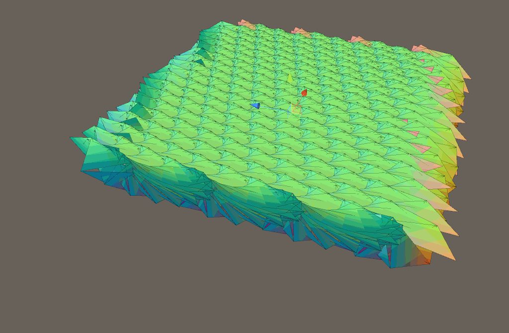
https://i.imgur.com/7QjnUHB.gifv anything larger than this and its slow for me
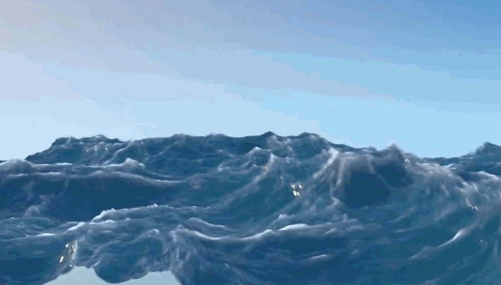
i was not expecting it to be so performant heavy
there's a reason most oceans use Gerstner or something a little more performant. 😛
yeahh but sea of thieves managed it
i don't know how
they must have found some ways to squeeze performance that they refused to share in their paper
i might email them and see if i can get a reply
v. unlikely how ever they will reply 😛
Unity Forum
I'm looking for a full ocean shader, similar to what is available in Quest 3D and DX Studio. I can provide additional information and examples of what...
twofox released his FFT ocean here
i have a copy it's not bad
i think there's a newer version later in the thread

GitHub
Next gen iteration of the unity community ocean shader - eliasts/Ocean_Community_Next_Gen
yeah that's it
ill take a gander see what he is doing in his
oh that uses c# for FFT
🤢
that surely isn't faster than vertex shader =/
ah they used look up tables
that could be faster
kinda difficult to really know
yeah it's been a long while since i ran it, i forget what kind of perf it had
doesn't seem horrible but
it honestly doesn't look that great either
yeh i mean most of their resulting pictures dont seem to suggest FFT is needed
the water is so calm in nearly all examples 😛
ive not delved into their code fully im wondering if they have not included choppiness and dispersion equations into it as that might explain it
yeah
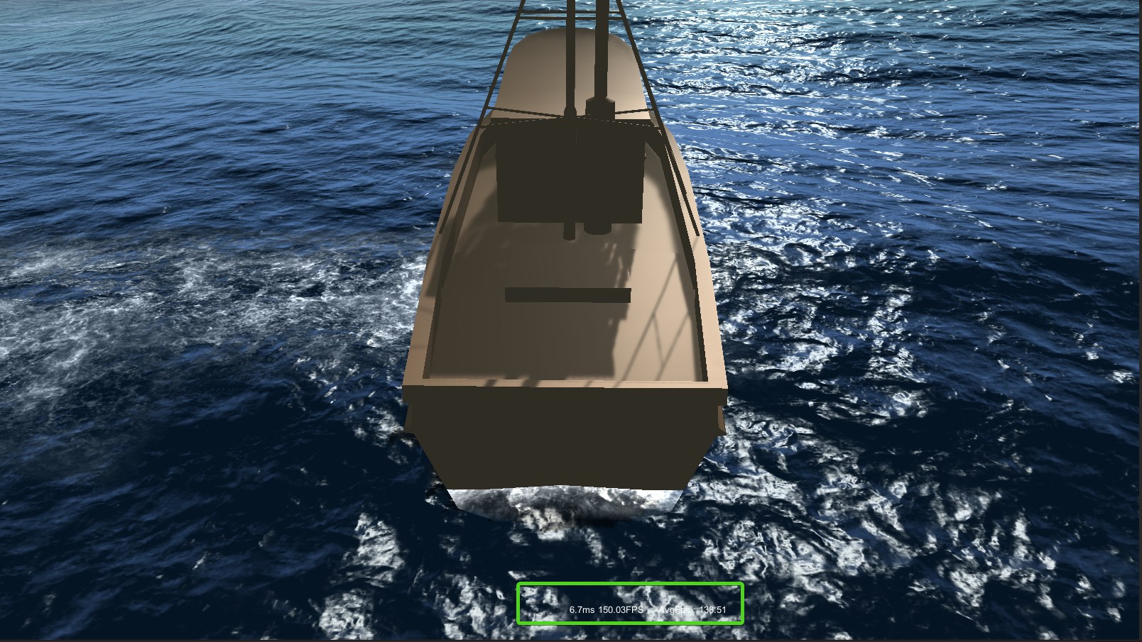
what do you mean by you're using vertex program for it? as in you just have a giant super dense mesh? Or are you actually using tessellation?
its less dense the further from the camera with tesselation @still carbon
ok good just making sure lmao
but even tesselation adds overhead so ill make one in blender at some point
as a fixed mesh and move it with camera
you'd still want some tessellation, too dense of a base mesh is a performance hit as well, gotta find a balance
how so ?
well, if on a fermi or later nvidia gpu, it has some dedicated units for tessellation, so those are just going to waste if you're going to work with a super dense raw mesh. Plus tessellation can focus detail where it needs to be even if you're rotating your camera different ways, which you're not going to get with a high density mesh
you can also form better levels of detail/quality settings when doing the deformations through tessellation or compute
ah i see
honestly, oceans and bodies of water aren't that hard if you know your exact requirements and are willing to settle for compromises... assets for water will always be a bit more crap than they could be due to having to work with absolutely everything and possibly have a bunch of features to sell it rather than precisely what you wanted. So that's why I think it's worth doing your own water, and it's not that hard
Plus water seems to be the thing that scams people the most
water is surprisingly made up only of a few simple concepts
the animation is definately the harder part - at least for making it look half decent
far harder is what happens when you have anything transparent going in and out
what do you mean
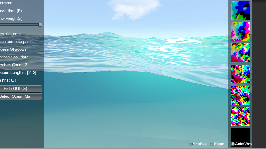
one thing ive not worked out yet is how you do above and below water at the same time
is that all done in one shader =/
when you use something like particle system it can get batched and will either mostly be on top ot behind the water
with separate rendered particles it's not much of an issue
like this
is that just one shader doing both above and below or something else
i dont even know how you know when you're under the water if there are waves
dying light has good water division like that, but GTA V prefers to onyl render above or below, masking the transition
ill have to find a paper on it at some point
so its screen based?
I think so yes
i see
the actual triangles of the water are near clipped, nothinghappens there
it's just a post effect
draws a little higher and further back than the near clip
https://youtu.be/RdN06E6Xn9E?t=2764
Watch this for water layers
In this 2016 GDC Europe session, PlayDead's Mikkel Gjoel and Mikkel Svendsen detail the techniques used to achieve high visual fidelity in the context of the...
Also generally just watch this
Crest has meniscus control like that
you could see how they did it

GitHub
An advanced ocean system implemented in Unity3D. Contribute to huwb/crest-oceanrender development by creating an account on GitHub.
pic I took from crest a few days ago
they have a camera component called Meniscus controller, that's where to look
i havent looked at how they do it, but for what its worth, its probably sub optimal
not their fault
i'm sure, I'm guessing they render the scene twice, and use pieces of both
its somewhat impossible in builtin renderer
but I haven't looked at it yet either
yea, im also guessing they render the entire scene twice and composite
when you should really write this functionality right into the renderer
a damn good use case for SRP...
i will look to see what they do, since i'm thinking about it
(and eager to procrastinate 😛 )
yeah i see
Pass
{
// The ocean surface will render after the skirt, and overwrite the pixels
ZWrite Off
so they draw the underwater first
then the rest of the scene on top
// Goal of this vert shader is to place a sheet of triangles in front of the camera. The geometry has
// two rows of verts, the top row and the bottom row (top and bottom are view relative). The bottom row
// is pushed down below the bottom of the screen. Every vert in the top row can take any vertical position
// on the near plane in order to find the meniscus of the water. Due to render states, the ocean surface
// will stomp over the results of this shader. The ocean surface has necessary code to render from underneath
// and correctly fog etc.
            // Potential optimisations (note that this shader runs over a few dozen vertices, not over screen pixels!):
            // - when looking down through the water surface, the code currently pushes the top verts of the skirt
            //   up to cover the whole screen, but it only needs to get pushed up to the horizon level to meet the water surface
hmm yea makes sense
pretty clever considering the constraints
but definitely suboptimal
well floating between up and down probably isn't where someone would spend most of their time
hopefully it's better once you're fully up or fully down
@frigid zinc you mean they have two camera for underwater?
no
they have that controller on the camera and it pulls up a curtain like they describe there in the comments
pulls it up to the boundary, draws the underwater, then finishes drawing the rest of the scene overtop
i was wrong the curtain controller handles that
and the meniscus controller actually handles drawing the thin line between
it's a pretty light shader just gives it that 'water on glass' look at the border
im trying to visually understand those comments
yeah well best to just look at the code and shaders
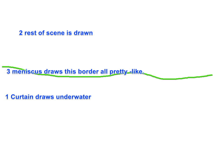
my lovely diagram ;p

a meniscus is a curve formed due to water's surface tension
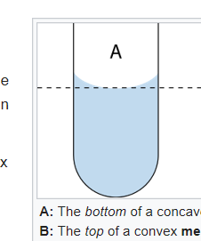
the little lip of the curve causes a distortion at that point
so they are replicating that so it looks more realistic
ok i understand that part
so they apply the post process on to that mesh only ?
or are they doing something different
oh wait, is it basically like a vertical sheet or water?
then using depth textures and the like - similar to the actual surface of the water
yay, this is finally happening https://github.com/Unity-Technologies/ScriptableRenderPipeline/pull/3060

GitHub
Purpose of this PR
Take advantage of async compilation for the preview shaders (no more "Compiling Shaders..." dialog!) and render previews only when necessary. Removes the ÜberShader so ...
those stalls after each change in SG has been pretty annoying
Cyan dreams
and marctem spaketh, and low, the pink was replaced by cyan, and the shaders did compileth asynchronously.
And there was much rejoicing
Sorry to disappoint you but they don't turn cyan :P
Each node has its own preview shader so they're super small. The update is so fast that a flash of cyan was annoying. I think we just don't update the preview until the compile is done.
sounds like a plan
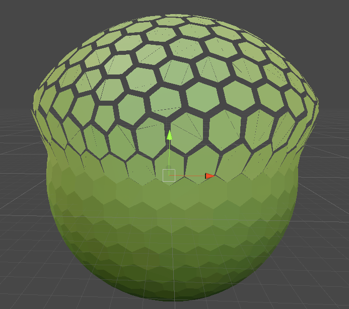
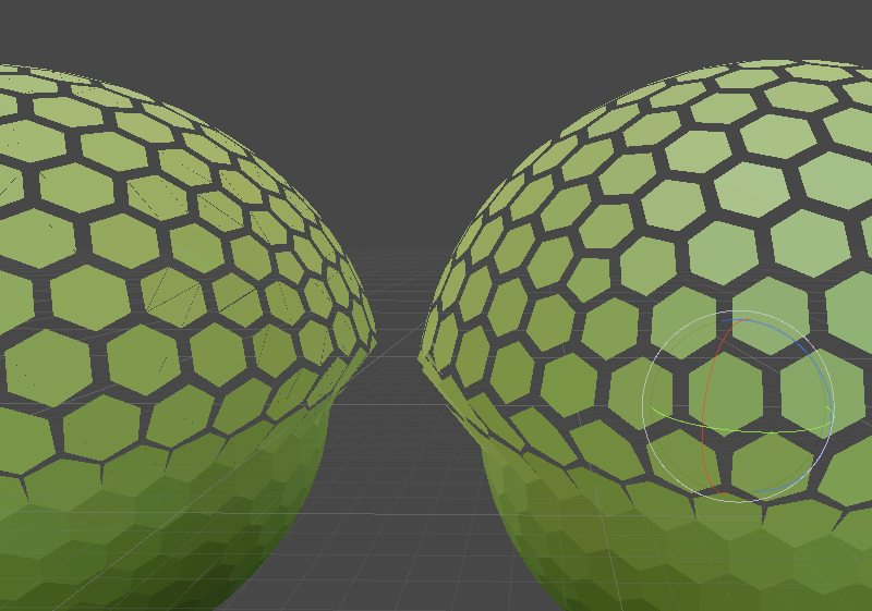
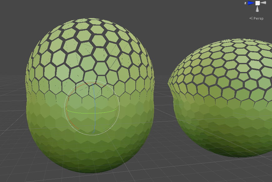
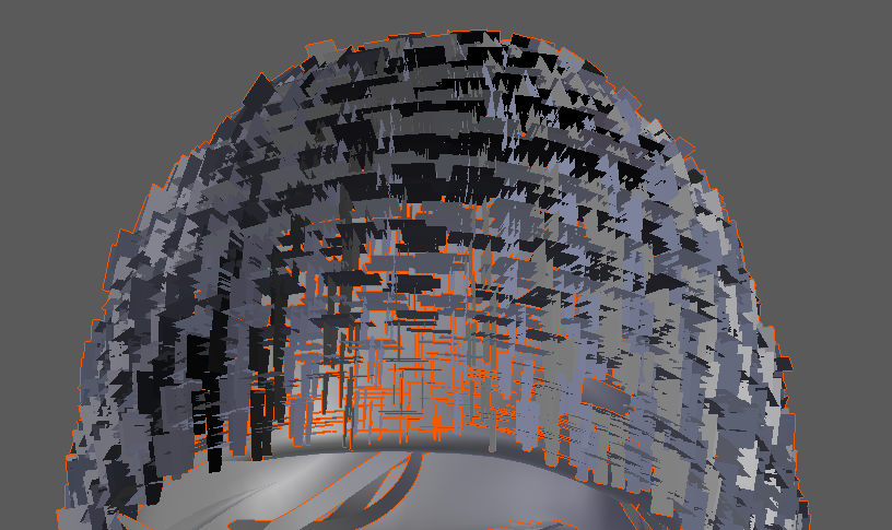
so i'm messing with a shader that uses vertex offset, but I find as I move these faces out, they break apart at the seams
is there something that can be done about that?
I mean, I want it to break apart between the hexagons
but the faces that make up the hexagon split apart
and I don't want that
would leaving each face an Ngon prevent that? I wasn't sure if unity could handle 6 sided faces
Nope, all triangles
But it should work as its normals based
so your normals are slightly off?
maybe i'm not sure
i'm using UV position
maybe UV precision isn't that great
vertex to vertex
yea maybe its an FP error in the UV?
or your UVs arent welded
something is wrong lol
out of interest why UVs for this? unless youre not pushing them outwards in the end
looks like you are right now 😛
yea but you could do that with normals and object position

Unity Technologies Blog
We created an example interactive vertex displacement effect with Shader Graph and the Lightweight Render Pipeline to help you use these features to design...
yeah i'm on std pipeline so using Amplify 😛
something like this
if youre on amplify dont add it to object position at the end (SG is absolute vertex position input)
you'd also think amplify would have example for this
they got tons of samples shipped with it
lazy, learn to do it yourself 😛
well I am :p
I was just curious about this split face thing, it does seems to be UV precision
wouldnt be suprised
well I learned something new. I figured if they looks welded they are :p
oh god no 😛
but apparently not
and you pay for those extra UV vertices
granted its just vertex attributes, but every little helps
doesn't ever vertice have it's own set of UV coordinates anyway?
or are you saying if two vertices share the exact coordinates, they share those coordinates?
i really had no idea, it's neve been factor that impacted anything I did
at least that I knew of 😛
haha yea probably wouldnt have been
but this is a good example of why 3d art fundamentals exist 😛
yeah, i'm 100% self-taught when it comes to 3d modeling
so i'm sure i'm missing a few fundamentals
always good to spend the time on proper UV wrapping and welding and packing, if nothing else than to learn what’s good and what isn’t
then you can judge the quality of auto scripts that try to do it for you :p
yeah i mean I'm strong with a lot of things, unwrapping included.
but this weld factoid escaped my notice hah
can't say I've ever seen it mentioned anywhere
so many things like that, almost never mentioned
maybe it's so fundamental people think it goes unsaid lol
it often comes up when talking about baking normals
as you want split edges when baking hard edge normals
but you want as few shells as possible really for mesh optimisation
so its a trade off ya know
yeah I mean i do often weld vertices when i'm playing with them by hand
but i just saw it as an expedient way to line them up
i figured if i didnt' touch them they were fine
but i'm guessing the 'relax' function must have undwelded them
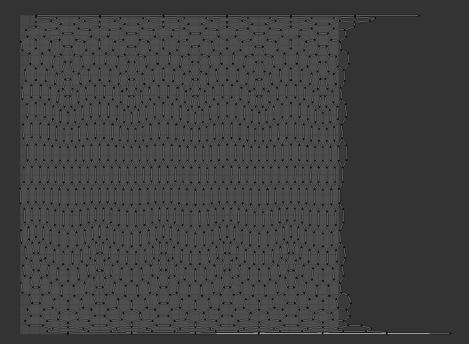
it's something i don't use much but i wanted to get this hex UV map to fit nicely in the texture rectangle
understood, im facing similar tasks
but im procedurally generating mine so its a bit simpler in this case
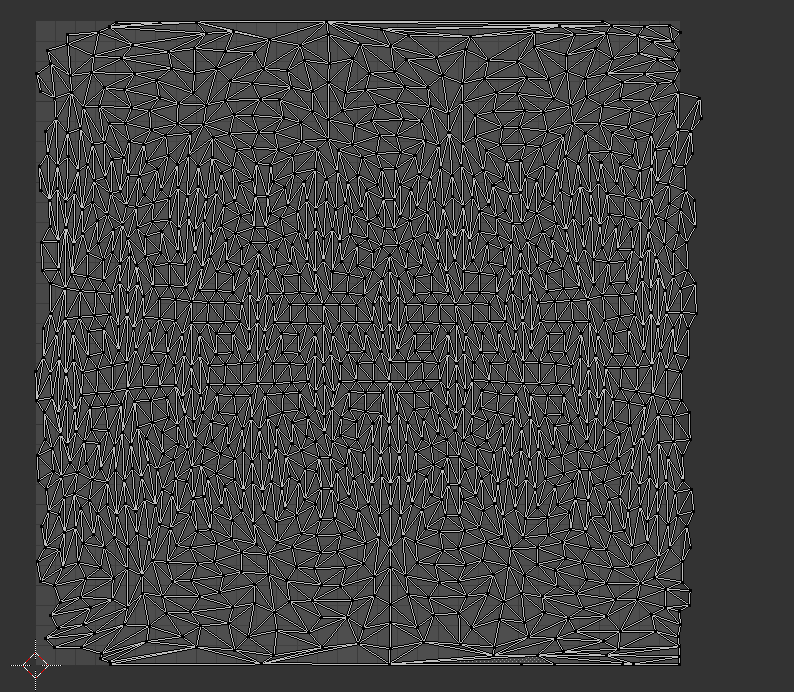
JESUS
imo you should still switch to normals
i was using relax to get the cells the same size
this is just a waste of texcoords 😛
well it still needs to be uv mapped for other reasons
yea ok, if youre going to texture it with these UVs anyway
yep
well it will have a gradient running up it as it does it's thing
so triplanar won't really do the trick
ok but if its just a gradient then why not just sample that with the object position as well?
that's a good point, probably could
i will try some stuff and see, now that I've fixed the faces splitting
but i guess i'll have to try implementing a non-UV way of doing it first hah
Vector1, really? 😛
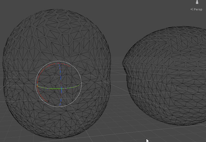
so your example works but
splitting still happens on the bad mesh with your setup
so i guess it wasn't the nodes after all, just something about the mesh
:/
there is one other difference between the meshes, i exported the bad one pre-triangulated, and the good one i left as Ngons, and let Unity handle it
so that may be a factor too
Unity still triangulated it, so i dunno, head scratcher
yep, somethings up with that mesh...
i appreciate the assist though, I learned quite a few important things 😃
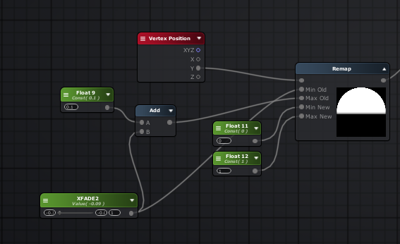
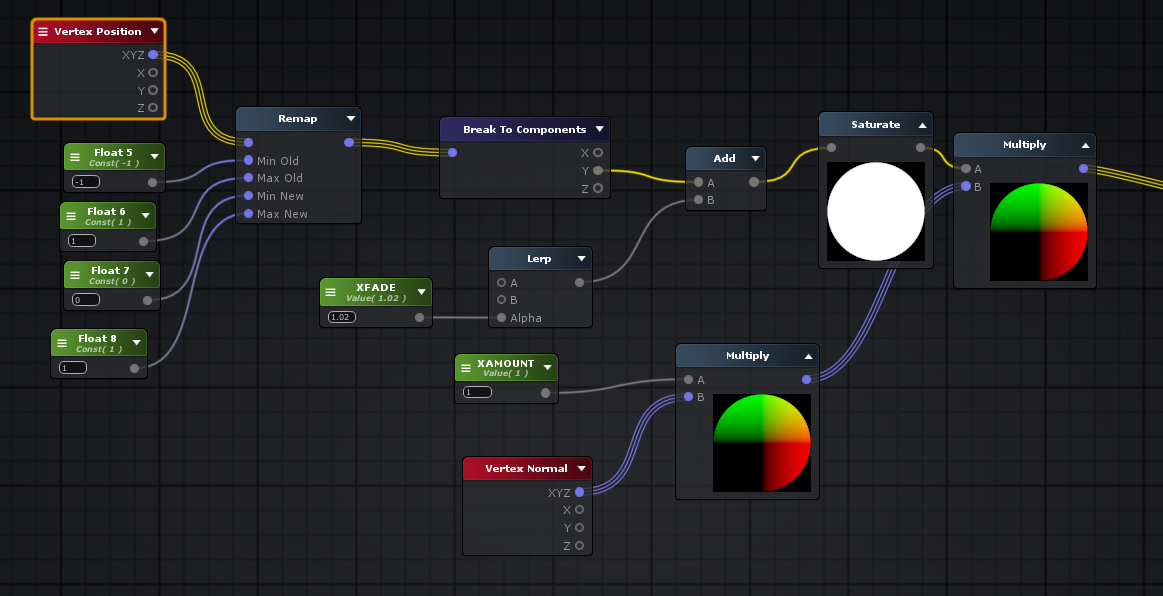
this is how I do the remap and fade though to get that mushroom look
yours wasn't much different than mine, only i was using UV instead of Vertex Position 😉
you can plug it's output directly into the saturate
yep makes sense
the normals on that mesh are flat so the verts are gonna be split
you'd either have to switch to averaged normals on your model and calculate flat shading in your shader, or bake softened vertex normal directionality into vertex color or a uv channel
though since it's a sphere... maybe you could get away with just calculating angle of vert from mesh center and offsetting based on that direction..
oh I didn't read back far enough.. your issue was just the minor splitting within the hexagons.... That could still be because the edges inside those hexagons aren't all soft-edged. I'm guessing you ran a harden edge/normals across the whole mesh instead of just the edge perimeter of the hexagons?
ok boyos
I return to the world of Shaders for another round o' mind fuck
I'm basically looking to make a shader where intersections end up taking on a fresnel effect
like ths
I have a graph currently made by I believe 0lento a bit back
which currently looks like this
but I'm having trouble with changing the color
changing the color of just the intersection glow or the fresnel color too?
Well I'd like them both to be the same
ok well then all you'd need to do is change the color value on the master node in that graph to do that
the intersection glow should really just look like an extension of the regular fresnel glow
the albedo or admission?
albedo
because I've tried to change both and no dice
all your graph is doing is changing the transparency, and what happens to areas that aren't transparent? they show they albedo/emission, or if highly glossy a reflection (which wouldn't be the case here)
make sure you're changing it on the actual material and not in the master graph, master graph is just the default color it would start with
make a color property on the left and plug it into your albedo
and make one for emission too
alright i'll give it a go >_>
oh uh actually just one more thing in the meantime
how would you go about making arrows like these?
from MTG Arena
something something line renderer?
does it matter if I set the color as HDR?
the improved line renderer might get you something close to the blue one, but vfx graph might be better equipped
and set what to hdr?
though could probably make a shader that simply draws the line on a plane, calculating line width in screen space instead of UV space
and can just scale the plane with its pivot on an edge
so I've got this strange behavior at the moment
where albedo changes the main color
but emission seems to only change the back intersection?
and if you make the albedo black?
dunno, what pipeline are you using? maybe K3D will know
lightweight
also if all you're using this shader for is that effect i'd suggest changing your PBR master node to an Unlit one, as there's no reason for it to be dealing with PBR lighting, it's just using emission
can I do that within the same graph or do I need to make a new one and copy/paste it all over?

yeah only issue is that it doesn't seem to be overlaying your sprites, unless that's how you want it
hmm?
notice the red color isn't on top of the characters? they appear on top of your bubble at all times
uhh probably, dunno if you can increase the render queue on your bubble shader to get around that in lwrp, i havn't messed with lwrp too much
@steel notch it's not an issue with the shader I made you pretty sure, it seems to just be due to the transparency sorting with the sprite renderer you use for the characters. If you lower the order in layer of the characters you'll see the sphere overlap them
couldn't I just change the order of the sphere too 🤔
oh... wait
meeeeesh
can I do something to the spheres though?
the characters are ordered specifically relative to other things already
if you click on the material for the glow shader you can change the render queue on that
increase it
just like 10 or 20 more should be fine. 3000 is where transparency queue starts.
I increased it by 1000 and they still appear in front unfortunately
its k though, its a low priority atm
it worked fine for me :S did you make sure to click away from the render queue input box to initiate an update of the values?
also to truly sell the effect you'd want two different materials of it on the glow sphere, first one would only render back-faces at normal transparent queue, and then second material would render just front at a slightly increased queue, so the sprite would actually overlap the rear of the bubble but not the front
bruh do you work professionally in gamedev? What are you? I feel like I've asked this before but I forget.
I know you modelled before (that Lizard)
I do freelance work yeah modeling/programming/shaders
it's no problem, helping others helps keep yourself sharp on topics and often learn little things here and there 😃
How much do I need to pay for a realistic hair shader that works in LWRP? 😄
can't you port the HDRP's hair shader for it?
altho I do admit I haven't checked how complex it is
It doesn't seem like it is possible right now to make a a toon shader with HDRP and SG without making custom nodes. Does this sound correct? Am I missing something?
LWRP shaders are not toon shaders.
They just do not use compute shaders like HDRP does.
Sadly HDRP shaders do not convert to LWRP. (Or the other way around)
One would think they should, but the choice was made for whatever reason to create a split between the two.
Custom nodes are very much necessary. I am using some nice skin nodes for LWRP.
https://assetstore.unity.com/packages/vfx/shaders/nodes-for-shader-graph-124611
However not many bother to make any since they are still in Preview.
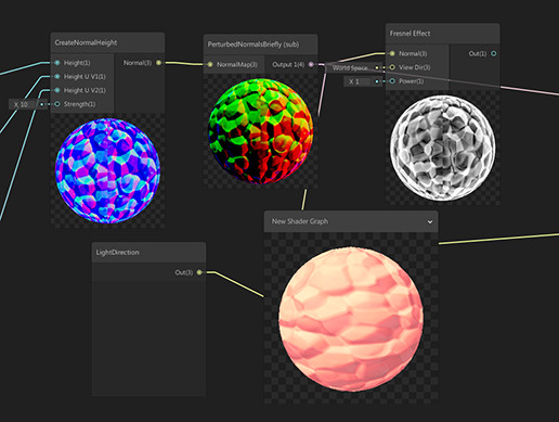
14 Nodes:
- SSS Color,
- SSS gradient,
- Parallax mapping,
- Parallax Mapping iterrations,
- Parallax Occlusion Mapping,
- PerturbedNormals (World normal with NormalMap),
- FixedViewDirectionTangent,
- CreateNormalChannel (for individual texture channels),
- Crea...
yeah cause there's no curvature haha, i'd create a different shader that swaps out the view angle glow with a height based one
just Position node, in object space mode
take the Y component from it, add +1 and divide by 2, then put it through a One Minus node and use it to adjust transparency by plugging it into the A slot of that final Maximum node
yeah
yep
kk
errrr
it lost the intersections too
honestly instead of this transparent color I'd just like the edges to have the same look as when it was a circle
well you'd probably want a power node after the one minus so you can increase the vertical gradient falloff, and you might want to instead of using Maximum use Multiply or Add
yeah use add not multi, cause with the depth fade it's going to end up overriding the other one with its 0 trans
ahh yeah the effect isn't going to work well if the cube is penetrating ground that much
if you had a script on the object feeding the world space Y value of the surface under the cube into a float parameter on the material it would make the effect fairly trivial though, nice consistent, non-screenspace-derived value to compare to
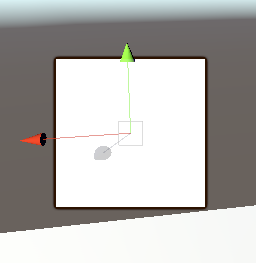
hey, I am trying to draw a billboard, orthographic sprite into a world that uses a perspective camera
is there a way for me to alter my shader so that the sprite gets drawn correctly as I pan the camera around without changing my camera to orthographic?
Here is what my billboard sprite currently looks like with a perspective camera
well that's what a billboard does. It keeps the same rotation no matter camera angle
i.e. always facing toward caemra
if you want it to stay still when you rotate the camera, you shouldn't use a billboard
right, but i'm not rotating the camera here, just panning
it's the fact that the camera is perspective, it's a distortion
i had this with a few attempts at billboards
if i switch to orthographic, the billboard lines up no matter how I pan
but I don't want to use an orthographic camera if I can avoid it
are these 2d sprites?
are you using shadergraph to do your shader or something else?
i just wrote the shader myself
good because all the billboard shaders i have are written by hand LOL
let me pull up my project and look at them, i forget which works right
in this case I probably followed an example, I'm not a from scratch shader wizard

i am sure this is the relevant part, but am not an expert in knowing what all of the shader macros do or are for
this is basically the problem, as i rotate to the left, it's like that
but as I rotate to the right:
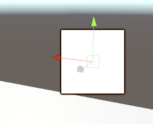
you want it to stay the same relative to the 'terrain' at the bottom
i'm lost then
it's at a fixed rotation
straight panning shouldn't alter anything
when I pan the camera to the left and right, and the sprite appraoches the edges of my screen, the perspective camera draws the terrain differently due to the distortion of the perspective camera
yes perspective.
yeah, I was to add perspective distortion to my billboard, basically
i don't think you can have both
either it's going to be drawn in perspective, or as a billboard
i wonder how the many JRPGs that exist do their games with 2D sprites on 3D backgrounds
you can try my billboard shader and see if it's any different
but i don't think it will be
sure, I'd like to see your code at least
it's a standard surface shader but as a billboard
just diffuse, no normal or metallic map
but it does have sliders for smooth/metallic
looks like we must have started with the same example shader
dunno about that, i made this by trial and error lol
still has some of my attempts commented out
your commented out attempts are the same code as my shader
i don't remember where or when I started with my shader, though. it's been awhile
well it's not like there's a lot of ways to do it heh
the one i found by searching used a script on the camera
same indentation too, I mean
and that really wasn't acceptable to me
and properties _ScaleX and _ScaleY
maybe I found an old shader you shared somewhere 😛
yes those are common in a lot of examples
i taught myself via the internet, so i'm sure i saw a ton of examples like that hah
anyway, yes i don't think you're going to get what you want, because the two concepts are diametrically opposed.
billboard is meant to ignore perspective

Game Development Stack Exchange
I use the standard approach to billboarding within Unity that is OK, but not ideal:
transform.LookAt(camera)
The problem is that this introduces distortion toward the edges of the viewport, espe...
someone here is asking the same question you are.
it's unclear if any information there is helpful but worth reading
i just found this too
it's possible I want viewpoint billboarding instead of viewplane
that post is interesting. it sounds like what you want is the World Oriented Billboard
which is a new one on me really
yeah, they also just call them imposters
they don't explain how it's done though
but at least we know a name now
i'm guessing instead of orienting it to the view plane
it would be oriented to the camera position
may have found something here

Whether you’re building a space-based game or something closer to home, assuming it’s in 3D, you may find yourself needing to render lots and lots of objects that don’t necessaril…
he's doing stuff with corners though that I probably don't need
yeah, he's doing scaling with UV2 and applying it in the shaders
unfortunately doesn't seem to be what I am looking for either. hm
could you post a video clip of something you know performs the way you're trying to replicate?
that shader doesn't quite seem to work
almost
it assumes the camera isn't rotated
as soon as you rotate the camera it breaks
sure, one sec
yeah, I was going to look for the camera's relative Y-axis instead of the world y-axis
but if your camera has no Y rotation you could try it
this is where it uses the world-space Y axis
float3 A = cross(UNITY_MATRIX_V[1], N);
at least I think it is
here is the behavior I want
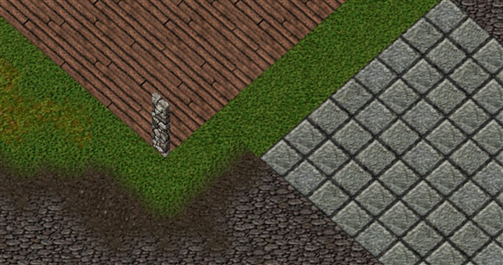
it's a 2D billboard in a 3d scene
it's still essentially an isometric view though
and he wants the billboard to angle with perspective at the edges of the screen
yes, it is
just as the terrain does
I want the camera to be a perspective camera, at an orthographic angle
the surface doesn't appear to be wwarping to perspective either though?
it all appears to be flat
it's not because it's an orthographic camera
i wasn't sure it could be done, but there's a type of billboard call a world-oriented billboard that might do the trick
you asked for how I wanted the sprite to look
however finding an example is proven hard
so you want the effect of the pillars, but with a perspective ground..
i can record a perspective camera too
about halfway down the page they discuss it
it's basically a billboard that faces camera location, not the screen plane
'viewpoint oriented' as they put it
at least we think that might be the answer
Here's an example of it looks like with a viewplane billboard and a perspective camera
which is what I am trying to avoid
i actually just remembered
the script based version i have does exactly what you want
it was why i didn't like it heh
pretty much yes
haven't looked at that in a long time, can't recall how it looks
with "AlignNotLook" on it behaves like the shaders
but with it off, it rotates to face the camera
which sounds like what you're after
nah, this thing is too extreme
well that's going to be the problem, no solution is going to perfectly match the perspective of the 3d elements
the real solution is to pick a style
either go full 2.5 Orthbgraphic
or full 3d perspective
i.e. either make the terrain a perspective drawn texture
or make the wall a 3d cube with pixel art on it
trying to mix the two is only going to leave you unhappy i feel
i feel like certain JRPGs have had 3D maps with 2D, isometric characters sprites on them for ages
with using a perspective camera
if you don't mind being restricted to shader model 4 and up, you could perhaps rotate towards camera view and use noperspective interpolator semantic on the vertex value of your v2f struct in the shader
i have been trying to keep it in shader model 3.5 for webGL
i think 3.5 is the webgl limit
but I'm not entirely married to it
what is the noperspective interpolator?
oh, i would do this on my map?
on the billboarding sprites
unless you don't want perspective distortion happening to your map either
perspective distortion is not happening on the billboard sprites though, right?
that's the problem
it needs to happen
it's happening on the map, but not the sprites
I coulda sworn this conversation started off with you asking to not have that happen on those pillar sprites, alright

i understood it as he wants the perspective shift to match
I asked if there was a way to draw the sprite "correctly", which was vague. But by correctly, I meant with perspective distortion.
but not having it would probably be an equal solution
well if I did not have it on the map...I don't know how that would look, heh. Can't visualize that.
like orthographic lol
feels like everything would be orthographic, yeah
the shader would have to not only factor in the camera position, but the object's position too
i just can't get past the part that's basically drawing it with perspective, but you want a billboard
here's an example of a game that uses 2D sprites on a 3D map with a perspective camera

Welcome one and all to another series that touches back to my memories. Final Fantasy Tactics is probably the second RPG I ever really played, so once again ...
those sprites aren't being perspective distorted though, and the camera has no actual perspective I don't think
well sure you can do that, but they aren't trying to match any perspective rotation
they are just changing the sprites based on view angle
so you see side, front, back etc
of course, I know they are switching sprites depending on which way they are facing
what i'm saying is, their 2D sprites don't look like they are floating around when they get near the edges of the screen
but yes, whether or not they are using a perspective camera I can't prove, I can only postulate that it looks like the 3D map has parallax based on shots like this moment
it's 2.5 D view. i think basically the camera is orthographic
let me see if i can replicate that
one minute while I make a gif of the camera shot I am talking about
that does not appear orthographic to me
it does to me
it's just rotating around the scene
orthographic doesn't mean it has no perspsective
it just means it has flat perspective
or maybe i use the wrong term
not orthographic
isometric
i'm not sure of the difference myself. Unity uses the term isometric in the scene view, and orthographic in the camera inspector.
but you're right, their camera could very well be ortho/iso
chug chug, (big gif)
ok first half is perspective
then i flip it to isometric
isometric basically has no perspective
but it's still 3d
hehe
well the video you provided looks a lot like isometric to me

Unity is the ultimate game development platform. Use Unity to build high-quality 3D and 2D games, deploy them across mobile, desktop, VR/AR, consoles or the Web, and connect with loyal and enthusiastic players and customers.
there's some info here on how to make the game camera isometric
you can give it a try and see what you think
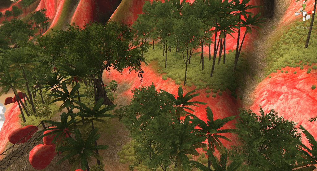
(brownie points if anyone knows what the pink island above is from 😛 )
unity's old island demo?
yes lol
came from like, unity 3
i figure most people haven't seen it
i made that iso camera like on the page, works pretty sweet
i already did have a camera set up at an isometric angle
but I still haven't tried their method
thanks for talking things through with me
I wonder why in the world PPSV2 has initial and final passes?
Can't it operate on the main camera RT?
And on that note, final pass is not rendered if only the Uber shader is used
What's the deal with that?
It seems like an obvious performance waste regarding fillrate
Well, I get it, final pass has stuff like dithering and such, that's why dithering is injected into the uber shader in case if there are no effects afterwards.
Why is the initial pass required though?
looks like you're trying to use a LWRP master node in HDRP, or a HDRP master node in LWRP
or you don’t have a render pipeline assigned at all
or shadergraph is incomplete and has bugs
that would be most unlikely alternative here
(for that error I mean, but it does have bugs)
or the earth left it's axis and we all gonna die (now that's the most unlikely scenario 😛 )
The Earth screamed, a sound all heard because it was the sound of a world being torn by gimble lock, a terrible and final end for mankind in it's pathetic little simulation.
fatefully just moments before, the earth had escaped total annihilation when a large comet went right through it due to not having continuous collision detection on.
please don't summon the Kraken
this isn't totally shaders, but is there any way in c# to efficiently copy a smaller texture into a larger texture
summons kraken
i'm sure there is, i see enough texture atlas creators and sprite sheet packers around

GitHub
Texture atlas creator for Unity. Contribute to maxartz15/MA_TextureAtlasser development by creating an account on GitHub.
like that one
Graphics.CopyTexture if supported
i had such a headache with texture atlas
used to have the edges of different textures bleeding across
annoyed the shyte out of me
the issue is that i want to copy a 64x64 into a 515x512 and the program is hanging
which is weird, because looking at this repo this is basically what im doing
well just think of it like a grid of textures
repo:
           for (int x = 0; x < texture.width; x++)
            {
                for (int y = 0; y < texture.height; y++)
                {
                    Color pixel = texture.GetPixel(x, y);
                    int posX = Mathf.FloorToInt(x / ratioWidth);
                    int posY = Mathf.FloorToInt(y / ratioHeight);
                    texture2D.SetPixel(posX, posY, new Color(pixel.r, pixel.g, pixel.b, pixel.a));
                }
            }
            texture2D.Apply();
me:
for (int i = 0; i < Terrains.Length; i++)
            {
                Clog.L($"handing texture {i}");
                var t = Terrains[i];
                var tilemapdim = t.tilemap.texture.width;
                //blit the textures from the tilemap onto the max size texture
                var newTex = new Texture2D(512,512,TextureFormat.ARGB32,false);
                var newCol = new Color[512*512];
                var tilemapCol = t.tilemap.texture.GetPixels();
                Clog.L($"color length {tilemapCol.Length}");
                //populate with offset colors
                for (int tc = 0; tc < tilemapCol.Length; i++)
                {
                    //0,0 top left
                    var colorX = tc % tilemapdim;
                    var colorY = tc / tilemapdim;
                    newCol[(colorY * 512) + colorX] = tilemapCol[tc];
                }
                // Graphics.CopyTexture(Terrains[i].tilemap.texture,newTex);
                Clog.L($"setting pixels for texture {i}");
                newTex.SetPixels(newCol);
                newTex.Apply();
                // Texture2D terrainTexture = Terrains[i].tilemap.texture;
                textureArray.SetPixels(newTex.GetPixels(), i);
            }
are these textures procedurally generated before hand?
if not why not just make the atlas in photoshop
ok well its simply applying colour data based on a grid. are your textures all 64by64?
no - the issue is that the incoming textures can be 64x ,128x,256x,512x
oh
so im trying to build a 512x512 texture array
i mean most texture atlas' are usually uniform
and then "resize" the incoming textures to be 512x512 as well to conform to the array
its more tricky when they are not uniform as you'll need to remember what you already added
actually maybe i can jsut use this? https://docs.unity3d.com/ScriptReference/Texture2D.Resize.html
GitHub
Texture atlas creator for Unity. Contribute to maxartz15/MA_TextureAtlasser development by creating an account on GitHub.
this is the core of their texture reading/writing
so yeah they use readpixel setpixel
yeah thats where i pasted the above from
well shit this seemed to at least maybe work??

GitHub
Unity – generate SpriteSheets at runtime! Contribute to DaVikingCode/UnityRuntimeSpriteSheetsGenerator development by creating an account on GitHub.
another one
        var newt = new Texture2D(tilemapdim,tilemapdim,TextureFormat.ARGB32,false);
                newt.SetPixels(t.tilemap.texture.GetPixels());
                newt.Resize(512,512);
                newt.Apply();
basically blit to a new texture of the same dimms, resize, then apply
it also skips needing to forloop over 512x512 indices X number of times
seems mostly the same, setpixel32/readpixel32
just using the 32 bit variant
GitHub
Unity – generate SpriteSheets at runtime! Contribute to DaVikingCode/UnityRuntimeSpriteSheetsGenerator development by creating an account on GitHub.
yeah seems to be the way
its not rendering "right" yet, but the program isn't hanging anymore and im not getting array size errors anymore
oh wait
After resizing, texture pixels will be undefined. damn
hmm
so you have to resize first
and if you want to upscale a small texture i guess you have to do it yourself during the copy process.
like if source is 64x64 and destination is 512x512, you'd need to write every source pixel 8x8 times
looks like someone found this limitation and made a solution
thank god it has a C# version down the page
someone else made a GPU based version that's faster (and quite a bit simpler)
oh i see what i was doing, my shit was hanging because i was incrementing the outer for loop, not the color one -_-
the issue is that i don't actually want to "scale"
i basically want to increase the texture "canvas" size but keep the pixels in the same place
yeah then might be best to just make a new texture and copy the original into it
is there a way to "shave off" certain sections of a mesh with shadergraph?
like if I have a sphere and want to turn it into a hemisphere
this is a pretty cool package showing how to use a plane as a 'cross section' viewer for 3d models
obviously it doesn't use shadergraph, but the same technique could be created in shadergraph
@frigid zinc as a follow up, i just ended up making multiple terrainarrays on my shader lol
ah I see.
its prob more efficient anyways - in the resize system you needed to have a single 64x64 sprite you had to store a 512x512 tex in memory
well glad you found a solution 😃
👍
rip
UNITY_DECLARE_TEX2DARRAY(_OnesSpriteArray);
            UNITY_DECLARE_TEX2DARRAY(_TwosSpriteArray);
            UNITY_DECLARE_TEX2DARRAY(_FoursSpriteArray);
            UNITY_DECLARE_TEX2DARRAY(_EightsSpriteArray);

            fixed4 frag (v2f i) : SV_Target
            {
                // float FOG = i.color.r;
                float FOG = i.fog.r;
                fixed4 col = fixed4(0,0,0,0);
                if(i.color.r == 0.2) //64 - ones
                {
                    col = UNITY_SAMPLE_TEX2DARRAY(_OnesSpriteArray, i.uv) * FOG;
                }
                if(i.color.r == 0.4) //128 - twos
                {
                    col = UNITY_SAMPLE_TEX2DARRAY(_TwosSpriteArray, i.uv) * FOG;
                }
                if(i.color.r == 0.6) //256 - fours
                {
                    col = UNITY_SAMPLE_TEX2DARRAY(_FoursSpriteArray, i.uv) * FOG;
                }
                if(i.color.r == 0.8) //512 - eights
                {
                    col = UNITY_SAMPLE_TEX2DARRAY(_EightsSpriteArray, i.uv) * FOG;
                }
                clip(col.a - _Cutoff);
                return col;
                // return i.color;
            }
@frigid zinc can you post your Shader "Custom/BillboardSurface" again? The pastebin expired, and I wanted to borrow something from it to see if it works with Sprites.
for some reason my shader doesn't work with 2 sprites from the same spritesheet, and it seems to possibly be the way I calculate the vertex position
as soon as I make a 2nd sprite from the same sprite sheet that uses the same material, they both disappear
unless I zoom in really close. it's bizarre.
actually nevermind, I had your shader open in an old tab
tab hoarding for the win
hm, I couldn't get your shader to actually do billboarding
oh, it's probably because I am in LWRP
@grizzled prairie doesn't ASE have something like this?
not sure if there's any node for getting the side but you could probably figure that out with some logic
there is a node for which side is currently being rendered: http://wiki.amplify.pt/index.php?title=Unity_Products:Amplify_Shader_Editor/Switch_by_Face
@fervent tinsel I actually tried that but this is my result - https://puu.sh/CRyIZ/035f7c31c6.png

The fresnel doesnt work double sided for that effect. It was the reason why I omitted fresnel from the backside on that SG example
yeah I've made something similar awhile back, it's very doable in ASE
Sorry for the slow replies! I just tried the Switch By Face and it's closer to the end result I'm looking for : https://puu.sh/CRBCa/5c3117a21d.png

@grizzled prairie that looks like you have the wrong face for the fresnel still
unless you are going for effect like that 😃
yeah, it's a little bit backwards right now 😬
Hello everyone! Quick question, I have a custom shader, and I'm trying to update one of its parameters (a color) when the GameObject is disabled, without success.
Does the game object need to be enabled for the change to work? Can't find this anywhere
How are you checking if the color changed if it's disabled (and thus not rendered)?
How are you setting the color as well? It shouldn't matter if the GameObject is disabled, since what you're setting is a material/shader property which is a separate object from the GO.
I'm doing this:
m_image.material.SetColor(m_colorPropertyId, newColor);
And I know it doesn't work because when the GO is active again, the color hasn't changed to the newColor value
Something worth noting is that only that GO has that material, so when its disabled none other GO is using it
@grizzled prairie I did a quick test on ASE and got:
just swap the color property to vertex color on yours
you can of course add more things to the max before opacity if you want some surface effect to that
Okay, cool 😃
Hi guys, we're having some weird artifacting using ASE. In this test image (zoomed in), you can see black specs on the model when giving it an absolute barebone fresnel effect.
It's just a color into Albedo and Fresnel Node straight into Emission.
you used to get those a lot on the old Unity 4 shaders with high specular values
no idea what is causing that on your image tho
Ugh. Yeah, it's pretty noticeable, and the client definitely will too.
can you put like min node on the emissive, just to make sure there's no negative values being fed to it?
Sure, be back in a moment with results.
or clamp but min with other input set to zero would do
Nah, same issue. We did saturate the original shader too.
maybe some issue on PP then
so Ive got two sphere meshes here
the one on the left has a much higher polygon count (if thats what its called)
than the one on the right (the basic unity one)
when I apply the same material to it though
it doesnt look the same (the one on the right is correct)
what do I need to do
need a bit more information. how are each of the spheres UV Mapped? what is the material exactly? can you show the Material inspector?
so it does have a bumpy normal map
either there's a huge difference in the UV mapping of the two spheres, or there's a tiling difference (or both)
but you should be able to make a copy of the material for the small sphere, and turn up the tiling
if it's 1 x 1 try 5 x 5 or 10 x 10
I think the sphere I have is like 100 by 100 in blender
for vertical/horizontal
is that too much
ok well that would explain the difference also
how do I do that
is it an ICO sphere or UV sphere
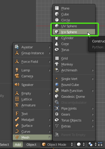
which option did you use in blender
if you can't remember can you show me a wireframe view of the sphere?
I can tell by sight hehe
each type would be uv mapped a bit differently
and we should probably go to the 3d channel since this isn't about shaders anymore
kk i'll head over to 3d
Hi, can someone help me to add this colour lerp to the default unity HDRP terrain shader?
http://prntscr.com/mqk7ts

https://i.imgur.com/JSpabtJ.gifv unintentional bug but looks cool
fluffy conveyor belt
@brave ore as I understand all the HDRP shaders are available as shadergraphs, so it should just be a matter of cut and paste, I think?
i haven't actually looked for the graphs
@frigid zinc the terrain shaders look very different from regular lit shaders.
help me a bit, where do you find the shadergraph versions?
there's no terrain graphs for HDRP yet
ahh
it does sound like that's coming eventually but it's not there today
for future reference where do they keep the shadergraph versions, in the HDRP folder?
I made the shadergraph shader my self. I need to convert it to hlsl code that the TerrainLit shader is using
(in still installing hdrp)
these are the ones we get today on latest HDRP:
ah ok
there's basically three main things missing right now from shader graph templates
- terrain graph
- ability to do tessellation on shader graphs
- layered lit graph
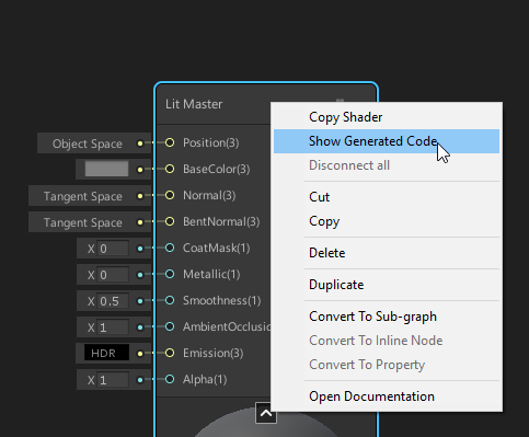
as I recall you can view the HLSL by right clicking on the master node
I am not looking for making a terrain shader in shadergraph.
altho technically the third one can be done on lit master node
I need to find a way to modify the TerrainLit shader so that it could have the a vertical world space gradient
porting that graph to shader code isn't hard part here
I know, I can make it as a Surface shader in CG code. but Terrain shader looks structurally different from a regular surface shader.
- the Show generated code is 3k lines
but if you can't point me to the shader i can't help heheh
since it's not in shadergraph there must be a shader file you're looking at. where is it?
while the desired behaviour can be written in less than 100 lines as a surface shader.

right you have to extract the part you need out of the rest
i'll have to reconstruct your node setup so i can see what is generated, give me a few min
(ugh, does it really compile every time you connect a node 😦 )
GitHub
Purpose of this PR
Take advantage of async compilation for the preview shaders (no more "Compiling Shaders..." dialog!) and render previews only when necessary. Removes the ÜberShader so ...
I actually tried that but I think I broke something on the merge as it was still as painfully slow to do new operations on the SG 😄
@brave ore, the actual code from your graph is between the comments:
//-------------------------------------------------------------------------------------
// Graph generated code
//-------------------------------------------------------------------------------------
and
//-------------------------------------------------------------------------------------
// End graph generated code
//-------------------------------------------------------------------------------------
you can mostly ignore the rest
the problem is going to be, they have each pass in an include file
so there's nothing in TerrainLit.shader to really modify
@still orbit noticed this too 😄 https://github.com/Unity-Technologies/ScriptableRenderPipeline/pull/3087

GitHub
Purpose of this PR
Why is this PR needed, what hard problem is it solving/fixing?
This PR adds the reamining Property types to the Blackboard (Matrix2, Matrix3, Matrix4, Gradient, Sampler State). T...
@brave ore it looks like the actual pass code is in #include "Packages/com.unity.render-pipelines.high-definition/Runtime/Material/TerrainLit/TerrainLitSharePass.hlsl"
it's nice to have these all exposed finally
so yeah it gets complicated to do this kind of modification
@frigid zinc so do i just pass my shader as an include?
no...
: (
it's not anywhere near that simple
the code would be somewhere in the includes
but i'm not sure where
Yea, its actually a side effect @fervent tinsel . All I wanted to do was expose all the slot value types in subgraphs
but it was easier to add the remaining property types to all blackboard and keep the code that converts property > port, than to refactor the blackboard to work differently in subgraphs
500 LoC rather than ~4000
I don't really see why one would even want to limit those out by design
@frigid zinc TerrainLitSharePass.hlsl"?
@brave ore it looks like it may be in TerrainLitSplatCommon.hlsl
but yeah, I don't really complain about the current setup once these are merged (as far as the properties go, I still got my nag list on SG's other issues :/)
but this is heavy stuff. you'd need to be a real shader exert to modify this
I'd really want subgraphs inside subgraphs really badly 😄
Well it gets sort of dicey as you cant expose them to the property block. But its less that we werent going to have them on the blackboard, and more that we eventually need the blackboard contents to be contextual to the graph type.
But backporting that work to 19.1 was deemed too risky
And yes, nested subgraphs are coming 😛
could do a lot more custom nodes with them
Yup, life should be a lot better when we land these changes weve got coming...
this is also what UE4 does for like half of their material nodes, they are just their own material functions (which is their equivalent to sub graphs here)
Oh well, thank you for the help @frigid zinc
TerrainSplatBlend(float2 uv, float3 tangentWS, float3 bitangentWS,
out float3 outAlbedo, out float3 outNormalTS, out float outSmoothness, out float outMetallic, out float outAO)
this function has a lot of 'out' variables, including albedo
you might could alter the outAlbedo inside there, but it would be a real experiment to see if it works 😃
that's the function that blends all the splats together
the properties you want to have would have to be in the top level shader
so would take some coordinating of edits to both files
;-; That is way beyond my programming abilities .
i'd pretty much be like a monkey beating on a rock with a bone myself, hoping something worked 😛
i have a good idea something would happen, i just don't know what LOL
I am more like a fish in this analogy.
😃
XD
@brave ore you could modify TerrainSplatBlend function and set outAlbedo to whatever the result is from your gradient calcs. You could also open TerrainLitData.hlsl and in GetSurfaceAndBuiltinData function, modify "surfaceData.baseColor" after the call to TerrainSplatBlend
you'd also probably want to do the same changes for the generation of the basemap shader (rendered as the lowest LOD for the Terrain). that code is in TerrainLit_Basemap_Gen.shader. The first pass there is what you would want to modify, again after the call to TerrainSplatBlend. You'd set "albedo.xyz" to your color
if you modified the TerrainSplatBlend function, you'd only have to add the changes once
sorry for X post, but I thought this fit here (and no one answered in #archived-hdrp ). Does anyone know why the text has a weird delay? 2 Cameras. First is perspective, and renders everything but the UI layer (which text and panels are on). Second is orthographic and renders nothing but UI. HDRP, happens with multiple fonts
@rotund tusk thank you for the advice, I will give it a try
anyone know why there is banding artifact in the Game render when in the scene i have no problem ?
@ornate blade I saw your previous post, but the fact is I have no earthly idea why that's like that, and I suspect nobody else does either.
if I had to hazard a guess, something to do with some camera effect you are using?
Hmm Bugger. Was hoping it was just me being dumb. Thanks anyway ceebee :)
merged this for testing 🤔
Hi there, i get an error when i use terrain tree pain to add some trees (treee must use the Nature/Soft Occlusion shader. Otherwise billboarding/lighting will not work correctl)
Im using a costume shader, why does it force me to use a other one??
because it likely has certain shader properties it wants to set on the shader to give them the full possible effects and per instance differences. Though it is strange that it would restrict it instead of just test if the shader has those properties
Is there any documentation on how to create my own master node?
Hi guys, Is it feasible to pass a Texture2DArray to a shader and "collapse" the array into a composite image? (i.e. the topmost layer overwrites the one underneath and so on). The texture size im targeting is quite small (128x128), but I need 10 layers.
If i'm understanding you correct yeah, you can loop through the array and keep adding the sampled colors of each together however you like until you've looped through
Is it that you want a returned copy of the combined texture though? or is this to be purely for rendering on an object
Purely rendering. I am preparing the texture2DArray at runtime to combine sprites into a composite from layers of outfits/appearances. The 128x128 textures is a small atlas for a single animation so the array only has to be rebuilt when the "animation" changes.
I'm currently just prototyping this, but its working through shadergraph with 5 layers by using 5 seperate sample2DTextureArray nodes each sampling incremented indexes and using the artistic Overwrite node to combine the next layer using the previous' alpha channel combined with the current alpha channel. I assume this could be optimized by writing actual shader code though...
if you wrote a compute shader for it sure, but that would greatly restrict platform support. The regular shader code SG would produce for those operations isn't any less performance than how you'd write it manually in a shader.
Fantastic. So upwards of 10 different Sampling nodes isn't something to be afraid of? Thank you for the info.
I suppose the total number of pixels of 10 (128x128) textures that the shader is sampling is still less than a single 512x512 texture.
the amount of pixels sampled is determined by the screen resolution and the area the object you're rendering is covering of it, not the size of the textures
so for each pixels your sprite is covering, each of those samplers are executing for each texture in the array
This might be a bit heavy on mobile platforms, but always best to just do a test and see how it performs
will your screen with a bunch of them
This is literally ONLY going to be used on characters. So only characters that have the option to be customized (NPC's and player character). Enemies wont need to dynamically change appearance and can be handled regularly. So it shouldnt be many on the screen at once.
yeah should likely be fine then
also keep in mind if targeting mobile, only opengl es 3.0 supporting phones can use texture arrays, not es 2.0
Thank you so much! Testing is next on my list but I just wanted to ask someone with shader knowledge if this was a bad idea. The work flow is much better than using mecanim for me, only having to make a simple editor to manage lots of atlases and a single quad for the player rather than 10 seperate spriterenderers.
Great, thanks! but this will be windows only. 😃
ahh ok no worries for sure then
The only thing that I wish I could change is I cant have any variable number of "layers" being sampled, as I have to add a sample node for each index. I guess there would have to be some sort of looping node to accomplish this.
yeah that's one way you'd be able to write it a little cleaner since you could just loop through it in shader code using the same sampler
what do you mean specifically
well im using a lot of trig functions because i use complex numbers in polar form, and im trying to optimize, so i thought about making a lut and lerping
if they already do this though then it would be a waste of my time
that's not enough to go on, what's the context, are you doing this in vertex shader or frag? you could put your complex numbers into the vert struct and let it interpolate it for you between the verts for example
well im currently using DFT and converting to FFT ideally in fragment shader
some one else told me they did it in pixel shader rather than vertex shader so i just planned to do the same
yeah most of it would have to be, but some data can likely be computed in the vertex and let the interpolator feed you the adjusted value for your fragment. I'm confused about what the lookup table would do for you though, how many different numbers are we talking about here and what kind of data would you use to determine where to grab from in the table?
You can write constants in the shader if needed which is often done when people need magic numbers
i would plan to have an array of angles every 0.5 degrees and then say i had 0.67 i'd lerp between .5 and 1 in the array. rather than actually have it compute the trig value
its the only major heavy lifting the algorithm does
besides iterating, but thats usually unrolled anyway
but i equally dont know if its warrented on modern gpus
ahh yeah that could be a performance boost, only way to know is test. That's going to involve grabbing values from an array or sampling textures though versus extremely fast inlined instructions that don't need to grab data from elsewhere.
But I guess the answer to your question would be that no, the shader compiler isn't quite that smart to know to construct some sort of lookup table from your various equations, your table would still be a fairly user defined construct using rules that only you're aware of due to knowing your needs.
ah okay thanks for letting me know, i'll look into it then 😃
Would anyone be able to point me in the right direction to creating a world space coordinate shader; just like the one that comes with the prototyping asset pack, but double sided, and transparent?
@odd pilot Couldn't you just copy that shader and change the culling and blend mode ?
That's what I am trying to figure out how to do. I got the cull Off command to make it double sided. Now working on the blend mode. How do I do that?
Check that : https://docs.unity3d.com/Manual/SL-Blend.html
In particular the "Alpha blending" part
@amber saffron Thanks very much! I'll look into that
Optionally, if the shader is a surface shader look here : https://docs.unity3d.com/Manual/SL-SurfaceShaders.html
At "Optional parameters", there's the "alpha" keyword, to auto-enable alpha blending
Whats the problem with the terrain trer brush, i cant brush because my tree has a different shader, when i try to brush it comes this error : (treee must use the Nature/Soft Occlusion shader. Otherwise billboarding/lighting will not work correctl )
The error is self explanatory. Your tree should use the proper shaders.
Why cant i use a costume one, i made
Maybe also check the terrain settings, and set the tree bilboard start to the maximum.
You can use a custom one, but you may encounter lighting issue, and will probably no have billboard working.
Can't i just inlude the code in it.
The shader i made isn't well, but thr best i could finde for pixels
Someone know what's the best shader for this tree?
Unlit ?
Then make an unlit without face culling shader ?
I say unlit because the asset you're showing already has lighting painted
You mean to edit the until shader?
Or create a new unlit shader and just change the cull mode
I tried with the unlit shader that exists already, but i have the same issue i had before
It says use only nature/soft occlusion shader
If you like i could send you the tree and try it out
got SG POM working now on latest wip branch for it 😃
Amplify Shader Editor just got this btw:
I hope SG will follow up
too bad that will not work on HDRP anymore due to PPv3
build-in PP Graph would be fancy, kinda missing that after getting used to it being always there on Unreal
yeah that's a neat addition
@rain scaffold Like I said, the nature/soft shadow is just a warning, it should still render. Not when the tree is displayed as billboard, and probably with broken lighting (but you don't care for that)
[Paid] Need someone adventurous and creative to help me with a shader compatible with LWRP in Unity 2018.3
The shader should have (if possible) an effect like microfibre for woolen cloth similar to this:
https://youtu.be/3tcVzlUbNDc?t=88
Please PM and provide a link to the best examples of your custom shader work.
Thank you.

Hey guys, it's been a while. I have been working on our upcoming animated short film called 'Windup'. And this is a test scene from it! The test scene is a c...
@amber saffron ok, im using now the shader that its calling for, the normal tree soft occlusion leaves, but the problem is it doesn't receive lightning
@dry island is that effect on the video really done in shader? I looks like manually placed cards (ok bad wording on this, meant cards in general)
Perhaps.
I have a potential other solution in mind if possible, doing it with particles.
Placing cards manually... mmm we are talking about hundreds if not thousands. Sounds very inefficient. You will also notice there is some similar effect on her hair. Therefore I assume it is some shader effect.
you don't have to place them manually, still can do proc gen on tools, in houdini etc
Yeah could be. That is my plan C. doing it with some scattering tool in 3dsmax.
yeah i'm pretty sure those are cards
if you watch the inspector closely there's 4 instances of the fabric shader on that sweater, Purls, KnitS, DetailS, and BorderS
likely one of those is for the fuzz, (Purl?)
ah seems purl is fancy stitching, so that must be the design part
those are knitting terms, knit stitches go forwards and purls go backwards
maybe detail then
therefore would be two different types of lighting reactions
yeah we're just trying to figure out the fine fuzz sticking out
who knew that my knitting obsession would be helpful in graphics? 🤔
probably mesh cards, right?
i would guess mesh cards for those yeah, probably in that details instance
nods
Possibly. It definitely is an experimental HDRP fabric shader. It says so. And there is an object called "fur_orig:Group2".
Now if this material is applied on planes, it is something we can't say from that video. I wish there was someone to let us know how this was done.
These are the kind of videos and tutorials many people need, instead or re-iterating the documentation combined with some marketing speech with nice images.
I was looking at the Unity Japan channel on youtube and the tutorials and workshops there are much more advanced compared to what we typically see in English. Too bad they are only in Japanese and there were no subs.
well i can say with 98% certainty it's cards. that's pretty much the industry standard way to do it
HDRP Fabric Graph only does fuzzy like surface with wool option
but it doesn't change the geometry
by the time that demo was presented it was separate shader
now it's ported to SG template
games with similar effects used hair cards, like this game, Until Dawn
all those cards were the 'fuzz' on the beanie
DICE uses that for moss on battlefront rocks 😃
it's cheap and effective technique

not easy to see in a badly compressed youtube video but you can kind of get the 'fuzzy' feel on the profile
Awesome. Then it is easier than I thought an won't cost me a dime! 😄
moss mapping
hmmmm, FPS Sample now has weapon FOV hack in shader graphs
also no hacked together shuriken particle shader for furnace, they've moved furnace effect to vfx graph (it was most demanding part of the level anyway due to expensive effect)
fov hack?