
#archived-shaders
1 messages · Page 104 of 1

ok today is not my day. How do I make this gradient horizontally wavy?

I'm drawing a complete blank for some reason
like I practically just wanna apply a sine curve to that line
ok I sorta managed it, am I overcomplicating this?

I deleted a node connection and unity crashed bruh
What is the end goal?
ok so, what's the name of a sine wave that's completely comprised of straight lines
essentially, I want to make this effect spiky

oh I found out there's a thing called a sawtooth wave and it looks pretty much like what I'm trying to achieve
oop yeah that's it, problem solved
Hey! Im using unity 2022.3.30 URP. I want to make a basic image effect shader. I did this a while ago with no issues but cant seem to get it workig now, how can i implement it? Dragging it in to the full screenpass renderer feature doesnt do anything... onrenderimage doesnt do anything... do i need my custom scriptable renderer feature to blit the screen or what? My shader is in CG
Figured it out.
Hello there, I'm trying to change the code to use a gradient and blurring it instead of a texture for a toon shader in Shader Graph URP Unlit

this is my current setup
I would like to use a Sample Gradient, blurry it a little bit and then use it the same way but it does not receive the same params as Sample Texture obviously
hey, does anyone here know how to use materialPropertyBlocks? I have an object and want to dynamically change its alpha, and i was just testing how the materialBlocks work and i just cant get it to work. I have this test script and it literally does nothing. I will also show you how the material is configured if that helps


Gradient objects can't be exposed to the material and usually already blend between colours so a blur wouldn't be needed - and is an expensive operation anyway.
You'd be better off keeping it as a texture. If the problem is those are harder to create, Can probably find editor tools/C# scripts shared online to generate textures from a gradient from unity's inspector / custom editor window.
_Main isn't a correct property name, you likely want _BaseColor based off looking at the Lit.shader source code.
However, using MaterialPropertyBlocks in URP is not recommended. You should set values on the material directly. e.g. meshRenderer.material.SetColor("_BaseColor", color)
(Or meshRenderer.sharedMaterial to reference the asset directly without creating a duplicate material)
Hello guys, I need to generate a simple depth map in HDRP. I have a script that screenshots the scene. Anything in the docs about this? What is a good way of doing so?
yes, but this either changes the color on all objects that use the material (sharedMaterial) or when just setting material, it instantiates a new material which is very bad for perfomance in my case, cuz i will have a lot of these materials
URP uses SRP batching which optimises draw calls even with different materials, just needs to be the same shader (and shader variant - so same keywords set on material)
yeah but the instantiation will still not be performant right? or does it not matter that much?
Idk, maybe more memory but I doubt it would affect performance that much
so i have one parent object and like 20 children objects under it that all have meshrenderers, so i made a new material on the parent object and change it dynamically how i want and then set the material on the child objects, but this changes the material on all the child objects even if just one calls it.
How does skinner mesh works? Is there a way to use both textures in order to make an unlit shader based on that textures?


i tried blend node but with no success
if i put base color, only the head texture for example is drawn in whole 3d model and i dont want that
The mesh has two submeshes, so you need to assign two materials. You should use a Texture2D property and connect that to the sample node. Then each material can have the appropriate texture assigned
the thing is that i'm doing a Outline color material which is drawn on top of the material using Render Objects
Make sure you use renderer.material, that should create an instance for that renderer so only that object is affected. If you use sharedMaterial or reference the Material directly it will change for all objects
so i have to do two materials and stack them on top is the only way?
how is this even possible to render? anyone got idea?

If you need data from the original materials you can use the "Override Shader" on the RenderObjects feature instead of "Override Material". The shader can then use the same property reference (e.g. "_BaseMap" if the original is using the URP/Lit.shader) to grab the texture.
Though be aware it won't batch objects so may be more expensive.
AO? useless, Raw geometry? only if u got 1000gb memory, normals? doesn't explain bumps + 1000gb memory
how do they render that realtime ?
thank u so much i will try it
i did, thnk u so much!

Mostly tessellation and controlling LOD. Most of those 'bumps' are not likely rendered till the camera is closer
is there a way to cast shadows in unlit shader or lit shader in a way that only effect other objects and not itself? This is because I'm doing toon shader but I want the object still project it's shadow on the floor in some way (don't matter if manually or lit)
I only use Main Light Direction for the light computation in the unlit toon shader, but there's a bottom material which is drawing the textures which I change it to unlit in order to avoid it drawing the shadows of itself
Well, if you want an unlit shader with shadows you'll need to make a custom unlit and add the shadow libraries to it and the method calls
As for self-shadowing, you can turn off receiving shadows completely which would eliminate that but you won't be able to receive other shadows. If you do want to cast shadows and prevent self-shadowing while also recieving shadows, then there's some juggling with the renderer layers (light layers / shadow layers) you'll need to reseach into
ok, thank u so much this looks a bit advance but maybe is the way to do it
low do you lod that ? also, doesn't tesselation increases vertices eitherway ?
so do u not need more memory?
also, in the video, the foot ik reacts to the very fine details
They're different chunks of meshes that are loaded at different times. Tesselation mapping / heightmapping helps reduce the overall cost of these meshes as it can be stored as a texture
i see i see, but the memory needed to render these verts remains the same as real verts no ?
and the cost ?
Most detailed chunk is rendered close to the camera, but those far back are using a lesser LOD that's less complex but because of shader magic it can appear complex
ah u mean the far things get the low mimaps of the displacement map ?
i get you
but its still very expensive to render such high count of verts
still
Stuffs actually pretty advance nowadays it might not even be chunking doing some advance texture streaming and mesh deformations
such as what
take a look into parallax mapping too, it's a pretty cool technique to fake tessellation when you further away
yea ik about it
not used here though
shadows appear really well at fine details from distance
really it's just all textures and interpolating the surface area between a handful of verts
@ebon basin idk about tesselation, i get pretty horrible results with very high vert count

maybe you mean sth else?

Medium
I’m Ned, and I make games! In this Unity graphics programming tutorial, I’ll introduce tessellation shaders and show many ways to use them!
thank you for link but is can you comment the reason u sent it ?
It very much covers what I've said. Obviously it can be expensive but the article goes through different ways to lessen it through various methods
You should watch the new gta 6 trailer
ok I know I'm completely out of this conversation but that is exactly what I've been looking for yesterday
tyvm lmao
nvm it's a pain to implement in urp
hdrp has a tessellation node for shader graph but urp doesn't that's super annoying
ok so to confirm because I'm a little iffy on something
- sorting priority means that material gets rendered before others and + means it gets rendered after right?


Posting code
📃 Large Code Blocks
Use links to services like:
https://paste.mod.gg/, https://hastebin.skyra.pw/, https://paste.ofcode.org/, https://paste.myst.rs/, https://scriptbin.xyz/
📃 Inline Code
Surround code with three backquotes. Not quotation marks.
To format as C#, add cs to the first line:
```cs
// Your code here
```
Add a comment with a line number if there is an error message.
A tool for sharing your source code with the world!
What are we even looking at? What color does it have originally?
Anyone might know why this is facing the wrong direction instead of at the camera


Seems like its inverted but i cant find out how to fix that
try return fixed4(1, 1, 1, 1) - col, 1 isn't a 4 dimensional vector
how can i get tex_texelsize in a hlsl function without passing through parameter ?
Hey, does anybody know how to get APV data in the shader graph?
Baked GI doesn't return anything
in this case
if u want to bake on runtime, my only idea is taking a render camera and a plane, if u dont bake in runtime then i recommend using blender to bake
im sorry you misunderstood me
what i mean is
the baked GI node in shader graph never shows anything other than black
i just want to access the data baked by APV
say I have global colors A, B, C. Is there a way that a single graph can point to any of those based on a per-material instance parameter?
e.g. different instances of materials of the same shader could point to either A, B or C depending on an exposed parameter
Could pass those global colours into shaders using an array via Shader.SetGlobalVectorArray, though may need to take into account colorspace differences - (by using .gamma on the Color object on the C# side iirc?)
In graph would use an exposed float property, as input to a Custom Function node to declare & index that array. https://www.cyanilux.com/faq/#sg-arrays
But tbh, if you're exposing a parameter anyways, kinda feel like you might as well just expose a Color one. If you really need global colours can probably find a way to handle that on the C# side instead and set the color property with material.SetColor(...)
Hey has anyone experienced this before? This white glow and black mesh is happening with any shaded material? This object was generated with code and it does not happen with normal meshes like the cube or plane. Is there some normals or uv thing that causes this effect?

ah ok it seems to be a normals issue. Im setting all normals to 0 by default, I guess for now I set to up by default should be fine, I wsn't ready for having normals compute yet in my code so yeah nvm
You could just add a quick RecalculateNormals at the end of the mesh generation 🤷♂️
Yes and no. I was making a custom procedural mesh builder. As I was testing the mesh to see if the shape was correct it looked like that. I didn’t care about the shading yet but that glitch made it hard to tell if the mesh was being made correctly. But yeah anyways now I have the full thing, kinda like blender, full support for verts, edges, faces, and all that. And yes normals 😂
I don't know if this is the right chat for this but why do i get these artifacts when calling this function?
    void SetMaterialOnce()
    {
        Texture2D tex = img.sprite.texture;

        //tex.Apply();

        material.SetColor("_Color", color);
        material.SetFloat("_Radius", radius);
        material.SetFloat("_Blur", blur / 10f);
        material.SetFloat("_Alpha", opacity / 100f);
        material.SetTexture("_MainTex", tex);

        RenderTexture rendtex = RenderTexture.GetTemporary(tex.width, tex.height, 0);
        Graphics.Blit(tex, rendtex, material, 0);

        _shadow_img.texture = rendtex;
    }

The shader does gaussian blur and works as you can see, but those artifacts idk where they come from.
This is either an issue in the shader or with your GPU. There's no problem in this script.
Well, there might an issue with using a temporary render texture and then keeping it around for a long time. If you need to use this texture for a while, you can't use a temporary texture.
i'm trying to do some basic lighting stuff in an amplify graph. specifically i am looking to sample a triplanar normal map from a light position to get a bit more depth in my material.

outputting the result is getting me diagonals through world space

here's my triplanar settings

any idea what I'm doing wrong?
logic is (or should be) normalize(lightpos - worldpos) , dot producted with the world sampling of normal map
If the normal map has some directionality to it, like more streaks in one direction, then that would show up like this when it gets blended in three directions.


Oh, you're talking about the angle of the shadow. Sorry, I was looking at the microdetails.
yeah, thanks. I think it's not a shadow either, just the result of some maths i don't undestand (this is on unlit shader)
It's the shaded part of the basic Lambert lighting function you are doing (NdotL).
hmm. So it's trying to be from a point, rather than a direction, and has no distance sampling atm, so I don't know how its deciding that everything off that way is 'behind' so to speak
(the light position is in the middle of the room
I think the problem is that you're expecting the Triplanar Sample node to return a world space normal direction, but it might just be returning the blended normal maps in tangent space. Could you try connecting the output from the Triplanar Sample node directly to color just to see what it looks like?


Ok, the normal seems fine. Let's try visualizing the light direction after normalizing.

Looks a bit strange. Are you hardcoding the position of the light in the shader? Or is it a property assigned from script?
from script with . it works fine for other aspects of the shaders lighting that i've already done

The problem is not with the shader, here is a sprite I applied the shader to.

Also here is what i get if i do Graphics.Blit(tex, rendtex); instead of Graphics.Blit(tex, rendtex, material, 0);

This is why i think this overload of blit Graphics.Blit(tex, rendtex, material, 0) does something wrong with shaders.
And I tried running the scene on a friend's pc with Windows but he has the same result.
Did you see my second message, about the temporary render texture?
yes and i fixed it
Fixed it with this:
        var temp = RenderTexture.active;
        RenderTexture.active = rendtex;
        Texture2D texCopy = new Texture2D(rendtex.width, rendtex.height, TextureFormat.RGBA32, false);
        texCopy.ReadPixels(new Rect(0, 0, rendtex.width, rendtex.height), 0, 0);
        texCopy.Apply();
@low lichen I dont mean Ifixed my issues btw 😅 it's still there
Can you share the shader code?
.shader file??
Yes
i used a shader graph, so there is a lot in there that is not me
Okay, can you share a screenshot of the shader graph then?
ok
i wrote the gaussianblur node myself


Could you try plugging in some sampler into the custom function? Just a Sample State node with a Linear filter and Clamp wrap mode.
like so?

Yes
what are you expecting it to do?
Just see if it changes anything.
🥲
I'm going to assume that means it didn't change anything. What type of shader graph is this? Unlit? Fullscreen?
Maybe try fullscreen, see if it does anything. You won't be able to use it on objects in the scene like now, only in the blit.
id't get it
Change the shader type from Unlit to Fullscreen, in Graph Settings.

I don't know where those artifacts were coming from, but usually blit shaders are written a bit differently from shaders intended to be used in the scene. Unlit is for scene objects, Fullscreen is for blit shaders.
The graph type is just a different template Shader Graph uses when it converts your graph to shader code. Fullscreen has the right code for a blit shader.
thks
Looks like its catching other sprites in the sheet, you need to manually add clamping to prevent it
yes, you mean in the custom fonction or directly in the graph? @hardy juniper
where ever the sampling is done for the blur, the pos has to be clamped into the sprite uv region (you annoyingly have to add the uv min max range yourself)
is there a node for this? or is it hlsl
can be done on either with min() or max() or clamp()
the point is to stop it sampling another sprite outside the sprite range
id'k get it i'm new with shaders
float2 sampleUV = uv + offset;
if (sampleUV.x < 0.0 || sampleUV.x > 1.0 || sampleUV.y < 0.0 || sampleUV.y > 1.0)
    continue;
fixed it thks
You want to avoid if which is why we prefer min, max and clamp
I don't know enough to say if this would be optimised away for you
Thank you!
For the latter, I'm trying to dynamically test color schemes and I have tons of stuff creating instances of materials. If I change a color after the instantiation, then those instantiated materials aren't accounted for. Whereas if I use global vars, then instances or not, they're all pointing to the same location, making it a breeze without having to implement an event system across the board and without having to reference the materials anywhere.
void GaussianBlur_float(float2 uv, float radius, float blur, UnityTexture2D tex, float2 texel_size, UnitySamplerState samplr, out float4 result)
{
    if (radius == 0.0 || blur == 0.0) {
        result = tex.Sample(samplr, uv);
        return;
    }
    float4 color = float4(0, 0, 0, 0);

    float total_weight = 0.0;
    int kernel_size = int(radius * 2) + 1;

    [loop]
    for (int j = -1 * kernel_size; j <= kernel_size; j++)
    {
        [loop]
        for (int i = -1 * kernel_size; i <= kernel_size; i++)
        {
            float2 offset = float2(i, j) * texel_size;
            float2 sampleUV = uv + offset;
            if (sampleUV.x < 0.0 || sampleUV.x > 1.0 || sampleUV.y < 0.0 || sampleUV.y > 1.0)
                continue;
            float weight = GaussianWeight(i, j, blur);
            //float weight = GaussianWeight2D(float2(i,j), blur);
            color += tex.Sample(samplr, uv + offset) * weight;
            total_weight += weight;
        }
    }
    result = color / total_weight;
}
Yes that's a shader alright
im making a shader thats try to recreate an doom billboard sprite with a spritesheet.
someone know how to make this shader cast/receive shadows?
Guys i want create the grid of XCOM, how i can do it?? I don't understand nothing of shaders

how can i keep this lighting effect from value bigger than 1 in game ?

is it possible to randomly scale the height of my grass
rn they have all same height but i wanted to add some variation by randomizing the height of the model
nvm it only works 1/2 times

I don't get it, this is so frustrating
You could try clearing the texture before blitting to it. The blit should be overwriting the whole texture, but maybe it's not for some reason.
To clear the texture, after setting it as RenderTexture.active, call GL.Clear(true, true, Color.clear);
Before blitting? Isn't Blit() is called before RenderTexture.active?
Right, I was looking at the code fix you posted. You'll have to also set it as the active render texture before the blit, so you can clear it.

GREAT, now it works, what is happening!?
I see a potential issue with your gaussian blur function. In the end, you are doing this:
result = color / total_weight;
If total_weight is zero for some reason, you will be dividing by zero, which is undefined.
Whether total_weight can be zero depends on what GaussianWeight returns.
As a test, you can try ensuring you never divide by zero, by setting result to zero if total_weight is zero.

Hey guys, sorry to interrupt your discussion, but I need some advice. If you take a look, the black borders seem a bit glitched because of the screen resolution. I wanted to see if Shader Graph could solve this issue. Do you think it would look better if I used shaders instead of the sprites I'm currently using?

If it's the screen resolution, I don't think using shaders would change anything.
Maybe PP can solve it
@low lichen the thing has been rendering smoothy for a lot of build now. idk even know what solved it
what is PP
Pixel Perfect
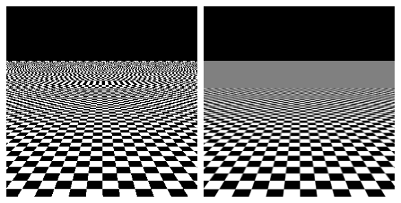
The glitchy look is aliasing. This is caused when you take high resolution textures and render them far away so they are higher density than the screen. This is normally solved with mip mapping, which is enabled by default on most textures, but I think maybe not for sprites, as they are normally used in 2D with sprites that can't get very small.
You can check if mip mapping is enabled on those textures and enable it if not.
Mip mapping generates lower resolution versions of a texture and automatically picks the best resolution depending on how far away it is from the camera.
Technically you're already using shaders with that ;p
But yeah that's actually a fine idea instead of making a shader specifically for drawing lines. Using unity's shaders you can just figure out the size and tiling needed and change those values inside of the material.
is there a way to random 2 colors for my grass?
it looks boring when the grass always has same color
Not using sprites and instead switching to Default with mip mapping enabled seems to have worked. I don't think I'll dive into shaders for now. I'll just use different textures for each tile. Thanks for the help!
did cubemap from refprobes change in unity 2022 compared to 2020?
instanced (property block Variable ) and gradient or random pixelate texture
Hey sort of confused with something here. I have a basic flow map shader set up here. I am giving the shader a texture that has 0.5, 0.5, 0.5 in all channels, and yet I am still seeing movement.

Any idea what's going on?
I am using the UVFlowMap node included in Unity's Shader Graph Feature Example package, so I'm assuming the implementation is correct?

Is this a float accuracy issue?
0.5 in all channels, I would expect a grey texture, but I see yellow ?
(or maybe you've imported it in RG format ?)
Also, double check that sRGB is disabled in the texture import settings 😄
Flowmaps only need RG don't they
If the texture is sampled as a normal map it probably should also be imported as a normal map
That graph doesn't seem to do the 0:1 to -1:1 remapping, so you might need to do it before
I assume sampling as type: normal should do that also?
(there shoud be a usage exemple to compare to)
Hum, yes, maybe.
Although a normal is supposed to be of unit vectors, so it "needs" a z value else you have a flow of constant speed in any direction.
IIRC Z is recalculated on the fly, so it might work.
So the texture that came with the Feature Example package was this.

and this is the demo shader

So yes, sampling as normal indeed is enough. Double check that sRGB is disabled on your texture import settings.
It is and I still get slight movements at areas where I set to 0.5. Even when I provide this texture to the sample material and up the strength to 50, it still moves.


Double check the pixel values ? Compression format ? else it might indeed be floating point imprecision 🤷♂️
Does the "true" implementation have floating point issues?
Is the Unity sample implementation here wrong?
I'm a bit unsure here, the implementation is pretty standard, it's all more about how the pixel value is remapped.
8Bit values map 0:255 to 0:1. So the "real" 0.5 is 255/2 = 127.5 ... But this doesn't exist 😅
oh god
which would actually produce a very slight movement
ya?
Yep, if your middle value is 128, it is slightly positive, so makes movement.
jesus christ it all goes back to the 1970s
You could easily "hack" away this by doing some filtering on the flow map value though.
wait how?
...is it subtract by 0.0039215686274509803921568627451
I can replicate the issue, 128 color values tug one way and 127 to the other
But how much is relative to strength and compression
At the default 2 strength it's not noticeable to me, even at low compression
Something like the following should nullify the imprecision
v = v * saturate( abs(v) * 128 )
Even for the effect I was going, I didn't notice it until a friend pointed it out.
Said there was a slight ghosting on a small element.
Had to zoom in to notice it.
And now I'm down the rabbit hole.
Sorry it's like 4am for me, why does this work?
saturate( abs(v) * 128 ) gives a 0:1 mask of the imprecision around the 0 value, and applying it to the flow value will force it to 0
This the right way to do it?
This one halves the flow amount for both 128 and 127 values, but doesn't eliminate it
subtracting 1/255 fully eliminates it

Halves .... hom, ok, maybe my maths don't properly math up :/
If subtracting 1/255 works, stick with it, but I think it assumes that the mid range value is 128/255, if for some reason you use 127/255 is might offset in the other way.
But 128/255 seems more correct to me.
I don't think just subtracting 1/255 works I just kinda blurted that out. What's gonna happen is that you're going to get either a -1/255 or a 1/255 value when it SHOULD have been 0. So any values in that range need to be clamped to 0.
Actually, is it even standardized how programs handle a 0.5? Will some round up when mapping it to the 255 range?
Wait... does this mean that Normal Maps also have this problem? That the default value is actually slightly tilted because we can't get true 0.5?
Yea, in a real world scenario you'd have values roughly around 128 in places where the flow intensity is meant to be generally the lowest so subtracting causes a bit of a jump between 128 and 127
Tbh usually flow maps don't need to be that precise because the whole thing will be flowing
I simply wanted an area with no flow >_>
Might want to lerp out the effect entirely in another step
I had a picture of a ship on some waves and wanted the waves to move and the ship not to move.
Or map the flowmap to a curve so it becomes proportionally less intense around mid/0, and more extreme at the ends of the color range
Do you guys have any good tools for making Flow Maps btw?
In this case imposing the ship on the waves separately would solve this issue, and also prevent the wave flow from sampling from the ship's pixels
another texture sample 😛
Or use an other channel on the flow map to mask out the ship, connected to the flow speed
holy big brain
Quite!
I'm okay with doing a small clamp on the flow map to gt rid of hyper small values though.
Jesus what a world.
The ship and other objects separate from the background could also be geometry, with vertex colors or an atlased flow map if you need to get funky with it
For a bit more context, this is actually a 2D image for a card back.
wait it would actually be values -1/512 an 1/512 right? Because it was the midpoint between 127 and 128, rounded to one of them, and then remaped to 0 to 1 when we're in shader land
So...
v = abs(v)
v = v * step(threshold, v)
I think?
Otherwise you do some branching stuff.
In pure code you'd be loosing the sign of V here, but yes, it's the logic.
Ah true so just
v = v * step(threshold, abs(v))
right?
hello, ive spent forever hours trying to fix this but i just can't get it to work. does anyone know what is up with my normals? please ping me. Using URP


Textures not imported as type: normal map I would expect
they are
They have tangent space normal map data in them?
i assume
Could show them
With the import settings
2d tree overlay shader, any tip for hide the trees behind the moutain ? (trees and the terrain currently are 2 object). The trees is just a plane

That was the issue I assume?
well, this texture isn't meant to have a normal texture, but i'd expect the triplanar map to work even if there's no normal
it would just be
a plain texture with no bumps
but the lighting issue persists
do you want me to show you the shader graph nodes¿
Is anyone able to tell me why the output of the highlighted node here

puts diagonal lines through my mesh? I'm trying to get a reaction from a point light to the normal map

The texture property needs to have mode: normal map so its default value is a neutral normal
how can i add a neutral normal? i didnt even know that existed
also this is happening
this material DOES have a normal map yet:
there is visible normal map stretching
weird jittery texture in those edgfes (i made sure there are no overlapping faces)
same angle shadow

Node settings of the texture property, though you wouldn't "add" it, just define what kind of default value to use when no texture is assigned to the property
Do i have to add a default texture, or change the mode...
i got the node settings here
Mode: normal map like I said
Default value can be none
actually I didn't set the texture to normal type in unity inspector 😓
I need some help with my 3D model, it doesnt appear to be culling properly, If i look at it from like a whole direction (lets say south) the model dissappears completely. I have to be looking at it from the North to be able to see it.


can you send a video? hard to tell from just images
Hmm first thought is that it has bad bounds making it be culled too much
The bounds of the skinned mesh renderer is probably incorrect.
snap!
Goddammit, for some reason the Bounds are in the Origin coordinates while my model is moved. But if i move the model it messes with the positions of various things in the heriarchy

ok what is going on, if i move my 3Dmodel anywhere the Bound won´t follow!
thanks
Yeah there is some kind of problems with the bounds
Alright solved it by checking the "Update when Offscreen"
hey, so i see that HDR colors aren't an option in sub shader graphs, is this the correct implementation ?

i see mixed discussion whether its the alpha channel is used as intensity multiplier, or if the raw vector values are just presented (like 5, 5, 5, 1). if i were to route in an HDR color into the "Emission color" input would this work the same as the standard emissive component?
it looks ok comparing side by side, but just doing a sanity check
any ideas where to start implementing this effect? What should I search for? I think it adds an outline to selected grid area? also what about the gradient going upwards


Shader has to be in transparent mode, then you’d need a position node to orient the effect to take place from bottom to top if it’s supposed to animate. From there gradient on the alpha channel
Hey folks, wondering how I can reduce the reflection on the floor? It's using a simple triplanar shader I created by following a youtube tutorial

Not sure if the reflection would be changed on the MAT or inside the shader itself?
What is it reflecting? Skybox? Light?
HDR colors go above 0-1 range, alpha is still alpha rather than exponent
I'm pretty sure
It's reflecting the spot light just above the statue
Is it a pbr shader?
Honestly, I'm not too sure, I just copied a simple 'triplanar' shader tutorial on youtube

Decreasing smoothness reduces specular reflections
I'd say more than reduced smoothness it needs a normal map, and optionally smoothness map for it to actually look good
But that's up to your taste
Would you be able to point me in the right direction to reduce the smoothness?
Do i just reduce the 0.5 value of smoothness?
Yes
That's got it, Thanks heaps dude
How would I sample a texture that's set by CommandBuffer.SetGlobalTexture()?
I cant for the life of me find how to access it in a shader after setting it
You may be moving the root bone vs the base transform for it all or something similar
I'm trying to keep edge line same size regardless object size, what am I doing wrong here?


My morning brain is unsure, but I think you need to multiply the edge width with the min(ddx, ddy), and use this to step the minimum of the gradients
Keywords literally create shader variants right? Does that shit scale exponentially? Like if I have 1 boolean keyword, that's 2. If I have 2 keywords, 4 variants? If I have 3 keywords, 8 variants etc etc.
For boolean keyword, yes, that's how it works.
For enum, the values are mutually exclusive, so for a 4 enum keyword, that's 4 variants, not 16 (2^4)
Makes sense. You still use the Enable/DisableKeyword method to toggle Enums, right? I found that you basically need to toggle all options at once to really get it to work. Like if you had A, B and C enum options and needed C, you would need to Disable A, Disable B and Enable C in code.
On a separate note, I have a basic shader that's just layers 3 textures on top of eachother, but I want to be able to apply lots of effects to layer 1 and 3. Holographic effects, parallax, motion, glow etc etc.
So I was thinking about how to best set this up from an optimization perspective (why do all this work in cases where some of the effects aren't needed?) and a clean inspector so all the fields don't become a mess.
Hello, I'm trying to create a HDRP lit layered shader graph with alpha mask being in one separate texture property each instead of one packed texture so I can tile and offset them individually.

I don't understand how I'm supposed to use the branch node if I add more layers
Plus it also seems like I need to create branches for each of my values (color, ao, normal...) which is a lot of branch? Or am I missing something?
Ok nevermind, I've added the branchings directly inside the sub graphs, so 5 different branching (I'm using alpha from main layer as global alpha so no need branching for this property). I think that should be the normal way to do that. If there's a better way to handle branching, let me know.
Keywords are good for really stripping code of the shader but create variants as you know.
But sometimes, for enabling or disabling a feature a constant float value is enough. Use dynamic branches in the code (if(f > 0)) to toggle the feature, and because the float value is constant on the material, only one branch is evaluated. But it doesn't result in multiple variants.
As for the clean inspector, either write a custom inspector, or use something like shadergraph markdown to have more UI options

GitHub
Markdown-like syntax for ShaderGraph properties, to make better material inspectors - needle-tools/shadergraph-markdown
I see two options here for branching the layer count :
- use a keyword enum which will create a nice 4 inputs 1 output node
- use a custom function with a switch statement, similarly to have 4 inputs 1 output
For the ease of connections, you could also pack the surface data in a single 4x4 matrix.
Let's say I'm sticking to shader graph. Does the same logic still apply with the Branch node? I thought branches were something avoid unless absolutely necessary.
Branches are bad when the different branches of a same condition need to be evaluated in a single wavefront (screen space pixels group, 16x16 or 32x32 iirc).
IE, when you use screen space noise to select between branch A and branch B. In that case the gpu group can properly optimize which branch to use for all pixels of the group, and needs to evaluate both for every pixel.
But is you use a constant value on the material for the branching, it knows that all pixels within a single group either use branch A or branch B, and can then only evaluate a single branch, without running the other one.
And yes, this also applies to shadergraph
The branches should be controlling if only 1 layer is used OR if layer 1 and 2 are combined (e.g. by a mix/lerp). This will repeat till you have all layers combined (e.g. 1+2 combo combined with layer 3 ect)
where are these patterns coming from? I get them when trying to use normal from height in shader graph (for a height/displacement map)

So the branching would be out of the sub graph with this solution ?
Yes
And if the enum is set to one layer, then the 3 other layers won't be processed at all, making it more efficient, is that correct?
Yes
My current sub graph is like this, the branching for each property is inside and I'm currently using a float for the number of layers. But this way, all layers are processed which is inefficient if I understood correctly?

The only way to make it efficient is to use a keyword then?
(I've been using the lit mask map as my default albedo since I only use greyscale, and I put my grayscale albedo inside the mask map blue channel, replacing the details map which I don't need
Hum, if I'm not wrong the branching logic should still work.
Subgraphs are compiled into separate functions, and when being evaluated all the layer functions are called, but those for "unused" layers won't do anything.
Looks like clipping. Do you have duplicate geometry?
Hm, but the unused layers would still be evaluated then, won't that affect performances compared to using branches with a enum keyword outside of the sub graph like you said ?
Are all layers still evaluated even with the keyword ?
The function will be called, but because of the comparison it will just reroute the previous layer inputs, without doing anything more.
It should be that much of a performance hit.
But indeed, if you want to be sure that the function is not called, the branching needs to be done outside of the subgraph
If you want to squeeze even more performances, you might be interested in this layer packing technique : https://unity.com/blog/engine-platform/experimenting-with-shader-graph-doing-more-with-less
(also, I find it suspicious that you are using overlay blend between the layers)

Unity
You can improve the runtime efficiency of your shader without sacrificing the quality of your graphics by packing physically based rendering (PBR) material information into a single texture map and layering it into a compact shader. Check out this experiment.
I'm trying to get a depth map from a screenshot that I take in game. How do I do this in Unity 6.1?
I haven't tested my shader yet actually, I was just assuming the default lit layered was already using overlay blend since it's the default option
Thanks for the link
Make a separate pass the renders the depth buffer to a render texture. Then save it to a file.
That was an interesting read. The dual color ramp method is actually a huge plus for grayscale albedo. I'm amazed by what people can think about to optimize stuff.
do you mean the custom pass? i think unity now uses the render graph exclusively?
Yes. I don't think the render graph replaces the render pipeline passes. It's a tool for managing them from what I understand. But yeah, you can probably add a pass via the render graph too.
hm. to be consistent I think i'd rather add the pass through the render graph. So I'm guessing I can trigger the render graph to apply the depth map shader and then save it? sorry if im asking too many questions
I assume so. I have very little understand of the render graph and generally render pipeline customization in the latest versions. You'll need to research it yourself.
I can tell you how that would work from the graphics API perspective:
- you bind the render texture render target to the pipeline
- bind whatever buffers and textures you need to the pipeline
- record a draw call with the specified shader that would draw the depth to the render target.
Done.
hm. ok thank you for your help. i will have to go more in depth
What is a “constant value” in this case?
Like if I expose a float in the inspector. Is that a constant? What if I do operations on it before throwing it into a branch node?
I don't have duplicate geometry, it's a tessellated mesh. This issue appeared when I tried to use normal from height for another heightmap as well.

Is anyone else experiencing the shadowCaster bug with unity 6?
the compiler for me just gets stuck on compiling the shadowCaster and prevents me from testing my game.
Yes, a float exposed in the inspector is constant.
As in, constant over the whole object in the current frame.
This here seems to be the place for culling issues. I believe my issue is simple but I still struggle with it. I'll have a video about it later (I'm short on time right now.) I'm actually working on a world for a game called VRChat but I think my issue is just basic / general enough. I'm tweaking Occlusion in my world and as you can see in my lil camera view, some things are not showing up. I did select very small object sizes, so those cubes should appear... even if they were too small, the big, darker box should definitely show up. I'm not entirely sure what's causing this issue. I can try smaller and smaller objects culling but it doesn't see to be the fix? Oddly enough, depending on where I'm looking, even if I'm right next to the button, sometimes they appear, sometimes they don't

is this what you meant

Yes
okay then it didn't work 😄
thanks though
sec
yeah its working, got another issue. thanks a lot!
hi!
is it possible to use tessellation in URP?
and is it valid to use URP in 2025 anyway for a pc game?
I hate shader graph so much I just want to write my shaders but it seems URP is really limited and HDRP more or less demands using the shader graph?
is it possible to use tessellation in URP?
Technically, yes, if you are willing to hand write your shaders
and is it valid to use URP in 2025 anyway for a pc game?
Yes, even more if you plan on releasing on more platforms, aim for more stylized graphics or higher framerates. But you don't have as many features provided out of the box as in HDRP.
I hate shader graph so much I just want to write my shaders but it seems URP is really limited and HDRP more or less demands using the shader graph?
Is it still possible to hand write shaders with URP and HDRP, but it is drastically more complex than in built-in because there is not equivalent to surface shaders.
can someone give me a monkey brain example of how to use Graphics.CopyTexture with a CubemapArray? the docs only go over how to use the SetPixels() method
What is the goal? CopyTexture is for copying in GPU memory, so it doesn't help for common goals like reading pixels in script or saving to disk.
I want to save reflection probe cubemaps to a CubemapArray so I can access them in any shader
basically sidestepping unity_SpecCube0 so I can sample multiple probes at once
It's definitely possible to copy one face at a time into the array, can't find confirmation whether you can copy a whole cubemap in one call.
my current code is along the lines of
CubemapArray reflectionProbeArray = new CubemapArray(2048,8,TextureFormat.RGBAHalf,true);

///...

    void SetupReflections(CullingResults cullingResults)
    {
        NativeArray<VisibleReflectionProbe> visibleProbes = cullingResults.visibleReflectionProbes;
        if(visibleProbes.Length>0)
        {
            for(int i=0; i<visibleProbes.Length; i++)
            {
                VisibleReflectionProbe probe = visibleProbes[i];
                Graphics.CopyTexture(probe.texture,0,reflectionProbeArray,i);
            }
        }
    }
All the cubemaps must be the same size and be a compatible texture format to work with CopyTexture.
I think you may also have to copy each mipmap individually.
rn im just prototyping so I dont necessarily need mipmaps
CopyTexture seems to throw some error about Graphics.CopyTexture called with null source texture
ok thank you
hey first time working with shaders so I don't know what I'm doing, I want foam where water intersects with objects, but isn't this supposed to be showing on the water surface, instead of on the object it's intersecting? 😅


Does anyone know if its possible to fix this distortion? Or at least make it so that the side without distortion faces the camera?


I can take closer sc for anybody who need them that shader graph is very hard to see
!code
Posting code
📃 Large Code Blocks
Use links to services like:
https://paste.mod.gg/, https://hastebin.skyra.pw/, https://paste.ofcode.org/, https://paste.myst.rs/, https://scriptbin.xyz/
📃 Inline Code
Surround code with three backquotes. Not quotation marks.
To format as C#, add cs to the first line:
```cs
// Your code here
```
Add a comment with a line number if there is an error message.
I'm trying to understand how renderer features work(URP). Here, I full screen pass renderer that's taking in a material named "temp" with a shader named "temp". This should make the whole screen white, but it's not and I'm not sure why. Here's my shader code although I doubt that's relevant:
https://paste.mod.gg/cxwfgmahmvtb/0


A tool for sharing your source code with the world!
When I create a new full screen pass feature, the default material inverts all the colors. I'm not sure what they're doing with that default material that I'm not doing here that makes their thing work.
A specific vertex shader is needed to correctly draw the fullscreen triangle. See https://www.cyanilux.com/faq/#fullscreen-shader
How do make my textures not pink?

Broken shader
I know its a broken shader, i need help fixing this
What render pipeline is the project using and what shaders on the broken materials?
A built in lit shader with urp for example will not work and be pink. Easy fix if this is the case.
I think its 3d core render pipeline
er probably built in renderer then. show shader on one of these materials here
Here is one

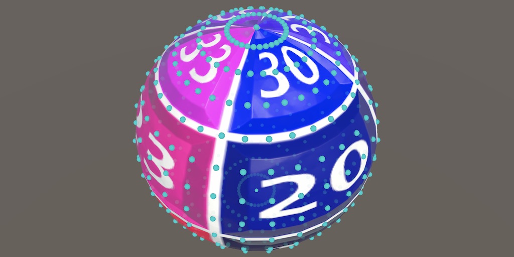
anybody know whats causing this? I'm just trying to find a way to seamlessly scroll a noise texture in the shader graph across the surface of a sphere but this is the closest I've been able to get
Well, do you understand how UVs are mapped on the sphere, specifically Unity's sphere if that's what you're using?
yeah
worth noting that I'm trying to avoid UVs by putting the world position into the UV input for the noise
because UVs will always have a seam
usually I just use like local/world uvs for spheres if I'm just doing noise to get around the wrapping issues with em
yeah thats what I tried but it produces that weird distortion around the x axis specifically
but if that's what you're doing then carry on, just can't make out from the graph there lol


Ah, yeah my shaders do still have somewhat a seam even with world UVs for the unity sphere, so there's probably a bit more to it
actually that gives me an idea, let me try a non-unity sphere and see if that works
better yet, I'll import a quadsphere so that the UVs can be even better
since I'm doing position I doubt it will change much but still
https://catlikecoding.com/unity/tutorials/procedural-meshes/uv-sphere/
Catlike has a way to use cubemaps which seems like an idea
A Unity C# Procedural Meshes tutorial about creating an UV sphere.
oh damn, I'll have to take the time to read through that later
bruh now it just stretches on the z axis

Quick question for anybody who knows about optimization tricks -
what is the performance difference for wrap mode? Clamped vs Repeat?
I was just recommended to do an operation inside of an HLSL shader as opposed to setting the texture to repeat, citing it is slightly more performant. I'd like to know why / how but google is not giving me the deep lore I'm looking for

Who were you recommended by to do that?
These settings just change the sampler parameters. And you need a sampler in order to sample anything from a texture.
These settings just define how the sampler is sampling the texture(or rather where).
I really doubt there is any noticable difference in performance between these settings.
You're probably looking at the wrong thing to optimize.
The "deep lore" would depend heavily on the used graphics API. If you're going with d3d11/12, you should be looking at it's documentation. But there's very little info in terms of performance. Performance is also very context dependent.
If you really want to optimize, you should use dedicated profiling tools, like PIX, Nvidia Nsight(or whatever tool is native for your target platform), maybe render doc.
Before deep diving into shader optimization, I'd use the unity profiler to see where the bottleneck is in the first place.
Maybe there's a way better candidate for optimization.
im not sure if this is the right place to ask this cause i dont even know how you would accomplish this but how would one go about making a texture or shader like the clothes in chowder or stans jacket from monkey island? that thing where it seems like the texture is just a global background that dosnt move when the object its on does. i want to use it on a shirt for a 3d charicter model im making but i have no idea how to gow about it, these are decent examples of what im trying to accomplish https://youtu.be/htGt6frPSH0?t=76
https://youtu.be/STnYDchAn78

Chowder learns that messing with Truffles' game night means certain doom. But he's willing to risk it all for a taste of the Mevilled Eggs she's serving.
Welcome to Cartoon Cartoons!
Dive into a world of nostalgia with Cartoon Cartoons, your ultimate destination for classic cartoons. Relive the golden era of animation with timeless favorites l...

From the series Stan makes a return as a lawyer. Gotta love Telltale.
World UVs
Er actually it's a screen position shader
Yeah, screen space UVs
ah yea thatl work, i think i found some decent tutorials for those. hopefully this goes well, thanks
in house tech artist that used to work at unity.
I believe him but didnt have time to ask him to go in depth
it's also not an optimization stage. I hit a point where it was "2 options how to fix this development problem: Do an extra step in the shader or modify all our texture import settings" and he said do it in the shader. I'm just curious if there's a well known reason why, and it sounds like not 🤷
Hello, using hdrp shader graph, which blend node or similar node do I need to use to stack a texture on top of another, the black color being ignored and the whiter the top layer is, the more it replace the bottom layer texture.
Overlay and screen don't see to do that
A side effect of doing it in the shader is that you also need the manually compute the derivatives and sample with SampleGrad for proper mip level filtering.
"Overwrite" blend mode, or just the "Lerp" node.
Thanks! I thought it would also overwrite the black pixels
I've got a weird bug in my shader graph. The default value field does not appear at all. It's supposed to be a float. Is it fixable?

Even restarting Unity doesn't fix the bug
You might have ticked the "Use Custom Binding" option under the property/input in the subgraph
(allows you to set a custom name rather than the regular input field - you'd usually use it with the Branch On Input Connection node)
That was it, I clicked by mistake, I didn't even know what it was used for lol. Thanks !
How can I use sprite Unlit shader on Overlay UI?
Its coming black.


on Screen Space - Camera its working fine but not working on "Overlay".
There's a "Canvas" graph type in 2023.2+ and Unity6. Older versions didn't have proper UI support
I made a triplanar shader for my hdrp project. I found how to add a normal map but I can't find how to add a height map. Are height maps supported by shaders? That's what I have so far

The heigh map is either used for :
- Parallax mapping through the parallax node or parallax occlusion node. But it doesn't work well with triplanar and you might have to do your own implementation
- Vertex displacement with tesselation, in that case you need to enable tesselation on the shadergraph setting and make the displacement yourself in the vertex stage (position + normal * height)
so it would be better if I used vertex displacement right?
Probably easier to setup.
I put the position + normal * height here?

also when you say normal * height normal map * height map or normal map * the depth I want?
vertex normal * heightmap value * amplitude multiplier
is that a node that I need to activate somewhere
"Normal Vector" node

Why do you want to multiply the normal vector by the "normal from texture" ?
It wasn't letting me put the texture in directly
Sample the height map with the "Sample Texture 2D LOD" node (as the regular sample texture 2D doesn't work in the vertex stage).
so like this do I set it as normal or like this. Also is the position good

Normal and Position nodes should be in "Object" mode, else it seems good.
Ah stop, no, I always forget that for tesselation it is a displacement that is connected, not the final position.
So remove the "add position"
wdym just attach the multiply immediately?
Yes
did I select the wrong things?

Thanks for the information. Is there any other way to use shader graph on Canvas?
I don't think so.
I don't know what your displacement texture and tesselations settings look like, but what is here is a possible outcome.

"Tessellation Mode" = "None" ? 🙂
Well, should still be ok, the phong tesselation is for smoothing geometry
should I send a pic of all the shader graph
I might have messed somethng up
It's texture on top, normal in the middle and heigh map on the bottom

Normal Vector node should use "Object" space.
What does the height map look like ?
and the textuer on too?
wait I had the wrong height map selected let me send a pic
it fixed with the normal thing
"Tessellation Factor" is the amount of times the geometry is subdivided to have smaller vertex deformation.
1 means that fron the 1 quad face you end with 4. Wich is probably not enough for the texture that I can see.
this was the correct height map

let me increase it also how can I add a custom depth too
What do you mean by "custom depth" ?
Expose a float parameter on the shader and multiply it with the normal*depth
so after the first multiply I add the float I had
not add, multiply
sorry multipy I meant
heihtmap value * float height * normal
It doesn't seem to be having an effect
shoudl I try increase the tesselation factor right now I put it as 4
Maybe even more, your are starting from a very low polycount
what's a good average number to start the testing>
I can't give a magic number here, it can depend of many things.
- the "minimum triangle size" limits the amout of tesselation for a single triangle isn't smaller than X pixels on screen.
so I just put a bunch of random numbers if it gets better I stick close to those numbers
and are there any big downsides to having a big number
It will increase rendering cost.
its looking like this?

Interesting, it looks inverted. But it's definitively doing something and I can distinguish the heightmap shape here.
That's me trying to offset it inwards cause the normal height map that's what it was doing but this one feels off when I go the other way round it offsets the planks in a detached style and in the wrong places

I'm trying to mimic the block next to it
so I can have an easily tileable version of it
The "detached style" is expected because the cube mesh has "hard edges" : eight cube face ha a normal pointing in a different direction, so it is "pushing" the displacement along it, resulting in the holes at the edges where each face is pushed in a different direction.
yeah that makes sense. That's why I was trying to give a -depth
but at the same time it shouldn't be leaving the height map at that point
could it be I need to also apply the triplanar to it?
Also, the displacement is not matching the color/normal maps because the displacement texture is sampled using the UV, when the other ones are using triplanar.
Sadly, you can use the triplanar node in the vertex stage and would have to recreate the triplanar logic with multiple "Sample Texture 2D LOD" nodes for it to match.
Triplanar vector 4 output is the RGBA color of the input texture. In the case of a height map you could just limit to the R value by using a vector split node, or swizzle.
so I create a triplanar from just one value the red as its black and having all the colours and stuff and I attach that to the multiplies?
In theory, yes. But I don't think it will allow you to do that ?
could we multiply the world position with everything?
Yes but ... why ?
since the swizzle things doesn't work to try to shift the height map according to the world position
Chances that it matches the other triplanar sampled textures are low
ye
so splitting it didn't work what else could I try
recreating the triplanar how you said with the texture 2d lod stuff?
do you know how I could do that or should I try looking it up
You can probably find good sources by searching a bit yourself, or look at the shadergraph feature examples which contains triplanar projection subgraphs.
I'll continue looking into it tmrw
From what I'm feeling I think I'll need to make 3 uv maps for the z y and z of the texture and then map it out to thst location
How do I change the value of an enum keyword at runtime? Do I need to use DisableKeywords on all values of the enum and EnableKeywords on the value I want or do I use SetKeyword?
This expains how they work: https://docs.unity3d.com/Packages/com.unity.shadergraph@17.3/manual/Keywords.html#enum-keywords
Thanks!
How do I properly colorize my greyscale texture ? When I use a simple multiply, black color will show details but when I use white, details disappear and some barely opaque pixel becomes more visible.


What does your greyscale texture look like ?
The usual manner to "tint" an albedo texture is indeed to multiply with a constant color.
This one. But I packed it into the blue channel and I load this packed channel from the streamingassets.

And I'm using UnityWebRequestTexture to load it.
yield return uwr.SendWebRequest();
Texture2D tex = DownloadHandlerTexture.GetContent(uwr);```But I remember there was a linear option when creating a texture. It seems like this method of loading can't change it to linear so maybe it's the gamma affecting the result?
it probably presumes the image is srgb (which is usually the case for most imported textures too)
Do you guys know any black magic fuckery to make particles meant for unlit shaders to work with lit shaders?
I tried several sample lit shaders and they all render my particles as solid blocks
maybe it's a transparency issue, I don't know. What should I even look into?
"Meant for unlit" in what sense?`
VFX graph should support lit and unlit natively
In HDRP lit shaders for Particle System are included in the importable sample
What I mean is, I bought a particle asset and its prefab uses the standard unlit particle shader
When I use any of the HDRP lit shaders, the particles break and instead display as solid of block of (correct) color
the particles use flipbooks. There is a flipbook lit shader as well but it behaves the same way
I'd assume it's something related to transparency + lighting, but I don't know what do look for
PS or VFX Graph?
shuriken
I'am new to Unity and i have just found out about shaders this monday. I have found and tried with 5 tutorials but i still can't configure 2D shaders in Unity 6.1 are there any tutorials about how to do it?
Ok I fixed my issue. When I changed the material's shader to one of the lit ones, the albedo map got cleared. Just needed to assign it
now it works but looks kinda cursed, I will attempt to fix that with settings
Fixed some of the issues. Seems like the default hdrp particle lit shader has smoothness set to 1 for some goddamn reason and it's not an exposed property
can't imagine why
Those shadrrgraph stuff I add the addon and look at a triplanar shader graph or is that just the different nodes available in the shader graph menu
Et imports as assets in your project and you can inspect them, the shadergraph as well a the newly added nodes as subgraphs.
And then i take the subgraph for the triplanar copy it and make a new one with the texture 2d lod instead of what it uses
Hello, when I change my enum keyword at runtime, the material does update but not the value in the inspector

I use this to change the keyword at runtimemat.EnableKeyword("ENUM_VALUE");
Is there something I'm missing?
If you also want the inspector value to change, you need to use mat.SetFloat with the property reference name and value index.
Oh ok, thanks a lot
Do I need to use both EnableKeyword and SetFloat then ? Or just SetFloat is enough to enable the right keyword ?
Both.
The float is only for material editor display, while the keyword is the actual shader code change.
At runtime, you only need the keyword though.
When you are looking at the material inspector, what is happening is that when you change the value in editor, the float field changes, and then the inspector UI reflects this change to the keywords.
Ok thanks
My custom shader trying to replicate the HDRP Lit with the difference being the albedo is grayscale and packed directly in the blue channel of the mask map (I don't use the detail mask) but it seems to be struggling with the mipmap. First image is the HDRP Lit and the second one is my shader graph. The cloth gets blurry when it gets far away from the camera which should be a mipmap problem. The HDRP Lit doesn't have this issue. Is there any solution to have better mipmap with a packed texture?


If mipmapping doesn't work you're using the wrong texture sampler
SampleLevel is the function with mipmapping
https://learn.microsoft.com/en-us/windows/win32/direct3dhlsl/dx-graphics-hlsl-to-samplelevel
But there's only one sampler in my customer shader for the mask map. How can it be wrong?
Is this one of those shader graph things?
Yes

I'm using the same channels as the HDRP Lit mask map. So red is metallic, green is ao and alpha is smoothness
The only difference is the blue channel. For Lit, it's used for the detail mask but for my, I use it for greyscale albedo which I multiply by the color then plug to the color of the graph
Color, smoothness and AO seem to be working fine as you can see from the images
But it gets blurry when the texture gets further away, I think that's related to the mipmaps
But there's not option for mipmap in the shader graph so I'm not sure howto fix that
It should be the same as the lit
Yeah checks out. That sampler function calls SAMPLE_TEXTURE_2D, which takes the mipmap level into account.
Actually not entirely sure if this is correct 
That's just the global mip bias.
Hm, not sure I understand your reply but is there any fix for this difference ?
The lit shader should also use the sampler function shouldn't it?
Just thinking it through
There should be a mip sampling mode in the inspector, for the Sample Texture 2D node

Should be set to "Standard"
Yes it's set to standard by default

Does your texture use anisotropic filtering? It looks more like that than a mip issue tbh.
This is my mask map texture

But both the lit and my shader graph use the same texture
And lit also use the greyscale albedo in a separate image
Which I packed into the blue channel of the mask map for my shader. It should be ignored by the lit since I don't use a detail map
Alpha is set to "none"
Yes, this is a packed texture. it has no alpha
Can you set the aniso level to the maximum value?
Ok
Hm, no luck, same result. Texture gets blurry only on my shader when far away from camera
I've tried another simpler shader graph with my mask texture and this blurry bug doesn't occur so there must be some node issue in my complex shader. I'll look into it
OK I found a solution. Changing the sampler texture mipmap to bias and setting it to -1 fixes the issue. Almost the same result as the lit hdrp. FInally/
That just turns mipmapping off
mip maps + tri linear filtering should be making something look blurry at a distance, thats the whole point
ofc not crazy blurry but enough to look natural vs shimmer
Ah, that explain the result lol.
Ok, I didn't know, thanks
decent article to explain a bit more: https://medium.com/@rgbguy/mipmaps-and-why-they-are-useful-6d3e33c68b16
Medium
MIP is short form of latin phrase “Multum in Parvo” which means many things in a small place.
Could someone hive me helping hand?
That's very wrong.
The regular Sample operation (and "Sample Texture 2D" node) also uses mipmaps, but it determines the one that is required from the derivatives of the input UVs.
Yeah I found it afterwards after sorting through macros for a bit
It's mapped to SampleBias
what's the equivalent to godot's MODEL_NORMAL_MATRIX in unity?
It's described in Godot's documentation as
Model/local space to world space transform for normals. This is the same as MODEL_MATRIX by default unless the object is scaled non-uniformly, in which case this is set to transpose(inverse(mat3(MODEL_MATRIX))).
for context I'm trying to translate this from godot's glsl to urp hlsl
vec3 vec_dir_wd = MODEL_NORMAL_MATRIX * vec3(vec_dir_tg.x, 0.0, vec_dir_tg.y);
https://docs.unity3d.com/Manual/SL-UnityShaderVariables.html many matricies are exposed to shaders
Though ObjectToClipPos() will be introduced automatically I think when using that one in a shader 🤔 (i forget)
yes but I don't know which one I should be using
Oh I dont actually know if there is easy conversion to/from tangent space
Sounds like it might be unity_ObjectToWorld (if scaled uniformly) or transpose(unity_WorldToObject)
So should also be equivalent to TransformObjectToWorldNormal(v) function (from SpaceTransforms.hlsl in srp core shaderlibrary)
this might be not shader specific but I'll ask this here anyway
I have a mesh with two materials, I want to overlay another material (parryIndicator) over those material by adding the overlay material into the mesh renderer
But somehow it only overlaid on the last material (the straw cape/Mino), is there a way to make it overlaid on the whole mesh instead?


So the problem here is you've a mesh and a submesh, and you want the last material (which is an overlay) to apply to both but it's only being applied to the previous submesh? I think I may have had this problem before but I don't think using the editor will work here to specify that
I usually just do another mesh rendering if I want to do some overlay
Ah right, I forgot that its treated as submesh, and the additional shader only applies to the last submesh 🤦♂️
Seems like the "fix" is to not having submesh? either join everything as a single mesh or make it as another mesh?
Probably yeah
Cool thanks
what's the difference between the pink and blue node connectors
I'm trying to first make a normal shader with a height map and then going to triplanar. But the heigh map looks a bit choppy and not smooth. What can I change to fix it?


Are texture 2d arrays always more performant than sample texture 2d if you're blending different textures on the same material via vertex color?
Yes that way you only have one texture loaded in the gpu memory instead of two separate textures loaded. Both ways are still two samples
Yea but what do you mean by both are still two samples? You mean to say that just literally?
Cause even if you have like 16 textures, it's gonna perform fine vs a splat map or even vs vertex colors with less textures, as I understand it
i followed along a tutorial, but is there anyway to make this toon shading colored? i think shadows being grey tends to look kinda ugly (second pic is whats inside the node group highlighted)


i keep trying to do something like this, but it changes the body instead of the shadow

If you want to tint the whole thing, add the ambient to the Smoothstep output, then Multiply by the Color. Or replace the Ambient Strength with an Ambient Color.
If you want exact control over the colours of the "shadowed"/lit sides, put the Smoothstep output into a Lerp node with A & B set to Color nodes.
what am i not understanding about Sorting Priority? I have 2 gameobjects, the first has a sorting priority of 0 and the second has a sorting priority of 50. To my understanding, the second object should always render after the first, but it still gets blocked for some reason. is there anything that im missing?

hey i made this toon shader and im trying to add normalmap support to it. can somebody explain why i cant drag it into the normal output?

idk if its important but its in urp and unity 6000.0.41f1
Afaik Sorting Priority is an offset to the Render Queue behind the scenes, which is determined by other settings. (Opaque has a queue of 2000, Opaque & Alpha Clipping is 2450, and Transparent is 3000). The priority would only affect the order objects render in if both materials have the same Surface Type & Alpha Clipping.
If both are opaque, the sorting priority still wouldn't force the second object to render over the second though - as opaque objects write to (and test against) the depth buffer. You'd instead need to override the ztesting mode using the RenderObjects feature or a custom shader. (Probably using ZTest Always, but then faces in the mesh also won't know what order to render in unless you do 2 passes like this discussions post)
shader I made completely in shader graph, anything I should add lighting-wise?


The normal map would need to override the Normal Vector node probably used inside the CalculateLights subgraph. Can add an input to the subgraph to handle that. (Good place to use a Branch On Input Connection too, but optional)
The normal sample also doesn't look correct. If it's a blue/purple-ish texture Tangent space and a Transform node to convert from Tangent to World for the lighting calculations. Also no need for the Normal Unpack node - the Normal mode on the sample handles that
i tried it like this now but i prolly did something wrong as it still doesnt look correct on the material

Use Absolute World space on the Transform node instead of Object
Make sure you assign a valid normal map to the property & connect in main graph
this is what my normalmap looks like and what my object looks like with my shader (top) and the default lit (bottom) i see progress but its still not working right


also the colors i set are different but i think thats not the problem
Im using unity 6 urp, custom shaders are working fine in play mode but in build they are pink.
no shader errors at all and i've tried disabling all the stripping options for shader varients
I've also created a new shader variant collection and added it to this list of preloaded shaders and added the specific shader to the 'always include shader' section in graphics settings
im sorta losing my mind here what haven't i tried yet
Make sure you're using the same quality settings in the target platform build. Or make sure that the correct settings use the same render pipeline.
Yeah that all seems in check
i've tried it in new unity projects as well and builds are still breaking
i've also tried using different unity versions
Did you try looking at the player logs?
Or attaching a frame debugger to the build.
I looked at the player logs
didn't see much but i'm not familiar with the specific logs its putting out
chatgpt says its fine but 🤷♂️
Anything about shaders?
haven't tried frame debugging
nothing unusual as far as i could tell
Try the frame debugger then. It might reveal more details.
will do
Check the build logs to see what shaders are included (it should mention variants and the reductions from stripping)
If ones you need end up at 0 then it could be the cause.
addressables had a bug a while ago that would cause 100% stripping for shaders used
what am i looking for exactly?
I'm now getting an issue with the standard urp/Lit shader but that seems unrelated?
there should be a stage where it lists all shaders and it processes the variants and reduces the variants built
ok i don't see the custom shaders being included
you should enable keeping the urp debugging shaders and then enable urp debugging in a build: https://docs.unity3d.com/Packages/com.unity.render-pipelines.universal@15.0/manual/features/rendering-debugger.html
Look for things like this:
    Full variant space:         301989888
    After settings filtering:   24576
    After built-in stripping:   48
    After scriptable stripping: 16
    Processed in 0.00 seconds
    starting compilation...
    finished in 0.62 seconds. Local cache hits 0 (0.00s CPU time), remote cache hits 0 (0.00s CPU time), compiled 16 variants (4.34s CPU time), skipped 0 variants
Prepared data for serialisation in 0.00s```here it only keeps 16 variants. If it goes to 0 but you know its used then thats a bad sign
I'm not getting those debugs, maybe i need to enable something?
I see a lot of
Uploaded shader variant to the GPU driver: Hidden/Universal Render Pipeline/LutBuilderLdr (instance 0x128), pass: LutBuilderLdr, stage: vertex, keywords <no keywords>, time: 0.077 ms
Uploaded shader variant to the GPU driver: Hidden/Universal Render Pipeline/LutBuilderLdr (instance 0x128), pass: LutBuilderLdr, stage: pixel, keywords <no keywords>, time: 0.089 ms
Looking into frame debugging now
its in the editor log/std output when building
oh im in the wrong place
you want to basically check what happened with shader compilation for your builds
yeah im in player logs
yes ok it is getting stripped
Compiling shader "Custom/Portal" pass "Unlit" (vp)
    Full variant space:         1
    After settings filtering:   1
    After built-in stripping:   1
    After scriptable stripping: 0
    Processed in 0.00 seconds
    Prepared data for serialisation in 0.00s
how do I exclude it?
it must think no variant is used so its fully stripped
can i whitelist it somewhere?
is the shader used by a material that is in the build?
Resources?
doesnt workj
I could try turning off all stripping but that took like an hour to build last time
yea not a solution as builds will take a stupid amount of time. Is it shader graph or .shader file?
.shader
oh god well
ive changed absolutely nothing and now it works
thanks for your help
i might be back if it decides to stop working
What type of shader do I need to use if I want a procedural material for a UI image?
It doesn't seem to work using the same one as the sprites
At least not transparency??
Ok, wtf, why does it show tranparency alright on the scene window but in game decides not to

Can be something in the camera?
If you're using shader graphs, you need to use the Canvas Graph type in 2023.3 / Unity 6. Older versions didn't have proper UI support - though it would somewhat work if using a Screenspace-Camera canvas (not Screenspace-Overlay)
how can i rotate a float4x4 matrix around a vector by x degrees?
Hi, is there a way for a material with emission to be affected by lighting? like if theres a light it can have shadow and if its dim the color will slightly darken? i really like the color of the mat with the emission and hdr
I'm not sure what you mean by rotating a matrix but I assume you just mean multiplying it by the rotation matrix which would be https://en.wikipedia.org/wiki/Rotation_matrix#Rotation_matrix_from_axis_and_angle
If you can do it on C# side, the matrix would be something along the lines of Matrix4x4.Rotate(Quaternion.AngleAxis(...
unfortunately even though I know its more expensive my needs kinda require it to be done on GPU
Alright. I'm just wondering whether there is an easier and less boiler plaity way to do it in shader code (using some built in functions) which there likely is but it also depends on the shader language
I have been trying to recreate this shader for the last hour or so but im fail to recreate the adding color with step:https://www.youtube.com/shorts/nKztilUwAG4. If someone could assist me i would be really gratefull the image shows my current progress.

It's probably because your are using step after multiplying with the WaveStrengh :
You are stepping an already scaled value, if you use the output of the Sine node instead, you know that the step input value is in the [-1;1] range.
Ohhh makes sense i will try it out later and will give feedback if it worked out. But ty ❤️
I'm working on a custom terrain shader - trying to hide holes at a certain distance and for some reason that if test is doing nothing:
#ifdef _ALPHATEST_ON
if(posInput.positionWS.z < 10)
{
        float hole = SAMPLE_TEXTURE2D(_TerrainHolesTexture, sampler_TerrainHolesTexture, input.texCoord0.xy).r;
        GENERIC_ALPHA_TEST(hole, 0.5);
}
#endif
This is a custom pass that takes a PositionInputs struct.
I tried to debug using:
terrainLitSurfaceData.albedo.r = posInput.positionWS.z / 300;
And I'm seeing expected results there - fading to red approximately 300 meters from the camera.
Alternatively, going branchless, still nothing:
float hole = SAMPLE_TEXTURE2D(_TerrainHolesTexture, sampler_TerrainHolesTexture, input.texCoord0.xy).r;
hole = lerp(hole, 1.0f, posInput.positionWS.z);
GENERIC_ALPHA_TEST(hole, 0.5);
posInput.positionWS.z behaves like it's returning 0. Unless I plug it into the albedo, where it returns the expected value. In the same function.
IIRC, terrain holes are "real" holes (no triangles), not alpha test
No, it works fine if I set hole to 1 manually
Oh, ok, my bad.
At first I'd say to instead use length(posInput.positionWS) instead (else you are purely testing on the z positive value), but it's still strange that it behaves differently when plugged in albedo 🤔
From what I can tell the clipping happens during the depth pass, while albedo is done during the Gbuffer pass
This does raise the question why they run this entire expensive pixel shader for the depth pass
Solved using input.positionSS.w, which is filled during the depth pass.
I am making a Chromatic Aberration subgraph. I am creating it by sampling the same texture 3 times at slightly different UV offsets, and then combining the R, G and B from the different textures samples. How do I combine the alpha? Here is the current graph.

isnt it usually used in post process where alpha doesnt matter?
If you really need alpha, you could take the average, or maybe use the RGB to luminance weight for accumulating it 🤷♂️
Add them all together, then divide by 3?
😛
Yes
Or something using these constants :
alpha = 0.2126 * RAlpha + 0.7152 * GAlpha + 0.0722 * BAlpha
But like rakiat mentioned, usually chroma aberation is a post process where you don't care about alpha.
I tried using real time raytracing in my HDRP project and my shaders stopped compilling and I got error message Shader error in 'Shader Graphs/BarkShaderMoss': Opcode DerivCoarseY not valid in shader model lib_6_3(closesthit).. I have disabled the raytracing but this error remains, any idea on potentiall fix?
Trying to create a color replace shader (so I can recolor outfits of players for example).... but this doesn't seem to work.
Tried following a simple tutorial but am I doing something wrong? Cause it works in the tutorial
https://www.youtube.com/watch?v=XW2qW1sDj_A


ok so I seemed to fix it when I changed the Range to "0.1" but why is this the case?
The error is because somewhere in your graph derivatives functions (DDX, DDY) are used.
As for the remaining error, sometimes there errors still display in the import inspector or console for no reason, did you try to reimport the shadergraph asset ?
yes. I kinda figured out what happened. I turned out that it wasn't every shader that was giving me this error but rather a signle shader that was giving me 8 similar errors. So I removed that one and the rest works
The range value is the error threshold for the color matching. When it was set to 0 it required the exact same color between the texture and the "color to replace" value to work, so I suspect that it was not a perfect match before, maybe due to compression or float approximation.
Re-generating the HLSL from the shader graph should work
Should also make ray tracing work
Will try that, thanks
one more thing.... since this is going to be a multiplayer game, I need a way to make this work for other players. Atm if I just do this all players would have the same material values and look the same... so what should I do I guess?

a friend of mine said something about "material variants" or something? But doesn't know a specific term for this so its hard for me to google or lookup what exactly I need to do
From script you can change the colors using Material.SetColor .
And by accessing the material from the mesh with MeshRenderer.material a copy will automatically be made to avoid modifying the original material asset.
At the end you will have X players with X different materials and colors using the same shader.
so something like Material.SetColor.SwitchToThisColor2 = Red/ColorPlayerSets; or something?
You might want to look at the scripting API (or playmaker since I see you're using it).
The correct syntax for example is : material.SetColor("ColorReferenceName", Color.red);
tried coding it but haven't really been successful so far. Any idea on what im doing wrong here?
using UnityEngine;

public class ColorChanger : MonoBehaviour
{
    [SerializeField] Color color1;
    [SerializeField] Color color2;
    [SerializeField] Color color3;
    [SerializeField] Color color4;

    // Start is called once before the first execution of Update after the MonoBehaviour is created
    void Start()
    {
        SetColour();
    }

    private void SetColour()
    {
        foreach (MeshRenderer renderer in GetComponentsInChildren<MeshRenderer>())
        {

            foreach (Material material in renderer.materials)
            {
                material.SetColor("_SwitchToThisColor1", color1);
                material.SetColor("_SwitchToThisColor2", color2);
                material.SetColor("_SwitchToThisColor3", color3);
                material.SetColor("_SwitchToThisColor4", color4);
            }
        }
    }
}
cause here... I am trying to make it so I put it on a parent of the character body, then apply the color changes to everything that is a childed object of that parent
https://docs.unity3d.com/6000.1/Documentation/ScriptReference/Renderer-materials.html :
Note that like all arrays returned by Unity, this returns a copy of materials array. If you want to change some materials in it, get the value, change an entry and set materials back.
foreach (MeshRenderer renderer in GetComponentsInChildren<MeshRenderer>())
{
    var mats = renderer.materials;
    foreach (Material material in mats)
    {
        material.SetColor("_SwitchToThisColor1", color1);
        material.SetColor("_SwitchToThisColor2", color2);
        material.SetColor("_SwitchToThisColor3", color3);
        material.SetColor("_SwitchToThisColor4", color4);
    }
    renderer.materials = mats;
}
still not working, am I just not connecting to the renderer still I guess?
Because I if I edit the Material variables from the Shader Graph directly it works... so its a connection issue to the renderer right?
From what I see, it should work 🤔
Any errors in the console ? Did you try loging things (like renderer names) to check that it passes on the proper objects ?
no errors, but I can try logging
I was using MeshRenderer in script.... but my character used SkinnedMeshRenderer 😐
Makes sense.
Hi there, I retrieved an asset using Command Buffer in URP, those call don't batch with the SRP batcher, I'm trying to squeez every last drop for mobile and I was wondering if there were an extensive guide somewhere to help me port the Render Feature to use the BatchRenderGroup API ?
but ty for helping me.... I finally got that figured out and I think I can probably figure out how to replace meshes with the skinned mesh renderer
The documentation seems nice but as I don't know the Command Buffer API neither I'm a bit at a loss, or better, I'd like to know if I can 1:1 the thing or if Command Buffer and BatchRenderGroup are totally unrelated ?
CommandBuffer is for executing many different commands on the GPU. BatchRendererGroup is an API solely for generating draw commands. In what way is your asset using CommandBuffer?
CommandBuffer is for executing many
Hello, I am looking for guidance or resources on how to add height map functionality or displacement to the unity toon shader. Its based on DX11 tess but its Tess CG file is missing any references to height.
is there any reason transparency wouldnt be working with urp? trying to convert my shaders to urp but it just totally disregards my transparent pass
left: built-in
right: urp


didn't even touch the shader code and it already doesnt work
By that you mean you're using the shader code from birp version, or using urp defaults?
Is it a custom transparency pass?
There is a basic displacement tessellation shader example in the doc.
anybody know if there's a (preferably simple) way to make an arbitrary amount of semi-transparent sprites, positioned, say, like this, have the same brightness throughout instead of blending with eachother

Stencils would be one solution:
https://docs.unity3d.com/6000.0/Documentation/Manual/SL-Stencil.html
That way one is discarded if they overlap

i see
Out of curiosity, do you know how that could be done in the HDRP? What pass should a tessellation program run in?
A lot of them.
Basically, take a generated shader from shadergraph with tessellation, and look at all the passes that declare a tessellation stage.
You'll need it for gbuffer, depth, shadow, forward ....
Right, so all of them except probably ray tracing
I suppose shadow could live without too
Really depends on what your are doing with the tessellation, else the difference between the shadowmap and view geometry could easilly lead to shadow artifacts
Yeah will have to experiment there
I am doing SDF lighting/shadows/ao using primitive SDFs. I am coming across these artifacts sometimes, what are they? like, what should i search for to try and figure it out

It's quite hard to understand what is the artifact here. But since it looks like it's some "steps", could it be that you need to increase the number of raymarched steps to increase precision ?
this was my first thought, though changing the number of steps and minmax distances doesn't seem to alter it
how can I make my outline shader thicker? to match my character's artstyle

this is my current setup atm

when i try increasing thickness it just renders incorrectely because its not filling the space between the object and the outline (and me trying to explain the issue just rubberducked it lmao)

Hey Guys! Welcome back to another CG Smoothie Video! In this video I'm bringing you guys a new Unity Game engine tutorial! This time, we're learning how to use the unity game engine to make 3d outlines around characters and objects in your game using the Unity Shader Graph! I think this is one of the BEST Outline tutorials out there! If you guys...
thats the exact guide I used
but again, for him it looks good, not for me
sorry didn't mean it as a lmgtfy
all good
but it is the BEST so you should be good 😛
im on urp if that helps
the closest I found that matched my hb's artstyle was maybe cell shading, but I don't want cell shading because its a cartoon-like game, not an anime
i'd assume the proper proper way would have something to do with stencil buffer etc but i dunno
Reddit
Explore this post and more from the opengl community
this tutorial is for smooth shaded objects only damn
my objects are definitely not smooth shaded, its low poly
isn't it just a screenspace outline effect applied over whatever?
no sure that shading would have any impact
that the outline is its own shader
oh no, its a shader graph
The shader has an Outline Thickness property
That's not doing what it's supposed to?
well yes but when I increase the thickness, it just floats in the air and the space between the object and the outline is transparent
let me show a pic
thickness: 0.01235

thickness = .1

you can see it better on the couch down there
and also its not adding an outline to every part regardless of direction, I believe that has to do with normals?
In couch's case I believe the outline is going inside the wall because it's above the couch's surface but the couch is right up against the wall
And floor for the radiatior
i forgot why it was on back and not both

the sofa is clipping a bit through the wall but its not an issue
It's an issue for the outline
it wasnt clipping through the wall, so idk then

it should just be black between the outline and the actual object

It has to be far enough away so the outline's added width is not touching the wall
Move the sofa up and away from the surfaces until the outline appears
Anyway those are fundamental limitations of this particular outline method
You can tweak the properties and the object positions to make it look potentially adequate from the camera's perspective
If the player can't move the camera right up where the errors appear, the errors won't matter
Otherwise you'll have to find a different method
Each has drawbacks
https://ameye.dev/notes/rendering-outlines/

🖍️ Explaining multiple techniques for rendering outlines and highlights for real-time applications. This includes vertex object-space as well as screen-space methods. This can be used to render outlines in Unity or Unreal. Outlines can be used for gameplay reasons or aesthetics.
is there anyway to avoid that? because I really have some space constraints world wise
The normal offset method is similar, but it fixes the outline becoming proportonally detached
But it has the same clipping issues and additionally it'd have a splitting issue with any flat shaded geometry edges
i dont want anything floating around
Currently your outline is created by duplicating the mesh and expanding the duplicate
You can shrink the mesh by the same amount so the space doesn't change
If the outline is resting on the floor against the wall without clipping, it won't really be "floating"
Only the object inside the outline is floating but to an outside viewer the outline is a part of the object so there's no floating
The same way you shrink anything else
What precisely are you trying to scale
the gameobject itself
The jump-flood algorithm described here seems pretty good https://bgolus.medium.com/the-quest-for-very-wide-outlines-ba82ed442cd9

All outline methods are pretty good but all of them have drawbacks and require attention when working around the drawbacks
so i basically render the object twice but one of them serves as the outline?
No, that's the method you're using
This is a full screen effect based on signed distance fields
Unfortunate part of flat shading is your outlines will never look good
as far as inverted hull goes
i just need them to look like their just as thick as the main character's drawn outline
The real way to fix this if you do want to silhouette inverted hull is make a secondary mesh that you do smooth shade / bevel down
If they're static and you're trying to scale them at runtime that's one reason why it might not work
I assume you have two separate objects for the mesh and its outline, so you'd be scaling them together or scaling a parent empty
they are static
the silhouette is a good idea though and worth a try, similar to the stencil shader idea above
what you can do too if just apply another material to the mesh renderer and make it black
that scales it but a few units
Smooth shading the mesh for specific purposes like this is very helpful
Why isn't it an option in the mesh renderer or even the mesh import settings
I guess one way would be to store the smooth shaded normals on some secondary UV channels. One could maybe create some sort of asset importer/editor script that does that automatically for certain models. Could also work the other way around by keeping only a smooth shaded mesh and drawing it as flat shaded via normal maps or partial derivative normal reconstruction but those may not be visually (nor technically) the best solution.
is there any documentation for how ScenePickingPass and SceneSelectionPass work? I'm trying to make sense of them for a custom terrain shader
So far, I have the following understanding:
- ScenePickingPass is used to click on things. If you discard a pixel, it can't be clicked on. If you return a bogus ObjectID value, the pixel can't be clicked on.
- SceneSelectionPass is used to draw the outline. You return a 4-component vector. If the second component is negative, the outline is faint.
I can manipulate these on the Standard Unlit particle shader
and I get results that (sort of) make sense
I haven't gotten either to work on my terrain shader yet

Adding a simple Outline effect in Unity in 60 seconds using a custom shader and a Render Object Feature in URP 👾🔲😎
#unitytips #unity3d #shorts
is this a good method or nah?
performance wise will it take a hit?
annoyingly, all of the built-in shaders reference this pass:
Hidden/Nature/Terrain/Utilities/PICKING
but I can't find a definition for it anywhere
ah, right, i forgot that the pass name would just be "Picking"
the rest is the name of the shader
oh lmao, I can just do
UsePass "Hidden/Nature/Terrain/Utilities/PICKING"
UsePass "Hidden/Nature/Terrain/Utilities/SELECTION"
since I'm not doing anything different to the shape of the terrain
i'll have to figure out why my own passes were not working
custom transparency pass, but I figured it out
initially every section was given the alphatest queue
but since some textures don't have any alpha that needs blending, I can just check the texture type and make sure the alpha multiplier is 1 or 0, then set it to geometry queue
and everything works fine and I can remove the dupe transparency pass
how can i achive sunlight shining through my grass?
Can you specify what kind of shining through
To disable shadow so sunlight can reach the ground through the grass?
For the sides of the grass facing away from sunlight to not be in darkness?
Or something else

this effect
i also looked for subsurface scatering
really difficult to find any helpful infos
by the way the image i posted is using urp
Shader Graph's importable Production Ready Shaders sample has an example implementation of that
For both grass and shrubs
Samples for pretty much all packages that have them are great, some I'd even call essential for starting out
yeah looks really interesting
that is very pretty, have fun
super tired of trying to figure this out, does anyone have any resources for a pixel-perfect outline system for urp
That sounds like a tough one
I'd imagine the most practical way to do it would be to fake it with secondary textures where the outlines are pre-drawn (or generated)
If the per-sprite limitation of that is too limiting I think you'd be looking at jump flood algorithms drawn as a full screen effect
I'm trying to make a shader that shows intersections with terrain, and I'm trying to follow this guide to do it: https://www.youtube.com/watch?v=Uyw5yBFEoXo
I'm at about 4:00 into the video. The cube is apparently supposed to be looking like the first image, but what I'm getting is the second image. I'm on URP, and I followed the instructions at the start for making sure the depth texture is checked in the URP asset. There isn't a point in the video where he shows the entire graph to compare screenshots, but starting at about 3:45 you should see everything and compare it to mine in the third screenshot. What have I missed, why is mine so... incorrect?


nah not sprites though, 3d scene
trying to replicate the edge marking effect on the Pokemon nds games

preferably a stencil solution too, so I can just mark which ones I want to be outlined
Hmmm... Hard to say. What I can suggest is try plugging the screen position.a into the color and the same thing with scene depth. And see if they seem to be returning the values that you might expect
I did both of those, and I just get a solid color, no changes as I move the object around.
I see. I'd try looking at the frame debugger then. Perhaps the depth texture that is bound to the draw call is incorrect. Is that an opaque material btw? Where exactly is it rendered in the render queue?
I don't actually know what the frame debugger is. I'll need to find out. The material is transparent. I haven't changed anything in the render queue from what I know of
I'd attribute the screen position a being a solid color to there being a very small spread that is not noticable to the human eye.
Try with opaque and see if there's any difference for scene depth being plugged in the color output.
But yeah, the frame debugger should make it more clear.
Just to be sure, this stuff should be working in scene view, right?
Nnn... Hard to say. For safe measure better check in game tab
Okay, actually, I found out that Screen Position does work in transparent, I was just also piping it to alpha and it was showing me pure white. I get color changes as I move around the cube with Screen Position set as color
Scene Depth is still solid white, opaque or transparent
Yeah, so frame debugger it is
Actaully, Scene Depth does darken it when I get like, right up into it. It starts to dim literally moments before it's too close to render
Aha. Try changing the node to linear
Sampling mode of the depth I mean
Or raw
It is now solid black no matter where I go
Same with Raw
Hmm... I'd try these mods with he actual final shader and see if it works perhaps.
It could look like solid black to you simply because the range is very small.
Maybe try zooming way out back, such that it aligns with the furthest thing in the scene.
Okay, so, the cube was very small and the scene is quite large, so I blew up the cube to 1000x1000 to see if I could notice anything at a distance. On "Eye" mode, it rapidly cycles through black to white as I scroll in scene view, but not if I hold down the right mouse button and move the camera in or out...
I really don't understand what these nodes are even doing, I can't explain why it's doing any of this
This is with the shader as pictured in the original question, the "partially complete" shader
I'm gonna have to come back to this tomorrow, but if anyone has any ideas ideas in the meantime for me to try when I get back, I'll give them a shot
You have alpha values outside the 0-1 range which'll lead to strange blending - add a Saturate node before connecting to the master stack
It shouldn't cycle.
In the simplest form, depth should go from 0 right in front of the camera to 1 at the very furthest point from it(around where the camera far clip distance is).
Now, it can be linear or non linear(such that differences closer to camera are more impactful then those further away).
The value ranges could also be different. Some platforms/apis have it in reverse, where 1 is closest and 0 is furthest. Sometimes it's also non normalized or an integer, so the farthest value is something like 60k, depending on the depth format.
Still doesn't do anything remotely close to the video. It's just no longer doing that weird cycling when I zoom
From what i can tell this shader uses the difference in the fragment depth to the depth in the depth buffer to change alpha?
Seems to be. The video does a good job of explaining what these nodes mean but they don't line up at all with the results in getting.
I'm just trying to get the shape of this mesh to glow when it's intersecting the terrain. I know enough shader graph to get it to look like something if I can just replicate that alpha falloff from the intersect point effect
So the cube is transparent in their video and the floor is opaque? Import to know for what is writing depth
They don't show the floor but that sounds correct, that's what I have
!code
Posting code
📃 Large Code Blocks
Use links to services like:
https://paste.mod.gg/, https://hastebin.skyra.pw/, https://paste.ofcode.org/, https://paste.myst.rs/, https://scriptbin.xyz/
📃 Inline Code
Surround code with three backquotes. Not quotation marks.
To format as C#, add cs to the first line:
```cs
// Your code here
```
Add a comment with a line number if there is an error message.
I have this basic full screen post-processing shader. Right now it's creating a sphere centered at a position in screen space, but how do I turn this position into world space?
https://paste.mod.gg/xytgeajlngkm/0
A tool for sharing your source code with the world!
I think I'm supposed to use unity_CameraToWorld but I'm not sure how.
I'd check the frame debugger after all. You can see what the depth texture contains when the draw call executes. It could be that the object is already rendered to the depth buffer at that point, causing there to not be any difference between the 2 nodes.
This is likely more than just a shader issue - it has to do with when and what the render pipeline is rendering to the depth buffer/texture.
You'll need to sample the scene depth at that pixel and use some matrix transformations to calculate the world position.
oh god sounds complicated
thanks for the info
Hello there ! What would be the best way to create a mask in black and white depending on the layer of what my camera sees ?
I'm trying to work on a post process effect but I don't want it to affect my characters. I'm using a fullscreen shader graph that I plugged into my Universal render data. My guess is to modify the render pipeline so I can create a render texture without my character which will be full black, another one with only the characters which will be full white and combine both but I'm not quite sure that's a good (and not even the best way !).
If you have any ideas, I'll be glad to know ! Thanks in advance ! 🌺
https://docs.unity3d.com/6000.0/Documentation/Manual/urp/renderer-features/scriptable-renderer-features/intro-to-scriptable-renderer-features.html
Or an easier (yet limited) GUI implementation
https://docs.unity3d.com/6000.0/Documentation/Manual/urp/renderer-features/renderer-feature-render-objects.html
Lovely, thanks ! :)
anyone has an idea on how to make the glass not render the wall that it's going through?

im making a shopfront simulator
Cut out part of the wall mesh 
Like, sure you could do it with shaders but that's kinda weird lol
thing is, the shopfront is generated through an input
you basically set in your size (in meters) and it'll just show up on your scene once you're done
im trying to make a program to pitch in my idea to the company im interning at right now
You can use stencil shaders
i need to look up a tutorial on that
but the principle would to just have the glass material ignore the wall material no?
Wall wouldn't render if glass was in front of it
ohh true
stencil buffer?
Does anybody know how to create a flipbook frame interpolation shader for lit particles
If you want to use Shader Graph, you can find an example in the HDRP particle sample:


it looks pretty complicated to me 😭
You write a value to the pixel, the other shader reads this and decides to discard if it's that value
oh
but im just confused on how I'd apply that onto here
all pixels behind the glass should be set to that value that gets discarded
but how?
Let's take the example from the docs. This would be the glass
Stencil
 {
   Ref 2 // The value to set the stencil to
   Comp Always // Do this always
   Pass Replace // Replace the value
 }
and this would be the wall:
Stencil
 {
   Ref 2 // The value to compare to
   Comp Less // We only render if the stencil buffer is less than Ref
 }
So if the glass is in front of the wall, it's already been rendered when the wall renders and the stencil buffer will be 2.
so I can make two shaders and slap the code in?
Yeah pretty much.
Wait, that's the lit flipbook shader?
next time I'll sleep for more than 6 hours before working on unity 😭
shits tiring but fun
so what am I supposed to do? I applied the shaders onto the materials

i just copied these into each's shader and yeah
im trying to make a stereogram shader, but its not working and i cant for the life of me figure it out since there hasnt been good info about them since there hasnt been info good about them for decades probably.
probably some issue with not being able to properly duplicate the displacement to the right or left? ugh.

Is there anything else in the shader? 😄
It still needs to render
Magenta means you have errors anyway, if you select the shader in project view it'll show you the errors
yeah, i used the standard surface shader
not sure where to look, on the inspector its clean, the console has unrelated warnings, but no errors

can anyone help me with the pink walls not being rendered in my shader please😭
he left me on read so I'm unsure as what to do or search even
im using the standard surface shader as a template then adding the stencil lines for each of the materials but it is not working
Are you using the built-in render pipeline or URP ?
URP
That's the issue, Standard Surface Shader doesn't work with URP.
well which one of these works?

Using stencil is URP is a bit different an requires the use of RendererFeatures : https://www.youtube.com/watch?app=desktop&v=y-SEiDTbszk

Hey game dev enjoyers!
Here we are: the mighty tutorial about the stencil buffer that I’ve been working on for weeks now. I hope you’ll enjoy it ;)
WARNING: Please make sure to follow the instructions of the “IMPORTANT” chapter (it's only 30 seconds long no worries), otherwise you would not be able to use the stencil buffer.
The sha...
man no offense I'm really not trying to look up every tutorial ever because they are either awfully vague or keep explaining what it is instead of actually showing what to do
thats kinda way I came here, the only reason why im even on the right track is because of them telling me what I should do
I know I need to be patient but I really want to get this problem out of the way it's been taking me the whole day 😭
I've scrubbed through the tutorial, and it is showing what to do to use stencil in URP, with 3 different outcomes.
alright then
imma come back if i dont understand the video
If you dont understand the video then start researching how the stencil buffer works because that's the keyword here
Not unique to unity
instead of the ground, im making it onto a wall but my wall is still not rendering


the left is his video, the right is my settings
my glass material itself is rendering correctly, its only my wall material that isnt
i tried reverting it and still kept not being rendered (the wall)
I'm back and I'm working on finding out what's wrong with the renderer here. I've opened and attached the frame debugger and it gives me no information. Every step looks exactly like this. I made a fresh new scene that just has a plane and a cylinder with this material on it. What kind of information am I supposed to glean from this debugger? Nothing looks like the material I've set and I can't get detailed info on any of these steps.

I am wondering if this has something to do with it. I do have scriptable render passes for rendering outlines, and I do not know enough of this system to convert them. Changing this compatibility setting just spams that I have a pass that doesn't implement some graph function and I have no idea what that does or how to convert it
