#archived-shaders
1 messages · Page 101 of 1
I don't understand this, I do this: is this what you mean?

Yes.
I think I got it to work
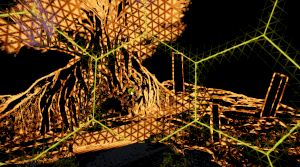
but there is something happening that I did not expect, the image is blurry? Do you have any idea how? I assume because of the sampling?
Can you correct my understanding: I thought that this wouldn't change anything about the final image, as in my idea it would just return back the value at the point?
Hmm, maybe it has something to do with texel size...
in any case, you have been very helpful dlich! Thanks for taking the time. If you don't have answers to my final questions, don't worry about it.
It should, yes.
aiaiai
I mean, it should only return the color. Not modify it in any way.
If you need further help, share more info on your current setup and how you got it working.
Okay, so I should have done something different before, because it works now by referenceing _ColorOpaqueTexture in my created _MainTex Texture2D and then Sampling that with the default Sampler Node using _MainTex.Sample(Sampler, uv.xy)

I put it in string mode for now to keep it simple
this is before and after applying, as you can see it becomes blurry


What exactly is getting blurry? The only difference I see is the pink capsule on the left screenshot. I should note that I'm looking from mobile.
try opening them, it should become clear, don't worry about missing texture dude
What is the shader supposed to do?
And what object is it applied to?
Ah, ok, I see it's a bit blurrier.
Is that a full screen shader?
eventually some iteration of anisotropic kuwahara filter, but currently just trying to sample scene colors correctly :p

this is how I put it in the pipeline
Share the custom function node code and the whole shader graph.

don't mind the other input vars
only thing that are being used you can see in the Body of the custom node
which is _MainTex, Sampler and uv
- Try setting the sampler filter to point.
- Check that the sampled texture and the render target have the same resolution in frame debugger.
There might be something in the custom node function too.
point makes it look less, but still blurry
should look into how to use frame debugger
I'm going to bed dilch, thanks for the help though
looked like _CameraOpaqueTexture had a smaller resolution
I used _BlitTexture, because I found it there, no clue what it is
looks to be fine now
@kind juniper just fyi
does someone had this problem before?, i dont know how to fix this and i dont know how this happens

hi im doing a project which requires a melting effect, like 3d words being melted into a pool of liquid, is there any free shader assets for this?
Share the error details. Is there a callstack? Is it related to your custom shaders?
still some bugs, but it's coming together:

I dont know, i tried doubleclicking it and it did nothing, i dont know what to do
since my project has alot of shaders
Click it once and take a screenshot of the whole console window
Hi all. I asked in ASE discord but, this is more about concept of shader itself so..
Im trying to do vertex offset. Is it possible for the offset value to get info of another pixel, given i know the pixel's uv coord?
To put it simply : No.
This could be done with geometry shader, but it is not something that is implemented in ASE or Shadergraph.
What could be done though is to "bake" the offset direction/center into additional data on the mesh, like vertex color or an additional UV channel.
I tried to do that. The tut i followed does this, based on uv coords. Top left is xy -.5,+.5, bot right is +.5, -.5
But this requires each quad's uv to be fully square (like the result of blender's UV>Reset), but this requires all the quads to be "upright" when modelling
I guess it's still workable
That's a different technique
Yes, the tut does the uv dictated direction. Needs to be upright
What i wanna do is instead, expand outwards, regardless of uv coord
Baking the center point of a polygon into custom vertex streams does not require using existing UVs to try to figure out where the center should be
Hello! If anyone has the time, I'd be super grateful for some help with a shader I'm trying to create.
I'm not very good with shaders, but I'm trying to create a couple of shaders for use with a custom pass. I want wetness and rain drops and stuff to appear on objects and on the ground. I'm currently using a slightly modified version of a rain shader included in Shader Graph's Production Ready samples with a DrawRenderers custom pass for objects and props, and for the terrain I'm using a fullscreen custom pass with the fullscreen wetness effect found on this GitHub: https://github.com/alelievr/HDRP-Custom-Passes
I'd like the effects of rain drops and puddles that is currently on the props to be happening on the terrain as well, but simply using a DrawRenderers custom pass on the terrain wreaks havoc on all the trees and grass, and also doesn't seem to work on the terrain itself for some reason. The fullscreen wetness effect gets around this somehow, which probably has to do with how it only affects flat surfaces without rendering on top of specific objects, but this is very much where I start to get lost.
What I'd like to do is to get the rain drop and puddle effects from the productions ready samples "into" a fullscreen shader like the one I'm already using, so that it can be used on the terrain, but I can't really make heads or tails of the shader graph, and I was wondering if somebody could help me understand what needs to be done? I'm including both of the shaders here.
I understand if it's too complicated to help over text in Discord or if it's not possible to combine these effects per se, but I wanted to ask. Thanks in advance!
GitHub
A bunch of custom passes made for HDRP. Contribute to alelievr/HDRP-Custom-Passes development by creating an account on GitHub.
Why I don't see any preview in "Main Preview" like the tutorial I'm following please ? 🤔

This is the tutorial, he sees a sphere in the Main Preview, then he switches it to a custom model, when I try to do the same still nothing appears 🤔

If the shader is currently transparent because it has a transparent texture or something, then nothing appears. You can also try right-clicking in the main preview window and selecting what type of mesh you want to see. Otherwise I'm afraid I don't know.
It is set to transparent with 0.46% opacity like in the tutorial and I already set the mesh I want to see in it but still nothing appears, even the default shapes (sphere, cube, etc...) don't appear 🤔
Actually, sometimes building a complex shader breaks the main previews or other previews. Same thing happened alot with me too
Here it's not even a complex shader, you can see the tutorial here : https://youtu.be/peY9VipZ74o

Learn how to make a Ghost Placement or Hologram Shader in Unity ShaderGraph. You'll learn how to create procedural scan lines as well as the edge glow (fresnel).
👨💻 The full project for the Chicken Defense Microgame is available on GitHub for FREE: https://github.com/llamacademy/chicken-defense
🏷️Save 25% on the ultimate C# IDE: JetBrains Rid...
Yea, unitys previews are broken for some reason
Found how to solve the issue 👍
Great. I would also like to know how.
Maybe that's possible, but tris that share the same vertices will need "center of face pos" info for every tri possibilities?
While being in the shadergraph window > Click in the top right of that window on the 3 little vertical dots > Enable / Disable UI Toolkit Live Reload.
I have no clue what option does but by doing that it solved my issue

There would have to be multiple vertices
Split edges basically
I need to make a shader/effect that makes a trail for the ray of my radar, this is the ray in the UI, and I also show my current non-performant implementation. https://streamable.com/a9ui5i
How could I make a trail UI effect in Shadergraph? Would I need to save the previous texture to a texture, then access it in the next frame? How could I make sure there isnt a gap inbetween segments of the trail, or could I avoid segments altogether?

My guess would be to make a 2d line texture with 1 point in the center and the other at the top that rotates based on a uv rotated by time * your speed modifier
I have a shader that uses the dot product between the normal vector of a flat mesh and the camera view direction. When I look at the mesh from an angle of 0, the value is full intensity, and when I look at it from an angle of 90, the value is at 0. How can I make it so this rate is controllable? So for example, I rotate the camera 90 degrees and go from a value of 1 to 0. I want to be able to alter the rate in a way where I can go from 1 to 0 over 45 degrees instead.
But that leaves the problem, how can I make sure the trail is blended correctly so it doesn't look like it has gaps?
One thing for sure, it cant be handled only in shader.
You can use rendertexture and trail renderer. But that might unnecessarily complicate things up.
You can also use texture blitting for the trail and make it fade, then you'll need make a radial shader that takes angle parameters to be used to determine how wide is the 'trail'
You can use existing radial progressbar as a start and modify it. There should be some laying around somewhere on internet
but thats how dot product works...
of course, you can always remap the result using cosine or somethng
like
x = cos(dot(vec, dir));
I know it's how it works.
https://i.imgur.com/MpCxh5O.png
So I'm trying to paint onto a texture mask, but I'm not understanding why the values of my brush here need to be greater than 1 if I'm working in UV space. Can someone correct me on this because even as is, it seems like I need extreme small values even after 1 to paint minor pixels.
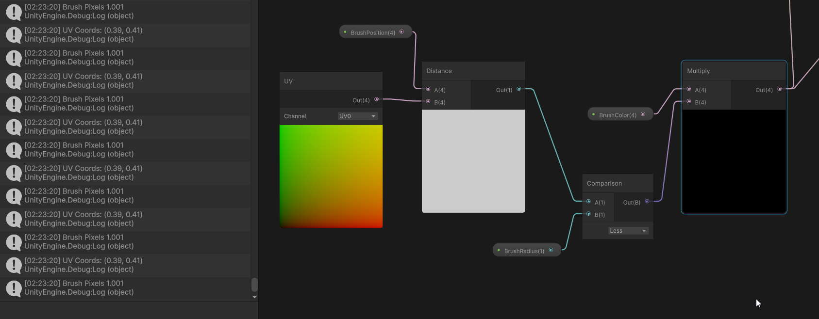
BrushRadius here is brush pixels^
Ah, actually doing distance between vector4s seems to be the problem. Whoops
Hey everyone, I'm trying to use vertex colors from Blender in Unity, but they are not showing up correctly.
how to solve it
Firstly make sure that they are exported correctly. You can check this using model importer configuration window:

I used this setting while exporting from blender

With a shader, you shouldn’t have those options since it is calculating all the values in between
(I’ve never actually tested this or similar but I’m confident that this would work)
Do you know how to use shadergraph or equivalent?
https://i.imgur.com/K1bSZb8.png
So I'm kinda scratching my head at this one. So my idea here is to use alpha values to determine if the painted values should be erased or not, but it seems that once I erase these values once, I'm not seeming to be able to paint again. It feels like I've values going into negative... can you even encode textures with negatives?
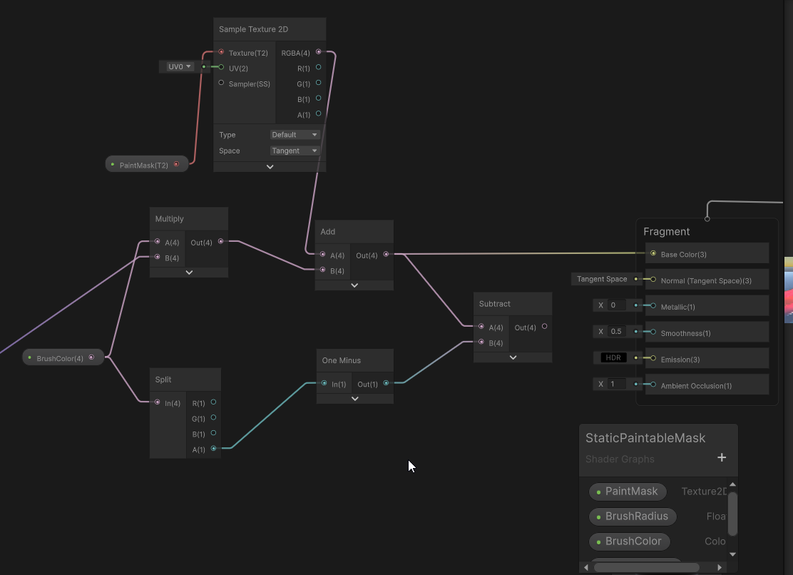
Technically, yes, floating point format texture can have negative values.
Yeah I just changed to a floating point so that must be what's happening
You could use a Max node after the subtract to avoid going bellow 0
Hey everyone! I'm currently participating in a game jam and still fairly new to game development. Today, I created a mesh in Blender and used vertex colors to blend materials. and in unity I did this after learning something from online , but its not working , can you guys help me with this?
thanks in advance!

What precisely is not working ?
What does it look like on your mesh ?
well , in blender I painted with blue and red , and its showing in unity , but I want to set one texture for the blue part and another for red , but none of them is showing up
If you have only two textures that you want to blend with the lerp node, use only the red channel, and consider that no red = tex1, red = tex2.
You need to take only the red value of the vertex color (from the split node).
And I recommend to expose the texture as properties (in the blackboard) of the shader.
like this?

Yes, and expose the textures as properties.
right click -> convert to -> property ??
Yep
still lookin like this

I mean after saving its becoming complete white
sorry my bad! I didnt assign those textures in inspector
thank you for the help!
Does anyone know how to use Texture2DMS in shaders?
Texture2DMS _BlitTexture;
SamplerState sampler_BlitTexture;

fixed4 frag (v2f i) : SV_Target
{
    fixed4 col = _BlitTexture.Sample(sampler_BlitTexture, i.uv);
    return col;
}
(Above code doesnt work because Texture2DMS doesnt have a Sample function)
I found the docs for Texture2D but not Texture2DMS
https://docs.unity3d.com/6000.0/Documentation/Manual/SL-SamplerStates.html

Best to look at the HLSL documentation for this.
https://learn.microsoft.com/en-us/windows/win32/direct3dhlsl/sm5-object-texture2dms
It doesn't appear to be possible to use texture samplers with it. You can only read pixels directly and each individual sample.
Thanks for the doc link im trying to fix this error
"A multisampled texture being bound to a non-multisampled sampler. Disabling in order to avoid undefined behavior. Please use Texture2DMS in the shader."
but Load looks promising
And you haven't seen this error before or know why it's happening?
Im trying to get the depth texture into a material shader through the rendergraph
when I pass along the color texture it works fine
but for the depth texture I get that error
When using MSAA, there is not a single depth value for each pixel, but multiple samples. 4 when using 4x, 8 for 8x, etc.
So you have to decide how you want to sample it. There's no one correct way. You could read all the samples and choose the closest depth. That would be conservative sampling. Or you could read a random sample or always the first sample.
The issue im running into rn is I dont even know how I can sample it in the first place
The main difference is you have to use integer pixel coordinates, not float UVs.
Is there a way to turn off the msaa in code (its already turned off in the universal render pipeline asset)
    public override void RecordRenderGraph(RenderGraph renderGraph, ContextContainer frameData)
    {
        UniversalResourceData resourceData = frameData.Get<UniversalResourceData>();
        UniversalCameraData cameraData = frameData.Get<UniversalCameraData>();

        if (cameraData.camera.cameraType != CameraType.Game)
            return;

        var desc = cameraData.cameraTargetDescriptor;
        desc.depthBufferBits = 0;
        desc.msaaSamples = 1;
        RenderingUtils.ReAllocateHandleIfNeeded(ref m_OutputHandle, desc, FilterMode.Bilinear, TextureWrapMode.Clamp, name: k_OutputName );


        Shader.SetGlobalTexture(m_OutputId, m_OutputHandle);

        TextureHandle source = resourceData.cameraDepth;

        TextureHandle destination = renderGraph.ImportTexture(m_OutputHandle);

        if (!source.IsValid() || !destination.IsValid())
            return;

        RenderGraphUtils.BlitMaterialParameters para = new(source, destination, m_Material, 0);
        renderGraph.AddBlitPass(para, "BlitToRTHandle_CopyColor");

        resourceData.cameraColor = destination;
    }
this is the ScriptableRenderPass code
I don't know, I would think the depth texture wouldn't be multisampled if it's disabled in the URP asset.
I fixed it by using resourceData.cameraDepthTexture instead of resourceData.cameraDepth
I know how to use shadergraph, and I know a little bit of glsl
The ray is currently just a png that rotates, but I use that rotation value so i can know when to display the scan icons, like this:

The reason I want to make a trail is because when the radar first becomes enabled, the ray isnt moving, and this current ray texture looks like it has a trail, even when its at rest.
The trail can be created in shader using a radial gradient and the problem of the ray having a trail when stationary can be fixed by dynamically adjusting the length of the trail so it's zero when at rest and scales up as the ray begins to move until it reaches its max length.
For terrain, why can a shader not be put into a Mesh Renderer component like a plane or cube?
Also now that I applied a shader onto my terrain, Adding a layer and trying to paint the terrain with it doesn't do anything
Unity terrain is a specific type of renderer that requires the material/shader to use it's splats data (the terrain layers mask). In the built-in render pipeline they are applied by group of 4 layers.
You can check the source code of the shaders here :
https://github.com/TwoTailsGames/Unity-Built-in-Shaders/blob/master/DefaultResourcesExtra/TerrainShaders/Splats/Standard-FirstPass.shader
https://github.com/TwoTailsGames/Unity-Built-in-Shaders/blob/master/DefaultResourcesExtra/TerrainShaders/Splats/Standard-AddPass.shader
https://github.com/TwoTailsGames/Unity-Built-in-Shaders/blob/master/CGIncludes/TerrainSplatmapCommon.cginc

That depends why you would need to "build a shader" for those
All render pipelines already support PBR mapped shaders, give or take some features
how would I use a radial gradient?
Looks like it's sometimes called a conic gradient. If you think of the trail as the start of the gradient and just rotate it to follow the ray, then you can just pick how long to make the trail by scaling the gradient.

and how do I properly assemble the texture?

You mean like this?

Yes. Now you just need to rotate it, either by rotating the UVs first or maybe there's some other way to do it. Then, scale and clamp the value and apply a color to it
How could I scale the gradient so its shorter? I was thinking to clamp it, but that gives the wrong result. I tried dividing it, but that also decreases the light values.
Found something that works

but it requires negative numbers
which decrease the size
Screen works better
I think you'd want an inverse lerp. Basically choosing the subset of the gradient to be the whole range. So A might be 0.9 and B would be 1. Then you'll get a gradient that is just 10% of the gradient.
You mean like this?

Yes. You might need a Saturate node after Inverse Lerp to avoid negative values.
I have the length variable clamped between 0 and 1.
Still, Inverse Lerp doesn't perform any clamping so any T value less than A will produce a negative value.
Oh I get it.
Now I kinda just need a way to change the length variable via c# script.
You have most of it there already
Smoothness is mildly tricky because it's inverted roughness, and must be on specular map alpha channel (or base map alpha, or metallic map alpha)
Meaning you need to use an image editor or a channel packer to invert roughness and store it into one of those alpha channels, depending which one is set to be in use
How do I do that? Can you tell me how to do that?
Do what exactly?
Photoshop to make an alpha channel like you said.
In PS you'd give the chosen map an alpha mask, paste the roughness map into it, invert its colors, apply mask into alpha channel
maybe there's some kind of video?
Wall_Paint_qj2luvs0_2K_Specular I open it in photoshop?
and then I add Wall_Paint_qj2luvs0_2K_Roughness to the alpha channel. ???
I am trying to overlay a texture onto another, and it literally works fine, but most of my sprites are packed (resource type "multiple") and it overlays the texture over the whole texture pack instead of over the visible area, how do I overlay the texture over just the visible part?


the example pack is split like this for reference, but it will apply to sprites coming from packs of many different layouts

Does anyone know whether "Fadeout to Grey" improves performance when textures are viewed at from a distance if used on all normal maps?


In the documentation it says it's used for detail maps, but gives no clue about whether this is mainly about visuals or saving performance. I would assume or hope that if the texture is just displayed as grey, it does not have to be rendered anymore, but since it's a transition and it's not mentioned anywhere I am not so sure.
I'd assume that there's no effect on performance whatsoever. It's probably just a lerp between the texture color and a flat color in the shader.
There might be a condition or something, under which it doesn't sample the texture at all, but honestly switches might be worse than sampling a texture performance wise. So I'd think it's just sampler always.
Is it intended that Unity's Gradient noise generates values that can go below 0, or is it just something that got fixed in more recent versions. (using 2022.3.40f1)

According to the doc and the generated code example, yes, it is intended, as the fp variable isn't normalized, and can result in dot operations that can go bellow 0 or over 1.
Isn't that misleading then?
I'm sure there are tutorial videos for editing the alpha channel in photoshop
Like I said it requires using the alpha mask operation
And don't forget to invert so the roughness becomes smoothness
Indeed
aight, that's what I wanted to know
If I'm not wrong, the output range is potentially something close to (-1;2), which seems extreme when looking at the shader output. I'll do some tests to check.
I don't think it falls below -0.1 and doesn't go above 1.1
Yeah, it would be weird if it was the case, that's why I want to double check 😅
Is there any preferred resolution for Gradient textures?
Not really.
If in doubt, saturate 🙂
Hey, I'm super new to Unity, following a tutorial for some blood effects and having some issues. Here's the video: https://www.youtube.com/watch?v=0PY5oV7yU4Y
At about 3:30 he starts making a UV thats connected to Alpha Clip Threshold to give the particles a "death" time, and when I do everything like in the video literally NOTHING changes. I'm on unity 2022 and did have some trouble finding everything that he uses in his 2019 version, but I got URP and found all the needed settings. Anyone have any idea how to fix this?


I take blood showers every morning and I highly recommend you to do the same! In this video you will learn how to create your own spectacular blood fountain with the use of PBR Shader graph and particle system. No textures required (beside the default Unity particle sprite as a mask), everything is done proceduraly. Don't forget to have fun!
SU...
Is it possible to update the name of the outputs of subgraphs when embedded into other graphs?
Oh, ok there it goes. Had to recompile the shader
Documentation is wrong, intention was to avoid unnecessary saturates in the prodecural nodes (do them yourself if needed).
I'm mostly new to unity with background in programming, and after I read the documentation about shaders, I wanted to challenge myself to do a postprocess in built in pipeline, in which some particles move around on the screen. the first idea that I had is to use a compute shader where I pass a buffer of particles properties( like the position) and compute the update , and then update the particle buffer of the postprocess shader in preRender image, but I was wondering if there is a more efficient method because I think with this approach I pass a buffer gpu to cpu and then gpu again every frame. is there a way to update the buffer on Gpu and then just use the buffer already in gpu inside the shader
You can just bind the same buffer to a pixel shader.
Just make sure the compute shader is done by that time.
Ideally you'd need to use barriers (assuming unity doesn't do it for you).
mm I don't quite get the binding concept, if it is ok for you can you guide me to some documentation on the matter especially in unity context, I'm prone to learn and search by myself
and by pixel shader you mean the shader that handles the post process effect?
You can bind a buffer to a material using Material.SetBuffer.
You can also bind the same buffer to your compute.
You don't have to do this every frame, bind it once to both, be sure to execute the compute before the post process, and the post process shader will be able to use the buffer data that was updated by the compute just before.
ohh, I didn't know that there was a concept of reference with set buffer
the documentation doesn't seem to state this fact
regarding the fact to be sure to call the compute shader before , is it enough to call dispatch and then use blit
Yes
I have no idea why my shader creates border when i use Lookup table.
There is no mipmap/ anti alias/ compresion , used point filter
tried both .asset (RGBAFloat 0-255) and .png ( RGBFloat 0-1)

But what is the mipmap/aniso/filter setting on the lookup texture ?
they are settings in import setting/ asset setting
Can you show the import settings of this texture ?

here

this is idTexture (in both type: asset/png. I tried both)


In my general image. There is no anti alias/ mipmap or anything like that to create border like above. I dont know why it create borders between color zones
You could also try to force the sampler stater to point/repeat in shadergraph with an inline sampler node.
Or force the LOD using the SampleTexture2DLOD node.
yes. LOd, it is. I almost forgot it, thank so much
Do u know why Lod make it different ? Like in vertex animation or in this case. It is just different for no reason.
In this context it refers to the texture Level Of Detail, aka Mip Level.
but i turned off mip map
It seems like this one has mips (as there is a mip preview slider)
So when sampling it, at the borders of the flat color zones, the UV varies greatly and it goes to sample a lower mip level.
IDK how you got that texture without import settings. Did you generate directly a texture and store it as an asset file ?
i use code to generate the texture2d but i use krita to paint idTexture
i also use code to convert from .png to .asset
But why ?
.asset allow integer value. easier to work with
I think something in the process did add mips again then. Anyway, you got your solution 🙂
Hey, I cannot get my vertex colors to show up in unity after painting them on a mesh in Blender and exporting as an fbx. I've tried all the tutorials making custom shaders, and making shader graphs to link the vertex colors but nothing seems to work. Does anybody have any experience with that?


not sure where to go next

hm maybe this has something to do with it

Have you confirmed by looking at the mesh in Unity, switching to vertex colour mode?
I don't think I've seen something like that yet, Would that be somewhere under inspector?
Click on the mesh from the project or hierarchy view.
You should see something like this

Click on the Shaded drop-down. I think there's a vertex colour in there
@primal hatch Not seeing the model like you have for some reason

Click the bar at the bottom

Oh my gosh there it is

hm yeah the colors are there

Wish I could help you with the shader part but I'm not great there.
All good, thank you for the help at least I know the data is actually there
If you are using URP or HDRP you cannot use surface shaders - those are Built-in RP only.
For other pipelines it's recommended to use shader graphs. Vertex Color node should work, make sure you're saving the graph and applying the correct material
thank you! got it working

using shader graphs
just need to figure out why theres no shadows or anything
quite tragic, must be a setting with the material that gets rid of the lighting


crikey i did it, just had to change from unlit to lit. ty all

I am learning a bit about using compute shaders. Does the Load function on a Texture2D have the ability to provide a mip value? so to give which mip to load from? i can't find info about that.
Below is my shader so far. I am trying to create it for downsampling the depth texture into lower resolution mip maps.
#pragma kernel CSMain

Texture2D<float> Source;
RWTexture2D<float> Target;

[numthreads(8, 8, 1)]
void CSMain(uint3 id : SV_DispatchThreadID)
{
    int2 targetPos = id.xy;
    int2 sourcePos = targetPos * 2;
    float p1 = source.Load(int3(sourcePos, 0));
    float p2 = source.Load(int3(sourcePos + int2(1, 0), 0));
    float p3 = source.Load(int3(sourcePos + int2(0, 1), 0));
    float p4 = source.Load(int3(sourcePos + int2(1, 1), 0));

    float minDepth = min(min(p1, p2), min(p3, p4));

    Target[targetPos] = minDepth;
}
Yes, would be the third component in the int3. Currently you only use mip level 0
https://learn.microsoft.com/en-us/windows/win32/direct3dhlsl/dx-graphics-hlsl-to-load
ok thanks, so it should be possible to read from, for example mip 1 and write to mip 2, of the same texture at the same time or probably not?
I have been trying to get the depth texture mips to generate properly for a while now but it's not really going well. I am not really experienced with this area.
The result would be texture where each mip holds the closest depth of the previous mip.
ok, i THINK i'm on the right track but not certain. I'm trying to make a disintegration shader that goes from the mesh's rear (-Z to it's front +Z). I want there to be a section of noise that makes it look like it's burning and then the section behind this "tail" should be completely invisible -- i'm going to add a particle effect too but for now i just need to get the "paper burning" and alpha clipping worked out.
Here's the graph so far

and this is my running theory, is that right?

i can get the "hiding" part to work, and im only using the base color to visualize what i'm doing. i'm not really sure what nodes i'm looking for but i THINK i need to re-code the Z position value back to blue so i can use some color masks? i think
nvm got it
Is there any way to sample a color that’s off screen?
That pixel would need to be rendered somehow. Only way I can think of is to render at a higher resolution than the screen actually is, but that sounds pretty ridiculous.
What are you trying to solve?
Sample from what? From the screen color? From something else?
Sorry for the super late response. It would be a screen sample. I’m making a lending/distortion effect, which means at certain positions I’d need to sample a point off screen
Likely screen color
But maybe there’s a diff way to do it
For such effects you'd usually wrap sample(sample pixels from the other side) color.
Or clamp. Or just use some predefined color
It's kind of a design choice.
Alr, clamp looks kinda goofy cause it’s so far offscreen and so would a predefined color. I’ll try wrap. Thanks!
Has anyone made a template for a custom URP lit shader yet?
Create -> shader graph -> urp -> urp lit shader iirc
An actual hlsl shader though, not a shader graph because shader graph doesn't work for some use cases
I'm planning to copy the LitShader, each of the pass headers and a few other headers
then adjust material properties, and make it possible for a single hlsl file to provide the specific shader vertex attributes, varyings and vertex and fragement functions
But from what I gather, this is the same thing anyone who needs custom shaders without shader graph is forced to do currently, I don't want to reinvent the wheel if I don't have to
With rendergraph is it possible it doesn't really handle loops well like below? I have a computeshader that samples from a mip level and can write to a different mip level. i also make it swap the colors rgb -> brg for example to debug. I have made 3 passes that downsample to the next mip outside of a loop. those work fine. but the passes called inside the loop seem to fail.
int mipCount = 1 + Mathf.FloorToInt(Mathf.Log(Mathf.Max(cameraData.cameraTargetDescriptor.width, cameraData.cameraTargetDescriptor.height), 2));

for (int mip = 1; mip < mipCount; mip++)
{
    using (var builder = renderGraph.AddComputePass($"ComputePass", out ComputePassData passData))
    {
        // pass code here.
    }
}
Can it be the loop being the problem?
I think i might have found my issue. i am using the incorrect mip levels sometimes because of confusion.
why is this happening, i thought it would make the black parts white only?

apparently i can switch the color and now it works as expected, but i want the other way around

(0,0,1) + (1,1,1) is still larger than (1,1,1) so will display as white
You want a Lerp, not just Multiply+Add
e.g. https://www.cyanilux.com/tutorials/color-swap/#lerp
just done that, thanks

how do i make it so the white parts appear
smaller and with more amount
in larger planes
but quite the opposite in smaller planes if u get what i mean
right, i can just turn the values into properties and change as i like
hello. i am making a 2d unity game with pixel art sprites. im currently using a material for the sprites with the Sprites/Default shader. ive recently needed to use a custom-made shader, however, i need to be able to use the "pixel snap" feature that is on the Sprites/Default shader. how do i add that feature to a custom shader?
whats the best way to apply different distortions to different layers in 2d? Previously i only had 1 distortion so i made everything that needs to be distorted be rendered first, applied the distortion using camerasortinglayer texture, then rendered everything else on top. now, however, i need certain layers to have 1 distortion, certain layers to have a different one, and certain layers to have none at all
using URP btw
The supported workflow would be to use shader graph and start with one one of the sprite shader graph assets
and that would have the pixel snap feature?
I assume you mean support for the pixel perfect component?
I'm not sure what other type of pixel snap you might mean

this is the pixel snapping thing i mean
This is a built-in render pipeline sprite shader feature, which I'm not really familiar with
The shader works in URP but it's not officially supported
What's it meant to "snap"? I can't find any documentation or examples about it
A point filtered sprite by its nature snaps its texels to screen pixels anyway, but without pixel perfect rendering neither type of snap seem to be able to guarantee correct appearance
The source can be found here, and someone better at shaders than me might be able to parse what it does exactly
According to forum users the function can be copied and implemented in an URP shaders and it'll work
But I'm still a bit confused because multiple people cite Sprite Atlas as a solution that works instead
Which has nothing to do with any type of snapping
But it does include a padding option, which does eliminate a specific type of color bleed issue for tilemaps
Sprite Atlas is not required for padding either though, but it's convenient that the tool is there
Hi, when I try to build my game, one of my shadergraphs throws this error message:
Program 'frag', error X8000: D3D11 Internal Compiler Error: Invalid Bytecode: Negate modifier not allowed for operand #5 of opcode #267 (counts are 1-based).
Compiling Subshader: 0, Pass: Universal Forward, Fragment program with PROCEDURAL_INSTANCING_ON
Platform defines: SHADER_API_DESKTOP UNITY_ENABLE_DETAIL_NORMALMAP UNITY_ENABLE_REFLECTION_BUFFERS UNITY_LIGHTMAP_FULL_HDR UNITY_LIGHT_PROBE_PROXY_VOLUME UNITY_PBS_USE_BRDF1 UNITY_PLATFORM_SUPPORTS_DEPTH_FETCH UNITY_SPECCUBE_BLENDING UNITY_SPECCUBE_BOX_PROJECTION UNITY_USE_DITHER_MASK_FOR_ALPHABLENDED_SHADOWS
Disabled keywords: DEBUG_DISPLAY DIRLIGHTMAP_COMBINED DOTS_INSTANCING_ON FOG_EXP FOG_EXP2 FOG_LINEAR INSTANCING_ON LIGHTMAP_ON SHADER_API_GLES30 UNITY_ASTC_NORMALMAP_ENCODING UNITY_COLORSPACE_GAMMA UNITY_FRAMEBUFFER_FETCH_AVAILABLE UNITY_HARDWARE_TIER1 UNITY_HARDWARE_TIER2 UNITY_HARDWARE_TIER3 UNITY_LIGHTMAP_DLDR_ENCODING UNITY_LIGHTMAP_RGBM_ENCODING UNITY_METAL_SHADOWS_USE_POINT_FILTERING UNITY_NO_DXT5nm UNITY_NO_SCREENSPACE_SHADOWS UNITY_PBS_USE_BRDF2 UNITY_PBS_USE_BRDF3 UNITY_PRETRANSFORM_TO_DISPLAY_ORIENTATION UNITY_UNIFIED_SHADER_PRECISION_MODEL UNITY_VIRTUAL_TEXTURING USE_LEGACY_LIGHTMAPS _DBUFFER_MRT1 _DBUFFER_MRT2 _DBUFFER_MRT3 _SAMPLE_GI _SCREEN_SPACE_OCCLUSION _WRITE_RENDERING_LAYERS
i thought this would move my plane up and down continously but thats not happening, any help?

i fixed it by using a sine function, but i want to know why sine function was able to fix it
I installed URP into my project, assiged URP pipline asset. I created a standard surface shader, but when I open it it is all errors. How do I make coding a shader compatible with URP?

URP doesn't support surface shaders
Officially you'd use Shader Graph
But writing the shaders is also possible
I want to make a shader that can stack all the textures into a single texture for character customizations.
I have six parameters: Top, Middle, and Bottom textures, along with three colors. I know I can apply color to each texture individually by multiplying them, but how do I combine all the textures into a single texture at the end?


Is there any way to extract a depth buffer at a certain step? Like if first opaque meshes are rendered an then alpha clipped ones, is there any way to extract the depth at the in-between point?
Sounds like depth-prepass. Not entirely sure how to go about that in the shader, but usually can grab that behaviour with pipeline render objects
Why do my teeth have weird boxes around them when I put a material on, I've highlighted their colliders so you can see it
Are there any plans to properly support writing shaders again?
I've copied the URP lit shader and modified it to use my own 'surface shader' code from a hlsl
but how would I actually go and hide all the boilerplate so making new shaders with this format becomes easy?
The shader itself is a mess of passes, includes and pragmas
I don't know what you mean by "properly" but there's work on something called "block shaders" that may be what you want
Well unity does not seem to care to allow users to create custom shaders that work with URP without shader graph
Afaik the docs are barely existent and only explain basic unlit shading
Cyanilux did the work to make a template shader that works with URP (wish I knew that before manually wafting through unitys lit shader)
https://github.com/Cyanilux/URP_ShaderCodeTemplates/blob/main/URP_PBRLitTemplate.shader
If I copy this and go in and manually customize all the passes I can create a custom lit shader, but that's obviously a horrendous workflow
Unity 6 URP Shader Graph
Unable to re-check 'Show In Inspector' after unchecking it

nevermind., had to select 'Per Material'. silly mistake
In this graph setup, the position Y value can only increase and never decrease, but when you add the sine function it made the Y offset loop in the [-1;1] range.
There is not ETA for it yet, but this is the goal for block shaders.
After the textures are tinted with the matching colors, you can use Lerp node to combine them, but you will need a way to mask the textures for the T input of the lerp.
hello can someone help to make a custom shader graph, i need to make a specific shader for my map the mesh don7t move stretch or anything, i hand painted a series of normal map and no built in shader can actually make them work
What are you trying to do ?
im trying to make a custom shader graph for one of my material, the hand painted texture have been made in the object normal space, and unity built in feature doesn't render them correctly
You mean, "tangent" space ? Have you imported the map as "normal map" in the import settings ?
yes i did inport them as normal no worries but i dont want the shader to use the tangent space
i want the shader to use object is it possible ?
Only the HDRP/Lit shader has a normal space mode dropdown, For other pipeline, you need to use shadergraph and in the graph inspector you can change the "Fragment Normal Space"
Or just create a shadergraph ^^
yeah i know how to create a shader graph but not for this very topic lol
Well, you just have to sample the normal and plug it into the normal output
And change this

i made a mesh in the 3d software, i painted the normal map over there
i tried that also didnt work ...
raaa lets dive back in then
One thing that is a bit confusing in the discussion is that you mentiont that you imported the texture as normal map, which kind of considers that the normal is in tangent space, but you want to use it in object space 🤔
nop i painted the normal map in the object space
Then, don't import it as a normal map, but default texture without sRGB
actually i could bake it into any space possible but i want the object one
aaaa
my computer dont like the hdrp
not at all
mmm remy maybe it would be easier if i can show you?
Can't. But like I said, import the texture as default texture without sRGB, change the fragment normal space in the shadergraph, and it should work.
I can't do a screen share, but feel free to show screenshots of the importer/graph if this doesn't work.
It mean, that's a simple and "common" setup, and should work. If you share some screenshots of the setup I might be able to help fix it.
Oh, forgot to mention that the normal map also needs more nodes setup in shadergraph.

Looks like it would be useful 👍
anyone got an idea of how i can make a highlight shader, similar to how PPT Chapter 4 does it?
cuz i got small items in my game and in the dark its impossible to see, has to be visible in the dark. i dont want lighting to affect it
https://fxtwitter.com/aDrive_tK/status/1902917793378402619
So in this vid there are some holographic cards, and what I specifically want to try to replicate is the "sheen" on the card. The fact that it displays a reflection.

The NEW Premier frame Spirits for the Dallas Open!
︀︀
︀︀They look AMAZING!
💬 7 🔁 7 ❤️ 134 👁️ 6.0K
Specifically how the light seems to sweep across the card.

Obviously do not want it to reflect something real.
Most of what you see is achieved by specular reflections
You'll want a skybox or a cubemap of a room so there's something to reflect, otherwise they won't have any reflections
Then with the specular material workflow you can make a specular map and a smoothness map to control the color of the sheen and its sharpness
Normal maps probably aren't necessary but they would let you bend the reflections as you want
The holographic decals are trickier, for those I'd look into guides about making those specifically
You say the holographic decals are trickier but I already got them 😛
I just have a texture and a normal map for the symbols.
And then do a bit of dot product math with the normal map vector and the view direction to decide if they should be shining.
Yea, the basic sheen doesn't require any of that
Plain old specular and smoothness maps are enough
It's just textures all the way down, isnt it 😔
Implying also specular PBR shading
Which you have in URP via the Lit graph
I'd like to build this up from Unlit, mostly for the sake of learning.
I know that Unity has a whole PBR shader graph reference project.
They do?
I could use it
I only know of the importable shader graph samples which include an incomplete one
yep

From Feature Examples sample?
think so
It has most of the lighting calculations but not all, and it was never intended to be a full breakdown
Maybe you don't need everything, but if you do you have to refer to the the Lit shader source and convert it to custom nodes
Cyan already did that work here, though I'm not sure how up to date it is, some features like APVs were added afterwards
Hmm, I do want to make sure the math here isn't too strenuous since I want quite a few cards displaying.
@grizzled bolt Wait so what's the flow here exactly? Cubemap to define what is being reflected, specular to handle how it's displayed, smoothness map to break up the cubemap texture?
Yes
As far as I understand specular map is just color multiplication
Smoothness controls which mip level is sampled of the cubemap
But it also interacts with punctual lights and fresnel in ways that are a bit more complicated, in case you need those
@grizzled bolt Unity has a "Legcy Cubemap". Is there any... non Legacy Cubemap?
The legacy cubemap is an asset type
Non-legacy cubemap is a texture import setting
Shader Graph has a cubemap property, I assume this is for the legacy?
https://docs.unity3d.com/Packages/com.unity.shadergraph@17.2/manual/Property-Types.html#cubemap
It's for the cube textures
I assume legacy cubemap assets and modern cubemap textures are interchangeable
Both as properties and when sampling them
Legacy cubemaps have less features and cannot be compressed, there's not really a reason to use them
@grizzled bolt If I want the "reflection" to be a tiling noise, do I really need a cube map?
Won't need, but for it to convincingly look like a reflection it's the best and easiest option
Alternative would be to bend a texture's UV coordinates based on geometry normal and view direction in some way that resembles a reflection
Matcaps do that, but in their case if the texture doesn't resemble a sphere it won't really look like a reflection
Can I even apply a single tiling noise texture to a cube map?
seems like they'll be seams somewhere
There would be, up to you if it's too noticeable
There's also a hacky solution to import a 2D texture as a cubemap and force it into one of the cube configurations, such as spheremap
There will be distortion but it depends on the case if it's problematic
Like the documentation says you can also generate cubemaps inside of Unity, so you could throw random meshes into your scene to approximate the environment you want reflected and generate a cubemap from that
Hey, was wondering how I could pixelate this sine wave to match my pixel art textures, anyone have any ideas?


I have done something similar before, but only when I was able to modify UVs. Now, with this sine wave effect there is no UV input, so I'm a bit lost
ignore the gradient noise I was testing smthn
You can either posterize the input or the output of the sine, to have constant steps width or height :

I’ll try this out, thanks!
This UV may be everything I need, because I have a subgraph that pixelates a UV to match a texture resolution

For some reason I was using a position node instead 😔
How would I go about achieving graphics like this in URP? https://cdnb.artstation.com/p/assets/images/images/004/358/503/large/rafal-urbanski-sshot-01.jpg?1482914565
This must be a shader or something, as my own low poly assets don't look like this out of the box.

When did unity take _Emission parameter out of the sprite-lit-default shader? In Unity 6 it seems to not be working
is it still the case that you can't modify the vertex output for Canvas UGUI shaders? only pixel?
Did it have it before?
For as long as I can remember the officially recommended way to make an emissive sprite is to make a custom lit shader graph which lerps between unlit and lit (sprite texture multiplied by light texture) based on a secondary emission texture, or any shader logic you want
Plop those assets into scene, set up the lighting and liven up the colors with post processing
There isn't really anything "custom" there
You only need nice assets with good materials, and an understanding of how to do good lighting and post processing
In the past I used the Brackey's tutorial (https://www.youtube.com/watch?v=WiDVoj5VQ4c&ab_channel=Brackeys) which uses _Emission on the sprite-lit-default shader graph. But that's not working now and the guides I am finding all seem to have bloom outright controlling the glow effect using a custom shader. But I haven't tried using the sprite custom lit shader type yet. As you mentioned, I want lighting to have a play, not just bloom

In this video we create an awesome Glow effect for extra flare!
► Check out Popcore! https://popcore.com/career
● Download the project: https://github.com/Brackeys/2D-Glow
● Get Gothicvania Church Pack: https://assetstore.unity.com/packages/2d/characters/gothicvania-church-pack-147117?aid=1101lPGj
● Learn more about 2D Shader Graph:...
Secondary texture properties can have any name you define, it's not something in the shader
_MaskTex and _NormalMap properties are an exception to that
The nodes in the tutorial work for purely unlit sprites, but if you also want 2D lighting you need the custom lit method
Alright, thanks. I'll go that route then
This is the node setup that was in the official example
You can swap _MaskTex for _Emission or whichever
If it appears wrong with lights iirc you also need to plug a Screen Position: Default into 2D Light Texture Sampler's UVs
Hey people, I'm working on a compute shader that does the jump fill algorithm and I've gotten it successfully working on my main computer, problem is on my laptop where the output is just black.
Two things, The first part of the compute shader works normally, so I know that my laptop can use compute shaders, second the laptop is using integrated graphics and I know that might be producing the problems.
Hello everyone, Im new to the whole Shader graph thing.. I followed a tutorial on how to make water in Unity, now, im facing this issue I cant find an answer for, can someone help me find out what the issue is??
The bottle, plane and capsule arent supposed to be there, its like a reflection

I know it's a hardware issue I'm just not exactly sure where to look
I can provide the compute code if needed
ok nvm people i fixed it
I just had to change to texture format for some reason 😭
I guess the format isnt supported on this laptop??
Yeah, different texture formats have quite a few hardware limitations
You can use this method to check if a format is supported: https://docs.unity3d.com/6000.0/Documentation/ScriptReference/SystemInfo.SupportsRenderTextureFormat.html
Hey guys, I downloaded the material from Fab.com

Now how do I build it properly in the URP shader?

Updated my shader, but now i'm running into an issue where the wave effect is sampling over the whole texture, instead of over just the visible part, making some sprites fully invisible or fully visible, instead of an "overlay" over any sprite

How can I make this effect sample over the uvs of any particular sprite? If there is no simple & automatic way, I can add a vector2 offset that moves the effect on a material instance, but I would like to avoid that if possible for fear of jankiness
If the texture is always a grid of sprites like the preview, then the easiest way would probably be to make the effect repeat - which should be hidden later when applied to the sprite mesh.
Would Multiply the UV by (rows, columns) and use Fraction node
looking into it, thanks!
never used the fraction node before, how does it help here?

so I have a pipe system consisting of multiple game objects to form the curvature and what not. how would I go about creating a shader that simulates fluid motion that moves along the spline shape I made with these different game objects (the pipes i'm referring to)? i'm thinking using a shared material and using a world space shader but i'm not sure how to make it where each game object doesn't simulate different instances of the shader but rather all share one and form a clean fluid flow along the curves.
How to write a PBR texture shader?
Is it possible to write a shader that automatically tiles to an object scale across all 3 axes using only UVs? Or do you have to get into world position for that

In shadergraph, the triplanar node should handle this for you (i think)
is there a list of shadergraph blocks and their (mostly) equivalent HLSL code one would put?
You can right click on the nodes and open documentation directly to get linked to a page with information about it and what code that it generates in HLSL
ah I see.. though I did figure out how to do it in shadergraph...
Hi guys, does anyone know how to make the shader graph scale and maintain size instead of stretching if that makes sense
I followed a tutorial and this is what it looks like, I tried changing the position node to World instead of Object but that didnt seem to work.

how to make a UI outline glow? I cant find anywhere to start
texture emissive perhaps?
where there is a UI texture, and its edges have emissive
the simplest one is just to ~~add ~~ bake/draw the glow into the ui image/texture
I just added color to emission of a lit shadergraph and it kinda worked, but it doesnt respect the texture and the Image color


anyone? 😭
Didn't I already explain this process to you
has anyone had issues with custom shaders in VR before where they only render to one eye (in my case, left)


Hey, sorry about the ping, but it seemed like you had an idea for this and I’m still stumped
I was referring to a setup like this

But with the number of sprites in each row/column of the texture instead of (2,2)
This should work, I’ll try this out when I get home from work, thanks!
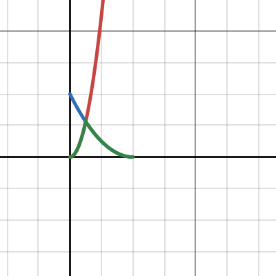
Hi. I'm using Sin node, but what if i want a quick when up, slow when down kinda curve?
Kinda like this pic, but i guess more curved rather than sharp
It's for leaf sway effect
It's kinda a math question, but i guess people here know some math?

Anyone know some resource on making specific curves?
Or maybe i should bake this curve values onto a texture?
It would be so simple if there's AnimationCurve node in shadergraph/ASE...
Baking into a texture is a solution, and if you wanted to you could implement animation curve into shadergraph. But the first option is a bit costly as it needs a texture sample, that can have a negative performance impact depending on the further use, and the animation (so, curve key points sampling) needs loop logic..;
The best is to find a formulat that can reprensent the curve that you want.
For example, you could get something similar with two square curves : https://www.desmos.com/calculator/p40t44dpza
Desmos
@amber saffron Hey Remy if you mind me asking, how exactly do these types of holographic effects work? Cubemaps for the reflection or something simpler?
https://www.youtube.com/clip/Ugkxx9vCSPMWI8XtauSpPtmUxTIdQjZieaZ2

YouTube
12 seconds · Clipped by SBroproductions · Original video "CS:GO Just Released The Most INSANE STICKER CAPSULE!" by TurboMotionZ
Well, you shouldn't have to do anything specific with a custom shader, in the case of this video it just looks are regulat flat planes with a lit material, high enough smoothness for, maybe some clearcoat, a reflection probe or a proper HDRI for the environment cubmap
Assuming I'm building something up from Unlit 😛
Well, still cubemap is the easy solution, but if the effect is specifically this you can make it simpler :
Since the camera is fixed, the cards are 100% flat, you can hack the reflection by using a flat texture mapped to screenspace UVs, and offset the UV with the view normal of the card.
I think I get what you mean, but would it be possible to show the graph for preparing the UVs? Sorry if that's a big ask.
Something like this :

I've seen something similar with View Direction in View Space. Makes sense, will give it a try. Any suggestions on how to blend this "reflection" texture with the main texture to get a soft streak like that?
Supposedly, it's a specular reflection, so an add node should be enough. You can also tweak and tint it by multiplying with a constant color before the add.
Specular is just add? Really?
Damn alright.
Well, it's more complex than that, and it depends on the BRDF but let just use add for now ok ? 😅
Always another layer to the rendering black hole
This is the curve that i want. How can i recreate this in nodes?

Rougly looks like 2 cos/sin curves, could be treated like this : https://www.desmos.com/calculator/tm1uutwtoy
If you want to save more on perfs you could search for a cos function approximation to replace the one I used here.

Desmos
Well the behaviour/motion looks aright. Now the question is how to make it look... not ass from a texture/blending perspective.
I'm not shocked by the result.
If you want to fancy it up you can :
- use a smoothness texture of the card to sample a different mip level of the texture : lower smoothness value => sampler a higher mip => blurier reflection looks rougher
- add a specular color texture to tint the reflection not uniformly
I understand the second point (make the reflection not just a white streak). I don't exactly understand the first point. I know what mips are (low resolution copies of the original texture, swapped out at increasing distances/angles to prevent jaggedness).
Mips are lower resolution of the texture. Lower resolution means blurrier.
When a surface if perferctly smooth, the reflection is sharp and clear, but the rougher it gets, the blurrier the reflection looks like.
So an easy way to fake the smoothness/roughness of a surface is to sample the reflection texture at a different mip level.
Could I not just bake this "roughness" into the reflection texture itself 🤔
Is there a way to specify the mip level of the sampler?
Is it the LOD version?
No, cause the texture moves, while the roughness info is on the card surface.
However, if you want to have a constant roughness on the card, youcan simply blur the reflection texture.
Yes 🙂
Assuming this is not what you mean. You mentioned a smoothness texture sourced from the card.

Well, the material needs to have a smoothness texture ^^
Sample it and use the value in the LOD input of the reflection texture sample node.
What the hell did I just do

Isn't it what you want ? ^^
Turned up that mult to like 70
Ya I'm just confused as to how this is even working. Brighter areas result in lower resolutions of the streak texture.
Well, the LOD input is a full number that goes from 0 to log2(texture size).
The bigger the texture, the more lod/mips.
And the unsaturated value of the color is probably not so much contrasted, so it needed a high multiplier to have effect.
As for why white areas result in lower resolution : white area = higher mip level sampled = blurier texture
very interesting
The blurriness appears like it moves with the streak as opposed to being a property of the surface. Is that expected or am I goofing?
Nah, for me it looks like it is properly on the surface
Might be an eyeball diff then. I'll trust you 😛
So I imagine that actual smoothness textures don't just plug into the LOD of another texture?
You mean, in other shaders and BRDFs ? not really ^^
But at the "root" of it, it is this logic.
btw, if you want something more independant of the reflection texture size, you can use a custom function to get the texture mip count :

how do I shift the line up and down?

Further on the left of your graph there must be a node that generated the gradient that has a UV input.
By adding or subtracting to the uv.y value, you'll shift all the other nodes up and down.
ah ok
Guys, who has good tutorial of done shader graph (screenshot) of vertix waving flag? I am tired. All tutorials don't work. I want to cry😭
That's not really how it works. If "none of the tutorials worked", screenshot is not gonna work either. Very rarely the tutorials are wrong themselves so it's more likely you did something wrong. Us giving you a screenshot is likely going to run into those same problems. It would be much better if you followed a tutorial of your choice and asked here once you had a specific problem we could help with.
aaa, nah, as always, it's work now x)
thx for answer
If anyone here is more familiar with shaders I'm curious if the common approach is to just add more and more features to your main shader if you want to do things like fade out objects with a certain pattern.
I'm using a shader that I didn't make myself and was curious if there was a way to do such things without modifying the main shader I'm using (I don't want to break anything and haven't learned much about shaders yet).
It depends on the kind of effect you're going for.
Also, there's no such thing as the "main" and "non main" shader. An object can only be rendered by one shader only.
I assume what you mean is post processing effect shaders as "non main".
Oh I guess I meant main as in the one most of my objects are rendered with
So if an object is using that shader I imagine there is no option but to modify that shader if I want to have a variable I can use to control a fading effect, correct?
Yes.
This would be something like a dot pattern of transparency that is applied across the mesh with its density increased till full transparency
I see. Thank you
I assume you mean the dithering effect. Yes, that's implemented in the pixel shader.
I have some bloomed out regions in my texture that do... this?

Any idea what might be causing this?
Extremely high HDR values in some channels perhaps?🤔
I wouldn't be surprised, but why is it exploding like this?
Like shouldn't it just... get brighter?
Is it hdrp?
no URP
Hard to say. It would be helpful to know what values are there.
I don't remember if you can inspect the pixels in the frame debugger, but maybe start by looking at it.
The shader is pretty huge, but it's basically a lot of HDR colors and Overlay blending.
It's possible that at some point there's an invalid value produced, like Inf or NaN
That's why I hate HDR in rendering. It's just so messy...
How make bloom otherwise 😛
Yeah, I'm not saying to get rid of it.
It's possible I'm making the shader in a way where it's hard to keep track of the bloom value.
Well, a well placed saturate fixed it, but that layer can't produce bloom.
Not that I needed it to but, eh.
Noob shader question here:
Do UVs just describe how the texture (or any other feature) is displayed? So for example, if I convert a rectangular UV to a circle, will the texture assigned to it wrap into a circle?
I’ve seen videos of people wrapping UVs into a circle just to show you that you can, but they never dig deeper and say why you might want to do that
I’m more or less trying to wrap a 1840x720 texture into a circle and am wondering if I’m headed in the right direction.
Ideally you should have full understanding of what value ranges you have at each point of time. Especially where you divide by 0(or any divide that is not constant and possibly 0), getting reciprocal and even ddx/ddy. These are all operations that could lead to huge or even invalid values.
Uvs are just vector2 values, usually in the range of 0-1.
On the most basic level, they describe what position on the texture corresponds to a specific vertex.
For specific effects of course. In the end, the uv just tells what pixel to sample from the texture. If the uv at certain point is 0.5, 0.5, then a pixel right in the middle of the texture would be sampled.
Could doing blend operations on HDR colors lead to this?
Do those operations all expect 0-1 values?
I think depends on the blend type and the value ranges. Also depends on the graphics API and GPU drivers. Some API or drivers could clamp the value, others might wrap or even produce INF.
It depends.
Graphics is a pain in the ass. Especially when dealing with different platforms.
Ideally, it's all low level worries, so the engine should be taking care of it, but there's just so much factors, it can't account it all.
So if a UV were wrapped into a circle using polar coordinates, it wouldn’t necessarily wrap a texture associated with it into a circle?
Possibly. It also depends on how the mesh is uv unwrapped.
But if it's something like the default quad mesh, with uv mapped nicely then yes.
Basically, you should think like that:
- take the original uv at that vertex(let's say 0,0)
- do whatever math you need on it (let's say it turns the final value to 0.5, 0.5)
- that's the position in the texture that would be rendered at that specific vertex position.
The pixel shader does this for all the pixels on the screen that this mesh occupies producing the final image.
Anybody mind explaining to me why my image texture doesnt render?

Pink generally means incompatible shader or shader that doesn't compile. Make sure the shader is supported by the render pipeline you are using
Hey there! I need some help real quick. I have that shader here... its from an plugin for 3D webviews. And i wanna write an ICanvasRayCastFilter that detects whether the pixel is transparent or not. Is that possible? My code does not work... im out of ideas.
Glad for any help!
How did you implement this shader with the ICanvasRayCastFilter ?
Well the shader is not mine, i cant modify it. Its from 3D webview.
I implement the ICanvasRaycastFilter like this...
As far as i understand shaders (my knowledge is limited), the shader above has a mainTexture. I try to extract that mainTexture, copy it to a local Texture2D copy and then i basically just extract the pixel at that position.
But it does not work as intended, the pixelColor is always the same, wheverer i point to. What am i missing? or is my calculation wrong?
Imagine that the shader displays the web content on an canvas. And this filter above should detect whether the displayed web content is transparent or not.
Glad for any help ^^ i cant figure out what i am doing wrong for hours
If you look at the doc of Graphics.CopyTexture, it is said that it will copy the CPU data of the texture only if both the source and destination are set to "isReadable".
Since you are creating the readTexture from script this one is readable, but maybe not the source.
That means that when copying, only GPU data is copied, not the CPU data, and when using GetPixel it returns an undefined value.
Thanks that already helps! I will take a quick look if the shaders texture is readable. If not, can i force it to be readable without rewriting the shader (which is not possible since i cant modify the plugin)? 🙂
You can either set the texture as readable in the import settings, or change it by script (see the doc page). It has nothing to do with the shader itself.
Just debuged this... both are readable. The mainTexture from the shader aswell as the copied texture. What else are we missing? :/
GetPixel always returns: Color: RGBA(0.804, 0.804, 0.804, 0.804)
genaray raycasting on texture
So what you’re saying is that to wrap my 1840x720 texture, I would have to go through and convert each pixel to the polar coordinate value on the UV? So for example, the origin being at (.5, .5) on the UV (assuming that is where the center of a typical UV map is), I would go through on the texture and run a slightly altered polar coordinate conversion to place the origin pixel at (.5, .5) on the UV?
Not you, but the shader would do that, yeah. If the algorithm is correct. You could try imagining it in your head to confirm if your math is correct or not.
Sorry, I said me because I meant that I would have to code the shader to do that
That math should be simple enough, I’ve done similar things. Only difference would be accounting for how UV coordinates are laid out differently than rectangular coordinates. Shouldn’t be hard to overcome
Thanks for your help!
im using the ui blur shader for from the new shader graph ugui samples but it doesnt work with masking. how can i fix it?
Amm... I do not understand. Why do the shaders from the official tutorial not work on the official model of flag (from Creative Core), but work on the added plane?

they have same shaders
Could it be because the plane mesh is flat on the XZ axis, while the flag is flat on the XY axis ?
And all pos.Z value are 0
Different uv layouts?
Hold the phone I feel so dumb. This tab right here, it exposes Tiling and Offset fields.

I assume this happens at the node itself, right before sampling?
thx, i'll check later
Unlikely, I think I've already checked, but I'll check again later, thanks.
Bug with shadergraph makes my character look way edgier lmao, i think the issue may be caused by the texture itself brb

yeah problem solved by leaving 1 pixel of transparency on the edges of the image

Yeah, I'm just wondering, because it'd be nice to not have the triplanar blending when the object's rotated off axis
Theres gotta be a way to use object space instead of world for rotation
had a crack at that but couldn't figure it out, fortunately its not that important :]
how do I get transparents to render with a fullscreen shader? I don't want to set the render order to render the screen shader before transparents because I want the shader effect to be applied to transparents, although right now it just makes anything transparent invisible
How do i make an outline / highlight shader graph i tried making it but nothing works for me i also tried youtube, gpt but the outline just doesnt work
this worked for me https://danielilett.com/2023-03-21-tut7-1-fullscreen-outlines/
It needs to be rendered after the transparent objects.🤷♂️
Yeah but if I do that it makes the transparents invisible
That's not possible. How do you do it?


Can you provide some commentary? Not just screenshots. I don't know what your scene looks like and what is wrong with it. I don't have your project in front of me.
first two screenshots full screen shader is set to render after tranpsarents, second two are set to render the full screen shader before transparents
in the first 2 images, transparents are invisible, in the second two, they are visible
Is your shader using the Scene Color node to combine the effect with the screen?
If so, should use the URP Sample Buffer node set to BlitSource instead
That's the only thing I can think of which would cause transparents to not appear, since Scene Color relies on the opaque texture
Hey so I'm trying to create an effect like this.

I imagined it working by producing a normal map to represent all these different viewing angles.
How would I produce a normal map shaped like this >_>
Ah ok
The rainbow part you could do like an iridescent shader. In shader graph, that'd be a fresnel effect node fed into a sample gradient node. Where the gradient is a rainbow.
For the normal map, some metallic paint flake normal maps look similar. Or you could create in blender by spawning a bunch of triangles as particles. And then bake a normal map from that.
could be useful idk

saturate node is useless here, I just have it to visualize
using Voronoi cells is a great idea though
oh yeah, you could feed the voronoi into "normal from height" node
I don't know how you would do it in unity, but if you changed the normal rotation based on the value of the cells output on the voronoi, you might get the colourless version of what you're going for
then change the colour based of the angle of reflection
What gets pumped out of the Cells output?
Like what is that data?
It’s what’s in the saturate node in the screenshot I sent
Solid colours of the voronoi, I assume you wouldn’t want the spherical gradient looking one for what you’re doing
Hi i'm trying to recreate an ASE shader to using SG
1st pic is in ASE, 2nd in SG
I'm mainly wondering what is the equivalent of "View Matrix" in ASE, in SG?


And what's the difference between View Vector and View Direction?
https://www.youtube.com/watch?v=YJSal0UocLY
Hello everyone, so am trying to make a 3D pixel art game. and i like how things look here. but i have a problem. is there a way to make this have more shading?, as in the video there's only 1 solid grass color, and 1 solid shadow'ed grass color. would it be possible if i made it more than 1 color?, like some sort of linear pixel gradient?
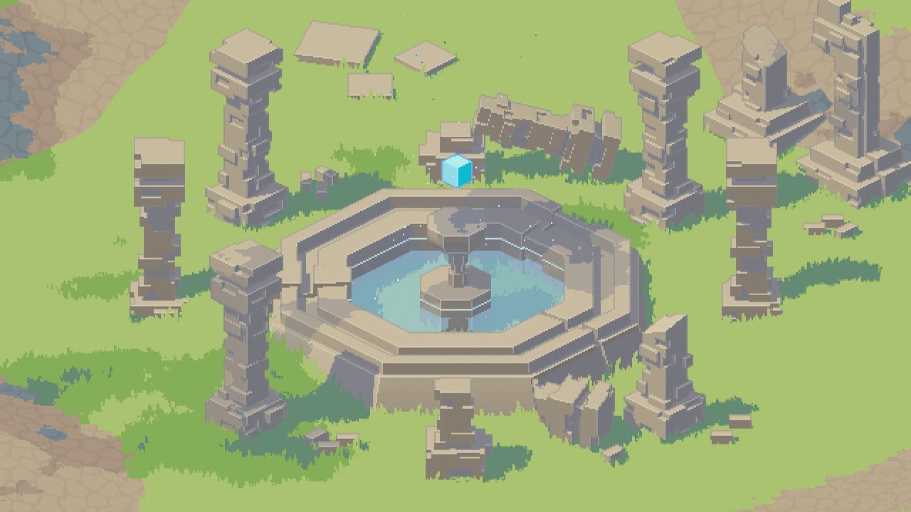
Date of Recording: 2020-11-02
Today I worked out a procedural day/night cycle system for my pixel art engine. The material colors are blended by interpolating between different variants of the materials for day, night, golden hour, and twilight depending on the angle of the sun. This gives the artist full control over the color palette for spec...
Basically not make it look as soft as seen
And another thing, would it be possible to add outlines and maybe make animations more choppier to deliver the hand crafted pixel art feel?
(Just to clarify, i have not made anything close to this in Unity. am asking to determine whether the effect i have in mind is possible or not, if that's not the case then i have to pick up pixel-art)
Anyone here with a little shader experience?
Having a problem and chatgpt cant help me. I wanna write a ComputeShader that detects if a pixel in the passed Texture2D (linear, Y-Flipped) is black or not. How the heck do i do this? Chatgpt only outputs crap... this is my current code:
// Each #kernel tells which function to compile; you can have many kernels
#pragma kernel CSMain

Texture2D<float4> _MainTex;
RWBuffer<int> _Output;  // 0 = transparent, 1 = blockiert

int _PixelX;
int _PixelY;

[numthreads(1, 1, 1)]
void CSMain(uint3 id : SV_DispatchThreadID) {
    float4 color = _MainTex.Load(int3(_PixelX, _PixelY, 0)); // Pixel-Farbe abrufen
    bool pixelIsBlack = all(color.xyz < float3(0.15, 0.15, 0.15));
    _Output[0] = pixelIsBlack ? 0 : 1; // Alpha-Wert prüfen
}
Which kinda works, but is wrong. I do not get desired results, probably because it does not know that the texture is y flipped and linear. Can anyone help me real quick? ^^
If the texture is Y flipped, simply invert the Y coordinate 🤷♂️
As for beeing in linear or gamma space, that's not an issue since black is (0,0,0) in both cases.
Hmm... and what about the linear input texture part? Is that an issue?
The thing is, when i run that shader the result is weird (its not even y-flipped). For example, i have a button at the bottom from the inpute texture. The shader does not flip yet, so i aspect to get a valid color at the opposite, the top. However thats not the case, the only space i get an valid result from is a tiny space on the left for some reason. So im not even sure if thats the problem.
hi, i'm recreating a vertex shader from another game, but i've had some trouble trying to figure out how to get this object to render through these individual wall and floor tiles

the tiles and the sprite use seperate layers, sprites are Transparent and tiles are Transparent-1
Under structure Varyings
Would it be any better to do
This: half fogFactor : HALF;
instead of This: half fogFactor : TEXCOORD0;
Just outta curiosity
So i have a compute shader reading an input texture to determine transparent/black parts. When the input location is black or transparent it should return 0. The input-texture is located on an canvas.
Thats the shader:
#pragma kernel CSMain

Texture2D<float4> _MainTex;
RWBuffer<int> _Output;  // 0 = transparent, 1 = blockiert

int _PixelX;
int _PixelY;
int _TextureHeight;

[numthreads(1, 1, 1)]
void CSMain(uint3 id : SV_DispatchThreadID) {

    // Y-Koordinate umkehren
    int flippedY = _TextureHeight - 1 - _PixelY;

    float4 color = _MainTex.Load(int3(_PixelX, flippedY, 0));
    bool pixelIsBlack = all(color.xyz < float3(0.15, 0.15, 0.15));
    _Output[0] = pixelIsBlack ? 0 : 1;
}
called like this:
RectTransform rectTransform = rawImage.rectTransform;
RectTransformUtility.ScreenPointToLocalPointInRectangle(rectTransform, screenPos, eventCamera, out var localPoint);

var rect = rawImage.rectTransform.rect;
var normalizedPos = new Vector2((localPoint.x - rect.x) / rect.width, (localPoint.y - rect.y) / rect.height);

int texX = Mathf.Clamp((int)(normalizedPos.x * texture.width), 0, texture.width - 1);
int texY = Mathf.Clamp((int)(normalizedPos.y * texture.height), 0, texture.height - 1);

// Prepare shader
int kernel = alphaCheckShader.FindKernel("CSMain");
alphaCheckShader.SetBuffer(kernel, "_Output", outputBuffer);
alphaCheckShader.SetTexture(kernel, "_MainTex", texture);
alphaCheckShader.SetInt("_PixelX", texX);
alphaCheckShader.SetInt("_PixelY", texY);
alphaCheckShader.SetInt("_TextureHeight", texture.height);

alphaCheckShader.Dispatch(kernel, 1, 1, 1);
outputBuffer.GetData(result);
However the shader or my calculation is wrong. See the attached image. It only detects black/transparent pixeels in the small red rectangle. All the other space it says its not blakc/transparent.
Why could this happen? Any ideas? Im stuck.

Thats the flipped input texture. My compute shader already flips the y-value

Any help appreciated, this drives me crazy
Shading I assume is just some mask so however you want to determine what each of those pixels represent, but you definitely can add a lot more shading depending how it's read. Outlines are easy (as far as simple depth testing goes) and there's many resources online. Animayion like wind is just manipulating vertices over some time/wave variable
Unless the sampled position is out of place, it doesn't make any sense that only the highlighted region returns black, when you can clearly see that it's different in the texture.
Thats the point. It does not make sense. But i dont know where the iusse is, something is messed up. Im pretty sure i calculate the coordinates correctly. I assume that in the input texture down left is 0,0 and upper right 1300x1300. And the position calculation looks correct... so whats going on here?
It shouldn't change anything, but just in case, what happens if you use texture = rawImage.mainTextre ?
Same weird result. I can not believe it, why isnt this shit working?
I'm out of ideas.
I did some tests. The input texture has the white area on top right? So i ran the computeshader with _PixelX = 100 and _PixelY = 1200 (since theres white). The compute shader returned that theres black. Looks like the damn compute shader does not do what it should, but why? I tested every corner, every combination like X 100, Y 1200, X 1200, Y 100 and it just returns black... some corner should be white in theory since the white label. But it is not
Can you maybe share the project ? I can give it a quick look, maybe I'll find what is happening
Hi. How come i can't connect a node to another in SG? This is for vertex position. If i recreate the nodes, it can connect all the way, but still can't let me connect to the final vertex position spot
Unfortunately Not, it has paid assets :/ Hmmm... There must be another way
It's probably because you are using a node somewhere in the chain that is only accessible by pixel shaders, such as DDXY or Sample 2D (instead Sample 2D LOD)
Hi people!
Do you know any way to rotate this geometry in 3D space?🤨

oh, you are right. but I was thinking there was some "trap" for fake it, because RGB could be "3 Axis".
Anyway I fake it!😁 👍 🙏

Hi all. I'm doing bottom path, but i thought the top path (using Transform node, Object to World) would be the same? They behave differently (the top path is incorrect billboard effect)
What's different?

How do I stop the black sphere from clipping through because they are both set to transparent surface

To be equivalent to the Transform node the matrix would have to be in the A port. (In the B port it acts like multiplying against the transpose of the matrix)
how can i write shaders to attach it to the camera?
So I have a series of textures (count can vary) that need to be applied in the same way with different values. Is there any way to just loop through all of these textures? I've seen some shaders that seem to have like, "expandable/addable" regions? Is that a custom editor thing?
can someone epxplain why my implementation of a normal map isnt working?

It still doesnt work even if I put both spaces to object
Does anyone have a repository of interesting normal map patterns? Something like this.

I just insert w/e fastnoise spews out at me
fastnoise?
Is there any way to get the Primitive ID in Shader Graph?
#if SHADOWS_SCREEN
float4 clipPos = TransformWorldToHClip(Position);
float4 shadowCoord = ComputeScreenPos(clipPos);
#else
float4 shadowCoord = TransformWorldToShadowCoord(Position);
#endif
Light light = GetMainLight(shadowCoord);
Color = CalculateCelShading(light, s);
int pixelLightCount = GetAdditionalLightsCount();
for (int i = 0; i < pixelLightCount; i++) {
light = GetAdditionalLight(i, Position, 1);
Color += CalculateCelShading(light, s);
}
#endif
}
somoeone can help
i tried to chane this script to work also with foward rendering but it doesnt work some expert ?'
hey i am very new to shaders but i want to make the ground brigde effect from tfp

can anyone guide me
Is there a premade hatching shader anywhere like this? Obviously the one in the picture but I can't find any place which actually provides it to be used.

I have a problem where the tilesets i'm making aren't connected, how can I fix it?

Hi all. I need advise on art asset management, specifically about UV sets, shaders, vertex color. For context, i'm doing the no texture, gradient atlas style

I'm just making a shader for sway. What's the common way to define sway-ness for a mesh?
I thought of making another UV set, and have the 0-1 in Y in the UV space to define how sway-y that vertex is
But should i use vertex color for this info?
What are the options of where i can store/author data in a mesh?
There's UV, and vert color. Anything else? Why are some things better suited for others, what examples, etc?
UV is a float4. So, is vertex color and UV the same thing, but edited differently?
https://discussions.unity.com/t/multiple-vertex-color-sets/784286/2
I guess this answers partly
I'm also wondering if, rather than relying 100% on painting the sway influence on vert color, maybe there should also be a programmatical way to define the sway influence. Like Y height, and/or XZ distance from origin
But could also be... vertex ID? I see SG has that node too
Hopefully there's a way to re-order vertex ID from a centerpoint pos, in blender
I'm figuring out what is "safe" to do, concerning batching/draw calls etc
I'm using URP. In this case i'm making a bamboo
I'm using GPU Instancer and considering if the unit of instance type should be a whole bamboo tree, or break it down to like 3: bamboo shoots, bamboo segments, bamboo mid leaf. Then with nested prefabs, assemble the variations in unity
Then i'd probably want the meshes in each prefab parts to register unto itself a bit of info of the whole tree's origin, for the shader to use for the sway
If i put this info to, maybe the 1st vertex of the mesh as a xyz (maybe in world space?), and do this register process in Awake, would this break mesh batching?
But it will not break material batching?
Perhaps making just a few variants of bamboo as single mesh (or, the parts have same origin point), is simpler for batching purpose?
// Get main light
Light light = GetMainLight(shadowCoord);
Color = CalculateCelShading(light, s);
// Additional lights loop (For Forward+)
#if USE_FORWARD_PLUS
  UNITY_LOOP for (uint i = 0; i < min(URP_FP_DIRECTIONAL_LIGHTS_COUNT, MAX_VISIBLE_LIGHTS); i++)
  {
      light = GetAdditionalLight(i, Position);
      Color += CalculateCelShading(light, s);
  }
#else
// Standard additional lights loop (for non-Forward+)
int pixelLightCount = GetAdditionalLightsCount();
for (uint i = 0; i < pixelLightCount; i++)
{
    light = GetAdditionalLight(i, Position);
    Color += CalculateCelShading(light, s);
}
#endif
#endif
}
why foweer plus doest work ??

this is the shader i have for shadow for sprite but issue is i got shadow but not actual sprite, how i get both sprite and shadow both.
this is shader
What render pipeline are you using ?
URP and HDRP don't support multi-pass shaders. (or more precisely, they don't draw all the passes simultaneously and need specific implementation for that)
@amber saffron Thanks for replay,I use URP. well i am not actually good at shaders and graphs. basically i want result like this.

Simple solution : Use two sprites ? 🤷♂️
Vertex color is stored per vertex, while what you have there is a gradient sampling technique based on UV mapping. You actually don't need to map your UVs out if you do just want to use vertex coloring, but the problem with that is usually you're limited in fine-detail as it's up the how populated your mesh is with them... which ideally you be dissolving as much as possible anyway.
You can also do like a half-half workflow where you've got a textures in places that need that fine detail like faces, then use vertex colors on the rest of the models - vertex colors to color fill then use textures to overlay the model.
Hi, guys! Have been using a shader from asset store for a while. Did not update anything including unity version and started to get this error during making a build: ’ maximum ps_5_0 sampler register index (16) exceeded ’. Why is it happening? I cant make only 1 build, than have this error untill i restart pc
// Get main light
Light light = GetMainLight(shadowCoord);
Color = CalculateCelShading(light, s);
// Additional lights loop (For Forward+)
#if USE_FORWARD_PLUS
  UNITY_LOOP for (uint i = 0; i < min(URP_FP_DIRECTIONAL_LIGHTS_COUNT, MAX_VISIBLE_LIGHTS); i++)
  {
      light = GetAdditionalLight(i, Position);
      Color += CalculateCelShading(light, s);
  }
#else
// Standard additional lights loop (for non-Forward+)
int pixelLightCount = GetAdditionalLightsCount();
for (uint i = 0; i < pixelLightCount; i++)
{
    light = GetAdditionalLight(i, Position);
    Color += CalculateCelShading(light, s);
}
#endif
#endif
}
Someone guys can help i dont know why foward plus part of my cell shading dosentt work??
Anyone has experience making custom shaders in ShaderGraph for Unity's canvas?
I have a UI effect that need some custom shader, but I want it to still be driven by Button & Image components Tint.
Getting the texture from Image from easy enough since it's just "_MainTex", but I can't find how the color variable is named.
Tried "_Tint", "_Color", "_TintColor", etc.
Im having some issues with the Overlay blend mode in my shader
I THINK the problem is that my input texture isnt in linear colorspace so the Overlay calculation is all wrong? But how do I save a photoshop png as linear color space?
If I pass in pure white I am expecting results like the left, but I am getting results like the right


is the problem that my texture isnt linear colorspace? How do I save a photoshop png as linear color space values? It needs to have the grey be EXACTLY 128 for this to work

I tried both of these implementations of overlay, but neither looks the same as it does in photoshop
Argh looks like all my problems were caused by colorspace conversion errors between linear and gamma
the results didnt look the same because I wanted gamma space overlay
Can anyone help with finding shilloute edges using a compute shader? I'm really lost. I can (sorta, had to rely on ai a bit for the code) find edges but for some reason I just can't get it working with finding the shilloute edges once the edges are found.
I feel like this might be quite difficult to achieve via a compute shader. I'd try to get it working on a CPU side on a single thread first. Then if it proves to be too slow, make it multithreaded, maybe using jobs. If the jobs are still slow, it should be possible to port it to a compute shader from there.
You're working on the volume shadows thing, right? Are you following a tutorial or something? Or what made you think it needs to be in a shader?
There aren't really any tutorials so I just kinda asked an AI how I should even try going about creating it.
There must be some resources online touching on it. I'd recommend looking them up first. AI can be quite unreliable with something as complex.
I mean I might just be bad at looking but for unity I can't really find anything. Closest I can find is an unfinished project on github and the wikipedia article for stencil shading/shadow volumes.
Are your talking about this project?
https://github.com/rhedgeco/UnityShadowVolumeGenerator?utm_source=perplexity
Yeah that one. It didn't work when I added it so I think it doesn't work with newer versions. And it also never worked with skinned meshed which are pretty important.
If was going to do it in a script how would I be able to tell if a side is lit or in shadow? Cast a ray from the vertex to the light source and see if there's anything in the way?
If it works at least somehow, you can use it as a base. Learn how it works and adjust it to work with skinned meshes.
I feel like casting rays per vertex would be very slow.
I'd recommend checking the GitHub repo and maybe some papers on the technique.
Hey guys, I'm having issues with Pixel Art shaders and upscaling textures. In my current project, I'm trying to create interactable foliage and a shader that gives my grass a way to "flow" in the wind. However, I'm having issues with how its being rendered.
I've attached an image of how the shader is rendering the foliage, it's very wavy and not pixel shaders at all. I am using this video's shaders and have no clue why this isnt' working right. I do have Pixel Perfect Camera on and its set to upscale render texture.
https://youtu.be/ecYWvfMoRIM?si=X0PudysgELvWi_G1

Still cant believe after all these years Shader Graph doesnt let you set Stencil operations
Actually, do you guys end up going the HLSL route with most of your shaders, or do you lean more towards graphing/shader node tools?
I have pretty much 100% transitioned to shadergraph and use custom function nodes for things not easily achieved with nodes
When block shaders come out we shall see
But right now the boilerplate for srp based shaders is too much
How would I make a shader that creates scrolling (in the y dir) diagonal lines


I need to be able to control their thickness as well
right now i have a strangely tiled line that has a slope of -1, while I want a slope of +1
maybe theres a way of filling in these "gaps?"

Maybe I should use a sine wave that is offset based on x?
And step the peaks ofc
Adding the UV R and G outputs together then Fraction (or Sine) -> Step should work
Optional Multiply with R/G outputs with -1 to flip directions
For other angles could use Rotate node on the UV instead and just one of the channel outputs
👍
got it working, thanks!

if I have one rgba value, how do I essentially overlay another rgba value over it?
Unsure of where to ask this, but how do I achieve this interaction circle in blender? I tried materials but it looks grainy 😦

I did it, looks good enough 🙂

Hi there! I’m experiencing an issue with the UGUI Shader Graph example. In the “Meters” tab, when I adjust the meter value, the circle progress shader doesn’t change at all. Also, the dial meter shader briefly transitions from opaque to transparent. What could be causing these problems?

Anyone know how to solve this, I’m still having this issue
Hello guys, I have an issue related to shader graph. I use multiple render pipelines in the Unity project due to assets I am using. And I cannot convert to URP. (Or HDRP)
Reason is that most of the materials and assets are old and I don't want to throw them away because of the Render Pipeline. (And the developer who maintains the package will not update assets to URP)
My problem is I wish to create a realistic water effect. (With Ripples, Reflections, etc.) I followed the tutorial and could manage to create a build in Shader Graph for water. It supports all of the features described. With one con problem.
It doesn't support transparency of the shader (in URP it supports it)
So, is there anyone who can help with setuping correctly nodes in the way it could support the alpha color of the shader? (So I could have more transparent water?
If you managed to make the shadergraph work with built-in, adding URP as target should yield very similar result.
Since you mention it is a water shader, you might need to enable depth/opaque texture in the URP asset though.
I do have included URP in the project. But the Graphics are build-in. Not URP. Simply adding URP Renderer (also converting all materials to URP) result to be everything pink in the project.
most of assets are pink
I would wish to remove "depth" I wish to just add alpha to the color
But I really stuck and don't know where to add the paramater of "color"
I could share the shader graph code if you need. I just literally don't know how to manage this stuff
Ok, I though that you wanted to have a shader ported from built-in to urp. But you want to stick to the built-in pipeline, right ?
WDYM by "just add alpha to the color" ? Isn't the alpha/opacity output of the graph what you want ?
It can help indeed.
I wish to convert from URP -> Build-in
My water looks like this:
It has features I need except "being see through"
I did manage to make a shader without all implemented features (just look like a water, but has no features of rippling, foam, etc.) (has ability to be see through)
You can see it in the second image


to the left you can spot a fish
(of the second image)
Sooo .... you have two shaders, individually with features that you want, but can't "combine" them ?
exactly
And what prevents/blocks you to do it ?
All I want basically is to grab "Ripple" system from picture 1, and add it to picture 2
lack of knowledge in shader programming
Oh, so left is the current shadergraph, right is a coded shader ?
Almost all HLSL/GLSL functions that you can read in shader code are available as nodes in shadergraph, so you "just" have to redo the same logic.
Alternatively, you can use a "custom function" node to copy/paste the shader code, but it might need some adaptations.
Opposite. Sorry for the confusion.
The right image is the shader I was following but I reached to the point where it wouldn't render the "see through"
I googled around and find out that I had to set it as "Transparent" not "Opaque" I set it and alpha variable appeared.
I controlled it using the Float value and it worked out.
I also managed to integrate (somewhat) correct system of Ripple. But it is pixilated. The shader on the left make it smooth. I wish to somehow just implement the smooth ripple effect to the shader on the right.
I am very sorry for confusion. My shader on the right just should be as is with only good feature of "smooth ripple"
RESOLVED
I'm working on a VR project and looking for a water package that delivers both high visual quality and strong performance under VR conditions, do you have any suggestions?
A bit old, but did you try this one ?

GitHub
Package repo containing the water system created for the URP Boat Attack demo project. - Unity-Technologies/boat-attack-water
Thanks, i will have a look at it
Resolved, this is not the solution.
I am having an issue with the Overlay blend more and Linear color space I am not sure how to resolve 


my goal: I am trying to do Overlay blend mode, but Overlay works as Multiply from >0.5 and Additive <0.5, Linear colorspace is messing it up
White works the eway I expect, but black doesn't
I am looking to get a result like the result in photoshop, but I am working in linear colorspace
I thought converting my greyscale to linear colorspace values would fix it, but that wasn't the case


I have tried with this both off and on, but it looks wrong in a different way for both settings
I THINK the problem is that Overlay works in ranges of 0 to 1, with 0.5 being critical, but linear and gamma color space's grey value at 0.5 is completely different
How to I fix it to work the way I want/expect though?
What color values does this texture have to be to get a result that looks like that for white/black but in Unity instead of photoshop?


ive done lots of experimenting and it seems like it just doesn't calculate colors above the 0.5 point correctly


this is just an ugly hack to try to take control of the values
added power on top of that 🫠 this lets me control the output look as much as I want, though I didnt want to have to do this much tweaking in post just to make it overlay right


I am hoping maybe there's just a parameter wrong in here that would solve all of this to make the brights behave nicer
Having trouble finding any sort of info on this so I figured I'd ask here...
Are their any alternatives in HLSL to a switch statement?
Reason I ask is because I have this dissolve shader I wrote yesterday which allows the end-user to specify what easing function to use for the dissolve effect duration via a property. I feel like this could be made more efficient without a switch statement but I'm not sure how. While it is clean, imo, shaders are all about performance after all. The shader works perfectly atm btw. This isn't a problem I'm bringing to light; more so just opening up for discussion into alternate methods for choosing what easing function to use while keeping it in the shader.
a powerful website for storing and sharing text and code snippets. completely free and open source.
I'm trying to create a wall shader that creates a hole in it, so you can always see the player, and as you can see of the first image it works. But I have the problem that even when the player is in front of the wall the hole is visible, how can I fix it? I thought to simply render the hole only when the wall covers even a little the player, but I don't know how can I do that. For context the effect is achieved by shooting for each pixel a ray and check if it intersects with a sphere which position is updated to the player coordinates


why do black colors get rendered as totally transparent regardless of the fragment shader alpha?


🤦♂️ never mind, it looks like particles are just getting rendered in front of this object
hello, how do i scroll these pixels?
i know how to scroll a noise with tiling node + time, but here I also need to create a pixelated version of the noise my uv node is occupied. so how can i scroll the noise?

What's wrong with tiling (offset rather) it before the noise
Hello, any idea why I can't plug the SampleTexture2D R channel in the Combine G channel? (it's grayed out)

hey I have a dumb shader noob question
so from googling it seems like you really can't apply multiple shaders to a single material
so does that mean in production code people's shaders are massive?
what i mean by that is, I have my terrain shader graph, it's got quite a few nodes just to handle coloring based on height and slope
if I now want to add some grass to that shader, it needs to be incorporated into that same shader?
just feel like it would get overwhelming trying to handle all that in one shader
Make one specifically for the vertex probably
can't really connect nodes between each other at different shader stages
For the most part, yeah. You're incorporating all the maps and blending together in one shader pass usually
For exceptions is stuff like outlines which you can do at the post-process stage
right, I've seen references to that
built-in actually was easier to kinda do multiple shader passes pretty easily, but URP kinda encourages you stuff it all together
wild, after these first few shader graphs I realized graph view isn't for me especially once it starts getting really complex so I've started learning HLSL
Unity's* HLSL is worse honestly. Unless you've some experience with GLSL/CG, you're going to be fighting against Unity's macro and libraries as you try to learn general shader coding.
but allows you to manipulate stuff like lighting/shadow and other features than what you can do in shader graph
I just tried that, it doesn't let me connect... In fact if I disconnect the combine, plug RGB, I can't plug the combine in Position anymore:

maybe textures aren't valid in vertex stage ?
To not cause XY problem, I'm trying to use a render texture R channel to define the height of vertices on a plane
There was a few others that work too I believe like the render texture one
Thank you very much, with the LOD version it's working 🙏
so i was following this tutorial on how to do procedural snow layers
it's kinda working on my terrain, but you can clearly see seams between my terrain mesh tiles

my hunch is that it's related to the snow noise part of my shader graph

is there a way to get it to sample the noise in world space?
Seems like either a UV issue or the noise texture that is not tileable
to fix the UV's you have to make the terrain corner starts at 0,0 and the opposite corner ends at 1,1 like so:

        private void CreateUVs()
        {
            int resVertices = _res + 1;
            var uvs = new Vector2[resVertices * resVertices];
            int i = 0;

            for (int z = 0; z < resVertices; z++)
                for (int x = 0; x < resVertices; x++)
                    uvs[i++] = new Vector2((float)x / _res, (float)z / _res);

            _meshFilter.mesh.uv = uvs;
        }
If you want to edit the shader instead, I think you can plug the Position.XZ node in the noises UV pin

I think there is no much to do here, the easeType value is constant on the material, so there won't be branching change per wavefront and performance should be good.
If you wanted to be sure to only evaluate a single option on the material the only other way is to use keywords and shader variants, but this will increase compilation time and break batches :/
But you can also approach it differently, since I see that the easing is for a constant progression accross the whole object :
Option 1: Move the calculation to the vertex shader, and store the result to an interpolator (ie. UV.z). Less work to do per pixel.
Option 2: Do the ease on CPU in c#, and pass the dissolveProgress value as a material property, as it is constant anyway.
Option 2 was my next immediate thought 
I just really wanted a way of containing all the easing in the shader since I'm making this shader (and a bunch of others) as a framework for other modders to use in RimWorld modding. So ideally they can just do <_EaseType>3</_EaseType> in XML to set which function to use and not have to worry about C# at all if they don't know the language and just want to use the shader for a cool effect.
Option 1 sounds like a pretty straight forward yet still nifty little trick. Can't believe I didn't think of that. Either way, like you said the performance is already fairly good and this isn't even going to be running concurrently for more than a few materials at any given time. RimWorld is simple in that regard, thankfully lol Thanks for the feedback though and pretty much confirming my suspicions about the switch!
One more thing, I'm trying not to just ping you right away too 😄 ... but, say the easeType is not constant and for some reason we update it for whatever reason during runtime via SetInt() or worse yet we do this continuously on a persistent material for some randomized visual pulsing where the easing function is different every _Duration; how would that affect performance?
It shouldn't have any noticeable effect, as it will still be constant over the whole object for that frame, and only one branch is evaluated.
Ah, makes sense. Thanks again!
Any legends out there with shaders want to help me brainstorm something?
I only know the basics for shaders but I have a concept for HDRP that i'd like to hash out and see if its possible or the best solution
its related to distance compaction and distance lod optimization. originally was going to use a matrix to warp/compress mesh but I figure it could be done better on the GPU at scale
I’d like to create a custom vertex color interpolation function to get the shapes in the attached image, or a rough approximation of them. I already know how to create the hard edge, but am looking for ideas on how to round out the otherwise sharp diagonal. So far I have tried leveraging the calculated vertex normals and face normals generated on the fly with limited success. I do get some curvy shapes with that method, but not very accurate.

I'm having a weird issue, i have a shader that allows fog and lighting to affect sprites but i also need z-depth within it and when i turn ZWrite on it creates an outline on some sprites that hides the fog behind the objects

Hi, what's the correct way to make a model with multiple UV sets, that can be used in shadergraph?
My model has "generate lightmap" on, and now the other UV set is just not found, no matter which UV set i use in SG
can somebody help me? i did this shader graph https://discussions.unity.com/t/highlight-intersection-shader/755202/10
but this only work when camera is outside object and i try to have this when camera is inside

Is there a reason you need to write to depth when you can just force the fog to the front?
I was playing around with this earlier in blender but apparently was having problems encoding multiple UVs. Instead I just imported two models and bumed the UVs off the other model
but if you do have the UVs, I believe you don't want to touch UV 1 (or was it UV2?) because unity uses lightmap data on those if you're baking it
hey all! I made a custom shader for experimenting, and when i assign textures to it, the top is fine; 3 of the sides are fine; and the bottom is fine; but one of the sides is upside down!
any fixes?

Open the cube up in* blender and flip UV of that side
it is a unity cube
that would have been what i would have done if i imported it but kind of new to unity so dont rly know what to do here 😅
@ebon basin sorry for ping but any ideas
Not entirely sure but I assume there's some logic you're missing to fix that case here unless Unity cube does have some bad UVs
if (absN.y >= absN.x && absN.y >= absN.z)
{
    texColor = (n.y > 0.0) ? grass : bottom;
}```
this is on urp
Really I'd just go make your own cube in blender and flip it and be done
yeah honestly atp i might as well
Im currently implementing blur to my UI and I can't believe there's no easy solution for this simple freature. So far it's working great blurring the background gameplay..
However I also need to blur UI elements behind the blurring panel. I'm using UGUI Screen Space Overlay canvas and I know that you can also use screen space camera but I'm really bound to Overlay couse many scripts rely on the UI scaling :/
Is there a way to access the canvas when the blurring panel gets rendered or another way (preferrably a shader that runs on the GPU and isn't too demanding as we're already struggeling to maintain performance) ?
Edit: using HDRP unity 6


Unity with "generate lightmap" in import settings will take (overwrite) UV1
So i put my UV to UV0 and UV2
The order of UV set in blender matters, which blender default can't conveniently do (had to use this https://github.com/ekaj2/uvmap_tools/blob/master/uv_map_tools.py)
i tried to make a shader with dither effect but mine has color but its supposed to not show the colors .is the problem with the shader graph itself or is it the renderer?


If I told you I had a shader that needed 14 textures, how would you look at me?
someone ever did glowing eyes on a 2D animated characters?
I've been trying for weeks! I get my character to glow, but when I add my emissive texture then it doesn't glow anymore...
that's about as far as I was able to get
Your screenshots aren't the sharpest but based on what I can see there you are never explicitly outputting a grayscale color for the final.
So, you need to either use a Saturate node or calculate the grayscale value directly by averaging the red, green, and blue channels and then connecting the result to the final color output.
is there a way to programmatically place shader nodes in shadergraph using c#?
i don't want to create shader, but i want programmatically place,connect,disconnect,and delete shader node
ahhhh I'm so close! the damned eyes turn white when I get close
Does anyone know how to edit a shader's code to make it work with terrain?
You don't. ;)
"Work with terrain" is an incredibly broad statement..
any ideas as to why my shader on an image is freaking out like this?
https://pastebin.com/epT5reks
Pastebin
Pastebin.com is the number one paste tool since 2002. Pastebin is a website where you can store text online for a set period of time.
This could be helpful as a reference. ChatGPT for shaders:

A fragment shader AI experiment by @14islands
That's actually pretty neat
in the doc it said i can define the scope of my shader keywordhttps://docs.unity3d.com/Packages/com.unity.shadergraph@17.2/manual/Keywords.html

but i didnt found such settings, Unity 6.0.31 URP

Are you on version 17.2.0 for shader graph though?
The version of Unity itself isn't the issue here
i am on 17.0.3

i mean, the image that they used both is the same

https://docs.unity3d.com/Manual/shader-keywords-scope-fundamentals.html
When you declare a set of keywords, you choose whether the keywords in the set have local or global scope. This determines whether you can override the state of this keyword at runtime using a global shader
keyword.
By default, you declare keywords with global scope. This means that you can override the state of this keyword at runtime using a global shader keyword. If you declare keywords with local scope, this means that you cannot override the state of this keyword at runtime using a global shader keyword. For more information and a code example, see Using shader keywords with C# scripts.
Note: If a keyword with the same name exists in a shader source file and its dependencies, the scope of the keyword in the source file overrides the scope in the dependencies. Dependencies comprise all Shaders that are included via the Fallback command, and Passes that are included via the UsePass command.
not sure if it's correct tho, probably didnt bother to update the doc
You still only showed documentation for one version prior 😄
That's...... not at all what I said or was even hinting at lol
You are on version 17.0.3 but you showed the docs for 17.0.4
Look at the 17.0.3 docs for starters to make sure you can do this in your version
here;s from 2021 - 2023


there's no way they decide to change only the 17.0.3 and then suddnely backtrack on the next version
That's not the point. Look at the docs for the version you are on for starters. That's what makes sense. Don't look at the docs for different versions if they don't apply to you. 
ok then how do i access my current vesion? clicking "documentation" on the package redirect me to 17.0.4 version

Hello, does anyone know how I could configure one material to reflect another? This is a vtuber/vrchat model, so I was trying with MToon and Poiyomi but I couldn't find a solution. I want the skin to reflect the shadow of the hair

"You can probably pack stuff"
"reflect the shadow" ?
that the hair can basically do this lol

Isn't it just regular shadows ? Like, does the light in the scene have shadows enabled ?

GitHub
⬜ Variable Ascii Effect for Unity Urp. Contribute to NullTale/AsciiFx development by creating an account on GitHub.
(just a good guy making good shaders)
thank you very much that works.is there any way to get the original color of the objects instead of everything being gray?
You could use a RenderTexture. Is this a full screen, post-processing shader you're making or what?
I'm trying to create a 3D texture to store a density value that I can sample inside a compute shader. I'm not sure if this is the proper way to do that
void InitDensityTexture()
{
  Texture3D tex = new(Size.x, Size.y, Size.z, TextureFormat.RFloat, false);

  float[] densityData = new float[_voxelData.Length];

  for(int i = 0; i < _voxelData.Length; i++)
  {
    densityData[i] = _voxelData[i].Density;
  }

  tex.SetPixelData(densityData, 0);
  tex.Apply();
  CS.SetTexture(0, "_DensityTexture", tex);
}```
this is going to be used like a volume public struct VoxelData
{
public int3 Position;
public float Density;
}```the purpose is to make something like this. Once i have the volume, I write vertices to a buffer, and those will sample the density at their position, which will be used for marching cubes

any ideas?
the zwrite is for the depth of field post processing not the fog itself
If you want depth of field then you probably want to just use opaque sprites with alpha clipping, then smooth the edges with post processing.
Unless there's some specific DOF post-processing for 2D I'm not aware of
To me, it seems the outline is the transparent quads that are writing to depth so you need a way around that
im just gonna do a work around and have a seperate camera for Background objects (a camera for main ground and foreground and seperate cameras for close background and for far background with different blur post processing on them)
I am using HDRP's built in water system along with my own buoyancy system and the issue is that if i put a large object onto the water it reacts too violently to the waves and i could just up the drag a ton but it wont feel how i want it to, is there some way to match some sort of sine wave to the waves to create a smoother wave (i am not at all good at shaders)
Sorry if this is a stupid question, but how can I pixelate the fresnel effect using my pixel-ify setup? (I haven't used unity in forever)

Why does this not actually result in ints in the inspector?


Like I know they're floats under the hood.
If you create a compute shader to handle some effects, you need to manually pass in the projection matrices right? So like for example in a surface shader unity_matrix_i_p is automatically set but in a compute shader i assume you need to make a variable for it and pass it from the c# side where you dispatch it?
so i see, decal dosent always update and theres no option for that to enable
is it possible to make it always update and render?
You typically don't use compute shaders to render objects, so you don't need need to pass in any matrices(there's nothing to transform with the said matrices).
And while we're at that postprocessing effects usually don't use compute shaders either.
I'm not sure if this is the right channel for this. I'm guessing it's shader related. I have a spell that spawns a prafab under the players transform. As shown in the video, the prefab clips through the floor if on any elevation. Is there a shader or something that can make it follow along the terrain? I hope that makes sense
https://github.com/GarrettGunnell/Pixel-Sorting
example of using compute shader for post processing
GitHub
A "real time" pixel sorter for Unity. Contribute to GarrettGunnell/Pixel-Sorting development by creating an account on GitHub.
Thanks. I'll look into that once I've finished what I'm doing
I'm trying to implement beard customization, created seperate transparent texture that matches the same uv map and only has beard, blended them together like this and it works. However beard texture has a lot of empty spaces specially for other body parts. What can I do here?

Do you need a full texture for the beard ?
If the base texture doesn't need alpha, you can use the base alpha channel for the beard mask, and color property for the beard.
No it doesn't. I added base texture, created another layer for beard and painted, then exported the beard. This way when I blend it goes where it belongs. Idk if that makes sense sorry.
I dont think base needs alpha at the moment so I can use that, do you mind explaining a bit more about the beard mask? Also would using the base alpha work with multiple customization parts like eyes and beard etc. together?
Right now you are using a dedicated beard texture to overlay it over the base, with the lerp node.
The T input of the lerp is the "mask", and you are using the beard alpha channel for that.
My suggestion was to store that mask in the base alpha, and use a constant color property for the beard instead.
But as you mentioned, it won't work with more customization parts.
Ah, gotcha. Yeah that wouldn't work then...
I would approach this in two different ways, first off do a raycast to place the pivot of the object on the ground, but for the texture part of it use a decal, which can adapt to terrain height
Basically, to make this work, for each part you need to lerp between the previous "layer" (starting with the base color) and the part color, by the part mask.
If done naively, this mean you need an individual texture for each customizable part.
But of course it can be done in better ways 🙂
Here is my suggestion, it needs some image editing skills but shouldn't be that hard :
In a single texture, use 3 channels to store 3 different informations for the customization :
Red : the ID of the part that is customized.
Green : the mask
Blue : a greyscale "light/shadow" for the part that can be applied as overlay blend to add details.
Then in the shader you replace each ID value by the matching color, overlay the light/shadow and blend with the basemap with the mask.
I'll give it a go in an hour or so.
That's gonna take some time 😄 Let me see how it goes thank you so much
I'm even ok with keep lerping for each part but what can I do about the empty part for beard for example? If I create a 32x32 beard and lerp it it wouldn't position itself to where it supposed to go
No, indeed, but you can user the texture scale/offset to move it at the proper space in the map.
Here's a very rough example of what I was talking about

not sure if you using SRP or not, in SRP you can change the render order of terrain, player and particle using render feature, which mean i can change the render order of terrain to be below of particle, this will eliminate the possibility of particle get obstructed by terrain but alos make sure that the particle doesnt render on top of player
in BIRP i think you can use stencil to make this work
not sure with the setup tho
I'm on URP. I can't see this being a complex fix as it seems like most games would have something like this. Almost done what I'm doing then I'll get to it ^^
some game that wont render player would just turn the ZTest to always, but if you have hand or weapon and dont want the particle to be render on top of it then i think using render feature would be the best way to do it
or use camera stacking, that could work as well
Ok. I'm here to tackle this now :p
I found this. https://discussions.unity.com/t/draw-on-top-of-floor-and-behind-objects/739717/2 I beleive the option 3 is what I'm looking for. I am a huge noob when it comes to shaders so I'll have to try and figure this out as it's all foreign language to me :p
tbh stencil is hard to impelement bcs :
1.shadergraph doesnt have stencil
2.unity build in particle shader doesnt have stencil
3.you can inject stencil via render feature but's it's confusing
but that's just my opinion
except point 1 and 2, those are fact Laugh2

brrrr. I tried changing the height of the spawned prefab relative to the terrains height... It was awful. I want the circle shown in the video to bend with the terrain. so if there's a slop and im on the edge of it (on the flat area) it'll be flat where i am then bend up the slop. meh
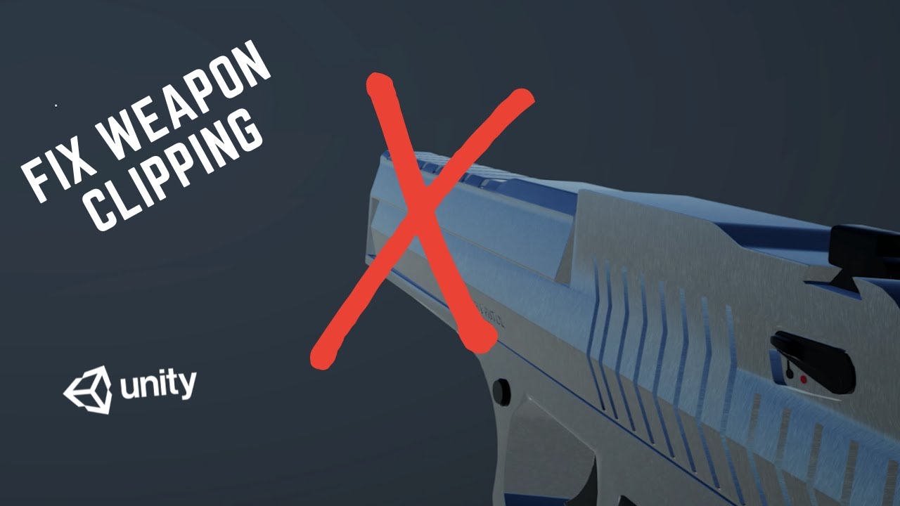
I was messing around with this little FPS that I have apparently started writing - and I came across a clipping issue, whereby walking into an object causes half the weapon to disappear. So I wanted to see how to the Unity team solved this issue, and having a look at Unities FPS Microgame it seems they took the approach I explained in the video....
if you are beginner to render feature and shader, i think camera stacking should be the easiest way to do
I'll do this quickly and see how that goes. I'll send an update shortly
It's way better
Thank you. Learned something new so that's sick ^^
another way you can make the "area" effect as decal, and only use camera stack for the particle that flaying around, but yeah, you will need to fix the decal when it's near terrain that very steep, anyway congrats, happy learning Thumbglass

I'll keep as is for now. But I've screenshotted this and added it to my to-do ^^ Thank you
very inexperienced with shaders... but how can I accomplish this? and 2nd... would this degrade performance or no?


Left Photo = Current Shader | Right Photo = How it looks rn
basically I want it so the sides and the back of the camera would dissolve the object... but the front view would keep it solid at all times
Yeah, i would like to experiment with compute shaders for SRR. i found an old github repository also using a compute shader instead of a surface shader. I think in this case it could work. it's mostly to see what would be more peformant
How are much are you guys willing to pay for a addon that makes it easy to bake texture in blender and automatically map those texture to any material
Hi! I'm a beginner to shader graph but I need to make an animated gradient background for a proyect. Can someone guide me on how I could achieve this?
Alright this is going to sound insane cause I think I'm going crazy.
I have 2 textures.
They have semi-transparent regions.
How do I alpha blend them normally in shader graph?
And by alpha blend I mean imagine these 2 textures/sprites were just on top of each other in the scene view.
I think it would only be possible by using Scene Color node (& 2 lerps)
Oh I don't actually need to blend with the stuff currently in the scene. I just have 2 textures with semi-transparent regions. It seems that default blend behaviour is Source Over. Is there no node to replicate the default behaviour?
I mean the blending order is important so in order to get the same result as 2 semi-transparent overlapping sprites you need the initial color afaik
Any chance of using arrays in shader graph?
Only in custom function nodes, see https://www.cyanilux.com/faq/#sg-arrays
Might be easier to stick to Texture2D
hello, if I need to process an array of input in a compute shader, would it be better to iterate on the cpu or pass it as a buffer array and do it in the shader?
Is there anything wrong with doing this?

doesn't Unity have a blend node already?
It does but none of the modes seem to have the standard blend behaviour >_>
ohhh didn't knew that, sorry to hear that lol
how do you guys even do shockwave on ground 😔
look up distortion shaders. Basically just taking previous frame data, distorting it, then rendering at current frame
They should. You can specifically make decal shaders
can anyone guide me on how to remake this shader in unity? i did the model + blade shader in blender before I realized the shader graph from blender is not importable to unity.. 😭

Similar idea with shader graph, instead of a mapping node you're using a tiling and offset node with some time constraint to scroll the UVs, then your choice of a texture/noise
❤️
I use urp and shader graph to implement a custom sprite shader. My sprites are packed in some atlases. It seems I need to handle sprite uv adjustment manually in the shader, right?
So, I should pass the sprite origin/offset and the size in the atlas?
idk where to post this but this channel seems right,so i made a room in blender and imported on unity and this wall was affected by face culling and was invisible,i made a work around by creating a material variant cause i couldnt change the variables in the shader component and it ended up like this how can i disable face culling without making the wall look like that?

Is there a way to stop a shader graph shader from receiving reflections from probes? it's water with custom planar reflection / URP
Might be able to define a boolean keyword with reference _ENVIRONMENTREFLECTIONS_OFF as it's used by the shaderlibrary iirc
https://youtu.be/-07OX-gNarc?si=d1QBK0V51FXKe36D Does anyone know some tricks to achieve a similar visual style to the game "Antichamber" ? It has extremely "flat" graphics with almost hand-drawn style outlines on the models. Is it done with shaders or what?

A full no commentary playthrough of Antichamber
Game: Antichamber
Release Date: January 31, 2013
Platform: PC
Developer: Demruth
Antichamber is a first-person puzzle-platform game created by Australian developer Alexander "Demruth" Bruce. Many of the puzzles are based on phenomena that occur within impossible objects created by the game engine...
I'm sure I'm missing something really simple here, but I am trying to write my own frac() implementation to allow for offsetting, and for some reason input - floor(input) is giving me very different results from frac(input).
Outline shaders
would be an unlit shader + outline shader

how come the offset of my uv is affecting my tiling on my tilemap.
I am pretty new to writing shaders, but I was wondering if there is a way to apply one to the entire scene and modify every vertex on the GPU? Possibly as a post processing layer. I have seen this done in Minecraft, warping the world like in Inception, but it’s possible the whole game world uses a single shader. Not sure.
It's likely all/most objects in Minecraft use the same shader.
It's not possible to affect all the vertices of all the objects in a post processing shader.
In fact, it's not possible to affect vertices of any object in a pp shader.
Hi all. I'm using the Object node in shadergraph, mainly the Bounds size. But the value seems to change based on the camera distance, between the correct ( i guess?) value and a very high value. In the scene view, the value changes between these 2 in an interval. In game, it seems only between distance of 3-4 from object root does this, and any other distance outside of 3-4 is fine
Anything i'm misunderstanding here? Is it LOD related?
Could be related to batching (combining objects/renderers into one draw call)
(specifically static or dynamic batching - not srp batching)
I'm making a custom pass for hdrp, does anyone know how the ScriptableRenderContext.CreateUIOverlayRendererList() method works?
Im using the DrawRendererList (line 96) to draw the overlay ui to a custom buffer, which works, but is there a way to only draw specific UI overlay elements (CreateUIOverlayRendererList draws the entire UI into the buffer)?

Is there anything i can do then? I want this value to be per mesh, not per material that i have to make a variable for it
It's not SRP batching. Apparently on mine it's already off
If it's on, my mesh is always with that high value in every distance, actually
Oh wait maybe that's the other way around
The high value is the correct value
The correct solution would be to have normals pointing into the room, or duplicate the faces if you need normals in both ways (preferably give the walls some thickness too)
Disabling culling doesn't change the normals, so the lighting is calculated with negative normals
Though it's mostly visible with environment reflections, disabling them isn't a true fix because other parts of the lighting calculation are affected as well
tnx
Hi guys, I'm trying to phade in/out a previous room in my isometric game, my approach consists of using a second camera that uses layer culling to render the previous room, render it to a renderTexture and then with a shader post process it on top of the main camera using OnRenderImage , it works but this approch does not respect the depth buffer, so my second camera overwrites the main camera and viceversa. How can I fix it so that the depth culling is handled properly? Do I get somehow the second camera depth buffer and pass it to the main camera post process shader or there is a better way
fixed4 frag (v2f i) : SV_Target {
    return float4(1, 0, i.uv.x, 1);
}```Can someone please explain why in my hlsl shader the color is only being outputed as red and not a gradient as it should be?Are you setting the uv in the vertex function?
v2f vert (appdata v) {
                v2f o;
                o.vertex = UnityObjectToClipPos(v.vertex);
                o.uv = TRANSFORM_TEX(v.uv, _MainTex);

                return o;
}```I mean I guess I don't know much but i'm pretty sure here unity does it for me on defaultI'm pretty sure this line set's it no?c# o.uv = TRANSFORM_TEX(v.uv, _MainTex);
Sure, using tiling from texture. Maybe that's set to 0,0 on material? Would also want to make sure the mesh is UV mapped
Shader "Unlit/WaterShader" {
    Properties {

    }

    SubShader {
        Tags { "RenderType"="Opaque" }
        LOD 100

        Pass {
            CGPROGRAM
            #pragma vertex vert
            #pragma fragment frag

            #include "UnityCG.cginc"

            struct appdata {
                float4 vertex : POSITION;
                float2 uv : TEXCOORD0;
            };

            struct v2f {
                float2 uv : TEXCOORD0;
                float4 vertex : SV_POSITION;
            };

            sampler2D _MainTex;
            float4 _MainTex_ST;

            v2f vert (appdata v) {
                v2f o;
                o.vertex = UnityObjectToClipPos(v.vertex);
                o.uv = TRANSFORM_TEX(v.uv, _MainTex);

                return o;
            }

            fixed4 frag (v2f i) : SV_Target {
                return float4(1, 0, i.uv.x, 1);
            }
            ENDCG
        }
    }
}
```Here's the full shaderi think i'm not doing anything w the texture at all
Then that's likely the problem, remove the texture and TRANSFORM_TEX (just o.uv = v.uv;), or add the texture property back at least (so _MainTex_ST can be set correctly)
Ok I will try just removing it then
fixed4 frag (v2f i) : SV_Target {
    float target = cos((i.uv.x + _Time.y) * 25);

    return target;
}``` Why does it move at like 0.1fpsif i multiply the time value no matter how it will still have a gross and choppy framerate
enable "always refresh" in top right of scene view

in the second image I moved the first floor to the bottom but still overwrites the original camera


I used this to render the second camera renderTexture to the main camera```cs
//main Camera
void OnRenderImage(RenderTexture source, RenderTexture destination)
{
this.UpdateTexture();
Graphics.Blit(source, destination);
// Then draw the overlay with alpha
if (this.material != null)
Graphics.Blit(this.renderTexture, destination, this.material);
}``` Should I somehow get the second camera depth buffer and manually compare depths in the shader or is there a better approach
I want to have a starry sky skybox, I’m currently using a cubemap but would love a way to get it crisp without very high resolution image (it’s for mobile). Are there any performant ways?
I dunno something like a noisemap multiplied by view angle and just taking peaks or something….
Oh wow thank you lol
I was having a lot of issues
is there a reason it's not like that on default
Probably to improve editor performance
i was editing a shader graph and for some reason the preview isnt showing anything, just a transparent sphere. some of the nodes look weird as well. but the material i made out of it looks fine. i tried restarting unity but the preview and nodes still dont show properly. how do i fix this?


Likely need to change the "default value" for the Thickness property (under node settings tab while property is selected)
wtf
your a genius 😭
thank you
cant believe i didnt realise that
wtf
so you just looked at those pics
and understood what the shader was doing in like 30 seconds
Kinda yea, mostly from the result in inspector and since it's named Grid
🤣 fair enough
and yes i know i couldve probably just used the sample grid they gave and just modified it a bit
but this is my first time and i thougt it would be interesting to try it myself
Let's say I have a sprite sheet texture that's broken up into many frames. I want to tint each frame of the sprite using a gradient across its Y axis.
When I use the UVs in shader graph, the UV values change since we're moving through the sprites on the texture.
So how do I do this? Any tips?
using the urp, however when importing urp materials they show up as pink for some reason

and i know the project is correctly made as URP, as when given the offer to change material shaders, it offers to change them TO URP
nevermind i fixed it turns out i replaced the URP asset by accident which unsynced the two
it looks like canvas render targets got added to urp in 16.... is it not possible then to do this kinda thing even on a world space canvas in 2022?
I'm particularly wanting to use it on something that uses the radial 360 mode with fill
Unlit graph might work for worldspace UI, it just doesn't for overlay as that tries to render all shader passes
For reference this is how I am calculating normals. I tried adjusting the offset, but it doesn't seem to be related to the banding:
    float2 e = float2(1e-2, 0);

    float3 n = GetDist(p) - float3(
        GetDist(p - e.xyy),
        GetDist(p - e.yxy),
        GetDist(p - e.yyx)
    );

    return normalize(n);
}```hmm so ok interesting it is kinda working. However, I want it to utilise the fill amount, which is set in image....
