#archived-shaders
1 messages · Page 99 of 1
 Would probably need a lot of rewrites then I suppose. Rip. Any idea what the pattern is called?
Halftone
Oh it's just called halftone? I thought the pattern would have some fancy mathematical name.
It originates from old physical printing techniques
Yeah halftone shaded comics are the style I'm trying to emulate for my game, I just didn't think the pattern in code would be called that lol
A halftone image filter probably benefits from math, but there's many ways to go about it
Does this need to be able to cover up any object, or is it just going to be on a specific object?
I saw a video recently about doing this sort of thing...
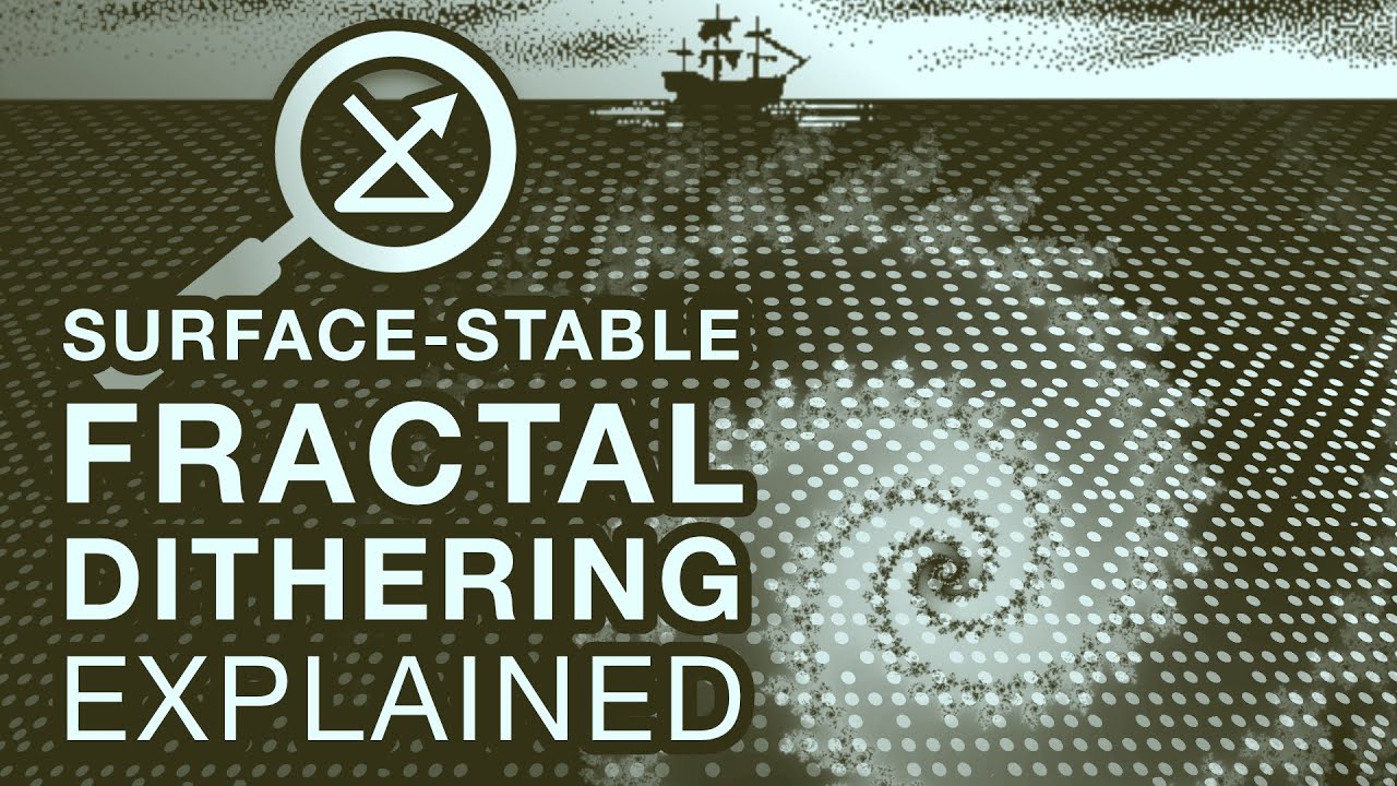
I invented a new form of dithering I call Surface-Stable Fractal Dithering. I've released it as open source along with this explainer video of how it works.
Also see my demo video showing a variety of styles, including in color:
https://www.youtube.com/watch?v=EzjWBmhO_1E
Find the shader source and example project here:
https://github.com/rune...
It creates a halftone-styled effect
(although it's not exactly a halftone)
i'm gonna try implementing this soon; i want to create a VRChat avatar with an Obra Dinn-style gimmick
Yeah I used that video when making the bayer version of my shading.
ha
If I had to do this Right Now (tm), I would try calculating the average brightness of each pixel in square bins
Heya all, first time really digging into shaders here.
I am looking to displace a tree more and more the further up from its origin/pivot, in Shader Graph.
The logic of it is.. working but I am getting a really odd disconnect between what is being rendered and what.. Seemingly 'should' be rendered? Any advice? Pardon if this isn't the best place to ask :/

The outline you see in the scene view can become disconnected from the rendered mesh
although I am surprised by that outcome a bit
First time I've come across that, felt spooky.
 Thanks, this looks a lot better than it did before. Doesn't have the bayer + pattern anymore yay!

Is this being rendered by a terrain renderer?
Like I was doing things I was not meant to be doing
or is it just a mesh renderer?
Mesh renderer in a manually placed prefab
Exhibits the same behaviour when viewed inside the prefab :S
Is that a single mesh or two?
Where IS the pivot?
I'm not sure I understand if honest, I'm not using anything in regards to the Depth buffer (as far as I am aware), this is literally just applying an image to the albedo channel but making the material Transparent. I've done the same thing with other objects in my scene, but this is the only model that I have this issue with. It's very odd. lol.
I love trying to work with shadow volumes they aren't a torturous endeavour at all! 

One of a few different objects, maybe up to a dozen, and they're all 2d sprites.
A single mesh, two material slots. Pivot in the bottom of the tree, but may not be exactly at the absolute lowest point.
In the 2d light system is there any way to achieve fex specular highlights using a spec map and normal map? From what I can gather normal maps fex is handled by another system outside of the custom lit shader graph? I see no way of getting the light direction of closest light fex
Something like this ?I've found that the following blend modes matched what you showed : "Linear Light Add Sub", "Overlay", "Soft Light" :


@snow depot Don't post off-topic images here, please. Read #📖┃code-of-conduct
It was on topic I'm complaining about how hard coding a shader is
The dude in the picture was the guy who invented shadow volumes
If you have constructive suggestions use Unity Discussions for that.
Does anyone know how I can make the forwards lit pass render both areas within and outside a stencil buffer value, but the way they're rendered is different based on if it is or isn't in the buffer value? I can only manage to make it so everything outside the buffer value is completely excluded from rendering. I'd like it to be that when part of the shader is in stencil shadows defined by this buffer it sets the texture to black. But everywhere else it displays the normal texture.
Stencil
{
Ref 0
Comp Greater // Render where stencil > 0
Pass Keep
ZFail Keep
}
You'd need two different passes
Can't you only have one forwards lit pass? And isn't the forwards lit pass the only one which can render things? Or am I misunderstanding something?
I guess this depends on render pipeline. Are you using the built-in render pipeline here?
i'm most familiar with that when it comes to hand-written shaders
I'm using URP
a quick test suggests that this is fine. I have a shader that does a sort of "deferred rendering" of an effect -- I stencil many small areas, then run a single pass to fill them in later on
Pass
{
    Tags
    {
        "LightMode" = "ForwardBase"
    }
    Stencil
    {
        Ref 32
        ReadMask 32
        Comp Equal
    }

    Cull Back
    CGPROGRAM
    #pragma multi_compile _ SHADOWS_SCREEN SHADOWS_DEPTH
    #define PASS_FORWARD_BASE
    #define RIME_STENCIL
    #include "rime-pass-main.cginc"
    #undef PASS_FORWARD_BASE
    ENDCG
}
It looks like this. I copied it and set the stencil to NotEqual, and it now draws everywhere
Typically, you get one ForwardBase pass, then many ForwardAdd passes
But I think what actually happens is:
- Every ForwardBase pass runs once
- Every ForwardAdd pass runs once per additional light
Wait does that mean forward base needs a directional light?
Well I guess if it does I can just have base not render anything and all the textures are rendered via forward add.
Thanks!
I haven't actually checked if a non-directional light can be supplied in the base pass
anyone has a video on how raycasting and basic shadows work?
those are two very different topics!
were you thinking of raymarching, maybe?
well -- I suppose they're the same topic if you're writing a raytraced renderer
Fingers crossed since my game relies heavily on point and spot lights. But I can't really test it out now since my shadow volumes are broken. 
hi guys i was a month into this project and it displayed this after a lightbake
plz help 😭


Can anybody help me out with this? The shadows kinda work now if you squint your eyes and look at it from the right angle but the actual object casting them is invisible and I can't figure out how to fix it. It's supposed to work with the Carmack's Reverse method.

A tool for sharing your source code with the world!
quick question is there any docs for URP HLSL cause i cant find them
do they js want u to read the shaderlibrary sourcecode from the package to understand how to write them
like docs for all the library functions like how to calculate fog and ambient lighting cause thats what im tryna find rn since its not in any tutorials
having issue with a screen shader, it duplicates the view in your eyes in VR in Unity 2019, resulting in this:
(view from 1 eye)

i dont have much experience with shaders at all so im not sure what to do about this
its for beat saber 1.29.1, which uses single pass stereo, it works fine on newer versions of the game which use single pass instanced
wait i think i fixed it
o wait i think that might be it
ty
i think i saw that before i js thought i was missing something since it has very little written there
I have a 3d crosshair which is raycast onto where I'm shooting. I want this to be rendered above objects on certain layers (terrain, enemy etc) due to colliders tha tmight not align perfectly and wanting to still see the crosshair. I can't think how to do this, any ideas? I am in a cockpit that should be able to occlude this crosshair object, so it still needs some kind of z testing
Tried to use a decal ?
hmm, I hadn't considered this - is this performant on mobile vr? (probably not?)
but also, I think this might be visually confusing
Hum, since you want it on certain layer but not all, you would also need to enable decal layers, and this might take some additional memory ...
Else you could try a custom solution based on renderer features and stencil mask
thanks. I assume there's pretty much always a performance hit from those latter options too?
A vertex shader that ensures the crosshair is always a certain distance from the camera could be a simple solution
But a stencil renderer feature you could use for any number of other HUD elements too
Well, you need to have an additional draw call to write the stencil mask, and on other one for the decal.
But the first can be done with a very simple shader (almost empty vertex frag, only writing to stencil), and the second you need to come up with a decal shader yourself (a very simple box projection).
draw call I don't mind, but I assume the performance of writing a full screen stencil and using it could be significant? (I'm on oculus quest, and for example can use no post processing effects as they cause another render). I haven't done stencil stuff before so could be totally wrong
The stencil already exsists in the camera depth buffer, so you won't add more memory. With the render object renderer feature you are just writing onto specific free bits of the stencil for the mask, and it's not really fullscreen as only pixel where the objects are drawn are written into.
You could also profit of the existing depth buffer in the stencil write shader to do Z-Test Equal
would that rely on this? as I have this off for performance also

No, this is a copy of the depth buffer to make it accessible in shadergraph, not the actual camera depth.
ok, cool. Thanks for this info. I'll look into stencils and render features, it would be useful for a growing set of hud elements
and I'd guess I could use this still in shadergraph somehow, custom nodes or whatever
The shader for masking would probably better to so with shaderlab, but the decal can be done with shadergraph ....
Oh wait, crap, the decal does need access to depth :/
I feel decal is probably the wrong way to go for the effect I want
although literally every shader in my game goes through shadergraph for some universal functionality
Maybe I misinterpretted what you want, you said display on terrain so I though of projecting onto the terrain shape, but if you just want some "flat" UI masked by some objects, a regular mesh/UI that displays only over the stencil mask is enough, and no need for the additional depth texture.
I just want to be able to render a sphere on top of everything except certain things.... like my cockpit interior
Should work then
Not entirely sure but from what I see so far is that using any renderer feature causes another blit, which I can't allow. Will continue looking
Does the Depth Scene node work with WebGL? After calculating the orthographic depth and plugging it into color, I'm just getting solid white
a quad that acts as the crosshair plane, and you calculate crosshair's uv offset based on the projection of the raycast to the crosshair plane. no need for complicated shader setup, but it might take a few trials and error to find the right equation though. and this makes it more like programming question than shader
so another issue is that as I'm in stereo VR, I want the percieved depth in terms of stereo separation to be the same as the surface it's on
Ive got a custom shader, its based on urp lit. it has some conditional logic, and basically I want to modify the alpha and shadow accordingly. in the forward pass if I set the alpha to 0, obviously the pixels wont be visible, but a shadow is still rendered. if I use a texture with an alpha(like say a tree foliage texture with alpha), both the pixels and shadow are properly modified. what am I missing in regards to the shadow portion of things?
The shadow pass can't be half transparent, but you can use alpha clip (with clip or discard hlsl function) to not draw pixels in the shadowmap.
thanks for pointing me in the right direction, ugh using the same conditional logic from my forward pass inside doesnt trigger the clipping
Can you show a bit how it's done ?
sure:
this is the last part of the vertex shader for both forward and shadow passes
#ifdef UNITY_DOTS_INSTANCING_ENABLED
#ifdef VERTEXCOLORS_ON
    // _VertexColorIndex is the instance
    output.vertexColor = _VertexColors[asuint(unity_DOTS_Sampled_VertexColorIndex) + input.vertexID];
#endif
#endif
    return output;
using the same #ifdefs at the end of the fragment passes(i was just using discard, tbh not sure the minutiae with each but it works inside of forward)
// sameifdefs
    if (input.vertexColor.a < 0.5)
    {
        color.a = 0;
        clip(color.a - _Cutoff);
        //discard;
    }
the bottom snippet is literally right before setting outColor = color in forward, and return 0; in shadowcaster
oh and in shadowcaster fragment its
clip(-1);
obviously just setting clip(-1); outside of the ifdefs in the shadowcaster frag just kills all the shadows so at least that is working
but the buffer being sampled is the same
ahhh was missing the shader keyword declaration #pragma shader_feature_local _ VERTEXCOLORS_ON in the shadowcaster pass 😌
Apparently linear depth is just flat out wrong with the scene depth node.
Surprisingly, works fine with WebGPU /shrug
Actually only seems to be a problem for orthographic though? I'm confused. Must be some flag that's not fliping when using WebGL2
can anyone explain this piece

Here the dude is computing o.positionSS which is basically the screen space positions of the co-ordinates
and in the fragment function near the end, he just took the xy position of the computed co-ordinates divided it by w and called it screenspace UVs
how does that work
I mentioned this to you the other day #archived-shaders message
ComputeScreenPos actually just remaps clipPos (-w, w) into a (0, w) range. You divide by w to put it into a 0-1 range. That has to be done in the fragment stage to produce correct results afaik
thats fine but how does it become UV coords
bro put it in tex2D
which is wild
UV is just the usual name used for coordinates that are going to be used for texture sampling
oh wait, is the dude taking the current screen position of the object to sample the texture onto?
that makes sense
Screen position of the vertices/fragments, not the object's origin. But yeah, the result is projecting the texture onto the object in screen space
I could use a billboarded quad but for a 3d sphere, what type of input (position, view direction, normal, other) will give me a consistent -1 to +1 xy "UV" on a 3d sphere no matter what angle I look at it from?

I tried various inputs but I couldnt get a surface that was always a -1 to +1 XY UV from all view angles

2.*vec2(dot(camera up, position - object position), dot(camera right, position - object position)) should work methinks?
How do I get Camera's up and right from within shadergraph?

I think a direction is I take direction and multiply it by a vector pointing the direction I want? 
not this

I think you could use a Transform (direction) node and transform from view space to world space?
Alternatively you can pick an orientation vector v (any vector!); so long as the camera direction isn't parallel to v, you can get "up" (a) and "right" (b) as a=normalize(v-camera direction*dot(v, camera direction)) and b=normalize(cross(camera direction, a))
(if camera direction is parallel to v, the thing inside the first normalize becomes zero and it returns divide by zero error)
uhoh
btw I meant transform up (0,1,0) and right (1,0,0) from view space to world space
I am surprised by how nontrivial it is to return a sphere looking like this 👀

this isnt your code working yet, this is just it centered in view, im still trying to program what you said
yea, seems to work that way the wording confused me
with this, the orientation vector projected onto the screen will be the y direction for your UVs, if that works for your case. If the camera has arbitrary orientations but you always want the UVs oriented a specific way in screen space, this won't be good

Im trying to map this distortion quad to be a distortion sphere
I could just billboard the quad but I don't want to do that, I wanted to see if it would work on a sphere
I wasnt intending to texturemap the -1 to +1 uv space, if that changes things

Fresnel gives me the right radii, but its not pushing the correct directions without some kind of adjustment there
pictured is the UV -based version
I think this does need the same orientation in screen-space, so go with the first one (Transform (direction) Vector3.up and Vector3.right from view space to world space and that should give camera up and camera right)

Yeah since when I combine it to distort the scene color it needs to be mapped in a UV-ish way
If you just need directions would Normal Vector in view space work maybe?
Otherwise could try this kinda setup https://www.cyanilux.com/faq/#sg-stabilised-screenpos


this is sorta working in that the distortion is seamless, but its direction seems a little funky

top is the sphere, bottom is the plane
maybe its fine like this
Ill probably still use the plane version but its good to know as a learning thing that sphere can work

reminds me of the black holes in outer wilds

sticking something more regular into it shows the sphere is working right I think
I guess the last question is: is there any way to get this to work with transparent things?
right now its rendered in the transparent queue and even if I use a render objects feature to make it render after transparents, it overwrites them

but afaik this is not possible to solve
rip

all that comes to mind is using opaque alpha-clip particles with patterned dithering and bloom to make them appear not totally opaque
If you blit the screen after rendering transparents to a custom target/texture, you can then sample that instead of using Scene Color. It won't let multiple distortions stack, but other transparents would appear in it.
(Would still want to use RenderObjects too, so they render after the blit occurs. Otherwise the texture would be from the previous frame)
yeah I figured you wouldnt stack these distortions no matter what, thats a good idea to try to get it working on transparents
Is there some way to do this other than writing my own complete render pipeline RTHandle BlitScreenFeature? I'm struggling to sample the texture and pass that blit texture into my shadergraph material
getting all kinds of errors probably because im not using the right api or right latest revision to URP's latest render feature syntax

I'd really like to avoid being forced to write my own render feature if there is any other way to sample blit the screen
im trying to use this as my baseline but I cant get it to pass in the blit, and even if I do im not sure how to then do the distortion stuff when not using the scene color node 😧
yeah I cant get it to work

it just renders grey
I am not experienced enough in render pipelines to know where in the alll possible places im doing a tiny thing wrong ruining the entire effect
getting anguished by this, so ill give it a break for tonight


just trying to see the blit take effect
but I cant even get that to occur
could be any number of places where im making a mistake

https://docs.unity3d.com/Packages/com.unity.render-pipelines.universal@14.0/manual/package-samples.html#importing-package-samples
https://docs.unity3d.com/Packages/com.unity.render-pipelines.universal@14.0/manual/package-sample-urp-package-samples.html
the docs samples have a "Blit to RTHandle" so I am looking at that now

this 'works' but I dont know how to use actually USE it
the material has the blit on it, but thats not what I want to do, I want to map the blit as if the material was the screen
trying to use the screen position as the UV didnt work either
Yeah........ that's me and shadow volumes.......
I've spent like upwards of 20 hours on these damn shadow volumes and they're still not working
I look at all the cool 2d art and lament and my lack of ability at being able to write shaders which can enable me to make the game look like that
This stuff consistently makes me feel clueless
Renderer features have a lot of weird intricacies that I just...can't grok
magic names and weird incantations
Little help with something
I wrote this piece of code, to make the object show up as black if its behind the thing, and it does work, it however doesnt work when I have objects with custom shaders behind it however


The two red cubes are shaders with shadergraph
the rest are custom shaders written in hlsl
what Im curious about is, why isnt that part being stored in the depth texture?
I think my custom shaders are not writing to _CameraDepthTexture
Wait, I figured it out
I have to write a depth only pass to custom shaders on URP to ensure it gets written to the depthTexture
it doesnt do it automatically apparently
@pseudo narwhal
I'll continue here
Is it possible to make a tree sway shader with shader graph/amplify? What is wind zone node? What's a typical setup for the mask for the displacement? Is vertex color for that mask how it's set up for unity tree?
I'm really confused with windzone and shadergraph. Is windzone supported for custom shader or what?
would it be possible to recreate the "hall of mirrors" smudging effect that occurs out of bounds in older games with a shader?  producing it through setting the camera flags to "don't clear" with an uninitialized background isn't an option in urp, but the effect looks really cool so it'd be really nice to at least have something similar-looking without the tradeoff of downgrading render pipelines
yes, you can make one with amplify and shader graph, the wind zone is a legacy feature when you don't make your own shader. If you make your own, the approach would be to inject the shader a few global parameters that contain a wind mask (texture, typically a utility render texture representing the area around the camera) or wind zones (a bunch of positions that form a shape). You will have to figure out how to make that system flexible enough without being a able to inject a dynamic number of such masks/zones into the shader.
I dont think so, windzone only affect terrain trees (and grass maybe) and particles...
You'll need to manually fetch the wind parameter into your shader/material
The Terrain component is doing its own thing using custom systems that aren't practically accessible to you
It's not a helpful reference if you're working within Shader Graph
I have a material from a shader graph, that sets the color based on a maintexture. But for some reason my sprites are not updating in runtime. Can someone explain to me, why material shows green but the sprite in the scene has its color unchanged?

SpriteRenderer overrides whatever _MainTex is, with what is assigned in the Sprite field (in this case "Circle")
ah yes that was the issue, thank you!
how can i have 2 transparent shaders render on top of eachother?

this is liquid in a plastic cup
if i have them both fully opaque, the cup renders in front of the liquid
i want the liquid to be inside the cup. Is this not possible?
or is this not possible on urp
Might be possible with a stencil buffer🤔
You don't. Make the cup opaque
Anyone have an idea how to make a marble shader? 🥲 i've come close but i'm still super confused and i'm new to shader graph

Having convicing marbe effect from noises can be hard, why not simply use a texture ?
because my mentor doesn't allow me to 🥲
So a marble shader without texture is nearly impossible to make you say?
No, just "hard" 😅
And shadergraph default noises don't really help you out there.
Particularly, adding some notion of fractal noise (layering smaller and smaller noises with lowering intensities) would help to make it look more natural.
yeah, i've noticed.. i'll try that. i'm coming from blender too and it looks similar but it's so very different hahaha
You should also probably try to noise the UV input of the voronoi to make it a bit more chaotic (like you did for the upper gradient noise)
As Blender is more an offline rendering software, performance is not as much a consideration than in Unity, and fractal noises can be greedy on GPU time 😄
AssertionException: The RenderTextureDescriptor used to create a TextureDesc contains both graphicsFormat and depthStencilFormat which is not allowed.
Assertion failure. Value was True
Expected: False
Got this error, any solution?
Not exactly a fit to this channel, but just looking at the error, it says you can use graphicsFormat and depthStencilFormat at the same time sooo ... remove one ?
Maybe you could try graphicsFormat + depthBufferBits + stencilFormat instead?
Or use colorFormat and depthStencilFormat I guess.
What are possible reasons why a full screen blit pass seems to be culling elements on the up/down axis in mirror to the actual geometry? Stuff that isnt occluded by opaque objects is getting occluded exactly in a screen mirror up/down 🤔

What are possible reasons why geometry would occlude other geometry that its not actually occluding at all? But only on the X axis?
Guys I know it might be basic question but how do I pass a material type to Shader Graph's vertex?
I have so many material types in my world, its basically Minecraft. I know I did it before I just cant remember how I did it
Ah ha ur answer!
I found the problem: I was rendering my element 'AfterRendering' instead of 'AfterPostProccessing'
for some reason the weird geometry occlusion clipping doesnt occur in AfterPost but does in AfterRendering

no weird geo clip
Thought im still having issues with getting it to render before PostProccessing

I could believe that. The image winds up upside-down at some points
Guys how would you guys do rendering Miencraft like worlds with many different material types?
Do you specifically want many materials or just many textures? I'm doing something similar but I am using 2D texture arrays to pack all my different cube textures into a single texture that the material samples from an index value

yeah, if most surfaces differ only in what texture they use, then they can all use the same material
note that using many materials with the same shader is what the SRP Batcher is good at
so if this is a URP or HDRP game, you might just do a bunch of materials
How do you denote each cube's material type (texture index I guess)?
Hey, I was wondering if it's possible to create an effect similar to directional blur with the shader graph, at least for 2d elements?
Offsetting vertices of course works, but requires the image to have a lot of vertices in order to look clean.
I tried simply offsetting the uv of the main tex but that's got a huge limitation of exiting the bounds of the image.
Would a render pass be a better choice for this?
Please @ me if you are able to help and thanks in advance!
Yeah the texture becomes an integer
Sorry I am not very good at shader programmming, I can't really help.
My use case i take the object's position and hash22 it to get a random value that I clamp to an int and use that
Basically, yes, when you generate the mesh of the terrain/voxels, you also store the texture index in a vertex attribute, like the vertex color.
You can stuff a lot of data into the texcoord streams
I've done it before with the help of the shader graph

Then using the Mesh library to set the UVs accordingly
Would you use UV (channel 2 or 3 perhaps)? or any other way?
You can stuff up to four floats into each UV stream
and you can nominally use up to eight streams
(although the shader graph only exposes UV0-UV3)
I often put a 3D position into UV1.xyz, and then sneak an extra float into UV1.w
bump
I'd probably do it as post-processing ,yeah
Not so much just exiting bounds of the image too, but having it bleed onto other sprites if you're using sheets
So post processing can be applied to objects individually?
I thought it was limited to whole screen/layers.
Well, usually when you're using some blur it's distorting the pixels around it so I'm not too sure what you mean by individual bluring
It could be fine in the fragment if you did just want to do it that way, but if you are using atlases you'd probably want to island out the sprites a bit more
But the thing too with spriterenderer is that it'll trim the quad to the greatest pixel bounds and no more
Actually, just tested a few thing, but the sprite renderer will actually feather the quad bounds depending on the texture bounds so it should be fine if you island out your sprites
You'd have to try to apply it within* the cell of the sheet though, cause it'll apply it to the whole sheet otherwise, but may not be a problem if say it's a single character material instance
yeah, I am using a single sprite, not multiple in one image
I tried extruding the edges but that didn't help either
to clear this up a bit, I would like to go for this effect:
https://youtu.be/7BUnCtU9ARY?t=8

In this quick tutorial, I explain how to use the Directional Blur effect in Adobe After Effects.
🤝 Support more YouTube tutorials through Patreon: https://www.patreon.com/jakeinmotion
🎓 Learn from me other places:
Skillshare: http://bit.ly/jbskill
Explainer Camp: https://www.schoolofmotion.com/explainer-camp
Photoshop + Illustrator Unleashed: ...
it's fairly common in editing, found in p much all editing software
from my understanding, I'd just have to create multiple copies of the main texture and offset them on the x/y axis in opposite directions
Oh yeah if you're asking how to do it all you really need to do is use of those tiling and offset nodes and sample the texture again, or as many times as you want.
Well, that's one of the more easier ways about it ;p
If you want more of that distorted/smear blur, you're looking into the scene color which is also what you'd use for post-processing blur
Is there a way to loop in the shader graph or would that have to be done programmatically, kinda like the iterations parameter?
Another thing, if I use the offset node I end up with the same limitation, the texture being cut of at the edge, as can be seen in the picture.


I am assuming it's due to me sampling the sprite out of it's bound(as I offset the uv), but idk if it's possible to offset an already sampled sprite
Actually nvm, my brain died for a second, it happens because I exit the bounds of the image so the render gets cut off, genuinely no clue if there's a way around this...
Oh, you're using this for UI. So yeah I was saying before spriterenderer actually does handle that for you, but you're probably needing to extend the quad bounds, or perhaps just reducing the tiling (or was it increase?) there should work
Tiling would certainly work but would require a lot of additional work whenever I'd like to use this because I'd have to resize the component etc.
What's the quad bounds thing?
I don't see it as a property on the image component or anything tbh.
What's happening is you're going past 0 - 1 of the UVs so it's being cut off from the rendering here. Offsetting doesn't care if it's moving those pixels off of it, so you need to manage the sizing.
Sorry if I am not getting this right, I don't have a lot of experience with the shader graph.
Am I supposed to make the tiling bigger(say 2), apply the offset and then get the tiling back to the original value(multiply with 0.5)?
If yes, it sadly didn't work.


I'm better at this stuff in code, but assuming you don't want to create a larger quad and normalize the uvs to that (you're using UI anyway so preserving aspect and increasing the size should work fine too), you'd have the image as clamp here then multiply out the tiling. It may need to be offset afterwards to center the image again, but I forget.
anyone know what these shadow artifacts are from?

I'm using this shader provided by unity: https://docs.unity3d.com/6000.0/Documentation/Manual/urp/use-built-in-shader-methods-shadows.html


be nice to yourself

you're unlikely to ever find an exact copy of something, but you look for trees of a similar shape or style, and then modify them
So I made a shader inside of shadergraph, but I would like it to work with the URP lit shader somehow. Is there a way to do it?
Or do I just have to figure out what I did in the shadergraph manually?
You already have the benefit of a lit shader, minus a few features, by making it in the shader graph.
The graph settings/properties have fields you can set, which you can also override to allow you to change in on the editor
Sorry for the bother, if you're able to give this a look again would appreciate it. My reply was a little lower (but the next day 😅):
One of a few different objects, maybe up to a dozen, and they're all 2d sprites.
For full context, I'm basically looking for some way under 2d URP to apply an effect that presents "corruption". the objects can be Pure / Standard or Corrupt. I was thinking of some "dancing" noise pattern of darkness moving around on the object kind of like Lava. But I'm clueless on visual stuff so maybe there's an actual term / straightforward way to approach this 🙏
For shadow volumes would it be better for an individual shader to generate a volume within its passes or to look into compute shaders and how to use them?
thing is, I'd need things like normal maps, height maps, etc
I mean
I found a sample in the shadergraph package which has the URP shader rewritten in shadergraph
i think ill just make a copy of it and modify that

okay yeah I figured it out!!
the problem is that I had to turn off the Unity GUI for the shader inspector, which made it so I just can't turn off emissions and such?
Hi! I have this weird thing where My shader shows up in scene view no issue , but the image my shader is attached to in game view is pure black.

is it on the UI layer? and your camera is rendering the UI layer?
and I'm not certain, but you might need a 2d sprite shader for UI stuff in URP.
I got it sorted . Thanks for the effort in replying . It was canvas layer and the graph had a material type
I changed that to canvas and boom

ahh, good to know!
I have the strangest problem that I can't track down. When I move objects or the camera some of the objects with the shader will become invisible.
Even deleting all nodes in the shader graph doesn't fix it.
the only thing that makes a difference is making the material transparent instead of Opaque. Which since the shader is used in a bunch of things, that wouldn't be a practical work around.
I'm trying to use triplanar for something, and it just completely breaks when I try to change the position


on one axis its fine, but it breaks on the others
and no, the problem isn't with the UV mapping of my mesh
it worked without triplanar

hey, not a solution, im just letting you know, theres quite a good software that i use for mapping lowpoly maps like that, its trenchbroom, you might like it :D
it makes texturing stuff really easy, but its mostly used for quake and retro games
ah, the solution was use a custom version of Shader Graph that works better for the built in pipeline. WILD.
https://github.com/z3y/ShaderGraphVRC

GitHub
Shader Graph target for the Unity built-in pipeline - z3y/ShaderGraphVRC
glad you found it out in that case :D
good luck
thanks!
i already have texturing and stuff figured out
im just testing shaders
i want to create some effect, but im kinda struggling as you can see
what effect are you going for exactly
oh damn
that looks cool
i think the reason it looks a bit buggy is because you are filling out the square with a circle so edges and further things just look a bit weird at times
I basically want to create a transition from "real world graphics" to "neon graphics"
no, the issue is with the basemap
right now I'm using a normalmap to cover the basemap
hm alright
if I don't it looks like this
plus I wouldve kinda liked if the normal map itself also works the same way that the base map does
right now i just fade all of the normal maps
instead of the effect that I do with the base map, where it turns red once an invisible sphere overlaps it
here, I made the sphere visible so its easier to tell what I'm trying to do
sorry for the lag in the vid
i dont think its possible to do this without triplanar
if anyone could take a look at this rq who might know
you mean the red part?
this is a very odd use of the triplanar node
it's meant to be used with a 3D input
(typically a world position)
you're putting in a 2D texture coordinate
so you're not really gaining anything from the triplanar node
(the 3D world position is having its Z coordinate thrown out by the tiling-and-offset node)
If you want to blend between two different textures based on distance from a point, you can measure the distance, compare it to a threshold, and use that to lerp between two options
This is why it was getting horribly stretched on one axis
moving along the world +Z axis doesn't change your X or Y positions
Is there a documentation example of when to use the keyword:
#pragma multi_compile
I found a forum post that said you need to use it and that seemed to be true because now normals with accurate on/off have the same colors and are correct. The keyword for reversed Z can be used without the multi compile so i am wondering when it's required?
Is the multi compile used when it's a checkbox that can be changed at runtime? and keywords like reversed_z are actually static and can't change?
i dont exactly know how to do that
i mean
i do smth similar but idk
yeah I use a spheremask so
I tried something like this

oh wait im dumb
I got it!


@warm pulsar actual godlike suggestion, tysm!
is there a way to also turn off shadows?
Are you scaling a actual mesh renderer? If so you can turn off shadow casting on that component
Or use a unlit shader graph
no, I'm using a shader
I mean
okay
for the visual sphere I do use a mesh renderer, but that doesnt have shadows enabled
what I wanted is to have all the objects in the sphere with the shader have their shadows turned off gradually
I have this project where I have 2 worlds. I have this example picture of someone doing this online but cant figure out how they did it. In the picture, they are surrounded by a mesh that renders the green world, allowing them to walk on a birdge that isnt present in the main world. I tried to implement this with 2 environments, 2 cameras, with one box around the player that has a shader that should render the 2nd dimension.
Im not sure if this is even the correct approach to take as wouldnt the rendering with the shader just make it visible and not actually have the object be active? Of course I dont want the player to be able to walk a bridge that isnt rendered, and instead behave in the picture shown. Some guidance would be extremely helpful Ive been researching for hours 😦

It seems like this is a mechanic that exists more commonly in godot but idk if this is something that could be implemented in Unity
Layers?
Like there are 2 'world' layers and player can change her own layer.
2 cameras and a render texture seems like an okay approach. You could have both environments overlap in the same space and use stencils but may be more annoying
Shaders only deal with the rendering side of things. You would also need C# side stuff, e.g. enable/disabling of colliders that come in range
Shader"NoteBeat/Game/LevelIcon"
{
    Properties
    {
        _MainTex ("Texture", 2D) = "black" {}
    }
    SubShader
    {
        Tags { "QUEUE"="Transparent" "RenderType"="Transparent" "BuiltInMaterialType"="Unlit" }
        Blend SrcAlpha OneMinusSrcAlpha
        ZWrite Off

        ColorMask RGB
        LOD 100

        Pass
        {
            CGPROGRAM
            #pragma vertex vert
            #pragma fragment frag
            // make fog work
            #pragma multi_compile_fog

            #include "UnityCG.cginc"

            struct appdata
            {
                float4 vertex : POSITION;
                float2 uv : TEXCOORD0;
            };

            struct v2f
            {
                float2 uv : TEXCOORD0;
                UNITY_FOG_COORDS(1)
                float4 vertex : SV_POSITION;
            };

            sampler2D _MainTex;
            float4 _MainTex_ST;
            float _Radius;

            float square(float a)
            {
                return a * a;
            }

            v2f vert (appdata v)
            {
                v2f o;
                o.vertex = UnityObjectToClipPos(v.vertex);
                o.uv = TRANSFORM_TEX(v.uv, _MainTex);
                UNITY_TRANSFER_FOG(o,o.vertex);
                return o;
            }

            fixed4 frag(v2f i) : SV_Target
            {
                fixed4 texColor = tex2D(_MainTex, i.uv);

                if (square(i.uv.x - 0.5f) + square(i.uv.y - 0.5f) <= square(0.5))
                {
                    return texColor;
                }
                else
                {
                    return (0, 0, 0, 0);
                }
            }
            ENDCG
        }
    }
}
When i give it an image that i think is a "jpg", it's fine, but when i give it a "png", it's completely white. It shouldn't be white.
Image format shouldn't matter much in shader context. The only difference I can think about is that PNG contains alpha data, while jpeg doesn't.
yeah thats what i meant by that...
Well, then your png texture has non 1 alpha(a texture created from jpg would always have alpha == 1)
ok so the issue seems to be somewhere else. I know the only thing it can be, but that thing is impossible.
Nothing is impossible. Always confirm your assumptions, even if they're unlikely.
nice (:
Hey guys, I'm having a weird issue with my shader. Sometimes when trying to enter playmode it will compile the shadow layer forever until I force unity to close and then disable the shadow mask (for some reason it toggles itself back on again at random). However this particular time I have a new issue where the shader refuses to regenerate and I have no idea why. The error message when printed to console is:
Error in Graph at Assets/workflow main/weapons/optics/parallax sight shader/parralax sight.shadergraph on line 1: Parse error: syntax error, unexpected $end, expecting TOK_SHADER (Filename: .\Library\PackageCache\com.unity.shadergraph\Editor\Importers\ShaderGraphImporter.cs Line: 402)

That error means that the shader file was completely empty
No idea what to do to fix it though :p
the very top of the parse tree is TOK_SHADER, which expands into more tokens until you have an entire shader definition
and $end is the token you run into at the end of the file
hence that error
Shader "Custom/InvertColors"
{
    Properties
    {
        _MainTex ("Texture", 2D) = "white" {}
    }
    SubShader
    {
        Tags { "RenderType"="Opaque" }
        LOD 100

        Pass
        {
            HLSLPROGRAM
            #pragma vertex vert
            #pragma fragment frag

            #include "Packages/com.unity.render-pipelines.universal/ShaderLibrary/Core.hlsl"

            CBUFFER_START(UnityPerMaterial)
                float4 _MainTex_ST;
            CBUFFER_END

            TEXTURE2D(_MainTex);
            SAMPLER(sampler_MainTex);

            struct appdata
            {
                float4 position : POSITION;
                float2 uv : TEXCOORD0;
            };

            struct v2f
            {
                float4 position : SV_POSITION;
                float2 uv : TEXCOORD0;
            };

            v2f vert(appdata i)
            {
                v2f o;
                o.position = TransformObjectToHClip(i.position);
                o.uv = TRANSFORM_TEX(i.uv, _MainTex);
                return o;
            }

            float4 frag(v2f i) : SV_Target
            {
                float4 color = SAMPLE_TEXTURE2D(_MainTex, sampler_MainTex, i.uv);
                return float4(1.0 - color.rgb, color.a); // Invert RGB, keep alpha
            }

            ENDHLSL
        }
    }
}
i can't quite get the minimal post procccessing shaderlab shader
i am using URP, created a renderer feature of full scren post prossessing
on buit-in renderer its just using onRenderImage function
how do i do it this way...

have this sphere where the color is set to scene color
but theirs this outline material on almost every object that has this pink but cant usually be see because of the wood texture
shader graph btw
got the outline shader from online
If using the Fullscreen Pass Renderer Feature in Unity 2022+ you'd typically use a Fullscreen Graph with it.
But otherwise if you want to stick to shader code, as your current vertex shader uses TransformObjectToHClip it's not suitable for use with the feature. Instead include and use the Vert program in Blit.hlsl
I also found scriptablrenderfeature thing
ey. mockhmd is apparently not available on linux unity editor. any reasonable fashion in which I can do the left/right/both eye debugging for shaders?
Hi all, I have this simple 'front projection' shader that I'm using, but as it stands, it makes thing a little difficult to work with in the editor.
Is there a way to reference the scene camera to project from it's point of view?

Screen Position, View Position and Camera, all a "relative" to the current camera that is displayed, so if you are looking through the scene camera it should just work.
What is the issue you are having here ?
I just wasn't sure if it was possible to reference the scene camera is all. In the Scene view it treats the viewport direction as the camera, so projects from there. Just makes it difficult to see what I'm doing/checking etc.
As an example..


Oh, ok, so it is more about projecting from the Game camera point of view, at all times ?
Yeah, that would be the ideal.
If it is for a background plate, why not simply use an unlit shader on a plane, child from the camera ?
It's for a few different planes at varying depths (layered with various alpha masks), I've already got the planes autosizing etc. just need to figure this out.
Okay.
Well, the only way is to pass the camera projection matrix as parameter to the shader with a script, and transform the world to projection coordinates in the shader.
uuuuh....okay. Well just after a quick read, I think that's way beyond me atm tbh, and no clue how to make it run in the editor. lol.
Sokay though, thanks for the help, I have another idea I can try.
To have a script run in the editor you can simply add [ExecuteAlways] attribute to the class.
Ah okay, good to know 🙂
Can anyone steer me in the right direction? (Sorry if this is the wrong channel to ask)
In my 2D game project, I'm trying to make a window for the player that shows another place in the scene and when moving or adjusting the window size it should act as a sort of mask/window to that area so you could look around by moving the window or changing it's size.
I'm pretty noob to this stuff and I'm sure I could handle actually moving and adjusting the window, but I'm a bit lost on what would be the best approach for the texture having that mask/window effect.
I'm guessing a camera with a render texture and a Raw Image with a script that's adjusting as the window moves, but it sounds like this might be better done with a shader or material or something? I just wonder if I'm overcomplicating it.
uh how do i get the "movement" node in tutorials like i dont see any in current version
i realize Twirl wont work well with cubes

all tutorials are 4 years ago 😔
"Movement" isn't a node afaik (in any version). Might be a subgraph? What tutorial are you following
Ah if you're offsetting coords then yeah. Can also use Add (e.g. with a Vector2 and UV)
thx
Second camera and Render Texture is indeed likely the easiest approach.
Another way would be to have both "scenes" overlap in the same space but use stencil operations in the shader https://www.ronja-tutorials.com/post/022-stencil-buffers/ (or via RenderObjects feature overrides if in URP). Probably would be a bit more performant, but more complicated to set up.
If it's purely 2D/sprites, there's also the Sprite Mask component (which I think uses stencils behind the scenes)
Stencils look very close to the effect I was thinking of. The idea is there is an internal world in your bag that is going on its own to produce results outside of it, so I'm having it do its stuff in another location (though giving it masks and rendering restrictions so it would never show up on camera or effect anything outside the bag world).
It is all 2D Sprites pretty much, but they will being interacting with triggers and possibly collisions and such as well
i think there will also be line renderers and such as well so I guess it's not purely sprite components. Still working things out but it does sound like Render Texture is what I'm gonna need to do.
I appreciate the help!
Just wanted to make sure I wasn't being stupid lol
inside shadergraph, what can subsitute for a Matrix4x4 Object To World matrix? SG doesn't have that listed on the avaliable tranformation matrixes


If you can help we can change the code to make it use something else that shadergraph does have avaliable
that is if we can't just get that matrix from somewhere
object->world would be the Model matrix
Thanks I'll try that out 👀
Hm progress, it didn't error out.
I am trying to port bgolus' BillboardVerticalZDepth shadercode to work in shadergraph from here https://discussions.unity.com/t/transform-node-differences-between-shadergraph-and-amplify/843779/7
Left is my port, right is his code.
What does what its doing say to you?
It doesn't rotate to face the camera, is upside down, and also moves with the camera up/down when the camera moves

ill go over it with a fine tooth comb for errors in conversion

I can't find any errors in this port of the code, do you see any? Left is the code that behaves oddly, right is Ben's
the fact that it 'works' without crashing but is showing wrong behaviour is making me think ive supplied the wrong inputs in shadergraph, that the problem is not the code itself

as far as I can tell I am using all the right matrixes however
everything appears to be 100% correct except for that it doesnt project correctly
maybe the problem is like an axis conversion that differs between CGCode and shadergraph?
like some of these matrixes are constructed differently?
I necro'd the original post in hopes someone will see there
I hate how you can make no mistakes and nothing is wrong but it doesnt work right because of back end differences in shader languages or render pipeline or any one of thousands of reasons why its not working right
and there's no possible way to debug a shader, no debug values, nothing to step through line by line like C# code to just see where the two shaders differ
its completely identical except its not and I dont know how to fix it but I need it fixed and its stressing me out reading the same block of coder over and over and over trying to find a difference and I cant find a difference
the fact that it doesnt spin to face the camera must be screaming soemthing to someone who knows exactly why its not working
but I need that someone to see this post and tell me why its not spinning to face the camera with their knowledge 
I dont see any reference to the facing direction of the camera in Ben's original code yet it spins to face it, so I dont know why his even works in order to fix mine to work the same way
Does anyone know the Matrix arrangement/interpretation order for Row / Column major orders and how they differ between a CGPROGRAM shader and Shadergraph?
Its the only thing that I can find that might be the cause for the wrong behaviour, because I am making assumptions that
float3 planePoint = unity_ObjectToWorld._m03_m13_m23;
is equivalent to
float3 planePoint = float3(ObjectToWorld[0][3], ObjectToWorld[1][3], ObjectToWorld[2][3]);
which very much may not be the case
everything I can find on google is suggesting the matrixes may not be built in the same row/colunm or the same indexes of those row columns, but I can't find the actual answer to how they are actually built in order to be certain if this is in fact the problem or how to fix it is to chbange how the tables are built
Haven't checked everything but note that vertex shaders output in clip space, but shadergraph's Position port in the Vertex stage expects object space. It does the object->clip conversion for you behind the scenes, which in the case of billboarding is... a bit annoying. (But kinda makes sense, as otherwise you wouldn't be able to use the Position node in the fragment stage)
that does sound like a significant difference that would break the shader 👀
So instead of outputting clipPos you may need to use the inverse matrices to convert back to object
And in case it's useful, this is how I've done billboarding in SG : https://www.cyanilux.com/faq/#sg-billboard
With your billboard Cyan is this solved?
This is the core problem I am trying to address - 3D terrain occluding the billboard

Ben's solves it seen left, Your link shows the code, but does the result sort in the same way?
Ah, mine probably clips, don't think I'm doing anything special to prevent that

gif showing ben's work how it remains unoccluded despite the steep angle, it should be occluded because its totally inside the 3D geo
but the point is to get a 2D sprite in a 3D space that can share the space without that occlusion occuring
Ill look now into converting from clip space back to object space that you suggested
float4 objPos = mul(clipPos, invWVP);
multiplying the vector by the matrix is how you convert right? No extra steps?

this gave it an angle
How are you calculating invWVP here? (the order when multiplying matrices is important)
Think it should be projection * view * model
Oh, I was just using inverse view matrix

I misunderstood what I was meant to use
if its projection * view * model, I have those 3 things input right there right?
Wait I confused myself that would be MVP not inverse
Oh
Would it be inverseModel * inverseView * inverseProjection ? I'm actually not too sure
my googling says: inverse WVP is (Projection * View * ObjectToWorld)
Could also do it separate. Maybe
float4 positionVS = mul(inverseProjection, clipPos)
float4 positionWS = mul(inverseView, positionVS)
float4 positionOS = mul(inverseModel, positionOS)
Not sure which is more performant
Hmm right now ill take anything. unperformant is fine since I won't have more than like 10-20 instances of this sprite on the screen most likely
Hmm progress

multing it by inverse view projection before passing it out
hey wait no
I overwrite it right afterwards
except somehow this is doing something
oh wait maybe its just working because I broke it exactly the wrong way

its back to working like a regular billboard, I think I just broke it is all
okay yeah ignore all this I just broke it briefly
===
position = mul(clipPos, Matrix_I_VP);

First one didnt work, ill try the other two
or am I misunderstanding how im meant to use these 3 methods
Should I be using all 3 methods or just one of them?
positionOS is object space position, which is what I want I think, but I am not sure how to use that when I have clip space position since it needs object space as part of it 🤔
All 3 but I was assuming you pass the matrices in separately. If you use Inverse View Projection those two are already combined.
I think mul(WorldToObject, mul(Matrix_I_VP, clipPos)) should work but my brain isn't really working today
Thats fair, Ill try that now
hey that almost worked 👀

its behaving correctly like a billboard now
but when you go to a steep angle, it seems to grow too quickly
so I am guessing the part of the multiplication for steepness is the wrong space
is what's shown there
Hmm, does mul(Matrix_I_Model, float4(mul(Matrix_I_VP, clipPos).xyz, 1)) make a difference?

it does make a difference, now height gives it x-directional lean
maybe I just have to set the right vec4 value to 1?
    float4 positionWS = mul(Matrix_I_V, positionVS);
    float4 positionOS = mul(Matrix_I_Model, positionOS);

position = positionVS * positionWS * positionOS;```Is PositionOS meantt to use PositionOS inside of itself?
or should it be positionWS?
WS yeah. And position = positionOS, no need to multiply them together
Ahh okay, this is a step backwards then,
    float4 positionWS = mul(Matrix_I_V, positionVS);
    float4 positionOS = mul(Matrix_I_Model, positionWS);

    position = positionOS;```
this code, the quad vanishes entirelyOh it's applying the inverse view twice since you use Matrix_I_VP not Matrix_I_P
ooh
fixing now
Darn, the result of both of these methods is the same

infinite steepness

How about
float3 positionVS = mul(Matrix_I_P, clipPos).xyz;
float3 positionWS = mul(Matrix_I_V, float4(positionVS, 1));
float3 positionOS = mul(Matrix_I_Model, float4(positionWS, 1));
tryin;
Side note I find it super funny we're using every single transformation matri4

Oh, error about converting float3 to float4
One of them has to be correct surely 🥲
For sure 
Might need to change your position output to float3 in code/graph
can do
we're close

its now completely billboarded as expected
but also clips because its not sorted by its bottom most position
maybe one of those 1s has to be a 0
because we want it to sort by its foot not its head
Hm wasnt that, tried all 3 possible variations as a 0
maybe the problem is shadergraph, like maybe we nailed it here 100% but something about SG itself is causing the sort to not sort the way Ben's does?
progress 👀

its wacky but almost works right
    float4 tempVS = mul(Matrix_I_P, clipPos);
    float3 positionVS = tempVS.xyz / tempVS.w;

    //float3 positionVS = mul(Matrix_I_P, clipPos).xyz;

    float3 positionWS = mul(Matrix_I_V, float4(positionVS, 1));
    float3 positionOS = mul(Matrix_I_Model, float4(positionWS, 1));
position = positionOS;```in ben's code the original clip space sorts by the depth of the bottom edge
but we had converted it back to object space entirely 🤔
hm maybe the problem is shadergraph? Like we're trying to do something that only works in clip space? which SG doesnt do?

maybe it CAN be done
because its sort of almost working
just the two triangles of the quad are not happy at the moment

Game Development Stack Exchange
Is it possible to set the output vertex position in a space other than object space?
maybe some answers in here
Actually maybe it is Shadergraph and we're just screwed
It seems like the shader relies on editing the clip position, which afaik Shadergraph simply cannot do
any way to make the voronoi wrap around the sphere correctly?

ofc without just making it viewspace
right now I'm using it's object space
one way is to use 3D noise instead of 2D noise. I use https://github.com/keijiro/NoiseShader when I need 3d voronoi
I'm using shadergraph
yeah so am I

is there a way to do that in shadergraph?
maybe I linked the wrong github 1 sec
no idea, ive never used it. I am not very good at shaders
how could you use voronoi noise for a rotation and why lmao
neither am I
I have also seen the suggestion of making an octahedron sphere
I mean, I don't know how you'd do that inside a shader
maybe I can model it in blender
Potentially. Could also be for something like animating a 3d noise over time (changing the fourth input over time)
I mean, I don't know why you wouldnt just animate it using the angleoffset
I am surprised if the output is the same but definitely that could be used too on some cases
could you please send the shadergraph version?
im trying to find the original github repo I got them from but can't find the project anywhere online anymore

GitHub
Adds various noise generation nodes to Unity Shader Graph, including 3D noise nodes. - JimmyCushnie/Noisy-Nodes
found it
tysm!
@regal stag Here is as far as we got if you want to take a look at it later.
I -think- the answer is that its just impossible in shadergraph since the original relies on clip space sorting 🤔
But this sort of almost kind of works
ehm....

for some reason it REALLY doesnt want me animating it by time

wow, engineering

this fixed it for whatever reason
how do i make it actually snap?
i dont find a option about that in node page
oh
its already on but it's still not working i have to turn it off and back on again for it to work? youbastard

Thank you again for letting me know that Render Texture would be the easiest. I havent looked into stencils yet, but I basically got what I was going for working (though this is still far from what I want to use it for, this was just a satisfying test):
Fellas Im stuck somewhere
Im trying to get my custom shaders to write to the depthbuffer
So that I can use _CameraDepthTexture to setup different kind of shaders but its not working

the red one is a standard shader graph texture
which shows up correctly

This one is my custom shader

to which I added this
Pass {
        Name "DepthOnly"
        Tags {"LightMode" = "DepthOnly"}

        ZWrite On
        ColorMask 0

        HLSLPROGRAM

            #pragma vertex DepthOnlyVertex
            #pragma fragment DepthOnlyFragment


            #include "Packages/com.unity.render-pipelines.universal/ShaderLibrary/Core.hlsl"

            struct appdata {

                float4 positionOS : POSITION;

            };

            struct v2f {

                float4 positionCS : SV_POSITION;

            };
            //is this really not working?

            v2f DepthOnlyVertex (appdata input) {

                v2f output;
                output.positionCS = TransformObjectToHClip(input.positionOS);
                return output;

            }

            float4 DepthOnlyFragment(v2f input) : SV_TARGET {

                return input.positionCS.z/input.positionCS.w;

            }

        ENDHLSL


    }
and I believe it writes the depth texture
but I dont know what it doesnt display it on my the plane
Pass {
        Name "DepthOnly"

        Tags{"LightMode" = "DepthOnly"}

        ZWrite On
        ColorMask 0

        HLSLPROGRAM
            #pragma vertex DepthOnlyVertex
            #pragma fragment DepthOnlyFragment

            #include "Packages/com.unity.render-pipelines.universal/Shaders/UnlitInput.hlsl"
            #include "Packages/com.unity.render-pipelines.universal/Shaders/DepthOnlyPass.hlsl"

            #pragma multi_compile_instancing
            #pragma multi_compile _ DOTS_INSTANCING_ON

        ENDHLSL

    }
also tried this
not working
T_T
btw, im pretty sure discord's code blocks accept shaderlab !code

Posting code
📃 Large Code Blocks
Use links to services like:
https://paste.mod.gg/, https://hastebin.skyra.pw/, https://paste.ofcode.org/, https://paste.myst.rs/, https://scriptbin.xyz/
📃 Inline Code
Surround code with three backquotes. Not quotation marks.
To format as C#, add cs to the first line:
```cs
// Your code here
```
Add a comment with a line number if there is an error message.
Pass {

            Name "DepthOnly"

            Tags{"LightMode" = "DepthOnly"}

            ZWrite On
            ColorMask 0

            HLSLPROGRAM
                #pragma vertex DepthOnlyVertex
                #pragma fragment DepthOnlyFragment

                #include "Packages/com.unity.render-pipelines.universal/Shaders/UnlitInput.hlsl"
                #include "Packages/com.unity.render-pipelines.universal/Shaders/DepthOnlyPass.hlsl"

                #pragma multi_compile_instancing
                #pragma multicompile  DOTS_INSTANCING_ON

            ENDHLSL

        }
nvm, double checked in my browser, guess this is only a vencord thing


We FINALLY get to play SOLARPUNK! In this Solarpunk demo review, I'll share 10 THINGS you NEED TO KNOW about Solarpunk if you like cozy survival games. The first alpha Solarpunk demo will be released during Steam Next Fest Feb. 24th - Mar. 3rd, but I played it early as a Kickstarter backer and will share some of the first Solarpunk gameplay wit...
their grass is color of the ground
does anyone have an idea how to render grass that looks like that?

very weird grass but it looks so aesthetically pleasing

You see the grass?
it makes the game look like a painting almost
both might use world position to sample the texture
yeah maybe like downsize the screen and try to sample it

does anyone know wahts wrong with this? there seems like stains on my objects
its persistent both on editor screen and in game world
does anyone know what this is?
This is drviing me nut
I dont use the setting, could it somewhere more in the system setting or something
It could be enabled in the default volume profile (Graphic Settings), or you could try to add a volume in the scene and force disable SSAO to check.

none of these look like SSAO
I can't find SSAO setting in the post processing setting
Oh, sorry, I forgot that it is a renderer feature, check the current active URP renderer settings.
Found it!
started playing Avowed and was met with this. im ignorant when it comes to all things shader-related, but how does something like this work? is this a simple process in unity?

are you asking for help with avowed or unity?
nvm, just read the text in the screenshot
i think this explains it (never looked into it myself though)
From what I see this game is made with UE5, which does compile shaders when the game runs, when Unity precompiles all shaders when you build your project.
ah ok thanks
How scary is hlsl? I see the shaders contain a lot of code. Is it mostly boilerplate? Should I just stick to shader graph?
There is a lot of boilerplate, yes, and magic statements you just have to know where to put.
For unlit shaders, there's less boilerplate and they are less likely to break between Unity versions. There can be a lot more boilerplate for lit shaders, and it can change drastically between SRP and Unity versions. That's where Shader Graph is a lot more convenient to use.
If you're thinking about learning HLSL, it would be better to stick with simpler unlit shaders to start with.
Yeah. You have to write all of the individual passes yourself when doing a hand-written shader
I've only done forward lit shaders that way (for VRChat)
Unity does still do most of the work for you. I started out writing my own Phong shading math before I realized I could just invoke UNITY_BRDF_PBS to get very nice lighting, lol
Surface shaders are similar to the shader graph for the built-in RP -- in fact, it's basically the same thing
you tell Unity about surface properties and it generates the shader based on that
and I know we're getting block shaders Soon(tm)
Its not scary
Find a book and learn
I honestly don't remember how I started writing shaders
That's what motivates me to keep using shader graph, especially since it's supposed to never break 😄
The big hurdle is learning the magic incantations
yea, magic incantations are driving me nuts while learning em
Since shadergraph abstracts away, can't you copy paste the regular pbr stuff for hlsl too?
magic!

all I can say is: bless bgolus
that is understandable
but, the stuff that drives me nuts is not having documentation for unity functions
This is where I started.
https://www.youtube.com/watch?v=T-HXmQAMhG0
I think the built-in render pipeline is very good for learning graphics and shaders. Not too complicated, but still low level enough to be useful.
Another video/tutorial thing. This time about shaders. Still trying to find my voice and my style for future videos. Let me know what you guys think.
Get the shader code used in this video here:
http://danjohnmoran.com/Shaders/
Unity Documentation on Providing data to Vertex Programs:
http://docs.unity3d.com/Manual/SL-VertexProgramInputs.html
...
yeah, BiRP is when all of my hand-written shader experience lies
I do really weird stuff for VRC
There's also a book called building quality shaders
which is what Im following to learn, its pretty good
heya, I've set up a grab pass renderer feature in URP 17 and actually got it to work, which is a 3 day long miracle for me. but I'm having trouble figuring out how to render a plane using the texture with a render event after transparents. atm it looks like shown when the event is anything before rendering transparents, but is black if the event is after. this makes sense since it rendering the plane before the texture exists would obviously show as black, meaning if the plane is in the transparent queue at all, it won't work
but I'm struggling to work around this. I've heard you can exclude it from the camera culling mask and render it with a render objects feature, but that doesn't seem to be working either (it just shows as black still)
EDIT: nevermind, I'm stupid, it just also needs the layer excluded from the transparent layer mask on the URP asset

Cool! I'd say put it on GitHub for others to enjoy (;
sure, I don't have a non-work related github to dump it on atm but I can put it here for now
for future lurkers
not even remotely closed to polished, but it works, and it tracks the texture in the render graph inspector as well
any object using the texture needs to have a layer the camera can't see and also that is exempted from the urp asset's layer masks
then, use a renderobjects feature to render only that layer
on the UV map for this model, the eye's island is set up in a way that i should just be able to create the illusion of it moving by shifting the island over some, can i do this with just one material or is it going to take two? (the eye is a separate mesh child in the heirarchy, but changing it's properties also changes the rest of the mesh). Also is that problematic (to have two materials per entity) if there can be up to 100 of these on screen?

Anyone have an idea how to add some nodes to the shader graph that allows me to adjust levels of a roughness map? I want to be able to crush levels and really have a lot of control like Levels in photoshop.
You could add a mask texture. Draw an image that's red or white only for the eye area, and black everywhere else. Then use a Lerp node to choose between colors with and without blinking based on the red channel of the mask.
would multiple UV maps also work?
also do i need to do this and target UV2? or what

i saw something about UV1 is reserved for light maps or something (i have no idea what im doing, sort of)
i'm still working it out but using a secondary UV map got this result

That is how you would create UV2 in blender. But I'm not sure it'd work how you expect.
trying to visualize the mask texture approach
right now i'm not worried about blinking so much as being able to move the eye independently without messing up the rest of the texture
was trying using different uvs but its not quite working the way i thought it would

The lerp idea is like this


The grass and sand are just to help see what lerp is doing. In your case the two options would be blinking and without blinking
couldn't i just put like a "code" color in that spot on the albedo map so it would lerp just that section?
one sec rough mockup
left turns into right


then i can take just the eye texture as a secondary input texture, apply the tiling offsets and lerp it over the blue?
essentially wouldn't need extra UVs for it either ...i think?
that could work
You're welcome! They look great
now i'm adding the blink back in... only issue is it seems like it's not showing the "eyelids" in the right place, based on the preview I would've expected it to work but maybe i'm overlooking something stupid

i would've expected it to show the lower half too
nvm got it
If you aren't using lightmaps for that object, that won't matter. Make sure that 'generate lightmap uvs' is disabled in that object's import settings, of course.
You definitely CAN do it; that is how I animated the tongue here https://imgur.com/7Ma4txk

Though I generated the mask right in the shader instead of using a second texture
yeah i got it working with the mask approach vavassor suggested
only 1 material and uv map
There's really a lot of ways to do masking. Like you can use vertex colors instead of a mask texture.
Or you can make UV Tiles. (in the screenshot) Which is a technique where you create a second UV map and organize things into squares. And then check the range of the UV2 coordinate. For example if U is between 1 and 2, you know it's in the second tile. And make parts look different using that.

A lot of this is basically photoshop 301 at the heart of it. It’s been so long since I used GIMP or SVG suites that I needed a refresher
Pixel math my dad called it

I'm more of a coding beginner but I'm in this channel since this is more of an advanced problem. Which is far above my weight class . I have a compute shader which is supposed to find the silhouette edges of a mesh, but it currently can't find any even though there should be some. Silhouette edges are like the image below, edges where the lit and unlit sides of the mesh meet. I've cut out only the sections used in finding the silhouette edges edges and put them in blazebin. I know it's the issue because if I change line 151: "bool isSilhouette = (FindSilhouetteEdges(edgeIndex, v0, v1));" to just be "bool isSilhouette = true;" then all of the vertexes render. It can't be light position as the issue either since the volume extrusions move about fine based on light position. So it's not an issue with the edge detection or light position, it has to be an issue with finding the silhouette edges. But compute shaders are hard to debug and I'm kinda working with things that I don't fully understand so I've been really stuck.
https://paste.mod.gg/ecdvfygukkwx/0

A tool for sharing your source code with the world!
Some more context:
When FindSilhouetteEdges returns on return (frontFaceTriangles > 0); it shows the first image
When FindSilhouetteEdges returns on return (backFaceTriangles > 0); it shows the second image
When FindSilhouetteEdges returns on return (backFaceTriangles > 0 && frontFaceTriangles > 0); it doesn't find any silhouette edges despite some being clearly shared between the last two


How would I add transparency to the base color here?

I have already changed the graph setting to a transparent surface type
The alpha output
Which node has the alpha output
The fragment shader where you connect the output.
You know I looked for it to be there and completely missed it. thanks
Dear shader people, so I was able to achieve masking out opaque materials. Now I wonder, why the heck is it working? I somehow can set rgba on the base material and it is cutting it out softly even if the shader is set to opaque.
Hey. I use Canvas Shader Graph to create gradient on UI, but I have a problem that gradient draws over the text, even if it has higher priority


What shader type are you using?
Is the material set to opaque ? 😄
Canvas
Omg, I totally forgot, that I enabled mat override 😄 Okay, why the heck is the z check still working on AVP even if its transparent. Now I am even more confused, as z fighting was a big issue on visionos some versions ago
Sorry, not answering the initial question but it bugs me : you can split the alpha after the lerp node, instead of before and lerping only alpha.
And thanks for pointing out the obvious 😞 🤣
I'm not able to reproduce the issue myself, is the text supposed to be under the gradient in your case ?
If you are sure something is not behaving properly, maybe it would be best to send a bug report.
it's gradient supposed to be under the text. And I just figured out, this problem is only in the scene view, in game view everything is fine
Hello, how are you all?
I'd like to generate multiple depth maps based on different cameras. I know there's a keyword to get the depth map of a camera, but it only allows one camera to generate the map. Does anyone know how to get multiple depth maps?
Do you guys know any program or website that would allow me to give it bunch of screenshots from image sequence recording and it would make me a flipbook?
I am sure, there are tons of those online tools. Nothing really related to shaders
[Shader Graph] Struggling to convert world position's Y into a LERP node T input (0-1 range probably)
Im trying to blend two textures
Basically , you need to render the depth of multiple camera into render textures,if you plan to use all of them at the same time.
I'd be curious to know your use case though.
What are you trying to do exactly ?
Blending two textures basing on Y position
Well, I guess the only thing you are missing is a way to remap the Y position to the [0-1] lerp T range.
Any of the following nodes will do this for you :
- inverse lerp
- smoothstep
- remap
Then also saturate the value just before the lerp node to be sur it doesn't go out of range.
Position(World)->Split(G)->InverseLerp->Clamp(0-1)->Lerp->Base Color
Like this?
Yep. You can replace Clamp with Saturate for a slightly more compact node.
Cant get it to work 💀
Can you show a screenshot of your graph ?
Okay got it to work somewhat
Thanks
Still it doesnt respect the values i inputted

It changes at -30
Instead of -3
I could but its a real mess
Nvm i think i got it, my pivot points are messed upp
Ya know how it is
Only the incriminated part then ^^

That's not the part of the graph I was thinking of.
Also, maybe I didn't make it clear, but you need to enter values in the A and B inputs of the inverse lerp node.
Ya i know
Im saying it changed at -30 instead of -3 because the object's pivot was offseted by 30 meters
That's because you are using the world position input, so the values are "altitude" in world space.
Ya dont worry about it
The reason it happens is bc when i was creating the mesh procedurally i accidentally raised the vertices by 30 meters
I think this is the first time somethnig i did in shader graph worked
Lol
Hello,
If i wanted to create mesh vertices in a compute shader and pass then over to a vertex and fragment shader what would be the simplest way to do that?
does anyone know how to change the specular color with the shader graph
You can use the DrawProcedural API, but you would still need to know the number of vertices on the CPU side.
There really is no possible way without knowing?
Though, maybe you don't if it's draw procedural indirect.🤔
hmm I wish i had like a working example
Google and you might find one
You basically need 2 buffers. One for the arguments and one for the vertices.
How do I make these null text boxes to go around nodes in the shader graph?...

select the node or nodes Ctrl+G... They are groups... This should really be in the unity docs for the shader graph.
anyone suggest how I can scroll the overlay emission UV in one direction? Currently, it is scrolling based on the model's UVs.

maybe try transforming UV from Object to World?
connecting world position to tilling and offsets UV might work
I have tried but whenever I am moving the object uv behaving weirdly
There is no meaningful way to do this
you don't have a transform matrix that could convert UV coordinates to any other space
The problem here is that you don't know which direction to scroll in
Different UV islands are going to be pointing in different directions
Have you considered triplanar mapping?
You'd do it in object space, not world space, so it would be stable as the player moves and looks around
The emission texture is pretty random and noisy looking, so the seams wouldn't be too bad
Well I said in one direction it could be X or Y.
Right, but you don't know which direction in UV-space corresponds to "forward" on the weapon
That's why you're having the problem in the first place
Scrolling in the +U direction means different things on different parts of the weapon
Yes I have tried triplanner but it is not working
What about it is not working?
UV
you don't use the triplanar node to compute a UV coordinate. you use it to sample a texture
(which does involve computing a UV coordinate, yes, but it's blending between three different textures samples internally)
my fault obviously it's gonna be weird. why not try objects space.
No coordinate space's positions will correctly scroll the UVs.
unless the UV map is set up in a very specific way
(where "up" on every UV island points in the same direction on the model)
You could certainly do that.
I was helping someone get good scrolling emissions on their VRC avatar, and the solution was to copy their UV map and rearrange some islands such that a +X scroll did what they wanted
I am trying something, once it's done I will share it here.
Thanks for the suggestions.
Hi all, I'm in Unity 2022.3, builtin pipeline. I've got UNITY_SETUP_INSTANCE_ID(v) setup, and can access instance stuff, except the ID itself. I've found a fair few variations in different documentations, like v.instanceID, and unity_InstanceID, etc. But non work. UNITY_VERTEX_INPUT_INSTANCE_ID is in the input struct, not sure what else I need...
nvm, got rid of the UNITY_VERTEX_INPUT_INSTANCE_ID macro and declared SV_InstanceID myself... these macros man...
I'll be honest, the different scrolling directions look pretty nice on that model.
That said, given that the model is roughly cylindrical you could calculate u based on angle instead of position if you don't mind a bit of stretching.
Hey ya'll, had a question about how to accomplish something and was hoping someone could point me in the right direction. Basically, I have a spotlight with a cookie texture, which projects a certain shape onto objects in the scene. I need to be able to access the projection of that spotlight in one of my shaders, respecting occlusion. Essentially, I need to output a mesh's texture with the projection of the spotlight on it.
Does anyone know the best way to do this? Do I need to do some sort of custom render pass to make that information available in my shaders, similar to depth?
thats what i do a lot of times, object space approximations of cubes, cylcinders, spheres etc
is there a video recommand or something else to do spin distortion effect like this ? (in 3d)

Its gaze is opened. You will be tested.
🔯 Code Name: "Myra"
⚙️ Mod Link:
https://steamcommunity.com/sharedfiles/filedetails/?id=2995193002
🕓 Timestamps:
00:00 Member Shout-out
00:09 Eternal Garden
01:10 Phase 1
02:35 Phase 2
04:47 Phase 3
06:49 You have ...
i dont actually find a tutorial i want on ytb
nah im gonna test around myself
nobody post something like that
Trying to visualize what you're trying to accomplish... got a diagram or example?
Do Graphics.RenderPrimitivesIndexed and Graphics.RenderPrimitives essentiality do the same thing. I see in both they are passed a position and triangle buffer.
@eager folio Here's a simple example. Basically I have a spotlight projecting onto the object, with a cookie determining the light pattern. I'd like to be able to, in my shader, know when the light is hitting the current fragment. I feel like it's probably pretty simple and I'm just missing something.

Specifically this spotlight, not other scene lights.
I could probably manually calculate it based on the projection matrix, but then it wouldn't take shadows into account.
So sprite renderers generate the quad for you.
What if I want a transparent mesh that's not a quad, but I want it to interact with sprite masks/sorting groups, what do I do?
Only way I've found is to use the particle system.
custom sprite shader ;)
Sprite renderer doesn't actually need to use a quad for the mesh.
Well it's the MESH that I want to modify, not the material.
Oh?
Can you set it?
How?
Easiest way is the sprite editor. Usually used for rigging bones for sprites but you can also edit the mesh directly.

Otherwise, you can edit it using code
Does sorting layer / groups not work on meshes if you removed depth testing?
No no no like, I mean a full on 3D mesh.
actually never tested that but I would assume that should work because why wouldnt it just be part of the spriterenderer component
Well I want the mesh to be transparent too.
Ya see this effect?
https://fxtwitter.com/Sirhaian/status/1894829828303659387

I've seen some people ask how the Noxus Portal in Arena is made, so here is how!
It is using a stencil mask (very similar to a Photoshop Layer Mask) to hide geometry that is placed in front and behind it to fake a parallax effect.
This video shows with and without the stencil enabled.
The reflection layers are in the front, while the several ...
This cone is what I'm after.

The rest seems to just be 2D elements.
And can be handles by sprites or particle systems.
Yeah idk the documentation isnt there for sorting groups. No clue wtf it's doing honestly, but you can use physical layers and just order everything using URP objects
sorting groups do work tho
https://i.imgur.com/9RAYeMW.png
Can also change the sorting priority but this would apply for all instances using that material*
ya sorting groups work on transparent meshes, problem is masking
Sprite Renderers let you define how it interacts with the mask.
But I don't have that setting on Mesh Renderers 😦
Yeah, interesting there's not a Stencil component
well, custom shader or use URP render objects
Well, particle system it is then.
I am painting on a render texture using graphics.blit. It is working fine on my PC but it is not working on Android build.
Code for blit
Graphics.Blit(blitTexture, currentTexture);```


Code to create new render texture on start
```private void CreateRenderTexture(ref RenderTexture renderTexture, int size)
{
    renderTexture = new RenderTexture(size, size, 0, RenderTextureFormat.Default);
    renderTexture.enableRandomWrite = true;
    renderTexture.Create();
}```

Please helpAnyone in here ever had issues making a screenspace shader for polyspatial/realitykit for visionOS? my current result is a mask on both eyes in the center of it, which makes it look like through goggles. Any experience about that issue or how to solve it?
i want a "circle fade out" effect for this distortion, what should i do

Make a smooth circle mask using the distance node, and multiply it with the distortion result.
ok thx
I really don't understand what's going on. I opened the editor today and some of my shaders are acting wonky in scene and game view, but not when the game is running. For example, this one is invisible in the editor


Ok it seems to me that something is going wrong with the scene depth for some reason
This shader is dependent on that and that's why it looks invisible

The scene depth is just so low that I can't see it
Same with this one
Editor

In game

What is the end result that you want to get to, like what are you ultimately trying to do?
Like why do you need to know when the light and cookie are on an object and what are you trying to do with that data?
Scene view camera might have a different near/far plane distances which might be affecting things. I think there's some camera settings in the top right of the scene view window?
Yup
Far was set to 10000
Somehow
It wasn't even an enabled setting
it was grayed out
thanks
I need to use the light to modulate a mask. Imagine a photosensitive piece of film.
I have two textures which I’m blending together on an object using a mask. I want to be able to change the mask using the light. I was hoping to avoid using a raycast so that the result is cleaner, and affected by shadows (like when something is partially blocking the light)
You'll have to do some sort of custom lighting, I think @regal stag has some nice guides on this.
I’ll check those, thanks!
Ha, I just found his blog last night and was blown away by his shader graph guide, better than the unity doc itself. heres the link to his full blog
https://www.cyanilux.com/tutorials/intro-to-shader-graph/

A detailed introduction on how to use Unity Shader Graph (updated for v12+)! Graph setup, Data types, Understanding Previews, Properties, Keywords, Sub Graphs and more!
Does anyone know of any tutorials on curving a terrain in Unity built in? Everything I'm finding uses shader graph with URP. I see the asset for world curving, but I'd like to try and solve this myself. I've got the curve part down with a custom shader, but the terrain is using Nature/Terrain/Standard so I'm basically losing the ability to paint my terrain by switching to a custom shader.
For anyone interested, i worked around it with a spheremask instead of screenspace one.
So ACES lighting causes emissive things to sort of turn whiter the brighter they are.
I still want to use ACES, but I want the glow to be the actual color that I specified.
Is it possible to make a glow shader that isnt dependent on Unity's emission and bloom?
Image.
Cant find much by searching, everything I find relies on Unity's bloom post processing.
This is perfect, he even has a repo which I think does exactly what I need! Thanks for linking this, the Unity documentation is definitely lacking haha.
I think the starter pack of "No Code" from Unity with Ellen is pretty amazing. Do you guys tried to make it work with Unity 6? I'm getting the pink nightmare stuff and my knowledge in terms of shaders can only go so far... Any tips on where to start? I've been doing some courses on how shaders work but Unity doc is pretty obscure to me... Would love some directions from experimented shader magic wizards
I wrote a palette swap shader in U6 shader graph where a color is swapped based on the red channel index using a palette texture. Considering the palette uses 0-255 indices, should I keep the original sprite as a rgb unorm format? I did tinker with colorspace conversion in the shader to avoid this but it always results in a wrong final result
Any color that has some red, green and blue in it will approach white with increased intensity. This is a realistic phenomenon, you see it all the time. It's the same reason why different color lightsabers are all white in the middle and only their glow at lower intensities show the actual color.

Yeah I know its realistic, however, I need unrealism for certain visuals
You can normalize the color before outputting it, to effectively clamp the intensity without losing the color value.
It won't glow with bloom because it doesn't have enough intensity though.
But I still need the glow ring to be big (Neutral color space example).
If I clamp the intensity, I cant get a bigger ring

Honestly this isnt a big issue, so if theres no an easy solution, I dont mind not adding it
Okay, so the color you're using is pure green, which can avoid the whiteout, but ACES is transforming that color to something with some red and blue in it, so it can turn white.
In theory, you could try to reverse that process and find a color that turns into pure green in ACES, if such a color exists. But it's finicky.
Well, I need it to be with any color, but honestly it isnt worth the hassle, ill just let the player choose ACES or Neutral in settings
Thanks for trying to help
You can make your own postprocessing effect instead of using that one.
When I create a material and change its shaders to "Standard", the material turns pink, does anyone know how I can fix that
You're probably using urp or hdrp?
Standard is a shader for birp
yeah someone told me URP and standard is like the same
thanks
You mean Tonemap/Color space? I know you can make a custom one in HDRP but its quite complicated, maybe ill try
No. I mean, 'make a new effect that makes a blurry green shape'
Alright
Hey guys, i recently wanted to add CRT to my project but i am running to a bit of a problem, i wanted to like use this CRT Shader (https://github.com/Cyanilux/URP_RetroCRTShader) but instead of making it fullscreen i wanted it to be shown on a screen with a mask that make sure that the effect only effect that mask while everything else is not affected, is there any way to achive this ?
GitHub
A shader graph which replicates some retro tv/monitor effects. CRT (cathode-ray tube) warping, scanlines, static, distortion, etc. - Cyanilux/URP_RetroCRTShader
You need to create the mask first, And for this you will need to script a new renderer feature that is somewhat like the RenderObjectsRendererFeature, but that draws into a dedicated texture.
Maybe an other option would be to use the RenderObjectsRendererFeature to write the mask into the stencil buffer, and modify the CRT effect to use that stencil as mask.
i mostly will be running on UI canvas
so is there any thing to change in the shadergraph itself ?
No, it would have to be in the RendererFeature.
And if you want it for UI, the UI needs to be in ScreenSpace Camera or World Space, as Overlay is not affected by post process.
@regal stag can probably help you better since it's his code 😄
i am in unity 6 and SS Overlay seems to be affected tho
i managed to jerry rig it up a bit and this is how it is looking so far

Oh, maybe it can work with some injeciton point...
dont know what i am missing
Oh wait, you want the mask to be "static" ?
Like, provide a fullscreen mask texture and that's all ?
yeah, it is just an effect for an UI tv screen
I think you could just sample the mask texture and apply it to the "Alpha" output of the stack.
i did but it didnt work as excepted
it clip out the entirely of the "device" frame
i just want the crt to be a part of the device


Ok, I think I got it.
In that part of the graph, at the UV input of the sample texture node, lerp between the distorded UVs and the base UVs, based on the mask texture

hmmm let me see
do i put like a lerp node there or add/multiply node there ?
Lerp
That's exactly what I said 🙂
what about T ?
A is un-modified UVs, B is distored UVs, T is the sampled mask texture
like this ?


Hum, yes, that prevent distortion outside of the mask, but the rest of the effect are still visible.
You'll also have to mask them out like this :

ok that worked but now there is like effect like this on the corner

The colors in the bottom right ?
I'm usure about what is is, what does it look like without the effect ?

At that point, I think it would be better to "simply" integrate the effect into a UI shader, and apply it on the screen UI image object.
I guess that "screen" will also have some other UI in it, that needs to be distorded ? (if yes, you need to keep the post process)
yeah, some child below
Could you send the screen texture and mask, I think I should be able to quickly come up with a solution


Ah, that's great, the effect just doens't do anything on my side :/
Let's wait for Cyan to pop I guess ...
Yep, I tested on 6.0
i did some testing i found out that the distort come from the above sample 2d that is connected to the main texture, it have that type of effect when i connect it to RGBA, if i switch to from RGBA to A when connecting to the redirection node, it shhow that the sample texture 2d borked


can someone explain to me how to get a lit urp shader running in the newest unity version? even the "default" lit shader you get from just creating one spits out this error:

3 years ago video... i think its expired for unity 6
A shield effect using Unity Shader Graph and a bit of c# code.
Implements the hit effect distortion.
Download the project: https://github.com/abitofgamedev/shields
Support me on Patreon: https://www.patreon.com/abitofgamedev
Follow me on Twitter: https://twitter.com/steffonne
Follow me on Instagram: https://www.instagram.com/abitofgamedev/
Un...

i just wanted the edge distortion
for something like black hole
(2:46 there)
nvm its uv problem mb
@regal stag hey there, i just wanted to as do you have a follow up or tips on how to accomplist this ? since this is your shader graph after all and i am kinda lost
I'm a bit unsure what the problem is
oh hey there, uh i wanted to modify your shader graph (https://github.com/Cyanilux/URP_RetroCRTShader) but instead of it being applied on the entire UI Image GameObject, i just wanted it be like applied on a specific area that is determined by a white mask with black background, so that the white area have like a CRT effect while the black background area are basically untouched and rendered normally

GitHub
A shader graph which replicates some retro tv/monitor effects. CRT (cathode-ray tube) warping, scanlines, static, distortion, etc. - Cyanilux/URP_RetroCRTShader
me and Remy goes back and forward a bit and manage to hit the result above, tho it is what i wanted to be but still having a bunch of error that remy and i didnt seem fix it
Well if you're working with UI you'll want to make sure you use the Canvas Graph type (can change it under graph settings)
At the end of the graph before connecting to the Base Color, I think you'd want to use a Lerp with A set to the RGBA output of your monitor texture, B set to the graph result and T set to the mask texture.
And also connect the A output of the monitor texture to the Alpha port of the master stack.
Might be fine as-is, but you could also optionally remap the UVs at the beginning of the graph to shrink the whole effect towards the center, to make it better fit the monitor texture. I think UV -> Subtract a Vector2 of (0.5, 0.5) -> Multiply some value, maybe 1.5 -> Add (0.5, 0.5) should achieve that
hmm thank for the tips, but when i did switch to canvas graph, it is start throwing error of 2 _MainTex also i dont know what is the monitor texture
By "monitor texture" I'm referring to the right one you posted here (and "mask texture" being the left one) #archived-shaders message
oh wow it worked really well, thank you
I'm having an issue with the screen depth in shader graph. I simply wish to invert the value I get from the scene depth node. Plugging the original scene depth value results in this:

if I one minus the float value I get from the scene depth I get this:

am I wrong to expect to have seen different shades of white after one minussing the scene depth value?
(also note, this is a fullscreen shader)
How hard do you guys think it is to learn hlsl if you know shader graph and c#?
No, but what is probably happening here is the usual gamma/linear conversion. It's easier for human eye to see different values of low intensity, so the nice visible values in dark transformed into imperceptible changes in white.
Also RAW depth is not linear, you can change the node mode dropdown to Linear to fix it.
It is currently set to Linear01
The gamma/linear and eye percipetion still applies
Yeah I understand, just wondering whats best to amplify the effect. But thank you!
You can apply some gamma curve to the result, power to 2.2 (or 1/2.2, I'm never sure)
Not that hard. I've shied away from hand writing shaders since forever, but recently started with it to mod a game. Surprisingly easy of you already know how to do things with shadergraph.
Really? But I see so many lines of code in every shader. Is that just boilerplate you can copy and paste or what?
Did anyone import this sample into their project? The lit shader gives me the too many keywords error

Does anyone here have experience with Spine in Unity?
Increase the shader varient limit
hey there sorry to bother you again, i need to change this thing again for a different purpose, i now want this to be on a separated child and i still want it to be masked but it is going to be like transparent still with the CRT effect
Could use some help with making a shader that when two transparent objects overlap the color doesn't get darker, it just remains ONE solid color.
What I don't want to happen:

And here's what I want to happen:

oh and also I'm using shader graph and would want this to work in shader graph
@stiff epoch Can use the scene color node to get the color before transparents from the opaque texture
I'll look into that I'll tell you if I can't figure it out lol thanks
how do I stop the transparent part from receiving lighting?

@stiff epoch You need to enabled the opaque texture in your render pipeline asset to use scene color if that isn't done already
the answer is alpha clipping
adding the scene color to the final color in the shader graph didnt change it:

still not one solid color
are these 2 planes with color and transparency on them? it looks like its all one surface.
yeah thats 4 planes all together in slightly different positions to show the problem
here's just 2:

I'd imagine this is less of a fix in the shader itself but more of a change on how unity does transparency.
perhaps but I've seen it done in a game and now I've been trying to figure out how to get it in mine
cuz the shader says the plane has this color and then in the end every transparent pixel gets pushed down to the opaque pixel below
I know it's possible
well any clue on how to change it lol
sadly not. I am guessing that those are blood splatters. is there any reason they have to be on seperate planes and not just all written to the same texture?
@stiff epoch Can you show your graph?
yeah sure one sec
the large screenshot is the whole graph which has some stuff from a tutorial I followed about custom decals (doesnt affect color) then the second screenshot is where I actually input the colors with the scene color node (the node with "multiply" is the texture multiplied by a color)


I hope that was concise idk
@hearty obsidian forgot to reply and @ you
@stiff epoch Well I can't see anything on your first screenshot, but is there any chance that it is actually working and you're just feeding varying alpha values?
And by I can't see anything, I don't mean I can't see any issues, I mean I can't see what's on there literally
@stiff epoch Perhaps you're blending additively?
That's the thing right. When you feed the unblended raw color straight to the ouput, then you're choosing a "mode" defining how it's going to blend with what's already rendered.
If you pick the scene color, then you need to handle the blending manually, otherwise you'd blend currently rendered color with scene color and then whatever your operations are, rather than what you want which is simply scene color blended with your own stuff.
What you can do is set the blending mode to alpha, and leave the alpha output as 1. Transparency only matters because what you need is that the object isn't fed to the opaque texture when rendered, as to not affect the color for the next blood splatter (if that's what they are).
I'm not 100% certain but I think the object could even be opaque if it was rendered in the transparent queue, but don't quote me on that.
The way I have the shader setup can't really change (I don't understand it fully) but I know it has to be transparent. Now I don't think scene color is the fix for this as it doesn't have any alpha value.
🤷 still need to figure this out but it might be more complicated than I thought
Also I'm not
@stiff epoch You don't need an alpha value. Alpha is just a scalar used in blending computations.
If you use the scene color, you already know what the color is for that fragment, you can do the blending yourself
If you know a way could you like show the nodes...? I'm new to making my own, but I still understand them.
@stiff epoch What's your understanding of scene color?
It's the color of the material (before) applying the transparent pass?
No no! It has nothing to do with the current object that you're currently shading. To try to put it in the simplest form, opaque objects are rendered first in the opaque queue. As they are rendered, they update something called the opaque texture if you have that enabled.
You can think of the opaque texture as one big texture that stretches over the span of the screen. It reflects exactly what the screen looks like at that point in time, before transparent objects start being rendered. If you're downsampling it for performance, then not exactly but close enough 🙂
So when you read the opaque texture (scene color node), you're basically querying what the color is on the screen at that fragment's position, irrelevant of the object being rendered.
ohhh
So for you, the scene color returns this bumped grassy dark green in your screenshots above. It knows nothing of the red the other transparent objects are applying because the other transparent objects are not written into the opaque texture.
@stiff epoch You don't need transparency per-se, because you already know what's underneath. But you do need transparency in the sense that the object you're currently shading cannot be written to the opaque texture, else the next blood stain will pick up on it and then it'll be factored in, which is what you were trying to avoid in the first place
Now, if you render one blood stain with an alpha of 0.5, and another one on top with the same alpha value, they will be blended with what's underneath, there's no workaround. If you don't want the blending, and you don't, you need to give them an alpha value of 1 so that they completely overwrite the fragments they're being blended with.
but like how tho lol... I do appreciate the help it's just confusing me a lil