#archived-shaders
1 messages · Page 98 of 1
A shader is a program that computes what a surface should look like. A material uses a shader and lets you configure things like color and smoothness.
what shader do i use?
Unity has multiple "render pipelines". The built-in render pipeline (BiRP) was the only one for a long time; now we have the universal render pipeline (URP), which is what you're using
Show me one of the materials that's erroring out
click on it in the project window and then screenshot the inspector

hm, so the ones named "TMP" are for TextMeshPro
which lets you render text
Look at the one used by the mirrors

You can find it by clicking on the mirror. You should see a "MeshRenderer" component in the inspector
that one's okay
but it looks like it's using another material

when i drag the mirror material it appears pink
Can you stick it on a cube?
That's odd. It looks like it's mostly working right

you can see reflections on it
Oh, is your skybox also an error shader right now?
i guess

nah, that's fine

what if you put the cube in the room?
I wonder if there is a bad reflection probe in there

This is a reflection probe. If you click on it and deactivate its object, does the color go away?


hm, that's pretty weird -- a reflection probe just displays an image

Ah, there's the issue

It is a realtime probe. That means it's constantly capturing the scene.
But they're turned off right now, so they break
how do i fix it
I'd consider using a baked reflection probe here. That won't capture the scene in real-time, of course
switch it to Baked and then click the bake button
What is the best method to clip a ray to the frustum? I have a start position and an end position for a ray. the direction needs to be preserved but if the end position is outside the frustum i would like to adjust it to the edge of the frustum. I also convert these values to clip space. maybe it's easier there?
                float3 originVS = posVS;
                float3 endVS = posVS + R_view * 500;
Experimenting. been slowly working on displaying large amounts of sprites. With transparencies.
I'm wondering. Is there a way I can manually depth test... Against solid?
Aka draw all the solids first. Then mix the existing pixel with the transparency if and only if the transparency is closer than the solid depth
Seems complicated but if done right would tackle a lot of treatment of transparency
Yeah, you can read depth and then discard the pixel if your fragment position is too far away
i was just doing that last night, actually, to add a "depth fudge" to a shader
so that it appears through walls, but only a bit
That's not the hard part of drawing transparent stuff, though
The hard part is when you have overlapping transparent objects
So it's the color mixing... Can that be done on something like a buffer and then applied?
I figured that might be the hardest part, heh
Transparent rendering normally happens from back to front, and if you don't have overlapping renderers (as in, they intersect one another), that results in proper blending
But when they do intersect...
Hi !
I'm currently trying to create an unlit shader (using shader graph) that can receive shadows, so it needs main light and additional lights.
I'm going with main light first, everything works as for a normal material but one thing : I don't receive shadows.
I think the problem is about the lightmap UV, but idk how to do...
Here are some pics :

#ifndef CUSTOM_LIGHTING_INCLUDED

    #define CUSTOM_LIGHTING_INCLUDED

    void CalculateMainLight_float(float3 WorldPos, float2 LightmapUV,
        out float3 Direction, out float3 Color, out float Attenuation)
    {

        float4 shadowCoord = 0;

        #ifdef SHADERGRAPH_PREVIEW

            // Out
            Direction = normalize(half3(1.0f, 1.0f, 0.0f));
            Color = 1.0f;
            Attenuation = 1.0f;

        #else

            // Variables
            float2 lightmapUV;
            OUTPUT_LIGHTMAP_UV(LightmapUV, unity_LightmapST, lightmapUV);
            float4 shadowMask = SAMPLE_SHADOWMASK(lightmapUV);

            // Shadows
            float4 positionCS = TransformWorldToHClip(WorldPos);
            #if SHADOWS_SCREEN

                shadowCoord = ComputeScreenPos(positionCS);

            #else

                shadowCoord = TransformWorldToShadowCoord(WorldPos);

            #endif

            // Out
            Light mainLight = GetMainLight(shadowCoord, WorldPos, shadowMask);
            Direction = mainLight.direction;
            Color = mainLight.color;
            Attenuation = mainLight.distanceAttenuation;

        #endif

    }
    void CalculateMainLight_half(half3 WorldPos, half2 LightmapUV,
        out half3 Direction, out half3 Color, out half Attenuation)
    {

        half4 shadowCoord = 0;

        #ifdef SHADERGRAPH_PREVIEW

            // Out
            Direction = normalize(half3(1.0f, 1.0f, 0.0f));
            Color = 1.0f;
            Attenuation = 1.0f;

        #else

            // Variables
            half2 lightmapUV;
            OUTPUT_LIGHTMAP_UV(LightmapUV, unity_LightmapST, lightmapUV);
            half4 shadowMask = SAMPLE_SHADOWMASK(lightmapUV);

            // Shadows
            half4 positionCS = TransformWorldToHClip(WorldPos);
            #if SHADOWS_SCREEN

                shadowCoord = ComputeScreenPos(positionCS);

            #else

                shadowCoord = TransformWorldToShadowCoord(WorldPos);

            #endif

            // Out
            Light mainLight = GetMainLight(shadowCoord, WorldPos, shadowMask);
            Direction = mainLight.direction;
            Color = mainLight.color;
            Attenuation = mainLight.distanceAttenuation;

        #endif

    }

#endif
Assuming URP, there's some keywords needed to receive shadows which you can define in the Blackboard (or I think as #pragma multi_compile ... in the code)
- Enum Keyword, Global Multi-Compile "_MAIN_LIGHT", with entries :
- "SHADOWS"
- "SHADOWS_CASCADE"
- "SHADOWS_SCREEN"
- Boolean Keyword, Global Multi-Compile "_SHADOWS_SOFT"
A workaround is also needed to undefine something that causes errors in unlit graphs :#undef REQUIRES_VERTEX_SHADOW_COORD_INTERPOLATOR
See "Main Light Shadows" section here for example : https://github.com/Cyanilux/URP_ShaderGraphCustomLighting/blob/main/CustomLighting.hlsl
(Alternatively just install that package and use its subgraphs, which already contain the keywords too)
It worked, thanks !
Hello!
Working on a custom skybox shader rn. I was wondering if there was any way to tile sprites / textures within my skybox shader to draw stars like above? Been searching online but could find no information on this.


(urp) i have a bush (spiral mesh), but for some reason it renders from the inside out?
i dont really know enough shadergraph to resolve this

Hi Everyone!, i am looking for a way to pre load/compile shaders async with a loading screen, but using a shader variant group and using it to warm up progressively doesn't make much change it still lags in the game.
Set the shader to opaque and to use alpha clipping in graph settings
With transparent sorting that problem is very difficult to avoid and not very practical to fix
is it lag just on the first appearance of any object using the shaders, or it just lag all the time?
if its just on the 1st, I usually use the old method where I put everything in front of camera, cover it with loading screen and after some frames passed, I remove them 😂
if it lags all the time, well, its not about warming up the shader
it's i think first time only, but i want to pre load the shaders e.g. pre compile them instead of doing it when they are seen, or really you cannot do anything except placing all of the materials in front?, I would like to know what Asphalt legends unite does when it says compiling shaders.
are you sure its the shader preload that causing the lags? iirc, shaders are precompiled into binary during build, not on runtime. Maybe it was caused by texture loading into gpu.
it's compiling shaders, because it also happened in editor
shader compile should only happen in editor, not on runtime, iirc. Have you profile the game and check what causing the lag?
nah, but people say stutters are caused due to shader compilation
well, if it's unreal and the devs are too lazy to cook the shaders/material, then it might be true...
?, i am on unity
let me try the quad trick
I know, and unity precompile shaders on build. I dont know which people and what game they are talking about, but unity precompile shaders on build
https://docs.unity3d.com/6000.0/Documentation/Manual/shader-compilation.html


yeah it does, but why stutter then?
the best way to find it is using the profiler of course
there is a step where it's translated to something your GPU can understand
How do I set up a stencil to not write to the depth buffer if its occluded by another object?
Seen here the dragon (behind) is writing to the stencil and im using that stencil to omit the full screen shader (blue tint) but I don't want to be able to see that ommission if something is overlapping it

easier to see the problem here, the stencil is completely occluded but still being written

Is the problem maybe something in here?

Setting the Queue to Geometry+1 instead of -1 seemed to have fixed it 

Hey, I have a fullscreen shader and i need it to render on my canvas, except it wont, any way i can make the shader apply to the canvas?

hey did Unity change shader code recently TMP is giving me an issue when i try to build but not when i play in the editor ?
Shader error in 'TexteMeshPro/SRP/TMP_SDF-HDRP LIT': no matching function for call to 'GetSurfaceNormal_float' at LIT.shadergraph(12716) (on d3d11)
Maybe if you make it render in camera space instead of overlay
Most work with the URP Lit shader, maybe HDRP has more options you need.
Otherwise you need a custom shader or use a provided one from your 3D tool
{
    //UNITY_SETUP_INSTANCE_ID(IN);
    //UNITY_SETUP_STEREO_EYE_INDEX_POST_VERTEX(IN);

    // Setup SurfaceData
    SurfaceData surfaceData;
    InitalizeSurfaceData(IN, surfaceData);

    // Setup InputData
    InputData inputData;
    InitializeInputData(IN, surfaceData.normalTS, inputData);

    Light mainLight = GetMainLight(inputData.shadowCoord);
    half shadowAttenuation = mainLight.shadowAttenuation;

    // Simple Lighting (Lambert & BlinnPhong)
    half4 color = UniversalFragmentPBR(inputData, surfaceData);(inputData, surfaceData); // v12 only

    color.rgb *= (shadowAttenuation * _ShadowFactor);
    color.rgb = MixFog(color.rgb, inputData.fogCoord);
    color.a = 1.0;
    //color.a = OutputAlpha(color.a, _Surface);

    return color;
}
ENDHLSL```
Little rusty on this stuff, but where do I go about modifying the lighting projected onto these objects by other objects? Modifying the shadowAttenuation does squat and seems to only change the overall (ambient) brightness of the object.Everything is kinda solid black there

Swear I've solved this before but think I've cleaned up the code by mistake
Ohh, scene lighting itself actually does fix the issue
I guess that's being applied after
Surprisingly my issue on self-shadowing from the last time dealing with this shader disappeared
https://i.imgur.com/2HWoGff.png
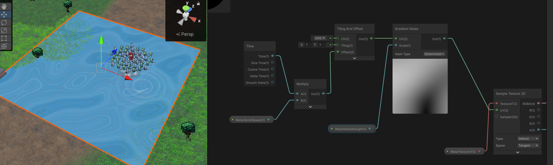
im not understanding why my water ripples are stretching with distortion like that. Only seems to occur when it's near the edges of the viewport, but if I'm right on top of it it's fine.
not really doing anything special with the UVs besides some gradient noise
When sampling outside the 0-1 ranges of the texture it'll use the same colour as the edge of the texture (assuming Clamp wrap mode)
Correct. Geometry-1 meant that it was rendering before everything in Geometry.
It can't possibly get blocked by anything later in the queue
You could also just use Geometry, although that could cause some anomalies with overlapping renderers
Even if another object winds up covering its pixels up, the stencil buffer has already been changed
It's a lot like how transparent rendering causes weird sorting issues
Yeah when I tried just geometry, it flickered wildly between in front and behind
in the same way transparent renderers can fail to sort right
I didnt see any obvious wrong layering when setting to geo+1 though
https://i.imgur.com/05vGw1V.png
https://i.imgur.com/Jj3aGoC.jpeg
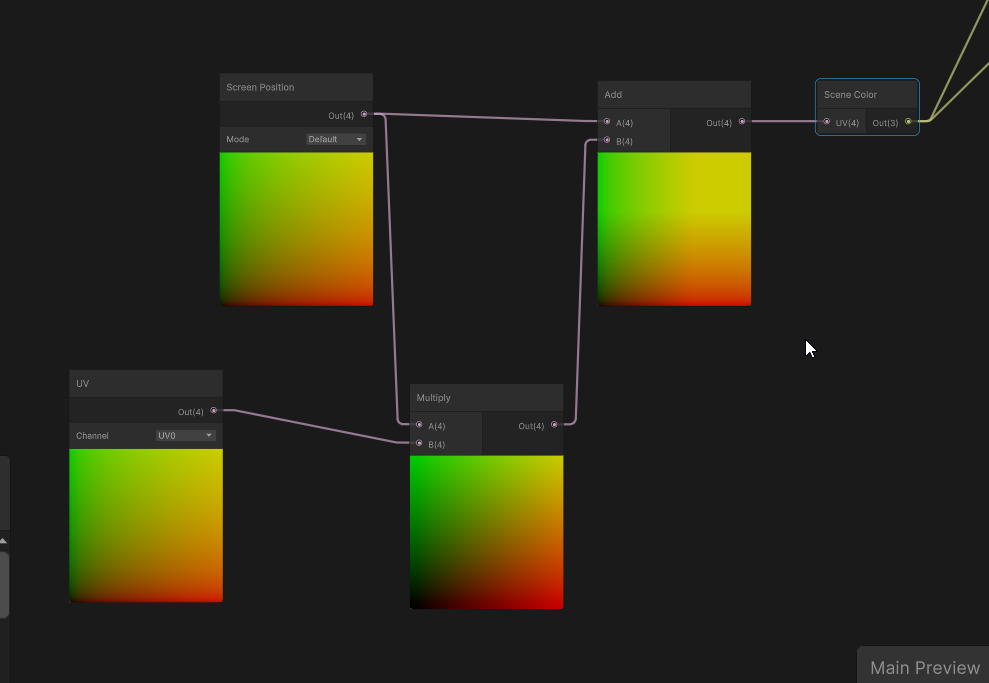
I'm just using screen position/color here like unity's example. Maybe this is expected behaviour, so maybe I'm looking for ideas to keep the sampling range of the scene color to a minimum maybe?
Maybe unity's plane is just terrible
inverse fresnel kinda fixes the issue by just not distorting on the edges I guess
Question: I'm trying to port a Kuwahara filter to a shadergraph Fullscreen render pass.
The original shader wants inputs of Texture2D and SamplerState, but what I have is the blit source.
Is this port not possible because I haven't got the blit as a texture2D? Or can it be converted to pass in the blit as a float4?

Part of me thinks this port is impossible because the shader is running per fragment and it doesn't have the kuwahara pixel quadrants to work from?

or am I wrong and the blit contains the full pass?
source shaders I am trying to port from:
https://github.com/GarrettGunnell/Post-Processing/tree/main/Assets/Kuwahara Filter
https://github.com/daniel-ilett/smo-shaders/blob/master/Assets/Shaders/Complete/Painting.shader
daniel's or acerola's adaptations, or these shadertoys
https://www.shadertoy.com/view/mlffWf
https://www.shadertoy.com/view/MsXSz4
Kuawahara needs to be able to sample neighbours so how do these other implementations work if the shadercode is only running on a single fragment, where do they get their neighbours from and how can I reproduce that in a custom code node for a fullscreen render pass?
https://www.danlivings.co.uk/blog/oil-painting-effect-shader-unity/
this person does have a functional implementation of kuawahara as a URP render feature, but the reason I am not using it and am trying to port those other versions is because this verson doesnt use the stencil buffer and I need to stencil out some things from the effect to not be filtered
and I dont know how to edit their code to add that, I am too inexperienced with writing actual code shaders vs. building them in shadergraph
this is what I am trying to do because I dont know any other way to get both a full screen pass of kuawahara and stencil buffer out part of it

The BlitSource is a texture (with reference _BlitTexture iirc). It's just that the URP Sample Buffer node already does the sampling for you.
IDK much about the Kuwahara filter in particular but I imagine it requires multiple samples. Which might be easier in a custom function node since you can use loops there.
Yeah thats exactly what I was trying to do
but the problem was all the implementations want to compare pixel regions, but I dont have pixel regions to pass into the custom node, all I have is the float4 from the BlitSource
im not aware of any way to sample the Texture2D directly in shadergraph
this is where/how im getting the blit source

If you right-click the URP Sample Buffer node you should be able to look at the generated code it uses and copy that
Oh I didnt know about that, let me look now
Something like = SAMPLE_TEXTURE2D(_BlitTexture, sampler_PointClamp, uv) maybe
note that you can't do anything with stencils in the Shader Graph, AFAIK

Fullscreen graph does have stencils now yeah
full screen pass using stencils to not write to some of them
But not other types 🙃
Ah, okay
Hey guys! Sorry to interrupt. I am wondering if anyone can help me here with something that should be simple? I want to do a swaying effect on the masked area of my model (the black and white image) but it doesn't seem to work. I'd really appreciate any help

you're dividing by zero all over the place
I found the code but how do I access this myself? Like if I want to write my own custom node that just 'gets' the unsampled Texture2D

Did you mean to multiply?
😳
Please continue
I assume this wont work for me to call for _MainTex as an input in order to get ahold of it

if the mask is meant to control the strength of the movement, you should multiply by the mask
maybe I CAN just get ahold of it?
Nope that didnt work

If you're only going to be sampling in the custom function you don't even need to define it in the blackboard. I would just define it in the hlsl file used by the custom function.
TEXTURE2D_X(_BlitTexture) & sample with the LOAD_TEXTURE_X_LOD like it does
Still not working with a multiply node

The problem I am facing is I don't know how to access it, I only comprehend inputs and outputs here, how do I make the HLSL file summon it from the same place this exposed code is using?

SO, its for a swaying effect on a specific area of a character model. Instead of applying this sway effect to the specific area of the model, it is applying it to the whole model
If I just write this in my HLSL custom node file:
"TEXTURE2D_X(_BlitTexture);"
somewhere, will it 'just work' to get that file from the inputs?
not sure why its an _X either
It doesn't need to be in inputs. Like the function defined here it's not a parameter. The texture is defined before so it's acessible from any code after it.

I assume I cannot just write it and have it just work, but I am not versed in written shader code specifics enough.
I can change stuff from vectors to floats and change returns to Outs but my ability to port is not much beyond that 🤔
Right but that's the URP sample buffer code

Does the material on the character have the mask texture assigned?
Or are you saying I should copy paste the sample buffer code, and edit it, instead of trying to write a custom node?
I am not experienced enough to know what parts to remove or not when trying to slim down the huge generated code file for the URP Sampler Buffer
or like, where to inject my new code
I know I don't know enough, but the only way to do is by trying
Yes, the model has the material assigned with the shader that uses that mask

I'm pretty sure that texture is only being used when previewing the shader in the shader graph
look at the actual material
I'm saying write a custom node using that snippet I copied from your screenshot. It shows how to define and sample the blit source texture
Right but how do I pass it in?
I think the problem is im not understanding where its coming from or how its getting it
Ill just do what you say and copy paste it completely directly
The custom function code gets compiled along with all of the other ~stuff~ in the shader
Okay so in the materials tab I see the 3 materials my character is comprised of - Are you saying there should be a 4th material for this specific area?

copying the whole thing didnt work which I assumed it wouldnt

You can declare all kinds of stuff in there, like compute buffers
TEXTURE2D_X is a macro that expands into either TEXTURE2D (in non-VR contexts) or TEXTURE2D_ARRAY (in VR contexts).

and then TEXTURE2D expands into a variable declaration
You'll definitely need to include something here
I actually don't know what, though! I've mostly done handwritten BiRP shaders
the bits of custom functions I've done in the HDRP haven't touched textures yet
It says undeclared identifier _blit texture, which I assumed since you cannot just make it summoned by writing that one line alone
The issue is that it doesn't understand the macro
Ill look in the decompile code?

generated code rather*
No.
Look at each material. Do they have a mask texture assigned?
Cyan probably knows more about that .
Assign a mask texture.
You get a white texture if nothing is assigned (by default, at least)
Here is the code from the node
Is that an error in the IDE? If so then yeah, it probably just doesn't understand the macro. I'd focus more on errors the graph spits out
Its from the node

I am not understanding how the custom node is 'getting' the blit texture2D, like nothing in the code is giving it, it cant come from nowhere
which is why I am so stuck on the idea of 'where is it passed in from'?
Where do I do this?
Because to my knowledge, it has to come from somewhere and be defined somehow to recieve
Here is the original node's generated code. I am looking over it now trying to see where the blit Texture2D 'comes from'
select one of the materials and screenshot the entire thing
All of the declarations in all of your custom functions get compiled together
I presume an include is needed.
I'm not sure how much is available to the custom function code as-is
OMAGAD I DID IT
Thanks
Appreciate the help
The TEXTURE2D_X(_BlitTexture) is what is meant to be defining the texture so I'm confused why it would say it's undefined
trying to include all the same includes didnt work, though this DOES change the error

Tbh not sure why this works?
To my understanding I cannot just write 'TEXTURE2D_X(_BlitTexture)' and have it self populate, like thats not how shader code works
but I also dont know what Im doing really
So I shouldnt run my mouth about how things do or dont work to people who DO know how they work much better than I do

the error changed after I added then removed the includes
mildly interesting that you didn't get that one the first time
TEXTURE2D_X is from Core.hlsl
hm Core.hlsl wasnt included in the original file
Probably need to surround some stuff in #ifndef SHADERGRAPH_PREVIEW. Bit annoying
why would you need to exclude that?
good to know about that, though, since I was having issues with things that use structured buffers
the preview doesn't bind the buffers (duh) and thus it broke


You would do this
#ifndef SHADERGRAPH_PREVIEW
...
#endif
The SHADERGRAPH_PREVIEW constant is defined if the shader is being compiled for display in the shadergraph preview window
oooh
#ifndef will exclude everything until the next #endif if that constant is defined
That actually worked, now the error is my method

Well, now your method doesn't exist at all when previewing the shader graph
I would put the ifndef around the TEXTURE2D_X(_BlitTexture)
Then again in the function body, but have texture = 0 at the beginning just so it's always set to something

are you sure we aren't just missing an include here...?

hmm no matching 2 parameter function it says now 🤔
the names are right
maybe I shouldnt use the name 'texture'
changed it to ouytput
That changed the error
so naming it texture was definitely a problem
I'm not sure where TEXTURE2D_X is defined but includes usually cause conflicts because SG previews have their own separate shader library so they work in all pipelines. It's a bit of a mess

Yep, that's why you'd put another #ifndef around the function call


yeah, so this will, in the shader graph preview, just set the output to zero
and then outside, it'll do everything normally
well that's a pain in the ass
okay now I DO have the Texture2D and I can pass in the sampler state
I shooould in theory be able to now continue trying to implement the kuawahara
Thanks for all the help, I wouldnt have figured that out on my own
anyone know why a shader might look different in the scene and game view?

this was just a bug but it was a pretty cool effect, i want to try recreating it in the game view
Likely a negative alpha value (based on the red colour and cyan background)
Game view target probably has some clamping. Maybe because it's not a HDR target or affected by post processing
oh right, i think i might know what caused it in that case. lemme try something real quick
tried clamping the value on the middle circle. that fixed it in the scene view. not sure how to un-fix it in the game view though.
tried enabling HDR in the player settings. i've never used it before though so im not sure if im doing something wrong
https://discussions.unity.com/t/distortion-shader-bug/869092
Guess I never cared about this issue before but yeah I guess the problem here is that your viewport is technically clamped so you run into these stretched fragments near the edges at different perspectives
The scene view renders "differently" in ways I don't fully understand
notably, the skybox is drawn...differently
i don't know how!
if you don't write to depth but still render something, that pixel does not get overwritten by the skybox in the scene view
but it does in the game view
(this is for the BiRP in particular)
im using URP, seems like most of the same stuff still happens though
https://i.imgur.com/u2iabGh.png
What's the idea around getting that lava lamp effect with textures? Currently throwing noise on it does create the shape, but throwing time on the strength doesnt give it that animated effect of a laval lamp.
Ah, maybe it's voronoi I need to stick in somewhere
https://i.imgur.com/88lsQRu.jpeg
Found some neat idea using pure noise, but this tutorial leaves off with the mask (voronoi) being part of the color map, creating these areas of darkness/transparency that I'd like to fill in with another layer of color. I assume I'd want to try to inverse the mask at some point, but I'm not sure of the tools I should be using for that.
https://i.imgur.com/I0N1tQG.png
It's a mix of noise, then throwing it inside step nodes to create these outlines and that lava lamp look
https://cdn.discordapp.com/attachments/1335395019372101632/1340197470902292550/Unity_zu6KtzypNP.mp4
Getting there once I can figure out the coloring lol Got it, just need a one-minus in the mix
but otherwise managed to do this all in the shader using render textures which is pretty cool
have to use particle systems to kinda give it information though cause I can't use compute shader with webgl
figured it out in the end. just has to switch this from 32 bits to 64 bits

I've been using a texture which is supposed to work the same across all the pipelines, and it's documentation says nothing about this, but when I switched over to URP shadows just stopped working with point lights. They still work with directional lights. Previously I was using it for every texture in the game so it's the shader for every texture in the first 2 screenshots.
1st picture is built in render pipeline which is what I've been using where the shadows work with point lights. 2nd picture is the same for everything but in URP. 3rd image is URP after I changed the floor texture to a standard URP one. Does anyone have any idea what could have gone wrong or how to fix it?


And just to prove its not dark lighting, the red floor here is URP simple lit and the yellow is toon shader

So I just finished setting up my very first ever shadergraph, and I was wondering if there is a way to make this screen a bit more compact by shrinking the preview shown of the textures to a much smaller size, similar to how unity's standard shader looks

Why yes, they seem to have added groups inside of the shader graph properties as of recent

Inside of the properties there's a 'group' you can select
assuming you've one of the latest versions
I apologize profusely because I am quite stupid, im currently running on unity 2022 for VRchat world creation, is that option available in that version of unity? this is how my setup looks currently, this is my first time using shadergraph so im still not fully familiar with all of the settings


unless shader graph isn't editor specific i'm not sure
apparently typing "hrmmm" is against the rules... so ill use an emoji instead

ah wait
im dumb
i found it
I thought that "category" was like.. the category of options i was in and not clickable

Like I said, I am quite stupid
thank you
oh noice
actually they been in for quite a while, I've always just used older versions I guess haha
one weird thing though.. it doesnt seem that I can adjust the position of my category 
its just stuck at the very bottom
I can move different categories between one another though
intteresting
well its not quite perfect but this definitely did help me make my shader look a fair bit cleaner so thank you

I have a general workflow question - I'm an experienced C# programmer. I started learning shaders by using ShaderGraph but I found the visual-scripting workflow of shadergraph very annoying (the fact that Add node can add only two numbers but not three broke me as a person). Now I want to switch to just writing shaders by hand which is much simpler and intuitive for me. We're using URP and I've heard that Unity recommends using ShaderGraph instead of custom shaders for full compatibiltiy and best performance (is that true?).
I'm wondering what would the optimal workflow be - use ShaderGraph as a shell for custom shaders (custom nodes) to avoid visual scripting workflow, or ditch ShaderGraph entirely and use only custom shaders? Is it a viable approach to never touch ShaderGraph? What would I lose by that approach?
You could create custom function nodes in the shader graph.
The main issue with urp and hdrp shaders is that the unity side API is not very well documented, so you'll need to do a lot of "reverse engineering"(or rather just reading the standard shaders and their includes).
Also, there's basically no idea support for unity includes.
Honestly, I'd just recommend to overcome yourself and use shader graph, unless it's something that is not implementable in shader graph.
OK so completely disregarding ShaderGraph is not advisable?
I think I'm fine with a mixed workflow then - use the input/output shell of ShaderGraph and add custom function nodes written in HLSL.
At least, I wouldn't advice disregarding it. It abstracts away all the implementation details of the unity graphics/shader infrastructure. Without this abstraction, you'll need to understand it as much as the engine developers do. In ideal scenario.
I'm learning shaders and transparency, and I'm kind of curious what's going on in this example - the 10 (in the very back) is being cut out by the "3". I think this has to do with the order entities are being drawn in, but I don't know much about this (or whether there is a reasonable solution).
I have some theories on what I could try, but I figured I should ask first. What's the name/cause of that clipping effect from transparencies? is there anything anyone recommends for that?

honestly the harder part is that I kind of want to ZTest the translucent pixels... but only against the solid pixels
How are your materials configured?
Trying to implement grass painting for my custom terrain system and I'm having trouble with making a 3D billboard shader in URP. I cannot use shader graph due to the fact that it doesn't properly support instancing (https://discussions.unity.com/t/urp-shader-graphs-with-instanced-indirect-instanceid-node-seems-to-give-0/249813) with the only fix to write shader via code or use custom functions that break compatibility with basically all graphics APIs apart from DX11.
My billboard code currently is extremely simple:
Varyings vert (Attributes IN, uint instanceID : SV_InstanceID)
{
    Varyings OUT;

    float3 grassWS = _TerrainDetail[instanceID].TRS._m03_m13_m23;
    OUT.positionHCS = mul(UNITY_MATRIX_P, mul(UNITY_MATRIX_MV, float4(grassWS, 1.0)) + float4(IN.positionOS.x, IN.positionOS.y, 0.0, 0.0));
    OUT.uv_MainTex = IN.uv_MainTex;

    return OUT;
}
However, it doesn't support scale. I have a TRS matrix which has the scale information but I have no real idea how to apply it.
I could see that happening if the material on the "10" is set to render later than everything else, and if the other materials are writing to the depth buffer
Multiply the terrain detail matrix with float4(0, 0, 0, 1) to get a world-space position
The problem I'm having isn't with position though
you're then multiplying that "world space position" with UNITY_MATRIX_MV, which is model * view, so that's a bit odd
the model matrix takes you from object space to world space
float3 grassWS = _TerrainDetail[instanceID].TRS._m03_m13_m23;
This is ignoring the rotation and scale described by the matrix. You're just extracting the translation from it
although, I suppose that transforming [0,0,0] would just give you the translation anyway
What does that matrix represent, exactly?
it's a TRS matrix
right, but what coordinate space is it supposed to take you from (and to?)
it's in world space
you're treating grassWS as an object-space position here, given how you're multiplying it with UNITY_MATRIX_MV
which could be reasonable: each terrain detail could have a matrix that tells you how to go from the detail's object space to the entire terrain's object space
that's what I'm thinking is happening. I'm going to try to set the transparent layer to ZTest but not ZWrite. I'll give a shot at setting the Render Queue for the transparent layer to render -after- solid queue
Transparent is 3000 and Geometry is 2000 for a reason!
If a transparent material has ZWrite turned on, then anything behind it that renders later will get incorrectly blocked
Transparent rendering kind of sucks
I've fought with this a lot when making VRChat avatars with really complicated gimmicks
in my latest project, I decided I'm just not doing any transparent rendering
problem solved ✨
Ah, I think I see the issue.
OUT.positionHCS = mul(UNITY_MATRIX_P, mul(UNITY_MATRIX_MV, float4(grassWS, 1.0)) + float4(IN.positionOS.x, IN.positionOS.y, 0.0, 0.0));
I presume IN.positionOS is the object-space position of the billboard's vertex
So you're performing the following sequence of operations:
- Get the world-space position of the terrain detail
- Multiply that with UNITY_MATRIX_MVP (in two steps, I guess?), which would go from object-space to world-space to view-space to clip-space
- Add the object-space position of the billboard vertex
since I'm working with sprites, I need transparent pixels. but I can put the solid sprites as transparent 3000 and the translucent ones at 3001
you have your coordinate spaces jumbled up
You should be doing something like this:
float4x4 detailToWorld = _TerrainDetail[instanceID].TRS;
float4 worldPos = mul(detailToWorld, IN.positionOS);
float4 clipPos = mul(UNITY_MATRIX_VP, worldPos);

OUT.positionHCS = clipPos;
Typically, alpha-clipped shaders go at 2450. I presume you're doing that.
since sprite meshes usually have some extra bits that aren't rendered
(but transparent rendering with ZWrite on would be roughly equivalent to that)
ah, I didn't know
This will correctly scale and rotate the billboards
nominally, they could get mixed in with everything else in the Geometry queue, but discarding pixels (which is how you do alpha-clipping) prevents the GPU from taking some shortcuts
it can no longer assume that every pixel under a triangle gets drawn to, basically
so they live at 2450
I should clarify that "TRS" just means "translation, rotation, scale" -- a matrix constructed out of those three things
That doesn't tell you anything about the meaning of the matrix
i.e. what coordinate spaces it moves you between
This doesn't seem to work. Objects with the material no longer appear
How did you construct that matrix?
Matrix4x4 trs = Matrix4x4.TRS(detailPos, Quaternion.identity, Vector3.one * size);
DetailObject detailObject = new DetailObject()
{
    trs = trs,
    normalOffset = normalOffset//Unused in shader
};
detailPos is the world position (obtained from a raycast from mouse to world)
okay, that seems reasonable
What is the type of IN.positionOS?
If it's float3, you'll need to construct float4(IN.positionOS, 1)
lol well my idea definitely did not work as intended
in very loose terms: float4 is used for homogeneous coordinates. If the W component is 0, it represents a vector. If the W component is 1, it respresents a position
Translating a vector doesn't do anything
note how the translation in a transform matrix is expressed entirely in the last column
and those values get multiplied by the W component of the coordinate!
so I'm drawing the transparencies later, but they aren't being 'covered' by solids

The solid objects must have ZWrite On
that fails the depth test if they're deeper than the value in the depth buffer
understood
I'm glad that this is much more doable than... sorting my sprites
that was it!
it ain't pretty but I can work on it.
last issue is just the flickering when the position moves. basically overlapping solids are fighting to be in 'front'

yep, that's Z-fighting
I'm not sure what Unity normally does about that with sprite renderers. It can decide which one wins based on the sorting order.
I guess that sprites that face towards an orthographic camera don't really have problems with z-fighting, since the entire sprite is at one exact depth
(maybe, not sure..)
it's float4
struct Attributes
{
    float4 positionOS   : POSITION;
    float2 uv_MainTex   : TEXCOORD0;
};

struct Varyings
{
    float4 positionHCS  : SV_POSITION;
    float2 uv_MainTex   : TEXCOORD0;
};
hm, that should be a valid position, then
I'll do some experimenting to find out. one of the things I made sure to include in my rendering was room for 'offset' on everything, even z
can you show me the current shader?
so I may go as far as to inject a tiny offset based on the entity id
thanks for your help!
Hm does anyone have a repo of the 'language' that shadergraph's custom nodes expect?
For example my specific issue right now is I am trying to port a shader to custom nodes.
The shader uses 'tex2D' and I know I have to change that to something equivalent
I am more interested in learning how to find this answer myself not be hand fed each specific instance of 'change this to that'
That's a question I'm figuring out myself, haha
Im pretty sure tex2D needs to become something like 'SampleTexture2D'
I think I used to know or had a resource that had equivalences written in it
maybe something cyan wrote one time
it was like a 2 column table of shader methods and their shadergraph custom equivalents
When you use tex2D, you're using one very specific way to sample a texture
it's an HLSL function
SAMPLE_TEXTURE2D can expand into the appropriate function for your target platform
I've used the various methods somewhat randomly while working on VRChat avatars
So, if you're writing a custom function node for a scriptable render pipeline shader, you should try to use the core RP macros
"when in Rome..."
yeah I want to be using the correct macros
I am still unclear on how you're supposed to figure this out from the documentation alone, though
you'll often see an entire chain of macros
TEXTURE2D_X(foo) -> TEXTURE2D(foo) -> sampler2D foo
The first step is in the Core.hlsl include
The second step is in platform-specific includes
Looking in core now sometimes I am uncertain what something is asking for, like SAMPLE_TEXTURE2D wants 'textureName, samplerName, coord2'
I am guessing those are a Texture2D, SamplerState, and a float2 for uv?
Whwere would I learn that info however, since it isnt written to say 'samplerstate'
SAMPLE_TEXTURE2D_X(textureName, samplerName, coord2)
Core.hlsl turns this into
SAMPLE_TEXTURE2D(textureName, samplerName, coord2)
D3D11.hlsl turns this into
PLATFORM_SAMPLE_TEXTURE2D(textureName, samplerName, coord2)
and then into
textureName.Sample(samplerName, coord2)
You can also just write the last bit directly, but that means your code only works on DX11
Shader "Instanced/Grass" {
    Properties {
        _MainTex ("Albedo (RGB)", 2D) = "white" {}
        _Diffuse ("Diffuse", Color) = (1,1,1,1)
    }
    SubShader {
        Tags { "RenderType" = "Opaque" "RenderPipeline" = "UniversalRenderPipeline" }
        Pass {
            HLSLPROGRAM

            #pragma vertex vert
            #pragma fragment frag
            #pragma multi_compile_fwdbase nolightmap nodirlightmap nodynlightmap novertexlight
            #pragma multi_compile _ _MAIN_LIGHT_SHADOWS
            #pragma multi_compile _ _MAIN_LIGHT_SHADOWS_CASCADE
            #pragma multi_compile _ _ADDITIONAL_LIGHTS_VERTEX _ADDITIONAL_LIGHTS
            #pragma multi_compile _ _ADDITIONAL_LIGHT_SHADOWS
            #pragma multi_compile _ _SHADOWS_SOFT
            #pragma target 4.5


            #include "Packages/com.unity.render-pipelines.universal/ShaderLibrary/Core.hlsl"


            struct DetailBuffer {
                float4x4 TRS;
                float normalOffset; //Unused
            };

            CBUFFER_START(UnityPerMaterial)
                StructuredBuffer<DetailBuffer> _TerrainDetail;

                sampler2D _MainTex;

                float4 _MainTex_ST;
                float4 _MainTex_TexelSize;

                float4 _Diffuse;
            CBUFFER_END

            struct Attributes
            {
                float4 positionOS   : POSITION;
                float2 uv_MainTex   : TEXCOORD0;
            };

            struct Varyings
            {
                float4 positionHCS  : SV_POSITION;
                float2 uv_MainTex   : TEXCOORD0;
            };

            Varyings vert (Attributes IN, uint instanceID : SV_InstanceID)
            {
                Varyings OUT;

                float3 grassWS = _TerrainDetail[instanceID].TRS._m03_m13_m23;
                OUT.positionHCS = mul(UNITY_MATRIX_P, mul(UNITY_MATRIX_MV, float4(grassWS, 1.0)) + float4(IN.positionOS.x, IN.positionOS.y, 0.0, 0.0));
                OUT.uv_MainTex = IN.uv_MainTex;
                return OUT;
            }

            float4 frag(Varyings IN) : SV_Target
            {
                return tex2D(_MainTex, IN.uv_MainTex) * _Diffuse;
            }

            ENDHLSL
        }
    }
}
Yeah dont want to hem myself into one specific thing 🤔
i want to see what you implemented based on what I suggested
I'm kind of surprised this worked at all, because you're adding the object-space vertex position to the clip-space position. Those coordinate spaces have nothing to do with each other
just replace the code between Varyings OUT; and return OUT; with the code you posted here
you'd also need to set the uv coordinates
doesn't change anything
that could cause the shader to not compile (i'm not sure why it only sometimes does that when you don't completely initialize the output struct)
show me the resulting vertex stage
Varyings vert (Attributes IN, uint instanceID : SV_InstanceID)
{
    Varyings OUT;

    float4x4 detailToWorld = _TerrainDetail[instanceID].TRS;
    float4 worldPos = mul(detailToWorld, IN.positionOS);
    float4 clipPos = mul(UNITY_MATRIX_VP, worldPos);

    OUT.positionHCS = clipPos;
    OUT.uv_MainTex = IN.uv_MainTex;
    return OUT;
}
If you replace detailToWorld with unity_ObjectToWorld, do you wind up seeing all of the billboards overlapping at the origin of the terrain renderer?
bit of a sanity check
Cannot Convert from Const Struct UnitySamplerState to SamplerState

I'm guessing I should use UnitySamplerState instead
or maybe not

ill try it anyways since VS code doesnt always know

no errors in shadergraph but errors in the console
Not sure what it means by SampleBias, something to do with samplers?

this is the line it seems unhappy with
ill look for other methods than SAMPLE_TEXTURE_2D
i haven't had to sample textures yet from a custom function, so i've never really dug into this

check it out 👀 screen-space Kuwahara through shadergraph and a fullscreen renderer feature pass, filtered to only specific things via stencil buffer
https://paste.ofcode.org/yhiVPVdrTu3YmuaYpeCvNw here is my code block I run in a custom node.
The code itself is a port of https://github.com/daniel-ilett/smo-shaders/blob/master/Assets/Shaders/Complete/Painting.shader
That's the standard regular Kuwahara, now that I have it working Ill take a look at the generalized and Anisotropic versions
nope
the graph being just 'pass in the stuff and return result'

but you did see billboards appearing at the correct positions (just without the scale) with your original code?


D'oh. Your code makes a lot more sense now: you're billboarding, so you just use the vertex positions to offset the view-space position
Now I see why you're doing that.
It's a bit weird because your TRS matrix needs to be used for two different things:
- the position of the billboard (in the world)
- the size of the billboard (in view-space)
You can extract a scale from a transform matrix
It might make more sense to just pass in a float3 for the position and a float for the scale
I am surprised my code didn't draw anything, though. I wonder if they're just facing away from the camera here
But it's definitely not right -- mine would be appropriate if you wanted to draw a non-billboarded mesh
hrm. so in this sample shader, rotated objects scale after they are rotated, not before: https://coffeebraingames.wordpress.com/2022/10/04/sorting-a-million-sprites/
I don't suppose there's a way around that...

When I wrote this article in 2020 about rendering a million sprites, I was also writing a 2D rendering framework using this technique combined with DOTS. I was planning to use this framework for Ac…
they are flat-scaling (a float), wheras I've been changing it to float2
I could attempt to calculate new scale based on sin and cos but I wasn't sure that was needed?
Do i need a shader to make it seamless? These are mesh gameobjects, not terrain
You probably just need to UV unwrap the mesh better so the seams of the texture connect properly (assuming the texture itself is seamless)
The meshes are multidirectional. Even if the floor UVs merge with some walls they will not merge with others (seamlessly)
I think
IDK what "multidirectional meshes" are but if you are using box-projection or some other type of automatic UV projection for the textures, you'll likely need to enable smooth shading for all vertices/edges.
I just mean if you use a texture with some uvs on the ground tile, and then place walls around it, only some walls will be joining the ground seamlessly
https://i.imgur.com/bpGemVB.jpeg
https://i.imgur.com/LSMoslf.png
Trying to make an intersection shader to create soft edges, but I'm having trouble figuring out what needs to be changed here to work with orthographic projection. It currently works just fine with perspective and from what I've read this should also work fine for ortho or maybe I'm missing something.
Edit: Think I fixed but no idea why :D
It actually kinda works above the character, but below them does the depth not seem to be calculated correctly.
Have you tried just playing around with the scene lighting environmental settings?
Does unlit not allow shadows? That's actually odd, but I would expect you can add them in with your own custom unlit shader.
it doesnt, at least in my case
Not sure, gonna fiddle around more i guess
yeah that was the problem.
BIllboarding doesn't really work anymore now.
Updated code:
struct Attributes
{
    // The positionOS variable contains the vertex positions in object
    // space.
    float4 positionOS   : POSITION;
    float2 uv_MainTex   : TEXCOORD0;
};

struct Varyings
{
    // The positions in this struct must have the SV_POSITION semantic.
    float4 positionHCS  : SV_POSITION;
    float2 uv_MainTex   : TEXCOORD0;
};

Varyings vert (Attributes IN, uint instanceID : SV_InstanceID)
{
    Varyings OUT;


    float4x4 detailToWorld = _TerrainDetail[instanceID].TRS;
    float3 worldPos = mul(detailToWorld, IN.positionOS);
    float3 viewPos = TransformWorldToView(worldPos) + IN.positionOS;
    float4 clipPos = TransformWViewToHClip(viewPos);


    OUT.positionHCS = clipPos;
    OUT.uv_MainTex = IN.uv_MainTex;

    return OUT;
}

Oh hey I think I've taken that code from that repo before
I was actually looking into a similar idea, but I just went ahead and used Unity's terrain and detailed meshes
Also, do note that if you use spriterender that billboarding like this won't work unless you remove dynamic batching, even if it's instanced I noticed it was creating problems.
How do you go about populating the terrain with the objects? Do you still use gameobjects or is this some sort of splatmap of values you're reading from?
it is instanced geometry
right, but this is done by values, you still need to represent that on the editor somehow
so is this like an array you feed these positions into?
I was thinking like making a custom brush that populated gameobjects, and then feed those transform values into shader. After, strip those gameobjects at runtime.
Either that or splatmapping randgen

keep in mind the only issue here is the vertex shader not working correctly.
nothing else is relevant
oh yeah that looks pretty good
float BillboardVerticalZDepthVert(Attributes IN, inout Varyings OUT)
{
    // billboard mesh towards camera
    float3 vpos = mul((float3x3)unity_ObjectToWorld, IN.positionOS.xyz);
    float4 worldCoord = float4(unity_ObjectToWorld._m03, unity_ObjectToWorld._m13, unity_ObjectToWorld._m23, 1);
    float4 viewPos = mul(UNITY_MATRIX_V, worldCoord) + float4(vpos, 0);

    // view to clip space
    OUT.positionCS = mul(UNITY_MATRIX_P, viewPos);

    // calculate distance to vertical billboard plane seen at this vertex's screen position
    float3 planeNormal = normalize(float3(UNITY_MATRIX_V._m20, 0.0, UNITY_MATRIX_V._m22));
    float3 planePoint = unity_ObjectToWorld._m03_m13_m23;
    float3 rayStart = _WorldSpaceCameraPos.xyz;
    float3 rayDir = -normalize(mul(UNITY_MATRIX_I_V, float4(viewPos.xyz, 1.0)).xyz - rayStart); // convert view to world, minus camera pos
    float dist = rayPlaneIntersection(rayDir, rayStart, planeNormal, planePoint);

    // calculate the clip space z for vertical plane
    float4 planeOutPos = mul(UNITY_MATRIX_VP, float4(rayStart + rayDir * dist, 1.0));
    float newPosZ = planeOutPos.z / planeOutPos.w * OUT.positionCS.w;

    // use the closest clip space z
    #if defined(UNITY_REVERSED_Z)
    newPosZ = max(OUT.positionCS.z, newPosZ);
    #else
    newPosZ = min(OUT.positionCS.z, newPosZ);
    #endif

    return newPosZ;
}```
This is what I use for my grass/foliage and it's based off of one of bgolus' shaders. It prevents the billboards from clipping into 3D geometry behind them at larger angles with a perspective projection.It's also based on that repo code but changed somewhat.
I think Unity's grass shader has some similar behaviour, but I do notice that it does clip at very large angles Actually, I'm thinking of another shader that Unity provides
Ah, actually the repo code there billboards around the y, so yeah there's somewhat of a difference in behaviour
rather, it does not preserve the y rotation
do you guys know if theres a way to write directly to the final fragment color in a lit shader graph
Not really possible. But outputting to emission should have a similar effect.
unfortunately when I try that, evne with base color at black and everything else at 0, i still get this weird effect, idk if its from AO or what
What effect?
emission would only work if the color you output into it is brighter than the lit color that unity calculates
unlit (left) lit (right)


What is the problem though?
look at the shaded section on the left of the face, I dont like how the lit shader auto adds that lighting
perhaps there is a way to make the default color negative then? Didn't know thats how it worked
Maybe it's due to the specular component of the lighting? Did you try setting specular/metallic to 0 and unchecking specular reflections in the material?
I don't think that's possible
Why not use an unlit shader though, if it produces an image that you expect?
looking into this rn, the reason I wanted to use the lit shader is because it has shadow functionality and pretty much all URP features built into it so that I can easily access their values and modify them
But it looks like you have some shadows in the unlit shader as well? Some kind of cell shading
btw you fixed it, I changed from metallic to specular and set specular to 0 and its good now, so thanks!
no shadows rn, just dot product shading (and a little extra stuff 😉 )
and textures
I am attempting to use shadergraph to make it possible to rotate a texture on an object by a specified amount, not to have it fully animated allthe time and i thought i set it up right, but whever i rotate the texture just gets very deformed
this is my setup currently

however when i adjust the rotation it rotates... but also zooms in a ton, i can sort of fix it by reducing the tiling but id like to avoid that

am i just using the wrong math node to combine these?
wheb you say rotate the texture do you mean just rotating the 2d texture in the uv map either clockwise or counter clockwise?
yes
so like say i havea countertop
and i want the wood planks to go a certain direction on it
instead of opening up the model and editing the uvs, id like to be able to just use the material to rotate it instead
ofc, let me take a look
thanks! I can show my entire shadergraph if oyu want
its likely a bit.. messy. This is my first time ever using shadergraph lmfao, but im attempting to recreate a shader that has the full functionality of the old alloy shaders since those are some of my favorite ever lol, and then adding a bit more functionality on top of it
The first issue I see is that you are using time and offset wrong
time will start at 0 and go to infinity, so you are adding too much offset and its causing this distortion
time?
oh
thats just for texture scrolling
not related to rotation and tiling and stuff
i set that up to allow me to created animated scrolling textures if i want to
that functionality works just like it does in alloy https://gyazo.com/1d982374539dfc86ad14b9f9344d597f

well ok so whenever you have multiple transformations with uvs, its usually better to chain them together using the uv inputs, you just have to be careful of the order
unless I'm misunderstanding what your using the tiling and offset node for
tiling and offset nodes are just for exactly what they sound like, being able to adjust the tiling and offset of the texture whenever i want to
the scrolling is just an optional animated version of the offset
i can set to 0 if i dont want to use
so If you just want a basic rotation texture effect, what you would do is take your sample texture 2d node, and plug the rotate uv node into the uv of the sample texture 2d node
is there a way to do that while ive already got the tiling and offset and scrolling options already plugged in there as well?
my goal is just to have all of these as optional things i can do at any time

you can plug the tiling and offset into the uv of the rotate node and that should work
okay so i have the rotate node in the wront place...
one sec
wait i thinki get it
so i dont even need a math node for this?
AHA
THANK YOU
i was overcomplicating it with the math node
the add node? No not really, but its useful to know that a lot of the uv nodes are actually just math nodes, like tiling and offset is just addition and multiplication
np
now if only i could figure out what number on the float node equates to a 90 degree angle
seems to be about 3.14
im pretty sure it uses radians, so 3.14/2 should be 90 degrees
you can use the degrees to radians math node to convert
just plug my rotation float into this?

no it should be degrees to radians
sorry for all the questions i am brand new to shader graph and dont have a clue what most nodes do yet
gotcha
so plug my rotation float node into that?
yeah that will convert your 90 degrees rotation into radian units, which is what many of the nodes use by default
np, gl
Up until now ive only worked wth unity 5.3.5 making mods for a specific game that requires that version
so i am very much enjoying this shader graph stuff
It gives me the degree of control i like over my materials that blender has while still having a quick and easy setup once your material is made like unity
Yeah shader graph is super fun, and its useful even if you know how to write shaders
my goal here is to recreate the functionality of this since its deprecated now and does not seem to work in modern unity

Add depth to your next project with Alloy Physical Shader Framework from RUST LTD.. Find this & more VFX Shaders on the Unity Asset Store.
which is a massive shame because its genuinely one of the best shader frameworks ive ever had the pleasure of using
when i try to load it into newer unity though the custom ui is completely busted and most of the functionality doesnt work right 
I wish someone would update it for newer unity, its open source, you can even get all the code on github
now if only i could find a way to make the actual ui of my shader itself more pretty to look at xD Being able to create the collapsable categories was nice but id love to be able to adjust the size of the imagte previews as well to not take up so much space

the potential for things you can do with this shader graph stuff is awesome i love it
the nodes dont feel quite as straightforward as the ones in blender, but this still feels easier for me to understand than unreal's shader graph stuff
hello, is it possible to make a cutout shader where the object is cut by objects intersecting it?
you mean like this ?
now that i think about it, im not actually sure how you'd do it 
I'm trying to create an effect where i have a hexagon split into 4 triangles that need to be colored in different colors. Very new to shaders or graphics in general. I have created the following mesh through code, and tried just coloring the vertices to the colors that i wanted but expectedly that causes a gradient or blending due to the topleft vertex being shared across all triangles.
What's the proper way of giving these individual colors, or possibly even textures. Should i just instead create 4 vertices at the topleft spot and then treat it as 4 separate meshes, or is there a smarter way

You can use 1 mesh but don't have shared vertices between the triangles
would i create unique vertices at that same topleft corner to achieve that (9 vertices instead of 6)? i still want this sort of shape in this case
You got 4 triangles so that would be 12 different vertices
oh right whoops, forgot the others are shared between two triangles too
Then you can use vertex colors without blending/gradient
and if i wanted to use different materials or textures, would i opt for submeshes instead?
Yeah, materials are per-submesh
Thank you!
Black screen on launch, Unity 6000.38 URP GPU Resident Drawer + APV enabled.

Probable link to a shader bug, linked to APVs
I am trying to make field of system like darkwood, is this possible with shaders only? my idea was to create something that just gives back saturation when something inside it. if shaders enough I would be grateful if someone gave me resources to learn from.

You need a way to give that information to the shader
wdym
you'll definitely use a shader to adjust the saturation, but it's not going to be able to figure out which areas you can and can't see by itself
if you're using the 2D URP renderer, that has a 2D light system
yes I want to use 2d light system tho
what you think I should learn to accomplish this?
https://docs.unity3d.com/Packages/com.unity.render-pipelines.universal@12.0/manual/2d-customlit.html
I remember playing around with this a while ago
You can get a texture that tells you how brightly lit an area is
Instead of multiplying that with sprite color, you'd use it to adjust the saturation
I don't remember many details, though. Been a hot minute!
well, it sounds like cheap way of making it, like I have to put material to every new sprite and get limited to single material. is it possible to write whole renderer for it?
or is it too ambitious?
afterall it sounds simple you just desature whole render and then don't desatured masked area
I feel like you should be able to do this as a post-processing effect...
alright I will check it out thx
Hey people, can someone tell me if alpha blended transparency would perform better than a simple opaque shader with clip() on mobile
I'm pretty sure I've read a bgolus post or two talking about this
https://discussions.unity.com/t/is-alpha-test-still-the-evil-for-mobile/684417/9
My own understanding is pretty weak here
I want to make fog apply less to self illuminated parts of the texture, how should I do this? (this isn't working great). I don't really understand what the density value of the fog node actually is

I think it's 0=no fog, 1=full fog. (and inbetween values depends on values in the Lighting window since it can be linear, exponential or exp squared)
Maybe try saturate(Density - illumination)
is it possible to make a light projection shader in shadergraph? I dont want to use unity lights, just want to make a textured mesh project its emissive onto any surface it intersects

you can use decals
thats in universial shader?
im trying to use the built-in VRC target
thanks this got me where I wanted 🙏
yeah you can use shadergraph to modify decal
Or you can use cookie atlast in light
cookie atlas?
Yeah you're right
light cookies in unity lights? I cant use these lights in this scenario...

then you would need to use Decals
Thanks! I tested it out myself and opaque shader with alpha clipping is way faster. Anything that can replace actual transparency is better
I tried this on a pretty old mobile phone. Redmi note 7, snapdragon 660. As per the results, dithered transparency should be more performant too. This may or may not be true for even older mobile devices
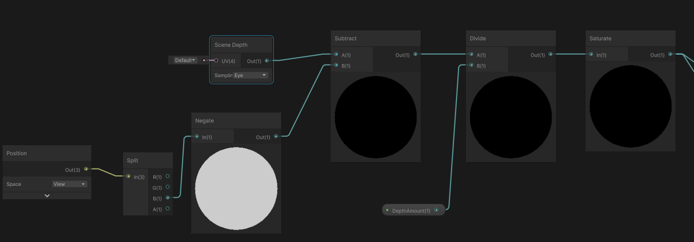
How do I get Scene Depth from within a custom function node? As in sample in the code not passed in.
For scene blit I was able to 'Show Generated Code' to see how the URP sample buffer gets the Color texture, but you can't do that on Scene Depth to see how depth is gotten in the same way

As in like, what do I put here:

This works in Shadergraph but not in the actual scene


ok, i will try that
Tho.. I did already a a couple days ago and couldnt get it to work properly.. but ill try it again
bgolus on the net says "Just use the built in Scene Depth node"
so XY problem what I am REALLY trying to do is make an outline shader that doesn't suck, roberts cross sucks, but to do more advanced ones I need to run the outline code in a Custom Function node, and to do that I need to be able to sample and offset the scene depth inside the custom function, it cannot be passed in from the Scene Depth node (as far as I know) 🤔
Should be able to use
float RawDepth = SAMPLE_TEXTURE2D_X(_CameraDepthTexture, sampler_CameraDepthTexture, UnityStereoTransformScreenSpaceTex(ScreenPosition)).r;
No need to define the texture and sampler as the Fullscreen Graph generated code does it automatically.
But like before, needs to be inside an #ifndef SHADERGRAPH_PREVIEW block.
For converting to Linear/Eye modes can use
LinearDepth = Linear01Depth(RawDepth, _ZBufferParams);
EyeDepth = LinearEyeDepth(RawDepth, _ZBufferParams);
SampleSceneDepth(uv) might also work, if inside #ifndef SHADERGRAPH_PREVIEW
(As it's a function in DeclareDepthTexture.hlsl)
I did this and it.. doesnt work? is there more to the setup?

That worked when using UV as my ScreenPosition, thanks Cyan 👍


How would I have known to call those specifically named methods? Like besides just being experienced enough to know to call them, is there a repo somewhere with this info?
Also, shown here, I fear Roberts Cross isnt my real issue, the part about it that I don't like is how the lines aren't aliased, and they cease to exist abruptly as you zoom out in weird ways 🤔
Will researching implementations like the Sobel filter fix this to not occur? Or am I barking up the wrong tree?

Mostly need to know the ShaderLibrary and check generated code. In this case, you could check the generated code for the Scene Depth node and find it uses a long macro (SHADERGRAPH_SAMPLE_SCENE_DEPTH). Searching the ShaderLibrary you can find that is defined in ShaderGraphFunctions.hlsl in each render pipeline's ShaderLibrary. In URP that uses a function from DeclareDepthTexture.hlsl
iirc the Fullscreen Graph automatically includes that, but for other graph types you'd need to include it manually (in the custom hlsl file, before function, likely inside #ifndef)
In my case I've been down that rabbit hole before when trying to use Scene Depth in the vertex shader, which requires the _LOD version of the sample. https://www.cyanilux.com/faq/#sg-scene-depth-lod
So I just used that as reference here
https://bgolus.medium.com/the-quest-for-very-wide-outlines-ba82ed442cd9
Yeah check out his blog for the jump flood alg idea?

Yeah its a good article
https://ameye.dev/notes/rendering-outlines/
Also another good resource

🖍️ Explaining multiple techniques for rendering outlines and highlights for real-time applications. This includes vertex object-space as well as screen-space methods. This can be used to render outlines in Unity or Unreal. Outlines can be used for gameplay reasons or aesthetics.
the problem is that I can't really use it in VRChat
since I can't bounce back and forth between two RTs
I can only do something truly fucking awful: repeatedly GrabPass
stencil silhouette seems to work for most of my cases. I find trying to do those toonshader outlines (rim outlining?) to be a pain in the ass
Idk about other outline techniques but if you do the blit/fullscreen pass before post processing you should be able to use SMAA to apply antialiasing. (option is on camera). Though you only get that in game view, not scene iirc.
I know sobel is more samples, so is probably more accurate than Roberts Cross
I will re-read that article but I am not looking to outline a single thing, I was looking to get edge pop out on terrain geo in like a '2D terrain has a black outline' style look


Which roberts cross does okay at the outline part, but as you zoom out it acts funny which is not ideal
Yeah, I can't seem to really get those fullscreen outline passes to work that well either
but will a different edge detection method fix this specific issue? Or is the issue related to using scene depth? 🤔

my current implementation is a 4way roberts cross, but I learned from here: https://www.reddit.com/r/Unity3D/comments/taq2ou/improving_edge_detection_in_my_game_mars_first/
to use the dot product of the world normal and view normal to eliminate overlining on steep angles


I have other effects I want to pratice so this I think its good enough for now
I would like stuff like antialiasing on the line, but doing that will require a different method than roberts cross
a real quick quesion for the shader graph, can someone tell me where to find all the properties that I can read like "_MainTex" or "_NormalMap"?
I keep finding them randomly online but I can't figure out what all of them are
idk if this is relevant but its for URP 2d sprite unlit

I see various people saying "name it _MainTex and reference it to _MainTex" and then it just magically has the main texture property. I dont really care that it works in this mysterious manner, I just really want to know where these are coming from
The SpriteRenderer component passes the sprite texture into _MainTex. And any other textures if they are set up as "secondary textures" on the sprite. https://docs.unity3d.com/6000.0/Documentation/Manual/sprite/sprite-editor/secondary-texture/add-secondary-texture.html
Those can be named anything, but _NormalMap and _MaskMap are common ones - and are used by the provided URP shaders (i.e. Sprite-Lit-Default) so using those keeps it compatible with multiple shaders
I mean where can I find all of the things like "_MainTex" or "_MaskMap"
I know there is more
is it just these?

Properties can be named anything, it depends on the shader
Other than _MainTex of course. And a few stencil ones that UI shaders expect.
well I have a different question also about shaders
so why does setting a UI element to use the Sprite-lit-default material, or any custom material, cause it to stop being maskable?
Probably because those shaders don't have the stencil properties & block, as masking relies on those
_StencilComp ("Stencil Comparison", Float) = 8
_Stencil ("Stencil ID", Float) = 0
_StencilOp ("Stencil Operation", Float) = 0
_StencilWriteMask ("Stencil Write Mask", Float) = 255
_StencilReadMask ("Stencil Read Mask", Float) = 255
and
Stencil
{
    Ref [_Stencil]
    Comp [_StencilComp]
    Pass [_StencilOp]
    ReadMask [_StencilReadMask]
    WriteMask [_StencilWriteMask]
}
they seem to be referencable properties (except the write/read mask ones)
except multiplying the alpha or setting the sprite mask with those properties doesn't seem to fix the issue
colors used to highlight issue


those properties seem to be fully 0 no matter if the UI is being masked or not
the following shows fully black no matter where the UI is

same for stencil and stencilop as well
MaskTex seems also to not do anything, although I rather suspect its a different kind of masking rather than UI masking
For graphs you're meant to use the Canvas Graph type in Unity 2023.2+
Older versions don't have proper UI support, though you can edit the generated shader code to add the stencil block in. I have info / an example here : https://www.cyanilux.com/faq/#sg-ui
yeah im in unity lts 2021
def should update it to unity 6 but crazy to know that it just isnt supported
so if I use unity 6 will they work properly?
I believe so
doesn't appear to be working
do I have to do something special with these properties or something?
I am just plugging them into the base color atm to check their values
they are just one solid color every time
If you're in Unity 6 you don't need to add the properties. But change the graph type under the graph settings to Canvas

I feel like a big dummy, but I'm trying to make a PBR Shader Graph. Do I need to enable something for that setting to come up, or was there an update I missed/
It was renamed to Lit Graph
Oh. Okay, that makes sense.
What are possible reasons why the distance from the camera to the surface causes an Edge Detection shader to say -everything- is an edge? 
The effect is also worse in Game scene than it is in Scene view

This problem occurs in both a Roberts Cross and a Sobel implementation of edge detection so I think the problem has something to do with the unity Depth buffer causing this? Rather than being from the implementation because both have the same issue

works great in scene but in game it picks up a huge angle of values hmm

possibly the reason for the problem is because im using raw depth?
googling I found this, maybe near/far clip plane differences are the issue

difference in clipping plane between scene and game does appear to be responsible 👀
For some reason shadows just don't work with this. To be honest I don't really know much about shaders.
https://scriptbin.xyz/etejizanac.m
Use Scriptbin to share your code with others quickly and easily.
Did Albedo get removed from the Lit Shader Graph or something.
Also, is Render Face: Both the same as the former Two-Sided checkbox that used to be around?
this.. isnt going well

No? Albedo is the output color - the first output channel.
Probably. You can check for sure in the docs.
Okay, so the base color, just with a different name.

I'd have a look at the console log
Yeah, the scene view can get some crazy near and far clip distances
Every power of two that separates them halves depth precision
so 1..4 is twice as inaccurate as 1..2
this means that as you start pulling the near clip in really close, you can dramatically reduce precision
0.01 vs 0.1 seems tiny, but that's just over three powers of two
theres nothing in the log
I have looked around and other peoples code just... work.. mine doesnt even have any errors in the log
Ok. Just to make sure I understand the issue correctly: it's the preview showing purple color?
the preview and the object with the shader is showing purple color
Okay. Does it happen if you disconnect all the nodes from the shader output?
It happened when I did that too
Ok, then perhaps you don't have urp installed correctly(or at all?)
Does changing the active target to something else fix it?
I have noticed how any sort of transparency or overdraw completely kills performance on mobile. Would that mean having saturation and contrast control functions within our shaders is better than using any fullscreen effect?
Just a question outta curiosity
I do have universial render pipeline installed.
Adding any other active target fixes the pink

however when its 'fixed', it just.. doesnt work, theres the texture on the ends of the cylinder, but it doesnt get projected to any of the meshes it intersects with

"Projected"? Is that a full screen shader or something?
no like.. how this other light i just spawned projects onto that surface with a shader. its a DMX light that I spawned here, and I am making my own custom DMX light, but I havent gotten the projection to work

Still having issues with my billboard shader.
struct Attributes
{
    // The positionOS variable contains the vertex positions in object
    // space.
    float4 positionOS   : POSITION;
    float2 uv_MainTex   : TEXCOORD0;
};

struct Varyings
{
    // The positions in this struct must have the SV_POSITION semantic.
    float4 positionHCS  : SV_POSITION;
    float2 uv_MainTex   : TEXCOORD0;
};

Varyings vert (Attributes IN, uint instanceID : SV_InstanceID)
{
    Varyings OUT;

    float4x4 detailToWorld = _TerrainDetail[instanceID].TRS;
    float4 worldPos = mul(detailToWorld, IN.positionOS);
    float3 viewPos = TransformWorldToView(worldPos) + IN.positionOS.xyz;
    float4 clipPos = TransformWViewToHClip(viewPos);

    OUT.positionHCS = clipPos;
    OUT.uv_MainTex = IN.uv_MainTex;

    return OUT;
}
The billboards don't correctly point to the camera. I think it has something to do with the scale part of the TRS matrix (which is in world space) since the smaller the scale, the more it points towards the camera (but somewhat stretches)

I have no idea what to do. Every example I find on billboard shaders is either for non-instanced geometry and ends up confusing me when attempting to adapt it for use with instanced geometry or it's with shader graph which I'm not using (and will not use)
hm.. could my idea be done via stencil too?
You're seeing that behavior because you're first computing a world-space position for each vertex (as if you were drawing a normal mesh) and then adding in the object-space position of the vertices on top
the first half is from my (incorrect) shader code
is stencil buffer available in shadergraph or do I need to do it in C#?
If you get rid of the + IN.positionOS.xyz; bit, you should see a bunch of normal planes sticking out of the gorund
ya
in a hand-written shader, you mean? that'd be ShaderLab (which contains HLSL)
To get the position alone, you'd transform float4(0,0,0,1) to world space
note that directly adding the object-space position to the view-space position will mean that the planes have the same on-screen size at any range
which may not be what you want
yea
High Level Shading Language?
correct
I believe you can use stencil operations in full-screen pass URP shader graphs
but you can't use it in other kinds of shader graphs
Ah that makes sense. Got it to work by doing this
float3 scale = float3(length(detailToWorld[0].xyz), length(detailToWorld[1].xyz), length(detailToWorld[2].xyz));

float4 worldPos = mul(detailToWorld, float4(0.0,0.0,0.0,1.0));
float3 viewPos = TransformWorldToView(worldPos) + IN.positionOS.xyz * float3(scale.x,scale.y,1.0);
float4 clipPos = TransformWViewToHClip(viewPos);
ah yeah, and that lets you extract a scale from a transform matrix
Is there a tool that can take an existing shader and convert it into a shadergraph shader?
dont think so. a lot of shader code cant be directly converted into shadergraph nodes, as far as i know
closest thing i can think of is chatGPT. although that has a few obvious limitations
ah I see...
hm...
Does making a shader which changes the prop texture based on location (either via noise texture or some other position based logic) have performance merit?
the idea being instead of having multiple materials for, a rock, say, you have a blend of textures and they are automatically applied based on location, all with the same shader and material?
If it is to change the texture globally on an object, it is probably better to have two materials, and let the batching system (srp batcher) group the draw calls together.
So, let's say, as an example, it would then be better to make a simple script which will randomize the objects from an array to place props around, rather than making the shader change their textures based on location?
I think so yes. You could always try both and profile to be sure.
But in theory, the 1rst option will have multiple materials using the same shader but different textures batched together.
The second, even if the texture swap is determined by the object position for example, the shader is a bit more complex. The additional randomization needs a bit more logic, even if it ends up being uniform over the whole object so only one texture is sampled.
ok thank you
I want to make lots of shaders for practice, but if it's not very useful, I will skip those particular ones
Hi again !
I've been working on an unlit shader graph to get every light source (so recreating a lit shader, kinda). It will be used later for another shader, and I needed every light node to be different (if I ever want to disable one light or smth).
Currently, I have SSAO, main light with shadows, additional lights, but I can't manage to get shadows from them.
I know that there's something named MainLightShadow for the main light shadows, but I can't find something similar for the additional lights.
How can I do ?
void AllAdditionalLights_float(float3 WorldPos, float3 WorldNormal, float4 Shadowmask,
        out float3 MixedColors)
    {

        #ifdef SHADERGRAPH_PREVIEW

            MixedColors = 1.0f;

        #else

            int lightCount = GetAdditionalLightsCount();

            for(int i = 0; i < lightCount; ++i)
            {
                Light light = GetAdditionalLight(i, WorldPos, Shadowmask);

                float3 attenuation = light.distanceAttenuation;
                #if defined(_ADDITIONAL_LIGHT_SHADOWS_SCREEN) && !defined(_SURFACE_TYPE_TRANSPARENT)

                    float4 shadowCoord = ComputeScreenPos(TransformWorldToHClip(WorldPos));

                #else

                    float4 shadowCoord = TransformWorldToShadowCoord(WorldPos);

                #endif
                float3 shadowAttenuation = MainLightShadow(shadowCoord, WorldPos, Shadowmask, _MainLightOcclusionProbes);

                float3 mixedAttenuations = (attenuation * shadowAttenuation) * light.color;
                float ndotl = saturate(dot(light.direction, WorldNormal));

                MixedColors += mixedAttenuations * ndotl;
            }

        #endif

    }
Here's what I have rn for additional lights
Should be able to use light.shadowAttenuation to obtain it. GetAdditionalLight already handles it for you (as you use the overload with the shadowmask param)
Would also need keywords in graph to enable additional lights and shadows, _ADDITIONAL_LIGHTS and _ADDITIONAL_LIGHT_SHADOWS
In case it's useful, I also have custom lighting nodes here https://github.com/Cyanilux/URP_ShaderGraphCustomLighting/
Whats the difference between clip space and screen space
how do I use ShaderLab? is that a different program from Unity? plugin?
ShaderLab is the language for hand-written shaders
ah
hm.. ok.. looking around at it..
ShaderLab is just a syntax that Unity wraps around both the old shader code and also the new shader code using HLSL.
Think of it as a wrapper syntax that adds the ability to read data from Unity inspectors, render pipeline details and also helps with different macros in Shader code.
If you see a Unity asset with the file extention .shader, that is a shaderlab file.
But you can use CGNIC and HLSL stuff in it.
Cyan above actually made a really good blog before.
Will grab the link for it.
Edit: Thank you to Cyan for making a lot of these resources. Credit to them for helping out by writing a really in detailed blog for new and older shader code.

An introduction to what a Mesh, Shader and Material is in Unity, how to set Shader Properties from C#, various types of Batching, and a brief look at Forward, Forward+ and Deferred rendering paths
ah... hmm..
I see.. yea I need a bit of help with the shader I want to make, but I have a feeling I should make a simple shader to start with
Honestly once you get down the basics the rest starts to come naturally.
Sometimes it takes a couple tries to get the basics down, but once you get them down, every shader becomes a lot easier in the short and long run.
Thanks !
Sorry for double post. Warning if you use URP and you plan to write in HLSL a lot of the tutorials are written using the older shader includes for CGNIC, which are helper utility functions you can import to make your life a lot easier made by Unity.
If you want to use the newer HLSL stuff, which works a lot better in most of the use cases I have done thanks to more built in include files, you will need the new names for the functions.
Cyan made this page that has a list of the new names for the functions, so if you run into a an error following older tutorials look at this list at the bottom here and see if some of the names for the functions have changed and the name of the include file.
Honestly this was the biggest hurdle for me when first starting out. Figuring out what new functions replaced the old ones.
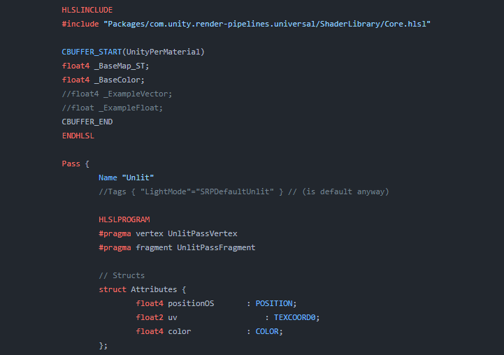
Explains how shader code (ShaderLab & HLSL) is written to support the Universal RP
One example people starting out learning shader in Unity today is running into old code using the UnityObjectToClipPos(positionOS) function.
This was the old Built-In RenderPipeline for getting the object space and turning them to clip space.
It is replaced by TransformObjectToHClip(positionOS).
Due note you can also use GetVertexPositionInputs().positionCS.
GetVertexPositionInputs is a bloody nice helper function with built in one word conversion from any types of space to another.
Object to world, world to clip, and so forth.
I dont really plan on writing in URP
I should of said more like any Scriptable Render Pipeline. So HDRP, URP, or 2D rendering.
Built in render pipeline is pretty much the only thing not using HLSL now days.
ah... so i should use URP? im confused now
It seems that the only thing missing was _ADDITIONAL_LIGHT_SHADOWS, I just forgot the S at the end xdd
What render pipeline are you using for your project?
Just for reference, not sure how much expierence you have working with Unity's rendering so sorry if I might state something you already know, Unity has a few render pipelines that you can choose from.
The old render pipeline is called BIRP (Built-In Render Pipeline) when users only had one option.
Now you have a few options. Due note all the new options work with HLSL, so write HLSl shader once and it can mostly copy to other render pipelines.
You have a render pipeline for 2D games because back than Unity didn't have on, so 2D lighting/shadows was not a thing.
Univerisal Render Pipeline used supporting the most platforms as possible hence it's name. If you need a lot of platforms that have a range of hardware specs like desktop and mobile devices, this one is your friend for 3D games.
High Definition Render Pipeline (HDRP) for higher end games needing better graphics like ocean rendering, dynamic sky lighting, water tools, and a lot more.
Due note all pipelines have the possibility for ocean, water, and dyanmic rendering. HDRP just has a built in tool already made for you.
ok.. i see...
ok, I am using the built-in VRC render pipeline, not the URP.
I think I should be ok as my unity project works with .shader and .cginc..
the shader I want to make will take a mesh, rotate it to some parameters, and use a stencil to create a spotlight effect with said mesh
fellas I dont understand the difference between screen space and clip space. Clip space is after the projection matrix right? When its converted to the frustrum, what exactly is screen space
what happens in between screen to clip space
Perspective divide, and some remapping
What exactly does that mean
what are they trying to do from clip space to screen space physically
Due to the way the projection matrix is set up, it outputs homogeneous coords. Meaning it has an extra fourth component (usually labelled w), which is equivalent to the eye-space depth to the fragment for a perspective projection, and just 1 for orthographic.
In between clip space and screen, it divides the xyz components by the w. That applies the perspective effect, making distance objects smaller on the screen.
Can probably google around for more info & explanations with images which might help clarify further
ok, I guess Ive misunderstood clip space then. I assumed clip space was the one that normalized the co-ordinates, instead of the one operation that ensures it lies between (-w to w)
If the screen space is what results after it goes through normalization I understand what it is now
To be specific as well, functions like ComputeScreenPos is typically handled in the vertex shader and does the remapping part of the clip->screen conversion (into a 0 to w range). The output isn't exactly in "screen space" until doing the pos.xy/pos.w, usually in the fragment shader
Also one more thing
Is there a place where I can look up available HLSL functions for unity
Depends on the render pipeline. For Built-in RP there's some docs, e.g. https://docs.unity3d.com/Manual/SL-BuiltinFunctions.html
Can also download the built-in shader source from unity's site (e.g. to see what functions UnityCG.cginc actually contains)
For URP/HDRP you mostly need to look under the ShaderLibrary folder in the package
HLSL itself also defines basic functions, which is documented here https://learn.microsoft.com/en-us/windows/win32/direct3dhlsl/dx-graphics-hlsl-intrinsic-functions
alright gotcha
I have a fullscreen shader applied via RendererFeature, it's working fine but I can't get it to interact properly with transparent materials.
Write Depth is ON, the injection point is set to "before transparent", but I can't find what's wrong. Transparent stuff write fully over it no matter the actual distance, even when setting the depth value in Shadergraph manually to 0 or 1 (using Linear01).
If the fullscreen pass occurs in the "before transparents" event, transparent objects are always going to render over it
Shouldn't they be able to read the Depth Write from it?
float depth = SHADERGRAPH_SAMPLE_SCENE_DEPTH(UV + sobelSamplePoints[i] * Thickness);
I am new to shader coding , not sure how to filter out some objects off the passed depth in this hlsl function used in shader graph (urp)
also tutorial links would be appreciated
does anyone know any good per-object outline packages or any documentation on how to make one?
biggest issue im trying to solve rn is having the outline not be in front of objects that are in front of it
literally every outline system i've tried on github falls short on that one thing

Seems like just a ZTest would suffice here
Resulting in something like this

So kind of depends on how your outline works, but if it's a 'render silhouette -> dilate silhouette -> composite outline' type of outline, then just add the appropriate ZTest.
case Occlusion.Always:
silhouette.SetFloat(CommonShaderPropertyId.ZTest, (float) CompareFunction.Always);
break;
case Occlusion.WhenOccluded:
silhouette.SetFloat(CommonShaderPropertyId.ZTest, (float) CompareFunction.Greater);
break;
case Occlusion.WhenNotOccluded:
silhouette.SetFloat(CommonShaderPropertyId.ZTest, (float) CompareFunction.LessEqual);
break;
https://youtu.be/jusWW2pPnA0?t=497
I am trying to replicate the fluffy trees from tiny glade.
There are LOTS of fluffy tree tutorials out there, but I looked at all of them and they skimp on the critical details that make it look and feel good.
Glade trees have a random rotation given to each quad face, how would you achieve that?

You can see the random rotation taking effect as the mesh swells up
been through tons of renditions, but i ended up finding this flood fill version from an article which does screen space (i think) stuff
mianly bc i need it to be 1px pixel perfect
so there's a bunch of stuff with stencil and all that, just trying to figure out the best way to do the masking there
does anyone have a clue as to why my wall shader is being stupid. using URP unlit transparent shader

ill send more pictures if need be
but i dont want to spam this channel unless someone can help
basically i can see through the wall to the other side of the wall and i can see my player through the wall.
I have a good shader which should act perfectly in terms of making my wall fade out where the camera is closer


is it set to transparent or cutout?
cutout is also known as alpha clip
alpha

try using alpha clipping instead
there is a node for dither too which is often good to use with such an effect
Transparent shaders do not (by default) write to the depth buffer
Transparent materials do get drawn from back to front, so this is not an issue for non-overlapping renderers
in this case, though, the renderers overlap
this means that some pixels will have been written to by something that is clearly closer to the camera than what's currently being rendered
but the engine has no clue about that
In this case, you definitely just want to switch to alpha clipping
you've already got a neat dithering effect
alpha clipping allows for an otherwise opaque shader to completely skip drawing to some pixels


You must make sure the changes to the graph are saved, and that the material is not overriding Surface Type since Allow Material Override allows that to happen
thanks
it worked
switched some things around got it working

thank you everyone who helped
Hey everyone! I'm trying to make an attack indicator system where it highlights the part of the ground that's inside a mesh, any tips on how to implement this?
i've implemented this several times now in various ways
i'm not sure i've ever done it "properly", ha
most recently, I did it by writing a shader that uses stencils
first, in a Cull Front pass, it marks all pixels that are behind the depth buffer. then, in a Cull Back pass, it clears all pixels that are behind the depth buffer
any pixels that remain marked get highlighted
i first did it with a shader graph in an HDRP game. that was a lot more mysterious
i went back and read it again and had no clue why it worked
The first step marks pixels that the shape is behind
the second step gets rid of those that the shape isn't in front
yeah, I did this in the past, until I realize that I can do the same using particle system
you might find this to be useful
float3x3 AngleAxis3x3(float angle, float3 axis)
{
    float c, s;
    sincos(angle, s, c);

    float t = 1 - c;
    float x = axis.x;
    float y = axis.y;
    float z = axis.z;

    return float3x3(
        t * x * x + c,      t * x * y - s * z,  t * x * z + s * y,
        t * x * y + s * z,  t * y * y + c,      t * y * z - s * x,
        t * x * z - s * y,  t * y * z + s * x,  t * z * z + c
    );
}
it computes a 3x3 matrix that performs a rotation
i forget where i nabbed this from
the rotation is not the hard part, the 'random' rotation amount is
i'd use something like https://www.shadertoy.com/view/4djSRW for the randomness
i love these functions; i use them everywhere
you'd use the center of the quad as the input to the hash function, then use the result to rotate the quad
(or you'd give each quad an ID, or something like that)
Hmm yeah thats the part that was throwing me off was how do I mark or ID each individual quad
I would like to keep doing the shader approach because it is more flexible for working dynamically on any mesh
rather than using particles or a baked mesh, I know cyan has a tutorial for flufty trees as well
Like every outline I can find has these big gaps if you try to make it wider, is there any way to make outlines that avoids that?

That'll happen with inverted hull outlines
fun fact: UV maps don't have to contain texture coordinates (:
they're just...floats
a very common thing I do is to bake an identifier into a UV channel
so if I have 500 little objects, I bake a unique ID for each object into UV1.x
and then shove the center of the object into UV1.yzw
(you can put up to four floats into each UV stream -- but you can only move X and Y from Blender to Unity, so using Z and W requires extra work)
i've gotta polish up my blender add-on and unity package for doing that
your model should not have sharp edges, you can try to override that by setting the Smoothness Source to none

What value ranges does it have?
I have no idea.
I'm trying to access these values from shader graph, so I want to know where they're being pumped into.
Assuming it's part of the vertex input struct, you could probably access it via a custom function node
Not entirely sure what you're doing or trying to do
I have this simple shader. I want to make the particle glow, so I thought it'd be a good idea to feed in some HDR color through the vertex streams to control that.

Since the base color control doesn't allow that.
Yes I know I can just make a regular emissive material, but idk. I thought it'd be useful to control that on a per particle system basis.
Might be easier with a separate buffer imho
No. A buffer that contains this color for every particle. Then just sample in a custom node function
Though, I'm not sure how easy it is to bind it to the right draw call,
I'm just confused because I've used vertex streams before. I brought these particles from an older project. I don't know what Instanced means in this case.
In terms of where the data is being stored on the mesh.
I think you can access it in a custom node function by the name. vertexInput.Custom1.
Ah, but the function is not gonna have access to the struct.
Did you try UV2 in the uv node?
Is it even there?
Wait if I swap the particle system material to the one I made, it fixes itself.
Before it was using a URP Particle Unlit mat.
How odd.
I mean, yeah. If the material was not using your shader, then obviously that wouldn't work.
I'm unclear if you could access any of this in the shader graph
I've recently written several ShaderLab shaders for instanced mesh particle systems
Unity provides a few functions you normally call in the vertex stage to set up the per-instance data
they modify things like unity_ObjectToWorld
They grab that data from a buffer
Each of the "INSTANCED" items in the list needs to correspond to a correctly-sized item in a struct
see the example on that page
The main thing I'm unclear about is whether you could include that #pragma instancing_options procedural:vertInstancingSetup directive
Okay obviously 😛 . But the vertex streams listed out INSTANCED but as soon as I swapped it to my material they swapped to TexCoord
So does "Instanced" mean "Hey bro there's nothing to put this into based on the given material".
Instanced rendering means that you send one gigantic blob of data to the GPU all at once
1000 matrices, 1000 colors, 1000 speeds, etc.
That requires some extra legwork
If you aren't doing instanced rendering, then that data will just go into extra texture coordinate streams
the particle system creates a large mesh every frame and sends that entire thing to the GPU
importantly, you just send one copy of the mesh
Alright that makes sense. So why is it that when I swapped materials, the instanced vertex streams swapped to Texcoord? Is it because texture coordinate streams became available?
I guess the particle system decides that your shader doesn't support instancing, so it falls back to the normal mode of operation
Either smooth the normals or use a different (screen space) technique
need help on a shader, happy to pay someone to finish - see thread for details
Swapped from which to what?
Hi all. I am creating a dissolve type of shader using the usual alpha cutoff techniques. However I want to avoid dissolve across the mesh and instead dissolve based on a growing circle. This I have done through some simple radius controls.
But when I add noise to make the cutout less like a uniform circle I end up cutting out pixels further away from circle edge. Has anyone got any advice on how to only add noise to the edge of radius cutout instead of the entire material?
It depend on how you blend the noise with the cutout edge.
If you consider the cutout like a gradient and the noise line an other one, something similar to an overlay blend (keep th 1 and 0 value of the cutout gradient, but noise the intermediate values) might be what you are looking for.
anyone know if there's anywhere that i can find more custom shader-graph nodes like this?

GitHub
Custom Nodes for Unity Shader Graph. Contribute to gilescoope/shader-graph-nodes development by creating an account on GitHub.
Has anyone ever made a soft occluder shader?
Like fading out object A with anothers object shader while hiding object b entirely?
How's this accomplished? The grass at the intersection

Like what in particular ? The is some wide variety of nodes on this github. What are you seraching for ?
Also, the shadergraph samples do contain quite some
"decals", either as projected decals, or just dedicated meshes with an alpha mask.
Do you have a particular fading method in mind ? Simple alpha fade or something more complex ?
How can i get a masked material reference to be able to modify properties? im doing this on a UI Image.
in code that is
Thank you @amber saffron
So the whole usecase is to mask out objects on specific spots in 3d space. For now I tested with spheremasks or similar. The purpose is to have some kind of soft occlusion on vision pro like the people awareness but the other way around, so real world objects (predefined positions) should be shown inside the digital world. But as the distances are quite large, we cant rely on the visionos build in occlusion resolution.
In the end I plan to create some kind of "cloud volume" as array that feeds that matrix mask into the shader and cuts out those parts, but thats like the top notch and result
Can you change the shader that object A is using?
if so, it's easy enough to clip out pixels that are too close to a world position
Yeh, there are two approaches I am researching. Everything is transparent shaders (not the best experience in z fights on AVP) and we can just clip with a mask/texture or having something like the standard occlusion material of Unity (which converst into realitykit materials), but instead of hard cut, have a soft fade
So I've been working on a pretty wacky shader for a VRChat avatar that does something in this ballpark
As the second option would need camera access (only for enterprise purposes available), I guess I have to stick to option one
My eyes and ears are wide open 😄
It cuts out chunks of the world and renders my own stuff in those spaces. I rewrite the depth buffer with the SV_Depth semantic.
you hate to get sent to the Optimized Box
(yes, this is Cyberpunk 2077-themed)
haha, nice effect
It figures out which parts to chop out by recovering a world-space position from the depth buffer
it it some kind of array or one position you check for?
It's one position
I'm working in VRChat so I have like
two tin cans and a string here
if you want to input additional positions into a shader, you have to add black non-important lights with a specific alpha value and then see if your light array contains it
it's great
This does not require cooperation from anything else in the scene. It also does normal opaque rendering, which is nice.
hm, wonder if I can use that on AVP.
If you badly need to punch a hole in the world to display something else, it might just be the way to go

we love to gaslight the GPU
I feel like you can do way, way more if you can actually write..you know, renderer features
and run scripts
😭
post process or camera access would be all i need, but no 😄
fixed4 frag(v2f i, inout float depthOut : SV_Depth) : SV_Target
{
    float3 worldPos = ClipToWorldPos(i.clipPos);

    i.clipPos /= i.clipPos.w;

    float4 grabPos = ComputeGrabScreenPos(i.clipPos);
    bool keep = CalculateCoverage(worldPos, grabPos);

    grabPos.xy /= grabPos.w;

    float raw_depth = SAMPLE_DEPTH_TEXTURE(_CameraDepthTexture, grabPos.xy);

    depthOut = raw_depth;

    if (!keep)
        discard;

    depthOut = LinearEyeDepthToOutDepth(10000);

    return 0;
}
that's the gist
CalculateCoverage decides if a pixel needs to be affected
oh yeah, and
inline float LinearEyeDepthToOutDepth(float z)
{
    return (1 - _ZBufferParams.w * z) / (_ZBufferParams.z * z);
}
copy-pasted from a bgolus post as god intended
something that I genuinely do not understand is why I need to pass the clip position as a TEXCOORD semantic to make this work right
the SV_POSITION input produces crazy results if you try to use it to calculate a grab pos
Thanks a lot for sharing that information! I def. need to dig more into custom shaders. The issue is, that unity to AVP is a hassle as unity will ocnvert everything to realitykit materials. So I gotta hope, the shaders stuff is working on the converted part too
oh yeah, that's a whole can of worms I know nothing about
Yeh, its cool they make it easy to build, but all those features you are waiting for unity to adapt are sometimes show stopping.
I had not once hack myself into the build xcode project to get features, that are in xcode but not in unity yet 😄
but thanks again, i will copy this over so I do not forget and check on your code 🙂
At the end, I read the camera depth texture and restore the depth buffer with it
(or just clobber it completely, so that transparent renderers don't show up)
i was seeing everyone's eye lens materials through the illusion, haha
haha, camera depth texture, yeh, nothing you get from apple rtight now unless you are enterprise which leads to 100+ employees and a lot of other stuff to fulfill
yeh but I need the real world one if I wanted to use depth information, which I am nt allowed to 😄
Hi all,
Soooo, I'm trying to build up a shader that fades with distance to camera.
It's all working, except for one thing, it looks like it's inverting my normals and I'm a bit baffled as to why (nothing to do with the mesh, it worked fine until I added this new section of the graph to the Alpha channel
Here is the graph, and the result at what supposed to be 100% opacity.
Could anyone point me in the right direction as to what I'm doing wrong please?


You can't solve this with alpha transparency. You need to implement dithering transparency emulation by utilizing only alpha test: https://danielilett.com/2020-04-19-tut5-5-urp-dither-transparency/

Daniel Ilett: Games | Shaders | Tutorials
Drawing objects with dithering patterns
Aaaah Gotcha, thank you.
Umm.....Okay, why does this happen when I change the surface type to Transparent? 😕
Texture has no alpha channel etc.

A Transparent material does not write to the depth buffer.
It doesn't matter that it's got an alpha of 1 (meaning that it completely replaces the contents of each pixel)
will pay someone $420 to complete this
#1341316131700609085 message
!collab
:loudspeaker: Collaborating and Job Posting
We do not accept job or collab posts on Discord.
Please, use Discussions to promote yourself as job-seeking, advertise commercial job offers, or look for non-commercial projects to participate in:
• Collaboration & Jobs
no matter what i try i cant get shaders to work on my 2d game
What is it that you tried?
Urp shaders
You have to be more specific about how you encounter the problem
Is there a way to change the Bayer pattern values to have less +s snd Xs and look more like the second image?


Thanks for the reply. That does sound like what I'm aiming for. Perhaps I am overthinking the solution here. Attempting to replicate something like this image. But unfortunately still not able to do so. In limiting the texture to the circle I end up with only minor cutouts along the edge.

Hey, absolute noob at shaders here, I'd like to create some sort of "corruption" effect that would be some sort of noise that slowly moves over the object providing pulsing dark spots and such, any idea what guides / tuts / references I could look up to do this? Other than "I might need noise and some way to move it" I'm pretty lost 😅