#archived-shaders
1 messages · Page 97 of 1
is a spherical one, im not sure if the noise is turned or the sphere itself
Hello, I have put together this shader here

for this effect,

But I cannot figure out how to get the distortion to encircle the disc entirely
It stays in the lower left quadrant regardless of camera position, rotation, etc.
I know it's related to the screen position node, if I invert colors there it does move but it also flips the distortion on the skybox, so thats no good
its a shader, the skybox its a spherical one
How is emission calculated? I'm trying to add it to my toon shader
Just add/set your emission color to the final value in the pixel shader.
so it's additive rather than multiplicative?
I presume that on the regular lit shaders, the emission settings are just ``value + (emission colour * multiplier)`?
Have you read that outline tutorial that was linked? It explains it.
Anyone could give some guidance on rendering a lot of transparent elements? As I am running out of ideas how it would be possible to achieve it. More details in this forum post.
Only idea left is to actually render as separate mesh each element in the list, but I don't think Unity can handle that many draw calls and game objects.
I was following a old guide about water shaders, up this point it was going okay, but the light. I am using HDRP, i think my scene color is over exposed, not sure where 2 begin.


trying to calculate how much an object should rotate on the y axis to always face the camera but not working correctly

also tried dot product between that normalized vector and (0,0,1) then arccosine but same problem
the problem is it only updates the angle when there is a big difference and overshoots the rotation about 90° or a bit less
Yes. But probably without multiplier. It's probably something like max(litColor, emissionColor). Might be a bit different if taking hdr colors into account.
I found out that I can just set the emission colour field to be HDR in the inspector. Plus the standard URP 'Lit' shader also just has a bool to enable/disable emission as well
so I think that all I need is 'existing value + emission colour' and a bool that only adds on the emission value if it's enabled
Not sure about addition. I think the standard behaviour is that it overwrites the calculated lit color if emission is stronger. At least if I remember correctly how it works. You can test it out with a standard shader and see for yourself.
@kind juniper I guess I'll give it a try later, thanks mate
currently I need to diagnose my thermal vision overlay's dodgy performance, I think it might be because I'm fetching a command buffer from the pool and releasing it every frame, instead of just keeping the same one
How do you set a GraphicsBuffer on a material when using CommandBuffer?

Is there a way to set it on the material directly though?
I don't really understand the difference between global buffer and non global buffer.
Is global buffer worse for performance?
You can set it on the material, but not with a command buffer.
On lower level, there are no materials. Once you bind a buffer, it's gonna be used for the next draw call. That's what it means to be global I think.
It's not worse for performance material buffers are bound in the same way.
Setting a buffer on material would just bind it to the specific material instance. That's the only difference.
Yeah that's what I was trying to do. I thought global buffer would be worse since it binds it to all shaders.
It is technically, it depends on what shader you set for the next draw call.
Why would that matter if it's global?
I think global is just bad wording here. What they mean is that it's not related to any particular material.
Also, perhaps because if you add more draw calls to the command buffer, they all are gonna have that buffer bound. Until you override or unbind it.
That makes more sense, how do you unbind it? Call SetGlobalBuffer and pass null?
You can do that. But usually you either override it with a different buffer(if it has the same name), or leave it as is.
Modifying the GPU state costs performance, so it's cheaper to just leave it as is instead of setting null or something. Though, in this case, the difference is probably negligible
I have a custom Scriptable RP that uses the Vulkan render passes for deferred rendering, but sometimes I have random stretched triangle artifacts that appear on the screen for a single frame. To investigate I opened frame debugger and saw that every render target is flickering.

I noticed that if there is a scene view and game view the flicker is between 3 "TempBuffer x" and if I hide one of them its between 2 and if I hide both its only a single blank buffer.
Sounds like tripple buffering issue? Do you know what that render target is used for?
So I had this code in OnPostRender attached to the camera, but I'm trying to move it into a render pass of HDRP.
_lineMaterial.SetPass(0);
_lineMaterial.SetBuffer("lineBuffer", LinesManager.lineBuffer);
Graphics.DrawProceduralNow(MeshTopology.Lines, LinesManager.lineCount * 2);
I have this code in the render pass, but the lines are not drawing correctly. The positions appear to be wrong.
ctx.cmd.SetGlobalBuffer("lineBuffer", LinesManager.lineBuffer);
ctx.cmd.DrawProcedural(LinesManager.lineBuffer, Matrix4x4.identity, _lineMaterial, 0, MeshTopology.Lines, LinesManager.lineCount * 2);
What shader are you using in the material?
A custom shader I wrote (with help from Rukhanka), It works in when using the first approach.
struct LineData
{
    float3 startPos;
    float3 endPos;
    float4 color;
};

struct v2f
{
    float4 pos : SV_POSITION;
    float4 color : COLOR;
};

StructuredBuffer<LineData> lineBuffer;

v2f vert (uint id : SV_VertexID)
{
    v2f o;

    uint lineId = id >> 1;
    LineData ld = lineBuffer[lineId];

    bool isEndPoint = id & 1;

    float3 vertexPos = ld.startPos;

    if (isEndPoint)
    {
        vertexPos = ld.endPos;
    }

    o.pos = UnityObjectToClipPos(vertexPos);
    o.color = ld.color;
    return o;
}

fixed4 frag (v2f i) : SV_Target
{
    return i.color;
}


Well, you'll need to debug it.
I can only guess that either the buffer contains invalid positions or the matrix is incorrect. Perhaps identity matrix is not correct for default transformation? Never touched on matrices. Or perhaps there's some parameters missing that get bound during DrawProceduralNow but not if you use command buffer?
Something that unity uses in UnityObjectToClipPos
Like a camera matrix or something
I'll keep digging, thanks for the suggestions. They are world positions so I thought identity is correct, but maybe not.
Any idea why my assigned texture in a custom shader that I have, doesn't match what is displayed? seems like a UV issue to me. That multiply in shadergraph goes directly to color on the fragment shader


no messing around with the vertex part of the shader
I'm setting the texture via material.settexture
can you explain, what canvas object you are setting the material at?
it's an overlay canvas, if that's what you're asking?
no, on what component do you set the material
is it an image component?
custom component
tried it with an image yet? to be sure its the shader and not your custom comp?
it works 100% when the shader is set to unlit
yeh, i mean you can just ignore my suggestion 😄
the component generates a custom mesh in OnPopulateMesh, and disabling it does indeed fix the problem I guess...
Does your mesh have uvs assigned?
I can see uvs being assigned, but it's not my code and it's pretty complicated so I struggle to figure out if they're correct
I would guess, they are not, as the texture is strechted weirdly
I fixed the UV issue, but it seems like setting the texture destroys the UV... somehow
I have, for testing, set it up so that it renders just the UV, and it's correct, but on the objects where a texture is set, it renders a black image instead of the UV
the texture is set on the images above, but the image below doesn't have a texture set

Make sure that the images are still using the material you expect. I know that Unity will swap out the material if any masks are being used
it does some evil stuff to support masking
oh my god the issue was that there was a canvas somewhere up the parent tree that had "additional shader channels" as everything and one of the channels broke everything
ah, that would make sense
I'm not sure how that actually works, but I've had similar breakages with particle systems where my vertex data layout didn't match up with what the shader expected
Would be nice to know what was the issue when you figure it out.
I was at physical therapy, about to dig into it again. Will update here once I figure it out.
@warm pulsar im sorry for ping but i just came back on pc, should i upgrade to 2023, or is there any better versions?
cause i dont feel like upgrading to 2023 just to find out there is one feature later that i would need 😭
also im kinda low on space would it be alright?

you can certainly give it a try -- you'd upgrade to the latest Unity 6 LTS release
I would try to get a little more room.
Make sure you have a backup of the project, of course
you mean get more space?
cause if i get lower than 20 my pc doesnt work 😭
Yes.
If you have old projects you aren't actively working on, deleting their Library folders can free up a lot of space
(and, notably, your project backup can exclude the Library)
how much would i need to update from 2021 to Unity 6
like if 2021 is 10 gb
how much is unity 6
this is the best i could do

all of my projects are on another drive
i only have programs here
That should be enough space
also im installing it on d drive
im just saying like the program files if that would exceed 12gb

shouldn't be much of a difference in size
also 1 more question
i already have vs code and vs
i unchecked this

all will be good right?
yes
okay thank you
Going back to my problem from earlier, I have tried passing the view projection matrix manually to my shader like so.
Matrix4x4 vpMatrix = ctx.hdCamera.camera.projectionMatrix * ctx.hdCamera.camera.worldToCameraMatrix;
cmd.SetGlobalMatrix("_ViewProjMatrix", vpMatrix);
cmd.SetGlobalBuffer("lineBuffer", LinesManager.lineBuffer);
cmd.DrawProcedural(LinesManager.lineBuffer, Matrix4x4.identity, _lineMaterial, 1, MeshTopology.Lines, LinesManager.lineCount * 2);
I created a second pass in the shader,
struct LineData
{
    float3 startPos;
    float3 endPos;
    float4 color;
};

struct v2f
{
    float4 pos : SV_POSITION;
    float4 color : COLOR;
};

float4x4 _ViewProjMatrix;
StructuredBuffer<LineData> lineBuffer;

float4 WorldToClipPos(float4 pos)
{
    return mul(_ViewProjMatrix, pos);
}

float4 WorldToClipPos(float3 pos)
{
    return WorldToClipPos(float4(pos, 1.0));
}


v2f vert (uint id : SV_VertexID)
{
    v2f o;

    uint lineId = id >> 1;
    LineData ld = lineBuffer[lineId];

    bool isEndPoint = id & 1;

    float3 vertexPos = ld.startPos;

    if (isEndPoint)
    {
        vertexPos = ld.endPos;
    }

    o.pos = WorldToClipPos(vertexPos);
    o.color = ld.color;
    return o;
}
My math must be wrong somewhere.

Okay I figured out the problem and it kind of makes sense now.
I was doing this which was not working:
cmd.SetGlobalBuffer("lineBuffer", LinesManager.lineBuffer);
cmd.DrawProcedural(LinesManager.lineBuffer, Matrix4x4.identity, _lineMaterial, 0, MeshTopology.Lines, LinesManager.lineCount * 2);
And this is what works:
cmd.SetGlobalBuffer("lineBuffer", LinesManager.lineBuffer);
cmd.DrawProcedural(Matrix4x4.identity, _lineMaterial, 0, MeshTopology.Lines, LinesManager.lineCount * 2);
So I guess I was incorrectly using the wrong overload
and shouldn't pass the buffer in cmd.DrawProcedural
I don't know what the use case for that overload is, but it is working now nonetheless.
yo bro should i still talk about the unity instalation here 😭??? i have a error....
i will go to unity talk
I'm not a mod so idk, but probably not
hey, any attempt to use the .Gather() hlsl function in my shader results in this error:
cannot map expression to ps_4_0 instruction set at [line where I use the function] (on d3d11)
any way I could fix this?
I don't really know if this is achieved in HDRP or URP, if it's a post-processing or a shader. But I was curious if anybody knew how to replicate a shader like so: https://www.youtube.com/watch?v=ZsMHY4LDyRE&ab_channel=t3ssel8r
Currently I'm using Unity's toon shader, which I really like! But I would like to get towards something a bit more pixelated in 3D.

Date of Recording: 2021-01-22
It's been a while since the last update from before the holidays. Several things have been in the works, including a fairly involved procedural terrain generator that deserves its own explanation video some day. Here we are showing off the improvement to the main pixel art shader including light-aware edge colorati...
total shot in the dark, but do you need to include a #pragma directive for the minimum shader level?
I'm not sure what Gather you're talking about here -- if it's the one Texture2D, that requires Shader Model 4.1
and ps_4_0 is 4.0
That would be my guess as well
I thought this was going to be a compute shader thing at first
(which would probably demand Shader Model 5.0)
I had mine set as #pragma target 3.5, my bad
changing it doesnt fix it as the function is in a separate script, hm
It is probably a full screen shader that reduces the resolution / applies filters, not sure exactly how it is achieved though
You'd need to put the directive in the actual .shader file
alternatively, there is #include_with_pragmas. I guess that'd wind up respecting the #pragma directive in the included file
I don't know how that works out (especially if you declare multiple versions)
That sounds complicated. 😂 I'll try search for tutorials that reduce resolution / apply filters or full screen shaders in general then.
This can be achieved with shader graph as well, with same concepts
that fixed it, thank you
I had my pragma target as part of the base .shader file and my function was in a separate hlsl file
still new enough to this that I didnt realize I could just set the target in the separate hlsl file
how would one recreate this property on the standard BIRP shader?

i'm building a flash effect over standard shader properties
so need to recreate some things
ah i mean how would i create that property in my shader graph?
oh, keyword enum?
SmoothnessTextureChannel
looks like
What are you looking at right now?
"Source"
That will correspond to creating an enum keyword property in your shader graph
yeah one of those

it looks like
huh, it seems to have converted to the correct property name automatically when i put in _SmoothnessTextureChannel

just wild guess but the dropdown wont appear in my shader settings
"Predefined" is incorrect
that's used for a keyword that can't change
you want "Shader Feature" here.
oh i thought it was referring to a property that is known by the engine
no, there's nothing special about this name
Note that you can really just leave this out entirely
unless you genuinely need to be able to configure where the smoothness comes from
is it metallic alpha by default i'd assume?
hm, this produces very different results from the standard shader

standard

my shader

Your shader is not using the alpha of the metallic map.
It's just using a constant value for smoothness
Correct.
oh
yea there it goes
curious why the smoothness float on the standard seems to affect it though
or is it multiplying?
It multiplies the slider with the value it got from the metallic map, yes
aha
ok last question i think, since i just went through all the math nodes and every variation of blend. if i want to just straight up overwrite the whole surface with Color x Fade Time, is there a proper node for that?
basically at 1.0 it should just appear all (color)
I'd use the Lerp node to blend between the original albedo color and the solid color
you'll also want to add some emission
yeah the color is hdr too
lerp is linear interpolation
basically just (1 - t) * a + t * b
hmk
Note that the albedo color is not a high dynamic range color -- it'll only take values in the 0..1 range
But emission can go arbitrarily high
yeah i mean it works sort of
(It wouldn't make sense for albedo to go past 1 -- that would mean that the surface reflects more light than a perfectly white object)
it needs a significant intensity level to flush it out
its getting the same result as the Overwrite blend style
i don't use the blend node much, so I'm not sure how that'll work
i guess thats not quite what i was going for but itll do
i wonder if i just set the texture alpha inverse to the fade time
what are you actually trying to accomplish here?
flush the entire mesh with the color at fade time = 1.0, and show the standard texture at 0, and blend between them in between
like when you get hit in a game and your character flashes a color
thats what im going for
i tried that, didn't quite work


ah, yeah, you'll still be getting normal lighting on the object
it looks like it should be working according to the lerp node preview but it doesn't appear to be flushing it out
so you'll see dark areas and shiny areas
Consider doing the following:
- Lerp the albedo to black
- Lerp the smoothness to 0
- Lerp the emission from black to the fill color
is there a node that could reduce its light receiving property?
i could tie it inversely to fade time
you could also go ahead and lerp the Ambient Occlusion value to 0
That will prevent ambient light from showing up at all
hmk
unfortunately you can't just say "The color is exactly X", because you're just telling unity about some material properties
ah... yeah this web is getting tangled and not really getting results
it is possible to hand-write a shader where you can do both "exactly this color" and "actual lighting", but not in the shader graph
i think
just having the hdr flash was fine
it get sthe job done with a certain intensity level
A bright emission will wash out everything else pretty well
yea good enough for now i dont wanna get too hung up on this rn
make the albedo color black as well


one important thing -- if the color is really intense (say, [16, 16, 16]), then you'll only need to slightly blend it with the original albedo to get white
That will make the albedo go to white super quickly
yeah this was very enlightening thanks
I'd just set the base color to black while flashing
so, instead of using your Color input, use black
also, it looks like you've wound up double-counting the fade time
you're multiplying it with the color and then using it to lerp to the resulting color later
you can just lerp between the original albedo and black
i was having it subtract the albedo towards black as the float goes from 0 to 1
oh hm
more like this then?

i think we're not getting around the lightning influencing it
plug this directly into the Base Color node

base color goes to black; emission goes to white

although with the color being white it does seem to get better results without as much intensity required
actually yeah i just need to tweak the emission color but thats better
red result 1.0 intensity~

white at 2.0

its more responsive either way
at'll do thanks so much for your time
Anyone recommend a good shader to have walls show a hole to see through it to your player / target?
how can i stop the texture from stretching around the edges? (offscreen stuff is just rotation)

The stretching in the preview is probably due to how the default sphere is uv unwrapped/mapped.
Ah, you're using object position for uvs..? That might be the problem. Thing of what values it would have at points close to the poles.
You might need to use triplanar mapping for it to work
is there a way to detect if a shader is being rendered in the shader graph final preview (+ inspector/project tab preview)
cause from digging online ive found a property called SHADERGRAPH_PREVIEW
however when hooking it up to a shader graph using a custom function, it returns false in the final preview
yet it returns properly in the node preview and ingame
void IsPreview_float(out bool IsPreview)
{
    #ifndef SHADERGRAPH_PREVIEW
    IsPreview = false;
    #else
    IsPreview = true;
    #endif
}
- game
- scene
- node preview
- shader graph preview
- material preview


(black is false, white is true)
how to get the rotation of the object in your shader ?
I am using shader graph and object node only has position and scale
You can create a vector3 input, which the value of can be set in a C# script

well I wanted it to work without being tied to a script for every material of this shader
thought about transformation matrix but not sure how to use it
As long as the object with the material also has a component which does youMaterial.SetVector("_myPos", yourVector3); that's the most straightforward way to set it
Shadergraph is pretty limited with what it can really do, writing actual code (whether C# or custom HLSL functions) is sometimes a necessary evil
managed to fix it (with chatgpt 💀 ) but its really complicated
all of that just to rotate the mesh with the object as I wanted to make a shader that affects the whole mesh rotation

You typically don't do that on the GPU as it's a waste of compute, since you do that for every vertex/pixel.
What's the goal of that shader anyway?
snapping the position and rotation of the mesh to mimic the effect of cartoon/anime as if it's moving in a lower fps
looked weird when snapped every vertex independently so used object position then snapped it then calculate each vertex position relative to snapped origin but it stopped rotating so added what in the screenshot to rotate , will try add snappiness to the applied rotation
would be better if I can control when vertex position should or shouldn't be updated
Writing actual code is really the easiest way to go about something like this
t:material shader:Universal Render Pipeline/Lit"
i want to search for materials that are lit , how can i do this in editor ?
this doesnt seem to work
can anyone let me know how this works?
Shaders are very bad at remembering things.
You cannot get information like "where was this vertex one frame ago?"
(without it being provided via scripting, at least)
Hi everybody. First time writing in this Discord. I need some help: I have a shader that have some strange kind of "motion blur" that I don't want.


p.s.: When I rotate the stone or I switch off post processing on camera, there is no problem. it only show up when I orbit my camera.
Can you try switching the anti-aliasing mode? That's going to be a property of your camera
i wonder if this is TAA going haywire
There is no anti-aliasing. Both in camera and in URP settings.


Do you have both the HDRP and URP packages installed?
I noticed you had an "HDRP" section under the Quality setetings
it does look like you're currently using URP, though
I would try turning off the upscaling -- set the render scale to 1 and switch the filter to something else (note the warning about it not working mobile)
this is in the URP asset, which is in your second screenshot, in the "Quality" subsection
Resolved. It was the upscaling filter😂 . Thank you so much❤️
Hello there ! Nothing crazy here but I'm struggling to understand how the culling works here. My Alpha is set to 1 (so the result should be similar as an opaque object) but some (not every) backfaces are culled after the front ones. Is there a way to fix this and make it work properly with the alpha ? 🤔
thanks in advance !


Every face is being drawn -- but because this is a transparent shader, there is no depth information
If face A draws before face B, face B will always render on top of it
even if face A should be in front
Hello. I need help with this texture. I want to make it double sided using Free Double Sided Shaders asset from the asset store. But could not get past this poing. What is happening here?


Youl'll see different results as you rotate the cube
See if there's an option for a "Cutout" rendering mode
I chose the Cutout and its like this now

where did you choose that?
Also the image has transparency.
Yup, that was my thought (even if I don't understand if tehre's a logic about how faces are told "Oh this one is face A, this one is face B"). And is there a way to make it work properly ?
Show me where you chose that.
Not really! Transparent rendering sucks (see us complaining about in real-time in #archived-urp , haha)


Well, thanks for help then, I'll join your complaining club ahah
one thing that sticks out is that your base color has an alpha of zero

notice the black bar at the bottom
The alpha of the texture gets combined with the alpha of the base color (presumably, at least)
Its maxed now and still the same.
If you switch to the Standard shader and put it on Cutout mode, does it look correct?
(just not double-sided, obviously)
It works as you said yes. Not double sided though.
hm, maybe there's a setting you need to change on the double-sided shader, then
Can you share the entire inspector for the material?
The double sided?
Yes.


ah, try ticking "Use BaseColor Alpha"
it looks like the shader expects you to provide a separate map otherwise
I checked it and its like this now

anybody knows if it's possible using the frame debugger, render graph viewer, or some other tool to display what's in a given structuredbuffer for a given frame / pass in that frame?
Note that alpha clipping is all-or-nothing. Every pixel is either drawn opaquely or skipped
Since your texture is a bit blocky (I presume you set it to use Point filtering deliberately), the edges will be rough
You could use a separate cutout mask that's set to do bilinear filtering
Yeah I've done that on purpose.
also, i'd turn down the specular intensity and the smoothness
i suspect that's why it looks washed-out
It doesnt do anything when I play with the sliders. For both smoothness and specular intensity
Oh wait

It looks like this after dragging specular to 0 but smoothness does not have any affect.
I'm a little fuzzy on the specular workflow
But yeah, that looks nicer
You were getting a reflection of the skybox (which I presume is solid gray)
Skybox is not solid gray. We dont have that white part at all in our original texture. Not as this much at least.
@warm pulsar Sorry for pinging you but I forgot to say thanks. I messed with some sliders and got the look I wanted.
using unity low level graphics API, Graphics.RenderMeshInstanced, we can provide our custom struct as long as it contains an objectToWorld matrix. From the shader, how do I access the additional per-instance data passed via the method call?
@sharp radish @warm pulsar Assuming the other side of the plane does not look "washed out" it happens because of Double Sided option, and appears the same way with metallic workflow
I believe that's because the normal still remains inverted so it always produces the maximum fresnel value if not more
Hm, that'd make sense
I know that Poiyomi Toon has an option to flip normals on backfaces
probably for that exact reason
Likely, and that helps with outlines too
I guess the other option would be for the shader to mirror fresnel and other view to normal calculations across the halfway point
Oh okay. I'll take a look. It looks the same from both sides though.
Ah yeah I did that. Specular all the way to zero.
If you put those sliders back up, do the two sides wind up looking different?
Use SV_InstanceID semantic to declare system generated instance id of rendered mesh in shader. Then use this ID to index into your array.
Or Unity has unity_InstanceID
@frigid jay thank you!

ah, you're editing the original material asset
when you access the .material property of a renderer, a copy of the material is made
Changing the original asset will not do anything to that particular renderer
(until you exit play mode and re-enter, at which point the asset gets copied again)
You can use .sharedMaterial to avoid this duplication. Note that this means that changing the shared material will change the material asset, which is often unwanted
uhm, i go play, go into the object, double click the material, and if i change it still doesnt update


You're not in play mode here
so the game view might not update reliably
i know but right now i am
wait a sec
@warm pulsar here
ah, and here's the other thing
unity does some weird stuff to support UI masking
it creates a new material and uses it instead of the original when rendering the image
so i wont be able to change the colors from script?
I think you just need to grab materialForRendering from the Image (instead of material)
This is a property of the Graphic class, which has different behaviors from Renderer
i'm a little fuzzy on that -- i remember running into this issue before
but i don't recall what i did about it
looking at my existing code, I just use Image.material -- I don't think any masking is involved
I can tell masking happened here because the name changed

no idea 😭
when i get to scripting it, i could update you on what works and what doesnt if u want
The main thing I'm unsure about is whether the newly-created material is shared amongst many images
a snippet from my "radial arc" menu's code:
        private void Awake()
        {
            arc.material = Instantiate(arc.material);
            HighlightOff();
        }
clearly that needed to have a unique copy made
I wonder if it'll fall apart if I add a mask to the same canvas..
i dont need to update all the images at the same time, each individual is my scope
right, so you might need to do something like this (or else every image will share a single material)
my shader falls apart if i delete mask
I'm not sure what happens when it creates the new material, actually
i meant to say delete **
i will see, im right now making the UI for it lol
whether it uses one material for every image, or if every image gets its own instance


Is there a such thing as a hair shader? If there is I need it I tried looking for some for vrchat to make it look like this on the left but my outcome was the right.


have you tried anything with matcaps or any shaders that can mimic subsurface scattering, or maybe a shader with a modified specular?
I was going to try matcaps, not good with them and trying to find a matcap mask that would look good. I been messing with poiyomis Anisotropics
poyomi has a pretty good shader so I would just mess around with some more and it'll look good eventually
Yeah I'll do that. Thank you, I also just downloaded a shader called Alloy, so I'll mess with that aswell.
@fast igloo
never heard of alloy, tell me if its any good
also if you want more anime style hair a suprisingly good way to do that is just with an angel ring matcap
works on quest too bc its just vrc matcap lit for the hair
I'm trying to convert Sebastian Lague's Slice shader from his Portal tutorial to Shadergraph and I’m having trouble getting it to work properly.
Here's the shader I'm trying to convert.
https://raw.githubusercontent.com/SebLague/Portals/refs/heads/master/Assets/Scripts/Core/Shaders/Slice.shader
Here's my shadergraph.

Currently, the slicing works however it slices in the wrong area when passing through portals.
I have to be missing something because the code itself that interacts with the shader is untouched and I confirmed that this shadergraph variant doesn't work in the original codebase.

In the shadergraph, where am I going wrong? I'm mainly been adjusting the order of the math nodes. The current screenshot is what I got from adjust the order of the math which at least gives me something.
i'm not sure this is solvable so thought i'd ask here for input
i modified the sprite shader, adding a shadow pass, so that it would render a shadow
       Pass {
           Name "ShadowCaster"
           Tags {
               "LightMode"="ShadowCaster"
           }

           ZWrite On
           ZTest LEqual
           ColorMask 0

           CGPROGRAM
           #pragma vertex ShadowVert
           #pragma fragment ShadowFrag
           #pragma multi_compile_shadowcaster
           #include "UnityCG.cginc"

           struct v2f {
               V2F_SHADOW_CASTER;
           };

           v2f ShadowVert(appdata_full v) {
               v2f o;
               TRANSFER_SHADOW_CASTER(o)
               return o;
           }

           float4 ShadowFrag(v2f i) : SV_Target {
               return 0;
           }
           ENDCG
       }
thing is, my sprite has some perspective drawn into it
is there a way i can adjust the shader to get the right result?

(and if it's really unsolvable, what technique could i use for "fake" shadows)
It is unsolvable. You could use a custom prerendered shadow and render it with a sprite renderer that would follow the object.
Is there any practical difference between combining then lerping, versus lerping then combining? E.g. in terms of performance? I mean the difference is probably negligible, but I'm trying to learn stuff and grasp the inner workings

also the third option, which I'm pretty sure is the most performant out of all of them

Actually, a more important question in terms of actually achieving stuff: How would I go about overriding just one part of a shader, but not the other part? E.g. overriding the fragment phase but not the vertex phase?
I'm not sure that's achievable with shader graph.
If you have hlsl code, you could just use keywords/defines to define different versions of a shader. Or if you have access to the low level rendering api, you can specify vertex and pixel shaders that you want to bind to the next draw call manually.
I've created a shader following a youtube tuturial for a forcefield. I got it to look good in the preview and on the material in the assets panel, however when I bring it to an object in game it loses all of its color and brightness.
Any ideas?


How does it work?
Offscreen on left in a time input.

So I was able to get it show the colors in game, but only after I removed my directional light from the scene.
I think, perhaps it's because you're using emission and transparency. You can't make color brighter than white, so adding whatever color is outputted doesn't change the final color.
Just a guess
What blending mode are you using?
I believe its Alpha.
Maybe try additive
But there's probably not gonna be much difference, unless you're using hdr colors
Using Additive caused the whole thing to become almost invisible.

In URP, can I somehow perform stencil ops with the low level graphics API and a shadergraph shader? Since it's not meshrenderers via the standard render flow, I'm under the impression I can't use renderer features for stencil ops.
The idea is I have a GPU trail of meshes with fading transparency. They're rendered front to back, they overlap significantly to form something that ressembles a smoothed mesh. I want to discard all fragments that overlap for a gradual fading effect.
Yeah. Probably no hdr colors enabled
I am using HDR for colors.

@glad jetty What RP?
HDRP
Do you have them enabled in the urp settings and camera?
Ah, hdrp. Then it should be enabled by default I think
I guess alpha blending is the correct one.
I'd maybe check the alpha values that you get

That's a bit different though... Does it change anything?
Can't do it in shader graph. But you can modify the generated shader code and use that instead.
Not a thing. I am modify the shader not to multiply the final output by a float variable. I'll see if doing that helps.
Try plugging your alpha output into color or emission and setting alpha to 1 to see visually the value range
Well, I can see it now. Seems like something is causing the color to wash out.

Let me give this a shot.
Bloom
I wonder if you're getting some negative values here
I'd check the different noise/effect nodes you're using and see what value ranges they output
So, disabling the directional light for the scene causes it to look correct.

Maybe your directional light is super bright
Also, for such effect it might be easier to use an unlit graph. This one is lit, right?
It is lit
Is there a reason it needs to be lit?
I just followed the tutorial 🙂 I am VERY new to unity.
Can I put shader assembly(dxbc) into a ShaderLab(URP/HLSL) file?
I tried unlit as well with no luck.
If I adjust the lux of the directional light, I can see it when it gets around the first line.

To be honest, I wouldn't use HDRP as a beginner. It's way more complex than URP and requires certain degree of understanding in how graphics and rendering works.
HDRP uses quite high light intensity values by default to mimic real life lighting.
What is happening here is that the emission color of the material is not high enough to be visible with the direct sun light.
The solution like dlich mentioned is to use an unlit shader, or to use the "emission node" between the color and emission output of the graph, with an "exposure weight" set to 0.
There is a node that tells you the current exposure adjustment of the camera
You can use this to exactly compensate for exposure
Ah, I forgot about the emission node.
that makes it even simpler

Hi i hope texture optimization fits in this channel
So having power of 2 sized texture is important to allow mipmapping. But my style is pixel art, with low res tex, filter Point, and mipmap off. Is there then any benefit in having POT tex size?
I'm not aware of any other reason to keep a power of two
Note that some formats also put constraints on the resolution
e.g. some require the resolution to be divisible by 4
I don't like how point lights don't get very bright as you get very close. The light should be super-intense right at the origin of the light, given how brightly-lit the whole wall is when I pull the light back.
I'm guessing I would need to change how light attentuation is calculated, but I'm a little unclear on what to do, exactly.
I see that AutoLight.cginc is sampling something called _LightTexture0 here:
#   define UNITY_LIGHT_ATTENUATION(destName, input, worldPos) \
        unityShadowCoord3 lightCoord = mul(unity_WorldToLight, unityShadowCoord4(worldPos, 1)).xyz; \
        fixed shadow = UNITY_SHADOW_ATTENUATION(input, worldPos); \
        fixed destName = tex2D(_LightTexture0, dot(lightCoord, lightCoord).rr).r * shadow;
#endif
Maybe I need to write my own version of this macro that samples the texture differently?


For comparison, here's a point light in an HDRP game. This is what I'm looking for.


the light is astonishingly bright when it's very very close to a surface
(and the first set of screenshots are from a BiRP project)
((and I'm doing forward rendering, if that matters))
well that's vaguely promising -- I just copied AutoLight.cginc and replaced the texture sample with a formula

and that's annoying: _LightTexture0's meaning changes depending on whether or not a cookie is being used!
the attenutation now lives in _LightTextureB0
This doesn't show up when I bake lighting, though. I imagine I have to go mess with something else.
Ah, that's configured elsewhere -- in the Progressive lightmapper
So nothing really matters in my shader! That's good (and bad) to know
It's a little annoying for the realtime light to not match the baked light, but I don't plan to use any mixed lights, so that's okay
and implementing proper inverse-square falloff in the shader looks plausible (but unnecessary)
Lightmapper defines its own light falloff
https://docs.unity3d.com/6000.0/Documentation/Manual/ProgressiveLightmapper-CustomFallOff.html
yeah, I got that working. It almost matches my inverse-square falloff I hacked into the shader
You should provide more info than that if you really need help.
It's not obvious what the problem is from that screenshot.
Fen, i have reached what i needed
just changing the color, doesnt update it. so yeah, doing the .material = instantiate works
sadly if i want to make it real time, i need to do instantiate every single time i update it, i dont think its the best way but it just doesnt work if i dont
Instantiate the material once, then grab .materialForRendering
That should work.
When you plug a new material into the material property, Unity makes a new material with the modified shader
and that material goes into materialForRendering
So the problem was that you were trying to modify the original material (which isn't the one being used)
Making a new copy every time meant that Unity was seeing a new material every frame and copying its values into the modified material
Bumping because has been buried. Just want to know where in my Shadergraph it's not matching up with the Slice part of the shader script I linked. The reason I'm doing this is because the original shader was built for Built-In RP so doesn't work with URP.
ohh okay thanks
yeah thats not a good idea lol
how do I use an object to effectivley illuminate an intersecting object?
Where any object that enters the area is lit up using a shader?
Ok Sorry, Because I have this problem on my WebGl build on Safari
on Chrome it looks good, while on Safari no. But I do not understand why all the other assets go and this no


this is the problem that does on Mac
These are some really blurry screenshots.
Is it the textures being white in some places? Is that the issue?
It could be a graphics API difference issue. Does it work if you build a standalone Mac build?
looks like zfighting. check if your model has two overlapping cloths
I dont use shadergraph often, but shouldnt this be flipped?

like currently its
float3 offsetToSliceCentre = IN.worldPos - adjustedCentre;
not
float3 offsetToSliceCentre = adjustedCentre - IN.worldPos;
is it possible to import the textures from a blender model that uses slots into unity?
Like i've got a model with 5 different texture files for a single human body. Can unity import all of that?
No -- shaders are, generally, not portable between different programs
I believe some very basic shaders can get exported into an FBX (basically, blender can figure out that the base color and normal textures are being used)
I think thats what I originally had and it wouldn’t even do the slice however I’ll check when i get home.
In my screenshot, the swapped mathematics displayed a slice occurring which is where I left it. I’ll be home soon to try out your suggestion
so basically i've gotta make it all fit in one texture image?
that's fine then. I just wanna prototype for now anyway. Wasn't planning to use slots anyway but thanks that's helpful. I'll just put a checkerbox patter on the model i downloaded
Ah, right, the shader use clip(x) which discards the texel when x is below 0 (iirc)
your shader set the alpha threshold instead, thats why the inversion needed.
Maybe you should use fixed alpha threshold (like set it to 0 or 0.1) and multiply the alpha with the dot product instead (or the sign of the dot product)
if I get what you meant with texture slot right, yes, you can. you can have multiple materials for a single human body, like hair, eyes, head, and body.
Does anyone know a way to get sharp harp shadows without using shadow volumes? Because I tried to build shadow volumes from scratch once and it was a nightmare.

you can try hard shadow, but if the shadow res is low, you'll get blocky shadow instead 😅

I'm using hard shadows at max resolution and max cascades but it's still jaggy in places 

Is is possible to set a custom shadow resolution higher than the normal max? Nearly everything besides player and enemy shadows will be baked anyways so it should fine.
Think that's it!
Sign of the Dot product with a Threshold of 0 gave the best result.
There is some small bit of the model showing on the entry side of the portal but I care more that it slices at the centre like the original. Thanks for the help! Might just need to adjust the alpha threshold.
Now to graft it to the shaderpack I'm currently using,

Yes, but there is no other mesh, there is the skirt that is made with cloth simulation, and below it has the skeleton
Yes is this the problem
I should try it because the build was done in webgl

@candid pine I would try different platform specific texture compression formats for those particular textures in their import settings
And different graphics APIs for the build too as mentioned
hello everyone so I get this video result with my shader but I want the following seen in the images to happen instead but cannot do it so pls can someone guide me https://paste.ofcode.org/dK3C8DExGs5Wu3rJCGYFWH


I cannot tell what's exactly happening in the example images, but perhaps you want them in a sprite sheet and swap between with "flipbook" UV animation
no so basically the 56 * 56 sprite should be visualised in a 7 * 7 grid and then it should be reconstructed by forming a 3 * 3 grid a 5 * 5 grid and finally the original image
like this
So, the sprite is composed of 3x3 slices, and then reduced by removing/skipping those 3x3 rows and columns?
But in reverse to build it up instead
(Composed of 3x3 slices virtually, not as "sprite slices" in unity terms)
no the image is 56 * 56 and that in the game it is of 7 * 7 tiles due to limited gbc space I basically want to replicate that efect
here's the video if you slowly see it you can observe the gradual changes
Regardless of the exact slice size I assume I'm understanding right that the shrinked version of the sprite is made by skipping over odd or even rows and columns of the grid
I think the image is fragmented and not necessarily odd or even rows
Old games used to store sprites as smaller chunks, so this kind of effect was convenient to make
You say that solves it?
I'm not familiar with that issue but those are what I'd start tweaking first to see if they affect the issue at all to try to figure out what's causing it
And solve it, with luck
yup defenitely
yes, I hope to solve it too
If you don't want to make a flipbook animation for each sprite that only mimics the effect, a procedural option would probably work so that instead of UVs going linearly from 0 to 1, you'd have a math function that can skip repeating ranges
the flipbook animation would work for all of them but as I have multiple who have the same effect
Then make sure the ranges match the pixel grid, and to snap to multiple ranges for each stage of the animation
yeah I did that in the shader I attached but its not the effect I desire
Yes, it's not the right kind of "uv skipping", since you're only clipping out one end of the UV curve
then what should I use?
This is the kind of math function you need instead, first image would be linear UV and the second the skipped
Something that jumps ahead in the curve for each interval
But I don't know off the top of my head what that would be in math language


(also it'd have to be centered separately, and fit to the pixel grid)
I think it should be sin right
Might be as simple as adding another linear curve to it that's stepped or "posterized"
tried this but no luck https://paste.ofcode.org/547e9hHfH6pmhwggjjbYJf
got this

I would use a higher resolution test image to see exactly what's going on
The few pixels make it hard to see if it was successful or not


Yes, I think that's clear
But it won't look like that before you have the right method, and also the exact right variables for it
can someone please tell me why materials of this shader is getting lit by spot light in editor but not in build ?
and I can't seem to figure it out
!code

Posting code
📃 Large Code Blocks
Use links to services like:
https://paste.mod.gg/, https://hastebin.skyra.pw/, https://paste.ofcode.org/, https://paste.myst.rs/, https://scriptbin.xyz/
📃 Inline Code
Surround code with three backquotes. Not quotation marks.
To format as C#, add cs to the first line:
```cs
// Your code here
```
Add a comment with a line number if there is an error message.
First things first, make sure you're using the same quality settings both in the build and editor.
yes, and in accordance to that, the same spot light is working on all other shaders except this one
issue is only in build, in editor spot light making this shader lit too
Can you confirm what I asked? Take a screenshot of the quality settings tab.


Okay. What platform are you building for?
Windows
Okay. Are you setting graphics API priorities in the player settings?
Maybe just take a screenshot of the player settings where the graphics API option is.
this ?

Also, what renderer asset are you using?


should I give shadows and post process settings screenshot too ?
Hmm... These are unlikely to be related. Can you provide a screenshot of what it looks in the editor and build first?
ok
1st one is from editor and 2nd one is from build


hello?
That's extremely hard to discern.
Can you create a better comparison case? Like an empty scene with on object with the shader and a light source?
I tried linear posterization that doesn't result in any difference I think there is some other pattern
sure
hey Spazi isn't this the mosaic effect?
Yes, it can be used for that as well
what is the best way in your opinion?
First one is editor image second is from build


My idea seems to work, or at least be very close


yeah but in my version some uv needs to be skipped like where some parts are there and some are not
That's what my images are showing
every 4 pixels 4 pixels are skipped
So the sprite is half as wide and tall
those things, the strip and the stricker those have URP lit material, and the rest of wall have the custom shader material @kind juniper
was it my shader?
No, it's the shader graph shown in my first image
I don't have that in visual though I can only code them
can you send me that shader to look pls
The math is no different, and can be expressed in many ways
You can see every calculation in the picture
The generated code is not really readable
it will work
I can only assume that it's some Amplify Shader define/keyword that is not being active in the build.🤔
if that's the case then is there any way to know which one and where to include them ?
because I don't have amplify shader I didn't made this shader
Is it an asset? Where did you get it from?
They keywords in the shader code. Like ASE_NEEDS_FRAG_SCREEN_POSITION, ASE_FOG and other similar.
scifi facility
Does it provide any description on how to use the shader? Is there a readme or something?
nah
I wonder if you can use the frame debugger with a build.🤔 That could help. Maybe.
let me see
Yeah, I think you can attach it just like the profiler.
ok
nothing worth is there
Okay.
So you have several options:
- Use some shader debugger tool, like PIX to debug the shader live.
- Experiment with the shader code to determine where it goes wrong.
Can't think of anything else at this point
I don't know shader programming, gotta find someone
btw one more thing, the same shader material that is not getting lit by real time spot light is getting lit by real time directional light @kind juniper
I could have a look in PIX. But you would need to share a build(the simple scene from earlier would suffice), shader debug symbols and possible the shader source code too.
Hm... Not sure what to do with that info.
I can provide you the steam key, is that what you want ?
No. It needs to be a development build. Where you reproduce the bug.
oh let me see if I can
If you can just build this scene here(or even better, share a project with this scene), then I could have a look.
Yeah, it would be easier if you share a minimal project with the setup that reproduces the issue.
sure


Download Demo Project:
https://github.com/ForeignGods/Animated-Line-Renderer
Chapters:
00:00 Intro
00:10 Set Up Universal Render Pipeline
00:38 Create Material, Shader Graph and Line Renderer
01:12 Shader Graph Nodes
01:45 Create Prefab and Drawing Script
02:08 Access Shader Graph Properties with References
02:47 Testing and Outro
Song: Supre...
i tryed drawing dotted line renderer
and i got this error

why this happening, and how to fix it?
yeah no it didn't work
At all? It did work in my test which we can see
can I send you an image to test pls?
can you test this pls?

Gonna have a look. Let's hope the issue persists in unity 6, since I don't have 2022.3 version ready 😄
how do I do light projection via mesh without using unity lights?
Ok, it seems like the wall is just extremely dark.

so can you pls provide me with the results
yup because it's not reciving the light
Ughh... I think it was simpler than I thoght. After generating the lighting data, it got fixed.

nope , where it got fixed ?
that's just the sky box color
Compare it to your screenshot
not the spot light
yup because I want it that way
In fact, the wall doesn't seem to be affected by the ambient light at all
everything will work on that shader except for a realtime spot light what I am using
yea just some yellowish lights that's it
this is the expected result

*without baking it's only realtime light
Ok, so I was confused by your initial screenshot. I thought the problem was that the mesh is entirely black

oh, no mesh textures and even other lights are good with it, it's just real time additional light not working
Seems to do what it's meant to
Just a matter of tuning the variables
(The stretching is because clamp but it's fixable)


Can you pls send the shader here if not the code the graph please
found something ? @kind juniper
Aside from this shader being a piece of shit, no
Still checking a few things
fr
ok btw thanks for the help
You can "view generated code" from the asset if you really want to
Thx for all the help I will experiment with it and let you know how it goes
I have a hunch that the URP shader variant simply doesn't work, and in the editor it's falling back to a birp shader variant...
oh, how this works, I mean the custom shader have a dirt feature, how unity is implementing that in editor birp shader ?
There's no such thing as "dirt" in unity. This is something implemented in the shader.
yeah that's what I meant, so like it's a feature of custom shader then how on falling back to another shader still maintain that feature ?
Hmmm... Actually yeah. That's a valid point.
lol all world's lightning works except the one I want T-T
made a script to switch real time directional light on and off
Btw, if you change rendering path to anything other than forward, it stops working in the editor too

yup true
in forward+ it becomes matrix
ig shader only have support for forward
Hi folks! I'm trying to make a world space projection of one set of textures (albedo,normal, smoothness). Albedo and Smoothness seem to work but normal break when the plane is rotated (red square). Has anyone already encountered this problem? For info i'm using shadergraph, the mesh is a quad created in unity

idk now
Are you doing triplanar sampling, or are you just using the XY position?
@kind juniper can't we replicate the shader in shader graph ?
For sure. If you know how it works.
Does anyone know this problem?
Did you try the Mac build yet?
Yes
But Don’t go
I sent both videos of how you see on Safari and on Chrome, but on Safari always makes me the same problem
I'm talking about a standalone build. Not WebGL.
Yes sorry
the problem is there anyway
Does the cloth mesh have 2 faces?
No
Is a Cylinder
Doesn't look like a cylinder to me.🤔

I have also changed the form
but I can’t understand the problem, because on Safari it gives problems to that model creating that effect, and on Chrome it is seen very well
I mean a week that I have this problem and I tried everything, but I can not solve
What shaders a re you using to render it? Did you try using different shaders?
With Simple Lit there is the problem

This is with Unlit

This is too blurry to tell. Is the issue there or not?
Tried bit didn't got the result, I will see if we can bake textures in uniy like in blender
Anyone have advice: I have a shader graph of medium/large size and I need to go and convert it to shader code so that I can have it interact with unity lighting features in a more custom way. Am i better off just rewriting the shader entirely or copying the auto generated shader graph mess and trying to work off of that
When I'm making a fullscreen shader in Shader Graph, how do I set up the effect to directly replace pixels that need to be modified, while leaving other areas completely untouched? I've messed around with some blend modes, but the best I can get is 'it mostly looks the part but some bits of the overlay end up transparent'
Stencil buffers
Did you try what I suggested?
Yes but don’t go
What did you try precisely
different platform specific texture compression formats for those particular textures in their import settings and different graphics APIs for the build
That's word for word what I said
Like which formats and APIs specifically?
Guys, I'm trying to apply this shader to my sprite in Unity, but it doesn't seem to work in the Game window. I think the Pixel Perfect setting might be messing with it. I have no clue, but it seems like the shader is affected by the game's resolution. If the game is set to a specific resolution, the shader behaves one way; if it's set to another, it changes again. However, in the Scene view, everything works fine..


VOiD1 Gaming
FREE 2D Wind Shader for Unity URP for help with your Grass Sway and Flags Fluttering in your Games
hello guys I need a quick help how can I render death information using camera?
is there a way to isolate the shadow functionality of URP/lit shadows? I want to calculate the shadows in the same way they are doing it in that shader for a different shader
I've looked at the docs and they provide a few methods but they just give basic black and white, un anti-aliased shadows
I asseme you're talking about depth, not death
https://docs.unity3d.com/6000.0/Documentation/Manual/SL-CameraDepthTexture.html

but that's basically what shadow map is, black and white, lighted and not lighted shadowed and not shadowed
I'm having a quirky normal map issue. I have a two channel normal map stored in the RG of my texture. The B channel has different data stored.
I'm using Normal Unpack node and then Normal Blend to mix it with my base normal map. This all seems to work from what I can tell.
The problem comes if I remove the texture. Empty texture defaults to black which is what I want, but the all black texture doesn't seem to play well with the normal unpack/blend. I assume I want to blend with 0,0,1 vector3 but I'm not sure how to get that and keep the texture unpack working correctly.
hmm I see, is there at least a way to, I forget the term, sort of anti-alias them so that they are smooth. I think the method has to do with cascades but im not sure. I mayve found an alternative route for now tho
unpacked normal value should be 0.5, 0.5, (whatever you need in B channel) as the unpack normal will remap the r & g value to -1 to 1 (which means that 0.5 will be remapped to 0)
tbh, I'm not sure about the b value if it will also get remapped or not
Ahh I see. That helps. So I want to default to linear grey, not black?
assuming your default b can be 0.5, yes (iirc, the default 'flat' formal is 0.5, 0.5, 1)
B needs to be 0
ah, then it should be 0.5, 0.5, 0. But that assuming there's no remapping to blue channel, I'm not sure if the blue channel get remapped too or not (or remapped to another range)
so, yeah, if it;s remapped the sameway as other channel, then yes, it's grey (0.5, 0.5, 0.5)
Thank you, I'll try that!
Hmm, unpacking remaps the B to 1, but I need it to be 0.
But it's okay. Thinking about it, I can probably just substitute it with a small 2x2 texture with the defaults that I actually need. That would fix my issue.
Hello, I am not experienced with shaders in Unity so I was trying to learn how to write them for URP with HLSL by following an online tutorial.
The example code from the tutorial works as expected in my project, however the visual studio linting falsely detects errors related to importing the URP shader library and this means none of the library functions in the script are recognized by the IDE. I could just turn off HLSL tools, but I would like to have the linting features if it is possible to make them work. Has anyone else had this problem and how might I fix it?


I checked the packages folder in file explorer and it appears to be empty (it is not empty in the unity file explorer)
You'll need to import the built-in shader source code/includes and make sure your includes point to the right path/file.
I don't think the urp package includes the source code.
Did you find the hlsl file in the package files?
yeah

theyre all here
the shader literally works
its just that visual studio
says it doesnt
visual studio cant find the file
and this is js copy pasted code from some tutorial
i was looking for a way to make vs linting work so that i can easier write what i need later
- This is not the same path as in your ide.
- Unity shader compilation pipeline makes things more complicated. Try copying these files into the same directory as your shader and modify the include path.
ok
leme try
yeah

even js copying the shaderlibrary folder into assets causes problems
Yeah. So it's not gonna be as simple.
Just to make it work in the ide I'd try opening the file path in explorer and making sure your shader include is using the correct path.
That might or might not break during actual shader compilation
oh i tried that
the Lighting.hlsl also includes other files from the library
with paths that lead nowhere
so it just causes around 60 new errors
bc of the missing files
idk theres something weird going on
when unity compiles it it somehow finds the files
even though they arent in the packages folder

i pasted it into the packages folder now too
I see. Well, then the best thing you can do is just create some interface that would isolate the ide errors so that you don't get them in your shader.
As I said, the paths are taken care of in the shader compilation pipeline.
I think unity's take on this is that you're not expected to write hlsl shaders that rely on unity includes.
If you do, then you're on your own and shouldn't expect ide support.
ok
nice i js pasted their example code from the manual about "writing custom shaders" and it has the same thing

https://docs.unity3d.com/Manual/SL-VertexProgramInputs.html
https://learn.microsoft.com/en-us/windows/win32/direct3dhlsl/dx-graphics-hlsl-semantics

A semantic is a string attached to a shader input or output that conveys information about the intended use of a parameter.
Before your vertex shader executes, the draw call and it's data are passed through the input assembler. It prepares the data for use in the vertex shader.
The POSITION semantic tells it what data to put into that struct variable. It would take the corresponding vertex from the vertex buffer and out it's data in a thread for the GPU to execute.
except what I dont get is, dont we get vertex positions from GetVertexPosition for object space vertex positions right
That's just something unity adds. If you write a plain shader not relying on unity utility functions, you'll have to use that position manually.
Behind the scenes unity takes that position and probably transforms it with some matrices. Not entirely sure without seeing the underlying code.
hello, i require some help for shader graph. i have made a dissolving shader graph for affecting alpha based on comparing the rgba values of a main texture vs another texture, but i want to implement it such that it can work in a particle system. how should i approach this?

an example of how i want the shader to work:
the dissolve float should switch from 0f to 10f on runtime.
i've tried to change that dissolve float through a script at runtime too, but it doesn't do anything when i run it.
https://paste.mod.gg/kfqdzzlkunvx/0
A tool for sharing your source code with the world!
is there something that i may be missing?
yes there is, your dissolve amount starts at 10, and youre increasing it but clamp it to 0 to 10, which would make the script do nothing
try to start it at 0, or decreasing the amount instead of increasing
@tacit parcel Continuing from the last channel, is it possible to do it with a shadergraph instead?
should be, but Im not really familiar with shadergraph
Yeah, I'm still quite new to shadergraphs too 😅
So even if there is a solution, I won't be able to understand it unless someone guides me step-by-step haha
okay, this is probably incredibly easy, but i just cant seem to find an answer
How do i add two sprites with a shader graph?
like, just layer them on top of each other. as if I had two seperate objects with a sprite renderer each on top of each other, including alpha?
Can someone get me a shader for Haircards? I can't do it
figured this out, but i have a new problem. anyone know how to put this uhhhh UV thing on to something other than a texture?

i want an RGBA input and a UV input to get an RGBA output
Ahh typing mistake, sorry for that.
Sample tex 2d node is for sampling texture so you cant use that node to sample other things except texture.
So if you want to map your colors using UVs youll need some math calculation.
Damn, that sucks. I ended up figuring out i didnt need to do it in the end cause i could do something else, but its good to know for the future
same result as before
also does sprite size influence shaders somehow? smaller sprites are able to be used by my blur shader just fine whereas larger sprites have these weird lines/streaks to them

i was following this tutorial here
the shader graph

Happy problem solving
Can you explain what kind of hair card?
Hey how can i clear the bike wheel ?

the rendering mode is currently set to "Opaque"
try using Cutout mode instead -- this discards pixels that are transparent
Hello everyone, i was hoping to get help with a question:
Recently i upgraded from 2022 to unity6 version. It seems that the lit material of the urp renders darker shadows (normal based shadows not casted shadows). Is there a way to lighten this shadows without creating a new material?
are you talking about ambient occlusion? If, then change the AO intensity in urp renderer.
ok I still dont understand

In app data struct, Im telling the input assembler that vertex should contain positions in object space right?
In v2f Im telling vertex that it should contain positions in clip space
So I dont get why I need to run a seperate function to tell unity to compute clipPositions again
What am I misunderstanding
AM I DUMB
Because the IA doesn't do any computation on the data. The shader does it. The IA might need to know what kind of data it is to handle it correctly. In your case it needs to know it to interpolate the positions correctly when creating the pixel shader threads.
Also, it's not even the IA job. There's some other stage between vertex and pixel
Rasterizer I think
so does that mean only the first declaration is stating that vertex should contain POSITION data and the second part is telling it that this should contain this kind of information
Kinda. You seem to be thinking of these 2 structs and variables as the same thing, but they're not related to each other whatsoever
So one is variable assignment and the other is variable declaration. Who made this syntax
In any case the semantics just tell something to the GPU about the variable. How it is used is context dependent
Any idea as to where I can find information about what each of the semantics mean @kind juniper
thanks
Would it be better to treat each combination of struct + semantic or function + semantic as its own specific use case, like a different function?
Not sure what you mean by that. The semantic would have different meaning(if at all) depending on if it's used in an input of a vertex shader, it's output(input of the pixels shader) or somewhere else.
So it means something different in each use case? Input and output, as well as depending on where it is inside vertex or fragment functions?
Any known issues when trying to get alpha working on a Render Texture? Unity 6000.0.31f1. Doesn't seem to work no matter what I do
Double check the render texture format, and if it is capturing from a camera, the camera background color / alpha.
I did those but with no success. 😕
Tried a bunch of different texture formats (with alpha channel) and solid color camera bg color with alpha zero
My camera is of mode Base (since Overlay can’t have a render texture target). My render texture is in UI of screen space type Overlay
From this sentence, may I assume you are using URP ?
Yup!
Because of the alpha issue I changed my plans to do a visual "scene" instead so that I don't need alpha, and it worked great. 🙂 So I don't have an "issue" anymore that would stop me from progressing, but RT alpha does seem to be either buggy or I just don't get something
Hi!, yes i'm using only the X and Z (world) for planar projection
How do you apply the normal to the object ?
You might want to sample the normal with XZY to have it in world space (since you are projecting on XZ plane), and then convert it back to tangent space using the transform direction node.
The normal is exported from SubstanceDesigner (format OpeGL) ad in the graph has a basic sampler withe the UV input controlled by the XZ coordinates world
Hum, seems to work for me. Here are my different settings and result (the camera background color is black with 0 alpha) :


Sampled with the node set to "normal" and connected directly to the normal output in tangent space ?
Yep, that's some space coordinates issue, try my above suggestion.
Alright, thanks, I’ll have another go at it!
Yes! Let's see if I understood correctly. You need to swap the Y and Z channels of the texture to match them with the projection of the UV. So, for example, if I have the same shader but which uses the Y and Z world axes should I change the normal channels to YXZ?
Yes, that's the idea, but I think you meant ZYX :
- The world Z is the U (X) axis of the projection
- World Y is the V (Y) axis
- World X, which is the normal vector of the XY projection plane, is the W (Z) axis
oh, ok! Thanks for the help and also for the super clear explanation
Hello there ! I'm trying to use scene color node with transparent objects and I found something that might be interesting. The GrabPass / grab screen feature (https://gist.github.com/Refsa/54da34a9e2fc8e45472286572216ad17).
I'm using unity 6 and the thing is that it is deprecated. Does anyone would have any solution to this ? 👀
Thanks in advance ! 🌺
Your project is likely using Render Graph, which is the new default method for setting up custom passes like this. It's possible to disable it, which might make this pass work.

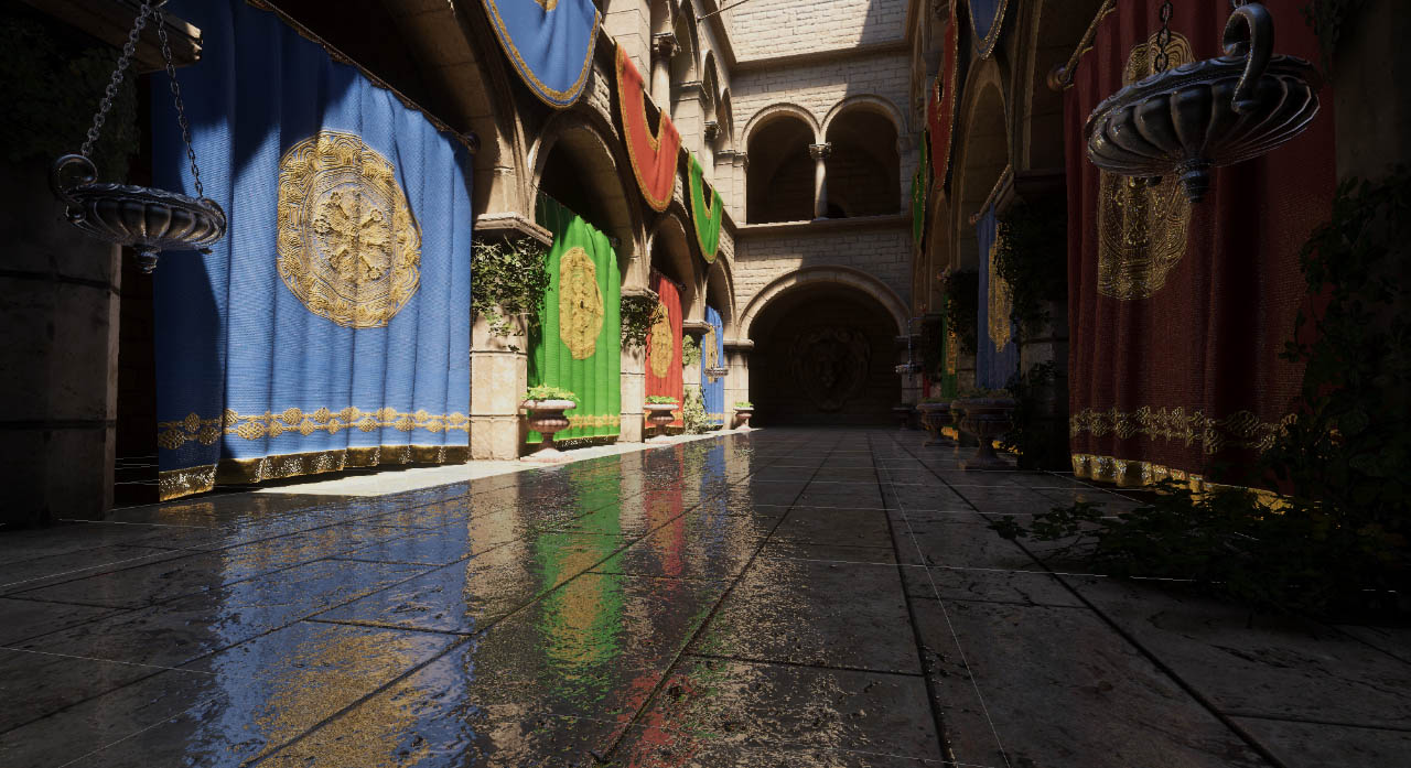
Looks like cel shading, yeah. I think I see an outline shader too
What game is it?
Cel shader = toon shader
out of action
https://www.youtube.com/watch?v=FcppKA4OKXY
how sick is that bro

Wishlist : http://bit.ly/3ZvOwWW Discord : https://discord.gg/KnnfyMaC4y
X : https://twitter.com/DokuGamesLTD Patreon : https://bit.ly/4dJkNkJ
Track composed by Anton Shilo
Yeah, there's no harshness to any of the movement
The gun and the enemies don't look too far of the Genshin Impact cell shading (the methods/shaders used there are quite extensively covered on countless online articles if you want to take a look). Floor/ceiling/walls look more realistic style, maybe combination of some sort of precomputed lighting (like APV) and screen space reflections. Everything is possible but will require some custom shaders etc.
I think this one I have seen before: https://adrianmendez.artstation.com/projects/wJZ4Gg
I'm trying to make a shader where the sprites alpha will flash when the turret is selected. How do I remove this black box around the sprite when the shader is active? (I'm new to shaders so if there is also a better way to accomplish this. I'm all ears)


https://www.youtube.com/watch?v=DlxuvvYZO4Q&t=213s
perhaps this with screen space reflections, as you said, will simulate the light well. plus post processing for colour correction and that

Step into the famous Sponza Atrium to see how to beautifully light an environment from scratch using a mix of baked and real-time techniques. Pierre Yves will showcase the GPU Lightmapper, the new Probe Volume system, ray tracing, and path tracing.
00:06 Introduction
01:18 Speaker
01:40 Volume system
02:47 HDRI sky setup
04:16 Direct lighting &...
only issue is performance as this is hdrp
ill check that article out, ty man
APV work on URP too but unfortunately screen space reflection don't. I think there are some assets that do that though. The game you showed definitely has some advanced reflections though, likely SSR. Could be planar reflections too but rendering everything (or even some of the objects) for the floor and ceiling again doesn't sound very performant either
so URP plus APV and maybe the following SSR asset could simulate graphics like that game?
i’m pretty sure all the materials used in the game were from Quixel as well
https://github.com/JoshuaLim007/Unity-ScreenSpaceReflections-URP
GitHub
SSR solution for Unity URP . Contribute to JoshuaLim007/Unity-ScreenSpaceReflections-URP development by creating an account on GitHub.
thanks for helping me man btw
cause as you said the environment has pretty realistic lighting and materials
whereas the effects and models aren’t necessarily that detailed


Hey hey, I have a simple texture, which is black, and each pixel of that texture has different transparency, based on light level in my lighting system
https://pastebin.com/vH2Z4jEr this is my shader for smoothing light between pixels. (my texture is around 64x64 but has local scale *= 8)
For some reason, when I move and light updates, it starts flickering, it doesn't happen if I don't use the shader
Pastebin
Pastebin.com is the number one paste tool since 2002. Pastebin is a website where you can store text online for a set period of time.
hello everyone so I have made this shader to swap palettes with a revealing effect this is the image having an error so basically ffe773 also gets converted to ffefff instead of just being like in this image here is the shader code https://paste.ofcode.org/fqmgHYk6LYSxLpSvvsyiM apparently it works well with some but in some it doesn't

https://pastebin.com/zv2cCp0w here is the whole light manager, in case it is needed
Pastebin
Pastebin.com is the number one paste tool since 2002. Pastebin is a website where you can store text online for a set period of time.
That might help you https://github.com/Unity-Technologies/com.unity.demoteam.hair

GitHub
An integrated solution for authoring / importing / simulating / rendering strand-based hair in Unity. - Unity-Technologies/com.unity.demoteam.hair
This URP pack?
Supports all current rendering pipelines
Built-in RP
HDRP
URP
Okay...
Glad i helped you.
Noise function question:
Pictured is Photoshop's Filter > Render > Clouds.
When I google what kind of noise this is, the net calls it Perlin Noise.
When I search Perlin in shadergraph, I get Gradient Noise, which doesn't look like what Photoshop produces.
What actually is photoshop's cloud noise and how can I recreate it in nodes?

Other places call it 'Fractal Noise' so I assume there is some steps of plugging the noise into itself? I haven't been able to find an exact formula for how this noise is made though 
Looks like couple noise functions (like perlin noise) with different scales on top of one another (that's where the fractal part comes from). This site plus the code on github might be of interest http://kitfox.com/projects/perlinNoiseMaker/

Oh good find, that does look about exact 👀 Thanks! Ill check that repo out
This seems to be the part of the code that layers the perlin noises on top of one another

These may also help
https://iquilezles.org/articles/fbm/
https://thebookofshaders.com/13/
Do any of the included shaders have an option to use a roughness / smoothness image as opposed to the slider in the universal render pipeline?
Note the Source dropdown under the Smoothness slider. Metallic Alpha for example means the smoothness is read from MetallicMap.a
Where is that map located? can I use the one I generated in blender?
What map?
sorry not map, the roughness image source
You have to put the roughness and metalliness in the same texture. rgb (I assume r alone is sufficient) for metalliness and alpha for smoothness
in that case then, the handle on my dagger model should nott be getting "smooth" but it is. I assume black is 0 smoothness and white is 100% smooth * the value of the slider ?
Note that smoothness and roughness are opposite of each other. If you only have the roughness map, you need to invert that (smoothness = 1.0 - roughness)
That is true, though I wouldn't call them black and white. it's zero opacity and fully opaque
Alpha values of 0 to 1
okay, I have inverteed the roughness imag, now it seems I have to store it in the alpha channel of the metallic image
yup. many image manipulation programs allow to manipulate images per color channel. There are also unity extensions that allows to pack the textures and possibly do the inverting too. Shame unity doesn't have one built in
This one I have used myself earlier https://assetstore.unity.com/packages/tools/utilities/texture-channel-mixer-180690. Remember encountering some bugs with it but it definitely did get the work done
hi! not sure where to ask this but anyone know why it's pink color in the content browser?

Hello, im wondering if someone knows a solution for a problem of mine. I have a compute shader which accumulates triangle normals onto vertices. But i have a race condition which seems to only be fixable by using InterlockedAdd, but this only accepts integers which would need conversions and id rather avoid that. Is there some other way to do this? Here is the code in question:
[numthreads(64,1,1)]
void CumulateNormals (uint3 id : SV_DispatchThreadID)
{
    if(id.x * 3 > triBufferLength)
        return;

    int vertexIndex0 = triangleBuffer[id.x * 3 + 0];
    int vertexIndex1 = triangleBuffer[id.x * 3 + 1];
    int vertexIndex2 = triangleBuffer[id.x * 3 + 2];

    float3 v0 = verticesBuffer[vertexIndex0];
    float3 v1 = verticesBuffer[vertexIndex1];
    float3 v2 = verticesBuffer[vertexIndex2];

    float3 edge1 = v1 - v0;
    float3 edge2 = v2 - v0;

    float3 normal = normalize(cross(edge1, edge2));

    //Does not cumulate correctly because of race condition.
    normalsBuffer[vertexIndex0] = normalsBuffer[vertexIndex0] + normal;
    normalsBuffer[vertexIndex1] = normalsBuffer[vertexIndex1] + normal;
    normalsBuffer[vertexIndex2] = normalsBuffer[vertexIndex2] + normal;
}
thank you!
hello everyone so I have made this shader to swap palettes with a revealing effect this is the image having an error so basically ffe773 also gets converted to ffefff instead of just being like in this image here is the shader code https://paste.ofcode.org/fqmgHYk6LYSxLpSvvsyiM apparently it works well with some but in some it doesn't

Its because the icon for that object is not updated. It should be when you save once.
https://i.imgur.com/Q2FDGgh.png
Let's say I've a render texture where each of these decals represents an entity's proximity. Now, I want to make an interactive vertex shader such as grass trampling, and I'm trying to figure out the best way to handle the trample direction. Maybe something like adding an eye (probably another color value) to these decals then have the vertex operation check a radius away from itself is one idea. Anyone any suggestions? Also looking for resources for this stuff as I seem to not been having that best of luck.
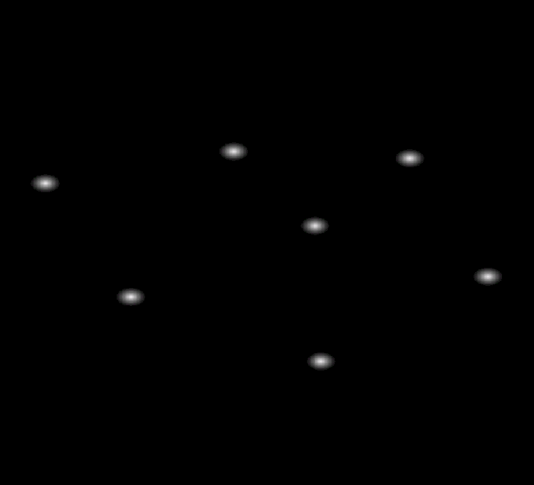
Yeah, maybe that's the idea. Instead of a color, I could also just find some opacity threshold, then grab a direction towards the lesser opacity value.
hello everyone so I have made this shader to swap palettes with a revealing effect this is the image having an error so basically ffe773 also gets converted to ffefff instead of just being like in this image here is the shader code https://paste.ofcode.org/fqmgHYk6LYSxLpSvvsyiM apparently it works well with some but in some it doesn't
Alright question about general PBR stuff. As a sanity check.
If I have some ambient light/color, and a region on a mesh is white and fully illuminated, and I have bloom turned on with a threshold of 1.
I'm assuming it will glow? Right? Like that's the gimmick?
Doesn't seem like I'm getting alpha values when sending these textures into the graph. I'm going assume that's just some funky render texture behaviour as I'm pretty sure I've got a color format that should be providing it, unless it's something to do with these Sample Texture 2D LOD nodes
Considering this image is greyscale does it even matter if it's in the alpha channel? You could just place the info in one of the other channels.
Yeah true. Probably just end up just using the red channel.
Idk where to ask this but i have a transparent shader for a kind of destruction effect and i learnt that unity really doesnt like realtime sorting of anything transparent, which causes conflicts if two destructible objects are infront of eachother or whenever anything transparent like particles goes infron of the destructible objects, this causes incorrect sorting and objects that are behind will appear as if they are infront.
Anyone know any good sources to fix this issue? My game is graphically not expensive so a more expensive aproach is perfectly fine
You could look into Order Independent Transparency methods
Hey guys, I'm making a 2D Pong-like game and I wanted to simulate some waves/ripples when the ball collides with something, as if the game was underwater, and I wanted the ripples to react to each other "naturally"
I have no idea where to start tho, if anyone can guide me toward a tutorial/documentation I would really appreciate it!

Probably need some SDF where each pixel value represents a velocity. Probably similar to how people do wind zones
Otherwise there's always some math solution which I'd probably wouldn't bother with
thank you! it got fixed/updated when i renamed it
Hey, I'm trying to recreate lighting system from Terraria. Thats how it looks right now.
It doesn't look good, I can't tell exactly whats off but I feel like the color is too intense?
Thats my light system: https://pastebin.com/tzHhX1NM
And the shader: https://pastebin.com/H0aiana4
any ideas how to improve it?


Light does not usually use alpha blending, but multiplicative blending
Multiplication
Like this thing *
yes but like, what do I multiplicate, what do I do with transparency etc etc
guys i took a shader material i made with shader graph from an older unity version to the new unity 6 37f version and each material i take always comes like that , does anyone have any idea why ?

I'm not sure why a light texture would have alpha, since there's no transparent lighting
Only varying brightness values and colors
If your light shader is rendered as an overlay, you can blend it multiplicatively with whatever's behind it
I'm not sure why a light texture would have alpha, since there's no transparent lighting
Right now my light is a big black texture thats above everything else, and then if I want to make a tile visbile I just make given pixels more transparent
I expect you probably don't want to do that
Since you get all kinds of weird results that way
Like how the brightest part of the light is darker than the area around it, which in turn has a dull sheen

What would be some ways to bend say grass vertices with the shader graph such that verts lower on the y bend less than those above? I don't really make vertex shaders with the graph, but I'm feeling like I'd probably want some geometry shader for this which I don't think is possible, right?
The only thing I can think of is giving the verts a minimum y to compare to via world position, but that would only work well on flat planes.
But, I could get the object position that the shader it assigned to right? Maybe that's the idea
Painting that info via vertex colors or as other vertex data is a tried and true method
Object position works just as well, but only if they're not batched or instanced in a way that they share the object position
I'm using terrain detailed meshes, I assume that's not instanced, or maybe it is actually
ahhh
What's the painting idea? I'm painting a texture from above using an ortho camera to create some interactive shader for grass trampling already
Kinda where I'm at
The mesh would be modified to include the vertex color
Blender for example has brushes that can be used to paint them directly
The data itself is not that different from UV data, which could be used just as well
The idea is that each vertex has a value that the shader samples and uses to multiply the strength of the vertex displacement with
So like a black to red gradient in vertex color terms, as only one channel is needed for it
Oh interesting, where do I go about sampling that in the graph?
actually that does give me ideas of just painting a texture as well and sampling that
do like a green-red gradient texture
Oh, right you can acess the vertex data directly
duh lol
Yeah painting the vertex sounds like the idea
Sample Texture 2D LOD node works as well if you want to use a texture mask in vertex stage
But since then it's per vertex also the effect is practically the same as with vertex color
One problem with painting vertex though is I do kinda do modify during the fragment stage, but probably ways around it
anyway got some ideas ty
Modify how?
That grass there is all vertex colors, with a texture cutout
UV data works the same for this purpose as vertex color would, and you can have more than one UV channel
Oh right right, sounds like the idea then
anyone here familiar with command buffers? Trying to draw an object by itself normally in a command buffer but the object is not being rendered
[ContextMenu("TestRender")]
private void TestRender()
{
    if (renderTextureConverterV2 == null)
        renderTextureConverterV2 = new RenderTextureConverterV2();

    if (commandBuffer == null)
        commandBuffer = new CommandBuffer();
    else
        commandBuffer.Clear();

    if (renderTexture != null)
        renderTexture.Release();

    renderTexture = new RenderTexture(1024, 1024, 32, RenderTextureFormat.ARGBHalf);
    renderTexture.filterMode = FilterMode.Bilinear;
    renderTexture.wrapMode = TextureWrapMode.Clamp;
    renderTexture.enableRandomWrite = false;
    renderTexture.Create();

    meshFilter = GetComponent<MeshFilter>();
    meshRenderer = GetComponent<MeshRenderer>();

    //Camera camera = SceneView.currentDrawingSceneView.camera;
    Camera camera = SceneView.lastActiveSceneView.camera;

    if (cameraToRender != null)
        camera = cameraToRender;

    Matrix4x4 cameraViewPosition = Matrix4x4.TRS(cameraToRender.transform.position, cameraToRender.transform.rotation, Vector3.one);
    Matrix4x4 cameraProjection = cameraToRender.projectionMatrix;

    commandBuffer.SetViewProjectionMatrices(cameraViewPosition, cameraProjection);
    commandBuffer.SetViewport(new Rect(0, 0, renderTexture.width, renderTexture.height));
    commandBuffer.SetRenderTarget(renderTexture);
    commandBuffer.ClearRenderTarget(true, true, Color.red);

    for (int i = 0; i < meshRenderer.sharedMaterials.Length; i++)
        commandBuffer.DrawMesh(meshFilter.sharedMesh, Matrix4x4.identity, meshRenderer.sharedMaterials[i], i, 0, null);

    //for (int i = 0; i < meshRenderer.sharedMaterials.Length; i++)
        //commandBuffer.DrawRenderer(meshRenderer, meshRenderer.sharedMaterials[i], i, 0);

    Graphics.ExecuteCommandBuffer(commandBuffer);

    renderTextureConverterV2.SaveRenderTexture2DAsTexture2D(renderTexture, "Assets/CommandBufferShadowTest.asset");

    renderTexture.Release();
}
this is my sample code

my actual camera view
but when rendering to a rendertarget via the code above

not showing up
what am I missing?
for the moment I'm trying to do a test to determine if I can render an object normally, with the materials it nomrally has, and see if they also sample a shadowmap, since there is another project I'm doing where this is a requirement
although in this quick test I'm already hitting a wierd hurdle lol
I've rendered objects with command buffers before, and this is the same setup I've also used before... but not getting anything now for some reason?
tldr;
trying to render an object in a command buffer render target, with it's default materials (default unity standard) and its not showing up
and yes, I know for the mesh matrix I'm passing in an indentity matrix, I also have tried (and done in the past) transform.localToWorldMatrix but that doesn't change the oddity thats happening here of the mesh still not appearing
Would it be possible to make these verts slowly lerp back into place after being displaced? Perhaps I can do it with the render texture, but I feel like that may get a little messy.
I guess it's not that bad, but it does feel a little too springy
could do something like a particle system trail perhaps that fades, hmm
Problem with that idea is I would have to give each entity a trail and that kinda defeats the purpose of trying to optimize this lol
does work though
Perhaps you can do it with a computer shader that holds a buffer with a t value for each vertex. The shader will decrement the value and then the grass shader will read it as the t of a lerp to the original vertex position.
It’s how I fade out sphere mask hits on energy shields
I am trying to make a decal that displays a shadergraph I have made on it.
The shadergraph visually looks how I want it, but when I apply it to a material and assign that material to a decal projector it just shows up as a grey block.
Any ideas on where to be begin troubleshooting this?


Why can we still not use gradients as a color input? I know you can lerp two colors to make one as an alternative, but I'm looking for quite a few different colors here.
I think it's because GPUs or shader languages don't really know about gradients so they can't be properties
There's scripts that let you convert a gradient field into a gradient texture which the shader can sample just the same way, which is probably your best alternative
The editor's gradient fields are converted into lerps between an arbitrary number of colors
Which I guess is why they can't be a standard data type
You could definitely implement it on the GPU. But indeed, it’s a complex type
anyone?
So I just fixed a problem, and I don't understand how I fixed it. I have two prongs to this question, starting with this one:
I have a shader that needs to reconstruct world positions (based on depth) in the fragment stage. Therefore, it needs to compute a grab position and use that to sample the depth buffer.
I originally computed that position in the vertex stage and passed it over to the fragment stage.
That worked fine -- until I started testing in VR and discovered that the right eye was getting bogus positions.
I have switched to passing a copy of the clip-space position in a TEXCOORD semantic (because apparently SV_POSITION is...different??), then using that to compute the grab position in the fragment stage.
That works perfectly. Both eyes get exactly the right values.
...but why? 
My second question is hopefully a bit simpler. My fragment stage now looks like this:
i.clipPos /= i.clipPos.w;
float4 grabPos = ComputeGrabScreenPos(i.clipPos);
grabPos /= grabPos.w;
float depth = SAMPLE_DEPTH_TEXTURE(_CameraDepthTexture, grabPos.xy);
Why am I dividing by W here?
If I don't do that, it violently explodes
This is in VRChat, so I'm doing single-pass instanced rendering
Interestingly, I realized that I completely forgot to include any of this stuff...but that doesn't seem to matter https://docs.unity3d.com/Manual/SinglePassInstancing.html
I don't know much about ComputeGrabScreenPos in particular but similar to ComputeScreenPos, the divide by W would be the "perspective divide"
yeah, and we're using homogeneous coordinates
so, IIRC, [1,1,1,1] and [2,2,2,2] represesnt the same 3D point
i need help this is my first week using a game engine. i want to try game development but im getting pink textures. i bought this environment from the unity store. can anyone help me fix this in beginner terms. thanks

These materials probably use custom shaders