#archived-shaders
1 messages · Page 95 of 1
i wonder if the albedo color's alpha gets clamped to 0..1
given that it's not an HDR color, typically
Are you writing a surface shader here?
yep that was it
How to make a cubemap reflection
Baking a reflection probe?
Shader
I tried using cubemap skybox but surface just vanished
Btw what is reflection probe is
Google that :P
I think it bakes to a cubemap as well
I think there is a Sample Cubemap node iirc..not fully sure on thay
Likely also findable on google
I have cubemap
I want to make a mirror
Hmmmm maybe calculate the direction the mirror goes in than?
Like calculate the bounce angle
What include do i need for Linear01Depth in URP when using HLSL? i am not really familiar with shaders. I am trying to convert the depth of a depth texture to a linear value and output it on screen so i can clearly see objects further away change color.
This is my shader so far. With the Linear01Depth i get an error about no matching 1 parameter function found i think. so i assume it doesn't find the Linear01Depth function
Shader "Hidden/Test"
{
    SubShader
    {
        Tags
        {
            "RenderPipeline" = "UniversalPipeline"
        }

        Pass
        {
            Name "Test"

            ZTest Always
            ZWrite Off
            Cull Off
            Blend Off

            HLSLPROGRAM

            #include "Packages/com.unity.render-pipelines.universal/ShaderLibrary/Core.hlsl"
            #include "Packages/com.unity.render-pipelines.core/Runtime/Utilities/Blit.hlsl"
            #include "Packages/com.unity.render-pipelines.universal/ShaderLibrary/DeclareDepthTexture.hlsl"

            #pragma vertex Vert
            #pragma fragment Frag

            float4 Frag(Varyings input) : SV_Target
            {
                // better performance?
                UNITY_SETUP_STEREO_EYE_INDEX_POST_VERTEX(i);

                float depth = SAMPLE_TEXTURE2D(_CameraDepthTexture, sampler_CameraDepthTexture, input.texcoord);

                float linearDepth = Linear01Depth(depth);

                return float4(linearDepth, 0.0, 1.0, 1.0);
            }

            ENDHLSL
        }
    }
}
The Linear01Depth function in URP has 2 params for some reason, so iirc needs to be Linear01Depth(depth, _ZBufferParams)
ah thanks, that worked!
I'm trying to learn shaders in unity and am trying to apply a rendertexture to a WaterMesh that I have that has it's own material. The game is a 2D platformer and from what I've heard you need to create a second camera, set the output texture to your new rendertexture with the layer pointing to the water and exclude it from main camera. But I'm stuck at the part where I can see the water rendered with both cameras since there isn't many resource about it online.
Any ideas?
You'll need to explain better what you want. Is it just a normal mirror? If you can't explain, share a video/screenshot showing what kind of effect you want to implement.
Not entirely sure what you're trying to do, but you can exclude a layer from the camera culling mask(or whatever it's called) to make the camera ignore objects on that layer.
I have a water mesh that am trying to make look pixalated. So I have assigned it to a "Water" layer. It's the only layer on culling masks for the "Water" camera and it's excluded from the normal camera. But now that the camera is outputting it to a texture renderer. Is there a smart way to display it on the same location and size where the "Water" mesh is supposed to be
Well, render it with a sprite renderer or a mesh renderer with quad mesh. And if you need to automate it, set it's position and size/scale with code.
Does anyone know how to integrate a splatmap into a shader graph? The way I have it is I isolate each color using smoothstep and/or subtract, and then multiply that with the texture, and add all textures back together for the final product, but the result is terrible and extremely pixelated for the base color, and utterly broken for the normals. I know it's more straightforward with terrain tools, but I'm using my own procedural terrain implementation.
What I do is just sample each layer's texture in order and Lerp the color from the previous one, using the current splatmap channel's value as T
Normals can be blended with Normal Blend node
You need to use Normal Strength on its inputs to have correct weights
does the chain of successive nodes reduce the quality?
Nope, not sure what that is about, maybe show the shader that you tried?
Looking at my shader now, I made a subshader like this for the blending:

And in the main shader I just chain those:

This could be an issue of the quality/depth of the splatmap texture. Hard to say without more info tho.
Oh and the SampleTerrain subshader just samples the three textures

This setup supports 5 texture layers, first one is the base layer (at zero splatmap 0, 0, 0, 0), and the next 4 are blended according to R, G, B, A
Can be extended to use more too. I just didn't need that yet
the textures are sort of put together from the internet in haste and are temporary. They look like shit but the problem is in the lost detail ruining the seams. Here I isolate each color in the splat map with smoothstep/subtract/multiply and then add them together again. I disabled the normals here.


the splat map is 2K
Can you show the full splatmap you are using
Which I suppose is this

it's not your usual splat map. It's a satellite map projection for a grand strategy game prototype. Not the final thing, but I'm using it to build the 3D map

blue is sea, clear is desert, cyan is lakes and rivers, green is grassland, red is swamp, yellow is mountains, and white is icy mountain peaks.
It seems to have very sharp edges, so I'm not surprised that smoothstep does not give a smooth result
Oh I just opened it in browser, it is indeed pixel sharp
And huge
I see. would "step" be any better? I tried it with a texture mask and it was much harsher
It's a bit hard for me to follow the logic in your shader. But I suggest trying the consecutive lerping method that I also used
yeah 2k and I made it intentionally sharp like that to have defined province borders to work with in the script
i guess I should separate both workflows
oh yeah you're right. this is 4K, but the one in the game files is 2K
but ithey're identical
Looking at the 4k texture, looks like each pixel is actually 5 pixels wide

(just put it into paint and drew those lines for measure)
well I did upscale it
What if you just toss it into something like Gimp or Photoshop and blur it?
If you want some smooth transitions
Because, sharp large pixels don't get you any smoothness
I'm gonna try that, but do you think the logic in the shader is sound enough?
I can't really comment on the shader logic
Takes too much brain power right now to understand it
Smoothstep is probably a decent way to do this, but it doesn't make sense when you don't have any smooth transitions in the splatmap
I would try something like this
Image 1 = original
Image 2 = +median blur (4 pixels)
Image 3 = +gaussian blur (3 pixels)


Gaussian blur did the job. Thanks

But I think there are still problems with the logic, since it gives the borders this purple color, and some of the mountain peaks are detected as sea around the edges
You can show your shader so me or someone else can take a look. The screenshot of the shader graph you showed is too low res to understand
There is a zoomed-in screenshot that shows part of it in the same message
I know but still. Would be easier to see it in context.
ok
I couldn't find a way to get it all in a detailed screenshot. so here is a link with the source file and the base color textures and the splatmap
https://www.mediafire.com/file/anfj82ffopari5a/terrain_shadergraph.zip/file
If just the graph is enough, here it is.
I wanna blur harsh lines from the vornoi cells but I don't know the node for it in shader graph
I see that Unity Toon Shader URP is not compatible with Unity 6, can you please recommend me the alternative that is compatible with Unity 6?
I would like to get the worldspace position of the pixel, is this correct or does the depth need to be linearized? i am not sure how i can best test if it's correct for shaders.
float depth = SAMPLE_TEXTURE2D(_CameraDepthTexture, sampler_CameraDepthTexture, input.texcoord);
float3 worldSpacePosition = ComputeWorldSpacePosition(input.texcoord, depth, UNITY_MATRIX_I_VP);
I think this is probably right, i just find it hard to verify if it's correct.
Im suck at hlsl
Mirror
Just a mirror
I know about camera method but i need cubemap for better performance
You Can probably just use a reflection proble and a completely reflective surface.
Ok i will google that
But i also need help with mirror-y surfaces
Ill send screenshot later
You could also sample the texture at different mip levels to get some blurring for free, btw

This effect
And this mirror

They are made from cubemaps
I used assetexplorer
A cubemap is just a texture type. Reflection probes bake cubemap textures as well.
This doesn't tell anything about how they are rendered.
Luckily, unity standard shaders support reflection probes out of the box. Just use a reflective material.
Which shader i need to use on material?
Note: im using unity 2022.3.45.1f
The standard shader for your render pipeline
and put this crap into aldebo?
+how to do hdri
you helped me alot, and i will be so happy if you tell me this lil thing
No... Make it a reflective material and bake a reflection probe near the object.
wdym by hdri?
"what do you mean"(wdym)

As I said many times now. You can use a reflection probe with a reflective material.
thank you
can you please make a screenshot of mat properties
like where to put cubemap
i have cubemap
You don't put it anywhere
The santadard shader would use the cubemap generated by a reflection probe automatically
If you want to use a custom cubemap texture, you'll need to look up a shader that does that or create your own. Should be pretty simple with a shader graph.
so i should create a file?
There are probably some built-in (legacy or mobile) shaders that can use a cubemap texture directly, like legacy/reflective/diffuse or something
No. You should learn about reflection probes and how to use them.
God at some point you need to go learn about this properly yourself...
i found
Legacy > reflective > Bumped (any)
lerping instead of adding fixed it!

Hi, I need some help, been looking around the internet a lot already (and chatgpt).
I'm using a Scriptable Renderer Feature with the Render Graph API. In it I am currently only rendering vertex colors for my edge detection to a texture and use it later in a post processing shader made in Shader Graph. I'm using drawSettings.overrideMaterial in the render feature pass for this and it works well.
Now, I also need to include a single integer/float that is different per game object, it's essentially an ID and I need to render it into a texture along the vertex colors (ex. R channel is vertexColor.x, G channel is vertexColor.y and B channel is the new ID). The problem is I've no idea how to properly pass this ID from the game object (or it's base material) to the pass inside the renderer feature.
- I tried MaterialPropertyBlock, but it doesn't work with the batcher.
- I tried to use drawSettings.overrideShader to keep the base material properties, but it was glitchy and didn't work with the batcher.
- I didn't try just constantly having 2 copies of each game object with different materials on different layers and rendering them separately, but this seems to be a giant hack (but still may be more performant than the property block).
Any help? 🙂
What’s the ID for? What value will you give it? You can do a hash based on world position maybe?
Or encode ID in vertex color G channel, depends on what you use the other vertex color channels for.
Or MPB + GPU instancing if you have many of the same meshes.
ID is actually a "group id" (so edges will apprear between two groups of game objects in my edge shader) and it may change per object at runtime (so writing it into the vertex color is no). Instancing may help a bit. I guuess I really need to some wonky stuff.
Hey there! HDRP's fullscreen sample shaders cause this error to appear:
A BatchDrawCommand is using the pass "DrawProcedural" from the shader "HDRPSamples/EdgeDetection" which does not define a DOTS_INSTANCING_ON variant.
This is not supported when rendering with a BatchRendererGroup (or Entities Graphics). MaterialID: 761 ("Belt"), MeshID: 2855 ("Hand_watch"), BatchID: 3.
As far as I can tell, Unity expects these shaders to be DOTS-compatible, which they're not, even though I'm not using DOTS? Is this a bug, or does anyone know a solution?
How do you know Unity expects them to be DOTS compatible? If they are just a HDRP sample?
Because of what the error message says? I also tried googling it and it seems to be what others suspect too
Ah you’re not using DOTS, missed that
Do the shaders also break?
Yeah, when i try to use the materials associated with them in the scene, the materials break and this error appears for each mesh renderer that tries to use the material
It feels like a very random bug so I'd try restarting the editor or even importing the sample into a new HDRP project before digging too much for the cause
I'll try that, thanks
Seems something has change in Unity 6 which meant my Custom Pass setup somehow caused the error. Thanks for the help anyway!
Is there a way to set up a camera that only captures shadows? I've tried a shitload of different setups, but no matter what I can't figure out a way to capture the shadows of a renderer to a render texture. Setting the renderer shadows only always culls it from my camera. I need a way to create a mask texture from the occluders in my scene. Making these occluders visible but excluding them from the culling masks of my main cameras isnt an option because if i did, they wouldn't be able to cast actual shadows in those cameras
im trying to set up a raymarched shadow shader and to do that i need an accurate mask of the occluders in the scene drawn to a texture so that i can test intersections with that mask
Sorry for necro'ing this... what kind of node is the "SpecularAO" node?
I guess you could make an RT camera with an override shader renderer feature (or render pipeline equivalent) using a shader that has no other light or color calculations besides casting and receiving shadow
I don't know how that'd help with raymarching though, or if that would be the "mask of occluders" you seek
Renderdoc supports vulkan, so it should be.
Are there any techniques to get pseudo-normal maps?
Either generate them from the source texture or something else?
Just something to get a sense of curvature along an image.
The results can be a bit jaggy though
just get the difference between current height and neighboring height
you'll need atleast 3 samples, current, nextHorizontally and nextVertically.
It should be fast (iirc, opengl es2 can sample up to 8 textures simultanously), I managed to run it smoothly even on my old samsung galaxy a02 phone
I believe shader graph has the DDX and DDY nodes.
yes, but
The results can be a bit jaggy though
Are there any tools that help with the generation of normal maps? I'll be honest, how do these things even get made typically?
Higher fidelity model or something and we slap it onto a lower poly one?
Typically high poly to low poly baking
Generating them from textures is for when you don't need to capture exact normal detail or if the surface is relatively flat and the pattern is generic
Gimp has a very simple height to normal filter, which I like to use with its mean curvature blur if I want something quickly that looks pleasant but accuracy isn't that important
XNormal is a very powerful tool for pretty much all types of normal map generation
Blender can bake normals from meshes as well, and you can implement your own setup for baking them from heightmaps as well which gives you more precise control and lets you easily use Blender's procedural geometry for making normal details
But I guess it depends on what you mean by "pseudo-normal maps" and "sense of curvature along an image"
Another decent, simple normal map generator: https://cpetry.github.io/NormalMap-Online/
(I think you have to invert R to make it OpenGL format)
That one looks to have the same algorithm as Gimp, but has more generators in it
At least the grainy artifacts are the same, which the mean curvature blur is useful for removing while preserving the shape
So I was looking at the Bazaar. It's one of those "deckbuilding" games with lots of cards. In the game, you can enchant the cards with various effects, and every card in the game (literally hundreds) can be enchanted. There is one enchantment that results in this blue scrolling texture that appears to wrap around the item in the card.
This effect can appear on hundreds of items and behaves the same way. I was thinking to myself there's no way they created normal maps for every item?
Are those 3D rendered or hand painted images originally? Hard to tell with that resolution
If 3D rendered, the normal map can just be rendered in another pass when rendering/baking the image
Pretty sure hand painted flat textures.
The second item from the left is "enchanted" with a shield effect.
That one I can see as just being powered by a mask.
Could be 3D rendered and hand painted on top, using the normal map from the 3D layer
Or even AI generated 🤷♂️ (The normals I mean)
Even this shield effect is kind of impressive.

It has an outline to it.
Idk I just can't imagine multiple masks being made for each of the hundreds of items in the game?
It can be automated if they used a 3D render as the base
Rendering out normal maps, depth textures and whatnot
Sorry do you mind elaborating? What do yo mean by a 3D render as a base?
Not saying that's for sure what they did, it's just what makes the most sense to me
Like they make the icons in 3D and an artist paints on top of it
The 3D can be used to render out the needed maps
Oh like the creature in the frame is actually 3D and they just draw over it >_>
Yeah
Idk we see these frames rotate a full 180 in game and I don't really see anything 🤔
Though I guess it could be slight?
They all look pretty far from 3D so it's more likely the normals are generated
Though, the sheen is not consistent with what you'd get just by generating from grayscale
So it could be offset by a diagonal gradient or similar in the shader
Or the normals could be AI generated
the shield effect could be just some masking trickery. maybe using sine wave for comparison
Do you happen to know of any good AI generation tools for normals? That seems like a good use of the tech.
Ya it does seem like a mask. Maybe They have some SDF in the shape of the creature and define some ranges for the outline/diamond shapes?
The shield effect looks rather simple depth-wise but this effect looks pretty 3D to me^
Definitely.
I don't, and you don't need a "good" result if you want a similar effect, since even an inconsistent normal map would make for a visually interesting sheen
Hi! I am making a dissolve shader graph, and for some reason the mesh's shadows are rendered on top. Is there a way to fix this?


Does it need to be transparent or could you go with Opaque + Alpha clipping?
It's either 100% transparent or not, so I guess alpha clipping would work?
I don't know though how to enable debug symbols on Linux and if it's even possible, I see only compiled command buffers and SPIRV decompiled mess :(
It fixed the issue. Now it looks bad in a different way though

It doesn't look invisible
Well, not when it's in front of the water anyway

You made it opaque, right?

Yeah


I see

The threshold value was too low
Thank you so much 🙏 ♥️
Hey just to make sure I'm not crazy, when setting up a normal map in shader graph, you need to set the texture type to Normal Map (in import settings) and set the sample type to Normal in the Sample Texture 2D node, right?
Sounds correct to me
Hmm. Double checking these settings, it just seems related to cleanup/storage.
Making sure values are normalized and stored in optimal channels.
I can just use the map raw if I wanted.
I have a shader I want to use when the player "spawns" objects. There is a value in the shader that I want to continually change for 1 second in my script when an object is spawned. This makes the object look like it is appearing out of thin air. What if the player spawns another object during that 1 second? Will the new object and the old one share the same material? Is there a way to create a new instance of the material, so that I can update their values individually?
construct a new material and give the current one as an arg to copy:
https://docs.unity3d.com/6000.0/Documentation/ScriptReference/Material-ctor.html

mesh renderers should instance anyway automatically or when you access via .material.
what is shader graphs
You can't, it needs to be marked as normal map if you want it to work correctly
The normal vector range is different in a normal map thab other maps (-1 to 1 instead of 0 to 1)
Even if you do normal reconstruct after the texture, it won't look as good because marking it as normal changes the compression setting to one that is special for normal maps
The only thing you can do i use the alpha channel of the normal map for something else because alpha channels are uncompressed
Thank you :D
Hey, I'm trying to make the edges for the water mesh match the aesthetics of the game by making it look pixealated. I'm lost on how I should go on about doing it since I'm new to shaders and I can't seem to find any resources online doing it either. Here is my shader graph is anyone is interested


Hellou, I made this method, which is nice, but interlock add slows it down
[numthreads(GROUP_SIZE,1,1)]
void Count(uint3 id : SV_DispatchThreadID)
{
    if(id.x >= _MaxInstances)
        return;


    uint index = _ReducedIndices[id.x];
    uint LodValue;
    uint Transition;
    uint ShadowTransition;

    uint VisibleNormal;
    uint VisibleShadow;
    UnMask(_TargetLODs[index], LodValue, Transition, VisibleNormal, ShadowTransition, VisibleShadow);

    if(VisibleNormal > 0){
        if(Transition > 0)
            InterlockedAdd(_Counters[LodValue].countTrans, 1);
        else
            InterlockedAdd(_Counters[LodValue].countBase, 1);
    }
}
I was thinking to modify it so that in an for loop insead each thread i handle multiple of those cases, and only call one interlock add at the end, essentially making part of it sequential. THe method is fast enough that it could work. However, is there any better way to reduce the amount of IntterlockedAdds? like some kind of global variable in the thread group or something like that
An easy way is to reduce precision on uvs to introduce pixelation. Should also be usable in other parts of your shader for frag or vert stuff.
E.g. round(UV * 256)/256
Example of a pixelation post shader I did a while ago (for sbox but same concepts apply)
https://gist.github.com/rob5300/0d93056e8a2cd710eea801e8ad6984cf

Gist
Retro Pixelation + Low Bit Colour + Dither Post Processing Effect for S&Box - pixelate_colour_dither.vfx
You mean I apply a Multiply (16 bit) * UV -> Floor -> Divide (16 bit)?
yea thats another way to write it i just gave an example of reducing a 0-1 value to 265 possible values only.
oh i see! i did try doing that on the line calculation already but it still didn't work. should it be applied to every single UV maybe?
Here is the example i tried:

yea if you want it to affect something then ofc it needs to be applied?
you can also do a custom function to make it a bit cleaner or group it
ye i meant i applied it but visually it didn't really change, it looks the same
what thing specifically do you want to make "pixelated"? Texture sample?
I want to go from img2 to img 1:


can you be specific
first image has edges when the line is "curving" while image 2 just curves so it doesn't have that pixealated look
it gives it more of that retro 16 bit look while the other looks vectorized
reduce the depth to make the "steps" larger
you mean here?

dunno what you have before but you want the position to be reduced in depth
Anyone have a good SDF generator?
WDYM by "generator" ?
And what do you consider "good"? Does it need to run in real time or just in editor? Does it need to be exact or is performance more important?
alright ill try it out later, thanks!
Sorry. I just mean a tool to take some greyscale mask as an input and pumps out an SDF.
Like contour represents 0.5 etc etc
So i got this now
[numthreads(GROUP_SIZE,1,1)]
void Count(uint3 id : SV_DispatchThreadID)
{
    if(id.x >= _MaxInstances)
        return;

    uint index = _ReducedIndices[id.x];
    uint LodValue, VisibleNormal, VisibleShadow;
    UnMaskBasic(_TargetLODs[index], LodValue, VisibleNormal, VisibleShadow);

    _sharedCounters[LodValue] = 0;
    GroupMemoryBarrierWithGroupSync();
    if(VisibleNormal > 0){
        InterlockedAdd(_sharedCounters[LodValue], 1);
    }
    GroupMemoryBarrierWithGroupSync();
    InterlockedAdd(_Counters[LodValue].countBase,_sharedCounters[LodValue]);
}
the problem is that it doesn't compile, so im not sure what would be the appropiate way to write back to the global buffer?
You can do this with photoshop or similar, using the gradient outline or the inner/outer lights effects.
Or tools like Substance Designer, Mixture (in Unity) have nodes for computing distances from shapes.
@dapper heath Don't cross-post.
my bad, I wasn't asking the same question, I was asking a new question using the original as reference
I originally asked about the source of my camera jitter, then someone answered me and I realized it was a camera matrix issue, so I asked here about camera matrices and how to round them with a rotated camera axis
You still have unaddressed questions in the second channel you've reposted.
that is true, I read up and realized camera matrices are probably not a shader thing
apologies
do you happen to know anything about matrices
I mean the people are still trying to help you there
I got the impression they were more interested in telling me that I crossposted than the problem at hand
yeah that's what I'm referring to
I read through his chat history and figured he probably wouldn't be able to help with the matrix thing
but I didn't want to be rude and say that
Hello, need a tip. I'm in the default renderer 2D (so not URP), trying to write in HLSL (which I don't know that well).
I currently have a lot of objects consisting of 2 sprite renderers, so I can combine 2 sprites with different colors for tons of variations with little graphics data. Now to get better performance I thought about combining both sprites into one spriterenderer with some cool shader which takes in a texture, 2 colors and 2 vector4 (or similiar) to draw the 2 sprites combined. I can manage the sprite combination and coloring, but the UV mapping? I can hardly make sense of it with SpriteRendrer...
Any tips on how to calculate UV stuff from a Sprite reference in C# and then render that sprite in a shader using a texture and a vector4? Thanks 🙏
Sprite renderer creates a mesh with the uvs needed to show the sprite. You have to counter this in shader to "use" another sprite.
I wouldn't bother you are doing all this to not draw another sprite... If you make them all full rect they are only 2 tris...
well in my testing eliminating the child gameobject holding the sprite gave a decent performance boost (20 -> 40 fps) (I'm working on other optimizations too, 40 is still bad, but this seems like it'd help a ton)
and to be clear we're talking 10k objects, having 10k less gameobjects in the scene helps a TON
(of course the best solution is to use GPU instancing, but I am too noob and I think I can get away with this if I optimize other areas too)
if you can use more spritesheets then more will be batched, or is that already something you are doing?
I have a single texture with all sprites.
If you want to go this route you need to calculate the uv min/max for the other sprite and set it on the material for use.
If the sprite renderer is already showing another sprite from a sheet, you need to provide this sprites uv too so you can correctly calculate the final UV
very interesting. How exactly does it work? I found this part very confusing... How does sprite renderer even know what to draw? I only set the sprite sheet texture through property block, yet it renders only one sprite, not the entire sprite sheet
or do invidividual sprites somehow generate their own texture? That sounds very strange though
A sprite is just a rect and a texture2d reference. the rect is the size and pos of the sprite in the sheet.
The sprite renderer therefore just generates a mesh with the required UVs on the verts and thus it draws the sprite
I set the parameters through script though, I only set _MainTex (to sprite.texture), why does it render one sprite instead of the entire spritesheet?
the sprite renderer component generated the mesh so unless you change it there it probably wont get updated correctly
how annoying. How do I do that?
SpriteRenderer.sprite ?
im not 100% sure if you can make it rebuild the mesh or if the mesh is actually held in a hidden component or not
Hmm, but hypothetically if I set it to the full texture before hand, then I can do easy UV calculations, no?
Im gonna test it out
yea i guess so if you make a new sprite instance with the "sprite" being the whole tex.
Ofc this presumes then your sprites are all square or the same aspect ratio
oh, that is quite annoying, the same aspect ratio isn't neccesserily always true. Although if I make a bounding box big enough to hold any single sprite, then it should be fine, right?
Trying to recreate mapping from blender in unity, so far so good, it's based on screen, but it changes it's size when I move closer/further (blender one is too being shown on screen, but the size of the pattern stays constant, I tried multiplying by distance from camera, but it's not really it
Any suggestions? Using Built-In, ver. 2022.3.9f


hey, I'm following a URP shader tutorial and trying to adapt it to BiRP
TransformObjectToHClip() is a URP function, and I don't know how it works, how do I replicate it in BiRP?
That ought to be the UnityObjectToClipPos function
thanks
Hey, I'm still trying to solve my pixealated water shader issue and have now made the waves move in a pixealated way. My next step is to make the lines the 16 bit edges retro styled. I have tried pixealting the UV by multiplying it then rounding it then dividing it but the line height size seems to be the only thing affected and nothing else. This is my current image together with its shader graph and the one next to it is my goal image:


(Line Length: 0.92, Bits: 16)
Any help is appreciated!
I think I figured out! It seems like since I am using a mesh that is procedurally generating the mesh when I resize the mesh the pixels also get resized along with it. That way it doesn't become "pixealated" anymore.
Does anyone know a way around that? Maybe something with vertex position?
The mesh will need to be created in a way to do this I think judging on how its working rn.
If the water height was all in the shader then it would work with the prev method
Maybe transforming object to world would remap the pixels?
I would like it to be dynamic since I will be reusing that material
I think as long as you use the mesh to define the top its going be hard to do this effect nicely
If you can split the water into some horizontal sections then you can maybe do something? im not sure at this point
helo im new to unity in the shading department and i was trying to learn shadergraph to make a simple hologram shader but i dont quite know what im doing, i was trying to follow a person on YouTube (https://www.youtube.com/watch?v=wVmhqzzkFYE) explaining how one can create one but i cant seem to figure out some of the stuff he shows as he was using a diferent version of shadergraph and a different version of unity it seems because some of the stuff he shows does not appear there for me and i was wondering if anyone was willing to take a few minutes and explain to me a few things. sorry to bother anyone

In the last video, we created holograms in Shader Graph. This time, we're adding distortion and noise effects to add a bit of imperfection - it's like making the effect look worse, in a good way!
✨ Read on my website: https://danielilett.com/2020-07-21-tut5-10-urp-hologram-2/
💻 Get the source on GitHub: https://github.com/daniel-i...
can you list some things you couldn't find? this does look to be semi old but id expect the nodes and logic to work the same now
well my first problem came to the property he called _RECEIVE_SHADOWS_OFF and how when i go look at the debug menu to add it, it shows a different thing than what he showed and when i try to add valid keywords it always adds then to the invalid keywords

I also dont quite understabd what funccion it does as i cant see any shadows in said materials
it was probably a keyword that would cause the shader to compile and leave out stuff that shows shadows. If you don't have shadows showing on the material then dont worry about it.
to be clear, its to disable shadows rendering ON this shader itself
shadow casting is different
This is how it looks like. I am not sure how to solve this.
and this is shader I am using:

 mesh.SetVertices(vertices);
 mesh.SetColors(meshColors);
 mesh.SetUVs(0, uvs);
 mesh.SetUVs(1, meshScales); // Scale
 mesh.SetUVs(2, meshOpacities); // Opacity
 mesh.SetUVs(3, meshRotations); // Quaternion rotations
 mesh.SetIndices(indices, MeshTopology.Triangles, 0);
I have all this data that I pass in the code, however in reality don't use most of it yet at all. As I apply most of data on vertices data.
new to shader graph, trying to make a full-screen blur effect,
Can someone explain why I can't connect the URP Sample now to the shader I found?
It won't let me connect the output to the first input of the shader

cant really see the graph clearly but from the video it looks like normals are inverted and with you setting custom mesh data its probably not recalculated.
try recalculating those and tangents and see if it helps. Best idea i have rn anyways
well you cant give a vec4 to a texture input so its not gonna work
Seems like the first node outputs a color (float4) and the second one expects a texture
the node must sample the texture inside it, if its yours modify it to accept any color vec3/4
here is the code
{
    float4 col = float4(0.0, 0.0, 0.0, 0.0);
    float kernelSum = 0.0;

    int upper = ((Blur - 1) / 2);
    int lower = -upper;

    for (int x = lower; x <= upper; ++x)
    {
        for (int y = lower; y <= upper; ++y)
        {
            kernelSum ++;

            float2 offset = float2(TexelWidth* x, TexelHeight * y);
            col += Texture.Sample(Sampler, UV + offset);
        }
    }

    col /= kernelSum;
    Out_RGB = float3(col.r, col.g, col.b);
    Out_Alpha = col.a;
}```

COuld you point me how to update this?Ah i just realised this wont work unless you can access the raw texture/buffer as that node is only to sample it.
otherwise you will need to re create this in nodes to work with it
hmm. I can't find much about this, do you know a good tutorial for creating full-screen effect? I need to create a guassian blur that affects just the top part of the screen. Unity's documenation about the "URP Sample Buffer" is extreamly limited
I will try to do so, but doesn't normal shouldn't be effecting it, if it is being rendered both sides? As if I change it to opaque it renders it correctly. I will try recalculating anyways, but just to make sure.
While normalize does not effect it at all. If I flip vertices array, it displays another side correctly. So it is about order of vertices indeed. So I need to find a way how to either manually change order in run time depending on distance to camera, or somehow use depth buffer and let unity handle it. But neither I know how to do exactly
small question regarding shader graph vector one refers to a normal float?
On old versions, yes. On newer ones it is just float
ok thank you
also im not sure if i followed said video right as the mesh of the material appears on a difernt space

never mind i did something wrong i fixed it
is there a way to use this shader that is showed in the video but to make it so if the mesh has overlaping stuff it wont do this?

You'll need to do some kind of depth or stencil test to avoid rendering overlapping geometry.
and where would i add the depth test
In your pixel shader. Though you'll probably need an additional pass to render the depth to a texture. You'll probably need a custom depth texture if it's a transparent material.
Might be easier and more performance friendly with a stencil buffer🤔
im sorry i dont quite know what a stencil buffer is
You'll need to learn it then.
ok something to add to the list, ill study it tomorrow thanks tho guys this helped me a bunch
2D URP sprite shadergraphs seem always multiply SpriteRenderer color with the color I passed to fragment base color in my shader graph. I there anyway to ignore this behaviour?
please check this simplified example. I expect the output is white(HitColor) but is green(SpriteRenderer color)

the sprite renderer.color property sets vertex colours. I presume the sprite unlit base does this always for you hence the problem
Unity6+ versions should have an option to disable this in the graph settings. But afaik can't be done for older versions
Does anyone know how to pixelete this shader?

Like so ?

thx
Texture Atlases and UV makes me very annoyed. (just venting.)
I have been working with unity for 3 years, but thw thing is, i have 0 knowlage of shaders.
Is there any resource where i can learn how shaders work? Like, any recomendations?
Unity manual has some sections on the shaders. Then there's the shader graph documentation.
Aside from that just start f on learning how computer graphics and 3d rendering works in general.
It's just to wide of a topic to even explain where and what to learn.
Studying https://www.shadertoy.com/ was a fantastic resource when I knew nothing about shaders, especially very simple ones that are easier to approach
glsl is virtually identical to hlsl too which is quite helpful
if I update mesh.uv4 in a C# script, and I have a HLSL shader that has texcoord3 in the appdata struct (so I read it from the vertex shader to the fragment shader), is the fragment shader going to get the updated value?
I dont see why it would not. Are you asking because it doesnt work?
Show the C# part where you change the uvs
1 sec
in start():
    void Start()
    {

        mesh = GetComponent<MeshFilter>().mesh;

        var uv4 = new List<Vector2>();


        for (int i = 0; i < mesh.vertexCount; i++)
        {
            uv4.Add(Vector2.one*2);
        }

        mesh.uv4 = uv4.ToArray();
in frag:
       fixed4 frag(v2f i) : COLOR
                {
                    if (i.uv4.x >= 1.9 && i.uv4.x <= 2.1) discard;
in vert:
o.uv4 = v.texcoord3.xy;
in hlsl:
              struct appdata_t
                {
                    float4 vertex : POSITION;
                    fixed4 color : COLOR;
                    float3 normal : NORMAL;
                    #if SHADER_TARGET >= 40
                    centroid float2 texcoord : TEXCOORD0;
                    #else
        float2 texcoord : TEXCOORD0;
                    #endif
                    float3 worldPos : TEXCOORD1;
                    uint id : SV_VertexID;
                    float4 texcoord3 : TEXCOORD3; // <-- this is uv4 right

                    UNITY_VERTEX_INPUT_INSTANCE_ID
                };

                struct v2f
                {
                    float4 pos : POSITION;
                    float4 color : COLOR;
                    #if SHADER_TARGET >= 40
                    centroid float2 texcoord : TEXCOORD0;
                    #else
        float2 texcoord : TEXCOORD0;
                    #endif
                    float3 worldPos : TEXCOORD1;
                    uint id : TEXCOORD2;
                    float2 uv4 : TEXCOORD3;

                    UNITY_VERTEX_OUTPUT_STEREO
                };
Thanks G. Though it took me several days of trial and error the path you sent me down was bountiful

Cool!
How do I fix this issue? I'm trying to get the blue mesh to wrap around the car, but I get these holes in the mesh.


It's because the model has some hard edges.
The vertices on hard edges aren't shared between faces and they have different normals, so they extrude in different directions
It's a common issue with this technique
How do I modify the model to fix this? Preferably in script because I don't want to have to manually make a second version of each model
Maybe there's a library or built in function for welding vertices of a mesh together. The shading would look different then, though
Maybe a post-process/fullscreen effect is more suitable here
I know for a fact that builtin functions won't save me. RecalculateVertices isn't working
You mean RecalculateNormals? It isn't supposed to work on hard edges
Unity creates duplicate vertices for hard/sharp edges so they have different normals per each face
If having two versions of the model, one with flat shading and one with smooth shading is not an option, I would definitely look for post procsessing outline effects like Osmal suggested. The extruded mesh outline method is limited to smooth shaded meshes (no split edges) and even when you get it working, it cannot guarantee constant width outlines (normals affect the direction and therefore the distance each vertex will move on screen. The edge quality is also limited by the amount of vertices the model is made of). Post processing outline with jump flooding algorithm (or even brute force) can guarantee perfect outlines with constant width
I would argue that edge detection outline post prcosessing is often the best for very thin (around one pixel) outlines, mesh extrusion outlines are good for somewhat thin outlines ( < 10 pixels mby) with low fidelity requirements and jump flood or blur based post processing outline is the way to go for anything else. The mesh extrusion outline may work very well on some specific models (like sphere or smooth shaded cube) but may do poorly on some other types of meshes. Now that I think about it, the smooth shaded normals could be stored on the same mesh as vertex colors for example to be able to use the same mesh for the base mesh and the extruded outlines. This just requires doing this for all of the models using the outline in a modelling software or editor extension of some sort. Smooth shading an model for the outline mesh is suboptimal still though because this will make the normals change very rapidly on the corners and can cause issues such as uneven outline thickness
This is a key issue I faced recently. You can calculate a new mesh where all UV seams or hard edges are combined together when at same position, Then use that separate (no UV, smooth) mesh for a situation like this, so 2 meshes are involved. Alternatively calculate smooth normals and store in separate channel of mesh
But it requires some clever coding...
or use 3d tool to make separate mesh to expand
I got something to work, I think. On runtime, I duplicated the model and ran a script on it
It's not really perfect honestly
public void SmoothMeshNormals(Mesh mesh)
{
// Get vertices and normals
Vector3[] vertices = mesh.vertices;
Vector3[] normals = mesh.normals;
// Create a mapping of shared vertices
for (int i = 0; i < vertices.Length; i++)
{
    for (int j = i + 1; j < vertices.Length; j++)
    {
        if (Vector3.Distance(vertices[i], vertices[j]) < 0.001f)
        {
            // Average normals for shared vertices
            Vector3 averageNormal = (normals[i] + normals[j]).normalized;
            normals[i] = averageNormal;
            normals[j] = averageNormal;
        }
    }
}
I would much rather make an editor script to store the smooth shaded normals on separate channel in editor
In terms of performance/clean code/something else?
Hey!
I am working on a shader to apply a LUT on my textures.
For this i added a Custom Fuction Node to Shadergraph.
Sadly its throwing an Error.
To Debug it, i created a second Custom Node with some very basic Code.
float3 ApplyLUT_Test(float3 color) { return color; }
But i still get the error shown in the Screenshot.
Whats wrong there?

I'll just cache it because I'm using a combination mesh
I don't think that's the correct way to define a custom node function.
It should not have a return type. The outputs should be an out parameter. Check the docs for details.
always the same 😄 haha

yeah found it by googling too.
@ancient plaza You've be informed already that this is not a place to advertize. If you want to learn how to do something, ask an appropriate question.
i dont know what questions to ask since i have no idea how to use shader code 😭
There is a smoother here
https://github.com/DumoeDss/AquaSmoothNormals
otherwise, use another method like blurred buffer or SDF outlines
You can store it in UV8 channel for example then use that smoothed direction to extrude the vertices. Works well in my project!
Thanks, I'll give it a shot later. Since I'm generating a combined mesh, I'll just replace the original uvs
anyone got a unity's terrain.SampleHeight but in HLSL (compute) ?
I think you need to provide the terrain bounds, and sample the heightmap texture.
Then calculate the height base on terrain min/max height.
obviously, the problem that method doesn't produce accurate results. because unity is generating 3d MESH (verts) and each tri is not infinitely small.
so, simple sampling from the heightmap texture isn't enough
I don't think that terrain.SampleHeight works differently.
(Maybe it does, but I have some doubts)
you don't understand the problem here is that it produces VERTS then into TRIS, sample height doesn't do that. its simple bilinear filtering based on a step size. that DOESNT produce accurate heights on the unity terrain (slightly above and slightly under) this is due to UNITY tris being NOT a single point, but a 3d PLANE in space.
does that make sense ?
i found something similar but on CPU, i tried to copy it onto HLSL, but still not producing good results, i think i copy it badly or something https://discussions.unity.com/t/how-is-terrain-sampleheight-implemented/224833/3
Yes I understand.
I did indeed give the "rough" answer.
From what I see in the code provided in the dicussions post, it should work in HLSL if you provide all the necessary informations.
Now, it could be even more complex than that as the sampled height of a triangle can vary with the terrain settings and view distance ...
of course, but can you have a look at my code?
float3 GetVertexLocalPos(int x, int y)
{
    const float heightMapResolution = 2048;

    float heightValue = heightMap.Load(int3(x, y, 0)).r;
    // Calculate and return the vertex local position based on the height value
    return float3(
        (float) x / (heightMapResolution - 1) * terrainWorldSize,
        heightValue * terrainWorldHeight,
        (float) y / (heightMapResolution - 1) * terrainWorldSize);
}
float SampleHeight_UNITY(float2 worldPos)
{
    const float heightMapResolution = 2048;

    float2 localPos = worldPos - terrainCenter.xz;

    // Calculate normalized texture coordinates in the terrain
    float2 sampleValue = float2(
        localPos.x / terrainWorldSize,
        localPos.y / terrainWorldSize);

    float2 samplePos = sampleValue * (heightMapResolution - 1);

    int2 sampleFloor = int2(floor(samplePos));
    float2 sampleDecimal = samplePos - float2(sampleFloor);

    // Determine if the upper-left triangle is chosen (based on the decimal values)
    int upperLeftTri = sampleDecimal.y > sampleDecimal.x ? 1 : 0;

    // Get the three vertices of the triangle at the sample position
    float3 v0 = GetVertexLocalPos(sampleFloor.x, sampleFloor.y);
    float3 v1 = GetVertexLocalPos(sampleFloor.x + 1, sampleFloor.y + 1);

    int upperLeftOrLowerRightX = sampleFloor.x + 1 - upperLeftTri;
    int upperLeftOrLowerRightY = sampleFloor.y + upperLeftTri;
    float3 v2 = GetVertexLocalPos(upperLeftOrLowerRightX, upperLeftOrLowerRightY);

    float3 n = cross(v1 - v0, v2 - v0);

    float localY = (-n.x * (localPos.x - v0.x) - n.z * (localPos.y - v0.z)) / n.y + v0.y;

    return localY;
}
maybe i missed something
ive been in here for 6 hours now.. any little help is appreciated
float2 localPos = worldPos - terrainCenter.xz;
Should subtract the minimum of the terrain AABB, not the center. Something like
float2 localPos = worldPos - terrainCenter.xz + terrainWorldSize.xx * 0.5;
honestly doesn't matter since terrainCenter.xz is 0. (its supposed to be terrainOffset, bad naming on me), either way its not offsetting the problem. look

something with sampling seems to be the problem
height is off
Hum, visually it looks like the terrain min and max Y is not properly applied to the sampled value (if all the samples are properly aligned on XZ)
whynot 😏
- I don't see a line that matches
worldPos.y = localY + terrainAABB.Min.y;, I guess you ignored it because the minimum of the terrain is 0 ? - Does
terrainWorldHeightmatch the terrain height value set on the terrain component ?
1- yes 2- yes
Double check 2.
The last thing that could come to mind (but it wouldn't make sense for an heightmap texture) is that some linear/gamma correction is necessarry on the sample value.
You could try to add
heightValue = pow(heightValue, 2.2);
or
heightValue = pow(heightValue, 1/2.2);
in the GetVertexLocalPos function.
sadly no
None of those did even get close ? 😅
if it helps anyhow, it seems that this terrain is more accurate than this


first seems to produce more accurate results
none :/
🤔 This doesn't make sense ...
Since it looks like there is a Y scaling issue, did you randomly try to expose a scaling float parameter on the compute, and eyeball something that would match (just for reference)
how can I randomise the movement of my trees I made a vertex displacement shader using shader graph how can I calculate the vertex displacement in world space. all trees are moving in One Direction looks kind of awkward
You'd probably need to provide some randomization.
Calculate a random direction vector and pass it to the shader. Or use some kind of random function on the gpu side and only provide a seed for every tree
@drowsy shuttle
Unsolicited support requests via DMs are prohibited by the community rules.
Umm did i dm someone
I just friend requested
You did send me a fried request, and that's probably for DMing me...
@amber saffron i fixed it. seems like unity is doing something to the png. i directly read raw file and it worked.
I would have said gamma correction then. But anyway, raw file has more precision so it's for the best.
couldn't be it as i have ticked the "disable png gamma correction" god knows what it is
i gave a question about my shader i made. It looks like this. Now i want the layers to be more see through but if i change the surface type from opaque to transparent in the shader editor nothing changes.

Are you also changing the alpha?

yeah i have a part of my shader which decreases the height of the cylinder through the alpha
So which value is the alpha?
so i guess for the bottom 1 and the rest 0 but even if i remove the component and make the alpha lower to like .3 the cylinder just dissapears


Surface Type is opaque?
no its transparent here

ok i changed it on the material itself i think you ment this idk why it doesnt apply it to the material it works now
but it now looks very weird

Try changing blendmode maybe?
You need a separate mesh for each part if you want to be draw in sections.
Or just fiddle with the alpha and blend mode to see if it gets better.
Does anyone know how to view the code of a built-in editor shader?
I'm trying to view the code for Hidden/Handles Circular Arc
Not sure if this is the right place to ask, but is there a way to properly discard a generated mesh when you're done using it or is that properly handled by garbage collect?
Usually you Destroy() assets created this way so try that
Could someone explain how to use the rerfract node in shader graph to me? (https://docs.unity3d.com/Packages/com.unity.shadergraph@14.0/manual/Refract-Node.html) I'm trying to implement snalle's window (https://en.wikipedia.org/wiki/Snell's_window), which would be dependent on the angle from the camera to whatever point on the plane we're currently referring to in the shader (which should be veiw direction from my understanding), and I believe the IOR for the source, which is underwater, is ~1,33, the IOR for the medium is air, which is 1, and the normal vector would be just the normal of the plane. However, beyong that I get a little lost. Is the output of the refract node is the modified direction of the light after it hits the plane?

how can I use vertex shading in urp?
I want to create gouraud shading, is it possible?
Got it sort of working!
looking at using a newer version of something akin to this:
https://toqoz.fyi/thousands-of-meshes.html
I have been changing it over to Unity 6.0, and ran into an unfamiliar error when attempting the instanced and instanced indirect versions of the shader code
Michael Palmos
GPU instancing is a graphics technique available in Unity to draw lots of the same mesh and material quickly. In the right circumstances, GPU instancing can allow you to feasibly draw even millions of meshes. Unity tries to make this work automatically for you if it can. If all your meshes use the same material, ‘GPU Instancing’ is ticked, your ...


this stuff did work in 2022 unity, but for a number of reasons I'm trying to modernize it. and the shader code is just from the "toqoz" article. I'm guessing there's a format issue with having SV_InstanceID used or declared that way?
I'm curious if anyone is familiar with this at all.
You can do that in shader graph by doing lighting calculations in the vertex stage.
In non shader graph as well of course.
Is this supposed to be a question/problem?
I think the question is
Why isn't my fan rotating like it is intended to ?
And the answer would probably be
Change the rotation axis, probably to (0,0,1)
thanks, i am more familiar with blender's coordinate system and was confused why it would rotate about z axis when i set it to y
just wanted to share it here
When you want to ask about specific issues, make sure to add written description of your issue to make it clear it's an issue you need help with. Btw. one tip on working with different coordinate systems: Red Green Blue is the standard coloring for the axes X Y and Z. You can see the axis system unity uses from the top right corner, they seem to be named too so you don't even need to remember them
thanks, that rgb maps to xyz is helpful, especially in shader editor where you can't see the axis like scene
This is complaining about an output variable named vert
which is not in that screenshot!
Figuring out exactly where the problem is coming from can be a bit of a nuisance...
I guess I would rename the vertex stage to something else and see if the warning message changes, though
because I do not see anything else named "vert" in that article
might as well do a sanity check
gotcha. will try that out! - new to shaders so utterly new to sanity checking it
Also, which step are you on? DrawMeshInstanced or DrawMeshInstancedIndirect?
I guess this would just be DrawMeshInstanced
I don't get any warnings using the DrawMeshInstancedDemo script to render a bunch of quads with the corresponding shader. Unity 6000.0.33f1 (with the HDRP, go figure!)

I only get that warning if I, say, move o.vertex = UnityObjectToClipPos(i.vertex) into the #ifdef region
Okay, yeah, it does just say the output variable is named "vert".
I guess Unity winds up inserting your vertex stage function into another function that assigns its result to an out variable
I'm on DrawMeshInstancedIndirect. I'm updating from unity 2022 to 6 because I was having trouble getting things i wanted working - I'm trying to extend this for sprite functionality - so I've gone through the basic coloring step in Instanced w/o any trouble. However I did add a little bit of code from the demos. I'm trying to see what I can toss.
Right now I'm at work, but I will be off in 6 hours XD so then I'll be able to get back to you on more
This code is not appropriate for DrawMeshInstancedIndirect.
But it should still compile properly
strange that it wasn't. also it was so late (and I'm getting sick) that I may have posted the wrong block, heh.

you've mixed together the DrawMeshInstanced and DrawMeshInstancedIndirect shaders here
Notably, you're still trying to use the UNITY_SETUP_INSTANCE_ID macro, but its argument, i, isn't a valid variable name
can you share the entire shader file? !code

Posting code
📃 Large Code Blocks
Use links to services like:
https://paste.mod.gg/, https://hastebin.skyra.pw/, https://paste.ofcode.org/, https://paste.myst.rs/, https://scriptbin.xyz/
📃 Inline Code
Surround code with three backquotes. Not quotation marks.
To format as C#, add cs to the first line:
```cs
// Your code here
```
Add a comment with a line number if there is an error message.
ah, yep because I added in the IN. but I haven't run/used this yet... this was after I tried to solve the initial error by pivoting
share the file that was producing this warning
A tool for sharing your source code with the world!
the code I just posted was just me trying to solve it before going to zzz
I can't reproduce the warning after editing the vertex stage to match your original screenshot
Perhaps you modified the v2f struct?
but it looks fine in the file you sent
agreed. and from the looks of my edits no (I used some undos to get back to that point - the very next edit is me posting in the link to code I was looking at as a framework to pivot)
I can try the file I just sent or... well, anything I can find. will see tonight if I get more errors
yeah, I see no reason for that warning to have come up. There must have been some difference that got lost.
thanks for taking a look. will update as I can
is it good practice to use shaders in place of material references or should i make a material for each shader? (using shadergraph, 2d game, built-in pipeline if that matters)
Can you specify what you mean by that?
when assigning materials in code / inspector
materials can be used as well as shaders without a material
i'm assuming from the response that they basically have a material automatically created for them which i kinda thought but wasn't quite sure about
Hey yall, im currently trying to cook up gerstner waves with the help of chatgpt as there aren't many tutorials that explain it well enough for me to understand it, is there anyone here that made gerstner waves before that could help me a lil with it? I got abt 95% done, the sin texture is done, just need to make it gerstner wave instead of sinus wave.
(Ping me with replies btw bc i don't really check the unity discord that often)
There are good tutorials.
I directly followed the instructions provided in https://developer.nvidia.com/gpugems/gpugems/part-i-natural-effects/chapter-1-effective-water-simulation-physical-models
Getting the normals right was a bit of a nuisance. I got my axes mixed up an embarrassing number of times
Assigning materials? To where? How? Materials and shaders are not the same thing and I cannot think of a situation where they would work interchangeable, neither in code nor in inspector/editor. I have no idea what you are referring to with "assigning materials". Screen recording of what you mean could be very helpful
hey guys 👋
just wondering if any of you guys have any to tips or pointers for creating an effect like the tron jett wall?
i can see a fresnel being used but other than that am not sure how to about the ripple / distortion effects or anything like that

just found this, i think i’m gonna make this and then change the distortion / ripple effect to be more like water rather than the swirl that is there now. hopefully this works 😄
A shield effect using Unity Shader Graph and a bit of c# code.
Implements the hit effect distortion.
Download the project: https://github.com/abitofgamedev/shields
Support me on Patreon: https://www.patreon.com/abitofgamedev
Follow me on Twitter: https://twitter.com/steffonne
Follow me on Instagram: https://www.instagram.com/abitofgamedev/
Un...
I need some help finding out whats going on with my project shaders :v
Im making a VR game in unity 6, for some reason when i play on the vr, all my shader graph materials just become purple :/
If i play without the VR it works fine the shaders, also the shaders give the error of "Out of memory while Parsing", but that doesnt make sense since ive checked multiple times and my memory is never full.
What can i do?
With in VR, do you mean quest standalone? If so, does it use the same quality tier as PC?
Maybe one does and one does not reference the right render pipeline.
For the error, how did you check memory usage and what is the full error?
hm. it looks like the shader works without error now. huh
Inside unity editor, i use steam link to connect the quest to my desktop.
I can't tell you the full error message because it only appeared once on the console and it doesn't show again :/
I checked the memory through the task manager
Then the shader doesn't support VR rendering I think. Is it a special shader? Do default URP shaders have the same issue?
yeah, it works fine now. no clue why...
time to add sprites, I guess!
It should be URP, the weird thing is that it was working before, i think the only thing i messed with was with post processing, not sure if that can affect shader graph
To check, disable it and see
Ok give me a sec
Yeah no it didnt fix it
Is Unity updated?
Do you do anything screen space in the shader?
Do default shaders work?
I found how to get the errors. there are multiple on different shaders
Compilation failed (other error) ''
Compiling Subshader: 0, Pass: Universal Forward, Vertex program with STEREO_INSTANCING_ON
Platform defines: SHADER_API_MOBILE UNITY_ENABLE_REFLECTION_BUFFERS UNITY_LIGHTMAP_RGBM_ENCODING UNITY_NO_CUBEMAP_ARRAY UNITY_NO_DXT5nm UNITY_NO_RGBM UNITY_NO_SCREENSPACE_SHADOWS UNITY_PBS_USE_BRDF2 UNITY_PLATFORM_SUPPORTS_DEPTH_FETCH
Disabled keywords: DIRLIGHTMAP_COMBINED DOTS_INSTANCING_ON FOG_EXP FOG_EXP2 FOG_LINEAR INSTANCING_ON LIGHTMAP_ON SHADER_API_GLES30 UNITY_ASTC_NORMALMAP_ENCODING UNITY_COLORSPACE_GAMMA UNITY_ENABLE_DETAIL_NORMALMAP UNITY_FRAMEBUFFER_FETCH_AVAILABLE UNITY_HARDWARE_TIER1 UNITY_HARDWARE_TIER2 UNITY_HARDWARE_TIER3 UNITY_LIGHTMAP_DLDR_ENCODING UNITY_LIGHTMAP_FULL_HDR UNITY_LIGHT_PROBE_PROXY_VOLUME UNITY_METAL_SHADOWS_USE_POINT_FILTERING UNITY_PBS_USE_BRDF1 UNITY_PBS_USE_BRDF3 UNITY_PRETRANSFORM_TO_DISPLAY_ORIENTATION UNITY_SPECCUBE_BLENDING UNITY_SPECCUBE_BOX_PROJECTION UNITY_UNIFIED_SHADER_PRECISION_MODEL UNITY_USE_DITHER_MASK_FOR_ALPHABLENDED_SHADOWS UNITY_VIRTUAL_TEXTURING USE_LEGACY_LIGHTMAPS _SAMPLE_GI
there is this one too
out of memory while parsing
Compiling Subshader: 0, Pass: Universal Forward, Fragment program with EVALUATE_SH_VERTEX STEREO_INSTANCING_ON _MAIN_LIGHT_SHADOWS _SHADOWS_SOFT
Platform defines: SHADER_API_MOBILE UNITY_ENABLE_REFLECTION_BUFFERS UNITY_LIGHTMAP_RGBM_ENCODING UNITY_NO_CUBEMAP_ARRAY UNITY_NO_DXT5nm UNITY_NO_RGBM UNITY_NO_SCREENSPACE_SHADOWS UNITY_PBS_USE_BRDF2 UNITY_PLATFORM_SUPPORTS_DEPTH_FETCH
Disabled keywords: DEBUG_DISPLAY DIRLIGHTMAP_COMBINED DOTS_INSTANCING_ON DYNAMICLIGHTMAP_ON EVALUATE_SH_MIXED FOG_EXP FOG_EXP2 FOG_LINEAR INSTANCING_ON LIGHTMAP_ON LIGHTMAP_SHADOW_MIXING PROBE_VOLUMES_L1 PROBE_VOLUMES_L2 SHADER_API_GLES30 SHADOWS_SHADOWMASK UNITY_ASTC_NORMALMAP_ENCODING UNITY_COLORSPACE_GAMMA UNITY_ENABLE_DETAIL_NORMALMAP UNITY_FRAMEBUFFER_FETCH_AVAILABLE UNITY_HARDWARE_TIER1 UNITY_HARDWARE_TIER2 UNITY_HARDWARE_TIER3 UNITY_LIGHTMAP_DLDR_ENCODING UNITY_LIGHTMAP_FULL_HDR UNITY_LIGHT_PROBE_PROXY_VOLUME UNITY_METAL_SHADOWS_USE_POINT_FILTERING UNITY_PBS_USE_BRDF1 UNITY_PBS_USE_BRDF3 UNITY_PRETRANSFORM_TO_DISPLAY_ORIENTATION UNITY_SPECCUBE_BLENDING UNITY_SPECCUBE_BOX_PROJECTION UNITY_UNIFIED_SHADER_PRECISION_MODEL UNITY_USE_DITHER_MASK_FOR_ALPHABLENDED_SHADOWS UNITY_VIRTUAL_TEXTURING USE_LEGACY_LIGHTMAPS _ADDITIONAL_LIGHTS _ADDITIONAL_LIGHTS_VERTEX _ADDITIONAL_LIGHT_SHADOWS _DBUFFER_MRT1 _DBUFFER_MRT2 _DBUFFER_MRT3 _FORWARD_PLUS _LIGHT_COOKIES _LIGHT_LAYERS _MAIN_LIGHT_SHADOWS_CASCADE _MAIN_LIGHT_SHADOWS_SCREEN _REFLECTION_PROBE_BLENDING _REFLECTION_PROBE_BOX_PROJECTION _SCREEN_SPACE_OCCLUSION _SHADOWS_SOFT_HIGH _SHADOWS_SOFT_LOW _SHADOWS_SOFT_MEDIUM _WRITE_RENDERING_LAYERS
im pretty sure its some dumb setting i messed up, im a bit confused still with the new pipeline workflow in unity 6
yes, no and yes
Could it be you're out of GPU memory?
Otherwise I am not too sure. You could file a bug report for this as well to get it fixed
i have 10gb of vram so i think its highly unlikely, its not like im doing anything crazy
Ive never done that, how do i do that?
Then you're good yeah haha
I'd file a bug report if there are no other errors and post to the forums as well
It's in help - file a bug report
Thanks 😉 i think i will mess around a bit more before sending a report, but good to know how to make one.
Ok like i think ive fixed it, but i still dont understand exactly what was causing the issue.
Like the build platform was on android and i switched to windows and it started working again
¯_(ツ)_/¯
hrm. so this is what I get with a random tile with a white color tint...

A tool for sharing your source code with the world!
A tool for sharing your source code with the world!
Hey how are we doing 3D noise shader nodes these days for unityy version 6? All the others are giving errors in the console.
hello , im trying to use stencil buffers , where i want to hide an cube object with a shader graph material with a plane which stencil buffer material. how do i get the object to work like the other sphere object with another stencil buffer material set to comp eqal


Hi, I have a question in regards to attempting to pick shaders for a 3D Terrain. I'm trying to pick the "Nature/Terrain/Standard" shader, but the Unity Editor isn't allowing me to pick it due to this shader being grayed out to "Universal Render pipeline/Terrain/Lit". Does anyone know how to fix this, or if the change is possible?

What errors? And what "all others"?
You need to create and assign a new material to the terrain, though don't ask me how to do that(probably in the terrain settings).
By all others I mean these dont work for me (I assume cause of unity version 6):
- https://github.com/JimmyCushnie/Noisy-Nodes
- https://assetstore.unity.com/packages/tools/particles-effects/simple-3d-noise-79407 (The shader folder just has an image no shader nodes)
and by errors I am seeing errors like "cant open include file #####" and its trying to open an hlsl file that is definitly there
I also installed it with the package manager using url git so it should work and to get errors means something is up

GitHub
Adds various noise generation nodes to Unity Shader Graph, including 3D noise nodes. - JimmyCushnie/Noisy-Nodes

Use the Simple 3D Noise tool for your next project. Find this and more particle & effect tools on the Unity Asset Store.
The asset store asset generates a noise map via compute shader it seems. As it has a compute shader and a script. Which arguably might be way better than generating the noise in a pixel/vertex shader.
As for the github one, you'll need to debug it properly/provide details on your setup and the actual error.

Also, there seem to be some noise nodes in the shader graph already:
https://docs.unity3d.com/Packages/com.unity.shadergraph@14.0/manual/Simple-Noise-Node.html
Simple, Gradient and Voronoi
ok so I was in the middle of writing a response to your messages and something happened. Basically long story short, the nodes in unity already use UV to sample. Its 2D noise. Not 3D. Very VERY important difference. However, the error that showed up before is not showing up now and the 3D node is working this time. I think it must have installed incorrectly and or there is some bug that happens that needs a restart of the editor. So I am all good.
But yeah the nodes unity provides use UV coordinates which means its basically useless for vertex displacement on a 3D mesh inb 3D space in a 3D engin LOL
I'll try that. Thanks
@kind juniper Actually, do you happen to know if Nature/Terrain/Standard is part of Built-in Render Pipeline? I created a bunch of new projects, some with 2D BIRP and 3D BIRP, and they have Nature/Terrain/Standard as their shader, even if there is no material. However, projects that are Universal 2D and Universal 3D default to URP/Terrain/Lit
No clue. But it does sound like it's a birp shader, seeing how there's a URP version as well
gotcha. Do you happen to know what's the URP version of the Nature/Terrain/Standard shader? or do you mean that the URP version of Nature/Terrain/Standard is the URP/Standard/Lit?
URP/Terrain/Lit that you mentioned earlier
Hello guys, Shouldn't the finished product's alpha affected by the noise? it isnt doing anything or am i doing anything wrong.

Thanks!
Base color output is vector 3 so your alpha channel is not used.
ahh thanks
Multiplying now would do the trick then
If you want to change(darken) the color, sure. But if you want it to use as an actual alpha, plug it into the alpha channel.
Captain D has a great video on alpha (the concept in general and how pre/non pre multiplied alpha works): https://www.youtube.com/watch?v=XobSAXZaKJ8

Please consider supporting my videos on Patreon:
http://www.patreon.com/CaptainDisillusion
CD /
• Intro - https://youtu.be/R4sF0MT1TGM
• Aspect Ratio - https://youtu.be/g5ZgUIobSj0
• Frame Rate - https://youtu.be/DyqjTZHRdRs
• Resolution - https://youtu.be/1unkluyh2Ks
• Interlacing - https://youtu.be/1Yja9m1Lu6M
• Color - https://youtu.be/FTKP0...
Anyone know a remedy for sporadic errors such as Error in '<random shader>': Compilation failed (other error) 'out of memory during compilation' They seem to happen quite frequently since upgrading to Unity 6.
The errors comes and goes when switching scene view post processing etc on/off
Have you tried deleting the Library folder yet?
Yeah, even tried deleting the whole Editor cache folder as well. Just to make sure everythig is fresh
Its either the out of memory error. Or a parsing error such as:
Shader error in '<random shader>': out of memory while parsing at Packages/com.unity.render-pipelines.universal/ShaderLibrary/Shadows.hlsl(264)
Shader error in '<random shader>': out of memory while parsing at Development/Library/PackageCache/com.unity.render-pipelines.core/ShaderLibrary/Common.hlsl(854)
Disabling or enabling renderer features sometimes makes the error go away for a few minutes. But its back quite often
hmm, so is there another way to access RT? https://docs.unity3d.com/Packages/com.unity.shadergraph@17.0/manual/Custom-Render-Texture-Example.html#new-shadergraph-nodes-for-custom-render-textures

adding this to shadergraph fix the node, but the "warning" still there

I'd assume you need to remove the Universal target for the warning to disappear
Assuming you are writing a shader for the Custom Render Texture asset
If you're trying to sample a RT in a shader you just use Texture2D property & Sample Texture 2D
ooohh you're right
yeah been trying to learn about customRT
thanks cyan
If someone have time could you help me make this custom shader work with transparent textures? I couldn't figure it out..
hey yall, im working on gerstner waves rn and its looking pretty cool in the shader graph but i cant seem to get it to work in the actual game.
The add node in the top is basically the gerstner wave logics, the bottom area is what im guessing is the master node? (im kinda wild guessing stuff, looking up tutorials and that sorta stuff)
atm the plane this is put on renders invisible when i attach it in the most idiot way possible (which will give yall a headache bc its super incorrect im sure) but i cant seem to connect the add directly to anything regarding the object position or smth.
im doing too much rambling, pls help
This is made on Univeral 3d (URP)
Im using unity 2022.3.44f1

well, presumably, you want to add a displacement to the original object-space position
if you just plug the result of "Add" into the Position output, you'll be setting the X/Y/Z coordinates of each vertex to the same value (whatever Add spat out)
How would I achieve this style in Unity? Besides stylized textures, is there custom shading/lighting happening here? I’m a programmer that recently started learning the shader graph so I don’t have a good eye for this stuff yet.


Anyone know why I might get random colors instead of sprites off that shader?
It's a limited color range but I have no clue what's going on regardless. If it's only one pixel per box, or some other error
I am going out of my mind...I need a world space hexagon grid shader. to put on a plane. It feels like it should be easy but it is not. I also cannot find anything online that does what I want. THis is the closest I have gotten. https://hastebin.com/share/ejadikolox.cpp
Hastebin is a free web-based pastebin service for storing and sharing text and code snippets with anyone. Get started now.
I even ran it through several AI systems looking for fixes, but all of them gave me garbage in return'
I have a greyscale flare texture here. I want the outer rim to be kinda yellowish but the main shape to be mostly white. I imagine you usually solve this by just applying a color gradient based on the value of the texture. How do you apply a gradient on a material by material basis? Obviously I can just feed in a texture, but generating and modifying a texture is a lot more tedious than messing with Unity's gradient tool.

Do people use any toolings to quickly generate gradient textures?
Can't you just code it in the shader?
You can, but you can't expose a gradient in a material. Which is why I asked on a material by material basis.


Solid yellow in overlay mode
I'm sure there' must be a way to use blending modes in shader code, either a library of something of the sort, if not, every blending mode is simple-ish maths so it's not that complicated to code it yourself
This way it'd be easier to do something dynamically since you only need a v3 parameter instead of a gradient
What is the standard if you do want something more complicated?
Define complicated
Go from red at 0.25 then blue at 0.5 then green at 0.66 etc etc
Honestly, depending on what you're doing i'd just expose a gradient to the inspector and do it the same overlay
or are you talking about doing to radially?
as in:

^ This or This v

Wait but I can't expose a gradient in the inspector.
Sure you can, i don`t remember how exactly, but sure you can
Maybe show what it looks like and what the issue is as well... Otherwise no one would be able to help you.
https://paste.mod.gg/jjiplvsfitil/0
been trying to figure out why my sprites aren't appearing. unfortunately this has well and truly lost me...

A tool for sharing your source code with the world!
A tool for sharing your source code with the world!
Since gradients can't (or so it used to be) be exposed, the most effective alternative may be a script that generates gradient textures from a gradient field for the material to use
Or if you only need a two color gradient, add two exposed color fields to lerp between using your source value
The source value can be your texture's greyscale, or for a radial gradient it could be distance to its center
You could also store various shapes of gradients in any of the texture's color channels to control it precisely
A monochrome particle usually needs no more than one color channel to store its color value which doubles as opacity
so this shader should be rendering a sprite onto the quads. but I can't seem to get it to work properly. does anyone know how?
Any tools like that? Also what do you mean by (or so it used to be)?
can someone tell me why this vert (addeed to surf shader) makes my model completely disappear ?
        v2f vert(inout appdata v) {
            v2f o;
            o.uv_MainTex = v.uv_MainTex;
            o.uv_NormalMap = v.uv_NormalMap;
            o.vertex = UnityObjectToClipPos(v.vertex);
            return o;
        }
nvm, unity generating pragma exclude_renderers d3d11
rendering backwards, how could i fix this issue when object is big
and also if u go inside u see it like this ig


Please elaborate more
it should be like this (1st image), but if the object gets scaled up the "outline" becomes bigger, it should always be the same


I am not sure if that's possible, since its object based. You might be able to convert the object space position to world space position and use that?
To be pixel perfect you might need a full screen effect
cant make it a full screen effect since this is for selecting objects outline
let me try and convert
Ah got it
uhh, not gonna work i guess

Modulate by object scale
Also this page gives some better options than scaling using object position

🖍️ Explaining multiple techniques for rendering outlines and highlights for real-time applications. This includes vertex object-space as well as screen-space methods. This can be used to render outlines in Unity or Unreal. Outlines can be used for gameplay reasons or aesthetics.
like this you mean?

No not with modulo, just modulate as in manipulate using
Hi guys! I'm working on a flying/dogfighting game and I came across this tutorial for a shader-based jet exhaust when I was building the last iteration: https://www.youtube.com/watch?v=WvHXKBwoQVM
He essentially defines the shape with a 3d object and some specific UV mapping, which is not the hard part, and then combines perlin noise x offset x time with an opacity gradient and some color to achieve a nice result.
He was using Amplify, but I wanted to do it with shadergraph and while I'm certain I could apply the same concepts, my execution left something to be desired. I also wanted to add a thrustInput, such that as thrust is increased, the exhaust plume would be larger.
I don't really want my exhaust to look exactly like his, but I'm struggling to understand how to make the colors look "flamey", and for certain shadergraph nodes, I have no idea what I'm doing. I'm just trying things. So my hope is that someone can look at my shadergraph and identify where my ignorance is hindering me. Another struggle I have is that the shader is applied to all the thrusters with the same noise offset at the same time. Seems like this would be great from a performance perspective, but since my sci fi craft has 4 right next to each other, it ends up being really noticeable.
Any advice would be greatly appreciated.


Hello and welcome back,
In today's lesson we're sticking with the Amplify Shader Editor to create a jet engine VFX shader that can be tweaked to produce a range of different visuals.
♥ Patreon for source files: https://www.patreon.com/polytoots
♥ Twitter: https://twitter.com/PolyToots
● Get Amplify Shader Editor: https://tinyurl.com/ycpeo7sp...
I have two diferent compute shaders that both write to the same compute buffer, but at diferent parts of the data. Like compute shader 1 works on variable A of the compute buffer, and compute shader 2 works on variable B of the compute buffer.
Im launching them via Graphics.ExecuteCommandBuffer(bf); so the execution should be sequential right?
because i think im having artifacts because both shaders are running at the same time, which I don't understand why would be the case
alright, issue on my end, thank god its easy to solve
Your exhaust plume looks pretty dark here.
Annoyingly, I'm pretty sure the unlit shader graph mode doesn't allow for HDR color output
Depending on your render pipeline and tonemapping settings, that may be needed to get very bright colors
(and it can cause bloom to happen, of course)
The base of the exhaust cone needs to be a lot brighter
Even if the plume is red, it should still be near-white at the start
does anyone know how i can make the pbr still be visible without a light source lighting it up?

I'm using Polybrush and I wanted to know how to paint the textures darker and lighter. I used a shader that they provide but the shader seems to be Lit, and it's kind of faded because I'm not using any light. Would it be right to use an Unlit shader and paint some areas with a transparent black? How can I do this?
Would a shader be the right way to go about this: the inner edge of the arm I want to pulse an emmissive LED from the cockpit to the end of the arm on either side. I think maybe a simple texture graphic that’s a gradient from white to full alpha 1-0 over like 8 pixels tip top to bottom.
Would a shader be able to animate that led pulsing from one end to the other while idle and then during charge up for an attack, I want it to act as a progress bar filling fully white from the cockpit to the end of the claw. Is that obtainable via a shader or am I looking for something else

BIRP also
Custom shader I made using shader graph, any suggestions on how I should improve it


I'm trying to do the outlining most anime games do, but I'm using render objects to do this. How do I obtain the color of the object so that I can make the outline a darker version of the color
Essentially, I want the red car to have a red outline and the blue car to have a blue outline

"The PRB still visible" doesn't really make sense
PBR is a convention to make a material react to incoming light in a particular precise way
In shadow there's only indirect light, so that's what it reacts to
It cannot react to light that's not there, if that's what you need then PBR is not what you want
You could increase the ambient light from lighting window, or decrease shadow strength of the directional light I suppose
Otherwise you need a shader that does custom lighting in some different way
Yes, but you might need to layout your UV map in specific layout
Yes, shaders can animate textures in pretty much any sort of way
But even without custom shaders there's a lot you can do using scrolling textures
Many of unity's shader expose the offset property which you can animated so it scrolls across your lights' mesh surface creating the illusion of lights turning on and off
Here's an example using only UV offsetting
Helps to give the lights an UV island size of 0, but there's fun ways to use different UV mappings with this technique too
Hello. I am trying to make na "underwater haze effect" and I am following a course which says I should do it in a way like in screen. However I am not completely understanding what I am doing, would any good soul explain me what I am doing here?
From what I understand is that scene position node probes pixel position as float4 and the "w" (or "alpha" in shader graph) component is depth of the pixel from the camera. But I am not 100% sure why I need to use "raw mode" there and why I need to subtract that from Scene Depth node with sampling set to "eye". I'd love to understand what is happening there.

Oh and disclaimer, the graph works properly and I am getting effect as expected (of course I refine the result later on but thats what I wanted to achieve) - i just dont understand why.

its probably because you want to calculate this fog from the frag position so it doesnt change based on cam distance
The subtract gives you the distance from the surface (screen position W) to the opaque geometry behind it (scene depth)
https://www.cyanilux.com/tutorials/depth/
This article explains very well why those nodes in particular and what they do internally
The kind of painting you can do in Polybrush modifies the geometry's vertex color
I think the provided shaders implement vertex color as multiplication over the base color/map
If you're not using lighting then unlit would be the right choice
Oooh I see now. Yeah it makes sense, screen position float4 is a position of surface (thing I am shading) and scene depth is what is already written to the depth buffer, that is geometry below my surface as it was rendered during opaque queue. I am thinking right?
Yes, specifically the Screen Position is the position of the current fragment the shader is working on in screen space which includes depth in fourth channel
The position of the fragment can be interpreted in many spaces so there's many other nodes for it too
Thank you, now it makes sense!
With rendergraph, i am trying to copy a texture target to the resourceData.cameracolor but when i do i get errors.
It seems to me as if the resource i want to copy is already discarded?
I have put my current code on pastebin: https://pastebin.com/sM2FXufN
I did not include the part with the texture to the cameracolor but it basically is the code below i would like to add after the secondpass so at the end of the function:
renderGraph.AddCopyPass(secondPassTexture, resourceData.cameraColor);
I just can't get it to work, i am not really faimiliar with shaders and also not this code to set up a screen space effect.
Pastebin
Pastebin.com is the number one paste tool since 2002. Pastebin is a website where you can store text online for a set period of time.
The errors i get are rendergraph execution error and Found rogue context, with a question did you call EndRenderPass?
I am not sure but i feel like it has to do with the texture being discarded before i want to copy it to the cameracolor
The entire point is that the shader responds accurately to light!
Perhaps you need to add a more interesting ambient light source -- which is determined by your skybox
Yeah that looks sort of like what I was thinking of doing with just UV. Are those animated by script or just straight shader? (The uv coordinates changing I mean)
Those particular ones are in blender, but it's basically the exact same thing
It rarely matters whether you do a scrolling animation in shader or by script
Since most default shaders have an offset property you can modify it's simple enough to change that per material asset or per material instance
Ok I think I have a clear vision now thanks
The advantage of a shader on the other hand is that you don't need any scripts, but you need a new shader
If you have a lot of objects that need scrolling then having a shader for that purpose for all would be the most convenient
That way you can also let material properties control the scroll speed, direction and other features
So different styles of scrolling can use the same shader
I think i found the problem, the problem was in my PassData class used with the SetRenderFunc function of the builder.
I accidentally had a datatype RTHandle instead of TextureHandle for the source variable.
I changed it and now the errors are gone and i can use the texture correctly.
hm. onto the hardest part - working with alphas. interestingly, I am getting a blue/gray field into the 0 alpha pixels. I thought it was related to not having a background or due to accumulation, but when I dropped the population down from 1000 to 10 I still got the same haze
https://cdn.discordapp.com/attachments/702266715819475074/1330291514898776189/image.png?ex=678e1ac4&is=678cc944&hm=88205b7ae717a1d195052e06bed128e081d8ec3ca0b8e94d129125ea0f653cec&
https://cdn.discordapp.com/attachments/702266715819475074/1330365773905920020/image.png?ex=678e5fed&is=678d0e6d&hm=08764d03f80ee638e7feefa9f43b1babd562a5f82681a07b9bae6803387ce972&
it's not ordering I don't think - I set my test to fill the matrix out incrementally for the z position and got the same. it's not a background issue, I created a white quad behind it and still got the same.
so I'm scratching my head since this isn't a quantity-of-alphas-overlaying issue. like it's not a bunch of 0.00012 alpha accumulating.
shader code: https://paste.mod.gg/wxzlbrhkyrgd/0
source code, trimmed: https://paste.mod.gg/iaisffdabbwb/0
basically trying to build a mass sprite display with as much versatility as I can put in. will be attempting shader graph as well, but trying to get as good as I can in my understanding of what the behavior is. easiest way I can do that is with code.
so what might be happening here? why are my alpha pixels showing up as blue/gray? what's a good fix for this?


A tool for sharing your source code with the world!
A tool for sharing your source code with the world!
you shared the C# script twice
gah, thanks. I fixed it, but here it is again: https://paste.mod.gg/wxzlbrhkyrgd/0
A tool for sharing your source code with the world!
one of the links was to an old copy of the C# I think
been watching someone's video on 'hacking in' instanced indirect support to shader graph. can't get that working either. but one thing at a time...
hm, Blend SrcAlpha OneMinusSrcAlpha is correct
I'd try manually setting the alpha to 0.5 (or 0, or whatever) in the fragment stage
One thing that comes to mind, though
You didn't set a render queue, so you're probably at 2000
This could mean that you're blending with old garbage from the color buffer
the skybox is drawn after 2500 and before 2501
This will cause a "hall of mirrors" effect where you see the last frame's color
Ahh. I did not, and that's a behavior I wasn't familiar with
I'll try out the alpha change and see what output I get. then I'll mess with the render queue - it's 2000 in the material
@warm pulsar
Interesting how the orange sprite (bottom left) doesn't get rendered underneath the pink sprite in the center. hacked it in like that.
don't think it's a race condition - it's not flickering. I am generating the list of test blocks by incrementing the z position.
I'll try setting the render queue to higher than 2501 then?


hrm. doesn't seem to improve much at 2502. it's more transparent, though. interesting.
though, it does make me think. maybe the issue is with the mesh settings somehow? ie- I think I recall something, years ago, to get sprites drawn on a mesh where the edges of the mesh are transparent was... tricky.

that time wasn't even for partially transparent sprites (which this time I'm trying to do). that was indirectly related to shadows and sprite meshes however... I'll have to see if I can dig that up
try doing:
float4 col = tex2D(_MainTex, i.uv);
col.rgb *= col.a;
I think i had this before where the sprite colour was not pre multiplied (against alpha) so doing it yourself in shader fixes it
AHA! This indeed is it.
so now I just have to figure out why most/some of the behind-items in the layer are getting cut/clipped by the front. that's possibly a draw order issue...? should I be drawing front-to-back, or back-to-front... I assumed the latter, and that's what I coded.

depth writing may be enabled
and glad that fixed it. Im not sure why sprites are like this and require alpha multiplication in shader.
and you were right about ZWrite. I set it to off
and thus now it works! thanks so much for helping me getting across the finish line with this part
why i have this in blender, but when i export it to unity it changes to this


Unity triangulates the model on import
i can change it?
i want to use polybrush but it is imposibble if the model is triangulated
there is an option called "Keep Quads"
that should do it
look at the mesh importer settings
Note that the center piece is an n-gon
it's a 20-ish sided shape
I would expect that to get chopped up
looks like there's still some issues - there's mainly to do with things in the back appearing overtop things in the front. but it's a lot closer to being sorted.
it didnt embed. transparent meshes sort based on their center. If this is all a single mesh then its based on the triangle order so its a bit shit
AH. So that's just a visual effect that'll always happen because of the camera. that's fine in that case
next comes the semi translucency test
actually, no, weird. it does show things in the back overtop things in the front even on the dead-on camera angle
I wonder why that's happening...
I'm doing some dedicated shader/shadergraph learning, and so I feel I understand it a little better now, but this tip was very insightful.
Render Queue position is 2502
the meshes in the video are being drawn with Instanced Indirect... perhaps its completing some of them out of order? But if so, why would it keep on drawing it in the same order?
Perhaps you need to depth-sort them yourself
I did, that's the odd part
as per the posted code, this is a test where I'm creating a bunch of meshes in a native array. and when I'm filling out the positions, I just increment the z point
or did I
ew. how embarrassing. so I was not, I had the line in a different block. but fixing the sorting didn't help
Vector3 position = new Vector3(UnityEngine.Random.Range(-range, range), UnityEngine.Random.Range(-range, range), ((float)i)*(range/(float)population) );
basically I'm writing the population out from z=0 to 1, cut up into pieces and ordered by i
here's the (fixed) bit that creates the meshes:
https://paste.mod.gg/eelksygtuakf/0
A tool for sharing your source code with the world!
then I toss the native array into an InstancedIndirect Draw mesh on update. is there a way I can/should manually depth-sort them?
beyond their position in the array
It will always be triangulated, and technically always has been
Even in blender there are only triangles, but the edges that go across quads and n-gons are not rendered, nor considered for creating loops or subdivisions
I don't think there's any kind of operation you could do in polybrush that could not be done on triangles but could be done on an n-gon
Hey! I need help, I want to make a material/shader/shadergraph (or something) which will allow me to see through one material, I have a window which has a glass model for it, and the model behind is to allow me to make an illusion of a room, Any idea how I could do that??


this is a classic usecase for stencils
You'll have two shaders:
- One shader on the window that sets a stencil bit
- One shader for the interior that checks the same stencil bit
The second shader will not do a depth test, and will render after the first shader, as well as after all other opaque geometry
This was, the second shader will draw on top of the wall (which would normally block it from rendering)
It'll only draw where the stencil bit got set. This will prevent it from rendering in front of objects that are in front of the window -- they'll prevent the first shader from doing anything
do you have the ability to write to neighboring fragments in a shader?
okay, a shader or shader graph?
No. Each invocation of the fragment stage produces the color for exactly one pixel
It would have to be written in ShaderLab. The shader graph does not let you do anything with stencils
Shader lab? my bad I'm very new to this,
ShaderLab is the language that .shader files are written with
also, i have only used stencils in the built-in render pipeline
not sure what RP you're using here
so the only way to change the fragment you are working on is by changing the positon of the vert ig
what is the objective?
i am using the inverted hull method to create an outline, but I want to vary the thickness of the outline slightly to make it look more "hand drawn".
You'd need to deform the actual mesh then, yes
I believe URP
The issue is that there aren't enough verts to create a smooth outline when the thickness is varied, so I think maybe I'd need to look into some different methods of creating an outline. Maybe one that operates in clip space
in this case, you might wind up using https://docs.unity3d.com/6000.0/Documentation/Manual/urp/renderer-features/how-to-custom-effect-render-objects.html
I wonder if you could use tesselation 🤔
I feel like you woujd have to add so many verts to produce the desired effect and it would really push the poly budget for me
yeah
I guess you might want to do something like this, since it'll tell you how far you are from the edge https://bgolus.medium.com/the-quest-for-very-wide-outlines-ba82ed442cd9
You'd need a coherent way to randomize the thickness, though
maybe something based on the angle to the center of the object?
This is a cool read, but def above my level of expertise. I've never really worked with the larger render pipeline before, just wrote shaders. Something to remember down the line tho
I haven’t implemented it myself yet :p
HM. I wonder if that effect is happening based on "Transparency Sort Mode" defined as distance-to-Camera... that could explain how I'd get that visibility glitch. if it's the game camera, that is (even in scene mode), that would explain why the glitch is 'stable'
yep, I bet the line to the camera is slightly shorter on the more centered items, which are behind the other ones by just a small amount
but that's also happening in the game viewpane - the incorrect ordering of sprites that is. shouldn't my use of a custom shader avoid that sorting?
rather, a custom shader + Graphics.DrawMeshInstancedIndirect?
in this case I am providing the array to DrawMeshInstancedIndirect pre-sorted
so you can set that mode manually in Unity... but doing so doesn't solve the issue
although... if I swap the camera to the other side...
I'll give this a further test. huh
Okay, I've used this now, the problem i get with this one is that it renders the object through the wall all around, I this I need to find a way to detect the collision of the 2 objects and change the alpha channel of the area that's collided to 0
I don't know what you're describing here
Is it that the interior objects are rendering at all times, not just through the window?
You'll still need to use stenciling here. I don't recall if the "render objects" feature has settings for that
would have to look at it again tomorrow
I would do it in screen space, use SDF outlines then you can draw them however you want.
Not really expecting an answer since this is super niche, but out of curiosity : Is it possible to extend shader graph to be compatible with a custom RP without forking the shader graph package?
Yes, for example each pipeline includes it own shadergraph templates to generate the shader code.
But it is not documented :/
You can look in this folder to see how URP does it.
Here is the Lit target.

GitHub
Unity Graphics - Including Scriptable Render Pipeline - Unity-Technologies/Graphics
Thank you
i think im starting to go a little ga ga...
i have this set up.
making a Tiling and offset calculation.
uv0_MainTex = v.texcoord0.xy * _MainTex_ST.xy + _MainTex_ST.zw;
then i have the texcoord1 sematic input that im using for particle uv manipulation.
uv0_MainTex += v.texcoord1.zw;
when i do this the texture is offset by +1 in the Y direction (X is at 0). which is strange as i do not have the custom vertex streams active.
what am i missing?
current build mode is Android btw if that does something to muck up the UV?

My mesh is a sphere made of quads, each quad is a full texture. but some front quads are drawing under the back quads, some are not. I'd guess it's mesh order.
How do I fix it? All my other transparent shaders work no issue, I can't figure out why this one is wrong.
`Shader "Custom/BushyShaderTest" {
Properties {
_Color ("Color", Color) = (1,1,1,1)
_MainTex ("Albedo (RGB)", 2D) = "white" {}
_Glossiness ("Smoothness", Range(0,1)) = 0.5
_Metallic ("Metallic", Range(0,1)) = 0.0
_Effect("Leafy Effect", Range(0,1)) = 0.0
_Options ("Options", Vector) = (0,0,0,0)
}
SubShader {
Tags {
"Queue"="Transparent" "RenderType"="Transparent"
}
LOD 200
Cull Off
Blend SrcAlpha OneMinusSrcAlpha
    CGPROGRAM
    #pragma surface surf Standard fullforwardshadows vertex:vert alpha
    #pragma target 3.0

    sampler2D _MainTex;

    struct Input {
        float2 uv_MainTex;
    };

    half _Glossiness;
    half _Metallic;
    fixed4 _Color;
    half _Effect;
    float4 _Options;

    // Vertex function to apply offset
    void vert(inout appdata_full v) {
        float3 UVOffset = float3(v.texcoord.xy * 2 - 1, 0);
        UVOffset = mul(UNITY_MATRIX_I_V, UVOffset);
        UVOffset = mul(unity_WorldToObject, UVOffset);
        UVOffset = normalize(UVOffset);
        v.vertex.xyz += UVOffset * _Effect;
    }

    void surf(Input IN, inout SurfaceOutputStandard o) {
        // Albedo comes from a texture tinted by color
        fixed4 c = tex2D(_MainTex, IN.uv_MainTex) * _Color;
        o.Albedo = c.rgb;
        // Metallic and smoothness come from slider variables
        // o.Metallic = _Metallic;
        // o.Smoothness = _Glossiness;
        o.Alpha = c.a;
    }
    ENDCG
}
FallBack "Diffuse"
}`


I removed alpha and made it just cutout, and it somewhat worked
Option 1 : since it is for leaves, you can use transparent cutout, it would be an easy fix
Option 2 : Use Cull Back for backface culling, and the inside faces of the sphere won't show to overlap with the front ones
Option 3 : Render with two passes, first with front face culling (inside faces), second with back face culling, so front faces are always drawn on top
How weird, I vaguely remember transparent shaders just getting it right by default
Maybe I just never drew a transparent sphere with backfaces
But yeah, cutout with no transparency worked

Hey all 👋 Can someone explain to me what I'm doing wrong here?
I have an object in the game world and pass the "Enemy Position" to the shader. This shader is used by a particle system and I'm trying to move this billboard particle towards this Enemy Object. There's one detail to it though, which is that I want to keep the particle on the same height as it was independent of the height of the Enemy Object.
What I don't understand is that this shader makes the particle rotate/stretch in weird ways that I don't understand. You can see that there's an unconnected Vector3 in there. If I use that for the multiply with the offset parameter it doesn't do this rotate/stretch behaviour.
Anyone who understands this math better than me, who can help me out here? 🤞

What I don't understand is that if I use the vector3 I can put any value for x and z and it will move the particle along that axis without any rotation/stretching. But when I use the part that's connected in the screenshot it starts behaving weird.
If I DO include the y information in the combine node it will move along the axis just fine. But I don't want to use the height information to keep the height the same at all times 😖
Maybe a Normalise after the transform or combine? Currently vertices further from the enemyPos would result in moving further which is probably what's causing the stretching.
Or replace the Position node on the far left with the particles center (passed in via custom vertex streams)
Thanks! I tried the normalise earlier, but it didn't help.
I'll try the particles center next 🙂
can someone explain to me why this is happening? I am just outputting red onto a texture to draw the meshs uv map and it ignores half the uvs.
image 1 is a debug material, image 2 is the render texture, image 3 is the uvs in blender, image 4 is the fragment shader


Hmm.. how many materials does that mesh have in blender?
its a scaled default cube so 0 (or 1 ig)
How are you rendering to the rendertexture?
Is half of the test cube (1st screenshot) black? I cant tell
Try Cull Off
Some of the uvs might cause triangles to be backwards
that was it. ty
so I've been trying to make a rocket plume for a while but cant figure it out, i tried to use the shaders given in this github:https://github.com/post-kerbin-mining-corporation/Waterfall/releases but couldn't figure it out, pls help 

GitHub
Mesh-driven engine effect framework for Kerbal Space Program - post-kerbin-mining-corporation/Waterfall
if anyone could help that would be amazing, being trying for about a week now with zero success lol, shaders are so complicated
someone have a SG to apply a texture to the top face?
SG?
How do i animate this type of liquid distortion warp using shader?

Just have a normal graph to sample the texture and either check if the normal faces up (get dot product of normal and up vector) or use a branch that does the comparison in an if statement
Start reading into liquid simulations I guess.
It's complex for sure
You have to be more specific and know that converting mod shaders into Unity shaders can give issues sometimes.
For this, I believe a good particle effect/VFX graph does just as much or more than shaders. Do check if that also might be the solution
You can get interesting approximations by offsetting the UV's of a noise texture by a noise texture
Which you can also offset by a noise texture
And the noise textures can be animated, and of various types
So there's a lot of options with that technique
Passing the center of the particles actually worked. Thank you very much 🙂
Hi everyone,
I'm working on a Unity project where I need to access the depth texture generated by a secondary camera. The idea is to use this depth texture in another rendering pass or shader for custom effects.
Does anyone have experience with this or know of any efficient workflows for sharing a camera's depth texture across multiple shaders or passes? Examples or insights would be greatly appreciated. Thanks!
heya, I'm having an issue with shader graph not matching the results I'm getting from a shader with the same code-
                float satDtLight = saturate(dot(grassNormal, light.direction));
                float satDtCamera = saturate(dot(grassNormal, viewDir));

                float lightPow = pow(satDtLight, 2);
                float cameraPow = pow(1.0f - satDtCamera, 1);

                float mult = lightPow; //* cameraPow;
                float multSmooth = smoothstep(0.1f, 0.9f, mult) * 2;
                float3 multSmoothColor = multSmooth * (alo.Color + o.lightColor);
I've purposefully disconnected the cameraPow part of this in both the shader and the graph. if I isolate just multSmoothColor (the equivalent of the far right multiply node + add node off screen), the shader's results match the graph. this feels like something super basic I'm missing, but as far as I can tell all my functions are 1:1

the only intentional difference is that I'm not negating the main light direction in shadergraph as it's unnecessary
you can see the issue visually here

i don't get what the issue is!
Check that grassNormal is normalized, though
That would result in bogus results from the dot product, making it seem like the grass is more aligned with the light than it actually is
if you're unsure, show me the entire fragment stage function
I have a very subtle outline effect, it is slightly modified code from a Git. As you see in the picture, the outline affect shows on the thigh, but not on the leotard. the Leotards material is set to Transparent, which is the cause of the failure.
I do not know where to start looking to make the effect work on transparent materials too.
It is a Full Screen Pass Render Feature. I have tried the available injection points, shown in image 2, with no luck. no combination of image 3 works either.
image 4 with the effect off, for comparison


It probably looks at the depth buffer
Can you use alpha clipping on an otherwise opaque shader, or does the leotard material have to be transparent?
Requires Normal and Color to work, sorry forgot to mention that
i did try alpha clipping, in this same material, and the issue persists
setting to opaque works
yes, this particular game with require the ability for clothing to be transparent/translucent
You might be able to put the clothing material a bit later in the render queue and turn on ZWrite
although, I'd expect the body to still produce an outline, even if the clothing on top isn't picking it up
the body does produce an outline, under the leotard, if i crank up the settings of the outline. right now, very little body exists under the leotard, so it would be quads around the edges, which does show.
As far as changing the order in queue, beyond playing with the settings shown, i do not know where to start looking to do that
researching your suggestions, thanks
The shader is a mix of Shader Graph, and a custom function, HLSL. would the ZWrite you mentioned be accessible through the Graph Settings?

Anyone know how to make a effect like the one shown in this video used for the border of the map? https://www.youtube.com/watch?v=lohu-9gO2E0&t=56s
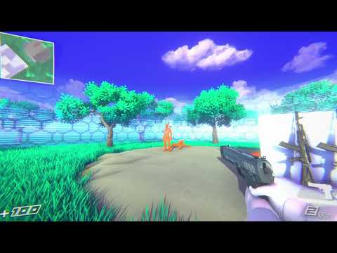
nice
credits for models:
"AK74M Assault Rifle" by creationwasteland
"Shooter: Revived - 9mm Pistol" by nyctomatic
"Gloves for fps game" by bobeer
I wanna have a similar effect that is just a circle/custom field around my playable area
well, you could just place a large transparent dome over it, and use a masked material.. Oh, or do you mean, not just a round shape, but conforms to a 'random' map?
does it make sense to do dirty tracking to prevent calls to MaterialPropertyBlock setters? or does unity already do dirty tracking inside those? (Sorry if this isn't the right channel, it seemed more appropriate than a general scripting channel, since its a graphics question)
that'd be the Depth Write setting
what you have open there corresponds to ZTest
I don't know what outline effect you're using, though, which means i'm guessing here :p
Given that the custom pass is only marked as requiring color and normals, that makes me wonder if it even cares about depth
i know very little about the gory details of those
Ok, thanks. that did not work, but it may have to do with the Lit shader in the first place, so i am attempting to adjust the Ztest on that. I copied lit, and made lit2, now hacking HLSL.
Here is the shader i am trying to get to work with transparency
https://github.com/federicocasares/cavifree
ah, it's curvature based
I am only using half of it, meaning i am only changing Cavity, not whitening Curves, but yes, two sides of the same coin
i spent way too much time and money on 'outline shaders' before finding this. this effect is what i was going for
judging from the the model looks, my guess is that there's no significant normal changes in your scene/model that could be picked up as outline. The curvature-based outline works best detecting sharp edges, give them smooth models and there will be no outline.
But, you can see the outline on the Thigh. it is meant to be a very subtle effect. it only does not show, where the material is a transparent shader, regardless that the vast majority of the material is opaque, the simple fact that it mode is transparent stops this shader from functioning on that material
you mean the outline pointed by the arrow? that's because it's comparing the normal on the ~~thing ~~ thigh with the normal on the background. The outline seems missing on the left thigh, thats because the post process failed to detect changes in normal direction
the leotard is the same angle, compared against the same background as the thigh. if i set thigh to transparent, it will not outline either.., or if i set leotard to Opaque, it Will outline
I see, there are two arrows 🤦 . Sorry I missed that. Seems like what Fen said, the transparant doesnt write to normal so the post process failed to detect the line.
No worries, you still had better theories than i did 🙂
Do shaders i make in Shader Graph 'bake' down to HLSL, .. my end question is, are Shader Graph shaders as performant as HLSL/'real' shaders?
does anyone know why my reflections are all pixilated in my scene?

nvm it was a reflection of a reflection somehow -_-
yes
The same algorithim in shader graph or written in HLSL is the same thing and will perform the same, but you have more freedom over the algorithim in hlsl which may make it perform better
It depends. Depending on the shader graph "template"(or whatever they're called), unity might include a bunch of extra code that you don't want in the final shader. For example, the lit shader graph would include everything related to lighting and shadows. If you don't want to use that functionality or calculate lighting/shadows yourself, that's obviously gonna add a lot of redundant processing. The shader lab shaders can also add extra code, but it's more controllable and you could avoid it all together as it's not as "automatic" as in shader graph. Other than that, yes a shader graph shader can be as performant as one written manually.
If you have some concerns, you can look at the final hlsl code generated by the shader graph.
Great explanation, thank you very much. makes perfect sense
Hi. Why would i make a texture atlas and mesh renderer? And the mesh have uv placed on certain parts of the part of the atlas?
Why not use sprite renderer and import the sprites individually, and pack it in editor?
The game is 3d environment
If your meshes are just quads, then a sprite renderer with a unity sprite atlas would definitely be enough.
Otherwise I don't really see how sprite renderer is related at all.
hey, does anyone know how/if a shader can write to a rendertexture?
I can elaborate if im not making sense
Yes. That's what they do usually.
sorry i know it goes to the cameras normal buffer
i mean some other buffer
the one that that unity doesnt default to
oops
Well, the normal way to do it would be to specify the camera to render to a render texture.
give me a second i think I can find an example
in these two talks they seem to have made a custom buffer to which they're writing (i think single channel) information to


I'm only assuming somewhere in the shaders they're writing to these buffers?
They mention post processing,so it's probably a full screen render pass. In unity it's achieved with Blit or a custom post processing effect. In urp I think you can create a full screen shader in the shader graph and add it via the render features.
If you need more control, you can probably use a render graph as well
I see, I think I've done that before, its just I remember having to put everything related on a certain layer so that those certain objects render
I'm not sure why exactly I don't like that approach, maybe just because I have to put things in the same layer but if I can't avoid it then oh well
Nah, that's not a Fullscreen pass.
it was using the command buffer if I remember correctly
either way it was a renderfeature
Perhaps a different effect. But if it was rendering objects separately, it's not a full screen pass. Full screen pass usually takes full screen data(for example gbuffer) and renders to every pixel on the screen.
Normal rendering is when you take a mesh, pass it through the vertex shader to get it's projection on the screen, then render only the pixels within that projection in pixel shader. Not the full screen.
It can involve extra draw calls if you need particular data for objects. But the last step is a full screen shader.
oh yeah it was that last part, I used the commandbuffer to render specific objects so I could process it to get the outline and blit it onto the rt for colour
it was fun figuring that out
I guess I'll stick to that method
Hey guys. is it possible to create an outline that will hilight objects only when another Mesh Render interfere? (But only GameObject Mesh Renderer, I'm currently using this package: https://assetstore.unity.com/packages/tools/particles-effects/quick-outline-115488 and problem is that it activates also if I'm spawning meshes using Particle System or VisualEffect - and I wanna avoid it)

Use the Quick Outline tool for your next project. Find this and more particle & effect tools on the Unity Asset Store.
Yes possible for sure by making use of depth testing, not sure what you mean about the particle systems though?
If I spawn any mesh using particle system or Visual Effect this outline is still being activated
And I want to avoid this because its adding unecessery visual noise
Ah I see but doesn’t this outline work by maybe adding an outline component? Can you just not add that component to the particle system? Or make it selective by using layers or something? I’m not sure how it works exactly for that specific asset.
So as far as I know. This works that you add Outline component to object where you select options how outline on this specyfic object will work and after you hit play it creates new material that is being added on top of the normal one
So that you have two materials (one - your selected; second - outline)
So I dont have any option for component to work only on specyfic layer
I have only option to limit on what type of object outline will be added
So you can only add the outline on the mesh renderers you want and not on the particle systems? I don’t really get the issue sorry
How can I make the grid pattern on different cubes match?

I can add outline to the particle system but this means that particle meshes will be hilighted if something is in front of that particle mesh
The simplest way is to use a triplanar mapping shader/material
This will only look good on axis-aligned boxes/planes though (only 90 degree rotations)

how can i get the noise to move along the x or y axis
and not the whole model
got something pretty good rn

Move based on what?
You can plug something from the Time node to the noise UV, for example
anything time or a variable
just not sure how to

still a little confused
UV determines where the noise is sampled
It's a vector2/float2
So there's your X and Y coordinates
works now ty ❤️

do you know how i could make a path through it
pretty bad screenshot but i have a path going through

Path defined by a list of points?
I would probably do that in a compute shader, haven't really done such things in a regular shader
straight through the middle with preferably a set value for the width
So just a line?
well i'd make it curved eventually
but ur right its probably best in a compute shader
i want to make a shader where i can overlay a shine effect that scrolls over a nine slice ui image. i have a hard time finding information about how i would do that though.
sounds like something you'd do with an animation i might be wrong though
try changing the color based on position and then offsetting that position with a time node
I was imagining a cartoony sort of line that moves over the image
That's definitely doable in a shader with a bit of math
yeah this is what im thinking. it is hard to do over a nineslice though and i havent found much info about the process of doing it.
i tried looking into the shiny effect for ugui repo but it seems to be using a parts of another repo that several years in the future compared to that one and i have not found the base class for the shine effect for example. which makes it hard to figure out the effect itself.
Is there a way to get the camera screen view in "Canvas Shader Graph" and use it as texture to create a simple blur effect ?
anyone got good learning resources for compute shaders?
as mentioned, a tri-planar shader would do it, but i would go the UV manipulation route, with tiling textures
hi there, im newish to shaders and was wondering if tutorials for unity from like 3-4 years ago would be deadly out of date, specifically for shaders?
wondering just before i start working and realise that a tutorial im using is giving me wrong info
also im basically wanting to create something like this, obviously not the quality of this but just similar

i assumed that their using a shader
yea more like conform to a random map with a shield shader material like that
heya, I'm working on a water shader with a pixel art aesthetic (original I know) and I was wondering if there was a way to get a "static" version of depth? right now as my camera moves forward and back, the depth values change in this pond for instance, let me see if I can get a video


ideally I'd like it to stay the same so as you move around the water doesn't shift weirdly
Yeah, that is a bit more complex. but, if you get to the point where you can actually make the randomized map (procedural) you should, by then, have a better idea of how to do the shield
I have some info about this here where I do an alternative calculation

💦 A huge, step-by-step tutorial on how to create a beautiful stylized water shader in Unity using Shader Graph. This works with Unity's Universal Render Pipeline (URP). Includes colors, foam, refraction, reflections, caustics and Gerstner waves.
oh geez, thanks so much, this looks very helpful
long shot here, but would you happen to know how to integrate your method into an orthographic perspective? I have to use the method shown in the picture to make the normal method for a depth fade work in orthographic, and I can confirm yours works with perspective, but I'm having trouble adjusting them to work together with orthographic (including the worldspace depth option, that is)

ah, there we go

Hi @regal stag I've been following this https://www.cyanilux.com/faq/#sg-drawmeshinstancedindirect for how to use DrawMeshInstanced working in shadergraph. Did the same exact setup, but I've found a quircky issue, maybe you can help me understand what's wrong?
If i setup the matrices in #pragma instancing_options procedural:vertInstancingSetup as stated, the instances fly all around they just flicker everywhere on the screen like if Unity_instanceID was a single value per draw call, or there's something corrupt with the matrices. However, if I move that exact code into a single method called right after the instancing_options procedural: thing, things work as intended. Any idea on what could that be? or why
List of frequent (or interesting) questions I've answered
Here's the vertInstancingSetup btw
void vertInstancingSetup() {
#if defined(UNITY_PROCEDURAL_INSTANCING_ENABLED)

    #ifdef unity_ObjectToWorld
    #undef unity_ObjectToWorld
    #endif

    #ifdef unity_WorldToObject
    #undef unity_WorldToObject
    #endif

    int instanceIndex = _Indices[_Counters[_LODValue].startBase+unity_InstanceID];
    InstanceData data = _PerInstanceData[unity_InstanceID];

    float4 rotation;
    float3 scale;
    UnpackRotationScale(data.quaternionScale, rotation, scale);
    float4x4 trs = transpose(MakeTRSMatrix(data.position, rotation, scale));

    unity_ObjectToWorld = trs;
    unity_WorldToObject = inverse(trs);

    #if SHADERPASS == SHADERPASS_MOTION_VECTORS && defined(SHADERPASS_CS_HLSL)
        unity_MatrixPreviousM = unity_ObjectToWorld;
        unity_MatrixPreviousMI = unity_WorldToObject;
    #endif
#endif
}
it's weird that it works in a standalone method, but here's also the matrix creation
float4x4 MakeTRSMatrix(float3 pos, float4 rotQuat, float3 scale)
{
    float4x4 rotPart = QuatToMatrix(rotQuat);
    float4x4 trPart = float4x4(
        float4(scale.x, 0, 0, 0),
        float4(0, scale.y, 0, 0),
        float4(0, 0, scale.z, 0),
        float4(pos, 1));
    return mul(rotPart, trPart);
}

float4x4 inverse(float4x4 input)
{
    #define minor(a,b,c) determinant(float3x3(input.a, input.b, input.c))
    float4x4 cofactors = float4x4(
        minor(_22_23_24, _32_33_34, _42_43_44),
        -minor(_21_23_24, _31_33_34, _41_43_44),
        minor(_21_22_24, _31_32_34, _41_42_44),
        -minor(_21_22_23, _31_32_33, _41_42_43),

        -minor(_12_13_14, _32_33_34, _42_43_44),
        minor(_11_13_14, _31_33_34, _41_43_44),
        -minor(_11_12_14, _31_32_34, _41_42_44),
        minor(_11_12_13, _31_32_33, _41_42_43),

        minor(_12_13_14, _22_23_24, _42_43_44),
        -minor(_11_13_14, _21_23_24, _41_43_44),
        minor(_11_12_14, _21_22_24, _41_42_44),
        -minor(_11_12_13, _21_22_23, _41_42_43),

        -minor(_12_13_14, _22_23_24, _32_33_34),
        minor(_11_13_14, _21_23_24, _31_33_34),
        -minor(_11_12_14, _21_22_24, _31_32_34),
        minor(_11_12_13, _21_22_23, _31_32_33)
        );
    #undef minor
    return transpose(cofactors) / determinant(input);
}
it's like if unity_InstanceID was always 0?
ooooooh wait a sec, i think i see now
nope, i thought maybe it's not compatible with material properties
but I also tried the setting manually throguh set material and nope
so yeah, nothing is set, unity_InstanceID is 0 and the buffers have the wrong data
Not sure really. It's been a while since I've used it, so is possible it's just broken. Or slightly different per pipeline (was written for URP)
It's really weird, honestly it just looks like when doing this call on the procedural isntancing options side, none of the data is set, but I can make it work just fine after.
Do you have any idea on what I could look into?
If it works in a different function could just keep it there and ignore the instancing_options stuff
heya, is anyone aware of a way to exclude a given layer or object from being drawn to the opaque texture (without making it transparent)? as shown I've found a way to get pixel thin outlines on my water using viewspace normals, but if the shader is transparent, it doesn't write to the normals texture itself, and if it's opaque it blocks the stuff under it from being drawn to the opaque texture

alternatively, can I draw a transparent shader to the camera normals texture somehow?
I could do that, but i find it really weird that I still need, at least, a dummy method or otherwise it throws errors
found it for those in the future- need to set SSAO "after opaque" to false as that's what requests the creation of the normals texture
Hey for some reason with a full screen render pass I can't get any depth info. With simply
half4 frag(Varyings IN) : SV_Target
{
    return SampleSceneDepth(IN.texcoord);
}
And including Core.hlsl, Blit.hlsl, and DeclareDepthTexutre.hlsl, the return of SampleSceneDepth is 0 across the board.
I went into the frame debugger and the depth texture is visibly there in grayscale in _CameraDepthTexture so I have no idea why this isn't working.
I just have my custom shader linked to a material and that material linked as pass material on full screen renderer feature
I also tried just copy pasting https://docs.unity3d.com/Packages/com.unity.render-pipelines.universal@13.1/manual/writing-shaders-urp-reconstruct-world-position.html and nothing in my scene changes at all despite the _CameraDepthTexture looking correct in the frame debugger
Does it work if you return a dummy color(like 1,0,0,1)?
Recently updated our engine to Unity 6 and a lot of our transparent materials are rendering in front now. Anyone know how to fix? This face shadow mesh is supposed to be behind that blue mask

- Check if depth texture/map is enabled in the render pipeline asset settings.
- Try switching between forward/forward+/deferred rendering🤔
I just figured it out. It was on a ForwardRenderData setting on our render pipeline asset. The Depth Texture Mode was set to After Opaques and switching it to After Transparents fixed the issue
I found out that transparency doesn't render to the depth buffer so I figured I'd just mess with any setting that had depth haha

how to make simple water?
Hey, thank you for helping. Dummy color works. I have tried variations of scaling the output of SampleSceneDepth(IN.texcoord) and inversing it, and its always flat one color across the screen so I assume its 0.0 across the board for each fragment
Also when I remove the code SampleSceneDepth(IN.texcoord);, the frame debugger removes the depth texture image as an input.
Otherwise i get a depth texture as shown below allegedly being passed in as _CameraDepthTexture but then the sample still outputs 0.0 for every fragment. Very confusing

Try returning the uvs instead and see if that works as well
return half4(IN.texcoord, 0.0, 1.0); is all black
Then the texcoords are not set
What do you have in the vertex shader?
I am relatively new to shader programming. I intended to use the Blit.hlsl include as the vertex and have my own fragment, so my pass is
{
            HLSLPROGRAM
            #pragma vertex Vert
            #pragma fragment frag

            #include "Packages/com.unity.render-pipelines.universal/ShaderLibrary/Core.hlsl"
            #include "Packages/com.unity.render-pipelines.core/Runtime/Utilities/Blit.hlsl"
            #include "Packages/com.unity.render-pipelines.universal/ShaderLibrary/DeclareDepthTexture.hlsl"

            half4 frag(Varyings IN) : SV_Target
            {
                return half4(IN.texcoord, 0.0, 1.0);
            }
            ENDHLSL
        }
And vert is the name of the vertex shader in Blit.hlsl
Varyings Vert(Attributes input)
{
    Varyings output;
    UNITY_SETUP_INSTANCE_ID(input);
    UNITY_INITIALIZE_VERTEX_OUTPUT_STEREO(output);

#if SHADER_API_GLES
    float4 pos = input.positionOS;
    float2 uv  = input.uv;
#else
    float4 pos = GetFullScreenTriangleVertexPosition(input.vertexID);
    float2 uv  = GetFullScreenTriangleTexCoord(input.vertexID);
#endif

    output.positionCS = pos;
    output.texcoord   = uv * _BlitScaleBias.xy + _BlitScaleBias.zw;
    return output;
}
Hmm... Relying on unity macros and functions without knowing what they do is a bit unreliable. Did you confirm all the API in the documentation? Or read through the macros/functions code?
Are you following some kind of docs that specify how to use these includes/macros/functions?
Hey, im having the issue that when I create my own shader that I made with ShaderGraph and add it as a material to my character rig that uses Sprite Skin im getting the following warning:
WalkRig is using a shader without GPU deformation support. Switching the renderer over to CPU deformation.
UnityEngine.U2D.Animation.SpriteSkin:OnEnable () (at ./Library/PackageCache/com.unity.2d.animation/Runtime/SpriteSkin.cs:376)
When using CPU deformation(Not doing anything just letting the warning stay) the shader works kinda junky, the rig position is in the corner and the borders of the rig elements are scaled down to least edges, so not quite an option for me. So my question is how can I make my shader work with this "GPU deformation". My idea was just to see what the "Sprite-Lit-Default" makes and copy its nodes that are responsible for that and thats it, however im not quite sure on how to open the built-in shader with ShaderGraph and if its even possible. But open to other solutions too 
Copying this over from the VRChat discord. It is very baffling.
I am writing a shader that reads the position of a light in the vertex stage (this is the only reasonable way to get an object's position in a shader in VRChat, since you can't write your own scripts).
To find the correct light, I check the alpha value of the light's color.
Two friends of mine with AMD GPUs are having problems seeing the effect. Here are two very similar blocks of HLSL:
bool alphaGood = distance(unity_LightColor[idx].a, 0.64) < 0.01;
bool rangeGood = distance(unity_LightColor[idx].a, 20) < 0.01;

bool which = alphaGood || rangeGood;

if (which)
{
    lightPos.xyz = float3(unity_4LightPosX0[idx], unity_4LightPosY0[idx], unity_4LightPosZ0[idx]);
    lightPos.w = 1;
    break;
}
This one works fine. 20 is a totally arbitrary number. I can choose any number I want that is not 0.64
bool alphaGood = distance(unity_LightColor[idx].a, 0.64) < 0.01;

bool which = alphaGood;

if (which)
{
    lightPos.xyz = float3(unity_4LightPosX0[idx], unity_4LightPosY0[idx], unity_4LightPosZ0[idx]);
    lightPos.w = 1;
    break;
}
This one does not work.
People with AMD GPUs always seem to wind up with which being false here in the second example
The first example compiles to this:
  14:   add r2.xy, l(0.640000, 20.000000, 0.000000, 0.000000), -cb0[r0.w + 7].wwww
  15:   lt r2.xy, |r2.xyxx|, l(0.010000, 0.010000, 0.000000, 0.000000)
  16:   or r1.w, r2.y, r2.x
  17:   if_nz r1.w
The second example compiles to this:
  14:   add r1.w, l(0.640000), -cb0[r0.w + 7].w
  15:   lt r1.w, |r1.w|, l(0.010000)
  16:   if_nz r1.w
This makes absolutely zero sense.
to clarify -- rangeGood was part of an insane hypothesis that the light's range would be stored in the alpha value (it was not). It's a totally bogus comparison and it's always false.
I verified that only alphaGood is ever true by passing the result on to the fragment stage and outputting that
I guess I'm hoping someone has seen something like this before and can suggest why it's like this
Loosely following https://docs.unity3d.com/Packages/com.unity.render-pipelines.universal@13.1/manual/writing-shaders-urp-reconstruct-world-position.html. When using URP are you not supposed to use rely on their pipeline functions?
How do I get the terrain to accept more than 8 light sources? I'm using forward+ and I've got more up to 25 light sources from underglow and headlights on each car. As a result, the terrain is no longer illuminated by the sun
The road the cars traverse on is being illuminated properly by all the lights, the only thing being weird is the terrain
Forward+ does not have a per-object light limit. And usually, the main directional light is stored separately from "additional" lights and is always applied.
Which shader is the terrain using?
Default unity terrain shader
For URP? Universal Render Pipeline/Terrain/Lit?
in shader graph
is there a way to apply the object space normal vector node as texture then offsetting it
just connecting object space normal vector node to base color it is applied like textures but I want to offset it to get the same effect of offsetted texture when you change its uv
Yeah, that one
Okay, no. Something else is wrong with my scripts
I hate coincidences like these
Sorry and thank you for your time
If I understand you correctly, then no. It's easy to sample a different part of a texture at any pixel, but it's not possible to sample a different interpolated vertex attribute than the one already calculated for each pixel.
If you explain why you need this, what effect you're going for, maybe there is another way to achieve it.
yeah I think you understand what I mean
Can I take a video? Because I think I'm going insane
Yes, as long as it's under 8 MB, you can upload it directly here.
thought of trying a new method of normal edge detection to add edge outlines by offsetting the normal vector as if it was a texture then getting the difference between the original and offsetted normal vector texture , it should get the edges if that was possible
While it's not trivial to offset a vertex attribute by any amount, it is possible to sample the difference between two neighboring pixels, by using the DDXY node.
You can put any variable into it and you'll get back a value that corresponds to how different the variable is for the two pixels next to this one in XY screen space.
It's never behaved this way before. Both lights were working were able to light the scene on their own without the other being enabled now all of a sudden they can't illuminate without the other being active
Both? Do you have two directional lights?
Yeah
I've finally sent the video after fighting discord upload
It's possible that multiple directional lights have not been fully implemented in Forward+. More than one directional light is not usually recommended. In Unity, only one directional light can cast shadows.