#archived-shaders
1 messages · Page 94 of 1
I'm pretty sure the compiler will flatten these branches anyway, since it would otherwise have problems getting the derivatives
You could throw on a [flatten] attribute, I guess
i fixeed it thru manual derivative calculation
Well, I don’t think the refraction is the hard part here. The thing with diamond is that the IOR is so high most of the light rays will do many total internal reflections which obviously doesn’t sound like easy thing to achieve in realtime applications. There must be some cheap trick to fake it well enough that I’m not aware of but actually getting the reflections and refractions accurate doesn’t sound fun at all
Yeah, that's what I was thinking of there
the repeated internal reflections
I saw someone comment that they baked the face normals onto a sphere, then raymarched to bounce around inside of that sphere until they could escape
Interesting approach, I think ray tracing against the sphere should be easy enough too. Depends on many things of course but that obviously might be too slow on some uses
I guess "ray marching" is the wrong term, yeah
you can directly compute the intersection
I last did raytracing in college in 2015 😛
and i haven't done raymarching for something like SSR before
In this case simple ray-sphere intersection should do
Now that I think about it, I don’t think that would be too expensive if the max reflection count is set reasonably low and the loop maybe even unrolled. If the accuracy isn’t of top priority, maybe all branching could be eliminated by always calculating x amount of reflections regardless of the reflection angles. It’s really hard to guess what effect any modification would have to the visual appearance without trying but there must be some way to get decent diamond visuals without sacrificing too much on performance
where can i learn more about depth buffer shenanigans, and why does force enabling depth write fix what seems to be backface culling issue / is this the right way to do that?
This shader should not be transparent
tysmm
So I have a forward renderer that hides the standard objects in the scene, and renders over them with a material that's technically transparent, but usually has opacity set to 1. But objects behind are still visible and the depth seems all wonky.
The depth is fine when I have the original (opaque) objects being rendered, or when I change the shader to be truly opaque and not transparent. Problem is, sometimes I do need the material to be transparent.
Is there a way I can force a depth pass without rendering the underlying objects, or should I use a truly opaque version of my shader for all the bits that I know will be opaque?
I tried setting the forward renderer's depth texture mode to 'force prepass' but I guess it still only renders depth for stuff included in the layermasks
since I want to use the same material, is there a way to have a material be either truly opaque or transparent, without changing the shader? Or do I need to make two shaders that are functionally identical except that one supports transparency and the other doesn't?
@dim yoke @warm pulsar I feel like you could cheat a lot by reflecting the reflection probe but bending the vector an arbitrary number of times to mimic the internal reflections
Maybe blend in another cubemap for some extra "brilliance"
transparent rendering is different to opaque. Transparent objects dont normally write depth or test it (they test depth but only ofc with the opaque objects that wrote to depth previously)
why am i getting Assertion failed on expression: 'SUCCEEDED(hr)' when i try to dispatch a compute shader with "relatively" large computebuffer (of size 1024x1024x16 = 16mb) ???
I'm very new to shaders. I'm trying to add the ability to "assign" a sprite texture (and UVs) to a base shader code I have. But I'm not even sure what the property I'm looking for (applying the texture sprite) is called
Does anyone know what's it called? With a name, I can Google...
You use a texture property with the _MainTex reference to obtain the sprite texture
Danke! Something to do tonight/tomorrow 🙂
Um what am i missing i am trying to display a texture on Planet made from blender i got it show but when i try to blend between another texture using Triplanar I just get a white Sphere if i adjust the height one disappears i guess.

I dont think my start and end wTF.. forgot to connect the start and end to the second Smoothstep let me try that..
Nope damn i thought i had it..
Whatever that is, looks like could be simplified a lot by using subgraphs to reuse common groups of nodes
Hey guys, if I have this output, how can I turn it upside down?

One minus
Assuming the value is in the 0-1 range

Hello, I was trying to create a shader for laser in unity, but i have one issue which is that the laser's texture speed changes based on laser's length, if laser is short speed is slow, and if laser is longer speed becomes fast. how can i counter it?

okay i noticed it's not the speed which is changing but the laser texture gets stretched. any fix for that?
sorry for the screenshot but I don't want to spam with messages here :s

can i make this take in a material instead?
and than the texture of the face
so the material will be a skin color
a material uses a shader
can you explain what you're trying to accomplish?
Oh boy outlines
have a pixel art face rendered on top
So one option is to completely re-render the highlighted objects
weird thing is the outlines aren't the hard part lol
so, kind of like putting a sticker onto a surface?
yeah
but still having full control over everything
like u know when i modify a material
If you want it to be dead simple you could consider having a second submesh
change color, smoothness etc
stick a plane where the face belongs and just render a second material there
there is gonna be flickering
yeah
Unfortunately you can't easily "compose" shaders (like you can in Blender with the Mix node)
i mean it would work
how did unturned and other games do this do u think
like battlebit remastered

i duplicated the face
and just pasted it there
how come there isnt any flickering?
last time i did it there was
Z-fighting can be very fickle
someone knows how can i make this surface shader (BIRP) receive shadows?
Shader "Custom/SimpleFoliage" {
    Properties {
        _MainTex ("Texture", 2D) = "white" {}
        _Color ("Color", Color) = (1,1,1,1)
        _Cutoff ("Alpha Cutoff", Range(0,1)) = 0.5
    }
    SubShader {
        Tags { "Queue" = "Transparent" "RenderType" = "Transparent" }
        LOD 200

        CGPROGRAM
        #pragma surface surf Lambert alpha:fade addshadow
        //#pragma surface surf Lambert alpha:fade addshadow alphatest:_Cutoff

        sampler2D _MainTex;
        fixed4 _Color;
        float _Cutoff;

        struct Input {
            float2 uv_MainTex;
        };

        void surf (Input IN, inout SurfaceOutput o) {
            fixed4 tex = tex2D(_MainTex, IN.uv_MainTex) * _Color;
            clip(tex.a - _Cutoff); // Clipping for transparency
            o.Albedo = tex.rgb;
            o.Alpha = tex.a; // For blending transparency
        }
        ENDCG
    }
    FallBack "Transparent/Cutout/VertexLit"
}


yeah I think the easiest solution might be to just have two versions of my material, that are identical except for one being opaque and the other being transparent. Then all the stuff that doesn't need to be transparent can be rendered first using the opaque material, so a proper depth pass is put in place
Or alternatively I could have a dead simple opaque material rendered first over everything that needs to be opaque, that serves no purpose except to give some geometry for a depth pass to be made with. Then I can render over everything with my one transparent material, but it'll have actual depth values to work with
iirc, transparent shader cant receive shadow, there was a work around by replacing the "alpha" with "decal:blend" but I'm not sure if it's still work now
or, you can just use alphacutout instead
im trying to achieve a look similar to this. basically, the leaves cast and receive shadows. im not sure if there's an easier way. if you know any

alphacutout is the easier way, it also safes you from headache fixing the transparency overlaps
Is there a way to iterate through all active renderers, that's more performant than using a for loop on FindObjectsOfType<Renderer>() every frame?
cache them on a list on start, and add when a gameobject with renderer spawned, and remove one when a gameobject is destroyed?
also this should go to #archived-code-general instead
I asked here in case there was something built in
I meant to ask in #archived-urp but didn't realise I was in the shader channel
Hi it seems shader graph does not support z offset which I need for parallel surface issues. But maybe a custom function can do the equivalent?
Don't think so. One of the very frustrating limitations...
You can offset the vertices, but definitely not ideal
Also with a shader graph can you not expose some of the Surface options you see on a normal material so you can have one material be double sided and one not with same graph?
yes possibly can use view direction to offset though, but the docs seem wrong on this being normalized yet it is not length 1 which is weird... Edit - is ntot wrong but is weird to view as has little effect in object space
This works if you subtract the view direction times a small amount in object space
Render the meshes with a solid color (your outline color) to a buffer (so you get a silhouette), then dilate that buffer (blurring, JFA or other dilation methods), then subtract the original silhouette from the dilated one to get your outline.
Example


And for URP to draw every mesh to a texture, using RenderGraph API that is using
RasterGraphContext.cmd.DrawRendererList(RendererListHandle);
And use
builder.SetRenderAttachment(customBuffer, 0); to configure it to render to a custom buffer
Hi people. Im building a vrc world (so unity builtin) and baked lighting. And I cant manage to make most water shaders work properly. Material just fades out from a small distance. Ive notices that it depends on Cameras near and far clip plane. It works only only when near clip is kinda big so its not the way out.
Did someone had same problem ever?

In shader itself I tried searching for something like clip and found this:
            ase_screenPosNorm.z = ( UNITY_NEAR_CLIP_VALUE >= 0 ) ? ase_screenPosNorm.z : ase_screenPosNorm.z * 0.5 + 0.5;
            float eyeDepth167 = LinearEyeDepth(SAMPLE_DEPTH_TEXTURE( _CameraDepthTexture, ase_screenPosNorm.xy ));
            float temp_output_168_0 = ( eyeDepth167 - ase_screenPos.w );
You can. In the graph settings check 'expose settings' or something like that!
Took me a while to find that as well for my assets. The downside is is that it doesn't allow you to point to which to show and which not to show. For that you need a custom inspector script I think
I have an unlit shader in shadergraph, (in unity 2022), but it doesn't really work properly as a mask, or when being masked (mask treats it as a full rect, and doesn't get masked at all). What options should I look into to fix this issue?
But direction based Z offset for vertices is possible but rough for sure
Is it opaque? Maybe that matters.
Is it for 2D sprites or for UI?
UI shaders are officially supported in Unity 6, so maybe upgrade if that's the case
transparent, for UI, but in unity 2022 there isn't a difference between ui and 2D in 2022 as far as I know
yeah... that might be the way to go
Yeah for UI you likely need canvas shaders from 6
🙃 I'd rather avoid that if I can, but oh well...
Canvas is definitely different from non canvas 2D as far as I know
6 actually is quite nice to work with from my experience :P
Ah - is called Allow Material Override! Not so obvious...
Yepyep!
Is it possible to sample rendering layers as a mask in shader graph?
I went for another approach instead which works... fine, it's definitely not the best for performance on more detailed meshes but works for me: dynamically add/remove two materials to each mesh I want outlined, one to mask out the mesh in a stencil, and another to draw the outline where the stencil is not equal and extrude the vertex shader along the normal a bit

Aha so a vertex extrusion outline, looks good! Especially given the hard edges of you mesh. Have you smoothed the normals maybe?
yep!
One limitation I can think of is that alpha cutout example you showed (of the plant), but maybe that's not needed in your case.
Yeah there won't be any meshes like that in my game hopefully
hey peoples, I have a compute shader where every thread needs to loop through a structuredbuffer of uint, and upon finding an uint set to 0, set it to 1 then store the current index in another buffer, all without threads setting the same uint or skipping any
the function I'm running right now looks like this, but the result is wrong, with a bunch of early IDs being skipped, and one of the IDs being a super high number with the next IDs then being all 1s, any idea what could be the problem?


(the id being returned with +1 is not a mistake, 0 is meant to represent a failed allocation)
nvm fixed it, turns out I had to initialize the buffer data & it didn't auto initialize to 0
Hi, I'm trying to add some fake bottom shadows to this shader in shadergraph. Here's what I have so far.
I want the shadow ramp to always start from the bottom of the mesh, but turn upward regardless of rotation. If I set the Position node to World Space, the object has to reach a certain height before the ramp fades out. How do I achieve this effect? Thanks.

Use World space (or absolute world in HDRP), but also subtract the position from the Object node, which is the origin of the object - provided there is no static or dynamic batching (srp batching is fine tho)
Awesome thanks
This method seems to work in terms of setting the gradient in the proper direction, but for some reason, it's giving me a green overlay with the shadow gradient.


I have the Out of the Preview node going directly into the Base Color
You'd do the subtract before the Split node
or also Split the Object node Position port to take only the Y/G axis
Ohh okay, I see, thank you very much!
Hi I have a question someone knows where can I commision simple unity shaders?
This would happen in the vertex stage.
You can change the position of each vertex there.
You can take the current position from a Position node, add to it, and then run that into the Position output

you may need to use a Transform node to convert your displacement into the right space, though!
You're throwing out the current Y position entirely
Wait I can't read
That would make an object move back and forth on the object-space Y axis, yeah
Is this a terrain renderer, or are you using a bunch of little mesh renderers here?
this is a standalone object
but yeah, object space can be really funny

especially if your object naturally has a scale of 100
oh yeah, dupliverts from Blender
probably has a scale factor of 100, since that's what you get by default from an FBX export
A big thing with shaders is figuring out the correct coordinate space to work in
its parent 1 the child 7 then the leaves are all different
You want these objects to move up and down by a fixed amount, right?
well yes but thats just a starting point for a wind sg
So we have two important things here:
- "up and down" -- from what point of view?
- "a fixed amount" -- from what point of view?
if the point of view isn't from the object itself, then it sounds like you want world space
yes
that's where the Transform node comes in
here's how I'd do this
first, compute a vector that oscillates from [0,1,0] to [0,-1,0]
you can just plug Sin Time into a Combine node to do that
This is how much the vertex should move in world space
(You may want to scale it so that it's not a massive 2-meter range...)
Then, you need to transform this vector into object space

The resulting vector, when added to an object-space position, will cause it to move around properly
woops
also, this is a lot nicer than combining individual components together -- that's why I misread your shader at first
am I doing this wrong, why is it all white?

i made an unlit shader for a cel/toon shading effect, and im trying to add fog so my grass doesnt look terrible when it cuts off, but i cant manage to figure out how to do it. ill send a screenshot of the shader graph

lerp(base color, fog color, exp(-distance to camera / fog opacity))?
Guys, does anyone know a good UI blur shader that supports transparency? Either maskable or the one that follows the sprite's shape? (for example if the image is a circle, it only blurs in that circle)
I'm a little confused about shaders, as far as I know fragment shaders are called for every pixel rendered, but what about vertex shaders? At first I thought they're called for every vertex, but the vertex shader output is used in the fragment shader, doesn't that mean that the number of vertex shader calls should be the same as the fragment shader?
Vertex shaders do run on each vertex in the mesh. Each triangle produces multiple fragments ("rasterization" stage between the vertex and fragment) where data passed from vertex shader is interpolated over the triangle
the vertex shader outputs are interpolated over many fragments
it works and i figured out some logic to make it move more further down the branch ty
I have a question, does unity use GLSL, if not then what does it use for shader code?
HLSL
ah okay, thanks
I'm kinda new to scripting shaders, I thought unity used HLSL, but I saw some stuff using CGINC and I have no idea what that is
From my understanding cginc files are just HLSL that gets glued into your shader code
So you can share functionality between shaders
so like, imports?
Yep
I see, thanks
I think the compiler quite literally copy pastes their contents into the shader but I could be wrong here
kinda confused me because it looked like HLSL but wasn't named the same
I’ll try that
looking more carefully, should have swapped the colours in the lerp
Also fog opacity can be a colour too (I think orange is realistic?)
Woo I'm boutta make a name for myself

Trying to do Manga style shading, I think the crosshatch shading is a little too detailed might have to tone it down
But also, does anyone have experience drawing lines where "sharps" are on an object? Like where there are 2 verts at the same place with a different normal?
Obv can't be done with frag shaders, probably a render feature? But I'm unsure where to begin
If you can access the fullscreen normals somewhere, you could compare the current pixel's normal with its neighbors and detect sharp changes 🤔
Probably would need to use the scene depth too, to avoid comparing pixels that are actually far apart in the Z axis
Is this for like, edge detection?
Uh nah, I hate texturing and I wanna make lines where things like folds/creases are on the character.
I'm also working on a custom normal thing that can switch between presets of normals/vertices at runtime so I can change where these fold lines appear
I just wanna draw lines along these sharps, if I can do that I can figure out making the lines tapered or whatever later
Full screen normals sounds like the way to go probably. I was sitting here thinking of some ridiculous solutions 😅
I wanna make lines where things like folds/creases are on the character.
The implementation would probably be somewhat similiar to screen space ambient occlusion
Just to give you some keywords to google etc.
I have made a laser in unity using line renderer, but does anyone have any idea on how to make it progressing like this laser fired moves around until it reaches the final point?
Assuming you want to do it in shader, you could simply set Texture Mode to Stretch and set alpha to uv.x > progress (or <) where progress is the perfentage of the line that should be filled
In C# script you could modify the points of the line renderer to make it appear as if it travels slowly without using shaders. You need to keep track of the progress of the lasers anyways in your script if you want the interactions with the lasers to only fire when the laser reaches the object in question (like the batteries only enable when the laser reaches it)
also need to keep track of the length of the line (either in script or shader) so that it doesn't progress faster for a longer line
@primal prawn I would honestly rather do the line animation on C# side. Having one material per laser (or MaterialPropertyBlock) to pass them different properties doesn't sound very fun thing to manage. You have to keep track of timings and stuff on C# anyways so might as well do the animation too. I have no idea how cheap or expensive it is to update line renderers points every frame during the animation but it surely can't be that bad especially when the lines only consist of couple points
Thanks, I was actually thinking the same, but applying it was messing with other stuff in what I was planning to do but fortunately now it works well just getting a little bit of bugs sometimes
Maybe i need to improve my problem solving skills 😶🌫️
is it possible to view only shadow maps in unity ? something like this

Is that for an actual game or just for debugging in editor?
debugging ofc
Can someone explain how I can switch between different shader passes?
Pass
{
  Name "Sprite Lit Gradient Linear Alpha"
  //shader code...
}

Pass
{
  Name "Sprite Lit Gradient Linear Premultiply"
  //shader code...
}

Pass
{
  Name "Sprite Lit Gradient Linear Multiply"
}

Pass
{
  Name "Sprite Lit Gradient Linear Additive"
}

//later...
CustomEditor "BlendModeShaderGUI"
Then I have a custom editor, and I'm doing material.SetShaderPassEnabled, which correctly debugs if I use the following:
StringBuilder sb = new ();
for (int i = 0; i < material.passCount; i++)
{
    //Add pass name, and if it's enabled
    sb.Append(material.GetPassName(i));
    sb.Append(" ");
    sb.Append(material.GetShaderPassEnabled(material.GetPassName(i)));
    sb.Append("\n");
}
Debug.Log(sb.ToString());
But it doesn't seem to have any effect at all on the way the shader looks, even though it should look drastically different.
Rendering Debugger seems to have some mode related to shadows, take a look
The custom editor
#if UNITY_EDITOR
public sealed class BlendModeShaderGUI : ShaderGUI
{
    public override void OnGUI(MaterialEditor materialEditor, MaterialProperty[] properties)
    {
        Material material = materialEditor.target as Material;

        // Find the blend mode property
        MaterialProperty blendModeProp = FindProperty(propertyName: BlendModeExtensions.BLEND_MODE_PROPERTY_NAME, properties: properties);

        // Display the dropdown
        BlendMode blendMode      = (BlendMode)blendModeProp.floatValue;
        blendMode                = (BlendMode)EditorGUILayout.EnumPopup(label: "Blend Mode", selected: blendMode);
        blendModeProp.floatValue = (float)blendMode;

        // Apply the blend mode keyword
        SetBlendMode(material: material, blendMode: blendMode);

        // Draw the default properties
        base.OnGUI(materialEditor: materialEditor, properties: properties);
    }

    private void SetBlendMode(Material material, BlendMode blendMode)
    {
        // Disable all "Sprite Lit" passes
        foreach (BlendMode mode in Enum.GetValues(enumType: typeof(BlendMode)))
        {
            material.SetShaderPassEnabled(passName: mode.ShaderPass(), enabled: false);
        }

        // Enable the selected pass
        String passName = blendMode.ShaderPass();
        material.SetShaderPassEnabled(passName: passName, enabled: true);
    }
}
#endif
what is "Rendering Debugger" ?
which render pipeline are you on?
Window/Analysis/Rendering Debugger
I mean this seems to be the only thing I'm getting out of the Rendering Debugger (the lightmap texture itself) which is not what you wanted anyways

yep
but what you can do quite easily on BiRP is to create a shader that only renders the shadows black and white and use Camera.SetReplacementShader to render everything with the same shader
how so?
idk, harder than having a lovely button to toggle off/on for quickly seeing stuff
sure, but not the hardest thing in the world either
you could make your own editor script and make it be a button too
yea
Would you like to have that on the scene view camera, in game camera or both?
I can try if I can get it to work
cuz im doing it whatsoever rn
thank u

it will be very difficult to make it support many stuff tbh, given that transparency exists etc.
does anybody have an idea, why this could be happening, I am going feral

but it's a shader graph, I didnt code anything lmao
yeah just saw that too, i have no idea about shader graph sry
ah, no worries, thank you for trying to help anyways :)
my guess is there's a node in the graph that unity let you wire the wrong thing into (or even a lack of a wire that a node requires)
even if I create a new shader graph, that's completely empty, this is still happening
how strange!
I really cant see how, but maybe that hlsl file somehow got altered in some way
which doesnt make sense as it comes from the unity packages
it's the same exact loc, i cant wrap my head around that error
wish I could help, as unhelpful as that is to say 😅
haha, no worries, I am completely confused by that error too, and I couldnt find anything useful in forums
but hey, youre at the top of google!

haha, that's good to hear
try uninstalling the shadergraph package and reinstalling it
maybe some data got lost in the tubes when you installed it before
I'll try that, though I have even tried to migrate to a new project, and it's still happening
is it possible to modify shadow intensity (blacker shadows) in a surface shader ? aka read shadowmap and mult the albedo over the existing shadow
Something like this seems to work but I don't think I'm able to do the custom shader though. With the help of the example shader in the documentation https://docs.unity3d.com/Manual/built-in-shader-examples-receive-shadows.html I got the main light shadows working no problem but additional light shadows and transparent object shadows seem to be out of my ability. I can't find any good resources on them either so I think I have to give up on that.
[MenuItem("Tools/Draw Shadows Only #e")]
public static void ReplaceShader()
{
    Shader shadowsOnlyShader = Shader.Find("Your Shader Name");

    foreach (SceneView sView in SceneView.sceneViews)
    {
        sView.SetSceneViewShaderReplace(shadowsOnlyShader, "");
    }
}

[MenuItem("Tools/Disable Shadow Rendering #r")]
public static void ResetShader()
{
    foreach (SceneView sView in SceneView.sceneViews)
    {
        sView.SetSceneViewShaderReplace(null, null);
    }
}
``` ~~(modified to fix couple problems)~~I've got a quick fix for it, but it's quite annoying, I can build the game, but only if I haven't compiled a shader in that current editor session, if I did that, I'd have to restart the editor and then I can build the game again. Really weird, but as long as it works for now, it's fine.
how would someone go about modifying ambient light contribution in a surface shader?
is it even possible ?
Can someone assist me in creating a UV solution that projects a flat image on the skybox? I want to use it for moving clouds
It would be something like this

I want these inputs to show up in the "Surface Inputs"

They are plugged into a custom function block, in the string setting.
the custom function then plugs into base color.
Is that even possible?
or is it not, and a punishment for me using shader graphs instead of amplify
As in on the material? To do that you'd create properties in the Blackboard window.
https://docs.unity3d.com/Packages/com.unity.shadergraph@17.0/manual/Blackboard.html
(Then drag the properties into the graph and connect them to the inputs on the custom function)
Ambient lighting is passed to the shader in the form of spherical harmonics and is combined with data from light probes if the scene has any. So, you can't change the contribution of ambient light separately from light probes.
At some point in your shader, a call to ShadeSH9 (for built-in) or SampleSH9 (for srp) is made, which will sample the spherical harmonic and return the combined ambient and light probe color for the given normal.
The ambient probe can be modified globally with RenderSettings.ambientProbe.
what i'm ultimately trying to do is get shadows to be darker on the said models with the shader. maybe there's another way and i'm over complicating it. what do you think
Do you care about light probes working with this shader?
currently no, but wish to keep it if possible i mean
It's always best to try to remove the contribution from the source rather than artificially making it darker after the fact. Since ambient color is combined with light probes, your only option to the reduce the contribution of both. I assume you're never calling Shade/SampleSH9 yourself, it's probably done as part of a larger lighting function that you're using, either surface shader or Shader Graph. That means you either need to deconstruct the lighting function you're using so you can do each step manually and modify the result from SH9, or you can try to use some macro magic to redefine Shade/SampleSH9 to your own modified version before it gets called.
i see i see. currently im using a modified blinnphong, but i can't see where or how could i modify the said shade step?
#pragma surface surf CustomMobileBlinnPhong addshadow
        inline fixed4 LightingCustomMobileBlinnPhong (SurfaceOutput s, fixed3 lightDir, fixed3 halfDir, fixed atten)
        {
            fixed diff = max (0, dot (s.Normal, lightDir));
            fixed nh = max (0, dot (s.Normal, halfDir));
            fixed spec = pow (nh, s.Specular*128) * s.Gloss;

            fixed4 c;
            c.rgb = (s.Albedo * _LightColor0.rgb * diff + s.Albedo * _LightColor0.rgb * spec) * atten * 2;
            UNITY_OPAQUE_ALPHA(c.a);
            return c;
        }
is there a pragma for it or sth
obviously the lighting model doesn't touch that
Oh, with a custom lighting function in a surface shader, you fully control the lighting. Since you're never calling ShadeSH9, the scene's ambient probe is not contributing to the lighting. There shouldn't be any ambient color here, that I can see.
Maybe the specular color is adding something that resembles ambient
returning black would still make the mesh retain color affected by the ambient light
so the lighting function isnt doing anything at all, the ambient light is added after or before
they are separate
Oh, apparently there is a noambient you need to add to the surface pragma line to prevent that
Then you'll need to call ShadeSH9 yourself and add it to the result
interesting. so if i disable ambient i call ShadeSH9 in my lighting model ? how do i do any of these ?
the flag noambient over the pragma surface worked.
but light for some reason doesn't seem to get multiplied. am i doing it wrong?
#pragma surface surf CustomMobileBlinnPhong noambient addshadow
inline fixed4 LightingCustomMobileBlinnPhong (SurfaceOutput s, fixed3 lightDir, fixed3 halfDir, fixed atten)
{
    fixed diff = max (0, dot (s.Normal, lightDir));
    fixed nh = max (0, dot (s.Normal, halfDir));
    fixed spec = pow (nh, s.Specular*128) * s.Gloss;

    // Add SH9 ambient lighting
    fixed3 shAmbient = ShadeSH9(float4(s.Normal, 1.0));

    fixed4 c;
    c.rgb = (s.Albedo * _LightColor0.rgb * diff + s.Albedo * _LightColor0.rgb * spec) * atten * 2;
    c.rgb *= shAmbient;
    UNITY_OPAQUE_ALPHA(c.a);

    return c;
}
The ambient light should be added to the result, not multiply it.
i get completely white models
i should feed it the normal right ?
Yes, it looks correct. Maybe try normalizing s.Normal, but I'm pretty sure it should already be normalized.
i tried
No sorry, the ambient needs to be added to the light color, and the combined result should then by multiplied by the albedo.
It's best to create a separate variable that represents the light for this pixel.
fixed3 diffuseLight = (_LightColor0.rgb * diff * atten) + shAmbient;
fixed3 specularLight = _LightColor0.rgb * spec * atten;

fixed4 c;
c.rgb = (s.Albedo * diffuseLight + specularLight) * 2;
Specular usually doesn't take on albedo, unless you're going for a metallic look.
it's a custom lighting for simulating trees, they behave a lot different than other objects
Either way, the ambient should be added to the diffuse light after attenuation, before albedo
yep that was it
now i just apply some filter to darken the sh ambient is that correct ?
Yes, or just ignore it entirely if you want it completely dark.

Could someone please help me find out why this shader isnt outlining my model entirely?
So im following this tutorial, right? https://www.youtube.com/watch?v=0G8CVQZhMXw&t=215s&ab_channel=dmeville

Note: To generate the clouds we use some nodes from the "SideFX Labs" toolset, these need to be installed (they are free). To do so go to Window/SideFX Labs, or follow the instructions here: https://www.sidefx.com/tutorials/sidefx-labs-installation/
Video explaining how to install labs tools and how to add padding around the density volume to f...
This is what he gets with a cube of (1,1,1) scale, at 0,0,0

64 steps, each is 0.02, Sphere is (0,0,0,0.4), density scale of one
He used amplify shader for this, and used this:


Thats the custom block code.
I used a shader graph and improvised, got this:


float density = 0;
for(int i = 0; i < NumSteps; i++){

    RayOrigin += (RayDirection*StepSize);
    //Get the density of the sphere.
    float SphereDistance = distance(RayOrigin, Sphere.xyz);
     if (SphereDistance < Sphere.w)
    {
    density += 0.1*DensityScale;
    }else { }
}
Out = exp(-density); ```(same settings btw)
I think you'd instead want Position node as the RayOrigin, and View Direction node as the RayDirection
(or maybe View Vector to be equivalent to the tutorial but I feel like the direction being normalised makes more sense?)
Aight thx, it's a bit hard following old tutorials with Unity6 and with NO money. I'll try this later when I can!
Hi, Im trying to write a shader that lets me define a shadow color, a midtone and a lit color for shading much like the unity toon shader. Ive managed to apply the different shades at a set offset but the colors on the texture seem to be getting washed out by the shading colors. Does anyone know how I could fix this? Here is my fragment shader code:
float4 frag (Interpolators i) : SV_Target {
                float4 col = tex2D(_MainTex, i.uv);
                if (_UseColor)
                {
                    col = _Color;
                }

                float NdotL = dot(normalize(i.normal), normalize(_WorldSpaceLightPos0.xyz));
                float4 finalColor;
                //toon is less than 0 if its in shadow
                if (NdotL >= _FirstShade) finalColor = lerp(float4(.1,.1,.1,1), _FirstShadeColor, step(0, SHADOW_ATTENUATION(ps)));
                else if (NdotL >= _SecondShade) finalColor = lerp(float4(.1,.1,.1,1), _SecondShadeColor, step(0, SHADOW_ATTENUATION(ps)));
                else finalColor = lerp(float4(.1,.1,.1,1), _ThirdShadeColor, step(0, SHADOW_ATTENUATION(ps)));
                finalColor *= col;
                return finalColor;
            }
Left on the image is the unity toon shader (desired outcome) and right is my own shader

Is there any way to fix DrawMeshInstanced so that if setting the camera parameter it doesn't flicker in edit mode?
The lerp(float4(.1,.1,.1, 1.) is why. You're effectively doing a shadow-boost to everything so none of your output blacks will ever be black, they will look like a washed out grey.
How does texture sampling work in Shader Graph by default? I can't find much info on this at all. Are samplers ever reused for any reason? If I have 16 different textures in my graph, is that 16 samplers? If I have 8 textures, but use Sample Texture 2D node for texture each twice, I assume that's still 16 samplers, right?
So I just installed URP and set everything up but my YSA Toon Shader (that should work with URP) doesnt work correctly. Is there something I forgot?

Commonly third party assets with custom shaders have a separate folder or package in them for URP and/or HDRP shaders
As far as I can see there are no other shader files included. Also according to the dev the shader only works on URP.
I think it's one sampler per texture. Multiple Sample Texture 2D nodes with the same texture should be fine, afaik it'll use the same sampler.
I don't think SG has the option to reuse samplers from different textures, without maybe using a custom function to output it. But you can use the Sampler State node, which acts like an "inline sampler state" (like in this docs page)
If it's meant to be URP only that suggests you haven't fully configured URP for your project after installing it
It's works on a new and empty URP Template but not on my existing Project. I checked everything trice already and have no clue what I did wrong.
I tried using the files from the URP Template on my own project and now all materials with this shader are full transparent instead of pink.
I am trying to learn a bit about how to make shaders for renderer features, i followed the example for Unity 6 in the documentation to create a blur renderer feature. I am now trying to make my first custom effect but i think i am not doing something right. I can't seem to correctly receive the color data in the shader. I have posted the current shader code below.
Shader "CustomEffects/ColorQuantization"
{
    HLSLINCLUDE

        #include "Packages/com.unity.render-pipelines.universal/ShaderLibrary/Core.hlsl"
        // The Blit.hlsl file provides the vertex shader (Vert),
        // the input structure (Attributes), and the output structure (Varyings)
        #include "Packages/com.unity.render-pipelines.core/Runtime/Utilities/Blit.hlsl"

        int _PaletteSize;

        float4 ColorQuantization(Varyings input) : SV_Target
        {
            // sample the current color from the texture
            float3 color = SAMPLE_TEXTURE2D(_BlitTexture, sampler_LinearClamp, input.texcoord).rgb;
            return float4(color.rgb, 1.0);
        }

    ENDHLSL

    SubShader
    {
        Tags { "RenderType"="Opaque" "RenderPipeline"="UniversalPipeline"}
        LOD 100
        ZWrite Off Cull Off
        Pass
        {
            Name "ColorQuantization"

            HLSLPROGRAM

                #pragma vertex Vert
                #pragma fragment ColorQuantization

            ENDHLSL
        }
    }
}
Maybe it's my renderpass where i am forgetting something?
As far as i understand it, the vertex part of the shader is done by the include and then we only have to handle the fragment shader to render whatever effect you want to create. so the first step i want to do is just sample the color and output it.
I have tested if the texcoord is ok and when i output (texcoord, 1.0, 1.0) it shows the colors of the texcoord
Hi, i'm using default URP Unlit with alpha clip, and it's doing this black thing. When moving camera, it looks like the transparent parts are rendered background set to "Dont clear" (2nd pic)
This is default shaders, anyone know what's happening?


what clear mode is your camera using then?
If thats in the scene view that is puzzling. If you disable showing the scene bg in the scene view, does it stop?
Changing to Lit fixes this, but what if i wanna use Unlit? And why is this happening anyways?
if its due to the frame buffer not being cleared then lit/unlit shouldn't matter :/
I think i found it, the shader is fine. so i had to ensure i created a second render texture as the target texture and then also add a copypass.
Basically what i do now is getting the active color texture from the camera, do the shader logic and render it on a new texture. then i have a copy pass to copy it back to the active render target so it's used in the next passes.
kk now it works, but its non-transparent

with his settings
with .6 radius

idk if im just STUPID
or if im not using the right tools
or both
This didnt end up fixing the issue I was having of the colors being washed out (even the lit ones)
Not sure what chat this should go in but, when the camera is zoomed in a lot, 24x, low fov. the looking around becomes choppy, like im watching the dpi of my mouse or something. any way to get past this so it is just as smooth as say 90 fov. using a dual render scope shader
This would not be solved in a shader, so this is not the right channel to ask in.
@low lichen cool thank you
anyone know a way to blend between reflection probes in shader graph?
reflection probe node only grabs the nearest one and i've made custom functions to add other missing features like box projection but cant figure out how to blend between multiple probes
nvm figured it out
hello guys, noobs here. may i ask questions here?
If they are related to shaders then yes
is there any chance that i got a wrong instanceID order? i used
Graphics.DrawMeshInstanced(mesh, 0, material, matricis); to generate instances but i catched the buffer data in incorrect order
hello i am currently trying to use the shader editor. What i want is having multiple color layers on a cylinder with a specific volume (height). So for example i want to have 5 Layers. The Bottom One is Color Red until the height idk. 10% of the cylinder. And then the second layer starts at the end of the first and takes up 30% from there on. Does anyone have an Idea how i could get this to work with the Node Editor?
Does anyone know about any resources I could look at for writing an unlit shader that receives shadows?
why tho
wouldnt it be better to just use lit and disable recieving shadows
or even better tell what you are trying to do
In what render pipeline?
quick question : Does anyone have a idea why a empty lit shader has shadows on the top face when light is pointing on it from that side ?

It's not really a shadow. It's just darker than the other two visible faces, which could make sense if the sun is facing more horizontal than vertical. How dark is it from the other side?
Is this mesh a custom one or two scaled Unity default cubes?
A directional light might be ignored if there are more than one in the scene or there is baked lighting.
no thats the only one
and nothing is baked
thats why i was a confused
but ok i guss time to learn lighting
Does a default cube with the default material look similarly wrong?
no

although the light rn is 130degrees on x axis
but still the top face should light up like the cube
or atleast comething close
Is that a picture taken from above?
yeah
I can't see the problem there. The top face on both is darker than the side face. The shader graph color is grey instead of white, so it's overall darker.
Hey, I'm starting with Shader Graph, and I don't understand why my shader looks fine in Scene mode but behaves differently in Play mode. There is red stripes and i don't understand why. Thanks in advance

Is this on a UI object? If so should use the Canvas Graph type (Unity 2023.2+)
Yes, it is an UI object but I'm still on unity 2022 😭 Do you think I have to increase my version to solve the problem?
I have some notes/workarounds here for older versions, but yeah it's probably better to upgrade
https://www.cyanilux.com/faq/#sg-ui
hello i am currently trying to use the shader editor. What i want is having multiple color layers on a cylinder with a specific volume (height). So for example i want to have 5 Layers. The Bottom One is Color Red until the height idk. 10% of the cylinder. And then the second layer starts at the end of the first layer and takes up 30% from there on. Does anyone have an Idea how i could get this to work with the Node Editor?
thanks, its probably because this is an ui 🙂
Do the layers need to be dynamic / controlled via material properties ?
yeah that would be good you can think about it like fluids stacked on top of each other like water and oil. The volumes and colors should be controllable by a script but i know how to do that just the shader is that what gives me problems.
but it should be possible with more than just two layers
URP forwardplus, I am trying to make a toon shader
Well I'd probably remap the Position.y into a 0-1 range first by using an Inverse Lerp node (probably using minmax of -1 and 1 assuming the cylinder is a height of 2 units)
Or use UV.y if model is uv unwrapped in a cylindrical projection
Then it's something like :
- bunch of Step nodes with the different heights to produce each layer
- each go into the T input on a Lerp node
- lerps would be chained together using the A ports. In height order, or they'd overlap incorrectly.
- lerp B ports would be layer colour properties
so for example if i had 3 layers i had 3 steps from 0 to height1 then height1 to height2 and then height2 to height3? then all steps into the T input of a lerp? i dont understand what you mean with those lerps chained togheter using the A Ports?
If you have 3 steps, it would be 3 Lerp nodes. Lerp has ports A B and T.
Step outputs would go into T input on each.
First lerp goes into A port on 2nd lerp, then output of that lerp goes into A on 3rd lerp, etc.
ah ok and then the last lerp goes into the base color?
Yea
ok one last question this remapping. So i just use the Position split it and then take the y position. How can i now remap the y height?
Using an Inverse Lerp or Remap node
Usually easiest to use shadergraph + custom function nodes for that. Should be plenty of tutorials doing that too.
I have a package that adds some custom nodes too : https://github.com/Cyanilux/URP_ShaderGraphCustomLighting/
i.e. the Main Light Shadows node outputs the received shadows map
(And if you're writing shader code looking at the functions in the CustomLighting.hlsl could still be useful)
in the steps in edge i would put the remapped y value and in the "in" value the volume of the layer?
yes, or maybe the other way around if it's flipped - don't know off the top of my head
I think it would be the first layer colour. If you want 3 layers you should actually only need 2 Steps/Lerps
now im confused again xD so right now i have one remap of the position into 3 Edge Inputs with The In Ports of the Steps being the Volume. All those go into 3 seperate lerp T port with B poret being the color and A being the output of the lerp before exept the first one

It might help if you set Default values on all properties (under Node Settings tab of Graph Inspector window, while a property is selected) as then it'll show different heights/colours in the previews.
those are the settings of all my volumes

ah so the default value
ok it now looks like this

the material is just black
but the material weirdly has this texture

Thanks! Ill take a look at it in a bit
Hello there, Im new to shaders and im making a game about coloring a grayscale world with "color bombs" so this shader is essential, currently I just tried reducing the saturation of a given texture and changing the saturation once the bomb object collides with the environment but how can I make like smooth animations and a splatter, the solutions ive seen on the internet seem to alter the uv textures which isnt what I want.

why cant I check this again after unchecking it?
This is quite complex. To do this performantly you might need to render a custom render feature, which grayscaled it unless it sees an invisible object, like a sphere, with a certain stencil value
How many bombs will there be at any given time (average and maximum)? Do you have any preferences or requirements whether this shader should be on the objects themself, running on post processing or something else?
My first instinct would be to draw everything in color and in post processing shader reconstruct the positions and figure out whether this pixel should be greyscale based on the bomb positions. If there will be a ton of bombs, efficient data structure like quadtree/octree could be used to look up the bomb positions. To make them animate, you could store the animation phase in the same data structure you store the bomb positions (like 4d vectors, xyz for position, w for animation phase)
Also what type of splatter effect are we talking about? And should the effect area of the bomb extend upwards like a cylinder or should it be fully spherical?
Also one solution that came to mind would be to after everything is rendered, render the bomb splatters as a 3d meshes (cylinder or sphere) similarly to how decals (could potentially be even done in a decal shader) and some implementations of deferred rendering work. This would likely require having separate texture that stores the colored/greyscale texture, the other way around it would be easier (because you can do colored -> greyscale but not greyscale -> colored). This would be really performant especially if you have a lot of bombs in the scene most of which will cover only small area on the screen (or are outside the screen bounds)
Is there a node in shader graph that give a vector2 of the screen resolution x and screen resolution y, or something like that?
You could also do stenciling to figure out where the bombs should apply.
I worked out a technique for a decal shader that counts up in the stencil buffer every time you enter a front-face and counts down every time you hit a back-face. It then draws the decal anywhere where this value isn't zero.
I use four stencil bits, so it breaks if more than 16 meshes overlap
(which I concluded was fine)
I suppose it would work but I think doing proper decals would give more artistical freedom to do things like anti aliasing on the edges
yeah, stencils are going to be a very binary thing
My brain is somewhat poisoned by doing VRChat work
I can't imagine crazy ideas like using a script to render something to a RenderTexture
alright that makes sense
well on average it would just be one large bomb but i thought of making a few cluster bombs too where it divides into a few ones
kinda like in splatoon but instead of having a single solid color even the textures are colored and like the things are either colored or not in a given object like the building but with the ground we show that divide

alright then i'll look into it, thank you very much to all three for helping
Does anyone know why my shader is only using the emission value when rendered? Ive copy pasted the code from the guide I was following but I cant seem to figure out why. Im in unity 6 and using the URP forward plus render pipeline
Can someone please help me figure out this issue I am having or at least point me in the right direction. I'm at my witt's end, I've been working on this triplanar shader for the past 3 days and I can't figure out how to do additional lights properly. 1. I have two Directional lights, LightA and LightB, if both are enabled, the shader will only be lit up by LightA and not by LightB, if LightA is disabled, then the shader will switch and use LightB. I am a newbie with hlsl, so It's probably my fault and I missed something. EDIT: I am using URP.
WDYM it's only using emission ? I don't see any exposed emission parameter, and surfaceInput.emission is never written to (so should be 0 ?).
Thats exactly why im confused as well. my texture wasnt rendering (the material was rendering as black) so I was trying things out and one of the things I tried to change was the emission value, and changing that value ended up changing the color
maybe I jumped to conclusions to blame emission for the issue though
@grand jolt and @haughty tapir , is there a reason for both of you to not use shadergraph to make your shaders ?
I tried using shadergraph but when I wrote a custom function that needed the Lighting.hlsl methods I kept getting errors on the import
I also want to learn how to do it in hlsl
@grand jolt @haughty tapir
!code

Posting code
📃 Large Code Blocks
Use links to services like:
https://paste.mod.gg/, https://hastebin.skyra.pw/, https://paste.ofcode.org/, https://paste.myst.rs/, https://scriptbin.xyz/
📃 Inline Code
Surround code with three backquotes. Not quotation marks.
To format as C#, add cs to the first line:
```cs
// Your code here
```
Add a comment with a line number if there is an error message.
Hum, random guess, could it be that the occlusion is set to 0 and it "blocks" light ?
Oh I just can't get into shadergraph.
will do this, thank you.
What do you mean? Where do I set the occlusion?
https://paste.mod.gg/rjawhwnsqyro/0 is this good?
A tool for sharing your source code with the world!
If you're an "hlsl newbie" I would strongly recommand to use shadergraph.
It has all you need to do triplanar mapping, and make you avoid the boilerplate of handling lighting.
I'm to lazy to check, but isn't there surfaceInput.occlusionor something ?
Yep, try it
tried it, didnt seem to fix it
But I managed to write a working version thats different from the tutorial I was following, but it seems to be getting shadow artifacts. What might be causing that and how could I fix it?
https://paste.mod.gg/xnhcqitweumw/0

A tool for sharing your source code with the world!
This could be some shadow bias settings on the light itself.

Why might it be that when I use noise to create the Normal texture, the result is really pronounced and obvious. But when I use the custom functions to create the cone, the result isnt as obvious

The functions are very simple, just a basic circle sdf then I use one minus on its interior
oh wait, I forgot to remap the interior to account for the radius. Otherwise the maximum value would end up as 0.3

Is it possible to create something like this as a shader?

Hi all!
Is it possible to modify Spirv shaders during the build process directly in unity?
why didn't work ?! in Unity


the material is called "Procedural Sand Paper", but it's just using the default Lit shader. Is that intended?
i have a problem making layers for my material with a shader i am new to shader making and i am trying to create layers on a cylinder with different volumes. but somehow i just cant get it to work does someone know what i did wrong? btw sry for the bad quality needed to get everything on one picture

anyone know how i can recreate the slimes from slime rancher? (also, not sure if this is right channel  )
)
i assume i can use the URP decal thing for the splats on the wall. i have no idea how to make them look so fluid though
Maybe a decal with custom shader? Likely with a normal texture for lighting etc
I think I need some more info. Where is this material from?
And if it doesnt look bad, maybe it uses a proper tiled texture? Might be faster than real procedural
Why doesnt what work?
People here have no clue what you want to do
Maybe with some sort of raymarching?
But an effect like that is hard to do and heavy to render. A good middle ground is likely a 3D spiky flat cylinder with maybe more transparancy on sharp edges?
Middleground beetween raymarching and flat texture would be some simple Parallax Occlusion Mapping (POM) type shader which could get you pretty decent results with the cost of couple texture samples. Completely differently implemented technique that could give very similar results to POM would be shell texturing which used to be one of the main ways to draw grass/fur in video games (it's basically just same mesh drawn bunch of times on top itself with small gaps between the layers). I think there might be some performance considerations which make POM far more common today but that could be something to consider as well. Depending on the visual fidelity you are looking for, even very few shells could get you quite nice results I assume. Both of these techniques pretty much requires you to have a texture for the pattern though. If you are looking to create the pattern in shader from scratch, I have little clues where to start
i want color applied by just a tenth of my height of my object but it somehow still applies color to half of it and the rest is black what do i do wrong?

This multiplies the color by 0 if your object-space Y coordinate is greater than zero
im so confused rn xD. nothing works that i do to make those layers for my cylinders xD
I don't know what you're actually trying to accomplish
are you trying to display a stack of different colors, like in one of those "water sort puzzle" games?
ah i figured it out myself it was such a hassle but the problem was that my position was on object and not on world and that destroyed my layers and that was always my problem fixed it now
Hey everyone- i'm kinda new to the whole unity shader thing, but
Is there a way to modify a standard PBR URP Shader to have a dissolve effect?
i'm trying to achieve this effect with an alpha blending, but if i create my own shader i never seem to get quite the same quality as the URP one


ArtStation
Was inspired by the FX in Jujutsu Kaisen so I decided to create and apply into a claw attack combos! :)
Character and animations are downloaded from Paragon : Boris.
Not directly, but in the production reader shadergraph sample you can find a re-creation of the lit shader that you can modify to add a dissolve effect.
I'd says some trail mesh with 3 lines gradient drawn on top, mixed with some noise and use for the blue transparency / black outline effect.


How do I use global keywords in compute shaders?
Because I can't figure out how to make them work
Weird mesh normals..? Is that the default unity plane?
it is yeah
Then the mesh should be fine. What material/shader are you using for it?
The toonshader I am currently writing
And does the renderer use baked lighting or something?
Does the issue happen with a standard shader?
it does not
Then you'll need to share your shader
A tool for sharing your source code with the world!
Either use a shader debugger, or try experimenting with different values to see what causes the issue.
To be honest, that shader looks like a mess. Did you copy it from somewhere write it randomly?
No I wrote it myself, Im learning hlsl as I go along
Also can you elaborate why my shader is a mess? I dont know what a proper shader is supposed to look like
I'd look up some tutorials on toon shading logic, because it looks to me like a mish mash of random formulas.
I just have difficulty following the logic/calculations. Like, multiplying the color at some places doesn't make sense and in other places adding values to it.
That being said, I'm not a toon shader expert, so can't say that it's necessarily wrong.
If you have a complete grasp of the calculations and can assume what values you'll have at each stage, try replacing variable values with hardcoded ones to see if your assumptions are correct.
Im not sure if the problem is the fragment shader or not because the artifacts move along with the camera. It seems to be a distance thing
Might be something with shadow cascades? These depend on the distance from camera.

Try disabling the cascades and see if that changes anything
                #if 0 //_MAIN_LIGHT_SHADOWS_CASCADE || _MAIN_LIGHT_SHADOWS
                     Light light = GetMainLight(i.shadowCoords);
                #else
                Light light = GetMainLight();
                #endif
it doesnt seem to have made a difference
Okay
What value range is toonLevel supposed to be?
float toonLevel = min(NdotL, shadowFactor);
For the pixels over there to be dark, one of the multipliers here must be pretty dark(close to 0).
                col.rgb *= litColor + additionalLightsColor + ambientLight; // Apply final lit color to the texture or base color
                col.rgb *= _LightingColorTint;
Try replacing them one by one with 1,1,1 and see which one removes that "shadow"
It's probably no _LightingColorTint since it affects all pixels, so it must be the other one.
Try replacing multiplying the color by each of the litColor, additionalLightsColor and ambientLight and see which one causes the issue.
if I reduce the shader to just returning the toonLevel it returns a black and white version of the issue

its the shadowfactor
more specifically the result from MainLightRealtimeShadow it seems
Not sure what that means for my issue though
Seeing how it's a unity function, the issue is probably with the coordinates.
if somethings out of render distance how can i fix that, im tryinig to get a sun to show up but its only visible in edit mode, quite far away

yeah thats what I thought too.
struct MeshData
            {
                float4 vertex : POSITION;
                float2 uv : TEXCOORD0;
                float3 normals : NORMAL;
                float4 color : COLOR;
            };

            struct Interpolators
            {
                float4 vertex : SV_POSITION;
                float2 uv : TEXCOORD0;
                float3 positionWS : TEXCOORD1;
                float3 normal : TEXCOORD2;
                float4 color : COLOR;
                float4 shadowCoords : TEXCOORD3;
            };

            Interpolators vert(MeshData input)
            {
                Interpolators output;

                VertexPositionInputs posInputs = GetVertexPositionInputs(input.vertex.xyz);
                VertexNormalInputs normInputs = GetVertexNormalInputs(input.normals);

                output.positionWS = posInputs.positionWS;
                output.normal = normInputs.normalWS;
                output.vertex = posInputs.positionCS;
                output.uv = TRANSFORM_TEX(input.uv, _MainTex); // input.uv;
                output.shadowCoords = GetShadowCoord(posInputs);
                output.color = input.color;
                return output;
            }
This seems to align with the example in the docs.
Another possible explanation is that the issue is in the shadow maps.
Maybe try disabling shadow casting on your spheres.
Or even the plane itself.
One by one.
if I disable it on the plane the artifacts go away
wait no, nevermind
the artifacts just get less obvious
Then perhaps all the objects with your shader cause it.
yeah that seems to be correct
when I disable them one by one more of the artifacts dissapear
Try also placing a cube with a standard urp shader and see if it casts the shadow correctly
no actually, that also causes artifacts
so its has to have something to do with how the surface receives shadows right?
Yeah
Hmm, I found a maybe related issue with the shader, I give the ground plane a textured instead of a color no shadows appear
actually never mind thats not true, its just that one of my textured materials wasnt getting shadows
Maybe have a look at what shadow maps are passed to your shader in the frame debugger
And compare to a similar setup with a standard shader.
Ive checked any my shader matches with the official example
this would have to be a shadowperformance thing then if its between those two options right?
Okay I found which setting ends up deciding how far away the artifact is, and its the Max Distance setting
speficically it seems to be on the transition between the cascades that it breaks
is it somehow possible to change a variable of the shader editor in the shader editor?
you mean shader code perhaps? I don't understand what you are asking
ah nvm i got it
the biggest problem i have now is that if i try to use the y object position of my cylinder the shader starts in the middle of the cylinder but i want it to start from the bottom how can i do this in the node editor?
Asking again, since it seems the other convo has finished
What have you tried? In what way has it not worked?
Hello guys !
I followed this tutorial to reproduce this portal effect : https://www.youtube.com/watch?v=cWpFZbjtSQg&t=588s
My project is using URP so I created a shader graph that normally does the same thing as his shader (picture 1) but it seems I've missed something 'cause it's not working as intended (picture 2) it just make the cube white
Can anyone help me pleeeeeeease x)


Experimenting with portals, for science.
The project is available here: https://github.com/SebLague/Portals/tree/master
If you'd like to get early access to new projects, or simply want to support me in creating more videos, please visit https://www.patreon.com/SebastianLague
Resources I used:
http://tomhulton.blogspot.com/2015/08/portal-rende...
(better screen for shadergraph)

what is "MainTex" set to?

dont you want normalised screen pos to sample the texture correctly?
https://docs.unity3d.com/Packages/com.unity.shadergraph@14.0/manual/Screen-Position-Node.html
normalised would make it be in the 0 -> 1 range which then works to sample the texture better with
but the issue should be relating to the sample. in default i think it can be used directly to sample
I add it like that ?

mode to default and then use the out to sample the tex directly and see what happens
If this fails, bypass your masking and see how it looks
same thing
how do i do that ?
Screen pos default -> sample render texture -> diffuse out
no changes
A basic demo of the concept of normalised UV to sample a texture

i forget what he does in that video exactly but hoepfully you can understand and apply what he does
ok i think that's a problem with the scripts 'cause it only render white and not the texture
you can inspect render texture and see the contents in inspector so check that
it do not use a render texture
if i well understood it just send the texture directly onto the material
ok yep I found
the camera were rendered manually in this method

but the method was not called I moved the code in update and it work better not perfectly but it render the texture xD
Great 👍
Hello! I would like to ask about Shaders and Player control. I've done a tutorial on youtube about making a curvy world, but my player seems to be floating. Below is my shader according to the YT video I've watched

But if I move the perspective a little bit, or in "Play" mode I walk a little bit front or back, the player seems to be moving and a slight Y-offset is visible. How can I address this issue?


Making the movement code respect the world being round would be really hard problem to solve. I think this kind of effect is usually done by either keeping the player always at the middle of the curve (move the world in the opposite direction when you want to move the player) or by moving the curve effect with the player so that the player always seems to be on top of the curve. This would keep all colliders intact with the drawn mesh near the player and therefore the height of the player wouldn't need to be adjusted. This would also eliminate the need to rotate the player to keep right angle with ground (usually you want the player pointing straight away form the center point of the earth below)

What if I add NPCs or even multiplayer functionality to the game? Will the logic respect the other characters' perspectives as well?
I don't see a problem with that (assuming they all have the same shader that makes them curve with the world of course). In reality every interaction in the game would keep happening exactly as if the world was flat but it would just be rendered as if it curved. In a multiplayer game, each players own view would be rendered as if the world (including your character) would be curving under them. The only logic that I think would break is if you wanted to lets say use raycasts to interact with the enrivonment using your mouse, the raycast would hit the object that was behind your mouse in the flat world, not in the curved "reality". I'm sure there is a way to fix that by doing the raycast in a small steps that curve in the flat world to simulate a straight line in the curved world but that is something that needs to be taken into account and doesn't work automatically
Thank you very much 😄
Other thing that I thought just know are sounds which you will hear as if the world was flat so even if the source of the sound was far beyond the curve, maybe even straight below you on the other side of the "planet", you would hear the sound coming straight forwards from where you are. Obviously it depends how much curvature you will add how much this affects things and on your artistical choise whether it even matters. This is obviously possible to take into account too if you really want to (by always moving the sources of sound where they visually appear to be on the curved world) but likely this would be insignificant anyways
Hey all - I was wondering how to do an edge replacement shader on pixel art. I currently have an outline shader but that won't due since the outlines are already baked into the assets being delivered from the artist and one of the effects we're doing requires the edge to change colors. There's too many assets to bake it in to the correct color.
Image 1 is an example what the asset would come in like with a black outline in the asset.
Image 2 is the expected result.
Image 3 is what my current outline shader is effectively doing but this is incorrect.
Image 4 and 5 are my shader that I implemented from this video (https://www.youtube.com/watch?v=84rZ-rCRsZk)
I know that it may be beneficial to have the assets without the baked in outline but that is not a decision I get to make and have to find a solution to this.
Any help would be super appreciated.


Create an outline effect in 2D for SpriteRenderers using Unity Shader Graph! You can also read this tutorial here: https://danielilett.com/2020-04-27-tut5-6-urp-2d-outlines/
💻 Get the source on GitHub:
https://github.com/daniel-ilett/2d-outlines-urp
✨ Get the "Bandits - Pixel Art" pack on the Asset Store:
https://assetstore.unity....
Hey, is there a way to translate this shader to a shader graph?
I followed a tutorial on how to do a Stencil Shader for a Portal which i want to show on my Apple vision Pro, but the AVP does not support shader (the coded ones) so i need to translate this into a graph. Has anyoen done that before?
Shader "Custom/StarfieldStencilShader"
{
    Properties
    {
        [IntRange] _StencilID ("Stencil ID", Range(0, 255)) = 1
    }
    SubShader
    {
        Tags {
            "RenderType"="Opaque"
            "Queue" = "Geometry"
            "RenderPipeline" = "UniversalPipeline"
        }

        Pass {
            Blend Zero One
            ZWrite Off

            Stencil
            {
                ref [_StencilID]
                Comp Always
                Pass Replace
                Fail Keep
            }
        }
    }
}
There's pretty much no ideal solution for this problem. You either replace a certain color entirely(which might replace it on other pixels as well), or draw an outline of certain thickness on top of the existing one(which might require separate materials if the thickness is varried for different objects and might cause some artefacts as well).
Might be able to maximize effectiveness by combining both of the methods.
I think the second method is fine in this case in all honesty
It's happening only in one instance so having multiple materials or passes on it shouldn't effect much
I don't think you can use stencil in the shader graph, but you can do it as rendering features in urp
How do you mean? Sorry verry new to unity in general. Do you maby have a Blog or something where i can read about it?
The manual obviously:
https://docs.unity3d.com/Packages/com.unity.render-pipelines.universal@8.3/manual/urp-renderer-feature.html
Other than that, google how to use stencil buffers in urp.
Read like 25 Posts about it but ether i did not understand it or it did not work... but let me have a look at the docs
"did not understand or it did not work"
Is exactly when you're supposed to ask for advice in the community.
With details and context of the "did not understand" or "did not work" provided.
I thought it would be okay if I asked that in here. Sorry if that is the wrong place to ask question. And "did not understand" is hard to explain if I... well dont understand it. But Thanks for the docs I will try my best to figure it out and if not I open a ticket in the community.
It is the right place. I'm just saying that you should ask about the things that you don't understand. Certainly you can at least pin point sentences or words that you don't understand, no?
Well let me try that again then and I try to tell you all I know.
I want to create a "Portal" for a Project that will run on the Apple Vision Pro. The API for the AVp does not allow shaderlab Shader to beused. I found a Tutorial that creates the portal effect by defining a Render Object on my URP Renderer that has the Stencil override. Afterwards he defines a shaderlab shader like this one:
Shader "Custom/StarfieldStencilShader"
{
    Properties
    {
        [IntRange] _StencilID ("Stencil ID", Range(0, 255)) = 1
    }
    SubShader
    {
        Tags {
            "RenderType"="Opaque"
            "Queue" = "Geometry"
            "RenderPipeline" = "UniversalPipeline"
        }
        Pass {
            Blend Zero One
            ZWrite Off

            Stencil
            {
                ref [_StencilID]
                Comp Always
                Pass Replace
                Fail Keep
            }
        }
    }
}
Here soem of the most "useful" articels I read:
- https://discussions.unity.com/t/a-way-to-set-the-stencil-buffer-through-shader-graph/708243 (Open Issue since 2018 and not resolved some claim to have a Workaround that i also tried but it jsut did not work. My planes showed as a grey "default" plane and no "portal effect" in sight)
- https://discussions.unity.com/t/setting-stencils-in-shader-graph/945982 (related to the article above but shows no activity)
- https://discussions.unity.com/t/ui-mask-not-working/803565/5 (Another workaround that i tried but it did not work as well. I also cant tell why because i dont get any errors it just does not work)
So my question would be, if it is possible to implement this functionality in any other way since I cant find a Stencil inside the Shader Graphs Docs.

❤️ Support on Patreon : https://www.patreon.com/ValemVR
🔔 Subscribe for more Unity Tutorials : https://www.youtube.com/@ValemTutorials?sub_confirmation=1
🌍 Discord : https://discord.gg/5uhRegs
🐦Twitter : https://twitter.com/valemvr?lang=en
👍 Main Channel : https://www.youtube.com/@ValemVR
🔥 Tiktok : https://www.tiktok.com/@valemxr
············...
is it possible to downscale a texture in shadergraph?
when I did this in a game, I wrote a script that could exactly mimic the behavior of the curved world shader -- it read the same global shader properties!
this made it really easy
one headache was that lights would get culled incorrectly. i don't remember if i ever fixed that...
-
What do you mean by "the api does not allow shaderlab shaders to be used"? What API is it? Shaderlab is the default way to create shaders in the built-in render pipeline, so it sounds very weird that there would be an issue with it.
-
From what I see, stencil is still not implemented in shader graph, so no, you can't use shader graph for it.
Downscaling is more than just a shader. In the simplest form it's just rendering to a render target/texture of smaller size. So the answer to your question is both yes and no.
Here's some docs on how you can Blit to a render texture. You just need to set it's resolution to whatever you want to downscale to.
https://docs.unity3d.com/Packages/com.unity.render-pipelines.universal@14.0/manual/renderer-features/how-to-fullscreen-blit.html
ASCII Shader
Hello, I am trying to modify the TMP shader to make the text fade out when on the edges of the screen. I think input.position in the pixel shader is not what I expect it to be as for some reason xy is always 1,1. I thought it would be in clip space since it's set to SV_POSITION.
Here's the input struct in the TMP shader:
struct pixel_t
            {
                UNITY_VERTEX_INPUT_INSTANCE_ID
                UNITY_VERTEX_OUTPUT_STEREO
                float4 position : SV_POSITION;
                fixed4 color : COLOR;
                float2 atlas : TEXCOORD0; // Atlas
                float4 param : TEXCOORD1; // alphaClip, scale, bias, weight
                float4 mask : TEXCOORD2; // Position in object space(xy), pixel Size(zw)
                float3 viewDir : TEXCOORD3;

                #if (UNDERLAY_ON || UNDERLAY_INNER)
            float4    texcoord2        : TEXCOORD4;        // u,v, scale, bias
            fixed4    underlayColor    : COLOR1;
                #endif

                float4 textures : TEXCOORD5;
            };
here's my code that doesn't work:
                float4 center_screen_position = float4(input.position.xy * 2.0 - 1.0, 0.0, 0.0);
                float2 abs_position = abs(center_screen_position.xy);
                float2 smoothstep_position = smoothstep(_ScreenFadeEdge.xy, float2(0.999f, 0.999f), abs_position);
                float max_fade_value = 1 - max(smoothstep_position.x, smoothstep_position.y);
max_fade_value is always 0 (or always 1 when 1- is removed). if I return float4(input.position.xyz, 1.0f);, the output is yellow.
you can purposefully reduce the precision of the uv to make a texture appear more pixelated, you mean this?
So Im still having the same issue with the shadow cascade transitions from yesterday. Ive reduced everything down to the problematic parts by copying the documentation found here: https://docs.unity3d.com/6000.1/Documentation/Manual/urp/use-built-in-shader-methods-shadows.html
The image has 2 regular lit objects, and 2 objects using the same shader as the ground plane.
Shader "Unlit/ShadowCascadingShader"
{
    SubShader
    {

        Tags { "RenderType" = "AlphaTest" "RenderPipeline" = "UniversalPipeline" }

        Pass
        {
            HLSLPROGRAM

            #pragma vertex vert
            #pragma fragment frag
            #pragma multi_compile _ _MAIN_LIGHT_SHADOWS _MAIN_LIGHT_SHADOWS_CASCADE _MAIN_LIGHT_SHADOWS_SCREEN

            #include "Packages/com.unity.render-pipelines.universal/ShaderLibrary/Lighting.hlsl"

            struct Attributes
            {
                float4 positionOS  : POSITION;
            };

            struct Varyings
            {
                float4 positionCS  : SV_POSITION;
                float4 shadowCoords : TEXCOORD3;
            };

            Varyings vert(Attributes IN)
            {
                Varyings OUT;

                OUT.positionCS = TransformObjectToHClip(IN.positionOS.xyz);

                // Get the VertexPositionInputs for the vertex position
                VertexPositionInputs positions = GetVertexPositionInputs(IN.positionOS.xyz);
                float4 shadowCoordinates = GetShadowCoord(positions);
                OUT.shadowCoords = shadowCoordinates;

                return OUT;
            }

            half4 frag(Varyings IN) : SV_Target
            {
                half shadowAmount = MainLightRealtimeShadow(IN.shadowCoords);
                return shadowAmount;
            }

            ENDHLSL
        }


        Pass
        {
            Name "ShadowCaster"
            Tags
            {
                "LightMode" = "ShadowCaster"
            }

            ZWrite On
            ZTest LEqual
            Cull[_Cull]

            HLSLPROGRAM
            // Required to compile gles 2.0 with standard srp library
            #pragma prefer_hlslcc gles
            #pragma exclude_renderers d3d11_9x
            #pragma target 2.0

            // -------------------------------------
            // Material Keywords
            #pragma shader_feature _ALPHATEST_ON

            //--------------------------------------
            // GPU Instancing
            #pragma multi_compile_instancing
            #pragma shader_feature _SMOOTHNESS_TEXTURE_ALBEDO_CHANNEL_A

            #pragma vertex ShadowPassVertex
            #pragma fragment ShadowPassFragment

            #include "Packages/com.unity.render-pipelines.universal/Shaders/LitInput.hlsl"
            #include "Packages/com.unity.render-pipelines.universal/Shaders/ShadowCasterPass.hlsl"
            ENDHLSL
        }

        Pass
        {
            Name "DepthNormals"
            Tags
            {
                "LightMode"="DepthNormals"
            }
            ZWrite On
            ZTest LEqual
            Cull Off

            HLSLPROGRAM
            #pragma vertex DepthNormalsVertex
            #pragma fragment DepthNormalsFragment
            #pragma shader_feature_local _NORMALMAP
            #pragma shader_feature _ALPHATEST_ON
            #pragma shader_feature _SMOOTHNESS_TEXTURE_ALBEDO_CHANNEL_A
            #pragma multi_compile_instancing
            #include "Packages/com.unity.render-pipelines.core/ShaderLibrary/CommonMaterial.hlsl"
            #include "Packages/com.unity.render-pipelines.universal/ShaderLibrary/SurfaceInput.hlsl"
            #include "Packages/com.unity.render-pipelines.universal/Shaders/DepthNormalsPass.hlsl"
            ENDHLSL
        }
    }
}```Does anyone know what might be causing it? Ive noticed it on 6000.0.25 and the latest unity 6 version. It occurs on forward, forward+ and deferred rendering.
I tried multi_compile witha global keyword and it was throwing the error that the variant didn't exist
Which shader graph works on ui elements, because i saw a yt video suggesting 'canvas shader graph' but unfortunately in my project I'm unable to see any canvas shader graph.
is there any way to have a shader that keeps the same tiling if i scale the mesh on Z axis?
If i scale the mesh I see the texture stretched.
Just divide your UV by z scale value of mesh.
it does not work. could you prove it
Can you show an example of a mesh + texture we are talking about?
simple tex with a noise on a cylinder. I need to scale the z lenght (hight of the cylinder)
Without knowing the UV mapping, it's hard to know how the correction would be done. One soulution that could be considered is using UV independent texture mapping like triplanar mapping (which relies on positions and normals instead of UVs)

It's easy if the UVs are aligned to the stretch axis -- just adjust the tiling on the material to compensate, really
If they aren't aligned, The Fun Begins
You could also generate a UV coordinate from the position along one axis and the angle around that axis, actually
could you show it?
Not triplanar, but a similar idea
could you show that it works ?
very rough example, but if your UVs weren't aligned to the axis of stretching, then just changing the tiling would fail

for a given point on the cylinder's surface, you'd need to find:
- how far along the major axis you are
- subtract the position of the bottom of the cylinder from your position, then project onto the major axis and get the length of the resulting vector
- how far around the cylinder you are
- subtract the position of the bottom of the cylinder from yoiur position, then a project-on-plane operation with the major axis, then use Atan2 to get an angle
I need help with shaders. I'm trying to make the top left the pivot of the UV. Or find a property that is relative to the UI.Image transform...

Final result - a grid originating from top left corner

I've had some trouble with this -- on a canvas, object-space positions are determined by the canvas, rather than by the object with the renderer on it
Hence why the origin is not at the center of the rect

Let me look at how I solved this before
I'm pretty sure I just calculated the an offset in a script
Matrix4x4 correction = canvas.transform.localToWorldMatrix;

for (int i = 0; i < segments.Count; ++i)
{
    // many other things
    segment.arc.CombinedMatrix = correction * transform.worldToLocalMatrix;
}
Bingo.
CombinedMatrix is a transformation matrix that takes you from the canvas's local space (which is exactly the "Object" position of a fragment) to my own Transform's local space (which is what I'm actually trying to work in).
By itself, this would be enough to move the origin to the pivot point of your image.

You could put your image's pivot point in the top left corner
oh, right -- I suppose you want to manipulate those UV coordinates, rather than an object-space position
(actually, what are you drawing here?)
i want to get 2d Vector that gives me the distance from top left so i can make a grid with a pivot there.
ah, good, then you do want positions
You could do something much simpler than this if you just need to move the origin to the top left corner
You'd find the difference in canvas-space positions between the top left corner and the center of the image
Then just add that to your object-space position
let me try that..
so here's what we start with


do you by any chance know how to redo that in text shader?

actually, nvm, ill prob do the visual script thing... except i dont know how to open it rn...
so cooll
    public class Test2 : MonoBehaviour
    {
        [SerializeField] private Transform canvas;
        [SerializeField] private Image image;

        void Update()
        {
            Vector3 ownPosition = canvas.InverseTransformPoint(transform.position);

            image.material.SetVector("_Offset", -ownPosition);
        }
    }
the component is very simple -- it just figures out our position in the local space of our canvas and tells the shader to offset by that much
(note the minus sign)
and that's it
Note that the grid will not rotate if you rotate the image
That's because we're just looking at our position
If you want to be able to rotate and scale the image properly, you would need something more elaborate
(such as an entire transformation matrix!)
if i want to treat the stuff from the multiplier node like if it was a sample texture node with the intention of manipulating the uv for like a distortion effect, how would i go about doing that

You'd need to change how rapidly its inputs are changing
(great sentence)
What are the inputs?
Hang on a second
ok idk why but i can't make shader graphs in my project
Can't I just do this entirely in the shader at that point

oh, no, I can't -- we don't have a transform matrix for the object that the renderer is on; object space is always that of the canvas

You probably don't have the Shader Graph installed
This is trivial to hand-write, though
declare a Vector property, then do a few lines of math
in fact, all you need to do is add the offset value
well the inputs are the vector 2 and another multiplier
heres all the closest nodes

this is the full graph so far

At some point, you'll be using a UV coordinate to calculate another value
That's what you need to tile + offset
ill try
Conceptually, doing a bunch of math with a UV coordinate and then using the result as a color is the same as sampling a texture
The UV coordinate determines the result
i'm actually realising that would break my whole grid... i'll need the position thing to go into negative values, and not mod itself to 0-1.
wait, you do need it to take on negative values?
i think i have grain fog or something how do i put this together

well, more of a... not mod% it, but let it go to maybe 100, 256 values and stuff,
it would otherwise break the grid by making every cell identical, and they will have unified, but changable size
This is like trying to run the output from the Sample Texture node through Tiling and Offset
That does not make any sense
You aren't adjusting the color after calculating it
You are adjusting how you calculate the color
I can see that you are using a UV node over here

im trying to do this but i am not working with a sample texture https://cyangamedev.wordpress.com/2019/05/20/hologram-shader-breakdown/

I’ve moved to a new site!An updated version of this post can be found here, with no ads : Intro This hologram shader is based on using sine and/or fraction (known as frac() in HLSL) functions…
specifically the distortion and glitch effects on this page
trying to only use shapes from the graph nodes
You want these lines to repeat more rapidly, right?

side to side glitch effect i suppose
they're horizontal lines; I wouldn't expect horizontal movement to do anything
oh well yeah the pictures i posted are from the distortion effect i am trying to replicate
not the glitch one
i don't know what you're actually trying to do now
well you know how the sample texture has uv input
Yes, which lets you resize and offset the texture
i wanna do the same with what i have in the multiplier node but its not a texture node
Do you understand why I pointed this out?
no, the tutorial said i needed one, idk what im doing tbh
In both the upper and lower sets of nodes, I am using a UV coordinate to calculate a color

The upper set is using a sample texture node to look up colors from an image, using the UV coordinate
The lower set is just taking the sine of the UV coordinate
I have added a "Tiling and Offset" node to both sets. Notice how the resulting colors have changed.

Conceptually, there is no difference between:
- Passing a UV coordinate into a Sample Texture 2D node
- Doing some other math with a UV coordinate to get a color
what i ultimately want to accomplish is this

So whether you're using a UV coordinate to sample a texture or calculate some arbitrary value, the approach is exactly the same
modify the coordinate before you use it
pls send me a screenshot of your graph it dont work for me
That is using the exact graph I sent here
ill try again and give update
do you see where you need to make a change now, though?
before the tiling and offset ?


you also need to use a script to set the _Offset property
(the proper name will be _Offset, not Offset
the tiling and offset node is what you're going to be adding!
You need to pass the UV coordinate into that node before anything else happens
then you can use the resulting values to do your calculations
oh, and that's this script, right?
Right
You have to give it a reference to the Canvas's transform
so that it can figure out the canvas-space position of its pivot point
Can someone else confirm that Unity's default plane mesh UV coordinates start at the top left instead of the bottom, but the quad starts at the bottom left. Making sure I am not going insane here.
Left one is a quad and right one is a plane.

Yeah, the UV layouts are different. The orientations are different as well
Quad is in the XY plane. Plane is in the XZ plane
lol okay randomly noticed that for the first time and was like why Unity why.
I kind of get it though since Unity uses a form of quad cut out for Sprites though, but was wondering.
Thank you for the response.
Plane is the weird one. It's so big...
it works perfectly now, thx @warm pulsar!
nice!
I was really confused by that behavior for a while
I was expecting object space to be..well, my object's space
Your object space is never actually yours. It belongs to the GPU gods
this might be right but where do i add it

as I said: you need to use it to modify your UV coordinates before you do anything else with them
Although, it does depend on the effect you want
The most obvious thing to do is to immediately tile + offset the UV coordinates, though
my issue is that it seems to work fine with a texture node here
but idk how to plug this together with the output from the multiplayer node wich is what im working on,

this shader doesent really have any textures so
its all shape nodes
maybe i screwed myself taking that approach but i wanted to try and make the mask change between sun and moon shape with a slider as seamlessly as i was able to and also as an experiment to see if i could to it without textures so i can limit the upload size to vrchat, so its


yeah
huh, I've never used Gather Texture before
apparently it's used to sample four fragments' colors at once
oh i just misclicked but its just for debugging i guess

I am modifying the value that comes out of the UV node
This makes it repeat more rapidly
I am not trying to do anything after the modulo or multiply nodes
because that's too late
so i have to do it at the beginning of the shader on each individual shape?

theres uv stuff there at least seems to make sense
to get this effect
ooh it works
nice
check that out 😌

You'd do it before you use the UV coordiante to calculate anything, yeah
Just like how you'd do it before you use a UV coordinate to sample a texture
thanks for the help
Hi all! I was wondering if anyone knew how to set up a material / shader in the shader graph that could allow for optional parameters, that hide and show based on other selected parameters.
What I mean by this is the kind of behaviour that the default URP/Lit material has, whereas changing the Surface Type will result in the blending mode appearing and such.
Right now I have my own shaders for rendering cells using Graphics.RenderPrimatives, I have several different types of cells each with different materials. Some use alpha clipping while others don't, I would like to combine these shaders into 1 and have a toggle for whether it is using Alpha clipping, like how the URP/Lit shader uses this too.
Is this possible?
Hey @warm pulsar im having a problem... i've moved the pivot of the image but for some reason, only Y value is offset, but not X not Z.
Debug.Log(ownPosition);


That is expected. The canvas-space X position is zero
(by "canvas-space", I mean the local space of the RectTransform that the Canvas is attached to)
omg nvm im stupid its a me thing... fixed it...
The shader can't really do that on its own.
It can't know which layer each pixel "came from"
What render pipeline are you using?
You could define spheres or cubes and if the fragment world position is inside an area, use actual colour. Else use the grey scale version.
!code
Posting code
📃 Large Code Blocks
Use links to services like:
https://paste.mod.gg/, https://hastebin.skyra.pw/, https://paste.ofcode.org/, https://paste.myst.rs/, https://scriptbin.xyz/
📃 Inline Code
Surround code with three backquotes. Not quotation marks.
To format as C#, add cs to the first line:
```cs
// Your code here
```
Add a comment with a line number if there is an error message.
https://paste.mod.gg/basic/viewer/adncwkwefdiq/0
Greetings, I have this shader written to display Gaussian data. However I get the problem with transparency order rendering. From one side it looks kinda normal, but from other side the elements that are behind is rendered as it is in front. My guess it is due the order of data I pass to the shader and it does not actually check the depth. Enabling ZWrite makes almost all render dissapear. Maybe anyone could guide me how to handle the transparency render order?
Is it possible to do in shader?
Or I need update function which will order data and redraw it on Update function?
A tool for sharing your source code with the world!
Side One

oposite side+

Cannot display height maps in my shader
I have no idea why

Its not bumping upwards

Hey, I'm having what seems to me like some sort of depth issue , but can't figure out what's going on. I'll attach my shader graph, and some more context


I've realized that I can just make it opaque and alpha clipping still allows me to see through, but I still don't understand why this issue occurs for transparent
I'm making a shader in Shader Graph that uses a gradient to determine colours, but I'm trying to figure out - how can I make that gradient modifiable at runtime? I know you can create a gradient field, and give it a default value, but it doesn't appear in the Inspector and I haven't seen any functions for changing a gradient value on a material.
If this isn't possible, an array of colours will also do. So long as I can determine the number of colours
How to force Transparent to render like Opaque? Aka be aware of the position in space?
Fellas anyone any clue?
Sorry not a clue, have not worked with normal/height maps before nor do I see examples online for the parallax mapping node
Sadge T_T
When you say gradient are you refering to a gradient between two colors, or like a texture/uv you are passing in and sampling?
as in the gradient node
because I know you can set one as a field in shadergraph
I could get around it by sampling a texture, but I'm seeing if there are easier ways first
Not sure how an opaque material is any more aware of its position in space than a transparent one, but if you're creating a shader you should be able to set it to transparent under graph settings, many of the built in material can also be set to transparent in the inspector
with opaque materials unity will do a depth pass, but not with transparent materials
sure, but I wouldn't say it's "aware of its position in space"
I'm seeing people suggest using two colors and lerping between them
nah I need it to change through several different colours
example with Opaque material settings and with transparent.
Aka opaque renders mesh that is close as closer and covers mesh behind, while transparent does not do that at all. It only works by the order transparent meshes were created (this mesh is created from a lot transparent quads). So just chaning settings is not enough. I would assume i need to take distance to camera or something and do something with that data, but I just don't know how exactly to do it . (P.S. object is not rotated, if it looks like it it just visual trickery )


I've not used custom functions before but this approach seems fairly straightforward
https://discussions.unity.com/t/where-is-the-exposed-gradient-node-property-in-shadergraph/775403/9
Hi, I'm using unity 6 and I am writing an hlsl URP toon shader. I would like to add edge-detection to the shader for outlines, and for it to be togglable per material. I've tried for a couple of hours to figure out how to get a depth normals texture for my sobel algorithm but to no avail. Most of the documentation I am able to find has been for 2021 versions of unity or earlier, and with the new render graph API I havent been able to create a depth normals texture for my shader to access. Could someone point me in the right direction? Is there a depth normals texture already exposed in urp 17 that I am missing?
I should add that I would like to calculate the edges inside of the material shader of the objects in the scene, not as a render pass applied to the entire screen.
How thick do you want to be able to make the outlines? Do you want edges produced by separate meshes overlapping each other to also produce an outline, or only edges within a single mesh?
Can you do a short video showing this in more detail?
Transparent rendering will always usually have the limitation of not writing depth. Meshes are sorted by their bounding box center. I believe for each individual mesh the order of triangles will their sorting within the mesh (again due to no depth writing).
Forcing depth write can help but it affects how it renders with other transparent meshes.
I would like the outlines to be 1 pixel thick, and for overlapping of meshes to also produce an outline
tough ideally the outline thickness would be configurable in the shader
if you want to use depth or normals in a post shader then you cant "configure it per object"
unless you rendered these objects separately and did the post effect for them again
I would like it to be added to the rendering of the current toon shader Ive written, not as a post shader if that makes sense
the inverse hull technique is often used to do outlines easily per object.
Have you considered checking out unitys own toon shader pack? https://docs.unity3d.com/Packages/com.unity.toonshader@0.11/manual/index.html
I have, but I wanted to write my own shader to learn hlsl.
Have a look at these then for 2 different apporaches:
https://github.com/FeralPug/URP-Outline-Render-Feature
https://github.com/Robinseibold/Unity-URP-Outlines
Actually this one is better for per object colours: https://github.com/Arvtesh/UnityFx.Outline
Thanks! Ill check them out!
The simplest way to do edge detection directly in a shader without any outside resources is to use derivatives, ddx/ddy/fwidth. That can be used to calculate the difference of any variable between neighboring pixels. However, that will only be able to access pixels that are being rendered by the same shader in the same draw call. And you're limited to 1-2px outlines with this technique.
Unityfx.outline is probably the best example. I think it will do a separate pass for the colours and produce the outline (using depth to detect edges)
SANITY CHECK PLEASE: Is it true that the cubemap shader only allows a max face size of 2048 and to go higher I need to use a 6 sided skybox material (resulting in more draw calls) or create my own custom shader? Surely not? There is a performant 4096 skybox shader right?
Shaders don't have texture resolution limits. Hardware and graphics APIs do.
Where is 4096 then here?

This is just the standard skybox/cubemap
You're editing a cubemap texture there, not a shader.
How do I get a 4096 cubemap then please?
Sorry this is the standard skybox/cubemap shader. You cannot select anythibg above 2048

That's not the texture either but a legacy "cubemap asset" which isn't really used
Except for generating cubemap textures
If you don't already have one
As the warning shows:
It's preferable to use Cubemap texture import type instead of Legacy Cubemap assets.
6 sided cubemap material doesn't result in more drawcalls, but rather more texture samples
Not a problem usually
To import a texture as cubemap type the texture would have to contain all the faces in a supported layout like a row or a column, which technically is as simple as placing the images next to each other in an image in the right order and orientation
But that isn't necessary to do if the 6 sided material looks fine for your use case
The benefit of a cubemap type texture is that more shaders support it and it's easier to use in custom shaders
How can I use Water Exclusion shader with Custom Pass? I've copied the material from HDRP package, put it on the custom pass but its just purple.
how can I fix this? I dont even know what to call that

You mean the camera clipping into the leaves?

I dont think camera clips into the leaves but tree body renders above leaves
Use an opaque material instead of transparent
thank you so much
Have you seen this?
https://ameye.dev/notes/edge-detection-outlines/
In my own projects I combine it with a section map pass where I only draw some objects to the section map with a unique ID per-object, and then I get outlines only around those objects.
https://linework.ameye.dev/section-map/
The section pass itself can be easily added to that render graph edge detection pass from the tutorial in the first link.
The section pass is like this
using (var builder = renderGraph.AddRasterRenderPass<PassData>(ShaderPassName.Section, out var passData))
{
  builder.SetRenderAttachment(sectionHandle, 0);
  builder.SetRenderAttachmentDepth(resourceData.activeDepthTexture);
  builder.SetGlobalTextureAfterPass(sectionHandle, ShaderPropertyId.CameraSectioningTexture);

  InitSectionRendererList(renderGraph, frameData, ref passData);
  builder.UseRendererList(passData.SectionRendererListHandle);

  builder.SetRenderFunc((PassData data, RasterGraphContext context) =>
  {
    context.cmd.DrawRendererList(data.SectionRendererListHandle);
  });
}
Oh! This might be exactly what I am looking for
I had seen the first post, but not the second one
that sample is straight from my own code, so if you get stuck implementing it, feel free to ask
This is not 'calculating the edges inside of the material shader of the objects in the scene' though, since you mentioned that.
Thanks! So I do wonder, is it possible to toggle the section pass off on a per material basis?
Im still learning HLSL and the URP, so Im not sure what the constraints of this are
Hmm you can do multiple things
- per shader basis (use lightmode tags/filter)
- per rendering layer basis (mesh renderers have a rendering layer)
- per layer basis (regular layers)
Thats really cool. Ill definitely try to use this in my project.
Per material basis (so same shader, different material) is also possible, what I do for that is enable a keyword before rendering the section map, and disabling it after. I then customize my shader to output something different to the section map (or nothing), based on that keyword being active.
would it be possible to see the entire RecordRenderGraph method of your implementation? Im still a bit confused about the new API since there dont seem to be a lot of examples around
That's also explained in that post, see the 'Shader Keyword' section. Basically, tons of options.
The outline techniques that others linked are essentially similar, you render objects to a buffer, then generate an outline from that, either by running edge detection on it, or by taking the buffer itself and dilating it to get an outline.
Right, Ill give it a better look. Im just a bit confused because Im not sure what the ShaderPassName variable is supposed to be since its not present in the example found in https://ameye.dev/notes/edge-detection-outlines/ using (var builder = renderGraph.AddRasterRenderPass<PassData>(ShaderPassName.Section, out var passData))
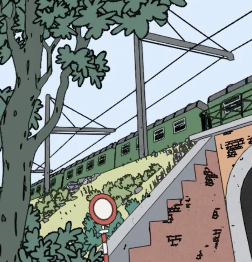
🖍️ A tutorial on how to render outlines as a post-processing effect in Unity 6 and Unity 2022. Makes use of an edge-detection technique based on depth, normals and colors, and can be used in Unity's Universal Render Pipeline (URP) using the new Render Graph API. Can be used for game mechanics or stylistic rendering.
ShaderPassName is just an enum in my code, you just pass it a string that will be shown in the frame debuffer
Oh right, right as I sent that message it clicked. Sorry!
Is InitSectionRendererList also a method you wrote?
Sure this is the code of recordrendergraph
And yeah there are several custom methods, if your IDE doesn't recognize it, it's probably mine.
That InitSectionRendererList does this (with some parts left out)
var drawingSettings = RenderingUtils.CreateDrawingSettings(RenderUtils.DefaultShaderTagIds, universalRenderingData, cameraData, lightData, sortingCriteria);

                var filteringSettings = new FilteringSettings(renderQueueRange, -1, settings.SectionRenderingLayer);

drawingSettings.overrideMaterial = section;

renderGraph.CreateRendererList(param);
I don't really want to share the full code but this should give the idea. To render to the section map, you set filteringsettings (here I filter using rendering layers), then I set an overridematerial so each object will render using that override material to the section map. This overridematerial for example is a simple material that outputs vertex color, or a random ID based on world position.
Look at the RenderObjectsPass from Unity, they do the same thing and there you can see the full code.
Right, that makes sense. Thank you. Ill see if theres more material on how to do a section render online
The RenderObjectsPass really should give a good idea on how to render only some objects. By then using builder.SetRenderAttachment(sectionHandle, 0); you tell Unity to render to a custom handle. Combine that with the edge detection pass, and you then are able to use the section map as input.
Okay, thanks for the help!
Hey, sorry to bother you but Im not sure how the Render texture in your tutorial is passed to the shader. I dont see any reference to it in the shader either
Yeah so the handle is made like this
 // Section buffer.
  var sectionBufferDescriptor = cameraData.cameraTargetDescriptor;
  sectionBufferDescriptor.graphicsFormat = GraphicsFormat.R16_UNorm;
  sectionBufferDescriptor.depthBufferBits = (int) DepthBits.None;
  sectionBufferDescriptor.msaaSamples = 1;
  sectionHandle = UniversalRenderer.CreateRenderGraphTexture(renderGraph, sectionBufferDescriptor, Buffer.Section, false);
And then I sample it like this in the shader. So
SAMPLE_TEXTURE2D_X(_CameraSectioningTexture, sampler_CameraSectioningTexture, UnityStereoTransformScreenSpaceTex(uv));
and so in the rendering code I did
builder.SetGlobalTextureAfterPass(sectionHandle, ShaderPropertyId.CameraSectioningTexture);
Where ShaderPropertyId.CameraSectioningTexture = Shader.PropertyToID("_CameraSectioningTexture");
Thanks for the clear explanation!
In the shader the name _CameraSectioningTexture isnt recognized, do I just have to define it as a property in the pass?
Check the DeclareOpaqueTexture.hlsl file from Unity, I do it the same way for mine
Yoo, ive never thought that ill find you like that.
Tho i have a question, how can i create a waterline effect

This like underwater rendering
Also what abt water interaction?
Hello,
I’ve been facing an issue for the past two days with shader programming. I’m new to it, so I’ve been using Shader Graph because it’s easier to grasp. I’m using it to color custom meshes for my procedurally generated terrain.
I recently found a shader online to create grass, and I want the grass to take on the color of the terrain mesh underneath it. However, I can’t figure out how to pass the terrain shader’s color information to the grass shader. I’m not even sure if this is possible.
I tried generating the shader code from my Shader Graph, but the file is over 7,000 lines long, and I couldn’t identify a specific function that my grass shader could call to retrieve the terrain color.
I’d appreciate any suggestions on how to solve this, thank you
So are you using unity's built-in terrain?
Terrain uses "splat maps" or "alpha maps" to store each terrain layer's weight for each terrain pixel
Maybe you can get that from the terrain material somehow and pass it into the shader
Sounds pretty complex tho
Especially if you have multiple terrains
It’s definitely possible to pass color information from one shader to another, though it requires some extra setup since shaders don’t communicate directly. Here the things you can do:
- Bake the Terrain Colors to a Texture
You can render the terrain mesh’s colors to a texture.
Pass this texture to the grass shader as a property.
Use the world position of the grass vertices to sample the corresponding color from the texture.
Or you can set a layer to terrain then use a top-down camera and use that layer to cull otherthings and just render the terrain.
Then use the camera output to a render texture. Then use the texture on the grass using world space uv.
That way it will update the grass color in realtime
I'd want to bake it into one texture, yeah
I'm not sure how I'd handle that
Ideally you'd make a shader that does that, rather than manually reading every pixel from every layer's texture in a script
probably a pretty common question. but, am i better off learning HLSL, and manually coding shaders, or should i learn shadergraph? i primarily use URP
im pretty new to shaders but i think i understand the basics
Shadergraph first to understand some general shader concepts
Imo
Shader graph can be used pretty far without knowing any of the basics, so it's not that useful for learning
But it gives you nice results much quicker and works with URP
It's harder and less practical to write shaders manually for URP so it's not a great environment for learning that
So if you want to make shaders SG is great
But if you want to really comprehend them too it's best to practice writing them for a BiRP project and study the topic on its own
good to know. i haven't used the BiRP in a while. if i ever do then i'll try learning some more HLSL 
Hi, I'm making a water shader in URP and I'm having trouble with creating a depth fade. I'm following along with a YouTube video in which the guy creates this subshader to make the shore fade from dark (deep water) to light (shallow water). It works pretty well but it seems to be based on like the camera/eye perspective and not just the depth of the water (or the distance of the object below the ocean plane that I have). Therefore objects that are closer (not necessarily in shallower water) appear brighter. Would anyone know how to make it based on the depth of the object below the water plane and not the camera depth? Thanks!


Instead of the Raw Screen Position A, try Position node (View space) -> Split B -> Absolute (-> replacing B port on the Subtract)
That worked! Thanks!!!
Okay thanks a lot, I will try the baking, I saw the render texture trick online, but I don't think it could work in my case, since my map is procedural and can get very large
What does this mean? 😅
Hello! I am trying to create refraction effect for water and glass, but there is an issue: shader refracts the whole scene color, which causes objects in front of the glass appear refracted too, you can clearly see it by bits of color of the object around it. It becomes a real problem when it comes to refracting transparent stuff, but the biggest question is how it is done in source engine from 2004 and is there a way to replicate this in unity? You can clearly see that source engine just ignores and don't refract anything in front of the water, which is not the case in my shader (graph is attached, it has some simple math tricks, but nothing to complicated). I am using last verison of URP in Unity 6 lastest version, if that helps.


I have some info about that here under refraction ‘going the extra mile’.
Not saying it’s the best method, but it worked for me.
okay, I will take a look, thank you!
what causes these insane visual artifacts when setting the alpha channel to extremely high values like -1e+15 or 1e+15?
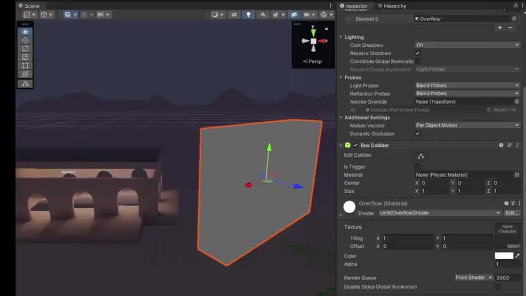
fragment shader is:
       fixed4 frag (v2f i) : SV_Target
            {
                fixed4 col = _Color;
                col.a = _Alpha;
                return col;
            }
Just curious what goes on under the hood in the GPU that causes a random orange outline to be drawn when the alpha channel is -1e+15?
To answer that we'll need to know how the render target is used later in the frame rendering.
Do you have any post processing effects enabled?
The gpu on it's own doesn't do anything special. It just executes the shaders that you bind to it. So the origin of these issues must be in one of the shaders as well.
I know you since 2021 when i was kid trying to make games. And i saw you
Assuming your shader actually represents the final result, one possible explanation is different precision of floating point variables in the inspector and the shader itself. If it's 32 bit in the inspector, but 16 bit in the shader, extreme values might be represented differently.
Generally alpha is supposed to be in the 0-1 range.
Though the color going out of the mesh pixels is probably due to some pp effect. Blue, bloom, down sampling. Something like that.
likely bloom
how do you go about making all your custom shaders compatable with unity's built in features for shadows and global illumination etc... do you have to do it all manually?
and also does anyone know if / where I can find unity's code for some of their built in shaders like URP/lit (ok you just have to click the three dots button and click edit shader)
do you guys ever just add onto premade unity shaders directly?
Generally easiest if you start with a shader graph
what if you dont want with all of unity's lit functionality though? Like it seems like they automatically apply their pbr models when you choose a lit shader graph, and Im not sure if you can overwrite that?
You can look at the code it generates and strip that back. Or start from the source code that's shipped in the packages
ok yeah, thats kinda what I was thinking too. Thanks
almost two years into gamedev and still so much to learn, especially rendering
I'd advise against starting with Shader Graph code cause it'd be full of garbage randomly generated variable names and shader graph specific defines. Reading the Lit shader's source code in the PackageCache in your Library is way easier.
hi guys, is there a way to create an effect like this with scaling the texture?
so i want to make voronoi texture density based on another texture like GradientNoise to create this kind of effect. But when i plug the noise to density, it just gets distored. I guess its because the texture is scaling from uv center and not just making the dots more dense at darker points. Do you have any ideas how to create this effect in some other way?

The image is just the thing i want to achieve, the left is voronoi reffrence, and the right is the texutre that density should be based on
Oh i just noticed i could just lerp between 2 diffrently scaled voronoi textures based on noise
or blend idk how it called in shaders
ah nevermind it kinda looks bad
but its okay i guess
I'm trying to convert a blender material to a unity shader graph and i'm stuck on finding an equivalent to invert color node. Invert, Flip and Negate all just make the end result pure black. Here's the blender before and after and unitys before and after.
Not ideal.
I should mention that invert colors doesn't visually do anything until ticking the red checkbox after which it just gets tinted slightly darker.


pls help, my shaders broke and not compiling, idk whats the issue

I don't know which "the red checkbox" you mean but One Minus node does the same as inverting colors
the invert color node has a checkbox for the red channel, thats the one i meant. It looks like the one minus node does the trick though!
You can swizzle or split to get a specific channel
One minus flips values in 0-1 range but if your source color is not in that range the result might be unexpected
How can anyone help you if you give 0 information? Is there a compile error for the shader? Is the shader for a different render pipeline than you are using?
no
i idk about pipeline, but no compiler errors
You probably did something at the time that they broke
is it a lit shader, unlit? If it was made for say the built in rendering system but you are using URP/HDRP in the project, it wont work and will remain pink.
There's just no clues for us at all
idk random cubemap shader...
sorry

i didnt noticed that
aha that is something. unless this shader does something special just use unitys included cubemap/sky shaders
how do i texture them
i need this for a mirror
ok if be honest i just decompiled them from a random game using assetripper
nah it just dissapeard
i tried surface vanished

i wont help with some rando ripped shader
maybe you know how to rip shaders right?..
maybe...
assets ripping and decompiling are prohibited topics in this community.
having some trouble with the main light direction node. For some reason it just doesn't work? This is the setup its used in, when the main light direction is plugged in the end product isn't visible because its multiplied with black. When using the float to simulate a fake light direction the shader does give back something visible. Since the light and object the shader is on don't move i could technically predefine the light angle with the float but i'd like to reuse this for other projects maybe

iirc the node functions in URP and HDRP (maybe), but not in Built-in RP
ah i'll have to check which pipeline i'm using then. Not sure currently
yup, looks like i'm using built-in. How do i change that?
ah found it
ah. Looks like vrchat only supports the built in pipeline for some reason
Does anyone know which shader graph works for ui images, or there isn't one for ui
I don't think it works at all, times I tried failed. Dl the official unity shader sources and modify the UI ones there
There is a Canvas Graph in 2023.2+
For older versions the unlit kinda works, but only on a Screenspace-Camera type canvas, not overlay. More info here : https://www.cyanilux.com/faq/#sg-ui
Okay thanks
Yo there is?? Im stuck on 2022 so guess thats why I didnt know 😭 (we are slow at moving our projects to newer versions)
I too have 2022, but I'm not gonna update it now, at least for a while
It does work but keeps on saying there's no _Stencil property in the material ;/
I'll just leave it as it is maybe.
all ui shaders need stencil support for masking
the transparent shader is set to:
Blend SrcAlpha OneMinusSrcAlpha
BlendOp Add
So it's expected that for alpha > 1, the color of the geometry behind it gets inverted. But why does it only work for emissive color? Not albedo?