#archived-shaders
1 messages · Page 88 of 1
This is urp so I expect a lot of stupid problems that aren't very well documented
RenderType = bacgkround helped
iirc it either needs a specific tag or the name needs to contain Skybox for the warning to be removed
Yeah I pried apart a bunch of shader and looks like it's just render type thing
Man, anyone used Amplify around here? I noticed I had it purchased and gave it a try but can't get it to render skyboxes in urp
And in built-in shader graph it just works. Are there some tags you need to enable?
For debugging purposed it should be red, but only 1 side of it is, and everything else has broken depth

Ah, it's that light mode thing
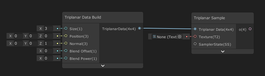
In Shadergraph, there should probably be a way to describe the 'type' of an input in a subgraph, so that by default Unity displays the dropdown choice for the subgraph node. A lot of my subgraphs are 'visually useless' because I use an input parameter. I don't know how to explain this but compare the top to the bottom of this example

You can use the Branch On Input Connection node to override the previews. It also means the subgraph will default to a different value (UV0 here) when nothing is connected to the port
(It can't provide a dropdown for other channels like the one on the Rotate node though - but a user can still choose to override it by connecting a UV node of course)

Note that feature requires Unity 2021.2+
Wow, thanks a lot for this. I can't believe I never knew about this node. This is exactly what I needed
Hey all! I'm currently trying to use a HLSL shader / .shader material to blit a "Gaussian Blur" effect onto a Render Texture however, no matter what shader I try (even basic ones), the material in the preview seems to be outputting correctly, when I check the frame debugger it will always output a full black screen, if anyone knows what may be going on any help would be amazing! I've been trying to look into this now for a couple days and can't seem to find anything explaining why this may be occuring, I'll attach a screenshot of the material in the preview and the outputted render texture, along with the scriptable renderer feature pass in a thread below!
Thanks all!
Any idea why the rain (VFX particle lines) disappear at this specific angle/distance? They still exist + the splashes still appear on collision, the initial rain just can't be seen. If I disable the sea plane the problem is solved, so I suspect it has something to do with the water shader. (In fact, you can see the rain that is appearing on top of the boat, only the rain that is "masked" by the sea is invisible)
Maybe it's a sorting issue. In that problematic angle try to make the origin of the effect closer to camera
Or give water lesser priority
ooo that did it. thanks. 🤦
Hi, I have this shader i got from a tutorial on how to make a portal, and im trying to use it for a vr game, but whenever I try testing it, it only shows on the left eye, and the right eye just doesnt render the portal and renders everything else, i think this is the shader because everything else is set correctly, can anyone help?
Shader "Unlit/Portal"
{
Properties
{
_MainTex ("Texture", 2D) = "white" {}
}
SubShader
{
Tags { "RenderType"="Opaque" }
LOD 100
    Pass
    {
        CGPROGRAM
        #pragma vertex vert
        #pragma fragment frag
        // make fog work
        #pragma multi_compile_fog

        #include "UnityCG.cginc"

        struct appdata
        {
            float4 vertex : POSITION;
            float2 uv : TEXCOORD0;
        };

        struct v2f
        {
            float4 uv : TEXCOORD0;
            float4 vertex : SV_POSITION;
        };

        sampler2D _MainTex;
        float4 _MainTex_ST;

        v2f vert (appdata v)
        {
            v2f o;
            o.vertex = UnityObjectToClipPos(v.vertex);
            o.uv = ComputeScreenPos(o.vertex);
            return o;
        }

        fixed4 frag (v2f i) : SV_Target
        {
            fixed4 col = tex2D(_MainTex, i.uv.xy / i.uv.w);
            return col;
        }
        ENDCG
    }
}
}
You have to setup the shader for stereo: https://docs.unity3d.com/Manual/SinglePassInstancing.html

What would be an approach to creating star-like shapes similar to those? (the ones that go ✨ )

Simple to do with a texture, but I was wondering whether it can be done procedurally
One of those things that seem simple from visual standpoint but borderline impossible in shader programming. I think you really can only use a texture for this
Draw a quad, and use a formula like 1/x to get star border. Every point with coordinates less then border value will get fill. Multiply by distance to the center to get smooth fade.
Yeah, that's for drawing individual stars

Yea
The issue is placing them on a plane, multiple instances of
I already learned that shaders aren't the best fit for that
Make a graphics buffer with per-star data. Position and scale
Use Graphics.DrawProcedural to draw all stars in one call
Use vertex shader to expand each star mesh (2 triangles) using per-instance scale data + position offset
Yeah, a hybrid solution will work
I don't think it's possible with just shader, without any other draw commands
You can kinda fake the round stars with noise pow, but this is far too complex
You can also make a star shape blur of your star picture.

Star fields were some of the first effect I ever coded, back in the late 80's. I decided to revisit this effect and make a 2020 shader version of it. In this video we'll be making this effect in SHaderToy, from scratch!
Twitter: @The_ArtOfCode
Facebook: https://www.facebook.com/groups/theartofcode/
Patreon: https://www.patreon.com/TheArtOfCode
...
Alright this looks very promising, ty
Wow stars aside this guys explains some of the concepts of shader math really well
Hello, i was thinking that perhaps here i could find help.
I'm making buttons for my game and i have decorations that change colors over time by shifting their hue, and i wanted to create my button so that it changes color too. Now, i hae no idea how to do this. Shader doesn't work (at least the one i wrote) and what my first idea was a colormap. Idk if that's a known global term, but: R value is how much of texture 1, G is how much of texture 2... and with that the texture is now basically a variable, and combining the multiples i get a texture that can change. My main issue is combining this with 9-slice, cuz it's a button.
My general idea was:
- default: global1 for border, white for center
- hover: global2 for border, white for center
- active: global2 for border, global1 for center
global1 is HSV(Time, 100%, 60%), global2 is HSV(Time + 180°, 100%, 60%)
If i should seek help in another chanel, tell me, i have no idea how to solve this.

This guy is the king, you should totally watch his other videos about writing shaders. Series about raymarching blew my mind (and gave pretty neat explanation about SDFs)
No joke I learned an insane amount of info from this tutorial alone and better understand how rendering works now
And it was like, casual
He's just making an effect and dropping useful info in the meantime
The best thing about them is that he claims he's not a mathematician, so gives "visual" explanations about shader math with desmos n stuff
Math is highly visual tbh
Shaders ARE almost pure math if you think about it
I think there's a misconception that visualizations exist to make math easier to understand when it's really just how it works
Yes, but many tutorials are just formulas shown on blackboard with some mathematical gibberish that I don't understand so well as artofcode
It's a conspiracy by mathematicians to make math harder to understand and make them look smarter fr
But jokes aside this dude rocks
Totally xd
Also while we're here, is manually doing aspect ratio calculations in order to prevent checkerboard from stretching in screen space the only way of doing that?

Or is there a node for this I missed?
Yes, you need to take aspect into account
Hey guys, I'm testing out some shaders on sprites and I've run into a problem: Using sprite sheets causes the shader to be applied to the whole texture instead of treating the sliced sprite as its own texture, any workaround for that?
(on the left is a sprite part of a 5x5 sprite sheet and on the right is a sprite not part of a sprite sheet)

Is it even possible to create a simple black outline shader for hard surface and soft surface objects at once?
Like I feel like this is harder than it should be lmao
this is inside of blender,
Would making screen space outlines be easier or should I make an actual shader to achieve this?

Found a solution

I feel like I need to understand the root of the issue instead of ignoring it and randomly tweaking stuff until it disappears
Why does this happen?

This is a custom skybox. Sometimes it would just do that (not draw anything at all over previous frame)
It's similar to when you put "unitialized" as your camera background type. Here, all I did was remove SV_POSITION and add UNITY_VPOS_TYPE screenPos : VPOS to try and use screen space
Also I'm not super familiar with shader performance and how much GPU time matters. Is this normal performance for a skybox shader? (left is on, right is off)

Nonsensically it performs better than empty no material skybox in a standalone build, in terms of GPU load (left is with skybox material, right is without skybox material)

No idea what's wrong lol
That doesn't seem very reliable measure of performance. What are you trying to find out and why? Did you make your own skybox shader or something?
Yeah its a custom skybox. I was trying to see how well it performs but profiling shaders is such a pain
I'm reading up that nvidia profiler thing rn
NSight or whatever
Thank you for the shader graph, again. I implemented it and played around with it a bit. Even though I can get the shader to work I feel like I don't fully understand the parameters. I would expect to just feed in the length of the line and the percentage of where the texture is being cut. Can you help me understand the parameters better? 🙂
I think I did some more changes afterward, so in doubt, here is the version I have currently.
For the 9 slices to work, you need a minimum of 2 vec4 inputs indeed, where in the texture the slices are, and where in the "output" to place them.
But I found that it's not obvious at all to place those values, so I decided to use pixel numbers instead.
- The "reference size" is the size of the texture used for slicing.
- The "display size" is the actual size of the final "sprite", it should be bigger than the reference size.
- The "borders" is the slices (left, right bottom top) sizes of the texture.
It's easier to input that you want a texture of 32x32px to be "scaled" to 100x100px with borders that are 10px width than to set the precise UV values in floating points.
-
The "uv" input is your reference UV. It uses UV0 by default, but you can override it.
-
You can set the center and borders tiling mode with the dropdowns.
-
The "uv" output, is the sliced UVs, use this to sample the texture.
-
The "ddx" and "ddy" outputs are to use with a SampleGrad function, to avoir mip map glitches in cases if your sprite texture has mip maps (see the custom function screenshot)


Thank you so much!
(I'd also appreciate any info on how to reliably profile it)
Oh no, I'm hitting floating precision issues and they aren't looking simple to solve
Tried adapting acerola's compute shader for ortho camera + my project's grass data structs, but the culling is ridiculously aggressive. Shader people, is there anything egregiously wrong with how I'm sampling the camera as to cause everything to be culled?
relevant snippets, since I imagine this is an issue with vote.
InstancesBehavior.cs
cullingComputeShader.SetMatrix("MATRIX_VP", cullingCamera.projectionMatrix * cullingCamera.transform.worldToLocalMatrix);
cullingComputeShader.SetVector("_CameraPosition", cullingCamera.transform.position);
cullingComputeShader.SetFloat("_Distance", 200f);
cullingComputeShader.SetFloat("_OrthographicSize", cullingCamera.orthographicSize);
cullingComputeShader.SetFloat("_AspectRatio", cullingCamera.aspect);

cullingComputeShader.SetBuffer(0, "_GrassDataBuffer", info.dataBuffer);
cullingComputeShader.SetBuffer(0, "_VoteBuffer", voteBuffer);
cullingComputeShader.Dispatch(0, Mathf.CeilToInt(info.dataBuffer.count / 128f), 1, 1);
Culling.compute
[numthreads(128, 1, 1)]
void Vote(uint3 id : SV_DispatchThreadID) {
    float4 position = float4(_GrassDataBuffer[id.x].TRS._m03_m13_m23, 1.0f);

    float4 viewspace = mul(MATRIX_VP, position);

    bool inView;
    bool withinDistance;

    float2 viewport = float2(_OrthographicSize * _AspectRatio, _OrthographicSize);
    float2 viewportMin = _CameraPosition.xy - viewport;
    float2 viewportMax = _CameraPosition.xy + viewport;

    inView = all(position.xy >= viewportMin && position.xy <= viewportMax) && viewspace.z > 0;
    withinDistance = abs(viewspace.z) < _Distance;

    _VoteBuffer[id.x] = inView * withinDistance; // If I set this to 1, all grass is rendered
}
I'm trying to figure out how to plug a triplanar heightmap into tessellation displacement
I see tutorials for UV
but I can't even plug the triplanar nodes into the same stuff
im trying to make a very simple pixelated look kind of starfield shader
anyone know why im getting this flickering

i tried adding a contrast node thinking it ws just because certain stars might be so dim its causing it to flicker. But im not sure if thats the case
there is basically just a quad background with this shader on it with the camera as the parent so when the camera moves the quad moves, with the position node in the shader causing the offset to look like the whol ebackground is moving
Hey all, I need to "assemble" a texure from particles, I want particles flying in from one side and then locking into place to build up a texture. The texture is not big (about 100x700 pixels). Needs to run under URP
Is this possible with a shader? How would I go about doing this, roughly
how do I use fog with unlit materials?
It's all makes total sense. When you use a skybox, it needs to render more, and thus uses more GPU resources and taking more time. It would be nonsensical if it was the other way around.
Might be easier to do with a vfx graph
Does anyone happen to know the requirements of the "renderingData.cullResults" if I am drawing it to a target in a scriptable renderer pass? Currently trying to draw a tilemap to a RTHandle however it only seems to draw when the tilemap has a "Sprite-Lit-Default" I assume that means my "drawingSettings" are only masking "Lit" materials but I'm just wondering if there's a way to change that?
The reason I need it to be "Unlit" preferably is so my scene lights do not affect my tilemap, but still draw the tilemap to a texture which I can then use as a mask to add custom lighting to using the scene lights. If anyone has any idea what tags I might be able to add to get that to happen I would be very appreciative, thanks all :D
Found this tag which worked!
shaderTagsList.Add(new ShaderTagId("SRPDefaultUnlit"));
Does anybody know how I might be able to sample the color of a pixel of the HDRP physically based sky ?
Do you actually read the messages or just reply to the images
You said (left is with skybox material, right is without skybox material) and left is on, right is off.
I see now that the second screenshot has an increase in 3D measure, which I didn't notice earlier. However, it's not clear what that metric expresses. And there is no such contradiction in the profiler data on the first screenshot.
Yeah that's what's nonsensical
Why is my gpu being utilized more in a standalone build with no skybox?
I'm pretty sure that's just a gpu utilization graph
is Shader Graph is good for vegetation rendering in mobile?
For example, it could be updating faster due to lack of the draw call making it use more resources in the short amount of time. On the other hand, that draw call could be very inefficient using only small portion of the GPU resources, thus reducing the average GPU usage.
It's really hard to say without understanding what metric that is and how it's calculated
Shadergraph is a tool to make shaders, if the said shader works nicely on mobile or not depends on what you put in there.
what about overdraw?
The answer still applies, overdraw is caused by having multiple things rendering into the same pixel, it is not directly related to the tool itself.
Got it.
So is there any way to reduce overdraw?
- Use LODs to avoid have sub pixel triangles
- Use opaque materials instead of transparent as much as possible (ie. alpha cut instead of transparent for leaves)
- But avoid large area of transparent pixels that are cut off by "cutting" around the shape with the mesh
Thanks for sharing the points.
I am following first two points as you have mentioned.
Large area of transparent( Forest) I have created for game. Here I am facing overdraw issue.
Here I was speaking of the mesh itself. IE, if you use a single quad for a leaf with alpha cut, a lot of pixel end up beeing sampled to just be discarded. If possible, modify the mesh to have a tighter fit around the visible shape.
A depth prepass might also help with overdraw.
Thanks @amber saffron .
I will try it.
I am trying to set up a double-sided material on this curtain mesh, however when I use the universal render pipeline/lit shader and set render face to both, my material color is completely different on the backside. I also tried using the Ciconia Studio double-sided shaders, but they just turn my object fully pink. I also tried selecting the material and clicking on 'Convert selected Built-in materials to URP', but this also did nothing. Does anyone know why this is happening?


The weird lighting happens because two-sidedness doesn't flip the normal, so the lighting is inverted in a sense
The pinkness isn't fixed by converting because the material converter can't do anything with custom shaders, all it does is look for Unity's default BiRP shaders and swap them for URP counterparts
Thank you for the explanation! Do you know how I can set up a proper double sided material in my scene? Since none of the custom shaders work for me.
You will have to create a shadergraph for you object, set to double side, and manually flip the normal (using the "Is Front Face" nodes).
Another solution to avoid having to maintain extra shaders is to keep it one-sided and simply duplicate and flip the faces of the mesh itself in a modeling program
Yes true, but I was trying to avoid that, since the mesh is already quite high poly and that would double the polycount.
But I am not sure how expensive this double-sided shader would be.
GPUs are good at rendering lots of polygons, and URP can handle different shaders well
So both are good options really
Because URP uses SRP Batcher, there is also an overhead of having multiple different shaders in your scene so if that's the only object that would need the shader, it might actually be faster to just do douple sided mesh and use a standard shader even though it makes the polycount higher. That should mostly affect the memory consuption because the pixel shader won't even run for a triangles pointing away from the camera.
So does nobody know how to plug a triplanar heightmap into tessellation displacement in shader graph?
0 information exists online
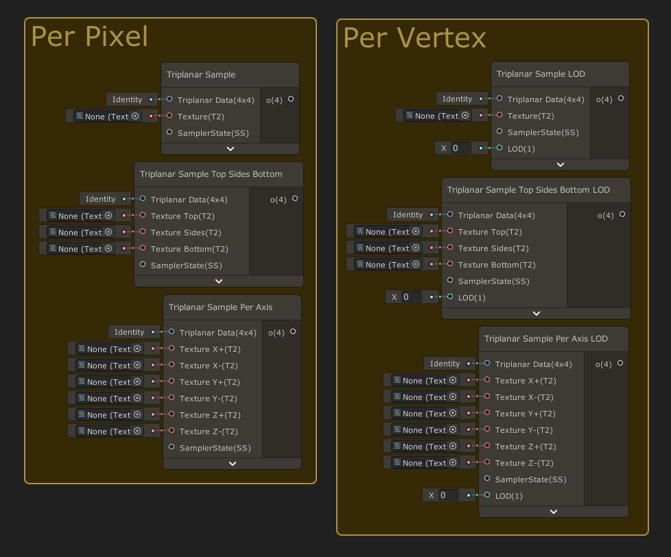
You'll need to build your own triplanar node (subgraph), and to use SampleTexture2DLOD, as the built in triplanar can only be used in the fragment shader.
If you want, you can use the ones I have here : https://github.com/Remy-Maetz/sg-node-library
(Usage : https://github.com/Remy-Maetz/sg-node-library/blob/master/Documentation~/images/nodes/triplanar/sample.png?raw=true & https://github.com/Remy-Maetz/sg-node-library/blob/master/Documentation~/images/nodes/triplanar/samples.png?raw=true)
GitHub
Node library for ShaderGraph. Contribute to Remy-Maetz/sg-node-library development by creating an account on GitHub.
Woah I don't really understand this
I will try to make it on my own because I actually want to learn
But I will use my own if I don't figure it out
I am blending it per vertex color...that is doable with lerp, yea?
Yes
Keep in mind that blending triplanar multiplies the number of texture samples, and can end up beeing costly.
I have 4 right now and I will use the 5th one
That fine?
Should still be better than just a texture blend, right?
Vertex color is the fastest, should be
I'm not sure to understand.
What I'm saying, is that if you use vertex color to blend the result of triplanar nodes, which are texture samples, you can end up having 12 (4 color channel x 3 samples per triplanar) samples per pixel/vertex.
I understand, I understand
But where do you plug these? I guess I'll just download yours and see
In a HDRP Lit shadergraph with tesselation, you can use them with the position vertex input. Bu you have to do the displacement calculation yourself (usually, position + normal * heightmap * amplitude)
hi im trying to get grahpics or textures similar to that of lethal company - heads up i dont have a lot of time and i know nothing about unity
Hi I'm trying to get million dollars similar to how Elon Musk has. I don't have a lot of time and I don't know anything about making money
In Unity 6, when exactly is RecordRenderGraph called?
I have a list of renderers where I need to access each renderer's texture in the ExecutePass callback function. Do I have to create and maintain another list of TextureHandle's? If so, where do I do that? In RecordRenderGraph?
First time Shader Graph user... thought I finally had what I needed figured out.. but..
Why is this happening? I cant understand.. Why can't I use this value to modify the transform and also output to Vertex Position?
Replace the "Sample Texture 2D" node with "Sample Texture 2D LOD"
To put is short, the first one can only be used in the fragment context.
Thank you!
Hello! So I am currently in the process of creating a landscape material and I have this color gradient that I sample depending on the current y position(divided by maxHeight to get range from 0-1) and it works fine. The problem is when I want to have multiple different terrains which all have their own "max heights". Now I do know that there are material variants but creating a variant for every single terrain tile and set the max height doesnt seem practical. So my question is. Is there a way to get the y position between 0-1 without knowing/setting a maximum height? I do know there are heightmap textures I can use, but that doesnt resolve my problem. I would still have to create a material variant for every terrain tile.


You should be able to use the bounds output of the object node to get the height of the object.
When I split the bounds size and use the G value instead of the height parameter I get this weird effect

Well, if you remap the gradient over the local min and max of all the tiles, obviously, you end up having seams (logic).
Having a single material with an exposed setting where you send the overall min and max height of all the terrain tiles makes it so that the gradient is consistant between all tiles. Like you had originally ? 😅
hmmm ye I guess your right, thanks anyways!
Between all of these ones, which ones do I need? Is it only the triplanar sample LOD one? Because it behaves like the sample texture lod?
and therefore everything important is inside it
I would test with that but I am getting the validation error, can't find GUID
Oh ? ... I didn't upgrade my node library for a while, maybe it has some issue when beeing imported to recent versions ....
Hum, I've imported it into a project using Unity 2022.3.46, and don't have any GUID error, could you give more details ?
But indeed, for you need you use "Triplanar Sample LOD". Unless you want to have different textures per faces, than you have the other variants 🙂
Hi, how can I make the position of the cube affect the entire height of the character?


To my understanding, the cube here serves as the target for the "position" input of the character shader, and draws a sphere mask, right ?
Apparently, simply increasing the "distance" value should do the job ?
Or did I misunderstand something ?
I'll try to explain better even though I don't understand much about shader graph.
Position is the position of the cube (the shader is on the character)
Distance is "How far away should the cube be to affect the character"
Right now the distance I have is correct but I want it to affect the entire Y axis of the character
That the height of the cube does not affect the dissolving effect
So, only dissolve based on the horizontal coordinates ?
yes
That or use the full width and height of the object
Then you simply have to insert swizzle nodes with "XZ" in text field, between the two positions and the "distance" node.
I want the effect to occur when approaching a door
like that?

Nah, at those spots :

Out of curiosity I want it to affect the dimensions of the cube, would it be much more difficult?
You'll need to calculate the mask differently, and pass the dimension of the cube.
Subtract the "current" position and the cube position, to the position relative to the cube center.
Divide that value by the cube dimensions.
Take the absolute of that, and combine the X, Y and Z value to have a 3D mask
The combining part is up to you to decide what "shape" the mask will have, you could simply multiply the values together to have some sort of "stretched sphere" shape.
Like that?
position is "gameobject.transform.position" and bounds are the dimensions of the collider

Nah, subtract only once, the cube position from the "absolute world position"
that's the result then, and I connect this with the node of dividing by the distance, right?

Sub Graph at Assets/Triplanar Sample LOD.shadersubgraph has 1 error(s), the first is: Validation: Could not find Sub Graph asset with GUID 048360b269ad6df429d1e454f921c21d.
(Filename: .\Library\PackageCache\com.unity.shadergraph\Editor\Importers\ShaderGraphImporter.cs Line: 395)
I'm using unity 6 preview if that means anything
Can someone recommend a good and up-to-date tutorial for VFX Graph?
Hey everyone, I'm trying to make a shader for a segmented health bar. Currently I'm using this set up but I'm not happy with it because of the segment space right at the start of the bar and the lack of control over the segment spaces width
Anyone know a better set up?

Have you gone through the samples available with the VFX package? Those demos cover so much territory. Then on top of that they have more advanced examples here. https://github.com/Unity-Technologies/VisualEffectGraph-Samples

GitHub
Visual Effect Graph - Samples Project. Contribute to Unity-Technologies/VisualEffectGraph-Samples development by creating an account on GitHub.
In URP is there a node/simple way to get the grabpass / pixels behind a transparent mesh? I'm using Scene Node atm, but it's not great. Is it possible to get it by using the custom function?
What exactly are you trying to get? The scene color before the object is rendered? If so, what's the problem with the scene(color?) node?
Maybe i'm doing it wrong. But I'm creating a transparent distortion shader that distortions what's behind it for various purposes, like explosions, etc. It looks cool (with scene color node), but sometimes it distorts things in front of it (like the player character or his arms if you're too close)
Are you using a deferred renderer?
Basically, if it distorts things in front of it, it means that they are rendered before the transparent object and so are included in the scene color.
A forward renderer would usually render opaque geometry first and then transparent, regardless of what's in front of what, iirc.
using Forward+ atm
A deferred renderer would render the depth maps first, so when the actual object is rendered, it would clip whatever is hidden behind other objects.
Found something that works, but need to convert it to unity 6: https://github.com/lukakldiashvili/URP-Transparent-Distortion-Example
Seems like you need to create a render feature.
GitHub
Example Unity URP project, demonstrating distortion(heatwave) effect on opaque and transparent objects - GitHub - lukakldiashvili/URP-Transparent-Distortion-Example: Example Unity URP project, dem...
You could probably just check the depth buffer in your shader and discard pixels that fail the check.
I don't know what is the use of it?
Anyone have any idea what is the use of this node and where its recommended? Will put any impact on output?

This is for calculating and sampling a specific mip map level afaik. The regular sampling node does that automatically behind the scenes, so you wouldn't need to use these nodes normally.
Thanks @kind juniper 😀
I've just tested with Unity 6.0.20f1, and it works without issue 🤔
Did you maybe not import the whole package ?
This node includes an other subgraph of the library to work.
Hey guys, I'm trying to conseptualise a certain shader feature. It's a shiled vfx shader. Now my idea is to have a buffer of a fixed size with the positions for the hit sphere masks that is being written to from c# based on the collision hits. I also want the hits to smoothly fade however. Would writing emission values to a seperate buffer every frame from c# be a good idea or is there a better way to do it in the shader? Maybe another option is to dispatch a compute shader to write the emission values everytime we get a new hit or something.
Does it need to be a buffer ? You could get away with a VectorArray (float4 hits[]), where xyz is the position, and w the emission intensity. Just update it from script and use Material.SetVectorArray to send it to the shader.
Else, indeed using a compute to handle the buffer update, and to avoid writing to the buffer from cpu, the compute could also have some input variable to add new hits to the buffer.
Ah yes, I imported the whole thing and now it works
do you happen to know what exactly I need to import, just to avoid my project being messy (this is my test project now). If not, doesn't matter, it isn't a lot memory
one last thing, when I mentioned vertex shaders, you mentioned 4 textures blending. Can't I easily use 5 due to the fact I'm blending 2 new textures on the first lerp?
I didn't re-check all the dependencies, but maybe just the Triplanar folder would be enough.
Else, the Runtime folder is the one that contains only the nodes logic.
Finally, if you don't want to bload your project folder, you could just import the full repository with package manager, so it won't show up in the Assets.
I have no idea of what you are doing in your vertex shader currently, I was just wild guessing that you wanted to use the 4 channels of the vertex color to blend 4 textures.
I am building upon the sample hdrp shader for polybrush, which is garbage
but what it had was texture 1 and texture 2 lerp on the G channel of vertex color
then result of that lerp lerps with texture 3 on B channel
and result of that lerp lerps with texture 4 on A channel
that's 4 textures and R is unused
there's nothing wrong with that right? 5 is the max I can do with vertex color to my knowledge
No, nothing wrong
After some optimizations I'm down to 0.7ms drop from the previous 5.5ms (VSync off) 😈
I'm assuming everything under 1ms is fine? For lower end devices
The shader is for a skybox, so it will be visible 99% of the time
Hey folks, trying to figure out the best method, inherited code and trying to reduce the slowness of it.
Its generating a scene which is being sent over network. The setup right now uses 6 cameras side by side, each renders to a texture, then each texture gets sent as a frame. It seems to me, and correct me if I'm wrong here, but it would probably be much more efficient to use a single, much larger camera, write that to a texture, then blit a section of that texture to 6 temp render textures, and send each. Seems like multiple cameras and multiple textures would have way more overhead. Sound about accurate?
What's bottlenecking it, the networking part of it or the rendering to texture part?
Definitely the rendering
There are other bits I'm going to dig into later with some of the other scripts, but a big chunk (20-30ms) is purely waiting on the renders. Trimming down the quantity of cameras (and upping the resolution, 1 camera @UHD vs 4 cameras @HD) makes a significant improvement. I can't send them at higher than 4k though, which is why I was thinking blit would be more efficient
This is a bit unrelated to shaders
To confirm understanding, are you building some sort of distant renderer, that sends a high resolution render to a client ?
Confirmed, right now mostly concerned with whats happening inside unity though. I can move to another channel though
Maybe #archived-networking or #archived-code-general would be a better match ?
Now, I don't see why you could go over 4K for rendering and sending the image.
I can pop over to general - I'm not worried about the stream part.
The issue is the receiver can't handle a stream larger than UHD, but multiple receivers is fine. So I have to limit my renders in unity to stream
Maybe you can use the CaptureScreenshot api to handle the capture at high resolution ?
Oh, so it's a video stream, not simply an image ?
Did you check Render Streaming ?
Yeah, tried that. Seems pretty comparable unfortunately since I am taking that and writing to a temp rt
Nope! Had not seen that, thanks for the link!
so I can't figure out what exactly I need to do in your subgraph
triplanar sample lod doesn't work on its own so I tried plugging triplanar data build into the data input of the subgraph
and now at least the triplanar works but I get immense graphical glitches
shadows popping in and out all over the screen...I might assume it's because of the tiling mismatch with the normal map
but how?
isn't the size the tiling? I plugged the same tiling input for those and I still get the glitches
maybe it's not that
Any idea how i can make my shader work for UI? Im using built-in instead of URP, maybe thats why?
no, it's not that cause I when I set the normal intensity to 0, same terrible things happens
like an effect out of nightmares
im trying to create an overlay effect with render features using shader graph, this is the graph im using and it keeps putting out this error "Shader error in 'Shader Graphs/Master': redefinition of '_CameraDepthTexture"

the shader material is Fullscreen, does anybody know why this is happening?
Don't use this, use "Scene Depth" node instead.
Here's a simple graph I made, and what it looks like. Maybe you can show what you did ?


thanks that works
How did you make the shader ?
literally EXACTLY that
only, mine is a heightmap and goes into the vertex shader
but I did everything exactly the same as you
I actually fixed the shadow part first (world vs absolute world duhh), now shadows are static but it looks all messed up
it may be the effect is too strong, but I can't reduce it...shouldn't I be able to do that by reducing the normal vector?
Yes
yeah, 0.01 didn't do a whole lot
I don't know man
at parts it looks like it works although it's too strong, should reduce it

(ignore the seams showing, I think that's the problem of my mesh
but at other parts, it looks like this


I guess that's what happens when you don't make it yourself, and don't follow the logic of the subgraphs
Adding also a normal map with strength setting helps a lot for lighting :


I multiplied the normal vector before the input
and only put the position as the input of the subgraph, didn't multiply later
I don't really follow the logic there
yeah, I have normal strength as a factor
so I did itall before the sample lod because I don't really understand how the subgraph works
You never showed a screenshot of the graph itself, so it is extremely difficult to know where you did a wrong connection.
It's not about having made the subgraph yourself or not, the "triplanar data build" and "triplanar sample" pairs are mostly a reinterpration of unity triplanar sample, it just allows to reuse the projection settings on multiple sample nodes. The logic afterwards is the exact same as the built-in triplanar sample node.
Top two nodes = bottom node (with one more setting, and ok, not the same names)

ah I understand now
I misunderstood the purpose of the subgraph
yes ok I can fix that
ok I can fix it now
two things tho
is ''size'' in the data build the tiling
Yes
and what is the reason for the split before multiply
Or more, they are reciprocal : I choose the expose the "size that one texture tile should have" instead of "How many times the texture tiles in 1 unit"
For simple displacement, you only need the amplitude information. So, a float. Event if the texture is grayscale, I prefer to pick a single channel for further calculations if needed.
ah so I should fix that, cause I'm controlling it with the same float as the base, normal and mask maps
ah I see
shader graph
on top of that, theres a weird purple background for some reason

this is the image i use

well now I broke it

lol
I'm gonna post the shader but it's pretty much what you did
sorry for the untidy graph, my other stuff is on the left side of the master stack

- if you use the unlit built-in target, I think it should work on canvas elements.
- Did you set the shader to be opaque with alpha-cutoff ? That could explain the "border"
also, the last add goes into the tessellation displaement
wait, yours doesn't use tessellation...is there a difference?
I said I was on URP, that doesn't have a tesselation option, so I just applied it on a very subdivided sphere.
ah ok yes
Does the mesh have normal seams (hard edges) ? f yes, that could easilly explain the holes you have, as the vertices are displaced along their normals, and will likely leave holes at those seams.
im using unlit built-in but when i apply it to image UI, its fully black

It does have some seams and it pulls apart at them but that's not the problem here
I got it working semi correctly before
now it's completely broken, half of it is missing and it gets culled when it's on the right side of the camera
something's up
when I remove the heightmap and put amplitude at 0, it still happens all the same, but I can see the displacement change
but it still happens
But setting the amplitude back to 0 still displays the "original" mesh, right ?
Afaik SG doesn't properly support UI unless using the Canvas Graph in 2023.2. But that might only be for URP targets.
I think you can kinda use a transparent unlit graph if the canvas component is set to Screenspace-Camera mode though (and camera assigned), not Screenspace-Overlay.
https://www.cyanilux.com/faq/#sg-ui
ITo add on that, I saw that 6.0.x had a Built-in/Canvas target.
@amber saffron
Ok, my bad, HDRP tessellation displacement, takes a displacement vector, not a position. Simply don't add the position before connecting there.
😂

wait I'll try to investigate, maybe tessellation works differently in other ways
nope, should be pretty much exactly this
oh my god, I plugged it into position instead of tessellation displacement
what a moron
Works properly now ? 🙂
well...not quite
it works functionally but something is still off
you said your size was reciprocal of tiling...but when I plug the reciprocal node it makes it reciprocal of what it should be
so when I plug tiling in directly, it increases and decreases as it should
I think it works now
let's see in game with the right lighting
Intreasing "tiling" increases the world size of the texture, or reduces it ?
seems to be working now ty
Ok, my bad, maybe I just mseed up things when trying, but if it works for you at the end it's nice.
tho its still has the purple background

Did you set to transparent, and plug the alpha channel to the alpha output ?
I think it's working, chief

Wild guess, but didn't HDRP layered lit tesselation shader work for you ? 😅
no because I'm not blending textures based on heightmap
I'm painting them manually
not sure i understand, but these are the settings i use

The shader does support vertex color for layer blending.
@amber saffron sorry again for ping, what am I missing here for the 3d mask to work?
I use texture heightmaps just to displace the textures themselves, not blending the whole terrain
wait what
don't tell me
oh i ithink i get it
Well, it is opaque, so you dan't have transparent pixels, and it displays what ever is stored in the color.
changed it to transparent, still the same tho
Did you connect the alpha channel ?
That will make the Alpha port appear, but you still need to connect the A output from the texture sample
ohh i see, ty finally fixed this

then why the hell have I been struggling with this??
(found this I guess ?)

Give me I reason why my shader is better please
You have full controll on what it does ? 🙂
yea I don't know
besides, it still isn't working properly after all
I get weird shadow issues
let's try if I have them with layeredlittessellation
Either multiply the X, Y and Z of the split together, or use "length" node on the divide output to have some form of mask.
Other shapes of mask can be done by "merging" the X Y and Z value together with other operations.
Length node was just what I needed, thanks
Thanks remy, you've been very helpful
Although I still get some weird banding, it's probably due to the curved and warped terrain
OK I've applied the same shader from my terrain to a flat plane
I want you to observe how much more detailed the first plane is (using lit tessellation) vs the other plane using my shader...why?
it's not a tessellation factor problem
Moving convo here. Outside of textures, any sort of shader that leverages noise can break up the flatness and monotony of things. You can also do things like instancing grass/vegetation to add a sense of depth to scenes.
@gloomy gust
i see. I'm making a platform fighter, so i dont think trying to make details like grass or whatever will do much, apart from maybe the background. I'll keep that in account for future projects, though! can i ask how you did that rain effect with the drop ripples?
particle that spawns another on collision.
Hey all! I've currently got a bit of an issue where I am trying to get my RendererFeature to default to "wrap" my RTHandles/Textures that are passed to my Material, however with my current solution of:
settings.GaussianBlurShaderMAT.GetTexture("_MainTex").wrapMode = TextureWrapMode.Clamp;
settings.GaussianBlurShaderMAT.GetTexture("_MainTex2").wrapMode = TextureWrapMode.Clamp;
whenever it is reallocated it will change the wrap mode back to "repeat" which causes a flashing effect, I'm just wondering if anyone knows of a way to assign the default wrapmode to a material using a HLSL shader, either through the renderer feature or the shader directly, any help would be amazing thanks all!
Fixed! In my RTHandle allocation, there is a "TextureWrapMode" argument which I can set to wrap. 
Vfx graph
whats the main difference? is there any benefit from one over the other?
Shuriken is CPU based. VFX graph is GPU based. It can allow a level of magnitude more particles without performance drops.
Sure, you can expose parameters to the C# side just like with materials/shaders(shader graphs).
interesting. I'm working with a rollback framework so I'd like to update the VFX graph manually through code.
Hey all, designing my own per-object lightmapping system, at the "got a lightmap texture" stage, but running into what I assume is a solved problem where UVs of many of my objects are mapped to the same parts of a texture (ie. wood), so when shading the object with the lightmap texture a bunch of bits appear incorrectly lightmapped. Is there any way in shaders to solve this or would I have to go back to each mesh and create a brand new 'lightmap' UV?
+Assume if I go through the second option I'll basically need to make a new Shader Graph lit shader that uses that second set of UVs for lighting
You could probably set it's time parameter, and if there isn't one, make your own time parameter and make sure the logic in the graph uses it. Then update it however you want.
I was getting some unexpected results with my shader. from my heightmap, I tried setting the color value of everything below 0.5 to red and it turns out the color data of the texture in the shader is "pushed down"?


is there something that happens to the texture when I pass it to the shader? because before its in the shader the texture values are the same as the heightmap..
I'm not sure what to mak eof this, I:m sorry 🤷♂️
Hi all, I'm upgrading a shader to URP from the standard render pipeline and I can't find any information on what the replacement for UNITY_SAMPLE_TEXCUBE is or should be. How do I go about sampling light probes in URP shaders? Thanks! 🙂
Secondary non-overlapping uv’s are pretty much a requirement for lightmaps. You could do them in shader but that would be extremely wasteful on computation.
Anybody have a good idea on how to make a shader that does this kind of twisting starburst thing? I'm hoping to make something purely in shadergraph, maybe use a cone mesh if I need to.
The trick I'm running into is that I want to make this use a flat speedlines texture that can be looped on its UVs. And that is throwing me off.
I cannot find a way to combine the effects of the Twirl and the Polar Coordinates UV nodes that is saitsfactory,.
Is this even possible? Am I missing something or trying to do something impossible?


Like this ?

And before you ask, that's how you can animate it :

ho boy
I think I figured out what may be happening, it's linear versus gamma texture shit going on
see now is when I grapple with feeling soooo stupid for 7 hours grappling with this and not seeing that kind of obvious answer
but also
good brain, ask for help, dont waste another 7 overdesigning a workaround
Thaaaaank you 🙏
I suspect some sRGB <-> Linear conversion here.
how do I prevent it from doing the conversion when I put the texture in the shader?
You can force disable sRGB in the texture import settings, or "compensate" in the shader by using the color conversion node.
currently my texture is actually made from a heightmap, I'm passing it is as height data basically
is there a way to disable sRGB like here?

im doing this right now in my script
When creating the texture object, it is possible to set the linear flag to true.
See bool linear = false default argument in the api.
sounds good, although I'm not sure what to put for the TextureFormat and mipChain params?
actually I think the API tells me defaults
You could just use the defaults. With newer c# syntax (if I'm not wrong) you don't even have to specify them :
new Texture2D( width: XXX, height: YYY, linear: true );
I just tried, but it complained that it doesnt take three param
ah well
With the named arguments syntax ?
yeah
I am able to do it from my own function
so idk, probably enforced in the constructors in the engine code to specify all arguments
thanks for the help... I appreciate it... I spent like 4 hours trying to understand why things were a little off
Hum, to my understanding and from what I read in MS official c# doc, it should work. But anyway, if you got your fix, it's good 🙂
ok guys I'm a little bit stumped
so yesterday I've been trying to work on triplanar tessellation displacement for my shader. I did everything I should in theory, but I think my heightmap doesn't work properly
Here is a comparison between lit-tessellation and my shader

Screenshots (graph and rendering) and explanation of what is expected ^^
clearly doesn't work yet
However, there is another layer to this, a more subtle one
When I use layered-lit-tessellation, it still doesn't look as good as lit-tessellation and it really should cause it's a professional unity shader
There is less of a difference than in the above video, but

you can still see the quad on the right looks higher quality
so not only is my own shader worse than lit-tessellation, unity's own layered-lit-tessellation is also worse
and I'm a bit stumped
On you shader, the tesselation seems ok, but the rendering seems to miss some "contrast" in AO and/or normals.
Did you try to tweak the triplanar blending settings ?
For the layered vs regular lit video, what are the mapping options ? both using triplanar ?
The layered quad is displayed at and angle, and I can clearly see a blending seem at some point, where textures are overlayed and "washed out", if you also angle the regular lit quad it should give the same result.
If you mean tweaking the blending power in the input, I tried but didn't see a difference
I may try again
Actually, since I'm painting the texture with a brush, MAYBE I didn't paint with 100% opacity but fat chance
For the second, both are triplanar, yes. You mean angle of the mesh? I will try putting it at the same transform
I asked this in the programming channel and was suggested to come here as it may be more shader related - Im trying to make a HDRP Lit material transparent through code, and im not sure why it wont apply correctly, using the following code it will make the material black, the alpha will be 0, the Surface Type will be Transparent, but visually the model just appears black instead of invisible, is there some setting I need to change by code or some way to force the material to update or something? Note that if I make literally any change at all to the inspector for the material, it does go invisible correctly, im using instanced materials instead of shared materials because I only want to affect this one specific model
for (int i = 0; i < rend.Length; i++) { var m = rend[i].materials; SetMats(m); rend[i].materials = m; Debug.Log(m[0].color + " | " + rend[i].materials[0].color); }

void SetMats(Material[] mats)
        {
            for (int i = 0; i < mats.Length; i++) { mats[i].SetFloat("_SurfaceType", 1f); mats[i].SetColor("_BaseColor", Color.clear); }
        }
(rend is an array of skinned mesh renderers on the model in question, and the log gives me the expect values of zero for both "m" and the renderers material)

Neet to Validate the material ^^
(It will set proper keywords and enable passes on the material)
There is also a dedicated HDMaterial type to handle things like the surface type.
you were completely right, it was just about the angle with the layered-lit-tessellation
unless I'm crazy, it looks right now

you can see the border between the two meshes, mine on the left, lit-tessellation on the right
Hmm, that sounds like it would be convenient, though it doesnt seem that HDMaterial exists in the HDRP version I have (12.x - and it doesnt seem that I can upgrade in Unity 2021.x) - though the docs suggest it changes alpha clipping keywords, is there anywhere that lists which keywords specifically it sets to manually do it maybe? I didnt think setting alpha would be more difficult than setting the base color the material uses lol
I think it's fine now

You can just open the HDRP package in VS Code and do a global search for _SurfaceType, the inspector code is split between around 3 classes, should be easy to find what the inspector does and recreate it.
There's actually a crapton of properties dependent on the surface type. If you want to change the surface type at runtime and not in the editor and you can't call Validate, good luck, I had to copy a crapton of HDRP code into the codebase to do that.
All I really wanna do, is make a bunch of HDRP Lit materials go from whatever color they have, to an alpha of 0 over a short period of time at runtime to simulate something "vanishing", I figured that wouldnt be much more than just someMaterial.SetColor("_BaseColor", new Color(0, 0, 0, 0)); and call it a day, fair enough if I also have to set a "Opaque" surface type to "Transparent" to allow the 4th param to apply, but I figured that would be the extent of what would be needed to use alpha by code - im trying to use the Debug mode to peak at all the keywords and even using the same keywords it doesnt seem to apply visually... Maybe itll be easier to just make a new material for each of the mesh renderers instead of trying to change the alpha?
Ah yeah, that gets more tricky then :/
One option is to set it in a material in the project and compare the values looking at the debug inspector.
Else you can dig in the editor API code to find what it needed.
The "root" of the surface type switch is here.
And here is a big block that applies a lot of transparent settings.
Yes, it would be simpler to have two materials, 1 opaque and 1 transparent for switching.
This will also avoid potential missing variants in the build.
You could automate the creation of the two material with editor scripting, and the editor material API does have the validate function accessible.
That seems so strange to me - thanks for the insight, ill try to mess around with those links you provided and if I cant get it working I guess ill have to make a crapton of extra materials for this effect
If yo find all the properties / keywords / passes that you need to change by script, you're good, but you need to be sure the shader variant is available at runtime to render properly.
An opaque object switching to a transparent shader will have depth sorting issues, I don't recommend it. It's better to do a an animated dissolve in a shader with clip transparency.
ok now my shader looks exactly the same on a flat quad but still doesn't work on terrain...
here's the difference on terrain between mine and lit-tessellation

Sorry for the delay in my response. What input variable are you thinking of? I think I prefer the compute approach.
The float4 idea is great I keep forgetting to pack stuff 😄. The compute can just hold a buffer of float4 right ?
I was thinking of a float4 (Vector) array.
Yes.
Now I want to overoptimise this thing and use a single large buffer for all shields etc etc
Could still be done with a single large Float4 array ^^
Honestly your initial idea of just setting a vector array per material will work just fine
And set it to all registered materials ?
Yep, use a Global Vector Array !
Ah right forgot about globals
I can write to the array from a job that would make it fast enough
No need to dabble in more compute nonsense 🤣
is it possible to make this shader work with a noise node instead of a single float
void GaussianBlur_float(UnityTexture2D Texture, float2 UV, float Blur, UnitySamplerState Sampler, out float3 Out_RGB, out float Out_Alpha)
{
    float4 col = float4(0.0, 0.0, 0.0, 0.0);
    float kernelSum = 0.0;

    int upper = ((Blur - 1) / 2);
    int lower = -upper;

    for (int x = lower; x <= upper; ++x)
    {
        for (int y = lower; y <= upper; ++y)
        {
            kernelSum ++;

            float2 offset = float2(_BlitTexture_TexelSize.x * x, _BlitTexture_TexelSize.y * y);
            col += Texture.Sample(Sampler, UV + offset);
        }
    }

    col /= kernelSum;
    Out_RGB = float3(col.r, col.g, col.b);
    Out_Alpha = col.a;
}

Maybe if you multiply the noise by a higher value first? Since that input is being cast to an integer.
Though I don't really like the idea that pixels could use different loop sizes. It might be better to blur with a set amount then use the noise to Lerp between the original texture and blurred result.
ive also come to the conclusion of lerping but it looks a bit weird
i think ill still go with it since it is good enough
ive ran into an issue with this, because the depth texture is only the size of the sprite and blurring it makes the sprites outline bigger the blurred sprite is not cut out properly
if i blur the depth texturei think it should work.
is there a way to convert this shader to work with the scene depth node (float3) ?
Does shader graph work with UI? I am trying to set up an image with shader graph material and everything looks fine untill I press play and shader vanishes
If you use the Canvas Graph in 2023.2+ yes, otherwise not really
https://www.cyanilux.com/faq/#sg-ui
I am using 2022, and canvas. It seems that it works once I changed it's material from Lit to Sprite lit. It lost emission channel, but it's better than nothing
Unlit types probably make more sense for UI
Hello! I am looking into implementing a "shore" look for my landscape low poly material. Basically I need to set a "sand color" where I would be close to water(water would be where y-pos = 0) . Now I know that I can use the position and get the Y height and if its in a specific range set it to the sand color. The reason I dont want to do this is since I am taking real world data as my landscape. There could be possibly somewhere deep inside of the landscape where the y position would be in that specific range and it would color it with the "sand color", even though there would be no water close. So I dont want it to be dependent on the y-height but more so the distance from the current vertex to the closest "water vertex(where again the y-pos is 0) " I have been playing around with the shader graph for this but couldn't really figure it out on my own so now im back on square one, so if anyone knows more about this pls let me know :)

Hey everyone! I'm working on a Force Field shader in Unity, and I'm looking for help with mapping the player's proximity to the alpha value, so that the closer the player gets, the more visible the force field becomes.
I want to create a card-like border that gradually appears as the player approaches. Right now, I'm using a distance check between the player's position and the object's position, but I'm struggling to get the alpha to smoothly increase as the player gets closer.
Thanks in advance for any help! 🙏

Howdy, I apologize if I am in the wrong section of the discord for this, I created some models in Blender, and when I brought it over to Unity it doesn't seem to be showing one of the materials on the model, I was wondering if someone might be willing to give me some pointers regarding this.

Does anyone know how to fix shader errors in "TextMeshPro". Im using HDRP
after some experimentation, it seems like the material just doesn't show up in Unity.
Did you import the textures for the material?
I just clicked the file and dragged it into the unity assets
Does Ray Tracing/Path Tracing work for you in Unity 6? It doesn't work for me. But RTX works in Unity 2022.
you probably didn't import or put in the textures then
above the add component, where it says material, click on the arrow

to the left of the material preview ball, click the arrow
Thank you!
did you figure out what you need to do?
Think so, just booted back up and to try and apply it
so you will see albedo or base map, normal map, etc.
you need to slot the textures in
Can I use a Transform node to transform a vector with a length? It looks like setting it to "Direction" or "Normal" causes it to normalize the resulting vector.
I guess I can transform [0,0,0] and subtract that from the result of transforming my vector in "Position" mode..
Check the Node Settings tab while the node is selected... I think a checkbox was added
Ah! Yep, there it is
Very hidden feature, quite annoying
not sure if this is the right place to ask ! but i'm using a render texture to reduce the resolution of my game. I wanted to emulate the old 2.5d look of the early 80s but it seems to be giving me some weird half opacity pixels on the corner of some squares

moving the camera doesn't help , i've been a bit stuck on it for a while
if it helps, my render texture is 128 x 96
turn off antialiasing, and if your'e scaling it somehow use nearest neighbor or something
anti aliasing is off on the render texture, and not being scaled i dont think
is there any more anti alias settings
on camera itself, dunno if that's independent of rt one

anyone know if Unity 6 allows for easily adding full screen shaders to UI?
I know they added UGUI support for ShaderGraph, but unsure if that means full screen shaders or only to specific elements
Does Unity 6 Shadergraph support Stencils yet? If so where/how?
currently i have to compile the shader, open it, and add this block to anything i need stenciled, which invalidates using shadergraph to edit it after:
Stencil
{
Ref 3
Comp [_StencilComp]
Pass Keep
}
I'm using a PNG of a circle with a transparent background, for some reason my output does respect the opacity and the preview looks like this:

in game it looks like this

should just be a circle. The shader is very simple:

love the aesthetic!
You're not feeding anything into the alpha output.
If you look at the base color output that you're using it's a float3 - just the color data.
okay I see that, thank you. Why is it just filling it all cyan though?
It's whatever it samples from your texture
There's no tools or anything for helping convert shaders into shader graphs or vice versa, correct?
Ah, but since you're adding the texture color in the end, it adds up the alpha as well. Should probably not be adding it directly.
There is vice versa - just compile the graph and you can see the generated shader code.
But no tools to make a graph out of code afaik.
The main thing screwing around with now is that 'Add' node and trying to get rid of the background
If the shader says it was made with the Amplify Shader Editor but it's a shader there's no way either?
I think you'll need some kind of circle mask to clip everything outside it out
Nope. Maybe amplify has some tools for it, I don't know. You'll need to look at their docs.
Hmm. SampleTexture2d Alpha into Channel Mask makes the circle, but how to feed that back into the SampleTexture2d? just another node? (Sorry im a desperate noob at shaders)
You can multiply it with the sampled color
Okay, I tried substract but it inverted the colours. Thanks I think im starting to barely understand whats happening.
Also I don't see what you describe here in your screenshot
Oh im playing with it as you're giving me information
I've reached this point with my shader work:

which is not bad, but I'm also generating a huge texture for the entire world for the shader
is this what is normally done?
it's difficult to envision how I would otherwise do it
the colors drawn to the screen are based off the heightmap data in the texture
In webgl I noticed the URP decal projector isn't working. It works great on desktop builds. Is that something I need to enable or does webgl build not support it?

I've got this banding thing going on because my texture resolution for the shader is pretty low
how do I make it smoothed? like bilinear sampling
or do I need to do the math manually in the shader
How big is the texture? And are you running into performance issues?
Could always split it into multiple smaller textures
I dont know how you generate it but banding is likely not caused by resolution but the bit depth instead
the texture is like 4000*4000 currently
it's generated with a float[,] noise map of a specified size (4000x4000 currently)
Is it drawn on a rendertexture?
If yes, what format does it use?

here is the part where I create the texture object
then this is where i pass it to the shader

and in the shader it's sampler2D noiseTexture;
Try RGBAFloat format instead
That would give you 32 bits per color channel
Instead of you current 8 bits per channel (RGBA32 = 8+8+8+8 bits)
hm but I don't think that changes what's happening here
noiseTexture is pretty much just a heightmap
here, I made the change and also reduced the resolution of the texture
Im talking about the banding issue
ok, one second
the textures I'm drawing are this format

sorry, I think I'm realizing that I am not providing accurate information
here, I reduced the resolution a lot

so the noise texture is pretty low res here, each square is one single height map value
and then based on that, it draws a blend of textures
if I increase the resolution of the noise texture, it'll look more like the image from earlier with banding
so I think the problem is that the shader is not interpolating height values between neighboring height values? I could be wrong
@civic lantern does this make sense
the shader takes the worldPos of the pixel (which I scale to the correct spot in the noise texture)
So you want bilinear filtering instead of sharp pixels?
yeah I would like it to be smooth
I can see you are setting filtermode to Point here
is that what determines how the texture is sampled
Yep
perfect

thank you
this is the first time I've tried doing any of this stuff and my first time with unity too 💀
Btw this confused me at first because banding is something different, it's not the pixelation but the visible color bands when it changes shades
And I clearly see banding there
yeah, sorry about that
But yeah the banding becomes less noticeable with bilinear I guess
I realized halfway through that I misrepresented what the core problem was
how do I get transparency in a shader? I would like to make a water shader
with variable transparency cuz the shoreline vs deep water and all that
which is just alpha i guess
Idk about built-in, but on URP you need to do this
Tags {"RenderPipeline" = "UniversalPipeline" "Queue" = "Transparent" "RenderType"="Transparent" }
ZWrite On
Blend SrcAlpha OneMinusSrcAlpha
Or whatever the equivalent is on shadergraph.
Basically these directives tells the shader 1. to be rendered on the transparent pass of the pipeline, and 2. to write its output by blending it as
final.rgb = out.rgb * out.alpha + original.rgb * (1-out.alpha).
how do I know if I'm using URP
If you don't know then you're likely not using URP
I believe in the built-in pipeline it should be similar. Though you obviously don't need to specify URP as the renderpipeline

Yes
what does ZWrite On do?
should I even be trying to make a water shader with a surface shader script
does anyone know how to make textmeshpro shaders compatiblew with HDRP because im getting tons of errors
Forces it to write to the depth buffer I believe
Hello! I am looking into implementing a "shore" look for my landscape low poly material. Basically I need to set a "sand color" where I would be close to water(water would be where y-pos = 0) .
Now I know that I can use the position and get the Y height and if its in a specific range set it to the sand color.
The reason I dont want to do this is since I am taking real world data as my landscape. There could be possibly somewhere deep inside of the landscape where the y position would be in that specific range and it would color it with the "sand color", even though there would be no water close.
So I dont want it to be dependent on the y-height but more so the distance from the current vertex to the closest "water vertex(where again the y-pos is 0) " I have been playing around with the shader graph for this but couldn't really figure it out on my own so now im back on square one, so if anyone knows more about this pls let me know :)
Well, looks like basically you need a water mask.
Looking up on Google for how to make a radial gradient for color in shader graph and this is one of the few things I can find. Surely this isn't the most efficient way to pull it off, no?

I would just like to add a color gradient changing from the inside to exterior of a texture for the shader.
Yeah, I understand that I need to do something like that. But I have no idea how to create this type of mask in shader graph and then also do some logic based on the mask. Thats what I am struggling with
You said you build the terrain based upon real world data, don't you have access to "where is the water" data in some sort (real mask, or use a color filter on ground color) ?
Then, you can save this as a texture and sample it in the shader.
Yes, I do have a heightmap I can use as a texture. The thing is it would be a different heightmap for all the different islands I would have, so I would need to create material variants for all and I am not sure if there is an automatic way of setting it
Tor the circle mask, it can be made way easier, and for "in to out" gradient also. Both can use the "polar coordinates" node as input for drawing :

The shapes are aliased because I am using the step node, but using smoothstep or a custom "anti aliased step" based on derivatives can make it look smooth.
Sorry if I was misleading, the shader graph I linked wasn't what I was working on specifically
I was just trying to find a method to make a radial gradient and add it into a different shader graph I was working on.
I was simply linking it as the only example I could seemingly find rn.
You can create material instances at runtime using c#, and assign different textures to each.
Like this ?

That seems far more simplistic, ty.
Ye I know that, I am just trying to find a way of automatically getting the heightmap from the terrain using C# but no luck so far
does shader graph have built-in procedural noise?
OMG, what kind of searching wizard are you haha
I swear I searched those exact things
( I didn't search, I knew where it was because I already used it in the past 😉 )
just curious, how would you approach preventing in-land water/sand whatever from occurring if you didn't have any data about where the water should be?
aaaaaah that explains it haha
There is a few noise nodes in shadergraph yes, but only 2D noises.
I imagine some sort of preprocessing where you calculate distance from coastlines... but how do you know whether the coastline is in-land or not.. especially if you have a very messy terrain with high persistence for example
I am leaning towards learning about shader graph because as far as I can tell there's no such equivalent thing in hlsl
unless google is failing me
Yep, there is no noise in hlsl.
What you can do is to "fill" water from the corner/edges of the height map until you hit the coast line.
It need some multi pass setup, either by "expanding" the water one pixel in each direction every pass, or can be faster by using a flood fill algorythm.
yeah, that's fair
hm, I'm also thinking about the edges of a water shader now, to create a foamy look at the coastline. that preprocessing step would actually do exactly whats required
@amber saffron sorry me again. So I am trying to see how I can now use this heightmapTex in my shader graph to get the desired effect. I still know that I want to get the distance from the current vertex to where it would be black in the heightmap texture but I dont exactly know how to do that
Im unsure to understand what you are trying to do.
So basically I want to create a "shore " my landscape. Meaning the vertices closest to the water to have some kind of "sand" color applied to them. And then I would also have a exposed float which I can set how far away from the water to color the sand aswell.
so you have your heightmap. you can do this @supple kayak
although initially getting a point where it's guaranteed to be not* inland is not obvious to me
Take it the other way around : if the map is an island you are "guaranteed" that the edge pixels of the map are in water. Next, you just have to fill this up to the water level.
haha thank you for words of inspiration, however I feel like all of my hair has fallen out due to trying to figure this out on my own lol
ah, do you mean if there's a falloff near the edges?
Is there a way to achieve this look in unitys shader. I dont know anything about the unitys shader graphs. It feels this can be done in few nodes. I think either way i need to learn how to use shader graphs to get the desired look that i want. Is there any good tutos for it to get started ?


No, just that usually the borders of a island terrain are bellow water level.
yes, but I don't see how you'd differentiate between the border of the island and the border of some pool inland
Not the border of island, the border pixels of the height map.
ah yeah, I was just thinking about it because my map for example looks like this
The closest equivalent of the color ramp node in shadergraph is the "gradient sample" node.

so unless I implement a falloff for the edges of the map, there's no guarantee that it's a water height (in the ocean not in a pool)
Yeah, ok, trickier.
You can also start by masking every pixels that are bellow a certain level (like, 20m bellow water level).
Or start from the lowest possible value.
yeah i thought that might be a solution
should be valid aside from more extreme edge cases
- find a point in heightmap that is guaranteed to be in the ocean.
- flood fill to find all points that are in the ocean, up to the coastline.
- now that you've found the coastline and only the parts of the heightmap in the ocean, you can calculate a distance to the coastline however you'd like.
- "blur" the coast line map so you have a distance field that is easy to use to make shader effect 🙂
(I love distance fields)
that's probably the most performative way to create your texture
Do you mean like finding all points that are in the ocean with C#? Because I do not know in any way to do that logic with shadergraph
yea
you could start with every pixel set to a height of 1.0, set every coastline pixel to your coastline height, set every water pixel to 0.0, then blur it
I suppose the blur part can be done in shadergraph? @amber saffron
distance field enjoyer
Oh ! Thinking about it, you could use Mixture at real time to process the height map and generate that coast mask.
what is that?
Technically, yes, but can be costly as either you sample the pixels a lot of times, or you need multiple passes.
To put it simple: Substance designer working in unity.
how would it allow you to make the coast mask
I am actually pretty interested because I am going to be working in similar problems
but even if I manage to create this coast texture. How would I manage to get the distance between a world position and a texture 2d im kind of confused lol
The point is, the tool allows you to create textures by chaining nodes together. But the difference with shadergraph is that it works in a multi-pass way, each node in the graph is one or multiple passes (flood fill or blur for example).
So you can build a graph to generate the water mask, and run it on the input heightmap.
alright, I think I don't understand because I haven't used shader graph before, which I will learn shortly because it seems much more effective to work with than writing the code manually
You need to map the world position to some UVs in the texture. Usually for terrain, take the XZ world position, and remap it into the terrain min and max XZ coordinate, you have the UV.
hmmm alrigt
shader graph reminds me a lot of ue5 blueprints
More of UE material editor 🙂
is there a way to get the scene depth node as a texture?
i tried using "_CameraDepthTexture" but it gave me this error Shader error in 'Shader Graphs/blur': redefinition of '_CameraDepthTexture' at line 199 (on d3d11)
Can you share the shader? You should be able to reference the texture without redefining the variable.
im doing shader graph

@stone estuary it sounds like you're looking for the Scene Depth Node: https://docs.unity3d.com/Packages/com.unity.shadergraph@17.0/manual/Scene-Depth-Node.html
One thing to make sure of is that the depth buffer is enabled in your active rendering pipeline - this can be done via the associated settings asset.
does webgl build support URP decal projectors? Desktop build looks fine but can't see the decals on webgl
Hey guys,
I want to add river to my game. I have a shader water and I can make it move. I want to know how I can specific the flow ? Is it possible to adjust the plane mesh like by normals to specify the flow ?
i was using it until now but the effect im trying to achieve needs to blur that depth texture, i have a custom function i found online that blurs textures but its only textures so i was wondering if you could directly get the texture
That makes sense, the depth texture is used throughout the pipeline for a bunch of things, your best bet is to make a copy of the texture and operate on that.
how would i go about doing that? (keep in mind i dont have any real experience with hlsl)
You can use a CopyDepthPass: https://docs.unity3d.com/Packages/com.unity.render-pipelines.universal@7.2/api/UnityEngine.Rendering.Universal.Internal.CopyDepthPass.html
You can do this by looking at your Renderer settings, you may need to write a custom render feature (in C#), but the pass is already written for you!
I think you should be able to use the _CameraDepthTexture directly in the custom function code.
I resurrect thee from 4 years later
no thanks
you seem to be one of 2 people I ever saw experimenting with object picking and shaders
do you have any learning resources or can share if you had success with implementing scene view picking in unity editor?
nope
damn, sorry for pinging you then :/ Can you just explain what was the thing you have been workign on in the message I replied to?
nope
oh :c
i thought of it but i dont know hlsl
this is what i tried hacking together but i didnt work (please dont judge i was just experimenting and didnt really know what i was doing)
void GaussianBlurDepth_float(float2 UV, float Blur, UnitySamplerState Sampler, out float Out, out float Out_Alpha)
{
    float4 col = float4(0.0, 0.0, 0.0, 0.0);
    float kernelSum = 0.0;

    int upper = ((Blur - 1) / 2);
    int lower = -upper;

    for (int x = lower; x <= upper; ++x)
    {
        for (int y = lower; y <= upper; ++y)
        {
            kernelSum ++;

            float2 offset = float2(_CameraDepthTexture_TexelSize.x * x, _CameraDepthTexture_TexelSize.y * y);
            col += _CameraDepthTexture.Sample(Sampler, UV + offset);
        }
    }

    col /= kernelSum;
    Out = col.r;
    Out_Alpha = col.a;
}
is there a way to get something like this working?
Hm, has anyone created something like an intersection shader for 2d sprites?
I've seen countless examples of it in 3d but none in 2d. Like if I wanted an effect that only applied on edges where the sprite is occluded by another sprite or overlapping another sprite

As an example in 3d it might look like this

The usual way to do that would be using sdfs probably; makes it pretty straightforward to detect overlaps.
Hm, I don't know much about sdfs, how would I use them to detect if a sprite is overlapped?
It seems like SDFs would primaily be useful for standard shapes like cubes or circles, am I misunderstanding this?
do I need URP for shader graph for 2d stuff?
by SDF you mean signed distance field?
thankyou ! :)
Yeah, that was the thing that was suggested for me to do intersections on shaders with sprites
But my initial research into them makes it seem complicated
like, it's more suited towards simple objects as opposed to arbitrary shapes
yes, SDFs are a concept used in techniques like raymarching mostly
you can probably preprocess a mask that gives you your object outline and then use that for the shader

switching to URP broke my shaders, is there a quick way to fix them?
these are both builtin surface shaders
Learning shader graphs and wanting to emulate an effect. The inside of this effect is transparent (Pink VFX). When I make a shader graph, mine has just black in the center. Guessing I need to adjust the alpha? Is there an easy way to do this where it'll only make the center transparent? Something like a reverse fresnel effect then I'm guessing?


hey I got this shader code and these results. Why is it that the white plane is experiencing the sin more whereas the black plane is just taking a smaller part of the domain curve


Likely differences in the scale modelled at (i.e. iirc unity's plane is 10x10 units so vertex positions would range from -5 to 5). Maybe also vertex resolution (it needs enough vertices to displace to create a smooth curve)
Yeah I thought it mightve been scale, but then wouldn't scaling position.x in the sin function fix that? Ik for a fact its not vertex resolution because the darker plane is actually 16k faces
Can change the graph to be Transparent under graph settings. And if you set it to use Additive blending mode the black would automatically become transparent.
Or for alpha blending you'd use Fresnel Effect in the Alpha port.
oh I figured it out, i wasn't multiplying the sin input enough since its by degrees and then I needed to scale the amplitude down

Pretty sure the input is radians, but yeah might be a very large scale difference. If you use Blender I think the default export settings might assume cm while Unity uses metres so might be a x100 scale difference
ah that makes sense, i should prob change the export then
I just disabled convert units
is there a way to get a float array in shadergraph? like you can with the builtin shader code?
is it wrong of me to assume something like this should be easy
You can do arrays with Custom Function nodes, e.g. https://www.cyanilux.com/faq/#sg-arrays
In case you still want an answer to this too, surface shaders don't work in URP so those shaders would need to be written
yeah I gathered as much
I wanted to use Shader Graph because I just thought that the iteration time would be far better than doing the next thing i want in code
and now stuff is broken so I gotta redo old stuff first lol
Might be a little late (especially if you've upgraded materials as I don't think there's an automatic way to undo that), but ShaderGraph does also work in Built-in RP for Unity 2021.2+
Well, mostly functional. There are some features that don't work with the Built-in target. Like Scene Color node and bounds data on the Object node.
I'm actually running into this right now

I cannot connect vs to unity or this will happen
what the hell is this lol it happens automatically if I have a shader graph in my project
oh standard surface shaders don't work for URP?
is anybody else experiencing this? or have seen this??

this also just happened in a brand new project with URP
hi guys, this is probably a really simple problem ! I'm pretty new to unity and im struggling realising how to apply this "dithering" shader I found to my entire game view

i tried applying it to a material
where is the "dithering" shader here?
im not exactly sure.. I dont know what files make up the shader

GitHub
Binary image effect for Unity. Contribute to keijiro/KinoBinary development by creating an account on GitHub.
this is the github page
sorry if this seems pretty obvious I just have no clue
click in the shader folder

right click on that and click create -> material

try applying it to something
I tried adding that to my raw image of my game and it just went black
does it have parameters you can edit?

did you try adjusting any of them
yeah it made the game appear changing the slider, but not any dithering
just an opacity change thing
like theres a black layer over my game
go the textures folder

noise
would make sense for dithering
i tried applying that on where it says texture
but no luck
this is all i get
(the scanlines were already there)
did you put two different textures in the slots ?
yeah
it prob works by blending between two different textures or something
If that doesnt work I cant really help you just read the github docs ig, sorry
It looks like the shader is pretty old, so it may not work anymore as well
no worries, thankyou for you help though man
ofc, maybe someone else knows the solution
how uh
do i make a variable in the shader graph and change its value

i want to do this and then use height later
In shader graph you are forced to nodes workflow, so you need to create nodes that calculate the value and use the output wherever you want.
is it smart or will it recompute the value every time it needs the value
It does whatever you tell it to. If you only have one path through that calculation, it would result in one computation.
If you copy paste the relevant nodes, obviously that would result in several computations
Not that I know.
that is pretty bad
in my old shader code, I passed in an array of textures and, for the height of any point, showed the correct texture
that of course requires an array of heights
Sampling all the textures in a texture array might take a lot of nodes to implement indeed. Maybe it would be easier to write a custom function node.
Hi what is the equivalent of this function when using Core RP?


surely this should show on my mesh?
there's no way there's a mistake here right?
why is not working
@muted laurel no off-topic media, please
sorry, will not do it anymore
I'm doing some research and getting mixed results. If I were to code a shader using URP, it seems I can't use Standard Surfaces Shaders, but I can use Unlits. Does this mean the only way for me to get lit shader funcitonality is using shader graph, or can I just add lit functionality to the base unlit shader?
URP has a lighting library which has lighting functions like UniversalBlinnPhong and UniversalPBR which you can use given some structures containing surface and lighting information
You should use those
The lit shader basically is an unlit shader using those exposed functions
Ah thanks, so I just use that functionality from the unlit shader?
Yeah
Ty
Since you seem really knowledgeable I have one more question :P, are compute shaders something you use completely separate from like your unlit shader, or are they used to execute certain parts of the unlit shader more efficinetly and then feed the unlit shader back the results?
The compute shader is a seperate part of the pipeline. The commands to execute them are sent to the gpu individually through specific commands you(in unity) need to call(e.g. compute.dispatch). They will be executed before your vertex and fragment shaders and practically any other gpu task unless you delay them using command buffers
#include "Packages/com.unity.render-pipelines.universal/ShaderLibrary/Lighting.hlsl"
Here’s the library with lighting functions in URP btw
So when I send the calls from unity to the compute shaders, am I passing any variables, or is it just telling the compute shader to execute whatever code it contains?
You can retrieve the output of work a compute shader does through resources bound to the shader(existing on the gpu). You can then read it back from GPU memory to CPU memory but this is frowned upon. You usually want to consume any data sent to the GPU
E.g. computeshader.SetBuffer()
A compute shader can be used to do practically anything though, it doesn’t have to be related to rendering
Ok thanks, I'll do some research on it!
Just watched a great video, and yeah I see what you mean with how it can be used with anything. Do you know if Unity's Unlit shader can deal with compute buffers directly, or would I have a c# script managing data between my compute shaders and frag/vert shader?
Yes you can bind buffers to unlit shaders, and any shader I can think of in unity.
After adding the line #include "Packages/com.unity.render-pipelines.universal/ShaderLibrary/Lighting.hlsl" to my URP shader I am getting what seems like a naming conflict error

wait, is a shader graph considered a material?
because I can just attach it directly as a material
you can?
it mightjust be using the default instance of that shader graph when you do that
because when I try to add it to a material first everything is falling apart
oh right, you're probably right about the default instance thing
yeah I think it makes sense
I didn't set the default texture of the instance of the shader when I attached it to a material
so it was not working as expected
Running into instanced meshes sperging out when implementing frustum culling via compute shader. Any idea what could be causing this? Adjusting thread allocations seems to be the main culprit, but I'm not really sure what to do at a lower level than that. Relevant links - https://github.com/GarrettGunnell/Grass/blob/main/Assets/Scripts/ModelGrass.cs#L169 and https://github.com/GarrettGunnell/Grass/blob/main/Assets/Resources/CullGrass.compute
is it possible for a generated texture to be shown in the shader graph? instead of the default texture I put for the property
Did you set alpha channel? You should work of of a tutorial to not do this blindly.
is this for me?
yes
I don't understand what you mean sorry. here's what I am referring to
I generate a heightmap in c# and pass it to noiseTexture property in the shader graph
it looks like how its supposed to:

but inside shader graph it shows the original default random texture i put in

or if I dont set a texture as default it is just empty

basically I want to see the noise map in the graph after hitting play
This shader requires alpha channel setup properly. Not sure what you are using now. That's why I said follow a tutorial.
I am using sprite lit now
sprite shaders require alpha channel to frame object
do you mean in the alpha input for the fragment node
What object are you applying this to?
a quad
as I said it shows up exactly fine in the editor after I hit play but I am hoping it's possible that the generated noise map is also visible in the shader graph
Also never mind, it's not alpha related. I mixed it up with something else.
Make sure generated noise doesn't have extreme values that can go off range.
Some types of noises break at extreme ranges.
I would recheck what you are actually passing at runtime.
what im generating matches exactly what it's supposed to be, I'm comparing it to another quad that shows the same noise texture without using a shader
the heights are all clamped to 0.0 to 1.0 in my noise function too
You need to show the actual graph if you want help. Just from that it looks like you are just directing texture image that is not set on the material itself. Preview there could be from shader preset image.

Figure out where the problem is first. Try default uv and then any test image instead of the noise separately at runtime
I think you misunderstand me. I want this:

to look like this

in the shader graph
if it's not possible to do this then thats alright
it would be nice though
So you want the shader graph to use actual runtime draw call properties in its previews? I don't think that's possible. Assign the noise texture you're using at editing time as the default texture and you should be able to see it.
anyone know how to fix this:
Library\PackageCache\com.unity.render-pipelines.high-definition\Runtime\Lighting\LightLoop\LightLoop.cs(300,69): error CS0117: 'ShaderConfig' does not contain a definition for 'LightClusterMaxCellElementCount'
It produces a material as a sub-asset (which is kind of annoying at times...)
I have a bunch of extraneous materials lying around as a result
having an odd issue where something is remaining invisible until in editor I go to the gameobject and click the unfold on the shader details, then it pops up and renders properly
that dropdown specifically

Does multiplying vec4's in the shader graph automatically normalize the result to 0-1?
This multiplication between an extremely intense HDR color and values that appear to go all the way up to 1 produces a weak result and doesn't trigger my bloom.


But multiplying by 1 (which changes nothing, of course) correctly produces HDR output strong enough to trigger bloom


In both cases the output is fed directly to fragment base color
The "Barrier color" is very bright and has an intensity of 9.999
Does anybody know how to setup a shadergraph to outline creases and edges(using a normal map)
So far I haven't had much luck, I even tried fiddling around with Madlaski's pixel outline shadergraph but It hasn't worked out quite well

The kind of effect Im trying to achieve

I've looked at this https://roystan.net/articles/outline-shader/, but my shadergraph implementation of it is abysmal and broken


Shouldn't be; try making BarrierColor more intense and the original version should be brighter. I think the problem might be mostly down to the brightest areas being quite small and surrounded by other less bright areas so the bloom/gradients are hard to tell apart. Also make sure that the swirl is always >0 just in case that could be messing with things
does unity have a built in Fast Fourier Transform for c# or HLSL?
or its compute shaders?
I'd like to learn more about Unity's SRP in general, to eventually be able to write my own passes properly etc. I've played around with Shader Graph and know my way around code. Are there any in-depth online courses or such that I could dive in to?
sorry I'm beginner I have only hours learning how shader graph works what does this mean?

it wont load any preview of the nodes I put

Check the Targets list under the Graph Settings
it says list is empty I'm using or just recently installed urp

i am trying to create hqx shader but i dont know what is going on
on the left is base texture, on the right is applied hqx

{
    float4 v1 = SAMPLE_TEXTURE2D(_MainTex, sampler_MainTex, uv + p1 / _Upscale);
    float4 v2 = SAMPLE_TEXTURE2D(_MainTex, sampler_MainTex, uv + p2 / _Upscale);
    if (ColorDistance(v1, v2) < _Threshold)
    {
        float2 dir = normalize(float2(p2.y - p1.y, -(p2.x - p1.x)));
        float2 lp = uv - (floor(uv + p1) + 0.5);
        float l = saturate((_LineThickness - dot(lp, dir)) * _Upscale);
        sum = lerp(sum, v1, l);
        return true;
    }
    return false;
}
float4 frag(Varyings IN) : SV_Target
{
    float2 uv = IN.uv * _Upscale;
    float4 sumColor = SAMPLE_TEXTURE2D(_MainTex, sampler_MainTex, uv / _Upscale);
    if (Diag(sumColor, uv, float2(-1, 0), float2(0, 1)))
    {
        _LineThickness = 0.3;
        Diag(sumColor, uv, float2(-1, 0), float2(1, 1));
        Diag(sumColor, uv, float2(-1, -1), float2(0, 1));
    }
    _LineThickness = 0.4;
    if (Diag(sumColor, uv, float2(0, 1), float2(1, 0)))
    {
        _LineThickness = 0.3;
        Diag(sumColor, uv, float2(0, 1), float2(1, -1));
        Diag(sumColor, uv, float2(-1, 1), float2(1, 0));
    }
    _LineThickness = 0.4;
    if (Diag(sumColor, uv, float2(1, 0), float2(0, -1)))
    {
        _LineThickness = 0.3;
        Diag(sumColor, uv, float2(1, 0), float2(-1, -1));
        Diag(sumColor, uv, float2(1, 1), float2(0, -1));
    }
    _LineThickness = 0.4;
    if (Diag(sumColor, uv, float2(0, -1), float2(-1, 0)))
    {
        _LineThickness = 0.3;
        Diag(sumColor, uv, float2(0, -1), float2(-1, 1));
        Diag(sumColor, uv, float2(1, -1), float2(-1, 0));
    }
    return sumColor;
}```is there any thing wrong ?
oh it worked THANK YOU VERI MUCH 
can anyone tell how to convert nature and speedtree shaders to hdrp
Question, is there any way to identify what Element equals what area on my figure without trial and error? Maybe a setting in Unity somewhere that would name the elements sp I know what Material goes where. Everything listed as "Blue" are areas I can't for the life of me figure out.

If you click on the mesh, it will highlight it in the Project window. Click on the mesh in the Project window and it will show in the Inspector. You'll get a window that looks like this. You can see different submeshes are coloured differently. This may help track down where the "Blue" is coming from.


Alternatively, open up the model in Blender. Go into Edit mode, select all, hit P and separate by material. This will split each material into its own geometry. You can then find the geometry associated with the Blue instances to find out what it applies to.


My Apolagies. I was unclear. I put them as "Blue to try and find out what part is which. I will try what you suggest.
One important thing here -- the order that materials show up in Unity depends on geometry order. The order of the materials in Blender doesn't matter.
You can fix that by sorting your geometry by material index.

Is there a way to get rid of all these inaccurate warnings?

Hi there, I'm about to learn the shaders but I'm totally a noob in this as I'm using sprite unlit shader but when just attaching the texture 2d node to base color it gave the stroke to my sprite in the scene and behaving odd

Looks like you aren't connecting the alpha channel of the texture to the fragment alpha input...
@eager folio thanks alot , I just started shader today thats why I'm really noob
heya, hoping someone could help out with my advanced (and out of my depth at this point) grass compute shader issue
as you can see in the picture, it looks alright in most cases, but towards the center of the mesh the grass is placed on, it starts to glitch out
    float gpt = _GrassPerTriangle;

    float2 sId = id.xy / gpt;
    float s1 = sId.x;
    float s2 = sId.y;

    if (s1 + s2 >= 1)
    {
        s1 = 1 - s1;
        s2 = 1 - s2;
    }
    float4 pos = float4(v1Pos + (s1 * (v2Pos - v1Pos)) + (s2 * (v3Pos - v1Pos)), 1);
unfortunately, there's very little info on how to fix this since, as far as I'm aware, this is a pretty novel grass implementation- it's a compute shader that takes a desired # of blades per triangle and the num of triangles in a mesh, then places them across the surface of the triangle

this happens with gpt values of 6+, or lower if the mesh has a smaller number of triangles/is less detailed. I believe it's happening because
float2 sId = id.xy / gpt;
here, id.xy is equivalent to the grass blade's thread index, so as that gets higher, id.xy / gpt starts running into precision issues. but I'm not entirely sure- I've tried clamping this to a small epsilon value and the issue remains. is it possibly an issue with the way I'm calculating positions? for reference, it works completely fine at sub5 gpt values
here's how it should look, at smaller gpt values (4, in this case)

What is the difference between a UI shader and one for a spriterenderer? I'm using a custom shader I found and it works when put on an UI Image, but not on a SpriteRenderer. I'm very new to shaders so maybe it's something obvious
Trying to sample _CameraDepthTexture in a URP shader and getting a very low-precision result. I'm sampling it with the following line:
float4 receiverDepth = tex2D(_CameraDepthTexture , i.uv.xy);
Any idea what I'm doing wrong? Is there some conversion function somewhere I'm missing?

D'oh, I'm trying to parse an R32 into a RGBA value
ShaderGraph question:
I have this section of my ShaderGraph that I only want to run its calculations when my branch node is set to true.
Is there a way for me to have the ShaderGraph not do anything inside of the Displacement group in my screenshot if my Branch node is set to false?
Right now, I feel like it would do it anyway, but then the result would be thrown out.

and if not, is this something I could achieve if I wrote HLSL directly? I assume I could use if statements in HLSL that would not execute code if my conditions were not met
yeah, you can write a custom node
@umbral cargo try this

if you need something more involved, you can set the Type to File instead, which is a bit more involved, but essentially a File custom function takes HLSL from a separate file that you create
What is the difference between "Baked GI" and "Baked Back GI" in Shader Graph outputs? Can't quite seem to tell

I don't want to convert my entire Displacement group into HLSL code, I just want a node that basically says "If a condition is met, do the Displacement group nodes, and if not, skip doing that and do nothing"
However I do understand that the only way to accomplish what I want might be to convert my Displacement group into HLSL code so that I can achieve that if no node exists to do what I want
I'm not sure then, I'm new to this too haha
You could use a multi-compile keyword to achieve this, if the condition to do displacement exists outside of the shader, otherwise hlsl code with a true [branch] is the way to go
OK thanks. I was hoping to take into consideration the orthographic value (which I use to zoom the camera) to determine whether I run all those calculations on each vertex
So at a certain value (zoom level) I could swap the keyword and switch to a different shader variant?
Yes, you can enable/disable the keyword but then that shader would run for all vertices that use the same material. If you want to do different things per vertex, ie lets say a big plane that only tessalates close to the camera you have to branch with an if
In my case that is ok
But based in what you said a keyword seems to be able to do the trick
How do you tell a shadergraph to only have nodes that works with certain keywords?
OK sounds like I will need to dig into it tomorrow. Thanks!
Where would I find any documentation on what the ShaderModel tag does?
I found a shader lying around in our project that has this tags block:
        Tags
        {
            "RenderType" = "Opaque"
            "RenderPipeline" = "UniversalPipeline"
            "UniversalMaterialType" = "Lit"
            "IgnoreProjector" = "True"
            "ShaderModel"="4.5"
        }
And I can't find any reference to what that does. Unity docs returns zero hits for ShaderModel, and when I google, the only hits I get is for targeting shader models (which is done with a #pragma, not a tag as far as I can tell), and for random shaders people have posted with the same tag.
While I don't know the point of saying what shader model your shader uses explicitly, Shader Models are GPU dependent instructions and also the version of DirectX (or equivalent, i suppose) installed as far as I know.
Yeah, I'm just wondering if the tag does something at all, and if so, where it's written down what the tag does exactly
It could predate the move to HLSL too. Like maybe shaders used to get something out of that tag but now it doesn't matter.
I would not be surprised if some of this stuff sneaks into shaders as a form of superstition and then other people see it and start doing it too
But I've always viewed shader programming as a dark art
Or someone put that in there for their own use maybe, as you can query what tags are there by doing
https://docs.unity3d.com/ScriptReference/Material.GetTag.html
Yeah I suspect it's a cargo cult thing.
It's very surprising to me that there's not just a list of "hey, these are the tags that are supported, these are the values they can have". Instead they're seemingly spread over arbitrary spots in the documentation.
Afaik most of them are listed here - https://docs.unity3d.com/Manual/SL-SubShaderTags.html
Though there may be others that are pipeline specific
Thanks!
I assume that since the ShaderModel tag isn't mentioned there, it's indeed an outdated thing that's probably just been copied around.
Don't think I've seen it on older shaders either. Could be that someone has a tutorial with it in, or maybe some graph editors generate it? Not too sure
Hey all, just wondering if anyone knows how I might go about creating a shader which using two point values can display a smooth curve/lerp of all pixels below those two float values (*Image to describe more accurately), I am trying to create a smooth water flow shader to be used with a tile-based liquid system. Does anyone know of any references or ideas I could use to possibly create a system as such in either an HLSL shader or shader graph?

my assumption is the shader would likely be masking out a curve based on those two values, but I am wondering if anyone knows of any way or reference to a similar effect done in a shader, any help would be amazing!
How do I access values of a Custom Render Texture shader in a C# script? the shader is not used for a material
Hey all, just wondering if anyone knows

is it possible to make some sort of radia alpha in the shadergraph of a sprite material? Maybe by using the fresnel node
Fresnel relies on normals facing away from camera so doesn't usually work for 2D, (unless you use a normal map maybe)
But sounds like you'd want to use the Distance between UV and a point at the center of the sprite (Vector2 of (0.5, 0.5) assuming it's not packed into an atlas) and remap (e.g. with Smoothstep or Inverse Lerp & Saturate)
thanks
hey, little ShaderGraph question .. (URP)
what would be the most straight-forward way to properly recalculate my Normals when doing Vertex Displacement?
(the root problem is that the Shadows, both the received and casted ones, are flickering terribly, i can 'hack' this by playing around with the Renderers Shadow Distance etc, but that's not a real solution)
i did of course google this a little, but the most related threads were about Procedural Meshes and just using the Mesh API (obviously), but i'm not doing Procedural Meshes with that Shader .. one other 'Tutorial' i found used like 4x Subgraphs and required a lot of additional Data, that feels pretty bad
(Shader itself is a combination of some dissolve effects and vertex displacement depending on some distance remapped to 0-1,
vertex displacement uses noise with time-based offset)
ping on answer would be appreciated 🙂
I have a few methods listed here : https://www.cyanilux.com/tutorials/vertex-displacement/#recalculating-normals
(per-fragment options mostly for shading. If shadows are the issue you may need the per-vertex method - as that's what should affects the shadowcaster / shadow bias direction)
thank you! i'll try a different approach for now, without using time for noise displacement, and see if that's already 'good enough' and stops the insane flickering, but your blog contains pretty cool Shader Breakdowns, will definitely go through a few of them 😄
i did some experiments, and it seems like the 'Remap' Node returns negative values if the 'In' Value is less than the 'In Min Max', after reading the Documentation and seeing it's just a linear interpolation, it's kinda obvious, but i feel like that's kinda unexpected and the term 'Out Min Max' is kinda misleading, because it's not actually clamping the range, so 'Out' can pretty well be at least below 0?!
(Unity 6 LTS, URP)
https://docs.unity3d.com/Packages/com.unity.shadergraph@6.9/manual/Remap-Node.html

Can somebody explain why my materials are pink, but only when they are instantiated?
Technically shader-related too so I'll cross-post here: all references to reflection probes in my shaders are resolving to the default Unity skybox, even when a reflection probe is active and even when the skybox itself in environment settings is replaced. This didn't seem to be an issue before I switched over to URP, perhaps there's a setting I've missed? Any help would be appreciated.
Attached is an image of my current scene with my custom reflection probe visible, and a screenshot of frame debugger showing the incorrect probe being used.


[URP ] I am trying to only render a shadow and not the object itself, it kind of works but it just makes the orignal mesh be in it's place looking like a shadow
Shader "Custom/ShadowOnly"
{
    SubShader
    {
        Tags { "Queue" = "Geometry" "RenderType" = "Opaque" }
        Pass
        {
            Tags { "LightMode" = "ShadowCaster" }
            ZWrite On
            ColorMask 0
        }
    }
    FallBack "Diffuse"
}
What would be the better approach
Set Cast Shadows: Shadows Only in mesh renderer component
Works , thanks a lot. The shader thing was unnecessary

https://streamable.com/fzxm3p anyone know if there's a good way to sample baked GI on an unlit HDRP shader? i'm working on my own lighting system, and I want an unlit object to be able to sample Baked GI as if it was using light probes, is there any way to do that?

(only applied to the gun right now)
as far as I can tell the baked GI node only works on a lit shader, which is kinda absurd bc the only reason i'd want to use it is for an unlit graph lol
any idea why my camera render texture set to depth is not rendering on mobile openGL?
Why am I seeing this type of errors?

I don't understand how I could've done something that would affect how those work
Could defines have something to do with it?
Start with providing some context. Is that a shader graph that you created? Share the setup.
Yeah I'm working with shader graph, creating custom shaders for post processing. I have a CustomLighting.hlsl which declares a MainLight_float function. But the errors are not coming from there, they are coming from Shader Graphs/Master (I haven't created one like this myself) and the internal Lighting.hlsl.
At first I didn't have these defines in my CustomLighting.hlsl. I am a semi-noob, so I'm not aware yet how these may or may not affect it...
#ifndef CUSTOM_LIGHTING_INCLUDED
#define CUSTOM_LIGHTING_INCLUDED
If you read the error it mentions MainLight_float. If that's your code, then there is an error there
So it can't be due to some conflicting MainLight_float in some internal Master shader?
I tried to find the error in my code but couldn't. Do you see some issue here?
{
#if SHADERGRAPH_PREVIEW
    Direction = float3(0.5, 0.5, 0);
    Color = 1;
    DistanceAtten = 1;
    ShadowAtten = 1;
#else
#if SHADOWS_SCREEN
    float4 clipPos = TransformWorldToHClip(WorldPos);
    float4 shadowCoord = ComputeScreenPos(clipPos);
#else
    float4 shadowCoord = TransformWorldToShadowCoord(WorldPos);
#endif
    Light mainLight = GetMainLight(shadowCoord);
    Direction = mainLight.direction;
    Color = mainLight.color;
    DistanceAtten = mainLight.distanceAttenuation;
    ShadowSamplingData shadowSamplingData = GetMainLightShadowSamplingData();
    float shadowStrength = GetMainLightShadowStrength();
    ShadowAtten = SampleShadowmap(shadowCoord, TEXTURE2D_ARGS(_MainLightShadowmapTexture, sampler_MainLightShadowmapTexture), shadowSamplingData, shadowStrength, false);
#endif
}```Oh maybe it's the Color = 1...
Yeah, that could be it very likely... So would that also cause the warning from Lighting.hlsl ?
Yes. Most likely.
Thank you, slowly learning. 🙂
If you have the time, could you explain what exactly these defines are for (why do I want to use them)?
#ifndef CUSTOM_LIGHTING_INCLUDED
#define CUSTOM_LIGHTING_INCLUDED
The reason why it mentions a different shader, is because your include is being added to that shader and compiled as part of it.
Do the docs not explain what they are for?
Well, I understood that it's about "only define these things once", but I don't really understand what it means
So my guess would be that if I end up including the hlsl in multiple places, in reality it will only exist once?
That's the explanation of #ifndef and #define. Not of the actual define
No. It's a precompiler define/ a macro. The compiler would parse these defines first into an actual code. Then it would execute the actual code compilation.
#define ABC or #define ABC 1, basically defines ABC being equal to 1. So if you have ABC in your code somewhere, it would be replaced with 1 before compiling.
If you have an #if or #ifdef scope, it would only compile if the condition is true(== 1)
Okay, that makes sense
This is basically the same as macros and defines in C++. So if you want to read more about them, there are plenty of resources.
As for that specific keyword, I don't know what it does. You'll need to look it up in the docs or google. Unity doesn't have much docs on their built-in shaders workings, especially on urp/hdrp.
Thanks. I think this is keyword was just made up by the original creator of the hlsl file which I've already heavily modified
Hi everyone, how are you? Could you help me create a shader for very low-end phones?
You are in luck, Unity already includes shaders for low end phones
Also !collab
:loudspeaker: Collaborating and Job Posting
We do not accept job or collab posts on Discord.
Please, use Discussions to promote yourself as job-seeking, advertise commercial job offers, or look for non-commercial projects to participate in:
• Collaboration & Jobs
uuuu what do we have here
Unlit or mobile diffuse or something
Simple urp shader(don't remember the exact name) might work as well