#archived-shaders
1 messages · Page 86 of 1
yeah this makes no damn sense
oh my GOD i dug up something
https://discussions.unity.com/t/bug-finalcolor-function-output-doubled-by-pixel-lighting/508621/5
so finalcolor for some reason is not programmed to work for what im doing
i guess
I dont really know what to do about that because theres nothing else that will work
postprocessing isn't what I want because I need the effect to be material dependant
I guess i could make a fragment shader that calculates lighting manually? I dont really know how to do that
What are you trying to do? Why use final color at all? You don't want lighting, because you want to highlight it?
Did you try it with an unlit shader? Did you try just assigning _DarkColor to the Albedo? You don't want that simple-lambert result?
I shouldve been more clear, im making something akin to a toon shader. I want the lighting result to inform the final color, but i kinda need to override it
this is what the shader does, its two tone with a dither in between

I just need it to work with multiple lights and shadows, which it almost does
except for the artifacting
I could achive that with a postprocessing shader, but I would also like the "light" color to be material dependant
I would need some sort of pass or buffer to hold just the color of the material
maybe I can use srp? I honestly don't know much about it
would not need fully custom SRP could be render features ontop of URP
This is AC Mirage: the metal gate uses one texture that contains
- trimsheets that are used for basically all surfaces ( green arrows)
- details with alpha/cutout that are layered on top of these trims
Source: https://www.artstation.com/artwork/Za9A51
How is that done in a single shader pass? Some second-UV? Can faces have multiple UVs?
Share your wisdom!


ArtStation
During the development of AC Mirage i was responsible of making two of the doors for round city of Baghdad.
Khurasan Gate, Damascus Gate and the textures for the golden dome of Khufa.
Art Director - Salomé Strappazzon
Art Director - Nikola Stoyanov
https://www.artstation.com/niko_stoyanov
Iana Pencheva - Lead Environment Artist
https://www....
How do you know it's done in one pass? I don't see anything in the post making that claim.
I made a very bold assumption 😄
There are multiple ways to create those visuals, and having a second pass that is alphaclipped or alpha blended would be among the worst performing ways to do that.
So there are multiple interpretations of this
- these is a smart way to do that that i do not know of yet because these experts at ubisoft know more than i do
- it may be done in the "not so smart" way that i know works
If it's just 2) so be it, but if it's something better, i would want to know that.
I'd say it's just extra geometry since these details have some depth to them, they aren't just flat textures
valid point
If they were flat, then yeah you could use multiple UV channels. Though that means sampling each texture twice
would assume its just floating geometry, by far the easiest no extra trickery and most performant way, also the rest of that texture is more or less tiling stuff and trim sheets so makes sense this would be applied in a similar way
What could cause this shader to be fine in Unity but look super off in WebGL, kinda of a fisheye lowres effect
Tried messing with playersettings without luck
Shader "Hidden/Portal"
{
    Properties
    {
        _MainTex("Texture", 2D) = "white" {}
        _CameraViewport("CameraViewport", Vector) = (0, 0, 1, 1)
    }

    SubShader
    {
        Tags { "RenderType"="Opaque" "Queue"="Geometry" }
        Cull Back
        ZWrite On
        ZTest On

        Pass
        {
            CGPROGRAM
            #pragma vertex vert
            #pragma fragment frag

            #include "UnityCG.cginc"

            struct appdata
            {
                float4 vertex : POSITION;
            };

            struct v2f
            {
                float4 pos : SV_POSITION;
                float4 screenPos : TEXCOORD0;
            };

            v2f vert(appdata v)
            {
                v2f o;
                o.pos = UnityObjectToClipPos(v.vertex);
                o.screenPos = ComputeScreenPos(o.pos);
                return o;
            }

            sampler2D _MainTex;
            float4 _MainTex_ST;
            float4 _CameraViewport;

            float4 frag(v2f i) : SV_TARGET
            {
                float2 uv = i.screenPos.xy / i.screenPos.w;
                uv = _CameraViewport.xy + (_CameraViewport.zw * uv);
                return tex2D(_MainTex, uv);
            }
            ENDCG
        }
    }
}


can you use texture arrays in unity without writing custom shaders?
What do you mean by that exactly? Use for what?
hi guys, do you have some advice about my shader graph, i want to move the foliage in the wind

I have what I hope is a simple question. I have created a shadergraph for a world space grid. The goal is that the gird is always in front of the player but ignores rotations on the x and z. This This works but the Position > World or Abs World space causes stretching when rotating the quad this shader is applied to . Is there a way to eliminate this stretching?
Imagine I have a Render Texture file, assuming there's only black and white color between 0 - 1. When I use color masking and crop the black part, there's a slight black color between 0-1, however this only works if I check mark the Alpha Clipping. I'm using Sprite Unlit and using material in UI, how to solve this issue so I can remove all black color from texture?
Color masking (if you're talking of the color mask node in shadergraph) "detects" colors that are close to a certain target. If in your 0-1 range the color is to far away from the target, it is expected that it is not masked, and that include the sub pixel sampling of the texture : if one pixel is black, and the one beside is full white, and that you use linear sampling, in betweek you will get a grey color.
Is there a way to make shader graph write to a render texture? I want one shader to function as a mask, similar to a stencil buffer.
thanks for this btw! I think it's gotten pretty close, I did have to 1- the red value for some reason but otherwise seems to be working close enough
To simplify things I am simply attempting to project the grid texture over an object and not matter how I rotate the object the grid textures projection doesn't change. As if it is fixed in the world.
You can use a custom render texture asset to set this up easily
When you say that it stretches when rotating, is it when rotating on Y ?
Cool didn't know that existed, nice! But there isn't a node that helps me specify what I want out of the shader, right?
It's a shadergraph target :

Yes. There is a Quad that is a child of the camera and with the grid material applied. When I am looking forward it looks fine but when the camera rotates on the y it gets strecthed
special connection type between nodes... 😉
if theyre positioned "just" right

Could you show your graph setup ?
That's art 🙂
Here is the grid. There is a hole that is in object space that shows a hole. Sorta like a vignette effect

From what I see, your are projecting the grid on XY world axis. Didn't you want to have it on XZ (horizontal plane) ?
doesn't the position node set to World or absolute world project on all 3 axis?
I didn't split the output of the position node. Where did I make this mistake
It returns you a 3D value for the position, but the "tiling and offset" not afterwards takes a vector2 as input, so it will only keep the XY value.
You can see that from the color change on the connection (from yellow to green)
ahh ok I see what you mean
so do I split it to use x n z and plug that into the tiling and offset node?
I'm looking for a shader (I think?) that I want to place on my Player game object that pulsates lightly. When the player dashes I want it to have a bit of a ghost effect (think Super Metroid/Street Fighter/Symphony of the Night but in 3D). Anyone have a recommendation on how to go about it? Should I just look for a 3rd party asset or are there good methods for this within Unity?
Use the swizzle node 😄
Sorry I am stil newsih lol.
never even heard of it
position -> swizzle (XZ) -> tiling and offset

Type "xz" in the Mask string value
I am missing something. Its all distored with "xz" and with xy it distorts when I rotate my camera to look around

What does it look like in the camera view ?
The lines are distorted and facing angled crazy
Do you mind doing a screenshot ? 🙂

Ok.. So, from the nodes setup I see, it should be a XZ world grid (projected vertically)
But you are applying it to a plane that is almost vertical, so the projection mostly fails.
Are you maybe tring to do a grid that displays "on" your environment ?
Yes
The grid should display over top of everything but leave as small adjustable circle opening
That circle acts as like a flash light in terms of it goes where I look
But follow the other objects shape, right ?
Ok, then you have to do some adjustments.
In you current setup, the "position" node, set in world space, is giving you the current pixel position of the quad mesh, not other objects.
You need a way to get the position of what has been rendered before, and you have 3 ways to do this :
- Set the shader to "transparent" material type. Recreate the position from depth (using the scene depth node, a quick google search should give you nodes setup for this), and use this recreated position to draw the grid.
- Change to use a post process target in your graph, and make this a post process, where the position node will automatically calculate position from depth for you.
- Make it a decal shadergraph, that draws a simple grid and can be projected on objects
Hi everyone, i dont know shadersalmost at all. I downloaded this, a glass shader, how do i use it or make it useable? I know materials and you drag it which is what i did with previous shaders

Anyone here familiar with WebGL limitations?
I think my issue might have to do with UVs
Read somewhere about clamping but doesn't seem like that applies 1:1
render features?
oh
yeah this might be just want i need
wait
is this just a post processing effect
i think ill need more than that
i could use a post processing effect but i would also need to be able to put some extra information into a buffer
its more then post processing
lets you define whole render passes where you just do what ever you want
that can include rendering objects into a buffer of your choosing to use later
and you can choose when the pass happens
@reef grove ^
so can i have a pass after each object does its lighting pass?
why does my shader look like this and i cant edit the values at all ?

its been a while since i messed with shaders so ive forgotten how to fix this

inside it looks like this
there's very little so idk why its bugging out
You need to create a new Material asset to edit the values. The one that is generated under the graph asset always uses the defaults set in the graph
As for the graph itself, you likely want to use the A output of the texture sample for the Alpha
You might be interested to know that while forward rendering in Built-in RP uses multiple passes per light, URP already calculates lighting all in single pass. So if you need to edit the final result, you could copy it's Lit.shader and swap the LitForwardPass.hlsl include out for your own copy, where you'd edit the color calculated after shading (UniversalFragmentPBR function output)
oh shit
thats actaully great to know thank you
is there a way to make a shader file for urp? that lit.shader u shared isn't quite working and I thought maybe its a different version
You can also find the shader files under your Packages folder, copying from there would match the version better
There isn't a urp-code template under the create menu as it's more recommended to use shader graphs for SRPs
mmmm I like code better
also I already wrote most of it
guess its not the end of the world
i actuallyfound that first part out-- but uh what do you mean by the second part? a output?
nvm i got it
i cant believe i forgot about this
ty
wait would I be able to do this with a graph? or
Might be possible in the "Unlit Graph" if you use Custom Function node to call that UniversalFragmentPBR(..) function that calculates the shading. But kinda complicated.
You can still use actual code files but it needs to be vert/frag style shaders not surface ones as those only function in Built-in RP. Easiest way to obtain a "template" for that would be to copy the shader file under Packages/Universal RP/Shaders (from the Project window) - though that code does tend to be quite lengthy as it contains passes for shadows, depth/normal texture creation, etc.
cool
kinda silly that visual scripting is the "only way" if it doesn't have all the functionality
I dont know urp has always been a bit of a bother for me honestly
some things are just inexplicably harder
for example I have yet to find an ambient occlusion that looks as good as the one with built in rp
I can't figure out how to declare variables
sampler2D _MainTex,_Normal,_Dither;
float _Bias,_LightThreshold,_DarkThreshold;
float4 _LightColor,_DarkColor;


#include "Packages/com.unity.render-pipelines.universal/Shaders/LitInput.hlsl"
#include "Assets/URP/LitForwardPassDither.hlsl"
this doesn't work, _Bias is undeclared
_Dither ("Dither", 2D) = "white" {}
        _LightColor ("Light Color", Color) = (1,1,1)
        _DarkColor ("Dark Color", Color) = (0,0,0)
        _Bias ("Bias", Float) = 0.5
        _LightThreshold ("Light Threshold",Float) = 0.75
        _DarkThreshold ("Dark Threshold",Float) = 0.25
I have it in properties
what gives
hmm is it something to do with CGPROGRAM
seems not
ok I put it in the LitForwardPassDither.hlsl
seems to work
now I needt o get the screen position
Hm, I think that should work but ideally you'd copy the LitInput.hlsl include as well so you can put them with the other properties (except textures) inside the CBUFFER_START(UnityPerMaterial) block. Mostly to keep the shader compatible with srp-batching
URP also has macros for textures, such as TEXTURE2D(_TextureName) and separated samplers SAMPLER(sampler_TextureName). Then sampling with SAMPLE_TEXTURE2D macro instead of tex2D, see LitInput.hlsl for example
how come?
anyway I can't find my properties in the inspector and im not sure how to get screen position in here
this is rather complicated lol
ok I just removed the custom editor first problem solved
got it working!!!!
holy shit thats amazing
Hey does anyone have any knowlege in how to make shadow volumes like Doom 3? It's really hard to find a straightforward answer that doesn't get super vague and technical online. I don't know like anything about shaders or lighting but I need to get this working for a project 
Can you provide a screenshot or video demonstrating what effect you're aiming for?
Here's the Doom 3 image on the wiki page for shadow volumes. Basically the shadow is a pixel perfect representation of the thing casting it.


I'd assume that it's just a high res shadow.🤔
Nah I know how it works I just don't really know how to do it in practice. The light source basically finds the silloute of the object facing it then gets the vertexes of that silloute and casts them backwards, creating a volume which casts everything inside it into shadow.
So the silhouette is a separate mesh?

Well, you'll need a way to generate the silhouette then. One way I can think of is by checking each vertex normal against the light direction to only pick vertices with orthogonal to the light normals. With this you'll get the outline of the mesh from the light perspective. Then extrude all the vertices along light direction. Then render the silhouette with a shader that would write to stencil. All of this should be done before the objects are rendered normally. When you render the objects normally, you should check the stencil to apply your shadows(or avoid applying lighting).
The edge detection would probably need to be a bit more sophisticated to avoid artefacts
But to be honest, the whole process is gonna be quite expensive performance wise. Especially if you generate the silhouettes on the CPU and have many/compels meshes that need these shadows. You might be able to get a very similar effect with high enough shadow map resolution, which should be a lot lighter on performance.
Maybe. But I am trying to recreate a very specific aesthetic from games like Doom 3 and F.E.A.R. so doing the same thing they did is a pretty good way to reach that. Plus because I'm aiming for that 2005ish style a lot of my assets are lower fidelity. Still I might have to fall back on that if I can't manage to actually build a working shadow volume script.
it's using shadow volume, which is basically stencil shadow.
iirc, mgear made one in the past
try this one, but it's, like, 12 years old so you might need a lot of adjustment
https://unitycoder.com/blog/2012/08/14/shadow-volumes-on-unity-indie/
Thanks!
Thank you. I still cannot figure out how to connect the two. Ofc I can input the shader and then see all the passes. But how would I create a custom pass in shader graph? Also I don't see any updates on the custom render texture that make sense tbh, its just all 1.

Change the target in shadergraph to "custom render texture". It will generate only a single pass that is tailored to be used here.
I'm on URP 12.1.7, is it possible that this feature is more recent? I don't see an option to target a custom render texture in my graph settings.
Isn't it there ?

Nope, I only have URP and Built-In there
Unity 2021.3.8f1, URP 12.1.7
Maybe I'd have to update my unity version then.
Sorry, I thought this target was implemented sooner than that :/
I think I'll try solving it with a RenderFeature then. I think that should work too if I can get it to work. Don't worry, very grateful for your help!
What was wrong here? Was following this tutorial https://www.youtube.com/watch?v=IKcgv7ZsBCI

Probably a different version. Things change.
You probably need at least something in the vertex node.
unity kills it when it's default value
Wdym "kills it"? And what default value?
apparently, it was this one's fault... there was no URP there earlier

I have a shader with 3 layers of colors, when you clean with a hose the different layers come out. The PC worked perfectly but in the VR build it doesn't do anything. Does anyone know what the problem could be?
What is exactly the difference between this (Portal.shader that uses VRHelper)
https://github.com/codand/Unity3DPortals/tree/master/Assets/Portals/Resources/Shaders/Portals
AND
This https://github.com/FredMarquer/PortalFramework/blob/main/Assets/Shaders/Portal.shader
That makes it work with WebGL?
I'm trying to implement that fix to the first shader but I'm getting lost in the VRHelpers
hey i don['t the see the production ready shader graphs in my tab m using unity 2022.3.26 LTS
Looking at the blog post date for this sample, it's from july 9 , but 2022.3.26 is from april 23. So you probalby just need to upgrade
Anyone know why shadergraph node previews just randomly fail? They don't work unless I close and re-open the shader. I'm on Unity 6.

Hi, I have this shader that breaks when HDR is turned on in WebGL, thoughts on how I could change it to support HDR?
Shader "Hidden/Portal"
{
    Properties
    {
        _MainTex("Texture", 2D) = "white" {}
        _CameraViewport("CameraViewport", Vector) = (0, 0, 1, 1)
    }

    SubShader
    {
        Tags { "RenderType"="Opaque" "Queue"="Geometry" }
        Cull Back
        ZWrite On
        ZTest On

        Pass
        {
            CGPROGRAM
            #pragma vertex vert
            #pragma fragment frag

            #include "UnityCG.cginc"

            struct appdata
            {
                float4 vertex : POSITION;
            };

            struct v2f
            {
                float4 pos : SV_POSITION;
                float4 screenPos : TEXCOORD0;
            };

            v2f vert(appdata v)
            {
                v2f o;
                o.pos = UnityObjectToClipPos(v.vertex);
                o.screenPos = ComputeScreenPos(o.pos);
                return o;
            }

            sampler2D _MainTex;
            float4 _MainTex_ST;
            float4 _CameraViewport;

            float4 frag(v2f i) : SV_TARGET
            {
                float2 uv = i.screenPos.xy / i.screenPos.w;
                uv = _CameraViewport.xy + (_CameraViewport.zw * uv);
                return tex2D(_MainTex, uv);
            }
            ENDCG
        }
    }
}
I have this simple rotation shader but I want the rotation to stay the same regardless of the object's Y rotation. Could anyone help? I am trying adding world positions and translations for hours but can't figure it out 😦

currently not enough information, how does your "clean with a hose" work, any code, screenshot/video?
but if I have to make a guess, either your shader is unsupported and fallsback to diffuse, or some camera conflict make the render camera doest properly render to render texture
It only fails when building in VR,it just doesn't do anything.

Hey, i'm trying to do a unlit URP shader, which has to display a 2D grid of a defined size (not a square), and the size of each cell is 1 unity unit by 1 unity unit. However, i don't really know how to do it, i saw so many tutorials that has the "grid" node, but i don't have it..
One way is to use the Step node to detect whether a pixel is on a grid line or not
Along with Modulo node
Okay ty! 🙂
Im trying to make a texture scroll on a sprite and its almost done just a few errors
if anyone can help lmk i can provide my forum post with all details
Just link it already. Please dont ask if you can ask something
if my shader is for mobile it should also work for webgl right?
Usually yes, but the only way to confirm is to test
hopefully does almost done with the shader
Itch or unity learn's webgl uploads are very easy to run tests on
i am using several Linerenderers to plot out lines on a 2D map and i want to via my HLSL Shader have shine / gradient glow move uniform over them with all like the Gif shows. i am a little unsure of how to go about this. Worldspace position at 0 to start with and then resize the texture i scroll over?


figured it out! it was worldspace 🙂

what text editor/extensions are recommended for editing shaders?
i normally use vscode for c#, but none of the shader extensions i’ve found seem to work very well - they don’t add the red squiggly lines and the intellisense seems incomplete
visual studio and Rider have some basic stuff built in
but yeah, shading languages generally have bad LSP support
@gritty minnow Rider has really great support for ShaderLab and HLSL. Jump to declaration, auto complete for pragmas, built-in functions, paths to local files in #includes. Even lets you pick which keywords should be considered enabled to show the correct preprocessor directives as active.
https://blog.jetbrains.com/dotnet/2023/07/25/improvements-to-unity-shader-files-in-rider-2023-2/
https://github.com/JetBrains/resharper-unity/wiki/Enabling-shader-keywords
I don't know of any IDE or extensions that are as good as Rider's.
following an old shader graph tutorial, it wants me to hook up emission but I don't have an emission variable in the fragment part.  can an unlit shader not have emission?

Does it show up if you change from Unlit to Lit?
yea but the tutorial said to use unlit
Is the tutorial for URP?
HDRP, didn't think it'd be that different though 
so no emission for unlit shaders in URP?
Idk about HDRP but in URP "emission" is just a value added ontop of the shaded result. In the case of an unlit shader which doesn't have shading, you likely want to use an Add node to combine the two Vector3s and connect to Base Color
ah, I thought emission was like bloom
that does the trick  thanks
All emission does is add the emission color to the final color, effectively making the color HDR. And the render pipeline's tonemapping + bloom post processing turn that HDR color into a blurry glow in SDR color space that you see on your screen.
ooooh, my colors are already set to HDR cuz it usually just looks better, no need for the emission part of the tutorial then
Hi everyone,
I'm trying to create foam effect around the island similar to the one in the first image using shader. The shader will have two textures: the first one is a mask (image 2) to get the outline around the island, and the second texture (image 3) is for creating the foam effect. Does anyone have any ideas on how to solve this problem?


Hi everyone, i bought URP Material Pack Vol 4 from the asset store and the glass shader which is what im aiming for is pinked out. Is this possibly cause im on the wrong Pipeline?

Most likely. If you look at the shader, it's replaced with an error shader. You should check the shaders coming with the pack and see if they compile correctly.
ill give it a go
Hi, I used a web browser AI program to generate a model. That same model looks much better in the web browser app renderer that created it (left), vs. when imported into unity (right). I'm not sure if it's shaders, lighting, or something else. It just looks less polygonal and more finer reflections on the left. It's using PBR shading in the browser app, and exports the various textures for it. I've imported the same textures into the appropriate channels on the unity standard shader. It just doesn't look the same. Anyone have any ideas?


They look similar to me. I think the difference is just due to the lighting angle. Though, maybe there's also a difference in the shaders or render engines. We wouldn't know without seeing the shader and render features used in the browser app.
Are you able to rotate the model in the browser app?
Is it okay for my to mention the app? I don't want to get zapped for mentioning other brands or products
Yes
Sure, it's fine. It's not like you're advertising it or anything. But I don't think that's gonna help us much, since their shader and renderer code are probably close sourced.
Does the lighting change when you rotate it?
Can you rotate it such that the lighting is behind, similar to how it is in unity?
Ah 10-4. Meshy AI 3d modeling app is the app
Yes I should be able to I'll give it a shot
Take a screenshot if you're able to do that.
First video is the browser app. The second is in unity. The lighting reflections just have a more detailed sheen, and the model overall appears less polygonal to me
See the face and abdomin for the lighting/reflection differences. Back, shoulders, face, and arms for the difference in the appearance of the polygon lines.
It doesn't look like a correct comparison to me. The first video, there's either no light source at all or several in the scene. And it looks like you're rotating the camera and not the model itself in both videos.
Also, the difference in pose might be a factor as well.
That is correct, I don't know if you can rotate the model in meshy, and I hardly even know how to work the cam in unity lol. I also recorded on my phone, I can try a screen recording if that might help.
Try removing the directional light source in unity and bump the ambient light until it looks the same as in the web app and compare again.
Btw, you should probably take the model and polish it in blender before actually using it in the project, I don't think ai generated stuff is good for production as is. At least not yet.
Ty I agree. This is just an indie amateur project though. Mainly for fun
Is it supposed to be shaded flat?
Like a toon shader?
No, the faces are flat shaded
check your import setting, try to use calculate for normals (instead of import)

I'm trying to get my lit shader to work double sided. Do I have to negate the main light direction and attenuation as well?

No, flipping the normal is usually enough
Hello everbody! I have a beginner question about shader graph.
In the Unity HDRP default shader the BaseColor texture input is next to the color overwrite.
Is this something I can do in Shadergraph aswell?
In my shader I have to add the funktions down under it.
Left is Unity's shader and right is my version.


You can do it if you write a custom material inspector.
There's also this paid package that allows for easier ui customization : https://assetstore.unity.com/packages/tools/gui/shader-graph-markdown-194781
(and a non commercial free version on github : https://github.com/needle-tools/shadergraph-markdown )
Ah ok. So it isn't a thing with shader graph but with the UI of Unity. Thank you that is helping a lot!
Hi everyone so i have confirmed my Shader that i got isnt in the compatible pipeline for my project as i am using Built-in pipeline. Could i convert this Shader to be used in Built In? This shader is importante because it has Refraction that i have been looking for for a while

Converting a custom shader would be not much different from remaking it entirely
Oh shit. That's rough however I do have the Graphs available for me to copy? I have never made a shader
Shader Graphs can be set to target the built-in render pipeline which should mostly work automatically
As long as the unity version on the BiRP project supports BiRP Shader Graphs
I did install a shader graph from the packed manager in my BiRP if that's what you mean
It can be installed, even if your editor version doesn't necessarily support BiRP SGs
Is the shader actually made with the shader graph?
It would help if you take a screenshot of the shader itself instead of a material.
OK first picture is me opening the Shader in URP and obviosuly it works and the Second pic is the BiRP Graph


Isn't vrchat stuck on some specific ancient unity version still
Fairly broad question, I am wandering in territory that is unknown to me, apologies.
I have a character, and it has an outline. I render the outline using an inverted hull. I want the outline, exclusively, to be visible when the character is occluded by the environment.
Furthermore, I need this to only happen with specific objects (all objects that should be considered are part of the same layer).
Is there a way I can achieve this?
ZTest Greater and Stencil operations would be what you'd want to look into
Thanks, this is the way I've been headed but I'm struggling to get the results I need.
I have 3 components, each in their own layer
- character outline
- character
- environment
I want the character outline to be rendered normally as you'd expect with default depth testing configurations, but with the exception that it should be rendered above anything in the environment layer, and yet still clipped where the character exists.
In the screenshot I've joined, you can see that it's sort of working but it's not clipping the shape of the character.
My current config has 4 render passes
1 -> Renders environment and sets stencil to 1
2 -> Renders character (not the outline) and sets the stencil to 3
3 -> Renders the outline normally
4 -> Renders the outline again. This time depth test is set to greater (so as far as I understand it, this is true in the case where the outline depth is bigger than the value in the depth buffer), and then has the stencil value of 2 and has a compare function of greater.
My understanding is that because the character wrote 3 in the stencil buffer, then all fragments under the character should have been discarded. I am not certain exactly what I am misunderstanding.

Pixels that pass the stencil comparison are rendered. If you write 3 for character pixels then compare >2, the outline would only render over the character. If you want to discard, you'd use <2 or just !=3 instead
Ah, Thank you, got it to work!
This was mixed with another issue. It seems the stencil compare function's result is ignored if the depth test fails? So the character render pass was not really setting the stencil value to 3 since the occluding environment made it fail the depth test. Setting Z Fail to replace on the character render pass seem to have addressed the issue
unfortunately I hate the results, but hey, that's life
Helllo
Im trying to get two shaders to fully color match, however I can't find a way to get the same color on both
In this case is the grass and the ground

They are pretty close, however not fullly mathcing and Im sure what I can do. They are both based on the lit shader, and the grass has the same normal of the ground
my only idea is that it's missing the tangent
Here's the ground shader, where only the normal map is sampled

And this is the grass, where the base color is also only the normal map and the normal is the ground normal

I think it might be related to the render face
Im dumb
I had the terrain shadow caster disabled
for compute shaders how can i get a flattened thread group index like SV_GroupID
ok, im adding the ambient light to the main light before multiplying it with the base map, however it looks like the ambient light isnt showing...?


Wow this really did the trick! Thank you. Can you kind of explain in layman's terms why that helped?
Is it some form of interpolation?
The "Ambient" node outputs mostly only make sense if using the Color or Gradient mode as the environmental lighting source (under Lighting window). But it's not actually how ambient lighting is calculated
The "Baked GI" node might be more useful for that. Even if you don't use lightmaps, that node still does the ambient calculations
how do you use the node? It doesnt look like it has any inputs or outputs

Try clicking the arrow in the top right of the node, you might have hidden them
it still looks the same
Maybe a bug then? It's meant to have ports as shown here : https://docs.unity3d.com/Packages/com.unity.shadergraph@17.0/manual/Baked-GI-Node.html
If you're using Built-in target maybe that's why, as it's not supported for that pipeline
im looking for a way to lock secondary texture's rotation while maintain the object position,any help?
oh damn yeah i see this has been an issue for a lot of people
had to convert the bakedgi node to a sub graph, then copy the node from the sub graph and paste it into the original shader graph... weird
Say I have a cylinder oriented vertically and an angled above-head perspective camera at around 45 degrees. Is there a clever way that I can fake a volumetric effect as if the cylinder was made of dense light that's gradually fading out on the y axis?
e.g. the gradient here. I'd like the cylinder to feel like it's "made of" this gradient, sort of like a volumetric effect. Kind of like you'd see if I wrapped it as a texture around the cylinder and looked at it from the front. The issue would however become obvious as the camera would raise in the air and you'd see inside the above of the cylinder

2 ways comes to my mind. The easier and cheaper would be to calculate the distance a ray must travel inside the cylinder to hit the backface and use the mid point of that ray for the height gradient multiplier. The other way would be to do raymarching through the cylinder to get density samples inside the cylinder. That would also make it possible to add other effects on top of it like like scattering (similarly how volumetric cloud rendering is usually done)
I'm not sure why exactly my transparency for my images isn't coming through. Anyone know why? This is a UI image in Screen Space - Overlay. When put into World Space the transparency comes through totally fine. I can provide the full shader file if anyone wants to take a look or find a specific node.


I am really, really new to shaders so it's probably something dumb.
Oops, I might have needed to turn on alpha clipping. Does that sound correct to anyone here?
If you can, upgrade to 2023.2+ and use the Canvas Graph type
Older versions did not have proper UI support, so won't work correctly with Screenspace-Overlay type canvas (but can with Screenspace-Camera)
Thanks Cyan - is there anything I should be aware of in the case that I don't upgrade? What pitfalls might I see? Right now the shader is a simple vector / UV displacement for breathing physics.
It does seem to work properly so far despite not being supported but you've got me interested in upgrading.
iirc Screenspace-Overlay tries to render all shader passes, including the ShadowCaster, DepthOnly, DepthNormalsOnly etc that the other graph types generate.
Alpha clipping might hide that but it's probably still drawing behind so would be unnecessary overdraw. That also wouldn't work with partial transparency.
UI masking (i.e. Mask and Scroll Rects) also won't work as the shader doesn't generate the stencil block
You technically can convert the graph to code and edit that to remove the extra passes and add the stencil block yourself, but upgrading might be easier
That is such good info, thanks a lot. I'm definitely going to check that out. Any version past 2023.2 will do fine?
Yeah, that's the version that the Canvas Graph was added
Well I guess it's about time to shop around for a new version then haha :). I'm still on 2022.3.30f1. I see there's no 2023 LTS though. Would you just go to the Unity 6 preview?
Yeah probably, I've mostly stuck to 2022.3 too. Maybe back-up the project before upgrading just in case
Awesome. Thanks again!
I dont know why, but by default fbx seems to export model with all edge marked as sharp (maybe there are some settings that need to be set in the 3d modeller export setting)
by setting the unity import normal to calculate, unity importer will check if the edge normal is under certain angle (which you can set in the same window) the edge will be marked as smooth, other wise it's sharp.
but anyway, this is not about shader anymore but more of #🔀┃art-asset-workflow things
Oh thank you so much. That makes sense. I'm stepping out into a much larger world. Cheers.
is there a pinned post for all the unity e books?
Hey why cant i connect these?

Sample Texture 2D cannot be used in the vertex stage. Use Sample Texture 2D LOD instead
thanks
Can floats from Materials using custom shaders be accesed through scipts? I have a script that should change the Material value but it doesn't change the value.
A script can set a property yes. Make sure you are using the correct reference (not necessarily the same as the property name).
In shadergraph it's under the Node Settings tab while property is selected (usually defaults to name starting with _)
Just realized that by accident. Thanks though :D
Hi, can anyone help me implement a normal map into my shader? I used this node, but as you can see the normal map returns as completely blue aka completely flat. Both the "Normal Map" texture in the shader and the actual normal map are marked as normal maps.

Okay, so I somehow can use a "normal" (literally normal, not the normal map) and it will return a normal map value using this node, yet when I use an actual normal map I can't directly plug it into the shader?
Normal From Texture is used to convert a height texture into a normal map, you're not meant to plug a normal map into it
If you already have a normal map, you use it with Sample Texture node
I am using URP and testing a my multiplayer game via two editors (ParallelSync).
So sometimes my client (only) is throwing this exception:
InvalidOperationException: Trying to use a texture (_SSAO_OcclusionTexture0) that was already released or not yet created. Make sure you declare it for reading in your pass or you don't read it before it's been written to at least once.
I couldn't reproduce it yet - it feels like it happens randomly but it surely has to do something with instantiating a gameobject/meshrenderer I am sure since it's a rendering issue.
Anybody ever saw this error and might have a hint where the source of this is? The game pauses (in editor) and unpausing seems to let the game run without any obvious issues. So I wonder how much of a showstopper this issue is.
https://github.com/keijiro/KinoFog/tree/master
is there a way to do this in URP?


GitHub
Global fog effect for Unity. Contribute to keijiro/KinoFog development by creating an account on GitHub.
You can make your own post processing effects that do what it does, or implement it in the shaders you use for your scene objects' materials
implement a fullscreen effect in an object?
A fullscreen effect or a shader for an object
Not both
im using unity 6 and I have no clue how to write a post processing pass, it needs something weird. I couldn't use a fog online because of it
RecordRenderGraph
If there's not enough information how to do it in Unity 6, you might need to do it in an earlier more supported version
Or implement it in the object materials
The second option may be inconvenient if you prefer to use the default shaders, or convenient if all your objects are using your own custom shaders anyway
implement fog in the object how?
Objects like mesh renderers have materials which have shaders
In URP you can use the shader graph to make a new shader that samples the skybox and lerps from its base color to that sky color based on view depth or on distance to camera
Though you might need a custom lighting function also if you want to apply that lerp separate from light and reflections
how do I get the skybox?
A simple fade out in the edges would also work
Note that Unity 6 doesn't bake scene skybox into the scene reflection probe until lighting is generated
Im generating textures using shadergraph
Im using hex tiles
How do i make each tile look different even though they are thesame material/shader?
Ive tried using a world node tied to a random node, but it doesnt work


Object node, get position from it then scale the coordinate to something reasonable and use it to sample some noise or a texture
@green peak ^
also even your noise example, just drive the world positon into the UV of the noise
and scale the coord as needed. difference between it and the object position is do you want to do this per object or per pixel
@strange basalt thank you very much my friend, looks Much better already

I want per pixel
object is fine too tho
Yeah if per pixel would just drive world position into the UV of your noise
You can also sample textures like this too, normally would multiply the coord by a small number first to get it closer to 0 to 1 range
After that it's just deciding how you want to combine it. Like blending it or just multiply or add on top of your existing color

looks promising by that subtle green line still exists, not sure if u see it

yea, the smaller the number the better
from this point is just a matter of tweaking it to get what I want. Thanks for very much the help Mr @strange basalt
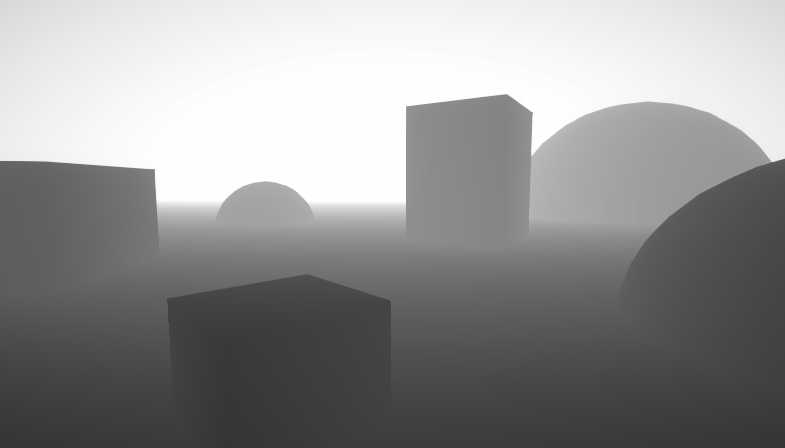
i have a problem with imported meshes in 2022.3.20.f1, with reflection probes. my fbx mesh simply dont receive any reflections. the 3 meshes in the middle are fbx (table, box, and small sphere) you can see the red reflective shader.
the two spheres on the right are unity spheres. Unity's builtin spheres are receiving reflections, my imported fbx sphere not. material is the same. if i set the material to full metallic, it turns completly black, zero reflections.
this has to be the most basic param im not aware of.

when i import into unity6 hdrp, everything is fine

i thought the mesh would be the problem with urp, maybe wrong import settings normal/tangent calculations. but imported as is in hdrp and it is simply perfect.
Hi, I just came up with a nice shader for my game. In Scene View, the shader looks fine, but when Playtesting, the scale of the object is messed up. I used this node setup (Image 1) to achieve a tiled look. The second image (Scene View) is a material I created using this shader. I tweaked a few settings (so that the Voronoi texture is stretched into these lines) and am happy with how the material looks. However, when entering play mode (3rd image), the stripes suddenly are huge.


Static batching can alter object information such as scale
Oh yeah, the object was actually static. Thanks a lot!
Is there a good alternative to scene depth when using the built-in render pipeline?
Why the need for an alternative?
From what I understand scene depth doesn't work in the built-in pipeline and I'm trying to make a water depth shader
I think it should still work in BiRP. Though you may need to configure the camera to generate the depth texture (set cam.depthTextureMode from C# script)
https://docs.unity3d.com/Manual/SL-CameraDepthTexture.html
I have a relatively simple SG "outline" that I'm using to highlight a mesh (including when it's behind other meshes since the unit can be obscured by terrain). I'd like it to be a little less "show through" on the mesh itself. Any tips?
(like the outline isn't really an outline - since you can see it "through" the unit - like around it's neck, chest geometry)
here's my SG

Respected,
this will call on the particle collision....
if (_hit.collider.gameObject.name == gameObject.name)
{
UIController.instance.UpdateCurrentInteractingObject(objectName);
Debug.Log("why2: " + hit.textureCoord + "..." + hit.collider.gameObject);
// If the ray hits the object, returns the texture coordinates of the hit point.
return _hit.textureCoord;
}
this code works fine in the editor.
but when I export the android build..
it returns the default unity cube texture point correctly on collision... but on other meshes it print the name correctly and always return the (0,0) texture hit points on each part collision of the body.
I have applied my shader, but I think it's not relevant to the shader.
I don't know, I didn't get anything relevant to this..
And i am trying to get the solution from past two days.
Kindly guide.
Thanks
Post only to one relevant channel please
how do I get rid of light reflections on material through shader graph ? (Built-in Pipeline)
I deleting the metallic node I read from a discussions.unity thread, but issue is still there.


Do not delete fragment block nodes, instead set metallic and smoothness both to 0
You can add them back by right clicking the space above or below your remaining fragment block nodes
yea a bit better, is there a way to get rid of it fully?
Looks a bit odd going through a portal that's reflecting light 😅
I suppose I could exclude it from this lights layermask , but that would be tedious to remember for each light source that might be added later on near them


It sounds like you might actually want an unlit shader, not just to disable reflections
Just to ensure, while targeting GLES3.1 I am capped at max [numthreads(32,32,1)] for a compute shader, right?
Or even less... Based on this table

It gives 32,24,1 cap, but those numbers "should be powers of 2" according to the internet, so it gives max of 32,16,1 ?
There is no power of two requirement. And you can check this hardware capability using Unity API SystemInfo.maxComputeWorkGroupSizeX/Y/Z
One of the common ways to remove the inner outlines is to make the object shader write a special value to the stencil buffer and have the outline shader not draw when the stencil value is equal to that special value.
But that might require handwritten shaders.
It's tricky in urp though
I've ended up not using stencil at all, just two passes and conditional float variable
I feel like I'm going crazy
Does anyone know where I can look at the Terrain system's WindZone calculations? I am using the WindZone component with my fog shader but as of right now the 'Turbulence', 'Pulse Magnitude', and 'Pulse Frequency' variables are ignored
It does not have to be the Terrain's calculations, I don't actually use Unity's built in Terrain system but as far as I can tell the WindZone component is not used anywhere else. The Unity C# Reference Github page is also lacking in any actual Terrain scripts besides the ones for the Terrain Editor
thas so cool
What's tricky about adding a Stencil block to a shader? 🤔
Tricky in Shader Graph, which is sort of the only reasonable option for creating a lit shader for URP, at least until block shaders are released.
tried to write a simple shader to be able to toggle highlight on/off, then encountered 2 problems, first about actually using second pass, because it just didn't run with or without stencil block. work around by setting 1st pass to "LightMode" = "SRPDefaultUnlit" and the second to "LightMode" = "UniversalForward"
but even then i couldn't get access to SV_StencilRef, so i simply made a float _Highlight property and in 1st pass something like this
            v2f vert (appdata v)
            {
                v2f o = (v2f)0;

                UNITY_SETUP_INSTANCE_ID(v);

                if(_Highlight == 0.0)
                {
                    return o;
                }
I admit - my skills with writing shaders are still quite poor, don't know if this is a valid approach, but at least it works
URP doesn't support multi-pass shaders the same way as built-in. Built-in RP will run all the passes it finds (unless they are a known type for a specific purpose), URP will only run the first valid pass.
so in this case using separate light modes for such effects is acceptable?
or maybe i should ask - what would be a proper method for doing this?
The replacement for multi-pass shaders in URP is mainly the use of Renderer Features. Another little known trick is to add an additional material to the renderer, which causes the renderer to get drawn again with that extra material.
omg i was so blind xD just looked up "Renderer Feature" in docs. that clarifies things a lot, thanks
Idk, making a handwritten shader is reasonable as well, nobody should upgrade their project during development so there is no maintenance concern when it comes to URP changes.
Hm, looks like Render Objects allows overriding the stencil metadata, that sounds like the most painless way with no scripting required.
I'm working on a game that's been released since 2019 and has seen many Unity updates along the way, from Unity 2018 to 2021. I think it's very common to see games, especially in early access but also just actively developed games, that upgrade the engine. Never mind unreleased games.
But sure, if you aren't actively working on the game after release, there may not be good reason to. That's just become increasingly less common with the rising popularity of live service games.
I'm working on a live service game. But we upgraded to a newer version of HDRP only after a couple years, I doubt anyone's upgrading to every yearly release to get some fancy new feature that's better implemented in a third party asset anyway. But I do have a very jaded view on relying on new features that Unity adds 😆
yeah wanted to avoid that because I wanted to keep Emission still working but yeah seems like I have no choice ig. Win some , lose some 😅
Thank you for your help 🫡
Hi! How would I go about setting vertices on a standard surface shader that I get from a float3 structured buffer?
All of the research that I had done doesnt contain anything about using the vert with a structuredBuffer.
I also have the #pragma vertex vert
On the second image you can see how I set the structured buffer from C#
Any help is greatly appreciated!


Afaik you wouldn't use #pragma vertex with a surface shader, but there is a vertex modification function you can add, using vertex:functionName to the surf pragma line. There are some examples in the docs here : https://docs.unity3d.com/Manual/SL-SurfaceShaderExamples.html#:~:text=Normal Extrusion with-,Vertex Modifier,-It is possible

For accessing the buffer I imagine you might need SV_VertexID which you should be able to provide using a custom struct instead of appdata_full
ah I see, sorry for bothering but how would such struct look like? I am still very new with CGPROGRAM 😅
Something like this
struct appdata_custom {
    float4 vertex : POSITION;
    float4 tangent : TANGENT;
    float3 normal : NORMAL;
    float4 texcoord : TEXCOORD0;
    float4 texcoord1 : TEXCOORD1;
    float4 texcoord2 : TEXCOORD2;
    float4 texcoord3 : TEXCOORD3;
    fixed4 color : COLOR;
    uint vertexID : SV_VertexID;
    UNITY_VERTEX_INPUT_INSTANCE_ID
};
That's the same as appdata_full but with added vertexID input
Ah I see, however for some reason I have this error on my shader
Unexpected identifier "StructuredBuffer". Expected one of: typedef const void inline uniform nointerpolation extern shared static volatile row_major column_major struct or a user-defined type
I even tried setting color of all vertices just as a test and it doesnt seem to work, I also replaced #pragma so now it looks like this
I do know that my compute shader is working correctly because I currently have the vector3[] public that I retrieve from the buffer and I can see on the inspector that the Y values seem correct

Might need #pragma require compute / #pragma target 5.0 and I think you need to wrap structured buffer stuff in #ifdef SHADER_API_D3D11 ... #endif iirc
well I tried setting the structuredBuffer inside of #ifdef but then my vert function cant find the "vertexPosition" variable
"undeclared identifier 'vertexPositions'"
I also set the target to 5.0
You would wrap both the StructuredBuffer and where you use it in an indef
but even if I put the function and struct inside of the #ifdef, do I also have to add the #pragma part aswell? Because it cant find the vert function now
"Surface shader vertex function 'vert' not found"
I'm not sure if the pragma part can be inside an indef, but you could do an #else and create a duplicate empty vert()
This might be better though :
#ifdef SHADER_API_D3D11
StructuredBuffer<float3> vertexPositions;
#endif

void vert(inout appdata_custom v){
  #ifdef SHADER_API_D3D11
  v.vertex = vertexPositions[v.vertexID];
  #endif
  v.color = fixed4(0,0,0,1);
}
Ah that might be smart! I'll try it once I log back on my computer, thank you for your help! I'll make sure to tag you if something goes sideways haha
so this is rather amusing given the context but how do I fix it ? the preview limit is set to default 128 why do i need to change it =/

128 seems pretty low for a default, lit shaders often have thousands if not tens of thousands of variants. But I don't know how this preview limit is counting them.
im using urp if that matters? but if 128 is low why do i get this error
oh how many is it likely making?
what would be a good number
I am trying to make a pixleated look for my game using a render texture, but any movement is like drawing on the camera and it stays, making a smer effect
Record a video of what it looks like. But it's likely camera not clearing the previous frame color. I think you were told that in the channel you asked initially.
Is it possible to write a shader that draws a 3d grid(x,y,z axis) in world position? I also need the grid color to be different around a sphere radius
If you want the 3D grid to be visible on the scene geometry, a post processing shader that reconstruct position from depth should do the trick.
I'm not sure how I'd make that using depth values. Also isn't the depth values the distance in the camera direction? The grid may not be aligned with the camera.
Well, if you use shadergraph to make a post process shader, you can even directly use the position node (in world space), that does reconstruct position from depth for you.
But the idea, is to use the depth and the camera information (projection matrix/transform) to calculate the absolute world position.
A big post explaining everything about Depth : Depth Buffer, Depth Texture / Scene Depth node, SV_Depth, Reconstructing World Position from Depth, etc.
how can i create or find cross hatching shader that only applys cross hatching to shadows and rest everything is the same not toon
Hey, I have a pretty simple shader -> https://pastebin.com/fGbK58nv
public void GenerateBlendTexture()
{
    _blendTexture = new Texture2D(Width, Height);
    _blendTexture.filterMode = FilterMode.Point;
    UpdateBlendTexture();
    Sprite sprite = Sprite.Create(_blendTexture, new Rect(0, 0, Width, Height), new Vector2(0.5f, 0.5f), 1);

    _blendSpriteRend.sprite = sprite;

    _blendSpriteRend.material = _blendMaterial;
    _blendMaterial.SetTexture("_MainTex", _blendTexture);
}

private void UpdateBlendTexture()
{
    for (int x = 0; x < Width; x++)
    {
        for (int y = 0; y < Height; y++)
        {
            Color color = _generator.GetTileColor(x,y);
            _blendTexture.SetPixel(x, y, color);
        }
    }

    _blendTexture.Apply();
}
I'm using it like this and texture looks correct but the generated material is just transparent
Pastebin
Pastebin.com is the number one paste tool since 2002. Pastebin is a website where you can store text online for a set period of time.

Is likely related to Depth Priming, which can cause opaque materials to appear invisible if they don't have DepthOnly/DepthNormalsOnly passes.
Some more info here - https://www.cyanilux.com/faq/#urp-depth-priming
Is it possible to make a seamless shader like this via shadergraph?

any ideas where this setting can be found in 2D Urp Data?
Oh, if you're using the 2D Renderer it's not that then. That expects the Universal2D lightmode, not UniversalForward
Can also find the Sprite-Lit-Default or Sprite-Unlit-Default shaders under the Packages/Universal RP/Shaders/2D which might help as a template
alright, let me check that
okay simply removing
            Name "Forward"
            Tags {"LightMode" = "UniversalForward"}
seems to fix the issue
thanks
can somebody help me find a somewhat similar tutorial or at least suggest what nodes can be used?
Does anyone know how to preserve/build Hidden shaders when building? I know you can manually add it on Edit -> Project Settings -> Graphics, but I am making a package and I would rather have them included when they are being used (which they are) but when building they are not present
Hey! Im working on loot indicators for my fps game, basicly every lootable objects has some kind of UI (quad with a texture for now)
Im wondering is it possible to place this quad inside the item mesh and make it see through without playing around with layers?

I only want the quad to ignore the render order for that specific mesh that it is related to
why does it cull the white part of the texture instead of the transparent part?

So let's say I have a character model, and I want one part of it to be sort of wispy. Like it's supposed to look like plasma or some ghost-like element. How would I best set that up?
Would I have some type of secondary texture on the model that defines these wispy regions?
And a shader that uses that uses the value from the texture to apply vertex distortion?
is that one part static? is it's static, the easiest way is to make it have different material, especially if it has different properties from other part material (transparent vs opaque).
Otherwise, you can use a masking texture, but making a shader that could accommodate both transparent and opaque could be tricky (not really, just need to make it transparent and write to z buffer)
you can try using ztest always combined with very big renderqueue value (like 4999) but it will be drawn on top of anything, not just said mesh
you can also modify the vertex z position, nudge it down (or up, check UNITY_REVERSED_Z) so it's closer to the camera
So I have these trail renderers. They do not appear very smooth at low frame rates.

The trails are being moved along a spline. I'm assuming this jaggedness happens because at higher framerates, the large delta time is making the the object jump farther distances.

How can I make it so, regardless of framerate, the paths look relatively smooth?
I'm assuming trail renderers are more for unscripted movement.
Should I be using a line renderer?
yeah, I'd vote using line renderer instead, you'll have more control, although that comes with a price of doing all the trailing manually
It seems like Trail Renderers would be useful when you don't know the path being taken, but in this case I do. I'm pretty sure most of these types of effects have a generated mesh that's supposed to help guide the movement, and a shader that moves it across the surface. Is that correct?
I made a fullscreen shader, which creates this shockwave effect, added the material to the custom pass volume, but in the scene window you can see UV. How to fix it? I tried to use Scene Color, but the result is all white. HDRP


Thanks for the tips but rendering ontop of everything if what Im trying to avoid :/ do you know of sny eay to only render ontop of 1 specific mesh? Without layers because all the items will have the same layertype
You need to use these UVs to sample the scene color. In HDRP, use the "HDRP Scene color" node, possibly with exposure toggle active.
thanks!

Hello!
I have the following script:
void CreateRenderPass()
{
    if (BlitColorMaterial == null)
    {
        Debug.Log("Material is null. The pass won't be created and injected.");
        return;
    }

    // Creates the render pass and specifies it to be injected at AfterRenderingSkybox event.
    m_ColorBlitPass = new BlitPass(BlitColorMaterial, RenderPassEvent.AfterRendering, _RenderTexture);
}
The problem I’m encountering is that in VR, my UI doesn't appear. I’ve had this issue before because I didn’t select the correct RenderPassEvent. I fixed it by using RenderPassEvent.AfterRenderingPostProcessing, and it worked fine in the editor.
However, in the Android build for VR, it doesn't. I changed it to RenderPassEvent.AfterRendering, but the UI still doesn't appear.
Does anyone have any ideas on how to resolve this?
I’m using the built-in render pipeline and pp stack v2, is there any way to make effects like ssao and ssr to work on transparent materials? I understand it’s bc they don’t write depth, but there has to be a way around it. I find it hard to believe that you just can’t have things like ssao work on transparent decals
i know this isn't just me bc i see it in some really popular 3rd party assets, like atmospheric house from finward studios:

this is just... how it has to be? that looks awful
Hello, I'm looking to unwrap a mesh and show the predisplaced vertex position (local bounds) but the Position node value gets changed if I unwrap using this shader graph:

any idea how to get access to unmodified Object Position? I've banged my head about this for hours now with no avail
Connect the Position node (object) to a Custom Interpolator. Then add that custom interpolator node and use that in fragment stage
Example here if needed : https://www.cyanilux.com/tutorials/intro-to-shader-graph/#custom-interpolators-example-1
Thank you so much! I will try this right away
It worked !!


Again! Thank you very much! You're a hero ❤️
I'm sorry if this seems really basic, but for me it's not, I come from Unreal Engine, where pre-skinned local position is a thing
In the case of decals, drawing the SSAO after the decals should work, but I don't know if PPv2's implementation lets you do that. Is it possible to move the decals into the late opaque/alphatest queue maybe?
Probably not helpful, but I know it's a lot easier in URP as its SSAO isn't a post-process but generates a texture (using depth/normal prepasses) that is then sampled in scene shaders.
And the decals feature has a DBuffer mode which similarly puts decals into a texture, then sampled by opaques so automatically applies SSAO.
that screenshot above is actually from a URP project... no amount of fiddling with the render features seems to fix it, far as i can tell
not even dbuffer mode

oh! nvm i was using the wrong shader 🤦♂️
Hey all! I'm currently trying to make a simple 2d "wave" shader for my in-game water, however I am seeming to have a difficult time figuring out how to accomplish a "wave" effect, I keep getting different variations of the liquid's entire UV being moved when it realistically should just be the top area, my current solution is a little bit funny looking and would love any advice anyone would have! I assume I need to mask out part of the UV to just the "top" half but again am not really sure of a good way to do that in shadergraph, ideally it would be based on a float that could be adjusted.


Currently got something "abstract" going on.
With this setup, you are totally overwriting the vertices positions with the mutliplied UV values.
If th eplan is to deform the mesh, you need to add the deformation value to the position (Position node, objects space) before connecting to the position output
Oh, I see!
However, if like I suspect you are using sprites, deforming vertices doesn't have enough precision, what you likely want to do is to distord the UVs before sampling the texture.
If you want a sine wave along the X axis, use UV.x * Time as input of sine, add this to the UV.y (only Y) value to have vertical distortion, and use it as UV input in a sample texture node.
I am currently using a 16x16 white sprite which multiplies with a color to allow it to be changed via code/shader, however it's "height" is controlled via the shader through the alpha channel.
And alright! Sounds good, thanks.
Hey also, just wondering if anyone knows how I can get access to the "Texel Size" node, I can find the documentation for it but can't seem to in the shader graph? Is it possibly only for a particular shader type?
It was renamed to Texture Size
I see! Thank you.
Out of curiosity does anyone know if it is possible to manipulate vector art ui via shaders? I mean like vertex manipulation on meshes kind of animation via shaders?
Do i need to figure out something custom for this or is it just not worth the hassle and i should just animate by other means?
It should be possible with a custom shader. Whether it's worth it or not is up to you to decide.
In ShaderLab, is there an integer range property type?
Like Range() but for ints instead of floats
not that I know of, cmiiw, shader only knows float (not even bool)
I see, thanks!
Is the object to world matrix indexed column-wise or row-wise? I'm wondering if instead of multiplying it by (0,0,0,1) I can just do matrix[3]
Not a property type, but you can use the [IntRange] attribute on a Range (float) property to display it as an integer range : https://docs.unity3d.com/ScriptReference/MaterialPropertyDrawer.html
I'm trying to sample noise from the world space position to create seamless water displacements. This seems to somewhat work in the sense that the noise moves around like a world space shader would but all the planes never align and it doesn't seem to 100% accurately get the noise in world space

If I add the offset given from simple noise onto the vertex position and move the plane it also doesn't accurately follow the center of the plane and seems to go further than it should
To sample using worldspace position, you'd want to replace the UV (so connect to the UV port rather than using the Offset)
Hi peps, i'm looking for a way to convert world position to clip position?
float4 positionCS = mul(UNITY_MATRIX_VP, float4(positionWS, 1.0))
or Unity provides functions that does that for you : UnityWorldToClipPos in BiRP/UnityCG.cginc, or TransformWorldToHClip in SRPs.
Thanks.
Hey, I have a small issue. I want to apply a texture on the tilemap (black one) so I made this shader. But it fills the whole tile instead of following the shape. How can I fix it?


How do you go about hiding internal front faces in a transparent mesh?
Fresnel effect, transparent.

Write to depth buffer first?
Yes, you need to render the mesh with a depth-only shader first and then the transparent material on top of that.
So two materials?
Yes
I would basically be drawing the mesh twice no? Like it would be pretty expensive.
It would be one more draw call, and a much cheaper first pass since it does nothing but write to depth.
Does the write to depth shader need a different sorting priority?
It needs to be in the transparent render queue as to not occlude opaque geometry.
And it needs to render before the fresnel material.
Hey so I was watching some rec room videos, and I was wondering if there's a way I can achieve this type of lights in unity

I know that the game is made in unity but nobody else has been able to figure out how to gets lights like this and I'm trying to see if someone can help me achieve this
Also something that I find cool is how they fade out
Hi, not sure if this is the right subforum but anyway... this happened after I merged two projects. Is it possible to solve without making new materials? The color is still there, it seems. But I can not make it red again.


try to Reimport
Asset/Reimport or ReimportAll?
Reimport
I select the material and choose Reimport and nothing happens. No dialogue etc ... how does unity know where to reimport from?
Reimport repeats the process when you import something into Unity
are you sure there 2 projects have the same render pipeline?
Is there any documentation on how to create HLSL shaders that work in the full screen render feature?
I'm trying to create a blur shader and im having no luck with the shadergraph approach

No sorry, I am supernoob. Where do I do this?
Edit-Project Settings-Graphics
No they didnt. The lower one is the project ("None..") that is imported to the top one ("Unversal..."). The imported project is the one that has the materials and objects. The first one is for a VR setup.
How can I fix this?


change the material shader to URP/Lit
turns white. If I do the import all over, could I do something to make it work from the start?
unless there is an easier fix
Edit-Rendering-Convert Built-in materials to URP
didnt work in current project. Should I do this beforehand?
maybe try select the materials and choose "Convert selected materials"?
I tried, makes it white
Im going to try to do it all over, how do I make them have the same render pipeline?
^ any ideas
standard render pipeline. trying to create a dynamic normals texture using a shader that current outputs a dynamic color texture.
is there any way to set up multiple render targets that can be targeted in the built-in forward opaque pass? perhaps using command buffers? i have the command buffer set up and verified it's working, and have tried to set the render target before forward opaque, but the dropdown for multiple render targets is disabled in the frame debugger.
edit: i figured it out, can't use command buffers to mrt for the entire camera. gotta be use cam.SetTargetBuffers(...)
this thread helped me understand.
That looks like simple cone meshes with additive transparency tbh.
yeah but they fade out and ive been trying to figure out how i can get that to work
Is there a way to create bloom for specific objects without HDR and multiple cameras? I have a circle countdown effect that needs to have a bloom effect on user's profile picture. Since it is a "Filled" image (it changes depending on the remaining duration), i cannot put a static glow image. I also cannot use different cameras because the UI layout is really complex. I did achieve it with HDR but i've read that HDR can hurt the performance (i'm really not sure about this, i can use it if it does not make a large difference), and the game is going to be played on low-end mobile devices too.
You mean on the vertical axis? You can add fading to your shader, something simple like alpha = saturate((positionObjectSpace.y - _LightFadeFloorHeight) / (_LightFadeCeilingHeight - _LightFadeFloorHeight)).
Also you will probably want to add a distance fade so the light cone fades to zero as it gets closer to the camera.
Does ztest in shadergraph work? seeing "always" as normal (LEqual) :/

The short answer is yes, but depends on the context. Would be good to see screenshots of exactly what you're trying to achieve, but the likelihood if if the geo is simple enough you could write a UI shader that fakes the bloom
Any idea why this thing is stretching the texture at the top and on the face it's not showing the tiles "vertically"? I basically want the same size squares for the whole object. I tied triplanar too but that is producing some ugly artefacts (like extra gridlines in the middle of another grid etc). Any ideas how i can fix this?


You're using a 3D coordinate for 2D UV input, which means it's truncated to just two dimensions and so projected along one axis
So, planar mapping which is much the same as triplanar but with less dimensions
so planar mapping... I'm assuming that's not a node huh
No, but it's as simple as taking any 3D position and swizzling the three dimensions into two
Which you're more or less doing here, I mean
oh hmm... ok i put the position into a swizzle and the mask... well i'm trying the different permutations... so far they still stretch at the top
I may have been unclear
You are doing planar mapping, which will always stretch with a 3D mesh because the projection plane is 2D
oh! i thought that was the solution i should be looking for...sorry misunderstood you there
so what do i need to do to fix this?
Creating a grid from 3D position directly would give you the most accurate grid, though since the rounded arch doesn't really conform to any grid it might look weird but I'd still try it
Another option is to UV unwrap the mesh precisely for a grid texture, so you can prioritize making it look good rather than "exact"
Position can be turned into a grid quite easily by repeating it with fraction or modulo, and then using Step or Smoothstep on it
not gonna lie, 1) i'm crap at unwrapping models and 2) i have a lot of different meshes of sizes etc (which is why i was looking at the shader option)
when you say repeating it you mean splitting the 3 axis and passing each of them into a fraction or modulo and then into step?
That'll work, but might not need to split
hmmm this is basically creating the grid and putting it on top of the texture. I think i understand what you mean... generating the grid procedurally
here

yeah i don't know what I'm doing tbh... i just tried triplanar again (even though for some reason a few tutorials warn against using them a lot because of performance)....If i can fix those weird looking faint lines in the middle, I'd settle for that

You could try doing something like float p_fract = fract(position)*N; return min(min(p_fract.x, p_fract.y), p_fract.z) < 1 ? black : white;
(which should create a 3D grid eather than mapping 2D grids)
Though ig if you need to use a texture it won't work
yeah i still need textures 😦
Can you not just UV map your tunnel?
i've tried in blender but 1) i realised i'm crap at uv unwrapping and 2) i have a ton of different shapes and sizes (it's basically a modular set for a level creator for my game)
so if i can avoid spending a month unwrapping these things by doing a shader, that would be optimal haha
or at least that's what I thought
Triplanar has a setting to choose how smoothly the textures blend together so by setting it to maximum (or minimum idk) you could make it jump sharply without any faded lines
yeah the blend float... that's the best I could get it... still looks a bit off but I might have no other option. Are triplanars that heavy? I've been reading not to use them a lot due to performance
even old mobile gpu (opengles 2.0) can sample up to 8 textures simultaneously, so I think triplanar (which samples 3) should not be that heavy
as for your blending problem, you can simply add step function the texture interpolators (if you have access to them)
hmmm when you say access to them what do you mean? I'm on URP and this is a lit shader.
Are the grid and textures not separate problems?
Triplanar looks perfectly adequate for most textures in most situations
The grid could be procedural instead
The rounded arch won't be on a grid though no matter how perfect the grid itself is, as I mentioned
This is the result of the triplanar with blend set at 200 (not sure why i needed such a high number but at least those weird middle lines disappeared)

doesn't look too bad if I can have hundreds of these meshes (basically to make a level) and triplanar doesn't cause issues with performance
That's functionally the same result you'd get with a procedural grid
hmmm... well if i can still use a base texture and a normal (and have advantages to using triplanar), I'd be interested to explore it
Wondering how can i get displacement from one float4. Normally, i'd subtract a vector to the relative position but i'm wondering if it's different with float4.
Could definitely achieve that with a shader yep. I would make the shader render the circle w/maths, then inside the shader do the circle trimming and bloom.
i'm pretty new to shaders so any doc/help would be appreciated
Hey,I've been trying to make a cartoony-like outline shader for my game and instead of getting the edges to have a smooth black outline,they just pop off the object (no matter what width I set for the outline) and it becomes a black texture.
Can anyone help me?
Here's the script for the shader: (URP-Shader btw)
https://hastebin.com/share/afisabusoh.cpp

Hastebin is a free web-based pastebin service for storing and sharing text and code snippets with anyone. Get started now.
I have a problem with my shader. I´m working with Shader Graph, use Position node (absolute world) for my decal as to have nice seamless tiling whenever two pieces meet. But I found a problem when rotating the decal itself, for some strange reason the normal or the lighting seems off, as if the normal is transitioning to the inverse and back.
If anyone have any idea, I would really appreciate it.

Seems like the normal output space for decal graphs is always Tangent space, which is only correct when using the regular UVs. You might be able to use a Transform node before connecting the normal though, not sure
URP does not allow multiple UniversalForward passes in a shader. You can do one without a lightmode tag but it'll break SRP batching compatibility. It's better to apply the outline as a second shader/material or use RenderObjects feature.
As this technique pushes vertices out using normals, faces will also become unconnected if the model is flat shaded. You'd usually only use it with smooth shaded models.
damn,didnt know that, thank you very much for your response,I've found a already done unity asset from the store but it is for Build-In Render Pipeline,I guess I'll try that one,Tysm again!
or I could try the feature u told me about first,I dont really wanna stay and convert everything for a outline
Thanks, but cannot make it work with a transform node. Tried every option.
What is the equivalent of URP Sample Buffer in unity 2020, it does not exist in the version i use

Depends on the method used to apply the shader, but likely to be sample a texture with the _MainTex reference on earlier versions
yea im doing it but ain't getting a similar result
why is it working fine in 2022 but not in 2020
 I've made a URP Outliner with a shader graph,I can see it while in the editor but when I go on play mode I cant see it no more,I think I should do something with the camera's settings but I don't know what.Can someone help me?


-Closed- I managed to make it work by multiplying the step with the logo sprite and then applying the result
Hello Everyone!
I'm having a little problem while following a tutorial.
I'm following a GabrielAguiar Tut, and i have that problem making the shader, but i'm starting to learn about shaders and VFX
Someone know how to fix that?
Hi. I'm trying to put a "decal" on a wall and be able to control the sizing and positioning of it... that all works but I'm getting that stretching that you see on the x and y (if i scale the texture down)... I tried removing it with smoothstep and this somewhat works but most of the detail gets lost. Any other way I can remove those? (I know there are other ways to do a decal but I'm trying to avoid that route if i can)


Looks like the stretching is from the texture clamping. Should be able to fix that by either :
- add fully transparent pixels around the edge of the texture (and enable the border mip maps option on texture to preserve that at other LODs)
- mask the decal to a portion of the wall - i.e. use Rectangle node with same UV input. Multiply that into the value used for the Lerp T input
Oh also should use the clamp wrap mode on texture itself rather than clamping the UVs (otherwise with bilinear filtering the bottom pixels still interpolate against the top, hence why its darker there)
oh damn ok so setting the wrap mode to clamp got rid of the Y stretching at the bottom (for some reason)

so I basically need to make a mask from the alpha of the texture if i'm understanding right?
oh wow ok that worked! 😄 thank you so much
If you're using a Custom Function node calling that LinearToSRGB function, then it might be you're using the Built-in graph target (render pipeline) which maybe doesn't have that, not sure
If it's just on an input/output to that function you could move it into the graph itself using the Colorspace Conversion node
How are you applying the outlines? If it's a renderer feature and you have multiple Renderer assets it might be the editor is using a different one to the camera?
Make sure you set the Reference field of the Main Texture property to _MainTex (under Node Settings tab of Graph Inspector while property is selected)
yup it was, also there was a missconnected node that i also solved but no luck getting shadows 😦
this is the shader graph,I dont know really what it is,maybe you figure it out from this.

Might be static batching. I'd probably suggest looking into other outline techniques though as this'll only really work with simple shapes like cube/sphere
I'm using just default nodes i guess...

Btw i'm using Unity 6
Hi, when using the Camera node to figure out the distance from the camera's position, it's using origin position (0,0,0) rather than the camera's current position in the scene. Any idea how to fix?
Hi so I'm trying to make this custom hlsl function node work in shader graph, and I can't seem to get an output out of it


whatever I do it won't create an output node for it, error message included in the screenshot (no 3 parameter matching function at the moment. Is anyone able to give me a pointer? I've tried including an out float in the hlsl function definition also
Custom functions only accept void types, to provide an output use an out parameter, not a return type
So for example void InsideAnyCircle_float(float3 worldPos, float circleCount, out bool Out)
Though you also use bool in code but Float output on node, so be sure they match
It happens when i put "color" node on the Multiply

And that's the config of the Node... I don't know why i'm getting this error


ok thanks, I've been at this a while 😅 however, I still have no output (no errors though) using float


Try hovering over the node and clicking the arrow that appears in top right, you might have collapsed unused ports
If it doesn't appear, maybe try removing and readding the output or creating a new Custom Function node
oh god damn it
hahaha thanks so much
I've been going through loads of different iterations of possibilities
and probably got it right a few times already and didn't know I'd collapsed the output
Seems like a bug. Might need to try a different version
iirc the Camera node only works in URP. If you're on other pipelines :
For HDRP you can just use World positions as they are already camera-relative.
For Built-in, maybe try a custom function with Out = _WorldSpaceCameraPos;
i'll try on 2022. But i don't know... :/
I'm using URP. It works perfect in scene view but not in game view which is confusing me
in editor outline shader working good but in build it looking like this ( using URP with Forward+ render)
I tried to change render queue too but it didnt fixed

Hello
So I'm using Shader Graph and GPU instancing by using the Graphics.RenderMeshIndirect(). Everything works fine in the editor window and play mode, however, when I create a build, I don't have any shadows on scene
I'm using the method provided by Cyan https://www.cyanilux.com/faq/#sg-gpu-instancing
I have no clue what I could be missing, and Im not even sure where to start looking at this, any idea on what could be a good starting point to find the issue? The directional light looks fine (no weird rotations or parameters)
Found the issue
It was because I had changed the instance key from multi-comple to shader feature
reverting it fixes the problem
so, I am making some animated noise to distort a world space shader effect, however with my config of nodes and stuff, instead of the noise middle staying the same, as the noise multiplier increases the noise drifts off in XZ... I assume because of the noise adding onto the world position. But i've tried a couple of things like subtracting 0.5*noisemultiplier and stuff and it hasn't worked. Any fresh eyes see where I'm wrong?

I'm working on a sprite shader based on sprite default lit, but my outlines end up different from the base material, and I'm not sure why. What exactly decides the edge of the sprite as shown here?


The left is just, sampling the texture and directly outputting it as color and alpha. Shouldn't that produce the same outline as the sprite default lit?

I'd assume the default sprite shader is discarding/alpha clipping in it's editor outline pass and shader graph isn't. Probably can't do anything about it
Hm. Will it affect anything visibly, or is it just a quirk?
Shouldn't affect anything visually beyond the outline (and maybe what parts you can click to select the object in editor)
Alright, thanks
Also, when using normal maps in the shader graph, the results are visually different from what I expect
depending on the "type" I use I get different results


however neither is what I expect
What is the correct way to sample normal maps in 2022? I don't recall it being like this in 2021
Would depend on what range of value (and distribution) the noise texture has - subtracting a value of 0.5 assumes that's roughly the average value.
Importing the texture as sRGB vs that tickbox unchecked may also affect things
The one on the right is correct (Type : Normal) with textures marked as Normal Map, it's supposed to look like that as the values has been remapped from the 0-1 stored in texture to -1 to 1
I see, so this too is just a visual quirk in the previews and such
Wait, there might be something else here.
These two point to the same texture. In that case, whichever one I sample shouldn't matter, right?


But it does, it only creates a functioning normal map if I go through the _NormalMap
Is the _NormalMap treated in any special way prior to being loaded into the graph?
I really don't see a tangible difference between these two...


There are some special references which are swapped out automatically when assigning the Sprite, _MainTex is the main sprite texture for example. I think any other maps depends on how what "secondary textures" are assigned to the sprite
https://docs.unity3d.com/Manual/SpriteEditor-SecondaryTextures.html
Any other texture references would be assigned on the Material itself - and if you created the material before changing the Default field it will still use the old value, the Default is only used for newly created materials (and the automatic material asset under the graph)
Ah, so my default texture doesn't work because I added it after I made the material
Yea, but you can still manually assign it
The arms would need to be UV mapped or use vertex colours. The shader can use one of those to determine which parts to fade
it is uv mapped
Right so default textures aren't used in the case that no texture is assigned. They are just used when creating a new material to fill the slots

Then you could create a gradient texture and use that to control the alpha in a transparent shader
cause in the shader i want two floats
to control how high up the arm the fade starts and ends
Personally I'd apply vertex colours to the mesh, it would be easier. The idea is to paint one side of the arm black and the other white (with appropriate greyscale values for vertices inbetween).
In the shader you can remap that into a 0-1 range using start/end floats (in Shader Graph would be Vertex Color node then Remap or Inverse Lerp. Use that result to control the Alpha)
Hello, why does the "Object" node in shader graph return 0 for the bounds size, min and max?

I've tried this with a primitive sphere, and when I debug, it's always 0 (black for all of the inputs, except Position and Scale)
It only functions in URP/HDRP, not Built-in
aha, that would explain it, ty very much again @regal stag life saver
so there's no way to get the bounds (except feeding via script maybe?) in non URP/HDRP projects?
a better question would be (since I'm new to Unity altogether) should I use URP instead of built-in renderer?
Correct, you'd need to pass it into your own properties via C# script. Though that means different material instances per object, which isn't great for performance in Built-in RP. It's better in URP/HDRP because of the SRP Batcher optimises setup between draw calls for materials that share the same shader
Yeah, better to use URP. Built-in RP will be deprecated in future versions (beyond Unity 6)
Okey dokey, thnx again @regal stag
it was the sRGB checkbox, thanks again! 🙂
How possible would it be to apply different level of a pixelation shader to different object? I’m working on a 3d fighting game and want to change pixelation of individual object dependent upon health

Alrighty so, I'm on Unity 2021.3.43f1 and for some reason I cannot create a shader graph

I'm sorry if I've missed something obvious, I'm just getting into unity as it's a requirement at my college and I only really have experience with Godot lol

im trying to find a video on how to apply the vertex colors to mesh
When creating a project using the URP or HDRP templates, they come with shadergraph preinstalled. For Built-in RP projects you can use shader graph (Unity 2021.2+ iirc) but need to install it via the Package Manager (under Window heading on top bar)
could u help me out?
im not sure how to do that
what part are you struggling with?
trying this in the 3d package or in unity?
wdym
is this a mesh you are making in something like blender you want to apply vertex color to
or something where it has to be done inside of unity?


select vertex paint mode up here
then you can just select the color you want and paint the verts that color

select the mesh not the rig

yeah you can just paint the verts what ever color you want see here i got my top verts white, bottom ones black
whats your shader in shader graph or hlsl

i havent made it yet
i got multiple verts here
its not just a long cube
isnt there a way to do this without this whole vertex painting?
just with a shader in unity
since i got the uv map


i have no idea what this is
or what im doing
would google like vertex painting and blender or something then
did a test with multiple edge loops lioke yours as well

show me how its cut


i just painted the very left black, the next loop slightly brighter, the next loop a lot brighter then the right side made it white
what do i press not
set color black paint the verts you want to be black black
yeah can click and hold, jsut make sure its from a angle where the vert is visible


it looks weird
its not consistant
yeah you can just figure out the ideal color to set each loop to
like did my with loops and just figure out the inbetween values eye balling it

could also math out the values if you want
since you know the value got from (0,0,0) on the left to (1,1,1) on the right
and you know total length of the object and where each loop is relative to that length
then how would i even go about making the shader
well can access this data in the Vertex Color Node in shader graph
can just use the values from vertex color to adjust your alpha in the shader
Could make a thread
@royal bloom should follow a few simple tutorials on shader graph first
Are you using Builtin, URP or HDRP? And is it a shader graph?
standard unity shader
so i believe builtin?
Is there a (free) way to debug vector values in shader graph? like draw the coords values in the preview window?
Edit: nvm I have found an hlsl code snippet in github that debugs floats
You can debug shaders with Renderdoc.
This is what I wanted

I'm new to Unity, does Renderdoc do this?
Renderdoc lets you step through the shader code line by line and inspect how a screen pixel you picked was rendered.
How do I tell a shader graph how to behave when handling sliced sprites? I want to create a 9-sliced shader that should tile the middle piece (used in a line renderer). Basically I want to emulate how the SpriteRenderer interprets sprites when set to "tile".
Im trying to rotate a vertex based on its new offset position and a given origin. The aim is for the vertex (imagine a plank) to always touch both points. I have calculated to correct angles, but im struggling to use two RotateAroundAxis in a row. There is probably an issue with pivots? Is there a better way ?


Haven't really used sliced sprites, but I think it alters the uvs so should be automatic, maybe?
It's not only altering, it's spliting the UV into 9 different sections. I don't remember if for the image component it does it by spliting the mesh in 9 or if it is purely pixel shader based though.
But it can be done with a pixel shader.
Happens that I'm doing this currently on a personal project, let me fix the last issue I have and I can share it 🙂
the aim is something like that

Ah I misread the question. Yeah I think for the image component it does change the mesh itself

0 is top left
What do you mean? Which 0?
Thanks, that's very cool. It does do an awful lot of tiling along V in my case though, which is not what I want. Not sure if I did something wrong.
Looks like way less nodes than my solution though 😵💫

If it works, don't fix it :p
Well it doesn't, that's why I'm asking here 😄
Because in my case the middle section repeats the whole texture, not just the middle part. So the edges are repeating in the middle too.
Remapt the middle section value to the min and max coordinates of the middle section
I'm not very good with shaders so I don't know what you want me to do. :/
Sorry if it still very messy, here's my reinterpretation of the 9sliced UVs
What I tried to say was :
If the middle section repeats the whole texture, it means that the UVs you've generated for the middle section range from 0 to 1.
But you want them to range from the min UV of the middle section, to the max UV.
So you need to remap the values, the easy way to do it would be : UVMiddleSection = lerp(min, max, UVMiddleSection)
You give your texture atlas to this shadergraph, it will slice it for you and the index you give it will slice the atlas accordingly starting from top left for index 0
@civic lantern

i made the shader graph
how would i even start
i made a lit one
Look at tutorials and/or existing shaders
You also need to enable transparency on it, probably somewhere in the Graph Settings
Then you should be able to create a Vertex Color node and plug it into the Alpha in your Fragment output

surface type?
Yes
can someone help me make a shader to fade my mesh?

i painted the vertexes in blender
now i need to make a shader graph to convert the colors from 1-0
1 being black and 0 being white
and then have a start and end float
which will determine when the fade of the mesh will start

trying to achieve this
URP Lit shader supports semitransparency via the base texture alpha channel
You don't need a custom shader for it if you use the texture alpha instead of vertex color alpha
i dont understand sorry
could u explain it more
im really new to shaders
i just need two values which i can modify
the start end end of the fade
If your mesh is UV unwrapped to use textures, you only need to make a material asset that uses the urp Lit shader, set it to transparent and assign a base texture that has your fade in its alpha channel
i have a uv map
for my arms

oh yeah its unwrapped
if thats what you meant

i made a material
of the skin color
is that fine?

i set it to transparent
but what do you mean by the base texture
i cant just have a fixed texture
i need to adjust how much it fades
with two floats
like i said
You would draw or bake the fade gradient on the base map texture's alpha channel
can i do that during runtime?
im constantly going to be changing it
how much the arms fade
where the fade starts
Not any more than with vertex colors
If you do need to remap the fade in some way then you will need a custom shader
It seems you need a bit more understanding of what materials and shaders are and how they're made before you can practically implement our advice
And for you to describe in precise terms what you want
i just need to be able to achieve this

also be able to control where the arm starts fading away
and where it finishes fading
In the shader you can remap that into a 0-1 range using start/end floats (in Shader Graph would be Vertex Color node then Remap or Inverse Lerp. Use that result to control the Alpha) ```this is what someone wrote above
hi for some reason my base map isnt lining up to my model, ive never had this issue before and i was wondering if anyone new what ws wrong. i UV unwrapped it in blender and brought it out and plugged it into the base map

that might also be possible via Scene Depth as well. do you want the arms to always just fade away near the ends, or is it just about things being close to the camera fading out
it not about things being close to the camera
my camera clipping is set to the lowest value
well i want the floats from 0 to 1 (or sliders from range 0,1)
so i can set it when i want the arms to fade
you need to compare the clipspace z to a value
o.color.a = smoothstep(0, _whereYouWantFadeToStart, o.vertex.z);
I'm looking into foam and I'm having an issue regarding depth. Here's my node setup
I'm assuming the issue is that obviously the closer I get to the foam the less depth the scene is going to have and the further I go away from the water the more depth it has so the less foam there is. The issue I'm having with this is foam only shows up at a certain depth (and is cut off further away). I was thinking of increasing the depth and trying to limit the reach foam had but I don't know how to go about limiting the reach


DepthFade sub graph

Generally speaking my DepthFade node doesn't really seem to stay consistent and it's annoying. Maybe the DepthFade node itself is the issue
Nevermind for some reason getting rid of the camera far plane multiplication and plugging the scene depth in just worked
Does anyone know if there's any difference on the results between Vector3.Cross and cross of shaders?
Or between Vector3.Dot and dot of shaders
I wrote some simple code that worked in the CPU and for some reason on the GPU it's not working
its the same operation
would look into other differences since a dot or cross given the same inputs will have the same output does not matter if CPU and Vector3 type or in shader
You may post the relevant codes here if you want us to take a look. Notice that CrossProduct is oder dependent so if you do the operation in wrong order, the result will differ (should be the opposite vector if I'm not mistaken)
Thanks! yeah i didn't have much rellevant code to show, I was just wondering if there was any. I think there's some stuff about vectors being or not normalized returning diferent results on GPU or CPU
It ended up being a diferent issue 🙂
not a huge surprise since those vector operations are just simple math operations without any differences
I have a simple shader that makes some rectangles. Do you know how to increase the spacing between the rectangles?

What effect is your end goal?
its a shine effect for pickup object

it looks decent already, but I wanted to increase the spacing between the "stripes" to make the effect more subtle
@lusty smelt This is for the highlighted area, it scrolls over time and you want a bigger gap between them? I'm not in unity to try now but I think you need to adjust the rectangle. You want either the 0 or 1 to cover more space. Play with the rectangle sizing?
already tried that and it does increase the gap, but also makes the rectangle stretched and it doesnt look that nice. I would be perfect to increase the gap without changing stripes width
Do you have video clip of the effect with how it is now and what was bad?
Figured it out ;) I changed the Y tilling and then adjusted the size of the box
If I want to get the position of the actual object in shader graph, what are my options?
Just pass it in via script?
If the object isn't static/dynamic batched, can use the Position output from the Object node
Ah kk. I'll use that if I find I need it.
Trying to make a pie chart.
So taking a cylinder and cutting it with alpha clipping.
Does anyone know how to do this in shader graph so that the noise effect below is performed equally on "standing" walls (it goes from top to bottom without stretching)? Similarly on the top and bottom walls.

You need to implement a triplanar sampling.
Mornin all, would anyone know if such a thing as Tesselation for URP Shadergraph exists? Maybe a custom function? Had a look around but the only things I can find are HLSL Shaders that don't really do what I need. I did think about looking converting the tesselation part into a custom function, but I know nothing about HLSL, so pretty much a non-starter. 😕
I'm trying to recreate the analog channel change effect for swapping between two textures on a retro tv like they do here in premiere: https://www.youtube.com/watch?v=Tbk9GwoTUNA
It's a work in progress but coming out nicely.

Try Epidemic Sound 30 Day Free Trial : https://share.epidemicsound.com/9ulrss
Looking to Buy Premiere Pro?
https://clk.tradedoubler.com/click?p=265883&a=3281779
My Filmmaking Gear :
The Best All Around Lens for APsC Camera's :https://amzn.to/3Jvac0u
One of the Best Budget Camera's Ever Made: https://amzn.to/3YEHqPs
The Best Cage for the BMP...
What node are you talking about? The flipbook-node does not change when I plug in my texture.
I am doing some experimentation to 'blow up' models in a full screen shader graph.
Here I want to extrude all objects in a scene along their normals. I tried to take the position and add the normal to it, but this did not work in a full screen graph as that is just color data.
Another idea I had is to slightly enlarge the normal UVs, so it kinda zooms in. This does not work the best sadly, so I wondered if someone here has smart ideas
A vfx graph would probably be better for something like that
I think I did not explain it correctly. Not blow up as an explosion, but more like a balloon you can inflate and deflate (with object shaders this is relatively simple since you can just change the vertices)
It doesn't seem possible in a full screen shader since all the meshes are rendered already
Screen space outline shaders have to work in a bit of a different way
What Spazi said.
Why would you try to do that in a full screen shader?
Ah yeah fair enough
I wanted to add this as a post processing effect and have it interact with a screen space fog solution this way
Interact in what way?
You can render to a stencil buffer or something and use that in the fog shader.
Have fog not render if you look right next to objects. So the scene fills with fog and then if you look next to a house there is a small offset for the fog. Just using depth does not cut it, so I am trying to get it working with the position and normals now
Wdym by "look next to an object"? Look directly at them? Or look somewhere else, while standing next to them?
Fog "offset"?
You can perhaps do that using some distortion shader, but your blown objecf would be blurry and stretched
Anyone can confirm this is not possible to solve?
@regal stag suggested could be the normal output space for decal graph is always Tangent space.
I tried using a transform node, as he suggested but it did not work using any of the options/convinations.
Anyone has any idea if its fixeable?
Thanks in advance.
Doesnt seem to be available for URP:
https://docs.unity3d.com/Manual/SL-SurfaceShaderTessellation.html
And I doubt it can be achieved with a custom function since tessellation needs its own shader stage (?)
Meant to reply to you
Yeah from everything I've seen Tesselation isn't natively a part of URP which is a pain and a half. And every tesselation shader I've found for URP is HLSL.
Buuuuuuuuuuuuuuuuuuuuuuuuuuuuuuuuuuuuuuuuuuuuuut.
I've just had an intriguing thought (I was hoping to use tesselation for an ocean shader)............but may if I used a 'flat' terrain (because it has dynamic subdivision), that my be the way to go with a general vertex displacement?
Sounds like a hack but maybe it's worth trying
Oh it's definitely a hack. lol. But yeah, will give it a go when I'm done with my current thing.
Not sure if terrain shaders support vertex displacement but maybe
Terrain takes up a good chunk of performance tho. Having LODed high poly quads with the water movement being in world space might be a lot more performant
URP can just batch them together if they use the same material/shader
Yeah, was thinking that. Just need to make sure that the seams between different LODs dont have gaps
Make the edges higher poly than the middle parts maybe?
In theory it might not be noticeable if the further meshes would displace less
Also a good idea, thats what I did with my custom terrain
Or you can make the simulation world space, but have the water 'follow' the player. This way you have just 1 object with a high poly center and lower poly outsides
That's how games most often fake infinite water
Yeah I did look at using planes, but tbh, the concern about that is the sheer amount of them I'd need and the polys counts on each of them when the player is close.
I doubt that terrain would be any more performant
Feel free to try both of course, but in general I steer away from terrains except for rapid prototyping
Was looking at this video specifically.
Hello and welcome to, like, the 10 millionth water tutorial I’ve done. In this week’s video we’re looking at some more in-depth Unity Shader Graph features to make water, or an ocean, with shoreline/edge foam, depth, and waves.
Shader is compatible with HDRP., Edit: it used to be compatible with LWRP but Unity changed something. I'll update t...
If the water always is at the same height, this might be worth a shot


Yeah, pretty big area to cover. lol.
Would be much easier if they implemented Native water into URP. lol.
Why can the box be seen from some angles and from some it cant


the black walls
i wasnt sure where to post this sorry
Is this box made of multiples meshs ? Or a material per face ?
I used the same box as the one on the left of it and deleted the front face
i made it in blender
the whole thing is just made out of one material
Could be an occlusion issue, do you have some other views of the scene ?


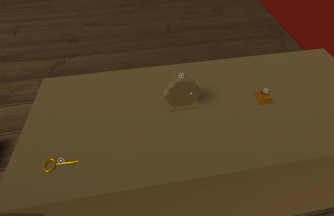
What's the best way to achieve similar "fake ambient occlusion" in 2D?

At first I thought to just make the walls glow around contour (similar to how blurred outlines work) but I will have cases where the floor should be perceived as being way below the wall (like on a bridge) in which case I wouldn't want the walls to glow black all over the open space
Ideally it's the floor that gets darkened when cornering a wall, not the other way around, but I'm open for suggestions
Alternatively I guess I could pass in the wall shader which side it's supposed to glow dark
And cut off sides that shouldn't simulate ao
see "inverted normals" pinned in #🔀┃art-asset-workflow
alr thank u
Are you using tilemaps for this? @fast shore
In that case would be easy to make them separate tiles in Tilemap, you can control them with rules.
No, custom renderer, that why it's such a problem
And wall chunks are combined into a single mesh
Also even with tilemap I don't see how that would've helped
You can also draw bridge elements with higher render order to cover those
Tilemap rules can extend several tiles out and you can have outer "empty" shaded tiles
That might be a low-effort solution tbh
Yes, I was looking for information on how to implement it and that was it. Thanks for the tip
Hello, I have a question about an MR project, it's an Apple Vision project that has an AR part and a VR part. At one point I have to deform the environment like this, it works in editor, but not in build. To do this, I use the scene color node. But as my project is configured to be in MR, I think it won't work... Is there another way of achieving this effect without using scene color? Or with a shader designed for MR projects?

In Shader Graph, there is a scene-color node. What is the shader lab / hlsl equivalent? Is it possible without using a render texture? Please tag me if you have an answer, thanks :)
If you're on BiRP then I assume GrabPass is what you would use
And for srp?
Are you making your own SRP?
No I mean urp
It samples _CameraOpaqueTexture
Specifically if using the URP ShaderLibrary includes, you'd use DeclareOpaqueTexture.hlsl
Thank you, do I have to clone this github repo into my project or is it already included?
It's already in the project if using URP. But you can only include it if the code is written specifically for URP - using HLSLPROGRAM and universal includes, not CGPROGRAM / UnityCG.cginc.
pow(f, e) will not work for negative f
why cant we use negative numbers ?
Okay tanks, is there any way to configure unity to automatically use HLSLPROGRAM, instead of CGPROGRAM?
it should work I think, odd e should result in negative value, while even e result in positive
thats the error i get, according to unity docs pow with negatives produces NaN
The pow function in HLSL does not accept negative numbers as the first parameter because it results in undefined behavior for non-integer exponents. When the base is negative, and the exponent is a non-integer, the result is a complex number, which cannot be represented by floating-point numbers used in HLSL
The result of a complex number arises when raising a negative number to a non-integer power due to the properties of exponents and roots. When you raise a negative number to a fractional power, you're essentially calculating the square root of a negative number, which is not defined within the real numbers.
shame they cant add support to return a float2 so you can get complex numbers if you needed it
That would require new hardware that is capable of that, as well as changing the API specifications.
Something like that would blow up all the related infrastructure.
pow and ipow 😏
Hi! Does someone know how to make a smear effect ( anime style speed deformation effect)? Its a very popular fx
There is this discussion onthe forum but no one seems to know how: https://discussions.unity.com/t/does-anyone-know-how-to-convert-this-smear-shader-to-work-on-a-skinned-mesh-renderer/889572
I contacted creator of Realtoon shader and he also think it would be a great addition but he need some kind of guide code for it.
This forum post you linked provides a shader and script that purpotedly does it, did you try it?
Their issue is making it work with skinned mesh renderers specifically
The effect itself is quite simple
A script stores an earlier position of the object
Shader offsets some of the vertices towards that earlier position's direction, masked by noise and normal direction to offset direction
Hello there! I'm looking to use baked lightmap information in shader graph (using URP !) to get a mask that separates the bright from dark of my scene. Any suggestion about how to do this ? I still can use x sample texture node as parameter and go from there but I'm pretty sure there's better way to do this ! I've seen some "2D light texture" node for example but still finding how does it work and if it's really relevant for my using !
Thanks in advance !! 🌺
2D light texture is only relevant to 2D lighting of the 2D renderer
Sounds nice, thanks !!
Hello !
I made a custom shader in which I made a function to recalculate UVs as quadbilinears. I am using double (64 bits) values for high precision calculations. In AMD & Nvidia GPUs I am using it works well but in a Intel Arc A770M it doesn't work out. How am I supposed to know if this GPU supports 64 bits ? Is there some concrete documentation or information to understand that ?
Would suggest if you have code that works on AMD and Nvidia but not on that GPU, that is a good indicator that it either does not support, or has a bug in its implementation
Yes I want to use it on skinned Mesh renderer. If I could have a guide code to give it to RealToon creator it would be very usefull because he could combine his shaders with the effect.
There is only one shader in the asset store that do smear effect but it is not a toon one and my project already rely on realtoons shaders
I realized I don't actually know how texture samples work. Outside of memory usage, is there a difference between sampling a 4x4 texture versus a 4096x4096 texture? I can only assume that there is, but where is that measured, if anywhere?
larger texture and your fragement shader will execute more times
should not be a huge deal, but it does mean if you got something really complex going on and it can be done in the vertex section instead its better to do it there
why would it?
i might be thinking about it from the wrong coordniate space, but because it executes for every pixel in the object
It does execute for each pixel of the mesh, not each pixel of the texture
yeah was thinking about it in the wrong coordspace sicne it would be in clip space at this point in time
so just for fragements that are on the screen
@chilly robin So there shouldn't be any or atleast big difference in the sampling times between texture sizes. Larger textures just eat more memory which results in more data transfer. If your video memory is a limiting factor there will be even more data transfer between RAM and video memory which is suboptimal, the shader execution time itself shouldn't make a difference afaik, feel free to correct me if there's a factor that I have forgot though
Much appreciated. Exactly want I wanted to know 🙂
Wow. RenderDoc is pretty nuts if you wanna see how stuff is actually rendered
I didn't know you could just record all the passes from basically anything and play it back
It's pretty neat
It also gave me an insight that fake 2D AO, in a lot of cases, does not involve glowing walls 🤔