#archived-shaders
1 messages · Page 85 of 1
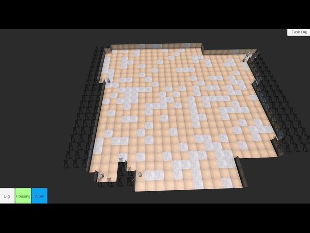
then on a camera you can tell it to render into that texture instead of the screen
Does that mean I'd need 1 camera per car displayed?
it could it depends on your needs
are the cars static, do they change in any way?
Yes
so yes they change or yes they are static?
Their color change dynamicly
while they are in icon form?
Yes
yeah so would need 1 render texture and 1 camera per
if they were static you could do it with 1 of each, then just create regular textures at runtime to use later
I got another idea, as they are rendered with an orthographic camera, can't I use 1 camera to get the texture for them all?
that is possible as well
to use them in the UI you will need the RawImage component instead of a regular image componet
it has UV rect so even if you rendered them into 1 texture, its still easy to have different UI compnents only show 1 part of the texture
if that makes sense?
that should make aligning it in the UI easier, 1 texture with all cars, but 1 RawImage component for each car you want to display in the UI with different UVRect settings
can use layers and culling settings, to have the camera capturing it only see the cars you want and not other thigns in the scene
i wanted to do that actually!
i just dont know how to lmao
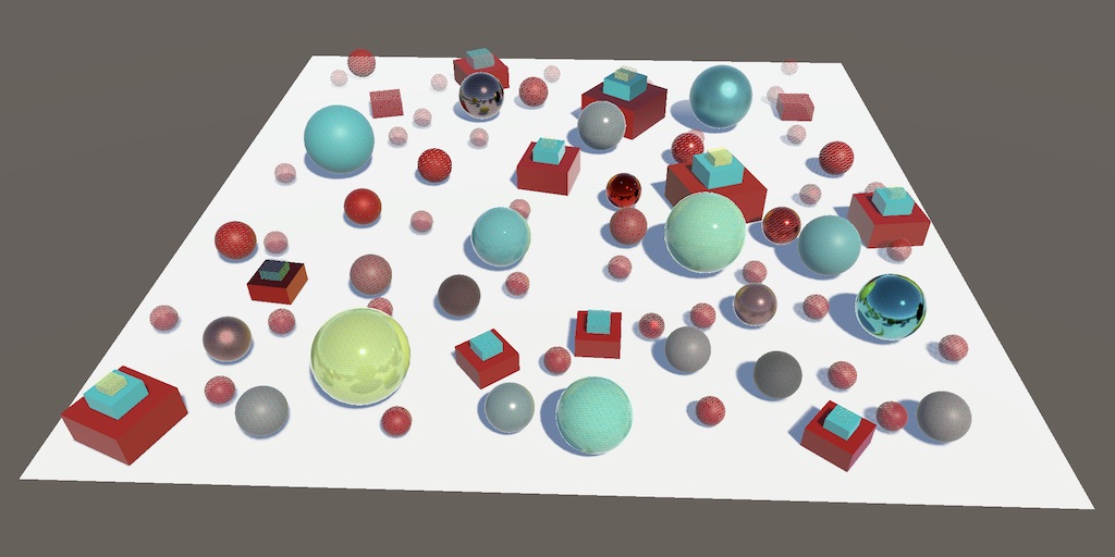
i dont have unity open right now, but iirc there is a node called SphereMask
you tell it where the center is, then you feed in the world coords as well
then you can adjust the radious
I was thinking of making it so like an explosion happens when the scythe gets smashed down
well shit you got me curious now lmao
its 2 am
i dont get how you'd do that though
oh
something like this going into your lerp
for time?

well to use time one sec

ignore the errors i dont have it all hooked up
max radius you would just have to figure out what value you need
same for Center since 0, 0, 0 would be center of the map, so you would want to set that to where teh center of where the effect should be
but with this you could adjust combattime and the effect would spread from 1 point outwards
I just feel like venting for a quick second, but... God, I think the thing I hate the absolute most in Unity out of everything is how much it anti-supports letting people access and control lighting data in custom shadergraph shaders.
I've been fighting with making a Toon Shader for so long, and it feels so annoying, because all the lighting data is right there, it's not not possible for me to easily modify it using stuff like ramps and color modification.
Is there ANY solution in 2024, when all I want is a node that outputs the full suite of URP lighting, as if an object were lit, but ALSO allows me to modify that output for stuff like Toon Shading and Lighting Ramps?
what do I hook the sphere mask into tho? @strange basalt
you can just write hlsl as you need, but yes 100% i wish it would let people write there own master nodes, then use shader graph to drive the inputs to it
wouldnt i need to multiply or smth?
the lerp that goes between your textures and flat version of things, to its t input
tbh, I don't consider "just write hlsl" to be an answer either. with how godawful Visual Studio's hlsl support is, and how bad the documentation for Unity's hlsl implementation is, it's nearly impossible to figure out ANYTHING about it. Even ignoring how much of the documentation you can easily find is literally outdated or does not work.
My best attempts at doing things in HLSL literally just ended with me asking ChatGPT to write it, after I went through multiple websites worth of information where literally none of it works.
doesnt quite look right @strange basalt
to each there own, i would not want to might my own lighting model in shadergraph even if it did let me do it. but see lots of benefit of desing my own master node with my stylized shading then having shader graph as a artists friendly way to play with it
nvm me stupid
i also want to have a transparent sphere which shows how its happening
cant really do that in the shader, so would just have that as a seperate effect
a sphere with its own shader scaling up
yea thats what im doing
@strange basalt
good job, is coming along
most good effects are like this, really takes multiple things comiong togeather to make it
ill give the sphere some distortion effect to really sell it
add some noise to it to make it less boring
bit of screen shake, or messing with the camera FOV too
something did get fucked up with my materials tho
there is screen shake for the scythe slam
@strange basalt
this is what the gameplay looks like...kinda... lots to improve on
compression killed the vid
still looks pretty cool already
I need to work on a lot of camera shit
its killing the game pretty hard
plus I need to learn how to make actual shaders
and not just these random effects
camera is one of the harder things to polish
it will come with time, like programming doing shader is very much just trying to break down a problem as much as possible
and seeing things you like elsewhere and trying to reason aobut how
lots of my systems are really badly written
and a lot of things that id love with projectile manipulation just isnt possible without rewriting a lot of things
plus theres DOTS which would be extremely useful for optimization
are you hitting the need for such optmizations though
it is a very different way to approach thigns and not as free form or prototyping friendly
my laptop has some issue where at a random time it decides to shit itself and cause every game to run below 10 fps
its not even just the game
but you can use a profiler to figure out what it is
I can run elden ring at 110 fps
but sometimes it gets so bad that a built empty scene runs at 40 fps
yeah something sounds pretty off there if a empty scene is doing 40fps
is this just in editor frame rate?
no, I built an empty scene
editor has a lot of overhead compared to a build
does it effect non unity things?
I just don't know how to go about restarting from scratch
or perhaps the same drops on other unity games
yeah
ah so something weird on the system maybe thermal throttling
elden ring drops down to 5 fps
not thermal throttling
the cpu is cold
sometimes it starts burning my hands and it still runs at perfect fps
feels like I have a fucking crypto miner on my pc
would it be possible to get the (probably wording this wrong) "light data" from like spotlights n' stuff
cuz i have an unlit shader and i wanna attempt to add support for lights like that
kinda dumb buuuuuuuuuuuuuuuuuuuuuuuuuuuuuuuuuut
Hey there! In shadergraph, you see a standard chroma key result on a video render texture using a Color Mask node. note the pure green mask color selected in the inspector.
In the 2nd image, note the high range value and that the avatar's eys and hair contain colors no where near the desired mask color, yet those are turning transparent while there is still a green edge in the resulting image. Something wrong with the Color mask Range calculations if the green is still in there at the range value shown.
What gives? Do I need to pipe this through multiple color masks so I can chose multiple shades of green?


Hiya - I'm trying to put a renderMesh on a quad in my 2d game. So far I:
- Have a 3d camera that outputs the rendermesh
- Created a material out of the renderMesh
- Have a quad in the scene
- Assigned the material to the quad
- Lit the scene
The result is a material that looks good in the inspector - I can see the character.
The quad is completely transparent, though - I see nothing.
When I add "Lit" as a second material to the quad, I can see the character, but the whole quad takes on the background color of the camera (even though the camera background is set to 0 alpha)
I think from some googling that I need to edit the shader (which happens to be Sprite-Lit-Default) to support the alpha from the camera? But I'm wayyyy out of my depth looking at this shader file
This: https://discussions.unity.com/t/render-texture-on-2d-sprite/677593/2 is a very brief pointer of what I want to do, but the person there leaves it at "*still need to use some transparent material shader i think"
nvm - figured it out through sheer luck by setting the shader to unlit-transparent-cutout
is there a way to not make the shader graph as bright? (left is shader material, right is skybox.)

this is the shader graph inside btw


yeah just multiply the last node with any float variable.
The shader graph you posted already has such a node but it is connected to emission instead of base color. (They are basically the same but emission ins't used here)
Does anyone know if subshader dropdowns behave like keywords?
I want to compile different code in hlsl based on which dropdown option is used but I don't see what refernce it uses.
Compute shader optimisation question. I know that if you have a compute shader where for each pixel you need to sample the 8 neighbouring pixels, then it is better to do those texture samples first (once for each pixel) and store them in group shared memory, add a barrier and then process them from the group shared memory.... is this also the same if it's not a texture, but a compute buffer? Is querying the array first and putting the values into group shared memory also worth it? Thanks.
Anyone know why a dither node is crapping out at certain resolutions / window sizes?
i have water shader which uses the depth buffer and ive set the shader to render both front and back faces. but for some reason the water depth visuals only works on one side of my plane mesh, why is this?
it looks like glass until i rotate it

shouldn't it work for both sides if i have both front and back face rendering on?
it works fine if i duplicate and 180 the mesh but i would rather not
maybe because the normal facing backward on the back face.
right but im not using the normal in my depth calculation
im using depth buffer to world position and fragment world position
calculating the difference and then converting to 0 and 1 range
unless the depth buffer itself uses the normals in a way i do not know about
let me just do a quick test with a grey output to see if thats what it is
well damn
its the depth buffer but i dont understand why
this has to be bug surely? i have front and back face rendering on and im putting scene depth straight into color output, why would it go black when i rotate the plane

could it be negative? try absoluting it
yeh tried - its still black
seems the values are 0
its as if they zero it out based on the mesh normal perhaps but thats an odd way to calculate depth
@tacit parceldont suppose you could try replicate to check ?this is the entire graph

if it doesn't happen for you then ive broken something lol
which is the last node and what do you mean by multiplying it? (im kind of new to these shader graph things)
is this how i do it or am i doing something wrong

im trying to make it the same as the skybox
i have also seen that it tints the sun and some clouds if they are bright enough.

Because your Game window has a non-uniform scale for previewing purposes
It has no adverse effect on anyone natively running your game at those resolutions
Yes that is the right setup. Now you can adjust the brightness via the the "emission tint" variable in the material inspector.
They ads probably tinted because the emission tinted color isn't pure white
Hello, i am trying to offset my vertices a little to achieve a sort of pulsating motion. What i want to achieve is that the object that the material is applied to kind of shrinks and grows very slightly. What i have right now is a sine wave time value multiplied by a factor and added to the vertex position. The object fully offsets in one direction which is not yet the desired result. I would like to know how i can get the direction from the center of the object to use it in the calculation and offset the vertices correctly

Get the normal of the vertex, multiply it by you offset and add to the position.
This seems good, do you know by any chance if there is a way to do it through the origin of the object? i think that might be even better for my usecase
basically move away from or towards the origin
Could try subtracting the vertex position from the object position and using that as the direction.
i'll see how that will look thanks
Or the other way around actually
Add 1 after Multiply, then Multiply with Position instead of Add
This happens because the faces are not connected right?

Yes, smooth shaded mesh wouldn't give gaps
Hello,
any ideas why this could be happening?
the first model is something from an asset, the second one is after importing the fbx to blender and then exporting it.
ALL model import settings are identical.
The first one has an outline, and the second doesn't, using unity's toon shader.

performance question for shadergraph. Is it expensive/bad-practice to use The Length node? I know in c# land doing those sqr root calculations is sometimes touted as a "no no" but not sure what kind of optimizations go on in shaderland. I didn't see a sqrDistance node or anything so is it "ok" to use Length?
I think it's about as expensive. If you can avoid it, it's better to do so. To calculate the square length of a vector, you just need to get the Dot product of it, where both inputs are the same vector.
Ok great to know thanks a lot!
aparently i was not exporting tangent space normals
Avoiding expensive calculations is always preferable when possible but GPUs are stupid fast. As an example, the SimpleNoise function does 6 pows, 12 sins and dozens of additions/multiplications for each sample. Even then many use those procedural nodes (often even many of them at the same time) in pixel shaders and it will be totally fine on modern PCs. If you target low end mobile devices or something like that, then micro-optimization might be fine but on modern PCs calling sqrt "no no" is really silly on C# side either. Use what you need, no more no less, try to optimize only in very specific situations
yeah I agree it's not always as big of a deal as people make it out to be on the C# side
It's usually not as big of deal. For example, when I need to do circular shapes in shaders, I don't even care if there's way to optimize it (because usually there's not really), using Length is totally fine. Redundant calculations should always be avoided but you would be surprised how capable GPUs are, there's no need to waste hours trying to avoid operations that won't really affect the performance anyway in the bigger picture
I am trying to recreate Physics based sky from this[1] git hub repo that is based on this[2] article. Repo is written in C++ and OpenGl. I rewritten all of the code to be HLSL and the problem is that my skybox just renders black. I tried tweaking some values and equations, but it had no effect. I am quite new to shaders, but I found topic of Physics based sky to be very interesting. I would like to hear any suggestions how to fix my shader.
[1] https://github.com/newpolaris/Atmospheric-Scattering/tree/3a3b96a136e9dd703ca037cfbca071749a183f1d
[2] https://www.scratchapixel.com/lessons/procedural-generation-virtual-worlds/simulating-sky/simulating-colors-of-the-sky.html
My shader code: https://pastebin.com/crNYR48X
Is it possible to use a custom mesh in place of the default Unity skybox sphere?
yo I want to make my toon shader cast toon shadows on other objects that have the same toon shader enabled, does anyone know how I can do that?
What Rendering Pipeline are you using? In URP you can make it so only objects on the same Rendering Layer will cast and receive to one another. These shadows are saved to a Shadowmap texture that each shader samples from based on its layer (if Shadow Layers is enabled), so you might be able to override the Layer used by the shader in the shader's Forward pass
As far as I know it's not possible. Is there a specific reason why you would need it?
Hi, can someone help me project a moon texture onto the skybox? I'm using a modified built-in procedural skybox
I'm trying to make it more like the one of the right, but it's the one on the left


OK, I did manage to do it, but there's something wrong. Whenever I go towards the edge of the, it does flattens the projection, see right. How can I fix this?
Here's how I calculated the UVs
half2 _moonUV = (((_WorldSpaceLightPos0.xyz - ray) / _MoonSize) * float2(-0.5, 0.5)) - float2(0.5, 0.5);


Also, this is how I did the texture: col += tex2D(_MoonDetail, _moonUV)
Hello guys, I have an error about the Shader Graph Package. I don't know how to fix this I tried to add this "com.unity.shadergraph": "14.0.11" to the manifest.json file but it's not working.

Did you actually install it via the package manager?

I wonder if it's a valid version. Try deleting it and installing the package again.
alright
Also, what unity version are you using?
2022.3.0
Hey dlich, can you help me please with this?
Maybe update to the latest 2022.3 as well.
In the shader graph change log they specify the unity min versions for some reason.
Whenever you go to the edge of what?
someone suggested me to change the Unity version
Like, when it's close to the x axis
I know it has to do with how the UV's on the skybox are
And what are all the variables in the calculation? There's a lot of context missing to be able to help you.
I'm using the built-in procedural skybox
I've just modified it to have the moon, clouds and stars
alright it's working

Well, that's a lot of changes. And it also implies I need to know how the built-in procedural skybox shader works, which I don't.@waxen grove
Oh
Maybe share the whole shader. I'm not sure I'll be able to help though.
Here's what I have so far, what you are looking for is on lines 436 (Drawing the moon) and line 376 (Calculating the UVs)
!code

Posting code
📃 Large Code Blocks
Use links to services like:
https://gdl.space/, https://paste.ofcode.org/, https://hatebin.com/, https://paste.myst.rs/, https://hastebin.com/
📃 Inline Code
Surround code with three backquotes. Not quotation marks.
To format as C#, add cs to the first line:
```cs
// Your code here
```
Add a comment with a line number if there is an error message.
Also, can you share a link to the original shader?
Here's the original link (It is literally just a modified version of the default skybox)

GitHub
Unity Built in Shaders. Contribute to TwoTailsGames/Unity-Built-in-Shaders development by creating an account on GitHub.
Also, I can't do the code blocks because the script is too long
Here's a more generalized view about my problem- See where it collapses on itself? I want to avoid that when the sun is facing that direction

I've read the original shader a bit, but it doesn't make sense to me. I don't think I would be able to comprehend it without spending a considerable amount of time reading though it and testing.
Perhaps someone else would be able to help you. Just share your shader correctly.
I would, but I literally can't... it's too big to fit the whole shader, and I've already included the parts that do matter
I mean share it via paste site. Or upload to GitHub or something.
!code
Posting code
📃 Large Code Blocks
Use links to services like:
https://gdl.space/, https://paste.ofcode.org/, https://hatebin.com/, https://paste.myst.rs/, https://hastebin.com/
📃 Inline Code
Surround code with three backquotes. Not quotation marks.
To format as C#, add cs to the first line:
```cs
// Your code here
```
Add a comment with a line number if there is an error message.
Oh, I see I see
🤦 I idio
https://hastebin.com/share/ejarotokib.cpp
Here you go
Hastebin is a free web-based pastebin service for storing and sharing text and code snippets with anyone. Get started now.
Guys, I'm following this tutorial https://youtu.be/_RbxRYAWl3g?si=OQgn74ylAzgJkvDU and I installed the HDRP Package. But when I create the Sky and Fog Volume the inspector is not the same as the video, I mean the Component is not the same so I can't follow the video check on 0:46

simple tutoriel: How to add custom skybox to your scene.
it was a light gray and i changed it to white, but it still doesnt seem the same. its fixed the weird yellow bit, yet its made it more bright.

(shader graph) I'm getting a significant performance hit when using a sample texture 2d LOD in the vertex shader on mobile, there's also no performance difference between using 1 or 3 sampler nodes, it's just "on or off", anyone knows how to avoid that except not use texture samplers?
How large is the texture? My wild guess would be that it might have to do with the memory overhead and not the performance if the sample count doesn’t even matter
It's just 64x64
Nvm then
Hey is there any good unity shader graph tutorials?
Hey, how can I make a shader that ignores mip maps for a texture?
Here's the base for the shader: https://github.com/TwoTailsGames/Unity-Built-in-Shaders/blob/master/DefaultResourcesExtra/Standard.shader
Hi, very beginner question, I'm trying to find sprite-lit-default but I can't see it, does anyone know how to?

That sounds like a shader and not a material. Create a new material, and add the sprite-lit-default shader to it. (I don't know much about 2d)
Ok I fixed it... it was just that I didnt make the proyect an universal, I got confused with the name, then I installed an Universal 2d pack on the pack manager and fix it (just in case someone has this problem)
You'll need to modify the fragment/pixel shader to always sample the desired mip level(i.e. 0 which is the same as the original texture).
Or just disable mipmaps generation for the texture.
Ok thanks, I'll try to do that
I still want it to have mipmaps when used in other places so I'll take the first option
Might be easier to have 2 texture variants then. One with mipmaps and one without. It's a bit of an overkill to modify a shader just for that.
Had a typo in the message that made it sound ambiguous, so check it again to make sure you got it right.
I understood it right, no worry. Thanks
Is there a way to make a billboard shader ignore certain rotation axis of the camera?
I'm trying a non-volumetric cloud solution and it works okay, I just want the billboards to ignore the camera's z rotation so the clouds don't rapidly rotate when the aircraft spins
https://cdn.discordapp.com/attachments/288230143686606858/1276773105792188516/image.png?ex=66cabf1d&is=66c96d9d&hm=154f5de144c9830e51279fbe9ff1761d3ef6d45e4ec65968b9a06de26ad4b7c0& setting it to a lit shader also doesn't seem to be working right :/

(the white clouds are just default lit shader, the blue ones are the billboard. The color should be the same)

How do I pass vertex data to this shadergraph?


My code
it gets position and normal right
but materialType doesn't get correct
I know shader graph, but I'm not a C# guy. Still I'll attempt to help 😅 If you're trying to pass something to the shader graph through a script, you can expose parameters in the graph and change them with the script.
Thanks for the attempt!
I can expose stuff such as setting textures and so on. I need to pass per vertex data
What kind of per vertex data do you need to pass?
Afaik shadergraph generates specific vertex inputs (position, normal, tangent, texcoords should all work fine) - but doesn't expect blendweights. If unused, you could use texcoord1 though. Which you'd obtain in graph using UV node (no need for custom interpolators either)
Alternatively could try passing an array/buffer to the material, which you could then index with the VertexID
I would honestly just prefer to pass array of vertex data instead
I tried texcoord1 and as well attempting to just use texcoord0 with 3 dimensions to fit the size of vertex
it just doesn't work
I don't know what's wrong
I feel like this structure is meant for script based shader coding

I literally cannot find any resources on passing data for "Custom Interpolator Node"
It should work in both cases, but you don't need to do anything in the graph to support it - don't add a custom interpolator. Just use the UV node as you would usually - shader graph handles passing it between vertex and fragment stages for you behind the scenes.

So this is the new layout as you suggested
it still doesn't work all UV and MaterialType becomes 1

when I populate per vertex data I set these to 0 to see if 0 gets passed

this is rendering UV part as color and as you can see it is all yellow
which means, 0 was never passed
Are you using the UV node or your custom interpolator still?

I'm not sure why you're using custom interpolators at all. Are you trying to have "Material Type" driving something in your shader?
I dont think I am using custom interpolator
Remove them and just try using the UV node in the fragment stage. I don't know how to make this any clearer
I think the way I am trying to use the custom interpolation is inorrect
Aren't the two custom things there called "custom interpolators"?

Custom interpolators are for calculating something in the vertex stage and passing to the fragment. They are not for passing data from the mesh
and I dont think this is how you pass data to custom interpolators
I want per vertex data to be passed not per mesh


yes
let me change the values as well
to see if I can pass actual numbers

Commented out the 0s

yes it has been passed
Nice. To access the materialType in shader you'd use another UV node but set the channel to "UV1" instead of "UV0". Can use Split (R output) or Swizzle (with "r" or "x" in field) nodes to convert down to a float

how do i do something like this in unity

Hey, is there any way I can add a noise map that controls the alpha of a texture using a shader and make it so that if alpha is already 0, it stays at 0? I'd like to make my tags on the road feels like they're not freshly painted

I was hoping to find someone decent with the shader graph to help me mask a grid shader/ EX Show the grid around an object/mouse then dfade as it gets further from the object
A cylindrical mesh + a transparent material + a texture that has alpha fading towards the edges.🤷♂️
Store the noise in a separate texture and multiply it with the original color output.
Hi guys,
Does someone know how can set render targets, what are the steps? I have 3 render targets to set. See more in thread
Shader falls back to default/diffuse
Hello everyone! Could you please advise me on how to remove the seam in a shader? The shader isn't a pattern, so I need to somehow blend it, but I'm not quite sure how. The object is a cylinder, I've tried different UV unwrappings but came to the conclusion that it's a shader seam. I followed a YouTube tutorial to create this shader, so I'm not sure how to hide this joint. Thank you in advance.

Use a texture property with the reference _MainTex
is there a way to extract the camera position and rotation from a model view matrix or a projection matrix?
One method would be to use a "seamless noise texture" rather than the procedural noise nodes, and an integer tiling value. (Also assuming the cylinder mesh takes up the full 0-1 x axis on the UVs)
May be able to find one online or search for a method of generating one yourself
I have a quick question, I am using Instanced meshes, but if I bake lighting they are not included in the light built, do I need a special shader which also works for instanced meshes?
_WorldSpaceCameraPos should give you the camera pos. I think UNITY_MATRIX_I_V._m03_m13_m23 might also be the same.
As for "rotation", that isn't as useful in shaders, you'd usually just use the matrix to apply the transformation instead of extracting that
no like im just curious is there a way
I'm stupid

why does this not work
I copied the texture blend section of the polybrush shader of the albedo
I'm trying to make one for normals but idk what I'm doing
Hello, I am very inept when it comes to shader graph in Unity, and I was wondering how I would go about making this laser shader have a waving effect. I'm sure it's something simple to modify the UV and use Time node but I just can't get it to work... 😅

I keep getting this error:
Shader error in 'Custom/CubeShader': unrecognized identifier 'VaryingsMeshToPS' at (HDRP)/Library/PackageCache/com.unity.render-pipelines.high-definition@14.0.10/Runtime/RenderPipeline/ShaderPass/VertMesh.hlsl(3) (on d3d11)
Compiling Subshader: 0, Pass: ForwardLit, Fragment program with <no keywords>
Platform defines: SHADER_API_DESKTOP UNITY_ENABLE_DETAIL_NORMALMAP UNITY_ENABLE_REFLECTION_BUFFERS UNITY_LIGHTMAP_FULL_HDR UNITY_LIGHT_PROBE_PROXY_VOLUME UNITY_PBS_USE_BRDF1 UNITY_SPECCUBE_BLENDING UNITY_SPECCUBE_BOX_PROJECTION UNITY_USE_DITHER_MASK_FOR_ALPHABLENDED_SHADOWS
Disabled keywords: SHADER_API_GLES30 UNITY_ASTC_NORMALMAP_ENCODING UNITY_COLORSPACE_GAMMA UNITY_FRAMEBUFFER_FETCH_AVAILABLE UNITY_HALF_PRECISION_FRAGMENT_SHADER_REGISTERS UNITY_HARDWARE_TIER1 UNITY_HARDWARE_TIER2 UNITY_HARDWARE_TIER3 UNITY_LIGHTMAP_DLDR_ENCODING UNITY_LIGHTMAP_RGBM_ENCODING UNITY_METAL_SHADOWS_USE_POINT_FILTERING UNITY_NO_DXT5nm UNITY_NO_FULL_STANDARD_SHADER UNITY_NO_SCREENSPACE_SHADOWS UNITY_PBS_USE_BRDF2 UNITY_PBS_USE_BRDF3 UNITY_PRETRANSFORM_TO_DISPLAY_ORIENTATION UNITY_UNIFIED_SHADER_PRECISION_MODEL UNITY_VIRTUAL_TEXTURING
Here is my shader: https://gdl.space/anenupekov.cs
HDRP btw
hook Time into a Sine function and add it to UV's y component
What do you mean by waving? Make it wiggly?
yes, wiggly, like a sine wave
tried this, but it just moves the whole thing up and down, not quite what i was looking for
Try inputting uv.x instead of time
Hello, i would like to scale my UV's back to the actual texture size in shader graph.
I am following a video where it says uv's are normalised between 0 and 1.
They use
data.uv * _MainTex_TexelSize.zw;
Do i just use the texture size node and put the texel width and texel height value into a vector4 to multiply or the regular width and height?
ah i just use a vector2
How do I include 2 colors in a normal map? For example, lets say I have a brick normal map, and I want the bricks to be red, but the crevixes to be black. How would I go about doing this?
normal map contains surface normal direction, it cant contains more color, let alone 2 colors...
but you can add 'color' information into normal alpha channel, and parse it anyway you like (example, alpha > 0 is red, else it's black)
or, maybe you use the blue channel, but then you'll need to parse normal data manually
Normally you would use a base texture aka albedo texture for the color.
You could also take inspiration of this blog post, where it packs normal + smoothness + color "gradient" in a single texture, that is then used to mixe between two constant colors : https://unity.com/fr/blog/engine-platform/experimenting-with-shader-graph-doing-more-with-less

Unity
You can improve the runtime efficiency of your shader without sacrificing the quality of your graphics by packing physically based rendering (PBR) material information into a single texture map and layering it into a compact shader. Check out this experiment.
idk if its a right channel but how do i use roughness maps in unity?
I know that i have to invert values cuz unity uses smoothness and not roughness, and then put it in alpha channel of metallness map, but i dont think it works for me, anyone can help me?
also im using urp
If you're not making custom shaders, ask in #archived-urp
If you are making custom shaders, show your work
Please remove any offensive content from your bio, for this server, thanks.
!mute 520992992899760198 If you want to be childish be my guest. When you decide to grow up, you can return and use this server.
 realotoko was muted.
can someone help me make this vert billboard ?
        void vert (inout appdata_full v, out Input o) {

            #if defined(PIXELSNAP_ON)
            v.vertex = UnityPixelSnap (v.vertex);
            #endif

            float4 color = v.color;

            // waving
            float factor = (1 - _ShakeDisplacement - color.r) * 0.5;
            const float _WindSpeed  = (_ShakeWindspeed  + color.g );
            const float _WaveScale = _ShakeDisplacement;
            const float4 _waveXSize = float4(0.048, 0.06, 0.24, 0.096);
            const float4 _waveZSize = float4 (0.024, .08, 0.08, 0.2);
            const float4 waveSpeed = float4 (1.2, 2, 1.6, 4.8);
            float4 _waveXmove = float4(0.024, 0.04, -0.12, 0.096);
            float4 _waveZmove = float4 (0.006, .02, -0.02, 0.1);

            float3 worldPos = mul(unity_ObjectToWorld, v.vertex).xyz;

            float4 waves;
            waves = worldPos.x * _waveXSize;
            waves += worldPos.z * _waveZSize;

            waves += _Time.x * (1 - _ShakeTime * 2 - v.color.b ) * waveSpeed *_WindSpeed;
            waves = frac (waves);
            float4 s, c;
            FastSinCos (waves, s,c);
            float waveAmount = v.texcoord.y * (color.a + _ShakeBending);
            s *= waveAmount;
            s *= normalize (waveSpeed);
            s = s * s;
            float fade = dot (s, 1.3);
            s = s * s;
            float3 waveMove = float3 (0,0,0);
            waveMove.x = dot (s, _waveXmove);
            waveMove.z = dot (s, _waveZmove);

            v.vertex.xyz -= mul(unity_WorldToObject, waveMove).xyz;

            UNITY_INITIALIZE_OUTPUT(Input, o);
        }
Thank you, it really helped, although the result is not what was expected, but it fits. And how to open shaders that are "outdated"? I found a good shader that I need, but it doesn't work in my version of unit, how to fix it? Instead of a shader, I have a pink color. https://github.com/JPBotelho/Soap-Bubble

GitHub
A surface shader based on ShaderX1. Contribute to JPBotelho/Soap-Bubble development by creating an account on GitHub.
If you have a new question please ask it to everyone rather than in a reply.
But surface shaders only work in Built-in RP. If working in other pipelines you would need to rewrite it manually, or find another example for your render pipeline.
Got it, thank you very much. I apologize for asking the question incorrectly.
What shader should I use for a game with shadows/pixel lights but no reflections and no PBR, just opaque materials with metalic and smoothness? I feel like standard shader has too many features that I don't use and that may be slowing down rendering a bit
Something like #1263105452112351232
"Metallic and smoothness" are what PBR is, basically
I meant no pbr texture
Whether it allows you to use a texture or not doesn't make a practical difference
URP has "simple lit" shader and BiRP has "mobile" shaders which are cheaper
Shader features you don't use on a material get compiled out of that shader variant and so won't cost performance, at least on SRPs
PBR shaders are somewhat more expensive even with the same setting than a traditional non-pbr specular shader, afaik
do you guys ever use SystemInfo.graphicsShaderLevel to determine if you can use a specific shader feature?
https://docs.unity3d.com/6000.0/Documentation/ScriptReference/SystemInfo-graphicsShaderLevel.html

turns out all my phones return graphicsShaderLevel 50 lol ... all 8 of em
Thanks
that's quite literally the peak for most phones, 6 and 6.5 are outside of the phone capabilities currently

what happened to my shader, why work like this(dividing screen in half) (i don't understand shaders in i watch video and make this because i want to try to make shader)


Check settings on the renderer feature used to apply the shader to the screen
Here ?

a and this shader is

ok i find problem in video author shows this work on blit but on my project when i switch to drawprocedural ad its works


Hello! I wanted to know if it's possible to create a fade effect in my shader using Shader Graph. I'm using a transparent material, and I think the issue might be related to alpha clipping. However, I've unchecked it in my Shader Graph, so I'm not really sure what's causing the problem. If anyone has a solution, I would really appreciate it! Thank you!

Here is my mask that i put in alpha !

Alpha clip cannot fade. Why is it on?
ok thank a lot , i don't know i deactivate it but i still have the entry on my shader

Hi all,
Just wondering if anyone had any ideas on how to achieve this kinda of effect with URP Shader Graph?
I can get the texture to 'scroll', but not 'evolve' like in the video.


You could use 3D noise and just change the z axis to make it "evolve"
Forgive the ignorance, but how do you use 3D Perlin noise in Shader Graph?
I don't know
Ah. lol.
https://github.com/JimmyCushnie/Noisy-Nodes
Just found this that I think has promise. 🙂
GitHub
Adds various noise generation nodes to Unity Shader Graph, including 3D noise nodes. - JimmyCushnie/Noisy-Nodes
lol. There's timing.
Yeah will do. Calling it a day for now, but will try it out tomorrow 🙂
Ok
Thanks a lot
!collab
:loudspeaker: Collaborating and Job Posting
We do not accept job or collab posts on Discord.
Please, use Discussions to promote yourself as job-seeking, advertise commercial job offers, or look for non-commercial projects to participate in:
• Collaboration & Jobs
Hello everyone somebody could help me? with line renderer component: i need make corners like this with line renderer

To draw a square you’ll need 4lines
Hello! Is it possible to sample a value in a shadergraph from c# code?
I would love to be able to pass in a vector2 and get an output from 0-1 on this node.
Currently it's doing displacement to a plane and a raycast to get the height of the geometry doesn't work
(Heading to a meeting, back in 30, many thanks for any help)

What are you trying to achieve? Is it about getting the modified physics data (transform height) from the raycast using the already displaced height of this terrain/plane?
I cannot tell from the wording if you want to move data from shader to script or from script to shader
Assuming from shader to script, it's not really practical
Commonly you'd rather run the same noise algorithms in a script just for that one point
Cheers guys,
@viscid knoll, kind of yes, I have rolling hills and I want to sample the height each frame at specific points. Traditional raycast doesn't work as it only hits a collider and I'd need to apply the mesh displacement to a MeshCollider.
I've assumed that the cheapest way to do this is to read from this point in the shader graph and then use that as an offset from the planes transfrom.position.y.
@grizzled bolt I was thinking shader to script, but if there's a way I can generate those combined gradient noise nodes in code and pass them into the shader, I'll have all the data I need to sample height in code.

The hills pan in a certain direction based on a UV offset passed into those Gradient Noise nodes, just not shown in the pic
It's not very practical or performant to get data from a shader graph to the cpu
Compute shaders are better at it but as I understand there's still a lot of situation where you'd rather have the scripts run their own noise generation anyway to prevent the hurdle of having to pass data between gpu and cpu
And it seems in your case if you do the deformation in a script, you might not to do it in a shader at all
That's an option yeah, I'd imagine that would be very performance heavy too though? Can't benefit from the power and parallelism of the gpu?
Documentation has the source code for all SG nodes, though just one gradient noise node is relatively expensive even on the GPU
you have to sample the texture data from your raycast hit (1 point), then abstract the offset that this 0-1 value represent on the y axis to add it to the raycast hit result, and get the final "computed" height on this point
You could not, but the CPU is capable of parallelism as well which would be useful in this kind of task
Yeah I thought this to, I may be wrong but my understanding is there is no "texture" here, it's all proc-gen'd data fed into vertex displacement. I can't do any kind of material.texture.GetColourAtPoint(vec2)
Indeed, the GPU would have to write the texture first and then the CPU would have to spend the effort reading it
I do not know if that's less or more efficient than doing it on the CPU to begin with
But it also depends on what kind of noise algorithm you use and if you utilize multithreading
Efficient terrain generation algorithms are kind of a big topic so there should be many options more efficient than gradient noise
Yeah
My current working solution is to have a camera with a fov of 0.01. In front of that camera is a tiny quad with an unlit shader that draws Linear01 depth buffer data. That camera renders to a 1x1 render texture and I sample 1 pixel. I get a value between 0-1 and I multiply by the cameras far clip plane. That gets me an accurate distance, but it's munches ~20-30 fps, and that's just one, I need ~10
I'd still think that a compute shader would beat CPU by a big margin.
Though, until you test and profile it's just an assumption.
Generate your height map in a compute shader then use it both in the shader for rendering and the CPU side as you wish
If you can reimplement the noise algorithm exactly on the CPU, then you can displace the mesh with the shader and then when you want to sample individual points on the CPU, just calculate the noise for just those points, no need to move everything over.
It also depends on how many points you need to sample
Generating the noise for 10 points in script is a different beast from doing it to every vertex
I read up on using a compute shader to do a raycast, but it required exporting the shadergraph to code and modifying that code. (The contents of that shader code was ~5000 lines and repeated itself 9 times, I'm not overly familiar with written shaders and didn't go further in this direction)
Interesting ideas, I'm not clued up on how to write that in a compute shader but I can give it a go 🙂
To use compute shaders you'll need to know how to write shaders and then how to write compute shaders as well
I mistakenly said compute shader in my comment because I thought that was what you were using, but my suggestion also applies if you're doing the displacement in a Shader Graph shader.
Are you thinking a hybrid solution, the shader does the displacement and the cpu, when sampling the height, runs the equivalent noise generation and then samples the value?
Yes
I like it, I could likely even do some optimisations by generating the noise for the current region, then instead of generating it every frame as it pans, cache it and sample the noise with the offset applied to the sampling point
https://github.com/Unity-Technologies/ShaderGraph/tree/master/com.unity.shadergraph/ShaderGraphLibrary
Am I in the right place for getting the source code to the Gradient Noise node?
https://docs.unity3d.com/Packages/com.unity.shadergraph@17.0/manual/Gradient-Noise-Node.html you can just look them up in the docs for the calculation
Awesome, thanks!
Hi. i need some help/guidance on a shader i need to make for a character. I have 3 skinned meshes. the third one is a blend of the 2 previous ones. Cause in the first object, parts have unwanted deformations. so i blend the proper deformations from object2. and the 3rd object has the final correct shape that benefits from physics sim and proper original skeletal anim.
so i explored many ways, compute (cant find how to update 3rd mesh's graphicsbuffer), manually set vertices (slow as hell).
I ended up using Vertex Shader in a shader file. in order to have the full features of standard shader, i started extracting bits of code from the downloadable builtin shaders. and ended up with a working test shader.
now that my vertex blending code works fine, i want to make the shader look good, so my question is do i have to modify all the passes and put my vertex logic in every single pass. Looks like there is deferred and forward stuff going on. i really have no idea what is what, its already a miracle if i managed to get to this point.
with the shader code, and the script i use to feed the meshes data.
i will apreciate if you can tell me how i can make all the shader work with that vertex blending code.
looks like i have to go through each pass and adapt.
camera has a lot of overhead, you could write a scriptablerenderpass in which you set up orthographic projection with cmd.setviewmatrix and cmd.setprojectionmatrix, set up the target texture with cmd.settarget and call cmd.drawmesh to draw the heightmapped thingy. then you can read back the data, or even better is to batch together a bunch of these into a 1*x sized texture that you will read back afterwards in one go
you could maybe even write the depth into a buffer too, that may be faster to read back but I'm not sure
use RenderDoc for debugging
@cosmic prairie interesting, sounds like it should optimise a lot. In my setup I have a lower poly version of the mesh which is displaced, no lighting, isolated via layermasks etc to try and optimise as much as possible
Shame we cant raycast polys without a collider...
Although I remember doing this in an old project, I had CAD data with ridiculous polycount, I used a grid of raycasts to pick up points on the mesh. There was no collider involved and yet the raycast hit the geometry. 🤔
I take it there's not an easy way to apply a vertex shader to everything in the scene with like a renderer feature? I was hoping to skew the whole world without applying it to every material
No, that's not possible.
I've followed the shadow example in https://docs.unity3d.com/Packages/com.unity.render-pipelines.universal@16.0/manual/use-built-in-shader-methods-shadows.html
In the end I'm left with the shadowAmount value. How do I use this in conjunction with my existing fragment shader? I'm trying to match the color with the Lit shader but I'm not quite getting there
This is usually the approach taken for ocean simulation
The GPU generates the height map for the entire ocean, and the CPU independently recomputes specific points to make objects float and whatnot
Ah of course, for simulating floating bouys on ocean surface!
For instance
unless you have an obscene number of objects, its better than sending data from the GPU, although that can be done asynchronously, with compute shader readback
but direct recomputation is much easier
and intuitive
In a script i am running lots of compute shader kernels. Each kernel modifies certain structured buffers for the next kernel to use, but this means that each compute shader is dependant on the last one to finish. How do i make sure the last one finished and do i even need to?
i’m pretty sure compute shaders dont execute in parallell
Hmm, weird. My issue might come from somewhere else then.
Basically when i started with unity i wanted to make a fluid simulation. Ended up making is 3d so i wanted a raymarching shader to visualize it, but it seems the data thats being sent to the shader is way different than what i get when i use GetData on the cpu and just visualize my voxel field with cubes.
could be lots of things, i dont know
Fair. imma keep on debugging, thanks for the help!
I did a bit of research and i think that compute shaders so run asynchronously from eachother, but dont wait for eachother to finish (which makes sense), so i need to either pause the mainthread and wait for the compute shader to finish or i need to combine every kernel into one
I know Unity's shadergraph by default has limitations regarding the types of blending methods, is there a way to get an overlay blending with it?
Or even through normal shader programming
ive gotten some very close results but they can have the side effect of really fading out whats behind it
really? mind sharing?
What if you use a command buffer, are they still run asynchronously?
from what i've gathered no, it does keep its order in the buffer, but it doesnt account for synchronization so compute shader execution might still overlap with one another. i eventually just opted to use fences, but this greatly reduced my performance. idrk what else to do
(URP) I am having an issue with transparency in build vs editor. The game I am working on loads a lot of assets from bundles in the cloud. One of these assets is a window. It is transparent in the editor when loaded (this loads from the cloud as well, the assets are not in the project at all). In the build it is not transparent.
The obvious solution is that its not including that shader variant. However I have both done a capture from the editor into a ShaderVariantCollection and added that collection to the list, but I have also added the shader to the always include list so it will build all variants. IT STILL IS NOT TRANSPARENT IN A BUILD. I'm not sure what to check next.
Using URP and the shader is custom built from shader graph
There shouldn't be any specific keyword needed to make it transparent. Have you tried making a development build and connecting the Frame Debugger to it to see the keywords and blend state used for the draw call?
no, thanks. That gives me a good avenue to continue testing with
Hey folks, im currently trying to implement a screen space reflection shader and i really cant figure out what i've done wrong at this point that this is the output i get (which changes with the camera pos) heres the code: https://pastebin.com/DGe1TPbw


Pastebin
Pastebin.com is the number one paste tool since 2002. Pastebin is a website where you can store text online for a set period of time.
for some reason, I can't find it online...
how can I add the tint feature to base maps via shadergraph
like with standard unity shaders
the concept should be the same, multiply the base map color with a tint color parameter
I usually make sure to make an extra lerp to factor in the alpha of the tint colour as well
Is there a way to disable filtering (set to Point) on a Simple Noise? I want to get pixelated noise, not smooth like this (I am using URP, if that does make any difference)

No, the noises are generated procedurally without any textures being involved so there's no filtering being applied either. If you need pixelated effect, you need to round the incoming UV coordinates
You can do UV node -> Posterize -> UV port on Simple Noise
Though using a pixellated noise texture might be cheaper
oh, thank you very much! ❤️
guys is there a way through a shader, we make somehow the edges of snow mesh blend with the plane of the ground to create smooth transition or is it not possible through shaders alone ?

is it possible to use shader graph functions in normal shaders if yes how
Most of the node library docs have generated code snippets you could copy
https://docs.unity3d.com/Packages/com.unity.shadergraph@17.0/manual/Node-Library.html
ye but where do i import SHADERGRAPH_SAMPLE_SCENE_COLOR from?

The result of that macro depends on the pipeline. In URP it would end up using the DeclareOpaqueTexture.hlsl include
In short, sampling _CameraOpaqueTexture global texture reference
ok thank you
Guys, can shaderLab code be grabbed during runtime in the format as it is in unity?
Unlikely. It's all precompiled to regular hlsl(or other shader code)+ some data structures on the CPU side and then compiled to binary.
hey, i'm trying to make a screen space reflection shader and i think i'm missing the last step to make it work so i do not really understand how to check if the ray that's being sent towards the reflectionDirection is intersecting with geometry i would guess that you would check if the depth at the rayUV point is less than the distance the ray has traveled from the camera (so the "new depth") but how would you check this would you convert the rayPosWS into rayPosClipSpace and check if the rayPosClipSpace is further away? here's the code: https://pastebin.com/R7QuhBuA
Pastebin
Pastebin.com is the number one paste tool since 2002. Pastebin is a website where you can store text online for a set period of time.
there was a thread about this in unity forum, but I forgot where, basically you need to get the ground height (worldpos.z) and the snow height (again, worldpos.z)
now the tricky one is you can't just get the ground mesh position from snow material.
But I think you can get the depth map using render texture with top down camera (by rendering depth map, excluding the snow using layer), then use the render texture as the ground height.
It wont be easy, but it can be done (I think it already is)
i will look into it
add {} at the end of the first property (after "=white")
Not sure why textures need this, but they do
Yeah it's a bit weird, only breaks with other properties
Hello! Apologies if this isn’t the right place.
Yesterday I was looking at Scanner Sombre and wanted to try and implement the Lidar Scanner myself. I did my own research and found that most people or tutorials online use VFX Graph which is perfect for that, but i want to just do it in shader code if possible.
I have the idea of creating a post process that renders the depth of what i see in a flashlight “cone”. Storing that in a render texture and passing that on to a compute shader where i read that RT with the depth info and calculating the world pos of that pixel (Obviously later on id have some noise to choose the pixel and not do every single one…).
Once thats figured out i use Graphics.DrawMeshInstancedProcedural to draw a mesh of a quad at its position in a C# script.
I know im over complicating myself but I just want to do it in shader code. Before I start i’d want to hear if this is a good idea or im going in the wrong direction.
Any advice is helpful. Thanks!
Is this that precompiled data what we can see in Renderdoc as well when we check the shader source option?
Depends. You can see a lot of things in Renderdoc.
Shader source yes, that's usually in the language that the graphics api support
Yeah, sounds fine.
What kind of meshes will u be rendering?
a bunch of tiny quads representing the points?
Pretty much yeah
It might be tricky to do the "scanning while moving" part
if youre just doing snapshots whenever the lidar is activated, thats pretty trivial
I was just gonna do snapshots, i did think about the moving thing being a little bit different but we’ll see when i get there and if i want to do that
I see the lidar in scanner sombre just shoots out rays instantaneously in random directions
so that seems easy enough
Yeah i did think oh i can do raycasts or some form or raytracing but i just want to see if i can do it all in shader code except for the computebuffer part that will be in c#
Render the depth, generate random pixel locations, dispatch a compute shader to calculate all the hit positions, generate quads.
Alright well, i’ll give it a try! Thanks for the input, just wanted to make sure i wasnt going in the wrong direction
Yeah, I wouldn't use ray tracing for this, just stick with the depth buffer
Though ray casting would be fine if youre not shooting obscene amounts of rays each frame
good luck
hello Im trying to sample the skybox in shader like the code in the screenshot. But it is not correct in the editor, and when I check the framedebugger I see a grey result for the skybox
This is using a Custom RP based on this tutorial series by CatlikeCoding


A Unity Custom SRP tutorial about supporting level-of-detail and simple reflections.
Okay, does anybody know why this operation isn't just drawing the main screen? I assumed that blitting back and forth would be identical to perform no blit at all, but for some reason it draws an empty scene as opposed to when nothing is performed and it draws the objects in the scene properly.

To illustrate, empty scene is with the code present. Scene with cube in the middle is with code commented out.


Have you tried injecting your own command buffer into the render loop instead of using the Graphics class?
I have not. I was just trying to debug some strange behavior in my script by checking the texture contents with blit when I found this oddity
I'm just not sure the camera target is bound to the after post process texture outside the render loop.
I tried printing out Camera.main.targetTexture, and it doesn't come back as null
Maybe that's the problem 
The weirdest part to me is I have a similar piece of code in a different project that works just fine. This is all in OnRenderObject by the way

random thought came into my mind and got me wondering, when are compute shaders a usecase? they intrigue me but I have no clue when they should be used
For me, I'm using it for parallelized fluid simulation. While the rendering can be done through shaders, the actual math behind each particle's simulated forces can't be (as far as I know). ...I'm also using it for the rendering because figuring out Unity instancing in shaders is a terrible labyrinth that I don't want to figure out. But now I'm in this bind.
So basically, parallelized physics calculations I guess
When you want to utilize GPU cores in calculations outside of shaders
Simulations and generators are common uses, but the applications are endless
so like pathfinding?
or fluid sims
stuff that does a lot of math for many elements?
not sure what you mean by using it for rendering 
Yes
I'm passing the RenderTexture texture to my compute shader to perform pixel-wise operations manually. There are a lot of ways to render fluids, and one of them is through screenspace operations.
So instead of having a regular fragment/vertex/surface shader, I'm manually calculaitng the RGB at each pixel on the screen based on input RenderTextures and bunch of other junk
oooh that sounds interesting
I'm guessing this fluid sim is for water? so ur doing like reflections and refractions?
It can approximate fluid-like behavior, depending on the parameters, but yes I'm trying to simulate water. While reflecting and refracting is a part of it, a major portion is actually performing smoothing operations on a depth image of the water particles to approximate surface of a fluid. There's a million academic papers out there on this stuff with tons of differnet implementation methods, but I'm just trying to get this thing done rather than optimal
There's also like 3 major methods for fluid simulation where each have tons of depth in their own right.
The one I'm using is called "Smoothed Particle Hydrodynamics", but that's enough procrastinating. I need to figure out how to fix this thing 
 u got this
Blit just performs a draw call with texture A being passed as a main texture and texture B being the render target. There's no point in using it with either one of them being null.
Null corresponds to the screen RenderTexture is what I have been lead to believe
Is that incorrect?
I can't see anything like that in the docs. It seems you can blit back to the screen if you set both to null.
Ah, no. If source is not null, but target is null
This also

It's been a right pain in the posterior having to deal with the weird null exceptions because of it too :/
Yes, that's what I said. If the destination is null, but the source is not.
Either way, it didn't change the outcome even when I swapped to using Camera.main.activeTexture/Camera.main.targetTexture.
I don't think that would work as it sounds like you're rendering the render target to itself.
I'm not sure what unity does under the hood, but in most graphics APIs a texture can only be either in read/write state or render target state at the same time.
I'm not really sure what you're trying to achieve anyway
So I wouldn't be able to pass the active renderTexture to my compute shader?
If you just need to have the screen pixels in a compute shader, just set one of the cameras to render to a render texture and bind it to your compute shader. I don't see why you'd need to use blit.
I was hoping to avoid adding a third camera as I'm already encountering issues with the secondary one I have right now 
What does the second camera do?
It renders only the particles for my fluid simulation, so that I can use the depth image for post-processing.
And what kind of issues are you talking about?
Ah, apologies. I misunderstood. It's unfortunately not something I believe this discord would be equipped to solve. I'm attempting to develop a plugin for a third party vtubing software, and currently when I put the plugin into the software and kick everything off, my secondary camera seems to somehow kind-of commandeer the vtubing software's main camera status and erases all the GUI components of it.
It's one of the many things I was attempting to solve tonight, but it has yet to bear fruit.
Does the second camera render to a render texture?
Or the screen?
Render texture
Hmmm... In this case it's weird that it has any effect on ui or anything else really
Though I suspect there is some funky stuff going on with the copyFrom function I use to mimic the mian camera. Was going to test a bunch of things but many things broke and I tried catching 15 rabbits at once
Hey, I have a basic tilemap which looks like this.
I want to make the transition between colors smoother with some noise applied on the transition. How can I approach this?

Shaders do not have information about what's around each pixel, so generally you cannot do blends like this
You'd instead probably want to have a rule tile that represents a transition gradient between two textures and use that to blend textures that the shader already knows about
alright, thanks. I will see what I can do
How can we measure the performance of a custom shader? I have 2 shaders that achieve similar results, I would like to see which one is more performant.
If you want to measure specifically the fragment shader part of it, the simplest way is to fill the screen with that shader, by placing a quad/plane in front of the camera, and then swapping it back and forth while measure GPU time in the profiler.
Hey I'm new to unity and following Gabriel's tutorial on lighting shader graph but for some reason it isn't animated here is a comparison to show what I mean:
I added the time value and even tried setting the distortion speed higher but it doesn't work
any suggestions?
How i can make my own hdri shader
I want to make the visor have a fake reflectivity, like a env ball, but i want it to be black since it feels weird when its in another color

A cube map shader i mean
Nvm i figured it myself
Theres any shader that give a cool glass effect? Because the ones i tested or give a plastic look or loads a random sky box, that idk how to change

I will try using mtoon vrm to test it
You could render tile ids into a screenspace id render texture, then generate 1 pixel width outlines with a sobel filter, then generate an SDF texture with JFA. That gives you the distance to the edge. You can then sample that distance from the tile shader, normalize it and use it as a noise strength value. You need to sample the distance texture from your tile shader and multiply the noise value by (1 - normalizedDistanceToEdge). You can then output the resulting value as the alpha or shift uvs. Note that you have to keep the base tile layer without the noise and put noisy tiles on top or else you'll see holes in the world.
I hope you know graphics programming, otherwise it's easier to just draw some extra diagonal tiles and apply a global worldspace noise to uvs of all tiles with a shader 🙂
Hey sorry for bothering you but mind if you can help me out?
Nope, I know almost nothing about graphics programming. But its not a problem :) New challange
I'd go with the latter of my suggestions tbh, way less r&d.
Any reasonable way anyone knows I can add a component to my render pipeline to discard front faces behind back faces? I would like to discard the red highlighted area but show the green outlined area, in this example.
I can think of a couple ways to write this in a shader for a material that attaches to the object, but I'm not sure about a way that applies to all objects regardless of the material on it.

I can imagine maybe inverting the mesh in a render pass and drawing the background color over the new front faces, but I would like to be able to overlay this over another camera and I don't believe this would work
Some way to get backfaces to write to the depth buffer globally maybe?
I have this shader graph, i made this toon shader, but im kind of new so i dont know how to add a normal map input to this?

Sample the normal map with Sample Texture 2D node set to Normal mode. Use Transform node to convert from Tangent to World space, replace Normal Vector node in the Cel Shading group with that result
thank you!
Sanity check - If you need to do multiple passes with the same compute shader, can you use the same instance and just change the inputs between Dispatch() calls? I assume that's true... that the Dispatch call sends off that particular invocation of it with all the settings. Also, given the passes read/write from the same textures, I assume Unity makes that safe, i.e. 2nd pass doesn't start until 1st is complete?
is there anyway to add #include example.hlsl in the shadergraph? i know how to add #define by using keyword -> boolean/enum, but i dont know how to add custom #include
Can use Custom Function node (File mode)
ohhh, looks like i overcomplicated it, thanks for the insight 💡
Hey, I have a question, maybe someone will know the answer. I followed a tutorial to create a shader graph that creates a puddle like the one in the screenshot. However, I just noticed that the floor texture is scaling along with the water texture, and they don't match at all. Rescaling the puddle causes the issue where water is almost invisible. Is there a way to remove the floor texture's border and just keep the puddle?


I tried adding a regular transparent texture, but the area around the puddle turned black
Hey thats a long thing to tell and in that case i would say get the sample shaders from unity it includes puddles,ice,decal and more.
How to get:
Go to packages then shader graphs then navigate to sample and scroll down and then import production ready shaders.
Note: this is available in version 2022.3.35f1 or higher.
this might be a dumb question, but am i able to animate shaders graphs to happen on an event, or do i need to code the shader and do it from there? for example, a disolve shader happening on death or teleport or something,,, or would this be better done with a vfx
The simplest way is to have an exposed float parameter in the shader, then control that value from C#
material.SetFloat
i see isee okay thank you
VFX graph can be good for this kinda stuff too, just depends on how complex you need it
Like if you need it to dissolve into particles or something
yeah i was just thinking about that, i think it may just be better done with a vfx,, im just better at shader lol 
Has anyone gotten soft shadows (incl quality tiers) working in Unity 6?
I got a good system for 2022LTS but it completely breaks in 6, while the generated keywords are the same as the Simple Lit shader
why is any of this happening, the normal map isnt doing anything crazy like this

Is it fixed if you remove the normal map?
yes it is, but the map looks fine i think, i redone it multiple time so i really dont knwo whats wrong with it
The normal map icon is very small so hard to see but the colours don't really look as I'd expect. To clarify, Unity uses tangent-space normal map (the blue/purple looking ones) not object space.
Make sure you import the texture as the Normal Map type too
that must be the issue, am i not able to use object space maps at all?
I think you can with a custom shader but I'd recommend just baking tangent space ones if you can
alright thank you
Just to clarify, you do import the texture as a normal map, right?
I rebaked it as the tangent space and it looks fine, I normally just drag it in from my files and then after putting it in the normal map spot in the material inspector hit the “fix it” button from the “this isn’t considered a normal map” 💀 is that bad
I guess that does the same thing. In the past, unity wouldn't show you that warning, so you had to make sure yourself.
But it's always good to have a look at the asset import settings before using it. There are a lot of settings you might want to tweak.
Alright thank you!
Are there any shaders that have specular setups that are very similar to Unreal Engine 3 and alot of other old engines' specular shaders? Unity's own specular shader looks extremely odd, the specular map shows all over the model and is way more visible than it should be.

The only difference I see is brightness 🤔
Well here's the specular map, in UE3 the specular map is only supposed to show a little bit even if the scene is bright or dim. In Unity, the specular map shows 100% and in general makes my material look ugly

Not sure if that entirely makes sense with the way I explained it
This doesn't look like a specular map to me. Looks like albedo/color texture.
This is the color map

A specular map just decides how reflective the pixel is where it is sampled.
At least in unity.
If it means something more in unreal, you'll need to find the alternative in unity.
I guess it also depends on what kind of shader you're using.
Both unreal and unity has switched to pbr, where you dont manually define specularity anymore.
But you can use the legacy shader family which has bumped specular shader.. iirc, the specularity is on alpha channel
Alrighty, thanks for the help anyway
Hi all, I'm writing a custom shader which is called through the Graphics.RenderPrimatives function, in this I am trying to implement occlusion culling. That said I seem to be running in to a bit of an error https://youtu.be/G9L6SRxFJls (shown in this video). The code I am using to do this is below, to explain I am using the _CameraDepthTexture sampler from UnityCG.cginc and then comparing it to the active depth of the fragment being sampled. This seems to potentially work fine when the camera is still but moving it causes huge artefacts.
const float2 screenSpaceUV = i.screenSpace.xy / i.screenSpace.w;
const float sampledDepth = SAMPLE_DEPTH_TEXTURE(_CameraDepthTexture, screenSpaceUV);
const float depthBias = 0.1;
if (i.depth + depthBias < sampledDepth)
{
    discard;
}

return i.color;
I am definatly doing something wrong here, so if anyone knows a potential cause for this I would really appriciate the help!
This might be because your depth texture is being copied after your shaders fragment pass is processed. The active depth exists on a depth buffer, to make sure you have a thread safe copy to read it’s copied at some point to _CameraDepthTexture. In URP you can set when this is copied in your renderer asset. Idk about built-in though.
If you want this shader to cull geometry also using this shader behind it you need to define a custom depth pass so you can first write the minimum depth to the buffer then cull the geometry behind it in the lighting pass
When you stay still what I assume is happening is that it’s reading the depth from the previous frame which is why it looks ok. I’m not sure though because usually built-in depth texture is cleared between frames
In the built in render pipeline, the internal deferred shader uses a PBS lighting model. Is it possible for me to make my simple toon shader compatible with Unity's deferred rendering even though its not a PBS model? Or would I have to swap out the internal shader with my own solution?
Toon shading isn't really possible with deferred rendering, because of how each light is added additively on top of each other, so they can't be posterized together.
Unless you render the lighting to an offscreen buffer and do the posterizing on that, I guess.
But I don't think built-in's deferred rendering is customizable to that degree.
if you use URP or HDRP it is possible to edit the package to make it do the toon effect
built-in is outdated, don't use built-in in 2024 unless you know what you are doing and why you are doing it
Ah thank you! I'll look into this, I am using URP so I'll see if I can find what needs to be changed in their!
(Sorry also for the late reply, I ended up falling asleep xD) (It was quite late where I am when I asked the question)
Changing the value to force prepass seems to have fixed the movement issue! I have noticed though that my eyeballing on the two depth values wasn't actually correct. I've taken the differences between the two depths which should be black (if they where the same, but its clear that this isn't the case.) I'll look into this now, thank you for your help!
Okay take it back, the issue with the difference was that the new output of the prepass gives a completely black value. so the difference is always just the depth value of the actual pixel. Moving it back to the AfterOpaques, gives me back the black transparency (which is correct, but this then also has the issue of bringing back the movement issues again).
I am currently calculating the depth using this code:
const float dotValue = dot(wNormal, normalize(_CameraWorldPosition.xyz - worldPosition.xyz));
float4 clipPosition = UnityWorldToClipPos(worldPosition);
o.depth = clipPosition.z / clipPosition.w;
Potentially the distance to the camera is what is failing. I am passing in the position of the camera right now in late update, is their a chance that this could be the cause? And if so, where in the excecution cycle should the code sit for uploading data from RenderPrimatives?
I did a few more tests with this, and it seems the the depth buffer is slightly behind of the cameras real position

This was taken my just screen shooting the game as I span the camera around, its pretty clear with the opening of the "cave" that it is being mirrored to some degree.
So I think the assumption that the depth texture sample is somehow lagging behind on the sampling.
Right now the depth texture is being taken after trans parents this could be that the pass is using the last frames depth test

Sampling the prepass depth however just gives a black value (so zeri in everything)

Do shaders only work on UI objects that are in world space?
@vestal hinge
Ok a few things: the reason a render texture is black could be for two reasons. 1 it’s copied at a later stage then when you are readin it or 2 there is nothing writing to it.
When you force a prepass for a normal shader, Unity would first look for a depth pass on your shader, and will use your default lighting pass if nothing is found(I think). This creates two commands to render the mesh(one for depth, another for color) at two seperate render stages. This becomes a lot more complicated with renderprimitives.
When you call render primitives the shader is not run immediately, but the command is queued in the pipeline at the specific render priority https://docs.unity3d.com/ScriptReference/RenderParams-rendererPriority.html you’ve set in your render params. What you need to guarantee is that by that time your shader is run the depth texture exists and is populated. You can check which priority maps to what pipeline stage.
If you use a depth prepass(which you probably must) for geometry also rendered using the shader, I would assume you also need another renderprimitives command with a lower priority equivalent to when the depth prepass is run with the material having set the depth pass to render; https://docs.unity3d.com/ScriptReference/Material.SetPass.html. You can probably do this or make another material just with the depth logic.
I’ve never personally tried this but this is what I assume you would need to do. There may also be a simpler way
There's a whole breakdown here: https://youtu.be/Z_-am00EXIc
Thanks I did manage to solve this by adding the pass, you where right in saying that render primitives dont add to the depth buffer on force prepass without specifying an extra pass before hand. I was wondering however, is their a way to have the depth texture used in the shader remain the same between cameras? Specifcally I am trying to see what is being rendered using the editor camera - but since the depth buffer is different for this camera compared to the one that is rendering the game the editor camera renders things that should be obscured to the game camera.
This makes complete sense, but at the same time it does make debugging a bit of a pain. So I was wondering if their was a way to force a shader to always sample a specific cameras depth buffer instead of just _CameraDepthTexture being the actively rendering cameras
They are post processing effects as the video explains
The shaders on the materials don't look to be anything special, probably just HDRP lit
In fact the video proves it's HDRP Lit so why don't you watch it
You can posterize anything you wish
That should start becoming clear when you study what the difference of materials, post processing and renderer features are
heya, just a quick question about rendering related stuff- I'm using URP atm and I have a shader graph I'm using for my scene that handles outlines and etc., and right now I have it applied per-material. so everything has a copy of this shader and sets its parameters piecemeal. would it be better performance-wise to have a fullscreen shader apply the outlines and only have each material handle stuff like textures & normals?
To clarify: now you're using one shader that does both normal rendering and outlines? Or you have the outline shader rendering the outline only in addition to the normal rendering done by other shaders?
it's all one shader, just split up into diff. materials (one material for a house using a trim sheet, another material for the player, etc.), and i'm trying to figure out if it'd be better to convert the outlines and other fancy parts of this shader into a post processing effect
then just keep the standard texture stuff on the per object materials
better performance-wise, i mean
No one would be able to answer that really. You could test and profile different options to see the difference.
Unfortunately I don't know how to override which camera writes to the depth buffer. This probably is possible but probably also requires a lot of messing around with the pipeline. The question is, why would you want to even sample the depth buffer from the scene view? If you use the game camera's depth to cull geometry traced from the scene camera's view, the result will make no sense. If you want it to completely switch to the game camera's view, why are you even using the editor camera?
Ots mainly so that I can visually debug how much culling is being applied on the game views camera but from the angle of the scene view.
Right now thw game view looks pretty good but from the scene view parts of the geometry is visible that shouldn't be. My first thought was that I'd messed up the occlusion culling. But I realised the depth texture is using the scene view (editors) camera to create the depth on that pass of the camera.
I know it's a niche use case and I won't use it in the actual game but debugging wise it will help alot with finding out what things need to be optimised and where.
Ok that's pretty weird. Uhh if Unity documentation is to be trusted at face value, RenderPrimitives' render params has a parameter for camera, which I guess might be what you're looking for.
There's two possibilities for what this means, either it means render from that camera's settings to the current render target--then it should do automatically what you want. If it means render using that camera's settings to a different render target then you probably can just find that texture and blit it to _CameraDepthTexture.
Thank you, I'll look into seeing if this works! Yeah its a pretty weird use case but thanks for helping me with it xD
Np 👍
so, odd thing I ran into tonight... in 6000.0.11f1 .. in shadergraph the "posterize" node has no effect on voronoi noise in the scene. the previews inside shadergraph show it broken into steps perfectly fine, but when viewed in the scene its still 100% smooth noise, like the posterize is skipped completely.

Ohh I get what you’re saying now. You want to depth occlude the vertex by the depth from the game camera while the geometry is drawn to the scene camera’s screen. This may look weird because the not-culled geometry’s normals would face the game camera, so the scene camera might see backfaces
For sure, I will look really dodgy but thats kind of expected xD
Ill send a photo once I get it working, ended up getting a bit side tracked with some generration side code. xD
Please do! I want to see what it looks like.
Did you save the shader graph?
I've encountered this in older versions too. I don't know for sure why it occurs though, possibly something with the double loop that Voronoi code uses and the way the compiler decides to handle things.
I've found that using a non-integer value for the Steps or Multiply by 0.01 inbetween "fixes" it
yes it was saved and recompiled
@regal stag Thank you your suggestion of non integer values worked but its still strange 🙂, i guess just a quirk to work around
I need some help with a low poly water shader that I have created, there appears to be something weird happening with the waves on some places and I have no idea how to fix it, and since I know there are people smarter than me with shader I thought I would give it a shot 😅
I also have a noise subgraph and I added that to the list of pictures. Any help is greatly appreciated


I don't see anything in the vertex part that could cause "holes" or something like that.
Maybe it has to do with the flat shading, is it still visible if you don't write the normal output ?
you are correct, the problem is gone if I dont use the normal output, so I suppose its the way I create the low poly effect. But this is what I see most people do so im not really sure whats the exact issue
Hum, why is the transform node saying (Legacy v0) ?
Ah because, i found the shader graph for the flat shading from someones github and I suppose they created some time ago and Unity came with new Transform node, but I changed it to the default Transform node that unity uses now and with the same settings the problem is still there
Does it also happen if you only displace on the Y axis ?
um, do you mean if I take the Transform output, split it and only use G value?
No, in the vertex stage, don't add the noise directly to the position (this adds it to X, Y & Z), multiply it with [0,1,0] first
Oh you mean to multiply the position with [0,1,0] and then add the noise stuff?
No, multiply the noise with [0,1,0] (or, make a [0, noise, 0] vector), and add that to the vertex position, to have only a Y displacement.
oh im sorry, please bare with me i am not used to shaders lol
The image shows what I did, however the terrain has just dissapeared


aaaaaaaaaa see now i get ya hahaha
(you can also of course still mutliply with the water height)


Im learning about the built in pipelines deferred rendering and I wanted to make sure im understanding something correctly :D
Can my materials have individual shaders that do their own things as long as I add the lighting later? Like I could have a shader on a material that changes the albedo or something but the lighting is added later by the internal deferred shader?
Yes, that's what surface shaders are for.
I'm having some hard time to understand the source of the issue, the setup seems correct to me 🤷♂️
Could you maybe send a zip with the graph and subgraphs, as well as your mesh ?
Yeah sure! Give me a moment
@amber saffron here you go, and I also want to thank you for taking the time to help, it means a lot😅
Ha, found the issue, it's because your shader is transparent ^^
What? That was the problem haha
So, those darker polygons are in reality the back faces of your water, showing through the front faces, as transparent objects by default don't "self depth test" to put it simple.
Not at my computer right now so I cant test it lol but if it works for you
Aaaaaaaa that's what it is
Ah man thanks, so do I need to set it to opaque?
But I Kinda need the transparency since its water, and it usually have a bit of transparency. Do you maybe know a way around it?
Set the "Depth Write" to "ForceEnable"
So it is transparent and writes to depth for self intersection, like opaques
Aaaaah alright I will definitely try that once I comeback to my computer, but if it worked for you it should work for me aswell hahaha
Huge Huge thanks man, appreciate a ton, you saved me alot of tears hahaha
Hi, I need some help with a shader, the idea is to make a "2D Shadow Shader", it is just a regular shader but, if 2 pixels using the shader overlap, the latter one that overlaps gets skipped.
That creates the problem that you can see in the image, highlighted in red.
Problem: When a sprite is in between the 2 shadows, in terms of layer ordering, the pixels at the top shadow sprite don't get rendered.
That's because under the default sprite, there is a shadow sprite, which makes it skip the render. How could I fix it? Is there another approach?
The set up is the following:
- Shadow Sprite (Layer 0)
- Default Sprite (Layer 1)
- Shadow Sprite (Layer 2) --> Skips rendering, because at the bottom there is a shadow sprite, even though it is obscured by another default sprite pixel.

This is the current shader, with the sprite sandwich problem. :/
White Circles: Material with Default Sprite Shader -> Layer 2
Black Transparent Circles: Material with ShadowShader -> Layer 1 / 3
Great, thank you for your time!
What needs to be present in a (hdrp) shader so that it respects hierarchy render order when used on a UI image? I'm trying to understand why the shader im using ignores the hierarchy entirely (ie, an image that is above it in the hierarchy and should thus be maked by it is instead rendered on top of it)
Anyone got any experience making an interactive 2D grass/foliage shader in unity?
I have spent days googling and everything is 3D, which is not what I am after.
That's a bit vague, there's a lot of styles of 2D games with potentially different implementation
The same principles should generally apply to 2D that apply to 3D regarding vertex shaders specifically, as long as you are aware of how sprite renderers handle geometry generation
Shader visibility? There isn't really much else to see besides shaders
My apologies, the refreshing of shaders like ones that depend on time for example
I see Always Refresh but it only stops the Scene refreshing, and it continues with mouse movement
I don't think the editor really knows what's different about a shader that uses time and one that does not
My solution might be to make a custom time variable which increments at runtime, or optionally also in editor when permitted to do so
Ah okay I see. Thanks Spazi
how would i go about making a shader that displays an outline around an object in 2d
by sampling neighbor pixels, check if the alpha is different with the current one, draw an 'outline' pixel (by setting color to outline color and alpha to 1)
I think shader graph has a UI preset.
Not using shadergraph. After some more testing it looks like it’s only an issue when using a screen space - camera canvas. Works fine for screen space overlay
IIRC screen space overlay is the only one that works properly in HDRP
Great, sounds like a catch-22 then. I need post processing (hence camera canvas) but the shaders only work properly in overlay 
Re-do the shader in shadergraph with hdrp/canvas target ?
Or if you really want to code it, make a barebone shadergraph, save the generated code and edit it.
Yeah would just look at the generated code to see how it's doing it
hi
im havin issues w/ clipping n stuff
this cutoff thing is happening because i enabled ZWrite to fix another issue, and I have NO idea how to fix this...
im using a downloaded PSX style shader btw

can anyone help me get rid of this artifacting? i don't know if this is a shader or a mesh issue
this is my vertex offset setup. i have no idea about how to do this so this might be very wrong

I'm trying to get 0-1 coordinates over the span of a 9 sliced image to map a texture over the surface.
Since I cant use regular uvs, I'm dividing the object space position by the mesh size. The mesh size I input manually, and I confirmed that it is the actual size of the mesh by sampling the verts from the canvas renderer attached to the image.
This should give me -0.5 to 0.5 coordinates, and then remapped should give me 0-1 coordinates like I want.
However it seems like vertically I have an artifact. Anyone see anything?


Seems like vertically the coordinates go beyond 1
the light reflection on the button is the texture I'm blending with the fake uvs
err, seems like object space position does not mean what I think it means for GUI objects
so im not into shaders and stuff like that and i'm experiencing a problem that i couldnt find solution for so i thought i will ask someone who has more experience than me. I have a retro effect shader that applays vertex jitter, and also i have a fog effect that comes with a shader and when i use it with the retro shader there is a wierd thing going on it seams to me that the fog isnt beaing renderd behind objects and i would like someone to help me fix that:

there is the fog shader:

and the fog script thats attached to the camera

i would love for someone to help me 🙏
I am trying to use a displacement map on a textmeshpro in order to create a glitch-like effect. Any recommendations on how I should go about this?
try adding "addshadow" to the pragma in your vertex jitter shader
@grand jolt
I'll try that
Hey, I need to ask a small question for Unity 2019.
I'm modding MPN (we have an official devkit project), and I'm trying to modify one of the toony-shaders to allow transparency, for the sake of a new type of asset.
Unfortuantely for me, I am not competent at shader logic, and keep getting either a unexpected '}' or unexpected 'end' error.
i dont really understand why closing the shader is considered unexpected.. could someone please help?
the rest of the shader is commented out right now to avoid issues


You need to add {} at the end of the main texture declaration (after "white", look at the other texture lines)
(or at least, I think that's the issue)
it's definitely a step to the right direction....
yet the unexpected closing {} on line 25 persists....
surely, if we gather enough monkeys we can type-writer this together
or one, very smart shader programmer who happens to have too much time on their hands
haha
Well, at that point I think that the shaderlab preprocessor is just loging an error because the subshader is empty 🤷♂️
i... yeah let me check into that. thank you 😅
Anyone know anything about Compute Shaders? I cannot wrap my head around uint3 id : SV_DispatchThreadID because I don't know how the wave front distribution will assign it. I want to reference an index from an input buffer, then assign a property in a RW buffer of a custom struct. It isn't working, but the C# side looks fine and the HLSL shader also handles the input as expected, so I'm assuming that I am not using the id correctly in the compute shader and breaking it, not actually changing the buffer value or changing the wrong index.
{
    int Index;
    float Selected;
};

uint SelectInputCount;
StructuredBuffer<GpuSelectCommand> SelectInput;

[numthreads(64,1,1)]
void Select (uint3 id : SV_DispatchThreadID)
{
    if (id.x < SelectInputCount)
    {
        GpuSelectCommand command = SelectInput[id.x];
        Members[command.Index].Selected = command.Selected;
    }
}```Any insight would be very helpful
Can you show how you calculate the number of threads to dispatch from the C# side?
just this MyShader.Dispatch(m_kernelSelectId, 1, 1, 1);
The way numthreads and the Dispatch x, y, z thread count are combined is with multiplication. So, dispatching (1, 1, 1) threads, with [numthreads(64, 1, 1)] will dispatch (64*1, 1*1, 1*1) threads. id will range from 0 to 63. If SelectInput always has 64 elements, this is fine, but I think that's unlikely.
So as long as I have less than 64 elements it should be working fine, right?
I can't see where Members is defined, but yes I think it should work.
There's a possibility for a race condition if any of the GpuSelectCommands reference the same index.
It's a controlled test so I'm sure that isn't the case. What would the function do if I had more than id.x in the input buffer? Does it start over at 0 ?
For example if I passed 50k commands into the buffer, how would I make sure those were distributed correctly and refer to the correct index in the Members buffer?
You can just imagine the kernel function being called once for every id, from 0 to 63. It won't be able to read any commands beyond index 63, because the function is never called with that index.
If you think about numthreads as the batch/group size, you have to calculate how many groups you need to dispatch, by dividing the number of elements with the group size and rounding up.
This is usually done like this: Mathf.CeilToInt(elementCount / 64f)
Ah that makes perfect sense. Didn't even realize that was an issue, thanks! Is there any way to debug whats happening in the compute shader? For example if I could log out what was in the buffer I could easily see if there is some issue with my inputs. (they look fine in C#, but who knows)..
I recommend using RenderDoc. It's an open source graphics debugger that Unity can integrate with and has full shader debugging and resource inspection.
I'll look into that, thanks!
did you mean to at me?
sadly it does not provide any for you, i did manage to do it anyways with a component that just adds a other UV set to the object that lie in the 0 to 1 space over the whole object then i just use UV 1 for 0 to 1 uvs and uv0 for 9 sliced uvs in teh shader. The reason object space is no good is because of the atlas. Can share the component i made for this if needed or explain generally what i did
They're just pestering people for attention, they've been doing it since they got here. They'll be kicked soon enough, so you can ignore it.
ok thanks
I have two options for doing this effect. One, I can use a render texture for just the text and a camera with it and then apply the shader to the text or I manipulate the text mesh manually with a script.

because otherwise im not sure how to get a good effect like this without the text behaving weird (letters turning all boxy and overlapping etc)
whats the TL;DR for what you are trying to acheive
just the glitchy effect on it?
the image i posted
yeah
i cant apply shaders to the ui toolkit so im trying to apply it a textmeshpro
yeah i would likly handle that with a render texture, then distorting its UVs when blitting
yeah im just wondering if thats overkill for what amounts to a death screen
or if i should handle it through script
it depends, pretty sure if you did it in the text shader it would just overlap and get weird
might be able to do it if converting to screenspace first before pushing things around
yeah its confusing because ive seen stuff like https://www.youtube.com/watch?v=FgWVW2PL1bQ

Github: https://github.com/Madalaski/TextTutorial
Pastebin for the final effect: https://pastebin.com/EwhzJuhZ
Pixelsmith Itch Page: https://madalaski.itch.io/pixelsmith
UPDATE: You don't need to separate the text using spaces, the textInfo field also has a wordInfo array which you can use in place of the characterInfo array. Use my code if y...
yeah moving stuff around in the shader is not that hard, the intro of that looks like it was using the vertex shader
and moving every vert around equally
so then no overlap issues happen
yeah i just need to find a way to apply that to a shader
oh weird they are doing it in code
but yeah doing it in shader, is really just modifying the vertex positions
i had a displacement map i was hoping to use but i dont think its practical given how little information i can find on really modifying textmeshpro shaders
its a large shader but would just start with a copy of the TMP_SDF.shader
most what waht you want will just be modifications in the VertShader of it
likly just modifying input.position before it does other work with it
ill probably make it simple until i can figure out a displacement map solution
ie: mapping red to horizontal and green to vertical
for displacement since its not height i would use a texture that is red modifies x green modifies y

would also convert it back to -1 to 1 space in shader so it can displace in both directions of each axis
im wondering if i need to split the map up too
because otherwise it would probably try to apply the whole thing to each letter
instead of to the overall text
like if there is a way to directly apply an effect to the whole text that would be nice
but i would sample the texture using screen space coordniates
instead of the individual characters
sample the texture in screenspace would be the way
should i just target the font atlas or something
no talking sample your displacement texture in screenspace
would not change how tmp samples the atlas
Aside from adding offset
Based on the displacement
yeah but im wondering like how to actually apply it to the text i mean
unless the render texture route is the only way
i want to be able to affect the text for this but not have it like overly complicated and bloated through a setup like that
considering its not something thats always going to be in use
By useing your displacement to add offset to how tmp samples it's atlas
i need to figure out how to do that in a way that doesnt like end up grabbing other letters by accident
as i was facing that issue before
yeah that might still happen, what i would do is sample your displace/distort texture in screen space, bring its values into a -1 to 1 space then multiply it by a small number you can use to control the strength of the distortion
then when tmp samples its texture you can add this number to its UV's
im surprised there arent existing solutions already with how long textmeshpro has been a thing
there might be, but also not sure how someone would be a performant generalized solution
since hows its done depends on the wanted outcome, and if that sits within the limtations of a given approach
it wont be used constantly so there shouldnt be an issue with that
thats why i dont want the render texture solution
with my suggestion if the amount of distortion is not so great it pushes things outside of their polygons it should not be too bad
but it does have that limitation
it gets much easier with experience
here was the issue i had earlier with my last setup lol

What is the best ps1 style shader?
why ps1 shader?
https://github.com/Kodrin/URP-PSX I'm trying to use this but idk exactly how

GitHub
PSX retro graphics plugin for URP with Shadergraph in Unity - Kodrin/URP-PSX
Hello! I am trying to make alternate color palettes for my characters (for context, I am working on a 2D fighter). Could someone help me get started?
I dont think thats how ps1 looks. Trust me, I'm an engineer I grew up with psx
ps1/psx looks are
- low poly, not those untextured flat shaded things, but really just low poly count model
- unfiltered low-res texture
- per vertex lighting
- affine projection
- 24 bit color mode. yeah, those posterized color stuff? that's not how ps1 look
most of them can be handled by assets alone, except for the affine projection stuff, which can be added by adding noperspective command to the uv declaration
https://danielilett.com/2021-11-06-tut5-21-ps1-affine-textures/
Low poly + low texture res + post processing effects
Oh but there’s more
there is no postprocess in ps1, the console just dont support it (at least not natively/ootb)
what effect?
the wobbly texture is due to affine projection (modern games use perspective projection, which eliminates the wobbliness, ps1 just doesnt have the power to calculate it), some games try to reduce it by subdividing the polygons.
but if you want to simulate it using post process, then why not? there are many ways to simulate it
in my case, I want to use the wobbly effect with low res textures and low poly
but to be perfect It need some blur and bloom to looks like a crt tv...the old tvs have this nice blur that merge the pixels and makes everything beautiful
oh and pixelated image...but I don't like the pixelation without blur
the blur is what makes everything harmonic and satisfying to look
I grew up with psx and crt tv, and honestly, I never think it's beautiful 🤔
I grew up with mega drive before psx...try to play it on an emulator today
It looks awful without the crt filter
I hate pixelated image
I grew up with atari and nes...
and latest emulators usually have smoothing filters like eagle, lanzcos, xbrz etc for those who doesnt like pixelated image, like me...
And for perfect crt tv simulation, you might need some fish eye shader to emulates the curved crt monitor, then emulating the separated and offset rgb channels
iirc, some people already made those crt emulations, but as I dont really into those stuff, I didnt bookmark them
the link I send here is a shader that do everything that you are talking
and?
and what?
I never said I need those kind of shader
I just pointed out that thats not how ps1 games look
of course it is
well, if you say so... I have better things to do
isn't the wobbliness because the floating point inaccuracy on psx?
"One of the main reasons for the “wobbly” or “jittery” graphics often seen in PS1 games is the lack of floating-point precision. The PS1’s graphics processor did not have a Floating Point Unit (FPU), which meant it relied on fixed-point arithmetic instead of floating-point calculations12.
Fixed-point arithmetic is less precise than floating-point, leading to noticeable inaccuracies in the positioning of vertices and textures. This is why you might see textures “swimming” or vertices “wobbling” as the camera moves23. These inaccuracies were particularly evident in 3D models and environments, contributing to the distinctive look of PS1 games."
it's like if you try to have massive distances from origin, it starts to lose accuracy
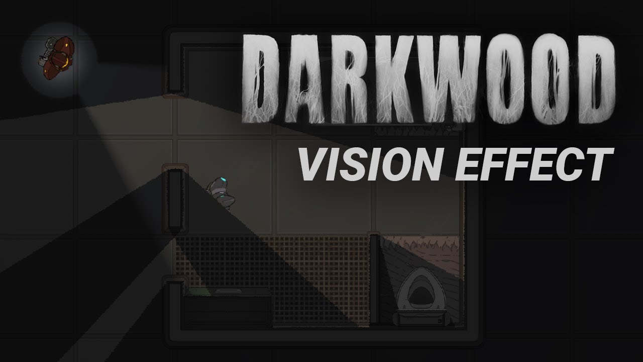
I had this idea in my mind for quite some time now and recently I had some free time. So here it is I guess.
Source code:
https://github.com/aarthificial/darkwood-vision-effect
Support me on Patreon:
https://www.patreon.com/aarthificial
Art by "Omnihunter" project:
https://opengameart.org/content/top-down-basic-furniture
Gameplay by Nokzen:
...
how can i recreate this ?
i don't understand what he does in the video
Is there a way to create ambient occlusion using shadergraph?
No, shader graphs operate only per-vertex and per-fragment
AO by its nature requires calculations spanning more than one fragment/pixel
Post only to one relevant channel please
the video is about shaders
What about screen space ambient occlusion?
And screen space shader graphs in general.
I thought it had to rely on compute shaders to properly use the surrounding pixels for the distance and blur calculations, but I guess it could be done
Don't you need a whole new texture sample for every point of the depth and color textures which you'd read in a full screen shader
I can't confidently say
I think ddx/ddy is often used for that. It can give you data of the pixels in the same quad/fragment(or whatever it's called)
It is, but it's not nearly big enough for AO, or hardly any blur effect either
How about just sampling the positions and the normals of the surrounding pixels in a radius and if there are some that have normals different enough from current pixel, darken the color?
I guess my question is if sampling the screen texture multiple times for a blur or proximity effect in a fragment shader is more expensive / "worse" than reading it in a compute shader
It could work, but to have smooth and good looking AO, you need to sample a lot of pixels if you do it in a single pass.
Good question
I see.
Afaik texture sampling is the only way to do it in just one fragment, and it's preferable to have few texture samples in a shader
No, perf is about the same.
But SSAO relies on multiple downsample blur passes to work, then applying the effect is lighter by using those blurred buffers instead of doing a single pass blur with a lot of samples per pixel
I guess downsampling has to be done outside of the shader graph, but the rest of it could be done inside?
If you mean still doing the blurring in shader on the downsampled screen texture, then that's still more expensive than doing the blurring outside and just doing a final sample in the shader.
Who would even know enough to implement AO in shader graph but not be able to write some simple HLSL instead 🤔
We're assuming they meant screen-space real-time AO. AO can also refer to AO textures, or some special cases where you can simplify it, like many voxel/Minecraft-esque renderers do.
but they probably meant screen-space ao
Probably ^^
I think all render pipelines have SSAO to begin with though
And if you were making one from scratch, compute shaders are probably the better tool for it
It doesn't necessarly have to be compute. Downsamling and AO can be done with regular pixel shader passes.
SSAO is basically bloom, but instead of filtering bright pixels, we filter for creases (by comparing neighboring normals)
well they are the same as in they both are post processors in screen space
but finding all the bright pixels, bluring them then adding it on top does not really feel the same as using normals to find creases
Nothing wrong with good ol' fashioned vert/frag AO. Keijiro has an old (but still great) SSAO effect on his github
But doing it in shadergraph you'll run into the problem that shadergraph breaks (at least in HDRP) when you try to throw any mildly complex fullscreen post-processing at it

Does anyone have any idea why the HD Scene color is incorrect?

Applied to a plane there in front of a character to show it off
Am I missing something?
It looks like this is a Lit shader and scene color is being applied to base color, so your material will be affected by scene lighting
Yeah I need that for a frosted glass effect
What if you uncheck exposure?


And unlit
What do you mean?
If you use an unlit shader with exposure unchecked

I see.
Yeah the exposure is needed
And I need the lit shader too because it needs to be affected by scene light
That is all expected
HD Scene Colour = pre-PostFX
So it will not have tonemapping etc on it which is worth considering
That must be it, it does indeed look like the tonemapping is off axis
Any way around that, seems like an odd limitation?
It's really not a buffer that's meant for 1:1 replacing the scene colour, it's more of a "useful for stuff that can look a tiny bit different" buffer used for stuff like bloom, some blurred refractions, etc.
Also it's broken half the time (in FS PostProcessing Shader Graph it doesn't work) but that's a separate story
In another project I got it close by color correcting in the shader, but that does not seem like the most optimal way to me
Do you have a suggestion for a better way to do a glassy refraction?
Only other thing to mention is try ensure your shader graph is using the correct precision - that might also be affecting it (if it's trying to render a fixed precision when the rest of the pipeline/scene colour then should still be float prec.)
Yeah the precision is set correct
Very annoying 😦
I guess I'll manually try to correct it a little again

It's not the tonemapping though, this is with tonemapping off
It's like HD Scene color uses it's own limited tonemapping


Whatever
Close enough for anyone who cares
coming from this*
So I have what are essentially 2D sprites that I'm implementing in 3D. For simplicity's sake, I want to have my normal maps for my objects represent their 2D perspective(as though I'm applying a normal map to a 2D sprite or a flat quad). However, my objects are going to be applied to a 3d mesh(like a cube), and thus my normal map won't work out of the box. How would I go about achieving this with a custom shader graph? I currently have an unlit shader, and I have a custom function for recreating the lighting, as I essentially want to do all of my object lighting with normals instead


basically I am hand-making all of my normal maps and I don't want to try to take into consideration how the normals would change on a per-face basis when I'm pixeling them
Set the shadergraph to use Object Space normals 🙂
You'll also want to export your texture as default without sRGB .
And sample them as "default" textures.


ah that seems a lot closer to what I was going for. Thanks! Though I am aiming for an unlit shader as I want to disable default object shading completely(as it conflicts with the shading that the normal map is doing) so that option is (obviously) gone. I have a custom lighting node function but I can't seem to wrap my head around the transformations. My results are close but don't quite look right?


Hello everyone, i have been looking far and wide for this typ of shader in the glasses. Would anyof you know by any chance? When looking head on its okay but on the side its almost an RGB distortion?


- According to the red-ish tint of the texture, You are still importing it as a normal map, but you should import it as a default 2D texture, with SRGB disabled.
- Between the sample and normalize nodes, put a "remap" node, that remaps from the [0;1] to [-1;1] range. Since RGB colors can't be negative, but normals XYZ can, that's how it is unpacked.
Looks like a screen space refraction shader, Doing 3 refractions taps for each RGB component, with slighly different refraction indices.
Thank you, now that I have the name I'll look for it, and if not I could try make it
Sorry I somehow missed that. I also ended up with what I believe is the same solution as you. I derived a class from the image component, overrid OnPopulateMesh and baked in linear uvs in uv1.
Yeah sounds similar, my is applied as a effect though so still using the original image
It surprising it's not like this by default
Things look so much better when you can 9 slice for nice crisp edges than add gradients or pattern
Agreed. I'm also not sure why this isn't default. The overhead of adding linear uvs to uv1 within the image class would be so little.
If you get a sec, would you mind sharing so I can compare the pros and cons?
Here's mine
https://pastebin.com/rdCfaNPb
It's not great cause it needs to repopulate the UIVertices but at least it retains the optimized mesh
Yeah give me a bit, will have to boot up my work machine
Thank you, no rush I come by every once in a while, I'll read you then if now isn't a good time
Pastebin
Pastebin.com is the number one paste tool since 2002. Pastebin is a website where you can store text online for a set period of time.
more or less exact same approach as yours, just doing it via BaseMeshEffect instead of deriving image
I like yours much better. The extra image component is a bit of an annoyance. Would you mind if I used your code?
go for it
also added the uv channel selection in case it ends up on a component that already does stuff with uvs
Not sure if you care, and it's not really a big deal, but GetUIVertexStream gives you the unoptimized mesh, so if you did this in your code
print(helper.currentVertCount);
helper.GetUIVertexStream(verts);
print(verts.Count);
You'd see a discrepancy in vertices count. You end up with the unoptimized verts. The solution I found was to manually populate them 1 by 1 to retain the optimized mesh.
Thank you very much
good to know, never noticed that but would explain a few weird edge cases
though not sure it matters since i manually populate when doing the actual modifications, the first loop is just getting my min and max so i can decide where the 0 to 1 space is
Hah, you are absolutely correct. I'll see myself out now
Wait no
You still populate in function of helper's length, and helper's length is modified when you fetch the vertex stream
but yeah good luck, it helped alot for getting the look i want, and yeah i will make the looking for the width and height consistient with the rest
Wait nvm I'm dumb
really will not say its optimized, i more or less just remebered this BaseMeshEffect class from before TMP exisited since its how you added shadows back then and just went for it with the api i saw without much actual reasearch
It's more than fine for my needs. I just needed glossy light shines on 9 sliced buttons and the likes. It's super handy to have. Again, thank you very much
yeah i use it for the same purpose, some shaders using it directly to just more or less add the V coord back on top of things to add a gradient
then a few shaders use it to map a actaul image based on the 0 to 1
like a circular shaped highlight on UI headers etc, or a really subtle pattern
just find it odd unity does not do this by default, i have worked on a inhouse engine before and i more or less added this by defualt when i added 9 slice support
absolutely, there is a clear need to span effects linearly across images in general. I agree
I need help with a Text Mesh Pro shader I'm working on. I've gotten pixel-perfect outlines working on Text Mesh Pro text, but the problem is the mesh itself that it's being drawn onto. Because the mesh is so tightly fitted to the letters, the outline does not draw correctly.
Extra Padding helps, but it isn't enough padding, and looking through the code of the TMP object, I can't find a way to make Extra Padding produce even more padding than normal.
Does anyone here know a way to increase the actual mesh size of TMP text, beyond what it normally uses?
not sure how useful it is to anyone else but I'm proud of making this for myself. to display a value in shader graph as an actual number. I wanted to interrogate what actual values were being passed back and forth, and this lets me look at what the actual numbers are. I'm sure there are fancier versions of this around but this one is mine...
https://drive.google.com/file/d/1ZnUGoF5LyvaKH7kSlOp_fKvruV-P1Y4d/view?usp=drive_link
https://drive.google.com/file/d/15fAuA0kQzslvKBMR-7QlaWeNgs1bIgYZ/view?usp=drive_link
https://drive.google.com/file/d/1L0mBmo8SUm_NCeext-ggQBFAvvtY77SK/view?usp=drive_link
Google Docs
Google Docs
Google Docs
thats actually quite neat
for some reason the bounding box? of a light is affecting the color of my material
void finalColor (Input IN, SurfaceOutput o, inout fixed4 color)
{
    color = _DarkColor;
}
im using a final color thing, which has worked fine except for this issue. I can show the whole file if needed

but in theory a final color should be... the final color
Shader "Custom/Cell" {
    Properties {
        _MainTex ("Base Color", 2D) = "white" {}
        _BaseColorMultiplier ("Base Color Multiplier",Float) = 1
        _Normal ("Normal", 2D) = "white" {}
        _Dither ("Dither", 2D) = "white" {}
        _LightColor ("Light Color", Color) = (1,1,1)
        _DarkColor ("Dark Color", Color) = (0,0,0)
        _Bias ("Bias", Float) = 0.5
        _LightThreshold ("Light Threshold",Float) = 0.75
        _DarkThreshold ("Dark Threshold",Float) = 0.25
        _DistanceFog ("Distance Fog",Float) = 0.1
    }
    SubShader {
    Tags { "RenderType" = "Opaque" }
    CGPROGRAM
      #pragma surface surf SimpleLambert fullforwardshadows finalcolor:finalColor

      half4 LightingSimpleLambert (SurfaceOutput s, half3 lightDir, half atten) {
          half NdotL = dot (s.Normal, lightDir);
          half4 c;
          c.rgb = s.Albedo * _LightColor0.rgb * (NdotL * atten);
          c.a = s.Alpha;
          return c;
      }
    sampler2D _MainTex,_Normal,_Dither;
    float4 _LightColor,_DarkColor,_Dither_TexelSize;
    float _Bias,_LightThreshold,_DarkThreshold,_BaseColorMultiplier,_DistanceFog;

      struct Input {
          float2 uv_MainTex;
          float4 screenPos;
      };
      fixed4 _ColorTint;

    void finalColor (Input IN, SurfaceOutput o, inout fixed4 color)
      {


        color = _DarkColor;
      }


    void surf (Input IN, inout SurfaceOutput o) {
        o.Albedo = 1-((1-tex2D(_MainTex,IN.uv_MainTex))*_BaseColorMultiplier);
        o.Normal = UnpackNormal (tex2D (_Normal, IN.uv_MainTex) );

    }
    ENDCG
    }
    Fallback "Diffuse"
}
heres the whole shader
I changed the finalColor to be simpler but it did the same thing before (thats why it seems weird)
this is odd
wait
I think I understand
its executing the final color for each light
so when the lights overlap
ohhhhh
thats weird
heres the thing
when I put nothing in the final color function it has no artifact
if I do color = float4(color.r,color.g,color.b,1) no artifact
but the moment I do color = color + 0.1 theres an artifact
but why would it make the color lighter if im just setting the color
color = float4(0,0.5,0.5,1) has artifacts
both forward and deferred have the artifact
im stumped
the issue is I can't find ANY documentation about the finalcolor thing
I can't even find where I originally learned it
theres something here
its seems like its something to do with objects overlapping and the finalcolor being like
applying to previously rendered objects
but it happens with one object as well
something to do with lights and shadows
so it seems to be rendering twice but I still dont see how that would change things
if the final color is being set to a constant value
it draws for each light
which makes sense I guess
but what doesn't make sense is why the finalcolor is being... overridden? or something?