
#archived-shaders
1 messages · Page 84 of 1
yes. it's called Outside.hlsl
Yep the shader hires a whole team of professionals to make same awesome visuals for your game
First time using shadergraph and im failing at it ;-; so I basically need a shader which is the same as the defualt urp lit shader but with 2 main base textures which I can switch nicely between. Ive got the blend /switching working but the material doesnt look correct, its way darker than it should be. Ive attached two photos, one with the normal lit shader and one with the shadergraph one that I made. What am I doing wrong? Ive included my main shadergraph and then two sub classes. Really appriciate any help :) Thank you


On the NormalMap sample you want Type set to Normal
And likely want Normal Output Space in the graph settings to be in Tangent space rather than Object (depends on the type of normal map)
Make sure to change the NormalMap property type to Normal as well (under Node Settings tab of Graph Inspector window, while property is selected). So that it's correct when you have no texture assigned
hi im new here
can someone help me fix these artifacts? there is a weird black box around my potion pixelart whenever i add a texture to the metallic slot

for some reason its also in the preview

but this is the original image

Does ticking Alpha Is Transparency do anything?
Otherwise would try importing as Single Channel type, or edit the texture to be greyscale rather than using transparency
i was just fiddling with it just now

it gets rid of the box but now it doesnt look as intended
i only want to make the white parts shiny and the black ones diffuse
here is the full colored image if it helps as a reference

NVM GOT IT WORKING i have no idea what "single channel" means but it now works perfectly

Thank you so much, massive help
when you do ShaderID.SrcTex, what is that?
Shader.PropertyToID("_MainTex"); in a utility class you made?
This my Execute method:
public override void Execute(ScriptableRenderContext context, ref RenderingData renderingData)
        {
            ref var cameraData = ref renderingData.cameraData;
            var cmd = CommandBufferPool.Get("_QuantizeRenderPass");

            using (new ProfilingScope(cmd, profilingSampler))
            {
                //s_propertyBlock.Clear();

                cmd.SetRenderTarget(_target);
                cmd.SetGlobalTexture(s_mainTex, cameraData.renderer.cameraColorTargetHandle);
                cmd.DrawProcedural(Matrix4x4.identity, _mat, 0, 0, 3);
                cmd.Blit(_target, cameraData.renderer.cameraColorTargetHandle);
            }
            context.ExecuteCommandBuffer(cmd);
            CommandBufferPool.Release(cmd);
        }
And this is my shader, which I practically coppied one for one from Hidden/BlitCopy: https://gdl.space/mayoyiqeha.cs
But still a gray screen
actually Hidden/BlitCopy is gray too, so...
Oh, yeah, it's Shader.PropertyToID("SrcTex"). I just have a massive static class filled with PropertyToID
You want to blit from camera color to target?
Use BuiltInRenderTextureFormat.CameraTarget instead of cameraColorTargetHandle
hmm ok. I'm starting to finally get results. I have this so far, which is working:
https://gdl.space/xafulelomu.cs
This is my Execute method now:
        public override void Execute(ScriptableRenderContext context, ref RenderingData renderingData)
        {
            var cameraData = renderingData.cameraData;
            if (cameraData.camera.cameraType != CameraType.Game)
                return;
            if (m_Material == null)
                return;

            CommandBuffer cmd = CommandBufferPool.Get();
            using (new ProfilingScope(cmd, m_ProfilingSampler))
            {
                Blitter.BlitCameraTexture(cmd, m_CameraColorTarget, m_CameraColorTarget, m_Material, 0);
            }

            context.ExecuteCommandBuffer(cmd);
            cmd.Clear();
            CommandBufferPool.Release(cmd);
        }
I copied the main body of the shader from a page on the URP docs. But I'm not sure why my other one wasn't working?
I want to use my shader to modify the camera's texture
Yeah, I've had more luck using the built-in constant rather than trying to get it from rendering data but if that works, go for it
im just glad I'm finally making progress. I have no idea why the other stuff wasn't working, looking it up there's not a ton and everything says to do it a different way haha
Yeah. It's all over the place
since you're here @median gull, what would be the proper way to branch in my shader? I want to add a posterize step, but only if my posterize steps are above 0.
Use an if() {}
Yes yes, branching bad in shader code but unless it's really expensive, just do an if
is that "proper"? Because I know there's different types of branching that effect performance in different ways
I read something that said if the branch is the same for all fragments it won't impact it that much
Proper is a loaded word. Really depends on what you're doing with it, whether it's warp constant or varying, and how expensive are either branches of the conditional
https://learn.microsoft.com/en-us/windows/win32/direct3dhlsl/dx-graphics-hlsl-if
I saw that I can apply attributes to the if statement? (I'm using HLSLPROGRAM)
I recommend 99% of the time don't worry about it. HLSL is pretty smart in that it'll know when to branch or flatten. You can add either attribute to your if statement to see if it affects performance but I've never had to use them
what are these pragma directives doing? I see Vert is defined in a package that is included, and frag is the fragment shader method, but what do they actually do? Tell the shader to run those methods?
#pragma vertex Vert
#pragma fragment frag
Yes. For a "simple" vert-frag shader, this tells the GPU which functions are the vertex and fragment shaders.
You can have more like Geometry stage or the madness that is tesselation (hull-domain-stream) stages
spooky
Pragma stages are unity specific, I don't think HLSL has these directives. They specifically link the required shaders in c++ draw sequence.
btw, if my shader is not referenced anywhere (I'm creating material at runtime), I need to add it to a shader variant collection and include at least one variant for a build right?
Trying to save myself from future headache
No, you just need to do new Material(Shader). The shader needs to be referenced somewhere like on a monobehavior inspector field
Ive never used shader collections personally. I don't have that many that needs to be bundled.
yea, like if I dont' reference that field
like if I do CoreUtils.CreateEngineMaterial("myShader")
If you dont reference it then yeah, you'll need to add it to a collection somewhere so the build doesn't strip it. I don't think names are enough
thanks
In shadergraph, is there a way to get the direction a face in a mesh is pointing at, and calculate if it's opposite to the direction of a present light?
normal?
and if you can get the light direction, you can just use dot product the normal and the light dir to check it
Hello, I am trying to center a texture on an object in screen space so that the texture is always facing the player but does not move in screen space. Does anyone have any idea how I could accomplish this?
heya, is there a way to pass a struct to a (not compute) shader without a structured buffer?
any shader-graph pros here? i really need some help with my logic.... i am trying to make a shader for my custom terrain that sets the texture based on y-value and steepness. i managed to make a shader that does this as intended, and its looking great, but the edges do not transition at all, and i am completely lost on how exactly i could implement this... it would be a huge help if anyone could assist me.
Hello everyone, I had a question, does anyone here know how to create a transparent distortion effect (think of heat distortion) in Unity post 2021 update? I've been looking at tutorials for hours now and can't seem to find a proper solution for 2021. I was wondering if anyone here had a similar issue?
I'm in the URP pipeline in 2021.3.3
WDYM by "the edges do not transition at all" ? Can you share some of the graph setup ?
On 3D objects, or as a fullscreen effect ?
In both cases, it involves using the "Scene Color" node, either in an unlit shadergraph, or a fullscreen shadergraph
This is on a 3d sphere, I've set it up using the scene color node yes on an unlit graph
Can't seem to achieve the desired effect
It would help if you could show the current result, your graph, and explain what is wrong + what you want to achieve.
Oh my apologies, I'll get that right to you, one moment
I want to be able to distort the light coming through the object, I am trying to begin making an Energy Shield for my portfolio and I can't seem to get the distortion to play nice haha


Note that your twirl effect it based on the object UVs, so it will "map" like a texture on the object surface. Is this maybe the issue here ?
Oh? I did not know that, I'm a substance designer guy trying to adapt his skills to the unity shader graph. So I am still trying to understand the ins and outs. How might I fix this issue?
That comes from the "Rotate" node. Its 1rst input is using the "UV0", which are the object UVs.
If, like I suspect, you want to have a sreen facing swirl, maybe the easiest would be to apply you material to a screen facing quad ? 🙂
Else, you can still use it on this sphere, but it will require a quite complex setup of nodes to fix this issue.
Right I see, interesting how it changes like that, I'll put it on a plane and see if that fixes the issue, otherwise I'm open to learning this more complex node setup as it's an oppertunity to learn
no change unfortunantly

Did you try to place it in front of the tree like the other one ?
The tree image is not mine, it is the desired effect I want to achieve
Oh, so that tree picture is from a tutorial, not something you actually have on screen ?
Yes, unfortunantly
Is you shadergraph / material surface mode set to "transparent" ?
Hum ... it just looks like the scene color is not working. If you place something behind the object, ie a red capsule, it doesn't show through ?
Not a red capsule but a textured object I had in the content drawer, still no effect unfortunantly behind the quad

Ok, but it is showing through the quad , right ? Or are you looking through the back face of the quad ? 😅
This at least removed a potential setup error
not Showing through the quad

Try to expose a float property for this multiply value, and boost it to see if it has any effect ?

One moment
No effect, float is at 500

Perhaps it could be a version issue? Maybe I ought to go to 2019 since this is a portfolio piece
What version are you currently on ?
No, that's fine, I don't see why rooling back to 2019 for a portfolio
Yeah, it'll just mean I cant work on it at Uni though
which would suck
Cuz I've got alot of time tomorrow to refine my portfolio
... iirc, it should work with 2019 if you need to .... why not update the editor version in the Uni then though 😅
Don't got permissions to
They've only got one version on all PCs
said it's the most stable
🙄 meh ....
Oh well
I'm not gonna cry over it, I can always do something different for my portfolio tomorrow
Anyway .... If you do a very dumb test, like add you exposed property directly to the screen position value, before the scene color node, doesn't it "shift" things behind the quad ?


Well, no, but it should have made something visible 😅
At that point, I'll start to ask the dumb questions : you've saved the graph, with the top save button, right ?
Of course?
Because it doesn't seem to change, and other dumb thing : you're not editing the wrong graph ? Like, if you set the output color to .... blue, it does display blue (sorry, but I'm getting out of ideas now) ?
same graph but blue

Oh ... Hey, alpha is 0.5, is that wanted ? You might want to set it to 1 for testing purpose, until you are sure the disortion is working properly.

Scene color node, without anything plugged in the UV input (so it should display without distortion) ?

Blue ?

Something is wrong with the scene color apparently.
Do you have multiple quality levels in your project ? It is possible that each one has a different URP asset assigned, be sure to check opaque texture to the current active one, or simply on all of the URP renderer assets in the project.
The boxes are checked, I wouldn't know if this is what you meant, but I changed the shader from transparent to opaque


I changed the shader from transparent to opaque
The shader needs to be transparent
my apologies, changed it back
What did you mean by this?
Here, each of the quality levels can have a different pipeline asset assigned. If the current active one, "Ultra" in my case, doesn't have opaque texture enabled, it won't work.

gotcha
ah would you look at that, I had a different URP settings asset I was altering, I connected the right one and it fixed it

Thank you
Finally 😄
I think most of them assume that you only have 1 urp asset, assigned in the global graphic settings
Well that fixes my issue, I just wanted to solve that error so I can go into uni tomorrow and make this effect for the energy field I was creating
Thank you for the help, means alot
Im off to bed now
yeah, i can dm you the details if you have a few minutes to take a look...
You can post it here, make it a thread if you feel like it would clutter the channel.
blending terrain graph
Hello, I am trying to center a texture on an object in screen space so that the texture is always facing the player but does not move in screen space. Does anyone have any idea how I could accomplish this?
here's one: #archived-shaders message
Or maybe what you ask is the opposite of that?
ok, putting this into the coords, I see the coordinates just stay on the object and dont follow the camera


If you don't want to follow the object you probably can just use view position as the UV
only issue with that is I want the texture to stay central to the object and not scale with distance
that's where I'm struggling to find a solution
I guess it's unclear to me if you mean the not scaling and moving in screen space relative to object's or the camera's motion
In an ideal world, I'd like the texture to display in screen space on the object but the texture to stay centered on the object when seen from the camera's perspective and scaling with the camera's distance like a standard texture would
That's how I'd describe the linked solution
Perhaps maybe I'm using the rotate node wrong here then
You want View on the Position node. Or use Screen Position node and World->Screen in the Transform
How would one go about creating a fuzzy halo around a sphere like this?

Or something like this

a soft glow behind the object
transparent inverte fresnel showing backfaces or something?
a second sphere with a larger scale make it transparent and then apply an alpha based on the dot product of mesh normal and camera forward
looks like some sort of simple atmosphere shader. In this case it looks like very simple shader would be enough to simulate atmosphere like that
just something like this?

ah thank you! I actually was curious about the second post you linked here
#archived-shaders message
This fixes so many issues but I cant seem to keep the object actually centered as it slightly skews with distance and position but it's so awesome that I can't help but wonder if there is a fix for that issue
This is going to be a stretch but has anyone implemented DLSS in SRP (not HDRP)

Anyone have idea why the Standard shaders have issues on Mobile devices? We see reflective rendering for normal diffuse textures
I see something like this. When it should have been just a normal diffuse.

This is rim lighting. The standard shader is a PBR shader.
I'd recommend using a simpler shader if you only need the diffuse texture. At the moment you're paying a lot more than what you're getting in terms of performance.
I tried the mobile/diffuse shader and I see the same reflective rendering still
not sure what is causing this
It's also called fresnel effect in unity
https://docs.unity3d.com/Manual/StandardShaderFresnel.html
I don't think this should happen with a mobile diffuse shader.🤔
I guess its some Unity render settings that is causing this issue Not entirely sure though.
Can you demonstrate the issue happening with the diffuse shader and the material settings at that time?
Will try to share the screenshots for the settings
I did a few test it was my mistake it was the shaders itself. It was the standard shader creating problem thanks for the support @kind juniper
can someone help me understand how can I make UI shaders? I want to make this blood splash reveal with voronoi effect smoothly over time (i will control a parameter in the script)

however with the setup i posted above, my Image with attached material with the shader I created is a blue square


am I supposed to create Canvas Shader Graph? I created Unlit Shader Graph
yes, you need a canvas shader graph
Hello, got a (hopefully simple) simple canvas shadergraph question.
My game is 384x216 pixels in resolution, so I do a number of tricks to ensure everything is on that pixel grid. UI however seems to always render out to the normal screen resolution, so if I rotate an Image it doesn't pixelate the way I want.
In this picture, the checkerboard pattern is at the pixel resolution I need, but you can see it's rendering the edges of the rotated Image at a higher resolution. What would I do to the UV or some other aspect to eliminate the subpixels on the edges of a rotated Image in shadergraph?

Hey, guys my shader works fine in vulkan and it looks fine on editor in both windows (DX11) and on mac(metal) but when i make build for OpenGL my shader doesnt interact with fog

anyone has any idea?
how to fix it?
Quick and easy question - I have a WindMaterial that I change in PlayMode inside a script to control the weather. But the script changes the values inside the material asset file which persists after ending the Play Mode which is very annoying. What's the best way to change a property for every material instance in PlayMode but without affecting the file on disk?
Hi everyone!
So kind of random -- but does anyone know why this gold / white outline could be rendering in my reflection texture?
Is there some setting that I should take a look at to get rid of it?
I didn't notice it earlier since my floors were light / pastel colored, but since this one is dark, it's showing up.
Attached are screenshots of my reflection shader graph along with the player texture for it.
Any help is appreciated, thanks!! 🙂


You want the texture resolution to match your checkerboard and if you want it to be checkered even in rotation, you'll need a custom shader to clip subpixels
That last part (custom shader to clip subpixels) is what I'm trying to achieve, but I'm unsure how to pull it off.
For more context, the only texture being used is from a texture array to handle dithering as a replacement for shading. Otherwise these are entirely one-colour procedural shapes done in shader graph.
Do you want the checkerboard to be aligned with the screen?
The checkerboard isn't so much the issue, I just used it to make it clear what the pixel grid was in that case. As without it it would've been difficult to highlight the subpixeling at the edges.
Basically trying to take an Image and make it look like this when rotated, so that's it's pixelated and matches the pixel resolution of the rest of the game

Well, as in will the full pixels be aligned with the screen when rendered? Because you can just check in the shader whether current pixel (SV_Position in frag shader) divided by your "pixel" size that you want
If the jagged edges need to be aligned along rotated axis (such as when the camera rotates), that's a slightly more difficult process.
It's entirely in UI, so there'd be no camera rotation. These are all Images, as in the Image component, for the rendering
Also I'm working in shadergraph in 2023, with the canvas option
Okay, hrm. Have you tried rendering to a smaller texture then blitting it to screen?
I do that for the scene itself, it goes to a render texture and then displayed in the game's viewport, and that works great.
I was hoping to avoid that for the rest, as the enemies are 2D sprites overtop of that viewport, and so far I've had decent success in getting the various FX into the UI in that same canvas. That way I can set rect transform markers on characters as origins/destinations of effects, and translated them accordingly.
Rendering them elsewhere to a separate camera, and to a separate render texture is possible, but was hoping it'd just be a fallback plan
The other option is a per pixel check, floor/round/ceil your pixel position on the screen to the nearest "coarse" pixel, calculate using an inverse-view-proj-model matrix to go from screen pixel to unit square, then check if the pixel belongs to a subpixel group outside the box. Discard/clip the pixel otherwise (clip(abs(objPos) > 1 ? -1 : 1).
No clue how to do that in shadergraph but that's all within about 3 lines in hlsl
The former I mostly do by changing the UV so that U and V are set to the nearest multiple of 1/pixel size of the image. But that fails for when the Image is rotated.
Unfortunately I don't understand the matrix component of your solution. I know there's matrix methods in shadergraph, but never tried matrices
Hmmm, guessing it's in here though

the last one I guess
Not quite, you'll need inverse model as well to support rotation.
Think about all these matrices as converting between "spaces". There's really only 5: Object, World, Camera, Clip, Screen.
Object is what your object is originally imported into unity as. Unrotated, un-translated, unscaled. No parents affecting anything. You can have built in rotation/translation/scale but not any that Unity programmed.
But if you want to move an object to the left 5 units or rotate in world space instead of staying at (0,0,0), you need to convert the object space into world space.
Thats where the "Model" matrix is. It's a massive matrix to convert your "local" position into "world" position.
But that's not enough for rendering, D3D needs to know where it's on the screen, so you have View-Projection (two matrices).
View is actually the inverse Model matrix for the camera, since that's where things need to render relative to the camera.
Inverse being instead of local -> world, it's world -> local (like multiplication and division)
Projection is a special matrix relating to camera properties like field of view and clip planes to convert the mesh to a uniform [-1, 1] space called NormalizedDeviceCoordinates or Clip space.
So you have a problem where you want a shape to be aligned along Clip Object Space coarse pixels when you rotate something, so you need to convert your pixel to object space, do your math of 1/pixel size, then convert it back (since UV division is what you wanted, not screen space uniform pixels, sorry).
Hrm, you might need to go to clip space with the UV
Screen space uniform pixels is actually what I want. The UV thing I did works nicely when there's no rotation, and when the Image's rect transform local position is snapped to the nearest pixel.
The UV trick also works if I do any in-shader rotations, as long as I pass that coarse UV along to any node that takes a UV, and remember to floor/ceil results accordingly that might stray off that coarse UV.
The reason why I'd like to see if this could work with a rotated Image, and only rotated in Z, so it's always flat towards you, is for effects where I'd normally use a line renderer. But line renderer doesn't work in UI, so this is my workaround attempt
Basically drawing a line in UI between elements
Non-aliased line renderer?
Yup, completely non-aliased, to match the pixely retro look. Lemme show a quick vid of what my viewport looks like
Oh yeah, hrm.
Everytime I think I have an idea, I remember that fragments don't know much of anything about their neighbours 😅
Take the coarse UV and test the dot product of the UV (finds the angle) against 4 rotated lines that make up the rectangle.
If the dot product is negative, clip.
Lemme try that
It's going to be trying to find the line vectors that is going to be most interesting. Good luck.

The problem will be rendering partial coarse pixels, as it'll be clipped by the rasterizer and there's no way to render pixels that the rasterizer said no.
The red line being the edge of your quad and the big blocks being the coarse pixel (seen in the checkerboard).
I'm fine with coarse pixels being completely dropped if even one of their screen subpixels would be cut
If you want to prevent partial checkerboards, then you need test all 4 positions of the coarse block rather than the center. (0,0) (0,1) (1,0) (1,1) against each of the 4 lines that make up the edge of the quad
Oh, would DDX/Y apply here? I remember trying it out a while ago to find edges, and it kinda worked
Actually, you'll need to test the vector between the 4 corners and the orthogonal of the line making up the edge of the quad (which is just (-y, x) in 2D space)
Deriviatives wont help here because your coarse pixels are larger than a 2x2 actual pixel.
They're a cheap way to check if there is an actual edge between 2x2 pixel block but if a transition occurs across multiple pixels, then it cant return anything usable
Gotcha. I tried anyways and just passed the raw DDXY output to color, and it gave me an interesting grid effect of 2x2 coarse pixels
If you design your game around 2x2 blocks, it might work?
Heh! Well, the render texture approach would be a better fallback than to chunkify my visuals even further 🙂
Yeah, the render texture will be the easiest way to do it. Probably through a custom render feature if you're in URP.
Understanding matrices sounds like my best avenue here then, and that will take a while. Haven't touched them since university, and forgotten everything about them
Well, and the render texture if I can't figure matrices out
I honestly don't know a thing about matrix multiplication but the concept of transformer matrices are fairly simple.
Well, figuring out the 4 vectors of the rotated object will be the complex part, as you mentioned. Their rotations won't be an issue, since I can just take the object rotation and rotate that by 90, 180, and 270 for the other 3, but then placing them at the boundaries will be a challenge for me
Thanks for explaining the proper process for all of it, I'm gonna copy paste this down for a future me more capable of the task
Yeah, sorry for not really explaining this well. It's possible and (relatively) straight forward. But it'll require understanding matrices and space transforms.
I think you did a decent job of the explanation, but I need to brush up some fundamentals before it will all click
Hi,
I would like to modify shader to "Bumped Specular" though, I cannot find any changeable items in Inspecter.
Can anyone tell me the root cause ?
I made custom function and i can't connect my UV to Texture UV, why?
#ifndef VOXEL_MESH_INFO
#define VOXEL_MESH_INFO

StructuredBuffer<int> Indices;
StructuredBuffer<float3> Vertices;
StructuredBuffer<float2> UVs;

void GetVertexData_float(float vertexId, out float3 position, out float2 texcoord)
{
    const int index = Indices[round(vertexId)];
    position = Vertices[index];
    texcoord = UVs[index];
}
#endif

Does it give an error, or just refuse to connect?

Can't use the same node in both vertex and fragment instances, so make a new one
refuse to connect
Hi, sorry if this is the wrong place to ask, I am p sure I messed up my shader and I don't know how to fix it.
I am trying to add a normal map to a simple sprite shader I have(Picture 1) and it kind of works but not really.
Instead of appearing over the sprite, it's just a tiny bump in the middle of it(you can see the whole normal map if you zoom in enough, Picture 2).
My import settings can be seen on pictures 3 and 4.
And finally my material settings are shown on the picture 5.
Thanks in advance!


hm i use VertexID to get position and uv for block, but then i cant use vertex id, what should i do then?

please @ me if you are able to help
bump
2D Light texture doesn't use UV0, it uses Screen Position, in Default mode iirc
Side note but you might want to use sprite secondary textures for the emission and normal maps, rather than texture references in the material
Also, what's with the glare overlay in the screenshots?
hI! So I would like to perform frustrum culling taking into account the directional Lights for shadows. How can I get their Projection Matrix so I can check the clipspace?
There is no way to access the shadow matrix that Unity calculates for lights, except in shaders through draw calls Unity submits.
Can I somehow get them for compute shaders?
Otherwise I guess there must be a math way to fake it If I have access to all directional lights
Unity won't pass lighting properties to compute shaders, so I think you'd have to read it from a dummy draw call and do nothing in it but write it to a StructuredBuffer which the compute shader then reads.
You can try to emulate what Unity does to calculate the matrix. Of course, if you're using shadow cascades, there will be multiple matrices, but I assume you're interested in the biggest one for culling.
There's not necessarily an obvious method that Unity will be using for calculating matrices for directional lights. There's no perfect matrix for a given directional light. The fact that it's orthographic is a given. Its rotation could be anything, as long as the forward axis is pointing in the same direction as the light. The center of the matrix and the size of it could also be anything, but probably somehow dependent on where the camera is.
mmm, so what should be the way to go to perform furstrum culling in shadows?
(In the GPU Instancing world=
Hello, i have a specific viewport shading matcap material in blender that i like the look of. it's the clay_studio one. I was wondering if anyone knows if a similar look can be done in unity or if someone maybe has made a shader to look like that?

I am using URP in unity
Do you mean something that imitates the look of that material, or do you want the specific kind of matcap shader that blender uses for all its matcaps
heya, for some reason when i set a float array in the OnEnable in an [ExecuteAlways] MonoBehaviour, it just doesn't set it, anyone know why?
works fine in an OnValidate
Same with Execute in edit mode ?
something that looks like the clay one it does not have to represent all the others
i think the clay one just makes the low poly model look well
Since that matcap is created to simulate a kind of soft studio lighting on a white material, you could reach very similar results just by placing light sources in a similar way, and optionally with the help of a HDRi
Here's a matcap shader graph, which you can use with blender's matcap (if license permits) or find or make another similar one
sure, i do have objects that i want to use with that type of look that move around so i am not sure if lighting alone will be enough but i'll check out the file you send
That was the issue, thanks a ton!
It also fixed some other weird light behaviour I had.
I am already using them, I just wanted to make sure everything worked properly on that end so I tried explicitly defining them.
Really sorry about that, I have all my windows semi-transparent so they match my system theme better, will make sure to toggle the transparency next time I am sending screenshots, it's 1 bind away anyways.
Hey, I am not particularly shader capable (planning on committing some time to learning the basics soon) and I have done the shameful thing of just copying a shader from a forum post which has worked really well but there are some creases to iron out which I am hoping some shader wizard can help me with. The shader provides a grid for my building system as can be seen in the first image, the grid is great but it currently is cast on top of everything (including grass which is why it looks fuzzy). I think the possible solution is playing around with the render queue but I don't understand how I could make that work as the geometry is lower down the render queue then transparency which is what this shader is...can you tell I don't understand this stuff? I still want the grid to conform to the terrain like it does but I just don't want it on top of anything other than the terrain...but then I want it to render through the grass - is there some way to have it below the grass but then sort it so it is rendered through it. I would be mega grateful if someone could help but I do appreciate that I am pretty much just punting this out begging for help!


No worry, I was just curious!
Hey, I have this simple shader which just reveals the image with a step and a vertical gradient and the alpha value

How could I achieve the step to look something like this using sine?

so there is no way to get UVs using vertex id?
What are you trying to do actually
mesh that is generated on GPU with compute shader
Why does that involve getting UVs from a vertex ID in a shader? I think shaders usually have the UVs of whatever vertex they're working on to begin with
so if i use
struct Vertex{
Vector3 Position;
Vector3 UVs;
Vector3 Normals;
}
for my vertex then i can just use UV node to read data from buffer?
hi! random question, how would you make something like sonic x-treme's fisheye lens?


i've provided screenshots to show what it looks like, it basically curves the environment in a spherical way
can do that with a shader that distorts pixel mapping as a post process effect
i did this sort of lens distortion shader
heres the inportant bit:
            float2 getUndistorted(float2 p, float3 K, float2 P){
                const float2 c = float2(0.5, 0.5);
                const float x_d = p.x; const float y_d = p.y;
                const float x_c = c.y; const float y_c = c.y;
                const float r = sqrt(pow(p.x-c.x, 2) + pow(p.y-c.y, 2));

                const float x_u = x_d + (x_d-x_c)*(K[0]*r*r + K[1]*pow(r, 4) + K[2]*pow(r, 6)) + (P[0]*(r*r + 2*pow(x_d-x_c, 2))
                                      + 2*P[1]*(x_d-x_c)*(y_d-y_c));

                const float y_u = y_d + (y_d-y_c)*(K[0]*r*r + K[1]*pow(r, 4) + K[2]*pow(r, 6)) + (2*P[0]*(x_d-x_c)*(y_d-y_c)
                                      + P[1]*(r*r+2*pow(y_d-y_c, 2)));

                return float2(x_u, y_u);
            }
youre basically just remapping the pixels
for a fragment on the screen (fullscreen shader), sample the “undistorted” pixel location and use that color instead
If you are generating mesh with CS, you can also generate UV data for it.
i know but i need somehow read that data from computebuffer
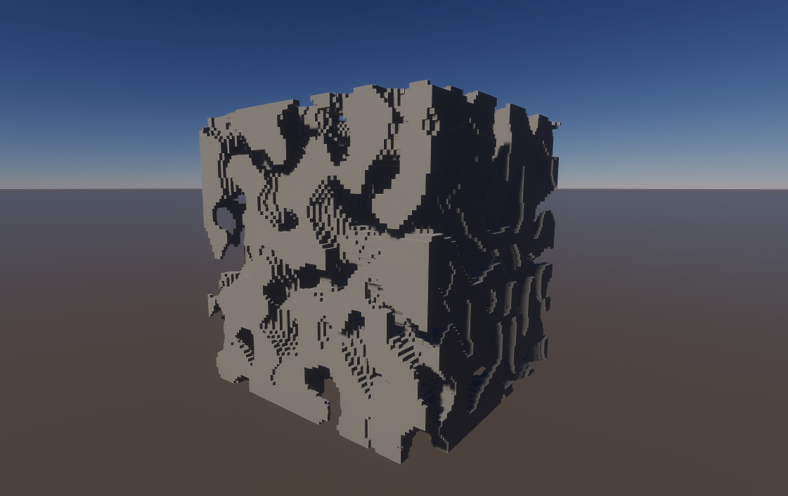
im doing minecraft like game with chunk meshes generated on GPU
so each voxel have its own UVs
im trying to do something like here
https://github.com/artnas/UnityVoxelMeshGPU
GitHub
GPU voxel mesh generation and drawing in Unity HDRP - artnas/UnityVoxelMeshGPU
What UV should cells have? If you can calculate position, then, I assume, you can generate UV also.
I do it like this
private NativeArray<half2> GetTextureUVs(int textureID)
    {
        var textureUVs = new NativeArray<half2>(4, Allocator.Temp);

        float y = textureID / TextureAtlasSize;
        var x = textureID - (y * TextureAtlasSize);

        x *= NormalizedTextureAtlas;
        y *= NormalizedTextureAtlas;

        y = 1f - y - NormalizedTextureAtlas;

        textureUVs[0] = new half2((half)x, (half)y);
        textureUVs[1] = new half2((half)x, new half(y + NormalizedTextureAtlas));
        textureUVs[2] = new half2(new half(x + NormalizedTextureAtlas), (half)y);
        textureUVs[3] = new half2(new half(x + NormalizedTextureAtlas), new half(y + NormalizedTextureAtlas));

        return textureUVs;
    }

This is not a compute shader, but ok. I don't understand why you need half (optimize later, when you will get working algorithm) but this is another question.
What exactly didn't working?
like all, i tried to test it with rendering 1 block and nothing showed
i know but i just translate my old C# code to Compute shaders, bcs i dont know how to make it other way
Im new to shaders and i dont know how to write shaders from 0 so i wanted to use this:
https://github.com/artnas/UnityVoxelMeshGPU/blob/master/Assets/Shaders/GetVertexData.hlsl
to read data from buffer and use it in shadergraph
GitHub
GPU voxel mesh generation and drawing in Unity HDRP - artnas/UnityVoxelMeshGPU
How can I sample the lightmap in a shader using URP? I'm NOT using shader graph (Code only)
Hi
I posted a question on unity forums, I dont wanna repost it as it has a video and picture
https://discussions.unity.com/t/vertex-animation-is-jittery/1499308
help would be amazing
You could use the baked GI node in shader graph and see the generated code
I'm not sure it is the source of the issue, but since you've set the texture format to be RGBAFloat, you don't need to remap and compress the normal and position values, as floating point texture can store negative value as well as value over the [0;1] range
add sin(uv.x*hScale)*vScale to your gradient
where hScale and vScale are arbitrary values to control the number of cycles of the sinewave, and the height of the wave
hScale = 12 and vScale = 0.2 should get you close to your drawing!
I fixed it
it turns out the issue was that png and tga files are saved in 8 bits ( i think this should be clearly stated in the docs)
I had to switch to exr files
Thank you!
Yes, those file formats don't support floating points, that's just in their specs, nothing Unity can do something about.
ah i see
It ended up like this (HScale: 30 and VScale 0.05)
Thank you!

Hey, could I get some help processing how I should approach an issue I've come across with my shield shader? So I wanted to add effects for when the shield gets hit that deform the vertices and I successfully did this using a sphere mask and displacing it by the vertex's normal vector. This works pretty much how I'd like it to apart from one small issue. In our game, there will likely be multiple things hitting the shield at the same time. This seems to be rather difficult to implement in the shader graph but it should be possible to pass in data as an array via a custom function node. The issue is, it's not really possible to actually iterate on this data within the shader graph although I could do this within the custom function. This was the approach I was going to take but I realize I would need to implement my own sphere mask in CG to accomplish this. I'm just starting with CG and would like to implement this if possible. How should I generally start going about an issue like this?
void SphereMask_float3(float3 Coords, float3 Center, float Radius, float Hardness, out float Out)
{
    Out = 1 - saturate((distance(Coords, Center) - Radius) / (1 - Hardness));
}
You are absolutely right that there are no loops in shader graph so only possible way is to use Custom Function. Luckily almost all the nodes has Generated Code Example in the docs so you could just yoink the code from there: https://docs.unity3d.com/Packages/com.unity.shadergraph@6.9/manual/Sphere-Mask-Node.html. I think sending the data as array/texture/buffer is the right way. You should also have a integer values that tells the Custom Function how many times you want to iterate in the for loop since HLSL arrays doesn't have a length parameter (afaik) that you could easily use in the shader
Wonderful, thank you for that info! I'm going to give it a shot
Hit me up if you face any problems with that
I have a breakdown of a forcefield shader that does ripple effects using array & loop in custom function : https://www.cyanilux.com/tutorials/forcefield-shader-breakdown/
iirc the output was used for distortion of scene color not vertex displacement. Might still be useful though
Your website is actually how I got the idea to use a custom node here to pass in my data! Thank you for the help!
Yippee! Got it working! Also zooms around the impact area. TYSM for your help Cyan and AleksiH!

not when u use compute shaders or anything that includes using buffers


I've been trying to make a Square with Smooth Outlines, however it kinda a bit Diamond Shape-ish instead, how to solve this? How to make the Color convert into grayscale without losing the alpha??

Question concerning shaders in general. Found this tweet here complaining about high vertex counts, which got me thinking.
https://fxtwitter.com/Acerola__t/status/1821746084416516322
I understand that the fragment function will only be ran equal to the number of fragments the mesh covers, decided by rasterization. Aka the apparent size of the mesh/its coverage is the deciding factor.
Is there any optimization for the vertex function? If an object is composed of 1000 verts, but only takes up a single pixel of the screen, is it still ran 1000 times? I'd assume so given you don't yet KNOW it only covers 1 pixel at this stage.

"I'm not informed on the topic I'm talking about" oh ok no need to talk about it then
Quoting 💛Jams💛 FREE PALESTINE (@JamsDX_)
im no whiz when it comes to optimization for video games so do not take my word as gospel but that strap does not need that many tris
Consider the X & Y values as two different distance fields that you need to combine. Here as some ways to do it :

Yes, the vertex stage doesn't have optimisation here, if you have 1000 verts, all are treated.
There's one called LOD which you may have heard of before. This is exactly one of the problems LOD is supposed to solve. One more thing to note here is that even if your 1000 vert object doesn't cover more than one pixel on the screen, running the fragment shader is far for free because every triangle needs to be considered separately and GPU has to always fire the whole wavefront (about 32 cores) all for the one pixel the triangle covers so small triangles on the screen are often quite heavy for the fragment state as well. (Sorry if I messed up the explanation, I'm no GPU expert but that's how I have understood it)
@steel notch Btw. Unreals Nanite is exactly that type of optimization which combines smaller tris into bigger ones on the fly but Unity doesn't have that type of dynamic LOD system built in so making multiple LODs for each mesh and using the LOD system to switch between them is the way to go
Got it, Thank You 👍
I've got some weird random behaviour with canvas shaders. Some of the ones I create are not changing at edit time when I modify properties in the material, and others do change. And I have no clue why some shader/materials can be tweaked in the editor, and why some only show changes when I hit play.
is this a shader or does the game use only flat materials?? I would like to achieve the same style, my try is in the third picture (it didnt work out xd )


what didn't work out exactly? That seems like the right direction
it seems like flat materials to me
I think it is receiving some lighting, as you can see under the slide it's darkened
aight thanks guys will continue experimenting then! maybe its because of the model quality that the game looks way higher quality
you might need to change the shader of the material to one of the unlit ones
I think it's a toon shader of some kind, which is flattening out the shading
click the shader option and change to unlit color for example

ah so I still might need a custom shader to get the exact same result?
not neccesarily custom, just click the shader list and use one that's already there
use the URP->unlit one or the unlit->color one depends if you use urp or not
yeah I use urp
But the model on the left is lit, not unlit. You can see it has shading on a few areas where the material is darkened due to lighting, it's just not a smooth gradient of shadow
then just change the shader of the material to the universal render pipeline/unlit one
is it lit, really? are you sure
it doesn't look lit to me but I don't know exactly
seems like a texture
not lighting
I guess that's possible if the model is never held at a different angle
If the gun is ever held at a dramatically different angle, then the circled areas will look odd if it's baked in

no, I just don't think it changes
the lighting on the gun
and yet I still think it's baked in
I don't think it'd look that odd, I think that's just the style
I might very much be wrong
the games name is sulfur incase u wanted to check it but I also think its just a texture based on the trailer
@mighty pivot Unlit materials would be the fastest method to try out and see if it works for you. You just need several variations per colour in spots where you want to fake darkened areas
I see aight guys thanks a lot for the help
looks like baked in unlit to me, but you could also experiment with urp/simple lit
Hello, do you know how I can apply a shader graph to a camera ?
If you mean a full screen effect, add a fullscreen pass to the URP renderer (2022.3+) and assign the material there. Use Sample Buffer to get the screen buffers (color, depth, etc) where needed
That's a lot of information all at once and I'm not sure I've understood it all 😅 , besides it's not really for my full screen but just to be able to have certain effects on my scope.

Then you apply a shader/material to the scope, and use the camera's render texture as a texture for that material. No need to touch the camera there
oh ok I think I understand ! thx for your help !
Ur welcome!
I tried to make something really basic, but I can't achive to have the little box in the inspector to put my render texture, I can just pick and select a color


That's because you only added a color?
You need a texture2D, sample it, then put the sampler into the base color.
Multiply it by a color if you want a different colored output
I suggest to look through some basic guides
oh ok I see
I already work a lot with texture in blender and I have the impression that it works the same way, except for a few details.
Is it possible to make the player's color different from the rest?


Hey everyone,
I'm using Unity 2021.3.19f1 and I need to make a shader for my UI images to change their color all at once using a single material.
I'm running into some issues, though. From what I understand, Shader Graph doesn't support UI shaders in my version. I made one using ShaderLab, but I'm struggling to get the UI images to work with components like RectMask2D.
It seems like it should be easy, but I'm stuck. Can anyone with more experience help me out?
So I make a thermal vision, but I have a problem wich is that even through wall we can see the player because he is render in top of the reste, but I don't know how to fix this issues


Maybe use the depth buffer to see if the player is behind something?
Most materials do that right?
Just edit the shared material in code
Otherwise upgrading to 2022 would get UI support yeah
I have used this as the base shader to modify and have faced no issues: https://github.com/TwoTailsGames/Unity-Built-in-Shaders/blob/master/DefaultResourcesExtra/UI/UI-Default.shader
I tried, but this can't work, because my player and my back ground are render on 2 separate cameras
you can try setting cameraclearflags to depth only on camera with higher depth
i have this color quantization shader, but it converts everything to greyscale, how can i keep the colors of the screen?
It captures the camera output, apply the shader and projects it into an Image UI.

Thank you!
when i have backface rendering enabled the back is completely black im really baffled i have spent hours googling?


I tried with both camera, and it doesn't work
hi everyone, I am working with VolumeRendering plugin from github. https://github.com/mlavik1/UnityVolumeRendering
When i launch the applicaton from Windows or Android it works fine.
But when i try it on Hololens 2, shaders are not right.
I shared both screenshots and shader code. Please help me.
First image is from hololens. Second one is from android


Does this work for HDRP too?
boost ^
It's not written with HDRP in mind but it might still work (or at least some parts of it will be the same)
Hi, I have a shader build for BRP and I want to convert it to URP. I already tried selecting it, then going Edit > Rendering > Material > Convert built-in material to URP but it didn't work
// Upgrade NOTE: replaced 'mul(UNITY_MATRIX_MVP,*)' with 'UnityObjectToClipPos(*)'

Shader "Unlit/ScreenCutoutShader"
{
    Properties
    {
        _MainTex ("Texture", 2D) = "white" {}
    }
    SubShader
    {
        Tags{ "Queue" = "Transparent" "IgnoreProjector" = "True" "RenderType" = "Transparent" }
        Lighting Off
        Cull Back
        ZWrite On
        ZTest Less

        Fog{ Mode Off }

        Pass
        {
            CGPROGRAM
            #pragma vertex vert
            #pragma fragment frag

            #include "UnityCG.cginc"

            struct appdata
            {
                float4 vertex : POSITION;
                float2 uv : TEXCOORD0;
            };

            struct v2f
            {
                //float2 uv : TEXCOORD0;
                float4 vertex : SV_POSITION;
                float4 screenPos : TEXCOORD1;
            };

            v2f vert (appdata v)
            {
                v2f o;
                o.vertex = UnityObjectToClipPos(v.vertex);
                o.screenPos = ComputeScreenPos(o.vertex);
                return o;
            }

            sampler2D _MainTex;

            fixed4 frag (v2f i) : SV_Target
            {
                i.screenPos /= i.screenPos.w;
                fixed4 col = tex2D(_MainTex, float2(i.screenPos.x, i.screenPos.y));

                return col;
            }
            ENDCG
        }
    }
}
There is no autoconversion for custom shaders.
Ok, so I need to do it myself ?
btw it doesn't show any error, it just doesn't work when applied to a material
You have to rewrite it yourself, yes.
ok thanks
anyone knows how can i achieve this effect but without a light source rather i choose where the outline will be thick and where it wont
https://lindenreidblog.com/2018/03/03/rim-highlight-in-unity/

A tutorial on how to write a shader with an outline highlight in Unity/CG.
replace this line
float3 lightDir = normalize(_WorldSpaceLightPos0.xyz);
with
float3 lightDir = normalize(_YourVectorParameter);
offcourse, you'll need to add _YourVectorParameter to your parameter
I've been trying to make a glowing texture but it seems cutout outside the texture coordinate, struggling how to prevent this happened, is this normal that outside the texture UV will be automatically stretched?


If it is outside of the texture coordinates it doesn't exist. As in, there is no data outside of that area.
So it stretched like that infinitely?
It isn't stretching. It is sampling the edge
you need padding, like give at least 1 or 2 empty pixels from edges of texture
THANK YOU!!!!
Guys i want to add a Shader that makes all the scene looks pixelated but i don't know how to do, i tried different methods but i can't figure it out. (I'm making a 2D game)
This is my game
Becaue i wanted to make the scene looks more cool i wanted to add to it a pixelated effect
Can someone guide me on how to do that pls?
I have a shader that operates like a decal, I'm using it for blob shadows and a selection ring if that character is selected. This selected property changes frequently, and I do that by setting the value from code. Will this break instancing permanently after I select a unit since the material isnt shared anymore?
You can make it a per instance value. That way batching is still good
Ty, is that an option in shader graph?
What render pipeline are you using
Urp
Then should be fine to adjust properties / use different materials. SRP Batcher can support that
Can check via the Frame Debugger window, that'll show you what is batching and drawing in separate batches
Wouldnt this feature be enabled as wel for that?
I have had some issues with shaders in the past that did not have this enabled @regal stag@hexed tulip

Shouldn't need to do that no, should be handled automatically
does anyone know why my normals show this way

Tonemapping (post process) doesn't like negative values
Use a Saturate node before outputting
for loop dont work in compute shaders?
int3 Normals[] =
{
    int3(1, 0, 0),
    int3(-1, 0, 0),
    int3(0, 1, 0),
    int3(0, -1, 0),
    int3(0, 0, 1),
    int3(0, 0, -1)
};

bool hasVoxel(int3 coord) {
    if (coord.x < 0 || coord.x >= CHUNK_SIZE ||
        coord.y < 0 || coord.y >= CHUNK_SIZE ||
        coord.z < 0 || coord.z >= CHUNK_SIZE) {
        return false;
    }

    int idx = to1D(coord);
    return uVoxels[idx] > 0;
}

[numthreads(8, 8, 8)]
void CSMain (uint3 dispatchID : SV_DispatchThreadID, uint3 groupID : SV_GroupID, uint3 groupThreadID : SV_GroupThreadID)
{
    if (groupThreadID.x == 0 && groupThreadID.y == 0 && groupThreadID.z == 0) {
        sVertexCount = 0;
        sIndexCount = 0;
    }

    AllMemoryBarrierWithGroupSync();

    uint globalVoxelIndex = to1D(dispatchID);

    if (uVoxels[globalVoxelIndex] > 0) {
        int3 coord = int3(dispatchID);

        uint vertexCount = 0;
        uint indexCount = 0;

        for (int i = 0; i < 6; i++)
        {
            int3 neighborCoord = coord + Normals[i];
            if (!hasVoxel(neighborCoord)) {
                vertexCount += 4;
                indexCount += 6;
            }
        }

        InterlockedAdd(sVertexCount, vertexCount);
        InterlockedAdd(sIndexCount, indexCount);
    }

    AllMemoryBarrierWithGroupSync();

    if (groupThreadID.x == 0 && groupThreadID.y == 0 && groupThreadID.z == 0)
    {
        uint vertexOffset = 0, indexOffset = 0;

        InterlockedAdd(uFeedback[0].vertexCount, sVertexCount, vertexOffset);
        InterlockedAdd(uFeedback[0].indexCount, sIndexCount, indexOffset);

        uint index = groupID.x + 10 * (groupID.y + 10 * groupID.z);

        uChunkFeedback[index].vertexOffset = vertexOffset;
        uChunkFeedback[index].vertexCount = sVertexCount;
        uChunkFeedback[index].indexOffset = indexOffset;
        uChunkFeedback[index].indexCount = sIndexCount;

        uIndirectArgs[0] = uFeedback[0].indexCount;
    }
}
i wanted to get rid of using if for checking every face with for loop but it seems not working,
ok i figured out that i need to add static keyword before int3 Normals[]
Can anyone recommend a good asset for handling bleedthrough skinned meshes?
"Bleedthrough"?

I don't recall seeing assets for that
Each individual mesh configuration and even a particular set of clothes might require a differenent solution so it's hard to think how a more generic asset would work
i made compute shader work with for loop but now there is stuttering, is there something wrong with my code or its just not good to use for loops in compute shaders?
https://github.com/AndrzejKebab/UnityVoxelMeshGPU/blob/master/Assets/Compute/voxelizer.compute

GitHub
GPU voxel mesh generation and drawing in Unity. Contribute to AndrzejKebab/UnityVoxelMeshGPU development by creating an account on GitHub.
Were you doing it 6 times manually unrolled before you put the for loop in?
ye before it was like 6 if statements
There’s nothing wrong with using for loops in shader code. I’m too lazy to really try to understand your code at the moment but one thing that stands out to me is the use of InterlockedAdd which may potentially be way slower than any loop
what would u suggest to do?
i tried this but it dont work

Does it fix the stuttering though?
Yes but breaks the mesh
That’s more than expected. I’ll try to figure out some alternative solution
Actually, is there some reason you are doing this mesh generation on GPU instead of multithreading on CPU to begin with? The problem in generating that type of mesh with beforehand unknown layout on GPU is that it requires making a counter which you did (and which is slow because it breaks the parallelism to some degree). One possible way to solve this would be to preprocess the chunk to a bitmap (buffer of booleans) indicating the faces that needs and doesn’t need to be added. From that bitmap you could do parallel prefix sum to figure out where to put the required faces on the vertex and index arrays. Similar method is described here (in context of frustum culling but the idea is the same): https://www.mpcvfx.com/en/news/unity-gpu-culling-experiments-part2-optimizations/. Generating this type of mesh on GPU is suboptimal as I said so if doing that on CPU is possible, it might be the preferable solution. If I remember correctly, even minecraft to this date uses only CPU for their mesh generation but I might be wrong on that. If you wanted to implement something like greedy meshing as well in the future, CPU might be more suitable for the task
why?

Can you show the declaration for the CheckIfIntersectingPlane function? It's just off screen.

You have to specify the length of the array in the function parameter. It can't take a dynamically sized array.
anyone knows how can I soft delete from an object without getting the soft delete message
You have to declare the functions you use earlier in the file. Now you are first using it and only after implementing the function. The declaration would look like this: bool CheckIfIntersectingPlane(float3 pos, float3 faceDir, float3 vertices[]);. You could also move the whole function higher up in the file so you don't need to explicitly declare it.
@vale remnant I can't find one for HLSL but this C++ document may be useful for understanding the function declaration concept if you are not used to it: https://www.tutorialspoint.com/cplusplus/cpp_functions.htm
np. moving up will work too but the declaration is the more common solution because you can have all the declaration on top but defining all the functions on the top may make your code harder to read + if functions use other functions inside them, getting them in the right order may be hard or even impossible in some cases

Is it possible to do fragment shader on shadergraph
Hey everyone, I'm trying to make it so all the billboarded sprites in my lighting shader only have one color relative to the position of the object, and not what's going on right now. i've tried many different strategies but none seem to be working

https://pastebin.com/9eAgSNLL here's my code, if anyone has any ideas or suggestions for how i could achieve this i'd appreciate it
Pastebin
Pastebin.com is the number one paste tool since 2002. Pastebin is a website where you can store text online for a set period of time.
I'm trying to recreate the appearance of some blend modes in photoshop by using the shader graph in URP, but I'm having a really hard time getting things to look identical to how they do in Photoshop. Anyone have any experience with this? Specifically trying to recreate Color Burn, which isn't accessible via the default Blend node, so I had to create a custom blend node, with this hlsl code:
void ColorBurnBlend_float(float4 Base, float4 Blend, float Opacity, out float4 Out)
{
Out = 1.0 - (1.0 - Base) / Blend;
Out = lerp(Base, Out, Opacity);
}
This is what it looks like in Unity (left) vs photoshop (right). I feel like I've tried every combination of import setting, and getting alpha from one place or another vs setting opacity on the blend node, etc, but I just can't seem to get it working.


I want to make a game similar to Minecraft, but better and more optimized, Minecraft generates chunks on CPU and is slow, that's why people make mods to improve optimization, one of them moves chunk generation to GPU using Mesh Shaders, in my game i use cubic chunks of size 32^3, and ((ViewDist * 2) + 1) ^ 3, default view dist is 8 so i generate 4913 chunks and each chunk have 32768 voxels which together gives 160 989 184 voxels, so i thought that compute shaders will be great for generating mesh as its a lot to calculate
and i tried to do already greedy meshing and i think compute shaders are easier to do than greedy meshing it sounds easy, but when I look on implementations I dont get it at all 😭
Btw. do you need to retrieve the data from the GPU back to the CPU for colliders or something like that or is it just for the rendering?
no, that would actually be wrose than using cpu, reading back from gpu is slow as... u know
I know, that's why I asked
i wanted to implement my own physics for that
Then using GPU could be fine although as I said, it's not too easy to do that in this case. If you do interlocked operations on GPU, it may end up being not much better than CPU if not worse. Afaik optimized greedy mesher is often used over GPU mesher but tbh I don't really know why that is (well, one reason might be the runtime performance being better due to more optimal triangle counts)
perhaps in the difficulty of implementation
so if i would get rid of InterlockedADD then it should be fine? what if i would make each Thread work on 1 chunk and then at the end of shader i would just merge them together 🤔
You maybe could but I'm not sure it would be very fast either because then each thread would be doing very different things inside each wavefront which is not what GPUs are designed to do either and it would likely result in memory accesses all over the places and therefore ton of cache misses. I'm by no means expert at anything I just said but that's what I think will happen
You may have to consider colorspace conversion
I think some programs apply their blends before it, some after
Thanks yeah, I suspect you are right. I tried to make them uniform, and that does seem to help, but i had trouble getting information about what to use beyond just sRGB.
Gamma to linear or vice versa
I don't know precisely when they should be applied here
Applying things before or after seems tough to account for.
Yeah, the gamma and linear are also definite possibilities. Unity has a ignore png gamma checkbox, but it didn't seem to do anything.
But yeah, would be nice to have some thorough breakdown of how this all works in both unity and photoshop
The project itself has a setting for whether it uses gamma or linear color space
The default is linear, so my guess is you might need to convert to gamma before the operation and then back to linear, or include the conversion in the burn calculation
But I have even less of an idea what color values PS is working with
Can you convert from gamma to linear and vice versa in the shader graph?
Amazing! Thank you! Will try this!
What tonemapper is your project using?
I don't know how to find that info
If you just mean gamma or linear, I'm using linear
Are you using URP or HDRP?
I tried to think of something else I could do, but nothing came to mind. Well there are also those Mesh Shaders which sound like a good solution, but Unity still doesn't support them, there is a way to use a .DLL to call it.
https://medium.com/@pushkarevmm/mesh-shaders-in-unity-with-direct-3d-12-50aaceefddb6

Medium
Mesh shading is the fundamentally new render pipeline concept. To say it simply: mesh shading is about preparing geometry for rasterizer…
BiRP: https://docs.unity3d.com/Packages/com.unity.postprocessing@3.4/manual/Color-Grading.html
URP: https://docs.unity3d.com/Packages/com.unity.render-pipelines.universal@16.0/manual/post-processing-tonemapping.html
HDRP: https://docs.unity3d.com/Packages/com.unity.render-pipelines.high-definition@16.0/manual/Post-Processing-Tonemapping.html
he probalby is talking about this

This will change how everything looks in scene and from the camera
But it shouldn't affect shader graph preview
Urp
Ah, not using tonemapping at all until I figure this part out.
Would photoshop somehow have hidden tonemapping of some kind?
I'm only comparing shader graph with photoshop. Not comparing the scene view at all
It has something like it but only for HDR images
It probably doesn't affect blending operations, but then again image editing software are extremely cryptic about that stuff specifically
that's because you are using worldPos which is the texel position in world space.
I think you should use object position instead, maybe something like
float 4 objectPosWS = mul(unity_objectToWorld, float4(0,0,0,0));
and use that in your grid function
float TileZ = IN.objectPosWS.z / 512;```Just curious, when it comes to writing hlsl shaders.
Vert / Frag where is it best to prepare UV? (panning / tiling, distortion, and such.) is it purely case to case depending on what you want to achieve or is there a reason why i see people doing it so differently?
It’s a matter of precision. If you can get away with tilling in the vert stage that is good because it is cheaper.
hmmm ok why is that?
Why is it cheaper ?
yeah
Well the vert function runs for every vertex of the mesh, the frag runs for every pixel the mesh rasterises to. Usually a mesh will have way fever verticies than pixels it occupies on the screen. So the vert function runs less times
oooooh ok now i understand. thank you
Offloading calculations to the vert stage is a common optimisation trick for shaders.
cool now i have a little optimization to do 😄 its not that the shader kills the project in any kind of way but i think i should be careful as the shader is starting to do quite a lot of UV stuff. thanks again
Again this is if you can afford the lack of precision. Tilling uv’s in the vert stage will not look the same as tilling in the frag stage.
yeah i think it should be fine. it is mostly several layers of distortion and or panning and tiling.
Why is that though? I thought linear transformation shouldn’t make a difference (which distortion isn’t) or are you talking about floating point precision?
Your tilled uv will get interpolated between the values of the 3 verts that form the triangle that the current fragment is in right?
Sure?
Well using the same value for a bunch of fragments will be less precise than calculating it fresh for each one
hello i have super weird artefact when i bake my light on this surface it's suppose to be glass shader , i don't have that when i use realtime lighting ! thank a lot


Kinda looks like that particular mesh does not have correct lightmap uv’s
What kind of transformations are we talking about? As far as I’m aware, offsets, stretching and rotations will still look exactly same due to the barycentric interpolation. Am I missing something?
the “real” fragment normals u want might not just be a linear interpolation of the vertices, i guess
so if you have some custom mapping that is more detailed than a linear interpolation
(like normal maps)
Yes, but linear transformation for all which I’m talking about and which UVs usually use doesn’t fall under that case. Many distortion effects though needs to be done in the fragment stage just for that reason
yes i would do the main distort sample effect in frag. but i think i can prepare a bit of other parts in vert like panning and tiling. i am also preparing things like uv coordinates correction (to not smear a whole texture over a Texture atlas which im using) in frag currently. which i should be able to put in vert instead.
That’s how I would do it. Usually you want to do all linear transformations (offset, rotation, scale) in the vertex shader and non linear ones in per fragment basis
i never thought of it until Uri told me that the frag runs for every pixel while vert runs for well.. verts which makes sense now that im looking it up. banger stuff 🙂
For UVs which will be transferred to the fragment shader anyway it makes sense to do as much as possible in the vertex shader but it's good to note that introducing new interpolators isn't always good idea because transferring the data between the shaders and doing the interpolation is not a free operation. Let's say you only wanted to offset the UVs by some amount but still needed the original UVs as well for the fragment shader. In that case you could make new interpolator for the offset UVs but that would more than likely be slower than just doing one vector addition per fragment in the fragment shader. In general moving calculations to the vertex shader is a good practice though
You know what I think you might be right
i started digging into hlsl about a month ago because my job needed me too, it is very fun to learn but there is so many things to learn that it is kind of overwhelming 😵
Either I'm or I have been doing things very wrong
Has anyone solved grabpass with MSAA on mobile vr platforms? Specifically OpenGL.
It causes a weird dither effect on UI elements rendered after the grabpass object. I tried using a texture 2d array multisample and using that but it had no effect at all
I’ve done a renderdoc capture that shows the texture as a regular texture array without MSAA and as a multisampled texture array with MSAA. I just can’t seem to figure out why it breaks everything over the grabpass
I can send the shader and renderdoc shader later today if that would help diagnose the issue
do these effects happen on all ui elements, do they by coincidence only happen of those that use an image mask in some kind of way?
They don’t use a mask
I believe it’s all ui elements yeah
Do you use a downsampled depth buffer?
But I believe it’s anything not captured by the grabpass
Not sure where would that be?
I don’t think I have the depth buffer enabled but I did see it mentioned in the renderdoc capture
Actually it is, I have some transparent objects rendered separately that aren’t UI and they have the same artifact
So yeah anything rendered after the grabpass
URP 14.0.9 and 16.0.2 have this line in the changelogs:
"Added workarounds for MSAA-specific visual artifacts on materials that use alpha clipping in unexpected ways."
Though i have no idea what that means and where it comes from. Maybe you can dig for details if that fits your problem.
👀
URP is mostly c# so I can just view it right?
I use BIRP but maybe it’ll help still
Good luck!
Ty for the lead I’ve been so lost
greetings shader wizards, ive never edited or created a shader before, but i have one im using with a material that is not being affected by a mask and id like it to be. is it difficult to add that into an existing one, what does it entail? this is the shader in question https://pastebin.com/T6CPpmAy
Pastebin
Pastebin.com is the number one paste tool since 2002. Pastebin is a website where you can store text online for a set period of time.
I don't understand render textures in Unity, I mean I get that I can render to a texture through the camera but that's it? I want to map the normals of all objects to a Render texture, doing it from a camera gives me one solid color for the whole texture, now I have done stuff in OpenGL so I'm assuming it's because the shader is taking in a ScreenQuad's normals? Could someone explian? Thanks!
Might want to share the details of your setup and code. It kinda sounds like you're mixing up several things.
Can I paste the code here or do I also use pastebin?
If it's more than several lines, upload it to a pastebin.
!code

Posting code
📃 Large Code Blocks
Use links to services like:
https://gdl.space/, https://paste.ofcode.org/, https://hatebin.com/, https://paste.myst.rs/, https://hastebin.com/
📃 Inline Code
Surround code with three backquotes. Not quotation marks.
To format as C#, add cs to the first line:
```cs
// Your code here
```
Add a comment with a line number if there is an error message.
At first I created a c# script that I attached to the camera just like post processing shaders that I used for edge detection. Then I changed it becuase I thought it only gave screenquad normals
But now I have another script for the same shader which takes in a shader and a render texture from teh editor, I attach the script to an object, then I want the render texture to have the normals rendered to it. But for some reason it's the same shit :/


What I am looking for!

Yes, that just gives you normals of a quad - blit just renders from a texture to a render texture. It doesn't have access to any other info, like the scene normals.
You'll need to make a draw call at the end of the queue that renders to a render texture and access the normals via a unity scene normals texture.
That being said, I'm not sure unity renders the normals to a separate texture. You might need to reconstruct them from the depth texture.
Or just render the whole scene separately with your custom shader that renders the normals.
Is it possible to have an emissive 2D shader in ShaderGraph? I want to have an emissive material controlled with a shader. I'm in URP.
In 3D shaders in ShaderGraph there's an Emission property in the Fragment node. I'm looking for an equivalent of that in 2D for sprite shaders.
If you are on forward render pipeline, you can use camera shader replacement with an unlit shader that output world space normal to color, then use a camera with render texture to get the rendered normals
If using deferred pipeline, iirc, there should be a graphic event/hook where the whole screen normal get rendered
I think unity stores like normals with the depth or osmething, i think I read it in a doc after asking this question a couple of hours ago? I guess I'll try to use that
wdym by camera shader replacement? otuput to color meaning like fixed4 frag (v2f i) : COLOR or something?
Is unity updated and using the sprite/2d shader graph?
And doesn't a 3D lit shader magically work? :p
I don't think unity stores normals with the depth, but you can calculate the normals from the depth, although it's not gonna be extremely precise. I think ddx/ddy is usualy used for that.
yeah I'm using 2022.3.20f1 version. Well I dont think 3D lit shader would be appropriate because I'm doing a lot of operations on sprites, and just part of the sprite/material I would like to emit light (which would additionally vary in time).
I might be missing something obvious though, I'm rather new to shaders.
Is blending entire materials at once possible in Unity? Something similar to material attributes in Unreal

if on HDRP, u can copy the camera normals texture to your custom RT
with a custom pass
possible in URP too i thinn
this is the easiest way imo

replacement shaders would also work
If you dont wanna do that, you could use DrawRenderers to render all objects with a single shader (your shader would just write normals) https://docs.unity3d.com/ScriptReference/Rendering.ScriptableRenderContext.DrawRenderers.html

so afaik, these are the 3 options you have
theres this, too, but i think OnRenderImage only works in built-in https://williamchyr.com/unity-shaders-depth-and-normal-textures/
Can I get the length of a Texture2DArray from a shader?
love you, you are always helping, every time i have a question about shaders, it's always you the one that comes to the rescue. Life saver ❤️
Is there any version of that also for UnityTexture2DArray?
found it! with UnityTexture2DArray.tex.GetDimensions!
Hey, I'm trying to create a raymarching shader and it seems like i'm having trouble with finding the correct ray direction (when it comes to camera movement/rotation -> see vid https://streamable.com/de0h5m) i can't figuere out whats the problem code: https://pastebin.com/2CEwMeCF
Pastebin
Pastebin.com is the number one paste tool since 2002. Pastebin is a website where you can store text online for a set period of time.
I see nothing obvious wrong in the shader itself. Is _CamToWorld something you set yourself with C# or some built-in variable?
it's being set in the renderpass execute method

I think this might be of importance so on line 21 I believe you should do -1.0. Expecting the spheres to perfectly match might be bit too much though because you don't take the field of view into account unless I'm missunderstanding what the camera space means

yeah this was the issue thanks mate
hey so why would a compute shader take 7ms longer to execute in unity editor vs a build?
everything else is the exact same, the only difference is that one is a build and one is not
And according to the unity profiler, this kernel takes 11ms
but in a build, according to nsight it takes 3ms(11ms is not a spike, its stable there)
unity editor profile vs nsight profile of the same kernel, the only difference is that one is a build(same resolutions and everything else)
I know editor is generally slower than builds
but this shouldnt extend to such a specific computeshader kenel right?


Profile editor with NSight. I am sure you will see similar numbers.
I did that too
and I saw still that one kernel taking 10ms
to be precise, the discrepancy vanishes if I stop sampling a certain array of textures(Tex2DArray it can be thought of as)
which makes me even more confused why the cost isnt very high in builds, but it is in editor
This is strange. All this executed on GPU level. Unity has almost zero influence on it. It executes API calls for draws, compiles shaders with d3d supplied shader compiler, etc. Your best bet is to carefully inspect both NSight captures. Look onto shader identity, dispatch call parameters (same grid), look at shader profiler for hot spots. I would not trust Unity with GPU profiling.
uggghhh ok thanks
builds did perform significantly better
They are, but on CPU level.
yeah
There are a lot of debug/helper/validation/editor stuff during editor execution.
This all stripped during builds.
and if I just dont run this kernel, suddenly performance is perfect in editor again
But there is nothing related to shaders.
or if I remove the texture2darray samplers
Are these textures identical between editor and build?
yes
Use shader profiling tools provided by NSight. Are you on D3D12?
yeah
Then NSight provides rich functionality for shader profiling.
yeah I use it frequently
but running it through shader profiler to see in editor, I got the 10ms for that kernel, but nothing that clearly shows why
the sampling of textures(of which if I remove completely remove the discrepancy), only said they made up 12% of the frame
not 70%
and most of the time comes from sampling textures like this
is there anything weird that may contribute to sampling an array of these being slower in a compute shader?

You'll have to lerp each PBR attribute manually in Shader Graph. If you use raw HLSL you can create a struct for material properties and a function that lerps between 2 structs.
I’ve downloaded an asset called “urp dissolve 2020” and Ive seen in the video he is using the shaders on the made objects that already has materials. I’m trying to add the same shader to my existing gameobject but it looks like it only uses the base color that the shader provides. How do I make the shader to only add the effect and not change the base color
Am I going insane ? I remember I could capture the actual game frame with renderdoc from unity. Now in 6 it just captures the actual editor rendering.
If you have editor and game windows visible, then you will got both camera renderers in one capture. Otherwise you will got only capture of window that is visible in time of a capture.
sure I make a capture with game view maximised. I do not see the draw calls for the actual scene however
just the editor
Quick question about the branch node in shadergraph. If the predicate is false do the nodes that lead into the true port get exequted anyway ?
Both sides are executed afaik
Interesting interesting
this means the speed tree shaders for urp could do with some optimisations
so it seems
that sampling textures of different formats in a row is massively slower than if they were all the same format, but only in editor? in build its massively faster? why?
so it even more seems
that its only happening in this one scene...
What do you mean sampling in a row ?
Just several samples in the shader one after the other ?
hi! this simple distortion shader only seems to work when my material is opaque. is there any way i can get it to work on transparent materials?

Is there a way to get world normals in a post processing shader? I have a simple sobel outline effect but that executes on the depth buffer and when the angle is steep enough, the pixel difference is too high enough for it to trigger the outline effect. I would like to mitigate this by comparing my camera normal to the surface normal using a dot product. How could I accomplish this? (Using post proccesing stack v2 not URP)
I think you would set the camera's depthTextureMode to DepthNormals, then sample _CameraDepthNormalsTexture. Use DecodeDepthNormal in UnityCG.cginc to decode
https://docs.unity3d.com/Manual/SL-CameraDepthTexture.html
DecodeDepthNormal doesn't appear to have an implementation in std.hlsl
Not with Scene Color node (that samples the camera's opaque texture which is always before transparents)
But you could copy the screen to your own texture after transparents using a custom feature (e.g. assuming URP, something like my BlitRendererFeature - check readme & branches for various versions)
In the shader you'd sample that using a Texture2D property with the same Reference/TextureID and untick Exposed.
But any objects that use that shader must be rendered after the blit occurs, so you'll need to put them on a layer, remove that layer from the default Transparent Layer Mask at the top of the Universal Renderer and use a RenderObjects feature to render them in the After Rendering Transparents event, with that below the other feature. I think that should force the render order
If you can't include UnityCG.cginc I would just find the decoding function(s) you need and copy them
https://github.com/TwoTailsGames/Unity-Built-in-Shaders/blob/master/CGIncludes/UnityCG.cginc
That's what I just did, thank you so much!
yeah kinda
they are all in the same array(someone got bindless working for me)
All worked great but now I am getting banding on my depth texture

is the depth texture retrieved from this just really low quality or something?
Idk I don't really use Built-in RP. Can you use that texture for normals only and still use _CameraDepthTexture for depth?
Yeah, that works, just didn't want to over sample bc sobel is already making me do 9 seperate samples so doing it for another texture just put me off
Any object (opaque or transparent) positioned in front of the distorsion would also be distorted. Is there a way to distort both opaque and transparent objects, but only if they are behind the distorsion ?
What's a good way to make a billboard that always rotates the camera, regardless of local rotation, specifically for Terrain?
Hello?
Rotates the camera? Or rotates to (face the) camera? Because in the first case it's not a billboard, unless I'm misunderstanding something.
Rotates to face the camera, sorry
While the x and z are locked
I've tried a lot of shaders online, but none worked
Either it worked but the batch count was insane, or there was a weird rendering issue
Honestly, I'd just rotate the object in C#.
I mean, I would but unfortunately these are trees on terrain


sup buddiess
Weird thing, both options work 100% correctly in the editor but for some reason, it's weird in play mode (And I'm assuming a build)
Pretty sure you can change the rotation of the trees via some terrain API.
possible to create a shader that includes a ai pretrained with my own draiwng style? just starting with shaders, trying to learn more fosho (can always retrain if necessary and redo everything from scraps)
If it is possible, how can I do this via shader?
thanks for the tips
It's probably possible via shader as well, but I'm not sure if it's possible without breaking batching/instancing. Not to mention that it's gonna be a huge headache anyway.
You can do it in C#, by modifying the tree instances array:
https://docs.unity3d.com/ScriptReference/TerrainData.SetTreeInstances.html
Not possible. Generative ai models inference is very different from normal shaders.
The best you can do is modify the textures with your model at editing time, not at runtime.
So, there is an issue with this;
- It would have to be done every frame, which can be a LOT of work for the CPU with a thousand or so trees
- It would have to be either rotated every frame, which would look really weird for close LOD (These billboards are supposed to be LOD2), or I would have to do a distance check for the LOD renderer, and then it would be evern more work for the CPU
Which is why I'm wanting it to be in the shader
Not only that, but other people could use the code (As this is supposed to be apart of a code base "engine")
Might want to try and profile it first to see just how much impact on performance that would have.
But if you really have to do it in shaders, you'd have to make sure that the shader is compatible with GPU instancing.
As for the billlboarding part itself I can see several results in Google. Might be better to use shader graph for that as it might be instancing compatible as it is.
I did find this:

Game Development Stack Exchange
I followed this guy's tutorial on making a billboard shader, and it works great, except if you are billboarding things that are tall, like a tree, it looks weird, to put it simply.
When the camera's
But this kinda rotates the billboards
It isn't 100% facing the camera in certain situations

See how some trees are rotated? I want to prevent that
It does look like most of them are not rotated towards the camera.
I don't know if it's an issue with the shader in the link, or you're doing something wrong.
Using a shader graph might make things easier.
I copied the bottom code
I don't entirely understand the math that they're doing there, so can't really say anything.
But I wonder if the initial matrix they're using is already including the rotation of the trees that unity does.
Probably
Well, in this case it's not gonna work as you expect. Maybe try researching what that code does exactly. Or try a different solution.
o.pos = mul(UNITY_MATRIX_P, mul(UNITY_MATRIX_MV, float4(0.0, 0.0, 0.0, 1.0)) + float4(v.vertex.x, v.vertex.y, 0.0, 0.0));
I did try this, but it rotated EXACTLY at the camera and also cause that weird instancing error
What instancing error?
The image on the right, when I enabled GPU instancing
You mean the black area at the top right?
Also, what's the problem with rotating EXACTLY at the camera? Do you mean like on the x/z axis as well?
hey everyone, im trying to implement a toon shader, for some reason this shader graph is not performing the "stepped" texture colors (for the shadows, you can see the final result in the main preview). Anyone see something obvious im missing?
I'm using the built in render pipeline, should i just switch to URP. I feel like everything ive been trying to do is easier in URP.

guys how do i remove or hide the standard shaders that arent URP lol

i tried googling but there are no answers somehow
im so confused
i tried finding them in the project panel but theyre not even there
wait does this mean theres no way to hide them? wtf
Yeah I'm not aware of a way to remove it, really annoying
Afaik the Main Light Direction node does not work in Built-in RP. Could pass your own light direction as a Vector3 property - set from a C# script or try reference _WorldSpaceLightPos0 which is what BiRP typically uses.
Of note, If you want to extend this toon shader further for spot/point lights that won't be possible in Shader Graph for Built-in RP as that pipeline uses multiple passes, while URP is single-pass forward. Though you could look into Custom Lighting in Surface Shaders instead of graphs.
If you do switch to URP, this package may be helpful : https://github.com/Cyanilux/URP_ShaderGraphCustomLighting
Though any other custom shaders and assets may stop working if they don't have URP versions. Be sure to back-up any projects before converting just in case you change your mind.
extremely appreciate this response, luckily i’m somewhat early in my project, so i’m going to switch to URP and I’ll take a look at those packages, thanks!
How can I prevent a shader variant from being stripped? I added it to a shader variant collection in Preloaded Shaders, but it's just complaining about it not finding it
I even tried adding a material with the exact shader and variants to a scene in the build, and it still didn't find it :|
How do you know that it's stripped?
Well, it works in editor, and in build Unity complains that:
Shader Particles/Standard Unlit, subshader 0, pass 1, stage pixel: variant PROCEDURAL_INSTANCING_ON _ALPHABLEND_ON not found.
UnityEngine.Rendering.ScriptableRenderContext:Cull(ScriptableCullingParameters&)
UnityEngine.Rendering.Universal.UniversalRenderPipeline:RenderSingleCamera(ScriptableRenderContext, CameraData&)
UnityEngine.Rendering.Universal.UniversalRenderPipeline:RenderCameraStack(ScriptableRenderContext, Camera)
UnityEngine.Rendering.Universal.UniversalRenderPipeline:Render(ScriptableRenderContext, List`1)
UnityEngine.Rendering.RenderPipelineManager:DoRenderLoop_Internal(RenderPipelineAsset, IntPtr, Object)
It could be that the target platform does not support procedural instancing
unless it's hiding some flag inside it
What platform are you building for?
Windows standalone
And we use GPU instancing for almost all our rendering and it works fine, not sure if procedural instancing is any different?
Hmm... Should be supported then.
I'd check that your quality and urp asset settings in the editor match those of the build.
Build log looks fine too

I could potentially put it in Always Loaded, but then I'd potentially get half a million variants which isn't fun
not noticing anything weird in my urp asset either
Hey so can #ifdef not stop an enclosed #pragma use_dxc from fucking up compiles on dx11?
Quick question, is it possible to output a color in a shader, so that via C#, I can set the color of the global fog to the horizon of the skybox?
Ah heck
So then is there any way to do this so I can use a #define to disable it?
    Properties
    {
        _MainTex("Main Texture", 2D) = "white" {}
        _Color ("Color", Color) = (1, 1, 1, 1)
    }

    SubShader
    {
        Tags { "RenderType"="Transparent" }
        LOD 100

        Pass
        {
            CGPROGRAM
            #pragma vertex vert
            #pragma fragment frag
            #pragma multi_compile_instancing
            #pragma multi_compile_fog
            #include "UnityCG.cginc"

            struct appdata
            {
                float2 uv : TEXCOORD0;
                float4 vertex : POSITION;
                UNITY_VERTEX_INPUT_INSTANCE_ID
            };

            struct v2f
            {
                float2 uv : TEXCOORD0;
                float4 vertex : SV_POSITION;
                UNITY_VERTEX_INPUT_INSTANCE_ID // use this to access instanced properties in the fragment shader.
                UNITY_FOG_COORDS(1)
            };

            UNITY_INSTANCING_BUFFER_START(Props)
                UNITY_DEFINE_INSTANCED_PROP(fixed4, _MainTex)
                UNITY_DEFINE_INSTANCED_PROP(fixed4, _Color)
            UNITY_INSTANCING_BUFFER_END(Props)

            v2f vert(appdata v)
            {
                v2f o;

                UNITY_SETUP_INSTANCE_ID(v);
                UNITY_TRANSFER_INSTANCE_ID(v, o);
                //o.uv = TRANSFORM_TEX(v.uv, UNITY_ACCESS_INSTANCED_PROP(Props, _MainTex));
                o.vertex = UnityObjectToClipPos(v.vertex);
                UNITY_TRANSFER_FOG(o,o.vertex);
                return o;
            }

            fixed4 frag(v2f i) : SV_Target
            {
                UNITY_SETUP_INSTANCE_ID(i);
                fixed4 color = UNITY_ACCESS_INSTANCED_PROP(Props, _Color);
                //fixed4 tex = UNITY_ACCESS_INSTANCED_PROP(Props, _MainTex);
                //fixed4 color = tex2D(tex, i.uv);
                UNITY_APPLY_FOG(i.fogCoord, color);
                return color;
            }
            ENDCG
        }
    }
}```How do I make this shader get a texture?
Wdym by "get a texture"?
So it can render a texture
I got this shader from the official unity docs, it works but only has a single color-
Because it is an instanced property, I can't get the uvs like you would normally
It does seem to have a main texture declared and samples from it.
Oh, you commented it out..?
Because it gives me an error
Shader error in 'Astro Engine/Tree Billboard': 'tex2D': no matching 2 parameter intrinsic function; Possible intrinsic functions are: tex2D(sampler2D, float2|half2|min10float2|min16float2) tex2D(sampler2D, float2|half2|min10float2|min16float2, float2|half2|min10float2|min16float2, float2|half2|min10float2|min16float2) at line 61 (on d3d11)
I actually realized my main issue, I added UNITY_DEFINE_INSTANCED_PROP(float4, _MainTex_ST) to the properties, but for some reason, it gave me the above error
I also think what is causing this error- It's a fixed4, not a sampler2d, but I wouldn't know how to get around that (If it is even possible)
Probably because _MqinTex_ST is a texture and you can't pass it into that macro.
Yeah
Well, I just want my shaders to be instanced so it can run better
Although, I don't think it's the shader that's the issue, more so Unity's terrain system
Well, the texture will have to be non instanced.
Does Unity's Terrain system allow static batching/material instancing?
Pretty sure unity uses GPU instancing for terrain trees by default already.
Though it might depend on the shaders you use on the trees.
If you're trying to optimize performance, you should probably start with profiling and investigating the bottlenecks, before attempting random solutions like writing custom shaders.
By default, the 'billboards' of my trees are just standard unlit shaders, but I'm also getting a lot of batches here (Even if they are "saved by batching", I'm getting around 70-80 FPS)
Without trees, I get 120-130 FPS

You can see why the draw calls are not batched in the frame debugger window.
Though 309 batches is really not a lot. Should be fine even for mobile imho.
Use the profiler to see what causes the fps drop.
So it seems to render a lot of trees at once, from farthest to nearest, probably because of fog


They billboards are also transparent
Read what the details say. They should provide a reason why it's not batched with the previous call.

Judging by the grouping, I'd guess that these are just different LOD levels.
Yeah, probably LOD
Yes, I'm using LOD Group to make this work
You probably have enough differences between the LOD levels that they are rendered in a separate draw call.
Lod groups are not really relevant here
Yeah
How many lod levels do you have?

Then it should be fine.
To be honest though, I'm not sure a 112 tri model needs LOD at all.
There are a TON of trees though, so
I'm trying to make this game as optimized as possible
Well, you are using GPU instancing. Which makes the tri count less of a problem.
And your current bottleneck is not even on the GPU
Yeah, it could be the CPU
It is. Judging from your screenshot with stats window.
Point is: you're doing premature optimizations without even understanding their effect. You might be making the performance worse without realizing it.
You can try that, yeah.
But what you should really do is profile the game properly. Find the bottlenecks. Then research(or ask in the community) ways to optimize them.
So uh, doing that...

Check the frame debugger to see why the calls are not batched.
Setting the tree materials to GPU Instancing added it to this, but it's still a LOT of stuff

Then you'll want to profile properly as I suggested previously.
Will do
It could be that now it's a GPU bottleneck. Profiling will tell for sure.
Going back to the billboarding, seems like this is the issue with that

But this is not a shading issue anymore- Sorry
Thanks for your help dlich
Actually are you still there? I have a unrelated shader question;
I'm trying to set the fog color of the horizon of the dynamic shader (I have modified it slightly). I was wondering if there was a way to pass the color of the horizon to a color so I can set the fog color to it, making it look nice?
Hi everyone, I try to draw tons of object by using "DrawProceduralIndirect + shader graph" in HDRP
Everything’s working fine, except the instance ID keeps returning 0
Has anyone tried this before?
Current version: Unity 2022.3.36, Shader Graeph 14.0.11
Need help😭
This is making me go nuts...
Hi, I am trying to create a shader that functions as an innerborder. In the shader graph I can perfectly adjust the width of the inner border but as soon as I apply the effects as an material on the image component the image becomes completely the color or size of the image. I will provided some pictures and gifs for clarification 😄


making a sprite outline shader, tutorial says this is supposed to move it over 1 pixel but it sure doesn't look like it is. why is this happening?

Shouldn't need the Divide unless using Width/Height ports. The Texel Width/Height is already the reciprocal
(HDRP) I'm trying to get world space coordinates in a compute shader. This shader already has view space coordinates and depth. I found "ComputeWorldSpacePosition", which requires a clip space position. However, the following doesn't appear to work:
    float4 positionCS = mul(UNITY_MATRIX_P, float4(positionVS, 1.0)); // Transform to clip space (according to StackOverflow anyway)
    float3 positionWS = ComputeWorldSpacePosition(positionCS, UNITY_MATRIX_I_VP);
The second line reads correct. I'm guessing either positionVS is not in the expected format, or the first line is incorrect.
HDRP uses camera-relative rendering which messes every standard way to get WS position up
So you probably want to use GetAbsolutePositionWS, https://docs.unity3d.com/Packages/com.unity.render-pipelines.high-definition@10.2/manual/Camera-Relative-Rendering.html
Thanks. I suspected it was that but wasn't aware of the helper function. 👍
Np, I spent a few hours last week with the exact same bug so it's fresh in mind 😅
Thanks for the resources!
hi! I followed a tutorial on youtube about dithering opacity and i want to apply it for when the camera gets closer, the opacity of it reduces... how i could do it?

Is there anyone who could help with this open standing question 😢
does anyone know why in 2021.3.16f1, the UVs are completely broken??

this is the same model and same shader just in 2021.3.5f1

Shouldn't be any difference. Check the tiling settings on the material perhaps.
its not the tiling
Maybe check the known issues section of the changelist of that version then. There might be a mention if it's a known bug.
anyone know why a fullscreen shader using blit gives me this?

ok no nvm i forgot to check Fetch Color Buffer
okay its still only affecting half the screen, is that normal??
I'd try Cull Off, might be that one of the triangles is drawn backwards
i probably should've mentioned im using shader graph,
As in the Fullscreen Graph in URP? That's mostly designed for the Blitter API iirc (which draws a triangle - not a quad). If you're using it with cmd.Blit that might be why it's not drawing correctly.
Though the graph might be generating multiple passes to support both... I'm not sure
ahh okay, i was under the impression it'd do stuff automagically. I wasn't aware I needed to write code for it
Oh are you just using Fullscreen Graph and Fullscreen Pass Renderer Feature? In that case it should just work
Use pass 0 yeah
glitch + pixellation :D

Submitted a report for that. Feel free to vote for it @harsh dagger
Reproduction steps: 1. Open the “ReproProject“ project 2. Open the “Assets/DevDunkStudio/Blur Toolkit/Sample/Scenes/Full Screen Blur...
I’m not sure if this should be in #archived-urp instead but is there some setting or something to get shaders to work on UI elements?
I’ve made a simple shader with ShaderGraph and when testing on UI, it simply flashes for a second then goes completely black
Hi! Don't know if I have to ask this in this channel, but I have a problem with render textures.
So I did my game almost entirely using objects with OnMouseDown() functions bc it's a point and click game, and used a lot of "old PlayStation" models to get that retro scary effect. And the last thing I wanted to do before publishing it was to add that iconic effect of pixelated screen that old ps games have. Every tutorial I find says to do the classical thing, render texture, raw image in the canvas and done, but the OnMouseDown functions don't work with a render texture, or at least that's what I think. Any solutions to my problem, or am I just screwed?
Don't know why I waited to finish the game to add that, and I really want that effect and hope I can get it without changing my whole code
good news! the solution here is trivial. You can just remove the graphics raycaster from your Canvas, or disable raycast target on the image you're using to display the render texture


no way it's that easy JAJAJAJ
I disabled the one on the image but not on the canvas, let me try that...
thank you a lot man! @blissful marlin
I follow Youtube tutorial video, but I don't have those shader options

they are now in Shader Graph category rather than Shader category
PBR Graph is also now the Lit Graph
You also need Shader Graph installed for those
Might be an easy question. Idk because I don't use ShaderGraph much. I'm hoping to make a shader where bullets with the material change colour depending on where they are on screen.
It kinda works, but I need to know how to stretch the effect to cover the entire screen. Preferably through an editable Vector2 that covers the area that the gradient will take up

If you want it based on the screen should use the Screen Position node instead of world space positions
Some screen position modes use ranges that start from negative, so with those you would use a Remap also to bring it to 0 to 1 range that the gradient can use
Well, those are basically the same thing for my game
It'll be relative to world space. Might need to make it only a certain area of the playfield at some point
I have a shader that creates a "pollution" effect. I want the gradient to be spread out around the entire object but it only works in certain axis, in this example the faces that point upwards are fine but the sides are not.
Anyone know how I can achieve this all around the object?


On more complex objects its even worse

Screen Position node is almost what I want but obviously if the screen moves it moves where the effect is on the object as well

Maybe look at triplanar mapping
The triplanar node works with textures, so you could use a noise texture instead of Gradient noise
Although you could also manually sample the Gradient noise on 3 different planes (XY, XZ, ZY) and blend between those, based to the normal direction
Splitting them into 3 planes I can understand but how would I do the blend using the normal direction
Something like getting a dot product for each direction vector (1,0,0 & 0,1,0 & 0,0,1) and the surface normal
Then use Absolute to make those always positive - so it doesn't just work for right/forward/up but also left/back/down
Now you have 3 values in the 0-1 range that you can use to lerp between the sampled noises
Maybe use Pow or something to control the blending "contrast"
You can find plenty of examples of triplanar shaders online
Hey guys, so polybrush is garbage and its hdrp shader doesn't support normal or mask maps for some reason
So, unusable
Also it can only blend 4 textures due to rgba
But I found this post online
Apprently, it's trivial to solve both problems but I don't speak shader graph at all and don't know what I'm doing in there
Can somebody prod me

guys how to reverse this image ?
since I'm using it on the back side of an object
1-uv.x should reverse the x coordinate
Hi there
yeah I did it last night phew
thanks tho
When using a Noise texture for UV distortion the UV for the texture i am distorting is offsetting quite a bit.
float2 distortUV = TilingAndOffset(IN.localUV.xy, _tilingandoffsetvec4, _distortionXYflowVector.xy * _Time.y);
float4 distortSample = tex2D( _distortionMap, distortUV);
_currentDistortUV = ( distortSample.rg * (_distort_power * distortMaskSample.r );
then i use _currentDistortUV to sample the Texture the is to be distorted
float2 TilingAndOffset(float2 UV, float4 Tiling, float2 Offset)
{
float2 returnUV = UV * Tiling.xy + Offset;
return returnUV + Tiling.zw;
}
is there a way to offset that well... offset?
does anyone know why my shader looks good in the editor but completely messed up ingame


im using an emission map
That _currentDistortUV is added to the UV for sampling the texture, or is it used directly ?
Usually, when doing distortion, you take the value of the "distortion texture", and add the value to the UV for sampling the main texture.
Additionally, you should remap the _currentDistortUV from 0;1 to -1;1 ( v = v *2 - 1; ) to "average" the distortion to 0
or rather its input into the sampling of the texture.
interesting will try
To sum up :
_currentDistortUV = _currentDistortUV  * 2 - 1;
_currentDistortUV += IN.localUV.xy;
float4 _mainTexSampled = tex2D( _mainTex, _currentDistortUV );
it looks the same without any post processing
thank you it worked!
Maybe texture compression ? But if editor and build are on the same platform, it should be the same also 🤔
Hello, i found some info on how to replicate the effect of vertex snapping in games for the PS1 due to hardware limitations.
The basic implementation that i have in shader graph is multiplying the vertex positions by a factor like 16 then flooring the result and then dividing by 16.
What i have now seems correct but there is an issue with the shading, on the lighter side of the object where the point light hits there is very clearly some visual glitches going on with the shading and i don't know exactly what it is caused by.
I am using Shader Graph and URP for this
Maybe it's something with the baked light but i don't think it would do that.
Looks like realtime shadow related
If you're wobbling the verts in screen space, the directional light's shadow casting pass is also wobbling the shadows in its own screen space
So the shadows will not line up with the surfaces that are casting them, but can push through
Especially since the directional light is orthographic
I would probably have to bake the directional light too then maybe?
If you have no realtime directional light shadows to cause the issue, the issue will not be there
yeah, what i also wondered. In a video someone showed how to make the effect with code and you have a specific keyword 'noperspective' that can be used and Unity would render it without perspective correction i think. I don't think it would be possible to use a shadergraph and give it the keyword somewhere
I might be confusing a totally different effect
"Noperspective" appears to be a type of interpolation from vertex stage to fragment stage, not related to vertex snapping specifically
There are many ways to do vertex snapping though, some involving perspective
If you snap them in world space without utilizing any perspective at all, then the shadows should line up
But baked lighting can't suffer from the problem in any case
Yeah, i am going to look for more resources to see what everyone does to get those retro effects
There are many different ones
Most probably avoid this by not using realtime shadows, since the old games didn't have this type of shadows if any
Yeah, i still need to figure how i style my game so i will experiment with various techniques
Can anyone explain how i can recreate LinearEyeDepth() in shader graph?
"inline float LinearEyeDepth( float z )
{
return 1.0 / (_ZBufferParams.z * z + _ZBufferParams.w);
}"
Ive got the below but im not getting the expected results

how do you get the world space position from the depth texture?
would this get the world position ?

Hello, i found this video talking about how to achieve the affine texture warping effect in Unity with shaders.
I am using shader graph and found a post saying someone achieved something like that with the custom interpolator.
I am not sure though how the interpolator exactly works and how to convert the code to shader graph so it's the same.
https://www.youtube.com/watch?v=Tbe2niFQI2M
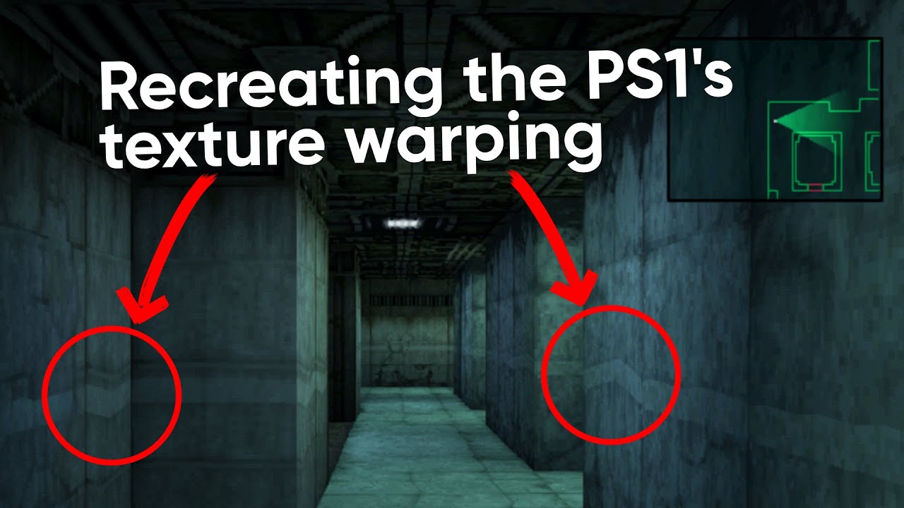
The PlayStation 1 was many people's first console, but games on the system were plagued by strange graphical artifacts. One of these is called affine texture warping, which causes wall and floor textures to appear wobbly. In this tutorial, we'll look at how the modern graphics pipeline avoids this effect, then remove those features to get our ow...
I think these points would all be at the screen center, just at different depths.
I usually use this method : https://www.cyanilux.com/tutorials/depth/#mesh-perspective
(or section below for orthographic)
If it's for a Fullscreen Graph, just use the Position node - it handles depth reconstruction for you
I have some info on custom interpolators here, if it helps
https://www.cyanilux.com/tutorials/intro-to-shader-graph/#custom-interpolators
And I believe positionCS.w is equivalent to the Screen Position node set to Raw -> Split A
Though possibly only for the vertex stage one.
(It might just be 1 in the fragment so unsure if the / positionCS.w is needed...?)
Thanks, i will try and see if the screen position can be used for that
I think i have it
you are probably correct
this is what i put into the interpolator

this is what i have as the input for the sampletexture part

this is the result, it seems similar to what the video showed

Anyone know why my CustomDepthPass below would be causing these weird unity ui artifacts, even when the game isnt running?

My pass
how can I make it so a number increases when switched is true, and decreases when its false?

i cant use sine time because its not guaranteed that itll start from 0 when switched becomes true
i did
i cant make it so the float goes back into the add
it wont allow
yeah, so chances are what you want is not possoble, since its maintaining state over time in the shader
shaders do not really maintain any state between invocations
well then wtf am i meant to do lmao
what are you trying to accomplish?


so this is the shader on the windows?
maybe I could do it using code?
just adjsut a float property over time in code
the windows dont matter
I basically want to transition smoothly between 2 materials in a way
thats what I was thinking yeah
I could do some workarounds though
float property feed it into T of a lerp
adjust that property in code
so like you cant maintain state in a shader, even if you could the sahder is literally running parts of it per vertex and parts per fragement per frame
also how can you get a HDR property field?


yeah should be fine
if time is 0, use texture
if time is 1, use solid
thank you!
ill try to quickly figure the code out
do you want it set globally
shouldnt be hard
or per mateiral
globally yeah
thera are 2 ways of doing it
hmm i saw this last night couldn't understand the math behind using screen position's alpha channel some how dividing that by the view direction in world space helps convert depth to world. unintuitive
select your property in the graph @ionic python so you can see its real reference name which is what you use with this method
oh yeah I know that
i think the SetGlobalFloat should work, i know it does for a regular no shader graph shader
but if not you might need to do it with the same function on each material
@ionic python actually
do this on your prop

The screenPos.w/positionCS.w just happens to be the depth to the pixel being rendered due to how the projection matrix works
But if it helps you can replace that with the Position node set to View space -> Split B or Swizzle "Z" -> Absolute or Negate
The divide is kinda similar to normalising the View Vector (but in terms of depth, not a unit distance), so multiplying by the scene depth then gives you a vector to that scene point.
hold up, I don't have this

nvm sorry
override hides it
Ive been messing around with text based shader for a couple days and found something on making grass (https://www.youtube.com/watch?v=MeyW_aYE82s). I was messing around with there shader in unity and wanted to add shadows to it. In the video they recommended reading this on how to make the shadow pass https://www.cyanilux.com/tutorials/urp-shader-code/#simple-lighting. However I cant get it to work. Additionally if I add the shader to a plane then try to move the plane it moves the grass more than the plane which I cant seem to find the reason for. (Forgot to add the shader can be found by going to the first video lookin gat its description going into the git page then assets shaders)


Breath of the Wild's grass is visually striking and helps to break up large areas of ground. In this tutorial, learn how to make stylised grass just like it in Unity URP using geometry and tessellation shaders!
👇 Download the project on GitHub: https://github.com/daniel-ilett/shaders-botw-grass
✨ Roystan Grass Shader: h...
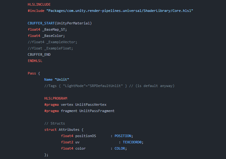
Explains how shader code (ShaderLab & HLSL) is written to support the Universal RP
to make it global enable the override
yeah i forgot to
tho its still not working
ah i see. interesting! thanks for the info
This will break SRP Batching compatiblity. If you want a global variable (set by Shader.SetFloat), just untick the Exposed tickbox.
You mostly only need to use Override Property Declaration for global matrices
ah good note, i am not as familar with shader graph as just writing thigns myself
where all you do is not define it in the shaderlab part for this
@ionic python look at cyan's comment
and you are using the reference name and not the name?
yeah
i copied it out
something happens here though

why is it in neon mode if the default value is 0?


at 0 it should be in normal mode
i would set it at start up through code
just on awake somewhere set it 0
yea but i cant see what the normal textures are like in scene view
and changing the combatTime does nothing
yeah so when its not exposed the defualt means nothing
you pretty much need code to explicty set it
whats the default value when its not exposed?
either way you will need code to explicty set it to what you need
if you need to do that in editor as well as playmode would write a edtior script, or do it in the on validate of a script
@strange basalt <3
ill need to tweak it a bit
plus I need a way to spice up the overall environment
Does anyone have a functional shader for polybrush in hdrp?
pls guys I'm losing my mind
I need help, as you can see, the small cars inside the shop (3D models inside of canvas), won't fade in/out with the rest of the canvas group, is there a way to apply a custom shader to them to change their transparency and set it to the alpha value of the canvas group?
a cool effect would to to sphere mask it from the center, so the effects grows outwards from 1 point, just grow the radius of the sphere mask over time
no way to effect it from the cavnas group since they are not rendered as part of the canvas
you got 2 options, adjust the alpha on the material for the cars at the same time
or
shader?
render them to a render texture with a other off screen camera
then just display that render texture in the UI
That's a good idea
But idk how to do that lol