#archived-shaders
1 messages · Page 81 of 1
when i set something to legacy shader it stops rendering pink
one problem is i cant switch default to legacy(in inspector)
before

after

@civic lantern i have a bit of fixing of problem-i need legacy shaders
You need legacy shaders? I thought you have them
yes i need to set everything from buggy default to legacy
Not sure if you can change the default shader/material, but you can search for that
like this one

There's no clean way to expose a generic gradient. If you settle on a black and white gradient with 4 control points max, sure, it fits into a float4. But a colored gradient with 16 control points each storing a float4? Nah. Can't even have a serializable float4 array material property for it.
Well, uvs in a quad usually go from xy 0 0 to 1 1. If you use that vector as a color(rgba) it ends up as the preview of the node. Shader graph shows the output of the node like that to make it easier for you to understand what outputs it would provide in the shader.
are material property blocks generally a bad idea with the newer pipelines versus just making a new material instance?
i need each object to have different colours so i can either instance a material or use property blocks but not sure which one is better for performance
It's more specifically about whether you're using the SRP Batcher. That is incompatible with material property blocks and wants you to use material instances instead. The SRP Batcher is optional on SRPs, enabled by default.
any idea as to why my outline shader isn't working? im following this tutorial: https://www.youtube.com/watch?v=VGIkT9fPh7Y, however the outline just isn't rendering. attached are images of the sphere, its inspector, and the shader itself. (if you need better images of the shader lmk)


In this video I show how to create an inverted hull shader for model outlines using shader graph in Unity 3D for URP.
#gamedev #unity #unity3d #shadergraph #unitytutorial #unitytutorialforbeginners #unitytutorials
here's a (hopefully) better image of the graph

You're using world space normals and position where the tutorial is using object space.
that was it! thanks for the help. I always seem to miss the small details lol
i see
didnt think about that. why wouldnta float 4 array work?
anyone know why i get two very different results when subtracting these two similar nodes from the same node?

its like thats not really black
Maybe try saturating before connecting to the subtract node?
Yeah, it's likely negative values. - -1 = +1
@ebon moss
I was wondering if its possible to make a shader like the background in balatro.
Its some sort of procedural screensaver that seamlessly animates and change shapes and colors.
Does this sort of thing has a specific name? I don't even known what to look for...

The general name is noise. The specific effect is probably several layers of perlin noise twisted and perhaps stepped.
wym with stepped?
Using the step function
btw here's another example

oh its an actual function, thanks for the info, I'll study that
The emphasis is on layered perlin noise.
This one is probably quite a bit simpler than the first screenshot
I remembered the exact name of the technique. It's called domain warping.
wow I tought the opposite
but I get it, balatro one is more subtle so I guess it takes more to refine that noise
Here's some more info https://github.com/dandrino/terrain-erosion-3-ways
yeah this one is somewhat it https://iquilezles.org/articles/warp/ (take from doc you posted)
Articles on computer graphics, math and art
This one is probably just a 3D noise function, using time for the z axis. Then additional math to convert to lines (i.e. multiply then sine or frac)
Shader "Unlit/Timer"
{
    Properties
    {
        _MainTex ("Texture", 2D) = "white" {}
        _Color ("Color", Color) = (0.0, 0.0, 0.0, 1.0)
        _Angle ("Angle", float) = 0.0
    }
    SubShader
    {
        Tags {"Queue"="Transparent" "IgnoreProjector"="True" "RenderType"="Transparent"}
        ZWrite Off
        Blend SrcAlpha OneMinusSrcAlpha
        Cull front
        LOD 100

        Pass
        {
            CGPROGRAM
            #pragma vertex vert
            #pragma fragment frag
            // make fog work
            #pragma multi_compile_fog

            #include "UnityCG.cginc"

            struct appdata
            {
                float4 vertex : POSITION;
                float2 uv : TEXCOORD0;
            };

            struct v2f
            {
                float2 uv : TEXCOORD0;
                UNITY_FOG_COORDS(1)
                float4 vertex : SV_POSITION;
            };

            sampler2D _MainTex;
            float4 _MainTex_ST;
            float _Angle;
            fixed4 _Color;

            v2f vert (appdata v)
            {
                v2f o;
                o.vertex = UnityObjectToClipPos(v.vertex);
                o.uv = TRANSFORM_TEX(v.uv, _MainTex);

                return o;
            }

            fixed4 frag (v2f i) : SV_Target
            {
                fixed4 col = fixed4(0.0,0.0,0.0,1.0);
                fixed2 uv = i.uv;
                fixed2 center = fixed2(0.5f, 0.5f);
                fixed sqrDistance = pow(center.x - uv.x,2)+pow(center.y-uv.y,2);
                float angle = atan2(uv.x - 0.5f, uv.y-0.5f);
                if (sqrDistance < pow(.5f, 2) && degrees(angle)+180 < _Angle){
                    col = _Color;
                }
                return col;
            }

            ENDCG
        }
    }
}
im tryiing to make a circular progress bar but it doesnt show up at all
finally fixed it
I have this nodes to split into shades. How i can manually app/down at one shade?

I don't understand the "app/down at one shade" part 🤔
I already did it, I meant shifting the shading by one step
You either shift the input or output of the posterize nodes by 1/number of steps
Trying to make a basic shader in URP that colors an object black if it's in shadow, and white if not. The best way to do this it seems is by sampling the main directional light shadow map (I don't care about additional lights at this point in time) but I can only just draw the shadowmap on the object like what would usually happen (see screenshot)
I think I need to get the center of the object and feed that into the ShadowAtten function but I'm not sure how.
Code:
real ShadowAtten(real3 worldPosition)
{
    return MainLightRealtimeShadow(TransformWorldToShadowCoord(worldPosition));
}

half4 UnlitPassFragment(Varyings IN) : SV_Target {
    real atten = ShadowAtten(IN.positionWS);
    return  atten;
}

I've tried using unity_ObjectToWorld, which according to a few forum posts I could find, should give me a point at the object's center but it didn't work.
This is what my fragment shader code looks like with those changes:
half4 UnlitPassFragment(Varyings IN) : SV_Target {
    float4 objectOrigin = mul(unity_ObjectToWorld, float4(0.0,0.0,0.0,1.0) );
    real atten = ShadowAtten(objectOrigin);
    half4 baseMap = SAMPLE_TEXTURE2D(_BaseMap, sampler_BaseMap, IN.uv);
    return  atten;
}
https://forum.unity.com/threads/get-object-center-in-a-shader.180516/ this is the forum post I found
Unity Forum
Hello! I have some issues about getting the object and the camera coordinates inside the shader.
So, camera center command suppose to be...
_Object2World doesn't exist anymore and was changed to unity_ObjectToWorld
I also tried putting it into the vertex shader since running matrix multiplication on all pixels is probably a bad idea. Here's what that looks like (irrelevant code omitted)
struct Attributes {
    float4 positionOS    : POSITION;
    float2 uv            : TEXCOORD0;
    float4 color        : COLOR;
};

struct Varyings {
    float4 positionCS     : SV_POSITION;
    float3 center       : TEXCOORD1;
    float2 uv            : TEXCOORD0;
    float4 color        : COLOR;
};

// Vertex Shader
Varyings UnlitPassVertex(Attributes IN) {
    Varyings OUT;

    VertexPositionInputs positionInputs = GetVertexPositionInputs(IN.positionOS.xyz);
    OUT.positionCS = positionInputs.positionCS;

    // Or :
    //OUT.positionCS = TransformObjectToHClip(IN.positionOS.xyz);
    OUT.uv = TRANSFORM_TEX(IN.uv, _BaseMap);
    OUT.color = IN.color;
    OUT.center = unity_ObjectToWorld[3];
    return OUT;
}
and then I just use center as the argument for the ShadowAtten function
but it still doesn't work. Object just becomes pure white and doesn't change even if it's fully in shadow
Does anyone know what I'm doing wrong?
also not sure if I mentioned it, but incase it wasn't already obvious, I'm using the URP
I've also tried using the source from the Object Node in shadergraph
GetAbsolutePositionWS(UNITY_MATRIX_M._m03_m13_m23)
but that also doesn't seem to work
Is the object being static batched? (As that would ruin the model matrix)
Object is just a non-static cube

There's one good example by Fabrice Neyret on Shadertoy which you could tear apart if you're interested
don't have GPU instancing enabled either

Ah, turning off shadowcasting and using GetAbsoluteWorldPosition worked
Final vertex and fragment shader if anyone is interested:
Varyings UnlitPassVertex(Attributes IN) {
    Varyings OUT;

    VertexPositionInputs positionInputs = GetVertexPositionInputs(IN.positionOS.xyz);
    OUT.positionCS = positionInputs.positionCS;

    OUT.uv = TRANSFORM_TEX(IN.uv, _BaseMap);
    OUT.color = IN.color;
    OUT.center = GetAbsolutePositionWS(UNITY_MATRIX_M._m03_m13_m23);
    return OUT;
}

real ShadowAtten(real3 worldPosition)
{
    return MainLightRealtimeShadow(TransformWorldToShadowCoord(worldPosition));
}

// Fragment Shader
half4 UnlitPassFragment(Varyings IN) : SV_Target {
    real atten = ShadowAtten(IN.center);
    half4 baseMap = SAMPLE_TEXTURE2D(_BaseMap, sampler_BaseMap, IN.uv);
    return  atten;
}
@tidal forge what threshold and strength values are you using on your outline material? Even using your outline shader I can't seem to replicate your effect, which makes me think it's something to do with the textures. But my textures seem to be accurate. Though the way you're sampling them doesn't work for me, it just produces a pure black or pure white texture. I have to use SAMPLE_TEXTURE2D to get working normal and depth textures.
are you referring to this?
https://www.shadertoy.com/view/ldfczS

these are textures using a 30mb image 8192x4096. Why does Unity memory profiler show that the Texture2D size is 170mb? Where does the rest come from?

mipmaps maybe?
- Graphic size is "uncompressed" I think
Can we have a step by step guide on how to upgrade shader graph's to make it work with GPU resident drawer?
i disabled mipmaps and it dropped to 128mb native size
8Kx4K RGBA32 is exactly 128mb size

multilying by 1.33333 (all mips take 33% of original texture) = 170mb
it's a png on my computer but only 30mb

Exactly as I suggested
I'm guessing it's compressed then
Size on disk != GPU size
GPU cannot work with jpg, png, and many other formats
Only hardware compatible compression formats can be used. You can specify it here:

As a result you will get one of block compression formats:

hey guys! can i make a procedural effect like this in shadergraph where i can change the length of the lines, the number of the lines and their width?
this is from substance painter


yes
Look for the different shape nodes in shadergraph, The "rectangle" one will help draw the lines.
The tricky part will be to to a radial repetition, it's basically rotating the UVs, but in "steps"
Let me doodle something up quickly, it will be easier than to figure it out with words
Here's the very simplest graph I could think of to make this shape :

See how the rectangle node results change with the UVs transformation.
You might want to read about distance functions to draw 2D shapes with shaders : https://iquilezles.org/articles/distfunctions2d/
Articles on computer graphics, math and art
thank you!
ill try it out
I've also done lines like this, which with a bit of masking with circles (steps on R output) could produce a similar result

Haha, I was trying to figure out something that didn't involve rotation ^^
I didn't want to dive into SDF for the first example 😅
This setup definitely seems like it could be useful for other shapes too though... might steal it for an example on my polar coords post 😁
Hey guys! Ive been having trouble finding resources for grass shaders with billboarding effect that help cover an entire plane, much like this picture. Any documentation or known guides would super cool, thanks 😄

@vague imp And an other more complete example, more based on Cyan's one, and some math from IQ website :e


To cover the plane usign only shader, that's how it can be done : https://www.patreon.com/posts/geometry-grass-47447321
Or you have to instance meshes yourself

Either you have a shader that does mapping based on the vertices positions, or you have bad UVs I think
When using Branch On Input Connection, how do you connect a property to the Input field?

Position is a property of the subgraph, not the 'Position' node, btw

i mean you went through all this effort already so can i get the .shadergraph file pleaseeee?
🙏 Thank you sooo much 😄
i used the model and same shader in an older unity version and it worked fine

thats what its meant to be like
the material looks fine here but then it isn't even visible on the model

here 🙂
thank you 🙏 🙏
Under the Node Settings you need to enable the "Use Custom Binding"
For more info/example see : https://www.cyanilux.com/tutorials/intro-to-shader-graph/#sub-graph-branch
Can you show the material inspector ? Maybe the tiling setting just broke when upgrading

Thanks!
I put the material on a cube and it looks normal?

Maybe something in the shadergraph ? .... can you show it ?
This is the image texture^^^

if I add 100 of those to the scene, how does that consume memory compared to if there was only one of that texture in the scene?
is it just going to reference the same memory for all of them? And it's only when the GPU has to render the textures that it affects performance, right?
It won't consume more memory. But having 100 of them will cost more in rendering, as more objects have to be drawn, over more pixels
makes sense, thanks
How i can make something like that, but not depending at camera view? Clouds shadow it's just 2d noise
Anyone know how I can change shaders based off of the x, y and z coordinates of verticies? I am trying to make the top of this shader connect to the bottom parts. It is going to go inside of a fish tank, and the wavy top is the surface


Should be able to use the same displacement, but along Vector3 of (0, 1, 0) instead of Normal Vector.
Sample the noise in world space instead (or Absolute World for HDRP)
How can I do this? this is my first time using the shader graph
Replace the Normal Vector node in the graph screenshot with a Vector3 node, with Y set to 1. Then the same graph (or a different graph with same nodes in vertex stage) should work for both planes
For some reason looks correct only in this way

Yea, if you want to map a 2D texture from above you need to use X and Z axis. So split or swizzle nodes work for reordering the vector components
should I just send you it cause the shadergraph is too big to get in 1 image
Hi guys. Does any of you have references for working with terrainMaterials, I want to make a biome system with TerrainLayers
You can. The most interesting bit here though would be how the UVs are applied to the sampled texture
here
couldn't send the shadergraph on its own for some odd reason
heres the model as well cause its messed up mostly on this
Hum, looks good to me ?

it worked fine on the previous version of unity I used but on the newer one is where im running into this problem
Does anyone have any ideas for why the crosshair's alpha renders as white instead of being transparent? I'm trying to make a crosshair that inverts colors behind it. I'm quite new to shaders so any help is greatly appreciated! Here's the shader code:
Shader "Custom/Invert" {
    Properties
        {
            _Color ("Tint Color", Color) = (1,1,1,1)
            _MainTex("Main Texture", 2D) = "white"{}
        }
        SubShader
        {
            Tags { "Queue"="Transparent" }
            Pass
            {
               ZWrite On
               ColorMask 0
            }

            Pass
            {

                Blend SrcAlpha OneMinusSrcAlpha
                Blend OneMinusDstColor OneMinusSrcAlpha
                BlendOp Add

                SetTexture [_MainTex]
                {
                    constantColor [_Color]
                    combine texture * constant
                }
            }

         }//end subshader
}//end shader

top one is the messed up one and the bottom one is the one where its fine

I'm on 6000.0.5f1, can hardly be newer
- I think you'd need to use alpha cutoff to discard transparent pixels.
- SetTexture is quite an old semantic, you should instead use regular vertex / fragment functions, see the vertex/fragment shader example sections of the doc
Okay thank you!
tryingt to make a depth-fade effect where objects become more transparent the closer they are to another object but it's bugging out and I don't know why

this is the subgraph I'm using pulled straight fro a youtube video

(yes, distance is set to something higher than 0)
Shouldn't you use the B value of the screen position node ?
Using the A output should be correct (assuming perspective camera) as the projection matrix causes it to contain the eye space depth to the fragment
Surface Type on graph should also be Transparent
That setup is pretty common for intersection effects (like water foam and fog planes), though I tend to reconstruct the world position and dot product with normal as I find it more accurate. Could try that, see example 2 here : https://www.cyanilux.com/tutorials/fog-plane-shader-breakdown/

Also looks like camera might be rendering to a low res texture or downsampled? I'd wonder if that could be interfering?
I have a couple of questions about optimization. As we can see, transparencies really hurt fps, how can this be fixed? Will a simple model work more efficiently?
And also a question about GPU instancing, now I instancing grass all over the mesh, if I instancing grass only in the visible space, will it increase fps?
And also a question, why does the frame time on the CPU increase if all the changes are only in shaders?


Oh, unitys plane it's not just two tris...

Unity also has a quad ^^
I'm surprised by the stats, I don't really get why when using transparency it takes more time ton the CPU 🤔
I think it's probably just counting the time waiting for the GPU to finish.
It looks like you don't need alpha blending in this scene. Alpha cutout would be enough. You can gain a lot of performance that way. Alpha blending requires drawing everything back-to-front, which maximizes overdraw. Alpha cutout, on the other hand, can write to the depth buffer and be drawn front-to-back, minimizing or even eliminating overdraw.
if I instancing grass only in the visible space, will it increase fps?
If you're GPU bound, you should gain some performance. But it might not be much. The only time you'll save there is the time spent running the vertex shader on all the unseen grass instances. The fragment shader will not run in both cases, and the fragment shader is likely heavier than the vertex shader.
Depends on your render resolution.
50% of native
When i changed plane to quad seems like transperent works even faster
This is because when it is opaque it draws grass in normal, that doubles batches
(in shadowmap)
What?
When rendering opaques, by default, they are also rendered in the shadowmap. That doubles (or more) their draw calls
Maybe I don't understand something, but my grass doesn't cast shadows. I checked the frame debugger, there the grass is rendered specifically to normal, which is then used for outlining
Oh, ok, I didn't have that context.
How i can know in shadergraph that shader executes not in actual play mode?
i have a specific type of grass that i want and multiple people mentioned this project. however im on hdrp and when it comes to shaders, im a total noob. if anyone has experience, is this something that is convertable and if so, would it be doable by someone that has never worked with shaders before in the timeframe of a week?

GitHub
Contribute to cainrademan/Unity-Grass development by creating an account on GitHub.
What do you mean ? You would like to know if the shader is not on any visible object ?
I just wanna disable clouds shadows in scene view
You can't do that out of the box.
You could write some c# script that sets a global shader variable like _IsSceneView and branch in the shader based on this.
The script would update the variable from the RenderPipelineManager.beginCamera callback.
It seems very optimistic to me that a shader beginer would be able to adapt this in a week.
sad, guess i have to find another way to make fitting grass
heya, anyone got any idea what the float2x2 equivalent is in c# inside a struct?
this is the struct in hlsl```
struct Box
{
float2x2 m;
};
You can use a Vector4 for that if you like. Anything that has four floats in it, like float2x2 has. If you have the Unity.Mathematics package, you can also use the float2x2 type from there. All of this achieves the same thing, just packaged differently on the C# side.
okie thx alot! wasnt sure if i could use the mathematics package with shaders
I think you can do something similar, because there are sources and guides there. And i am new to shaders too and learn all this stuff - very fun
id love to get more indepth with shaders, and i eventually will. but atleast for this project i have time constraints and i cant sacrifice more than a week and maaaybe 1 or 2 days extra for grass and foliage
Are you following this guide? https://gist.github.com/ArieLeo/d7e6bc5485caa9ba99cd3a59d0f53404

Gist
DrawMeshInstancedIndirect with ShaderGraph and URP - Usage.cs
If so, it's probably the grass spawning script that's slow
It's pushing data to the GPU even when the instances don't change. You can fix this by changing the List of draw data to an ObservableCollection and then binding PushDrawData to ObservableCollection.CollectionChanged
so List<DrawData> becomes
ObservableCollection<DrawData> instances;
on initialization inside start or awake or whatever, you can do
instances = new ObservableCollection<DrawData>();
instances.CollectionChanged += (s, e) => {
    if (e.Action == System.Collections.Specialized.NotifyCollectionChangedAction.Add)
    {
        PushDrawData();
    }
};
and also make sure you call .ToList() when setting the compute buffer
drawDataBuffer.SetData(instances.ToList());
I just find random vertices in Start() so it doesn't get calculated every time
    {
        MaterialPropertyBlock propertyBlock = new MaterialPropertyBlock();

        propertyBlock.SetVectorArray("_Normals", normals);
        propertyBlock.SetVectorArray("_WorldPositions", worldPositions);

        Graphics.DrawMeshInstanced(
            planeToInstantiate.GetComponent<MeshFilter>().sharedMesh,
            0,
            material,
            matrices,
            instanceCount,
            propertyBlock,
            UnityEngine.Rendering.ShadowCastingMode.Off,
            true,
            3
        );
    }```

Ahd then thisaight
I need help on something similar:
https://gist.github.com/ArieLeo/d7e6bc5485caa9ba99cd3a59d0f53404 I'm following this guide on using shadergraph with Graphics.DrawMeshInstance and I want to add my own data to the DrawData struct. Namely, I have a variable that controls what index in the atlas I'm using for grass the shader should use. I want to control this from the spawning script (randomly set the index) since doing it from shaders is annoying (randomness on the GPU is a PITA)
Gist
DrawMeshInstancedIndirect with ShaderGraph and URP - Usage.cs
struct DrawData {
    float3 position;
    float4 rotation;
    float3 scale;
};
DrawData looks like this. You can see how it's used in the Gist
What is the difference between Inderect and a regular function?
Just add another variable/type to the struct on both sides and access it in shader via the same way (via _DrawData[instanceID].variableName)
👍 thanks
Someknow example of custom terrain shader with layers?
When creating a ui element that uses the material of a shader, the shader is black in game but the correct color in the editor and graph
If you're in 2023.2+ use the "Canvas" graph type
Older versions don't have proper UI support but see https://www.cyanilux.com/faq/#sg-ui
I’m on a version around 2021, and could you go more into detail on how I could fix this? Thank you
@tidal forge how are you projecting the cloud shadows onto the scene? is it just a calculation in the shader of every object blending the noise with the object color?
I’ll read this once I get better . I’m surprised that these are even sending lol
In short, use Screenspace-Camera mode on the Cavnas, not Screenspace-Overlay
I tried this. Then my ui began rendering behind all of my game elements?
Change the plane distance. Or use a second camera to render the UI
Alright, I’ll mess around with it and see if I can fix it. Also is it possible for you to explain why this occurred?
I would like to be able to avoid any future issues of this type
(New to UI and trynna learn things 🙂)
For some reason with Screenspace-Overlay, Unity tries to render all passes in the shader. There's shadowcasters and depthonly passes that graphs generate intended for 3D objects which doesn't play nicely.
Hm. So you’re telling me screenspace overlay is somehow attempting to cast a shadow onto my UI because it thinks that it’s a 3D object?
Not really. It's just rendering passes that it shouldn't
https://www.youtube.com/watch?v=_uxV9R3JrXo
for creating cloud shadows, what does he mean by ```
- A purely screenspace approach looks great, but does not behave consistently when the camera perspective changes
- A purely worldspace approach is stable to camera rotation, but looks artistically inconsistent, and betrays the core 3D engine when the shadows roll over the edge of any object.
The solution is a clever mix of the two approaches, by building a worldspace formulation which assumes the world is a flat relief, and blending it with the physically correct worldspace formulation. The method is similar in spirit to normal smoothing in toon shaders for shading character faces in anime-styled rendering.```
how does it mix screenspace and worldspace?
I think it's overkill for pixelshaded style. Clouds it's just 2d noise and later apply to shader.

Just mix mainlight shadow with this tex
inside the shader of every object in the scene?
Yep
how do you even get shadow attenuation in shader graph?
i only know shadowAttenuation = MainLightRealtimeShadow(input.shadowCoord);
@regal stag has a good example in its repository
oh nice i'll check it out, i think i found it
Well
I can immediately tell you what keywords are needed for lighting, they were unclear to me


Global MultiCompile for each
i've never even seen node settings be changeable in shader graph so i should probably download the github repo to see
It's so frustrating that you need download shadergraphs to see, may be I will make simple web site for displaying shadergraps later
shader graph definitely muddied the waters of unity shader examples
oh i see it's a Keyword property. never used one before
The first picture is at a position the object shows. The second picture is me slightly backing up my camera. For some reason this shader causes the objects to only show at certain camera angles/positions. Why is that?


its depth test mode is set to GEqual. I feel that this should always render it, not only at specific camera angles/positions.
It seems to either behave like that in all the unity versions i have installed, or just not work at all in some of them (rends like normal). I thought I had an understanding of depth testing, but I guess not. So what is going on?
The order the objects are rendering in might be changing as you change the camera angle. Usually with ztesting you adjust render queues / sorting priority on the material to make sure it renders after regular opaques
I mean usually in code it's the Queue tag, but shader graph doesn't expose that so has to be done on the material
how would the order change? If the order changed then wouldnt objects behind other objects randomly appear in front of things they shouldn't be in front of?
Render order is based on distance between object origins and camera. For opaque queue, it renders nearest first to reduce overdraw. But they write to depth buffer, so objects further away (using ZTest LEqual) still won't appear on top
ok but what about this green object, which is further away than the white cube, using GEqual?
If they use the same queue at some camera angles the green might be closer to the camera than the white cube and try to render first
Frame Debugger window would show the render order
https://www.youtube.com/watch?v=4IUp1iJBqGw this guy has an explanation of cloud shadows for 3D pixel art games

I hope you enjoyed sharing this journey with me of exploring volumetric lights and simulating cloud shadows on the screen.
I don’t know if this approach is standard or not, but I think it looks good and it runs very well, which is the most important thing for me.
If you like the way this effect looks like and you want to achieve the same effec...
cloud explanation starts at 1:09
i ve been following a tutorial for a wind foliage shader but ive come across a small issue, it works like intended when the camera is still, but once it moves, it goes crazy. its in hdrp, anyone know what i did wrong?


World space in HDRP is camera-relative
Absolute world space is for that purpose instead
so i just need to replace every world space with that? thx
now i have another problem, for some reason, i can look through the branches and see whats behind them. why is that?


and how can i manipulate the shadows that they atleast remotely look like treebranches with leaves
hello o/, regarding POM in shader graph, there's no depth on the material ( I'm sorry, I'm new to shader graphs). I'm using URP, Unity 2021.3.38f1.

Hey everyone, how do I make a URP skybox shader that contributes to environment lighting the same way a standard skybox does?
Standard skybox:

My shader:

URP shadergraph output doesn't support depth offset
ohhh that's why! Thank you!
What type of shader / shadergraph did you do ?

Hum, I tried this and it worked.
What does it looks like if you check in an isolated scene, without dynamic light and a single white rough sphere ?
Trying to use SampleMainLightCookie but I get this error. Yes, I have the correct keyword defined.
this is the line that's erroring
#if defined(_LIGHT_COOKIES)
real3 cookieColor = SampleMainLightCookie(positionWS);
light.color *= cookieColor;
#endif
Looks like you're not colling the function properly, check the function definition in the Custom_Lighting.hlsl file
Or, if this is the line of the .hlsl file, search for the SampleMainLightCookie declaration in other include files (included in custom lighting file ?)
That's how it's supposed to be called.
Well, that's not what the error says

GitHub
Some custom lighting functions/sub-graphs for Shader Graph, Universal Render Pipeline - Cyanilux/URP_ShaderGraphCustomLighting
@harsh marsh oh thanks. also while that guy and other similar examples are doing 'real' god rays, this guy https://youtu.be/sQf1z8dFcao said he is just doing 2d planes aligned with the sun direction which is probably a lot cheaper and still looks really good. Potentially better since it's not 'perfect'
What maintexture and maincolor means and why i can tag property?
Why it's even maded?
https://github.com/Unity-Technologies/Graphics/blob/a83ee1ff63a0700144665f69b583bfd1ef5c3966/Packages/com.unity.render-pipelines.universal/ShaderLibrary/LightCookie/LightCookie.hlsl#L71 this is what the source code says

GitHub
Unity Graphics - Including Scriptable Render Pipeline - Unity-Technologies/Graphics
I don't know what else to tell you
it only takes a single float3 argument
Tried SampleMainLightCookie(positionWS.xyz) ?
positionWS is a float3
It's supposed to bind a color and a texture to the Material.color and Material.mainTexture api properties
I'm out of ideas
yeah i think im just gonna wait until I have some money and just buy the critter environment addon
For what did you wanna use cookie?
3 weeks ago the guy in that godot 4 pixel town video said he was going to release a demo soon. though who knows how 'soon' soon is
For shadows like in critter env?
and who knows if demo means sample project or just an executable
I want to do everything that was done in Critter Environment myself and I have a couple more ideas. It's seams not so hard
By the way, I have already done what Critter Environment does not have
My pixelart slightly smoothed out, which solves problems when the lines are crooked

And I don't use render to texture, it sounds kind of crooked in general
i was considering not rendering to low res texture, but the performance gains of doing pixel calculations on 640x360 instead of max resolution seemed too good
I'm still not rendering at full resolution
oh, how
In URP you can simply specify the render scale...
oh you're using the render scale in the asset
i was using that originally but then i read some forum post about it not being good
but i can't remember why
I thinks it's better than rendering in texture anyway
but it may have been true in like 2020 but isn't true anymore
ya the benefits are nice for like a non 1.7778 aspect ratio monitor
it was a bit tricky to integrate a custom upscale shader into URP but i managedIt's was little bit hard
Well, i am using 21:9 for example, so yeas
Again, I don't think that the render scale is somehow crooked in Unity, because there is support for FSR, even if it's the first one, and you can't do without FSR now
I'm in Gamma color space. Maybe it has something to do with that? Anyways, its not a high priority for me. I'll just use the default skybox shader for now. Thanks for trying it out!
I was ready to patch the urp so that it would work, but then after thinking I decided that render scale would be suitable
ya i'll probably revisit render scale down the line
it is annoying having to deal with multiple cameras
Now i know how to make this custom inspector!

Using the depth map for intersection effects. When I'm rendering to a lower resolution and upscaling, it causes the intersection effect to become misaligned
How can I avoid this?
it also causes water reflections that use the render output of another camera to become misaligned too

I assume I have to do something with the camera node's width and height but I'm not sure what
anyone?
@tidal forge is there any particular reason you opted not to go for the directional light cookie solution for cloud shadows?
where will you recommend to learn shaders in unity?
Hey everyone!
I'm trying to migrate my project to from DX11 to DX12 and I'm getting some shader compilation errors, can somebody help me understand what is going wrong and how I could fix it? The shader seems to work just fine in the scene view and in even in play mode though, looks to me like its getting hung up on some new raytracing requirement even though that is not even enabled in my project.
Compiling Subshader: 1, Pass: GBufferDXR, RayTracing program with DIRLIGHTMAP_COMBINED LIGHTMAP_ON MINIMAL_GBUFFER STEREO_INSTANCING_ON _DISABLE_SSR_TRANSPARENT
Platform defines: SHADER_API_DESKTOP UNITY_ENABLE_DETAIL_NORMALMAP UNITY_ENABLE_REFLECTION_BUFFERS UNITY_LIGHTMAP_FULL_HDR UNITY_LIGHT_PROBE_PROXY_VOLUME UNITY_PBS_USE_BRDF1 UNITY_SPECCUBE_BLENDING UNITY_SPECCUBE_BOX_PROJECTION UNITY_USE_DITHER_MASK_FOR_ALPHABLENDED_SHADOWS
Disabled keywords: DEBUG_DISPLAY DYNAMICLIGHTMAP_ON PROBE_VOLUMES_L1 PROBE_VOLUMES_L2 SHADER_API_GLES30 UNITY_ASTC_NORMALMAP_ENCODING UNITY_COLORSPACE_GAMMA UNITY_FRAMEBUFFER_FETCH_AVAILABLE UNITY_HARDWARE_TIER1 UNITY_HARDWARE_TIER2 UNITY_HARDWARE_TIER3 UNITY_LIGHTMAP_DLDR_ENCODING UNITY_LIGHTMAP_RGBM_ENCODING UNITY_METAL_SHADOWS_USE_POINT_FILTERING UNITY_NO_DXT5nm UNITY_NO_SCREENSPACE_SHADOWS UNITY_PBS_USE_BRDF2 UNITY_PBS_USE_BRDF3 UNITY_PRETRANSFORM_TO_DISPLAY_ORIENTATION UNITY_UNIFIED_SHADER_PRECISION_MODEL UNITY_VIRTUAL_TEXTURING _ADD_PRECOMPUTED_VELOCITY _DISABLE_DECALS _DISABLE_SSR _DOUBLESIDED_ON _MATERIAL_FEATURE_ANISOTROPY _MATERIAL_FEATURE_IRIDESCENCE _MATERIAL_FEATURE_SPECULAR_COLOR _MATERIAL_FEATURE_SUBSURFACE_SCATTERING _MATERIAL_FEATURE_TRANSMISSION _REFRACTION_PLANE _REFRACTION_SPHERE _REFRACTION_THIN _SURFACE_TYPE_TRANSPARENT _TRANSPARENT_WRITES_MOTION_VEC```Light cookie uses texture, but shadows it's noise
Does anyone know? (please click message im replying to in order to see screenshots)
How i can make this in custom ShaderGUI?

I'd probably see how URP handles it - https://github.com/Unity-Technologies/Graphics/blob/master/Packages/com.unity.render-pipelines.universal/Editor/ShaderGUI/BaseShaderGUI.cs (specifically DrawAdvancedOptions function)
Could even use that class as a base for your shader gui
only thing I can think of trying is scaling screen position based on the resolution scaling factor (if I'm rendering at quarter resolution (0.25), then the screen position is scaled 4x)

but it doesn't work
I'm also using orthographic project if that changes anything
The screen pos is 0-1 across the screen so it shouldn't really need scaling afaik.
I guess it depends if the texture you intend to sample is still "full resolution" but actually only rendering into a quarter of it. If that's the case might be Multiply by 4 instead of Divide? Not sure.
In this example it's dividing 1 by 0.25
which is 4
so it's already multiplying it by 4
@tidal forge you can use a Custom RenderTexture Asset and assign a material with noise to it and apply that to the light cookie. It doesn't have to be a traditional texture
but it comes with its own issues
I initially thought I would use light cookies, but then I used this method and it's very simple. Well, for example, the scene can be infinitely large (for example), and the texture has a limited size. If we were to render it into a texture, then we would need to move it along with the camera (which, in general, doesn't sound that difficult), but why, if you can do it easier?
still absolutely no idea how to solve this btw
@tidal forge how do you solve the situation where you have an object covered by the shadow of a large object moving above it. The object should temporarily stop receiving cloud shadows until the object above it moves away.
Just make the shadows from the clouds weaker than from other objects.
but what if the object beneath is lit by another light source. the cloud shadows would still appear
You're just doing the shadows and lighting wrong, that's the problem. You need to light the shadow anyway, and since the shadow from the objects is stronger, the shadow from the clouds won't appear.
oh right multiplying by mainlight light or shadow attenuation should clear it, or something like that
I'm writing custom shaders for a VRChat prefab called VRSL. I'm getting some weird stuff on the edges of my models and I'm not sure what of my shader code is causing this.


Shader "VRSL/Custom/JDC1_Base"
{
    Properties
    {
        [Header(Base Properties)]
        _MainTex ("Albedo (RGB)", 2D) = "white" {}
        _MetallicSmoothness ("Metallic(R) / Smoothness(A) Map", 2D) = "white" {}
        _NormalMap ("Normal Map", 2D) = "white" {}
    }
    SubShader
    {
        Tags { "RenderType"="Opaque" }
        LOD 200

        CGPROGRAM
        // Physically based Standard lighting model, and enable shadows on all light types
        #pragma surface surf StandardDefaultGI
        #include "UnityPBSLighting.cginc"
        #define VRSL_DMX
        #define VRSL_SURFACE

        // Use shader model 3.0 target, to get nicer looking lighting
        #pragma target 3.5
        struct Input
        {
            float2 uv_MainTex;
            float2 uv_NormalMap;
            float2 uv_MetallicSmoothness;
        };

        #include "./Packages/com.acchosen.vr-stage-lighting/Runtime/Shaders/Shared/VRSL-Defines.cginc"
        half _CurveBeam, _CurvePlate;
        #include "./Packages/com.acchosen.vr-stage-lighting/Runtime/Shaders/Shared/VRSL-DMXFunctions.cginc"
        //#include "Packages/com.acchosen.vr-stage-lighting/Runtime/Shaders/VRSLDMX.cginc"
        #include "./JDC1-Functions.cginc"

        sampler2D _NormalMap, _MetallicSmoothness;

        inline half4 LightingStandardDefaultGI(SurfaceOutputStandard s, half3 viewDir, UnityGI gi)
        {
            return LightingStandard(s, viewDir, gi);
        }
        inline void LightingStandardDefaultGI_GI(SurfaceOutputStandard s, UnityGIInput data, inout UnityGI gi)
        {
            LightingStandard_GI(s, data, gi);
        }

        void surf (Input IN, inout SurfaceOutputStandard o)
        {


            // Albedo comes from a texture tinted by color
            fixed4 c = tex2D (_MainTex, IN.uv_MainTex);
            fixed4 ms = tex2D (_MetallicSmoothness, IN.uv_MetallicSmoothness);

            o.Albedo = c.rgb;
            // Metallic and smoothness come from slider variables
            o.Metallic = _Metallic * ms.r;
            o.Smoothness = _Glossiness * ms.a;
            o.Alpha = c.a;
            o.Normal = UnpackNormal (tex2D (_NormalMap, IN.uv_NormalMap));
        }
        ENDCG
    }
    FallBack "Diffuse"
}``` This is the code for one of the materials used on the modelDoes it depend on your smoothness or metallicity?
Commenting out the lines for metallic and smoothness didn't seem to fix it

yo, how can I fix these "Cannot Resolve" errors in my hlsl file? they cause my shader not to work if I include this file, even though shader graph loads it just fine as a custom function
with an "unrecognized identifier 'Light'" error
presumably the other can't resolve errors would give the same if I fixed Light's
I believe it's because I need the urp lighting includes, but those throw a cannot open source file error
        #include "Packages/com.unity.render-pipelines.universal/ShaderLibrary/Core.hlsl"
        #include "Packages/com.unity.render-pipelines.universal/ShaderLibrary/Lighting.hlsl"
i wanna learn about shaders .
Check out the pinned resources on this channel. There’s a lot of resources to get you started
is there like a workflow I can follow for a difficult shader idea? I found this artist Kan Liu and really want to mimic their artstyle of water in a shader but I have no idea where to even start
Do you have access to their code?
it's artwork I want to base this shader on. here's 2 examples of their work


The droplets? Or the surface water?
It looks relatively realistic, so maybe look up a shader for realistic water droplets first. Then you can adjust it to your preferences

I have a probelm: my shader material works only with sprites, becouse when i apply it to an image and rotate, it doesn't follow the rotation

If it uses UV coordinates, then rotating the image will cause the pattern to rotate as well
If this is only going to be used on "Screen Space - Overlay" canvases, you can use the "Screen Position" node in the shader graph instead of UVs
that'll make the shader look like a window that lets you see the pattern through it
Its using this:

Oh, I see
I got your problem backwards
Replace that position node with a UV node
On a canvas, the Object position will actually be the canvas's object-space position
I was dealing with this (near-)exact problem a few days ago
But that causes stretching...

Screen space distortion of some sort?
What that means? And another trouble, i found that URP Lit have different NdotL (i modifed shader code), but i can't figure out why i have a different result, i understand that it's most likely because of getting light direction, but i'm still racking my brain for quite some time now
At example pix right looks for me better and it's URP shader


I think so, but the refraction is also very painterly so maybe an effect after that. I'll look into screen space distortion though
any suggestions for a text editor for .shader? I use visual studio but as far as I can see it doesn't support shader and there's no addons that add support. There are some shader addons but they add minimal support at best(I'm not even sure they work)


I've noticed that I'm spending way longer compiling shaders for my Linux build than for my Windows or macOS builds. I have an HDRP project with some Lit and StackLit (ouch) shader graphs.
does that support shaderlab or is hlsl close enough for it to be compatible enough?
It's not a showstopper, but I'm curious about why it's happening..
Allot of extensions

awesome thanks I'll check it out
Yep, probably also means you don't have to be too exact with the distortion
hi
I want this kind of look
https://www.youtube.com/watch?v=n7P-6R3okjU
How can I make this in Unity?
Could you provide some resources for the same?

Good luck on your edits !
BCC Ripple Effect Preset: https://mega.nz/file/HnpywBwb#yepVP_nmK5GmnSH0RW8aqkyTJnF-vur0gXRrfF31lfg
My socials:
Carrd: https://chipsexample.carrd.co
Tiktok: https://www.tiktok.com/@chipsexample
Instagram: https://www.instagram.com/chipsexample/
kofi: https://ko-fi.com/chipsexample
Tags (ignore)
after effects tutori...
the resources I find online, related to shaders, are quite old... and the options are not at the same place...
*sigh*
I guess if I don't actually ask for help, I won't get it. I'm just not good at asking for help.
Anyway this is for built-in renderer because it's for a legacy project where switching render pipelines would break all the content.
Here's my shader. It seems to change depending on the rotation of the object.
I rotate the root object and the lighting changes.
Here's how the scene is set up

here's how things differ at 180 degrees rotated... They should be the same because the light, mesh, and camera are all parented to the root and only the root is being rotated, and the scene isn't playing so there's no chance of any monobehaviours changing the orientation of anything (there are no monobehaviours but just saying it woudn't matter)


and here's the shader in question
the math all seems to more or less work fine, it's just dependent on rotation for some reason... Also note that the scene has a pure black sky box, ambient is set to color as pure black color so as to eliminate any chance of confounding factors
here's a package with the full source... built with 2022.3.22f1
This looks a bit weird to me. Line 99.
float3 worldNormal = normalize(mul((float3x3) unity_WorldToObject, normalTex));
I don't see the vertex normal being take into account here. The normal texture is just converted directly into world space.
I think this, combined with static or dynamic batching, could be the reason it's not working.
Static and dynamic batching will combine meshes and zeros out all rotation, baking them into the vertices instead.
I really don't think batching is the issue here because the tests I'm doing are done in a way that even if batching were being done, it shouldn't be interfering. There isn't a vertex normal being taken into account because I don't know how to do that. This is literally my first attempt at writing a shader.
How can you be so sure that batching shouldn't be interfering if this is your first attempt at writing a shader? How can you know how batching will affect shaders?
because this is the entirety of the scene

the only thing being rotated is root
if batching were being done, then all meshes being batched would be rotating in the same way anyway
the test is designed to isolate the rotation issue I'm having
But like I said, batching gets rid of all rotation and bakes it directly in the mesh. That means unity_ObjectToWorld will have no rotation anymore.
You can try disabling batching in the shader by adding "DisableBatching" = "True" to your Tags
i'm disabling it in the engine real quick because it's the way I know how to do that
still happens with these settings, going to try the tag

still happens with the tag
Try using IN.worldNormal instead of calculating it yourself. The surface shader has already calculated it for you.
float3 worldNormal = IN.worldNormal; //normalize(mul((float3x3) unity_WorldToObject, normalTex));
Still happens with it set like this
something else going on here... there's a mask being applied that lerps between StandardSpecular and the retroreflective calculation... and where the mask is completely black to have it be StandardSpecular, the problem still persists
and it's driving me up the wall
heck, it happens if I set the shader on the material to StandardSpecular
wait nm on that, I changed the wrong material
made an all new material in case something was stuck in the metadata... now i can't get the bug to replicate
...
and now an entirely different bug is back that I had previously squashed... position of the root now matters...
I can't even see worldNormal being used, there's definitely some weirdness with the normal calculations here. I assume the textures are in tangent space as that's what surf shaders expect.
Perhaps what you want is to set o.Normal to a combined normal map, then call WorldNormalVector(IN, o.Normal) to transform it to world space for use in the CalculateRetroreflectiveLighting function?
I wouldn't know if they're in tangent space or not... this is literally my first attempt at coding a shader...
Ask me to code anything in C# and I've got it done and working flawlessly in no time... but shaders are something I know next to nothing about
I'm probably going about this all wrong
the shader I've written is a great proof of concept, but... everything about it needs to be reworked from the ground up and I'm close to the point of tears now
Hi chat, what do you guys recommend me to study to achieve this effect in Unity ?

😍 Vẻ đẹp của Neon Dream - AUG khi đạt cấp độ 10 - Bạn đã sở hữu siêu phẩm này chưa?
➡ Chi tiết bản CẬP NHẬT 22.2 xem tại: https://bit.ly/vn-update-22-2
1⃣. VŨ KHÍ MỚI: FAMAS - Khẩu súng trường tấn công Pháp này sẽ xuất hiện trong hòm thính thay cho AUG.
2⃣. CÂN BẰNG VŨ KHÍ:
- AUG chính thức ra khỏi Hòm Cứu Trợ và có mặt trên tất cả các bản đ...
if you mean the arrow and glowing neon sticker effects, these are pretty standard texture offsets over time, you should learn this relatively quickly after picking up on shader basics
there's more to that, I think. The dots are looking like they're acually running on a grid. It's not just a texture scrolling.
Where can I find an HLSL implementation of FFT? I've been searching on Google but with no tangible results.
I can't help you with this, but I'm curious: what do you need it for? Waves?
https://github.com/greje656/PhysicallyBasedLensFlare/blob/master/Lens/fft.hlsl does this one not work for you?

GitHub
Lens flare. Contribute to greje656/PhysicallyBasedLensFlare development by creating an account on GitHub.
I'm currently creating an ocean waves simulation
This is what I have right now but this is working on the CPU and is running at 50 fps.-
I'm aiming for offloading parallel tasks onto the GPU and tile the ocean to dynamically adjust the resolution of nearby tiles
My FFT implementation uses for loops but I was trying to avoid this using xy compute shaders.
I'm also using various dispatches on the CPU to avoid the 3rd last inner loop
Very interesting. This is way above my head, but this talk https://www.goldenssuisse.net/?_=%2Fslideshow%2Fan-introduction-to-realistic-ocean-rendering-through-fft-fabio-suriano-codemotion-rome-2017%2F74458025%23KJWqMdlUlBn8PPpbQxHpg47mcIByHhGvrvc%3D seems to be about what you're after. There's an email address at the very bottom of the slides. Might be able to reach out and try that. Just in case nobody answers here 🙂
If I learned one thing in uni it's that you can actually just shoot experts an email and many actually respond and are happy to help!

SlideShare
An introduction to Realistic Ocean Rendering through FFT - Fabio Suriano - Codemotion Rome 2017 - Download as a PDF or view online for free
actual presentation: https://www.youtube.com/watch?v=ClW3fo94KR4

[BETTER AUDIO RE-UPLOAD] A widely used approach to displaying realistic FFT (Fast Fourier Transform) ocean water in today's games is presented. A similar approach has been employed in movies like Titanic and Waterworld and in games like Assassin's Creed 3 and Crysis just to name a few. In this presentation we will talk about the matematical aspe...
I have no idea how to even use that shader.
Maybe you can ask him directly: https://twitter.com/greje656 it's worth a shot. He even has a blogpost about water stuff https://www.jpgrenier.org/riverrenderer.html and works at Unity.
"If I learned one thing in uni it's that you can actually just shoot experts an email and many actually respond and are happy to help!"
If that doesn't work, can I use a 9mm?
I'll give it a whack. Thanks for your help.
On Fabio, me or yourself? no
Depends on how many errors I get
I want to make an array of blinking lights that all flash at different intervals. I've simplified it here with 5 planes using 1 material. Is there a way to individually control how it looks on each plane, or do I need to create 4 duplicate materials?

At my previous place of employment us artists would just hand it off to software and they knew how to do it. I regret not asking them how it worked 
hang on a sec, I have something
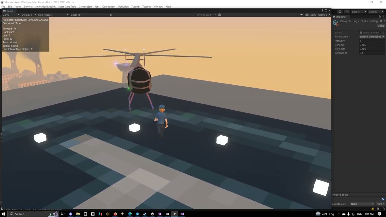
So I wasn't happy with how once I enabled bloom, the white blinky lights were brighter than the red, green, and blue ones, or how yellow was dimmer than white but brighter than red, green, or blue.
So I wrote a couple of functions to apply the luminance model to make the lights appear brighter or dimmer based on their color and how human eyes pe...
Ok. Holding on.
everything is being done with just one material per color, each color is one shared material, and the code is changing the shared material
the lights are, however, all generated at runtime, because the project is loading and reinterpreting SimCopter meshes from the original SimCopter game files at runtime.
Which is also why they're all flashing at the same time because it's how SimCopter did it.
Anyway, point is... as long as you're using the same material across all lights, and you want them to be syncronized, you can just edit the shared material at runtime without having to edit each individual object's material
for different intervals though
Man, I really need to learn how to code.
for different intervals, you need to be controlling them all differently
I figured out how to set this lil guy up, but I'm struggling to figure out how to add an emissive field next

I don't know what the correct "code word" would be
um, hang on
Okay.
In the meantime this is what I have so far, and lines 10 and 22 are wrong according to the console.

first, the shader needs to have emissive enabled
Alright, done.
and then it's like
material.SetColor("_EmissionColor", color);
it might be _EmissiveColor instead of _EmissionColor I can't remember off the top of my head
Ok, so where would I stick that in this script?
you'd set it in the Update, let me grab the code I'm using in the above video real quick
appreciate it!
I can rebuld an engine and CAD parts down to a thousandth of an inch, but code is a new frontier for me. hahaha!
    void Start()
    {
        StartCoroutine(MyCoroutine());
    }

    // Coroutine that performs an action, then waits based on the public float
    IEnumerator MyCoroutine()
    {
        while (true)
        {
            foreach (Material mat in MAX.blinkyLights.Values)
            {
                switch(blinky.filterMode)
                {
                    case BlinkySettings.FilterMode.None:
                        mat.SetColor("_EmissionColor", mat.GetColor("_BaseColor") * blinky.intensity);
                        break;
                    case BlinkySettings.FilterMode.Luminance:
                        mat.SetColor("_EmissionColor", AdjustLuminance(mat.GetColor("_BaseColor")) * blinky.intensity);
                        break;
                    case BlinkySettings.FilterMode.NormalLuminance:
                        mat.SetColor("_EmissionColor", NormalizeColor(mat.GetColor("_BaseColor")) * blinky.intensity);
                        break;
                }
                Texture currentTexture = mat.mainTexture;
                mat.mainTexture = null; // Temporarily unset the texture
                mat.mainTexture = currentTexture; // Reassign the texture

                // Optionally, if changing emissive properties
                mat.EnableKeyword("_EMISSION");
            }
            // Wait for the duration specified by the public float
            yield return new WaitForSeconds(blinky.timeOn);

            foreach (Material mat in MAX.blinkyLights.Values)
            {
                mat.SetColor("_EmissionColor", Color.black);
                Texture currentTexture = mat.mainTexture;
                mat.mainTexture = null; // Temporarily unset the texture
                mat.mainTexture = currentTexture; // Reassign the texture

                // Optionally, if changing emissive properties
                mat.EnableKeyword("_EMISSION");
            }
            // Wait for the duration specified by the public float
            yield return new WaitForSeconds(blinky.timeOff);
        }
}```it's a little more complex than what you need
simpler version would be
    void Start()
    {
        StartCoroutine(MyCoroutine());
    }

    // Coroutine that performs an action, then waits based on the public float
    IEnumerator MyCoroutine()
    {
        while (true)
        {
            foreach (Material mat in MAX.blinkyLights.Values)
            {
                mat.SetColor("_EmissionColor", mat.GetColor("_BaseColor") * blinky.intensity);
                Texture currentTexture = mat.mainTexture;
                mat.mainTexture = null; // Temporarily unset the texture
                mat.mainTexture = currentTexture; // Reassign the texture

                // Optionally, if changing emissive properties
                mat.EnableKeyword("_EMISSION");
            }
            // Wait for the duration specified by the public float
            yield return new WaitForSeconds(blinky.timeOn);

            foreach (Material mat in MAX.blinkyLights.Values)
            {
                mat.SetColor("_EmissionColor", Color.black);
                Texture currentTexture = mat.mainTexture;
                mat.mainTexture = null; // Temporarily unset the texture
                mat.mainTexture = currentTexture; // Reassign the texture

                // Optionally, if changing emissive properties
                mat.EnableKeyword("_EMISSION");
            }
            // Wait for the duration specified by the public float
            yield return new WaitForSeconds(blinky.timeOff);
        }
}```the blinky.timeOn and blinky.timeOff are just float values that specify how long the light should remain on or off
there's no reason to have it running in an update function, which would just eat up some cpu every frame that it's not changing the state of a light
the reason for the texture switch is before FOR SOME STUPID REASON it won't update the emissive property unless I do that
I'll see it blinking in the material, but unless the texture is changed, it never gets updated in the scene
Okay, time for a dumb question: How do I fix these lil guys?

you're going to have to integrate that into a proper script for yourself
I didn't give you the full script, just the relevant code I'm using
Oooooooh, gotcha
there's a bunchof stuff not in the scope, like the object named blinky, which is a scriptable object
and that requires that you go and add make new assets and everything... i just provide the code there as a kind of pseudocode to show you how the logic flow works
For a noob like me, this is gonna take some dissecting, but seeing how it works gives me a jumping board to start off on
Thanks a bunch for the examples!
I recommend taking a class in programming... doesn't have to be C#, the basic idea is just to learn how to program in general, picking up C# from there is just a matter of syntax
but if you can take a class in C# that'd be even better
I got started with a class in GWBASIC back in the 90s
I was just a kid
and GWBASIC was already ancient back then
At the rate I want to go, I keep eyeballing some bootcamps to get a grasp on things. So many time I've wanted to do complicated tech art only to be pointed to Github, and I just lock up.
community college class on programming, way better than a bootcamp
it's generally a few hundred dollars per course... not super cheap, but very affordable
I'll take note of that. Cash would be my limiting factor then.
Taking a year plus off working the industry puts a dent in the vacation funds.
assuming you're in America, and haven't gotten a pell grant already, a pell grant would probably pay for it
and you come out of it with a CS degree with actual transferable credits should you want to seek better education
community college is the single most underrated higher education in America
I did for my first round of college a decade ago. Compsci degree, specialized in game art, hard surface models in particular. Also got a course director's award for 2D animation which was neat.
awesome
The most code I did was back when Flash was still the coolest thing on the block.
2009, take me back
I've forgotten everything I learned in that by now
It was basic DVD menu style commands, but hey it worked
well to make games you're going to need to learn loops and flow control... and of course trigonometry won't hurt
I'd love to re-learn that now that I have a use case for it. I was doing well in High school, then on my tail end of 11th grade and all of 12th I hit a wall of "how is any of this practical" and just scraped by on the finish line.
Then half a year ago I saw Acerola's video on how the back end of layer styles works in Photoshop showing the curve graphs and the math behind them and had a "oh... that's the practical use" moment.
well, the professor in the community college I went to who was teaching BASIC, every single lesson was full of practical use for the code he was teaching
does anyone know what i can add here to make the texture transparent? even if the texture im using is transparent, it doesnt apply it.

Does "alpha" ring any bells?
no not really im basically almost new to this shader stuff
Well, alpha determines the transparency of the object. You want to plug the texture alpha in the fragment shader alpha input.
it worked thanks so much
does thronefall use a special shader that gives it its unique look? or how is it achieved

I haven't played the game, but looks like either using a 3 step color ramp texture on every model or a simple light calculation that is stepped. Then add an outline to it. Not sure if it's the same shader, but the trees might have a different one that gives that spikey shadow look.
thank you!
is there a way to gradually change a material's emission from black to white?
because right now i can only set the color

Lerp the color.
A color is just 3/4 floats
thanks
I am trying to write a shader to fade between the color of objects in my scene and the skybox color based on distance from the camera, but my distance calculation method is not working. It is returning all 1, resulting in the objects being invisible because only the skybox color is being shown. Does anyone know how I could fix this? https://paste.ofcode.org/GmNB7J5gQULwRT7aAcpsNq
I am very inexperienced with shaders so it may be a dumb mistake but I have no idea what is going wrong here
Does anyone know why this pass doesnt render anything?
#pragma require geometry

#pragma vertex gs_vert
#pragma geometry gs_geom
#pragma fragment gs_frag

struct Attributes
{
    float4 position : POSITION;
    float3 normal : NORMAL;
};

struct GS_INPUT
{
    float4 position : POSITION;
    float3 normal : NORMAL;
};

struct GS_DATA
{
    float4 position : SV_POSITION;
    float3 normal : NORMAL;
};

GS_DATA CreateVertex(float3 pos, float3 normal)
{
    GS_DATA o;

    o.position = TransformObjectToHClip(pos);
    o.normal = normal;

    return o;
}

GS_INPUT gs_vert(Attributes IN)
{
    GS_INPUT OUT;

    OUT.position = float4(TransformObjectToWorld(IN.position.xyz), 1);
    OUT.normal = TransformObjectToWorldNormal(IN.normal);

    return OUT;
}

[maxvertexcount(3)]
void gs_geom(triangle GS_INPUT vertex[3], inout TriangleStream<GS_DATA> triStream)
{
    triStream.Append(CreateVertex(vertex[0].position, vertex[0].normal));
    triStream.Append(CreateVertex(vertex[1].position, vertex[1].normal));
    triStream.Append(CreateVertex(vertex[2].position, vertex[2].normal));

    triStream.RestartStrip();
}

float4 gs_frag(GS_DATA IN) : SV_Target
{
    return 1;
}
this is making me pull my hair out lol, I cant figure out why doesnt it even place a single pixel on the screen
got it, looks like URP doesnt like multiple passes
hello, i just recently started getting into the shaders world, and (by following a tutorial published 6 months ago) i'm trying to create a new "URP" shader, but i can't find out where that is and idk if i need some sort of package to install or smth, maybe??
does someone know how to do it?, i'll really apreciate it
idk how to create that kind of shader specifically but if you right click anywhere in your project there is a menu of new things to create, and shader is one of them
whether you are using urp depends on how you set up your project I think
best way to create a parabola in shader graph?
Does anyone know how to sample the skybox in a shader
Can you be more specific? What inputs do you have, etc
well i've managed this so far, but unfortunately it gets rather pixelated from the step node


I'm trying to use GPU instancing in my shader, however I can't get it to treat each particle with a unique ID like expected.
This is the shader graph of the shader I'm using to test it. All particles turn out this color


SRP batching is disabled and GPU instancing is enabled for the particle system


wouldn't having different materials usually be a reason not to batch them 😞
https://forum.unity.com/threads/instance-id-node-always-giving-0.1193638/
seems like a dead feature, thanks unity :3
Unity Forum
Software versions:
Unity 2021.2.0f1
Universal RP 12.1.0
Shader Graph 12.1.0
EDIT: This seems to specifically be a problem with...
Use smoothstep?
thanks, didnt know about that one
Not sure if it would be completely unique but you could use the Custom Vertex Streams (under Renderer module) and provide the "StableRandom.x" into one of the TEXCOORD channels. Obtain it in graph with UV node using same channel and Swizzle to obtain component.
Otherwise, I think the GPU Instancing that particles use is the "procedural" type - which is different from the GPU Instancing tickbox on materials and I doubt graphs would generate the required code as there's no particle-specific graph type.
Might be possible to hack it in with some Custom Function nodes - I've done this for DrawMeshInstancedIndirect before, so might be a similar method : https://www.cyanilux.com/faq/#sg-drawmeshinstancedindirect
For the hlsl include, use/make one based on : https://github.com/TwoTailsGames/Unity-Built-in-Shaders/blob/master/CGIncludes/UnityStandardParticleInstancing.cginc
How do i make my materials not stretch? (UI image)

hello can i get some help lease?
I want the user to be able to edit the data (in form of float) that is send to the shader.
so that each time they edit that data, the pattern they see change
the problem is that data can consist of like 5000 value
Does anybody know How I can make 1 Larger Grid be overlayed with a Smaller Grid?
What's the problem actually?
I have been thinking of using
- scriptable object
The problem is just that I don't want each vertex on my mesh or each pixel on my screen to get passed all those float data because of performance - from image like tga
the problem with this is I don't think re-baking image on the go is good for performance too
I am making a Sims 4 Like Building Tool for those who want it to visualize Structures
and I want this grid to be similar to this one
You can just pass the data as a buffer. That's not a problem.
This is what I want
1/4th Tiles inside of the 1 whole Tiles

Blue is the 1/4th, Red is 1 whole tile
I see... thx, now that I think about it, I think 5k+ float data shouldn't even be that big to cause any performance issue
Well, assuming you want to render it procedurally via a shader, you can just render 2 grids with an offset.
Depends on how you're using them. If all of the 5k values are used in the shader at the same time, that's gonna kill the GPU.
how do I render two grids simultaneously tho?
Well, how are you rendering one grid?
I will post a screenshot
A screenshot of what?
Can't scroll blackboard in ShaderGraph, how i can solve this?

I figured that it's a shader. It's still not clear how you're rendering it though? Is it a material with a renderer?
Material what?
they all going to be used at the same time 🥹
that is why I'm thinking of using image to store the data, then take the needed float data from specific coordinate per frag from that image....
But I don't want to bake image every time the user change one data...
What renderer is it?
Yeah its this Material Render
Image is not gonna make anything easier. Unless I'm misunderstanding what you're trying to do, a logic complicated enough to use all 5k values in one thread is not suitable for a shader.
Material is not a renderer.
There are renderer components in unity that render the objects...
I feel like you should learn the basics of unity and graphics before touching shaders.
But to answer your question, you just need to render it twice(for example have 2 renderers/objects) with a different offset.
so two different Objects?
Assuming you render it as an object, yes.
it's not one thread I think, it's like a set of 5k float data for a flat quad face. Per frag I will only need maximum 1 of those float data if needed.
So you're not using all 5k values at the same time? In this case a buffer or a texture will do.
To provide a better answer, I'll need to see your shader code/graph.
atm I'm only thinking how to store those 5k float, I have not make a shader yet... but now that you said it like that I think maybe this isn't a shader stuff? since I'm making a pattern from like 5k float value
maybe I need to do more research first
It depends on what exactly you're trying to do.
Hard to say anything without understanding that
uh... it's hard to explain....
let's just assume that I'm just going to connect all those 5k float in a specific order with a line. On a one flat quad face
so it become like a drawing
those 5k float is like coordination
so like they are pairs
of x and y
ok... so...
I need something akin of TRANSFORM_TEX but instead for image it's can be used on something like .txt
or anything that can be edited without needing to be baked. like txt, scriptable object, json, etc
aight I give up, I will just use the cpu and move the vertices 
I added shadows to my shader graph and started getting this error after a few minutes of it working. weird thing is it says its a problem with my GPU, i dont even have a GPU, must be a unity issue.

hello! I have a Compute Shader and I want to make Async Readback (if that's the right word) of it
how can I do this?
What I ended up doing is modulo and time, since the particles the shader is for will last for the duration of the modulo they'll be different everytime (with the ocassional swithc while the particles are still active but who cares)
Wdym you don't have GPU? How do you see anything on the screen then?
Should be possible, yes.
Hello, I've got a performance question about one of my shaders. (I'm testing it in Shadertoy so it's in GLSL, but it's the same idea) Here, I have a function that loops over 9 cells, taking the minimum distance to a randomly-generated cell point:
float worley_better(vec2 coord)
{
    ivec2 cell = ivec2(coord);
    float dist = 1.415;

    for (int x = -1; x < 2; x++)
    {
        for (int y = -1; y < 2; y++)
        {
            vec2 cell_point = get_cellpt_better(cell + ivec2(x, y), 0.);
            dist = min(dist, distance(fract(coord), cell_point + vec2(x, y)));
        }
    }

    return dist / 1.414;
}```I’m running off imbedded graphics, no dedicated card. I want my game to be made by a potato, for potatoes.
Embedded GPU is a GPU as well
When I change this to loop over 25 cells, it runs exactly as many FPS as when I loop over 9. The only thing I'm doing in this shader is running this function about 50000 times.
(50000 so that it drops below the max FPS on shadertoy)
Why doesn't the performance drop when I increase it to looping over 25 cells??
Well, fps isn't really a correct measure of how much time GPU takes to process something. It's a measure of how fast the CPU side can process frames. GPU is performing it's work in parallel and is often faster than the CPU wor. Unless your GPU starts taking more time than CPU, you wouldn't see it affecting performance.@unique oar
um yeah lol, that's why I made the shader so computationally intensive to the point at which the frames started dropping. To ensure it was taking more time than the CPU.
If your goal is to limit fps, there are better ways to do it
That's not
Did you read my messages?
My goal is to compare how performant two versions of a function are. Thus, I run them many times
50000 times per frame, see how long the frame takes to process.
A function that is more computationally intensive will take longer to process.
So... can anyone help me figure this out? I'm very confused as to how it doesn't drop in performance when I loop over 5 values of x and 5 values of y as opposed to 3 and 3.
I though my first message answers that..? Does it not?
So you're saying that even in this situation changing the shader, doesn't change the processing time?
my wild guess would be that your gpu support 32 pipelines, which means that when using 3x3 process, only 9 pipelines are working and the others are doing nothing, the same with 5x5 where it only uses 25 pipelines.
Try using 6x6 and above and see if there's a drop in performance
Hi guys, I want to create an outline with dashed lines like this image below but for 3D objects, does anyone know how to do it? Thanks

No????
Yes, that's what I said in my original messages about the problem.
Ok, then I misunderstood. My bad.
On that note, how are you measuring the GPU time?
Ohh, that's very weird. I'll give it a shot.
Okay, new mystery unlocked 😅 Increasing the number of loops to 6x6 did not cause the FPS to drop. However, changing the get_cellpt_better() function led to some very weird changes.
This is the get_cellpt_better() function at the time of writing my initial question:
vec2 get_cellpt_better(ivec2 cell, float randomness)
{
    float noise_x = rand(vec2(cell)) / 1.414;
    float noise_y = rand(vec2(cell.yx)) / 1.414;
    return vec2(noise_x, noise_y);
}```
It did nothing with the randomness input because I hadn't coded that feature in yet.This is the new get_cellpt_better() function. It just spins noise_x and noise_y around a little using complex multiplication and shifts it:
vec2 get_cellpt_better(ivec2 cell, float randomness)
{
    float noise_x = rand(vec2(cell)) / 1.414;
    float noise_y = rand(vec2(cell.yx)) / 1.414;
    vec2 noise_xy = vec2(noise_x, noise_y) - 0.5 / 1.414;
    vec2 rotation = vec2(cos(randomness), sin(randomness));
    return cMult(noise_xy, rotation) + 0.5;
}```This new method causes the GPU to slow down based on how many looping points there are in the worley_better() method I posted earlier.
So, when comparing a 3x3 to a 5x5 using the old get_cellpt_better() function, the FPS didn't change, they stayed around 50-60. However, if I compare a 3x3 to a 5x5 using the new get_cellpt_better() function, the FPS drops from 3x3 to 5x5.
But that makes no sense?!! How is the FPS not dependent on the number of cells I check using the old function, but it is dependent when using the new function? Like, I literally made sure that the only thing this program does is run the worley_better() function a bunch, and the only thing worley_better() is really doing that's of any computational significance is calling the get_cellpt_better() function.
I am literally so confused.
What sort of meshes are they and do you want the "outline" to change dynamically? Bit more context to what you are actually doing and why would make it easier to understand the effect you are aiming for
I'm making a Decor game and want to create an outline to suggest to the player the location of the item. Outlines are dashed lines that change shape according to the shape of the 3D object.
could you show an example of what it should look like for an irregular shape like round table?
You should really stop relying on the fps and look at the GPU time instead. Or even better, look at the specific draw call execution time.
Maybe even analyze the draw call time line by line. Should be able to do that with pix or Nvidia nsight or similar tool.
Depending whether you want it to always be an rectangle showing the boundaries of the object, some sort of intersection test to figure out the outline or the outer edge of the top view, it's completely different problem all of a sudden and needs very different solutions
@earnest minnow So which of these if any is the shape you are looking for? In case you are wondering, the rectangular one is the easiest to implement, then the circular one (top down view of the object) and the outline for each leg separately I don't even know how I would start to approach problem like that (maybe some sort of intersection test with the 3D mesh but really hard anyway')


I think this might be a shader issue? I'm not entirely sure. This just started happening tonight. And it only happens on my phone when I build my game. I didn't change anything in the project settings, or the shader. Compatibility issue maybe?
I'm trying to make a custom function in shader graph but I keep getting this error?
//UNITY_SHADER_NO_UPGRADE
#ifndef MYHLSLINCLUDE_INCLUDED
#define MYHLSLINCLUDE_INCLUDED

#include "UnityCG.cginc"

void BoxProjection_float(float3 ViewDirWS, float3 NormalWS, float3 PositionWS, float LOD,out float3 Out)
{
    float3 viewDirWS = normalize(ViewDirWS);

    float3 normalWS = normalize(NormalWS);

    float3 reflDir = normalize(reflect(-viewDirWS, normalWS));


    float3 factors = ((reflDir > 0 ? unity_SpecCube0_BoxMax.xyz : unity_SpecCube0_BoxMin.xyz) - PositionWS) / reflDir;

    float scalar = min(min(factors.x, factors.y), factors.z);

    float3 uvw = reflDir * scalar + (PositionWS - unity_SpecCube0_ProbePosition.xyz);


    float4 sampleRefl = SAMPLE_TEXTURECUBE_LOD(unity_SpecCube0, samplerunity_SpecCube0, uvw, LOD);

    float3 specCol = DecodeHDREnvironment(sampleRefl, unity_SpecCube0_HDR);

    Out = specCol;
}

#endif

the code im using is from this
https://forum.unity.com/threads/reflection-probe-box-projection-in-graph.1242682/
Unity Forum
Hi All,
The box projection feature that is now available in URP12 in the "complex lit" shader gives really nice results.
I've built a shader based on...
Remove the UnityCG.cginc include near the top
just gives me this error now

it doesnt know what unity_SpecCube0_BoxMax is and idk what to include for it to know
You may need to surround the function body in #ifndef SHADERGRAPH_PREVIEW as some variables/functions are only in the final generated shader.
e.g.
void BoxProjection_float(float3 ViewDirWS, float3 NormalWS, float3 PositionWS, float LOD,out float3 Out)
{
#ifdef SHADERGRAPH_PREVIEW
    Out = float3(1,1,1)
#else
    float3 viewDirWS = normalize(ViewDirWS);
    float3 normalWS = normalize(NormalWS);
    float3 reflDir = normalize(reflect(-viewDirWS, normalWS));
    float3 factors = ((reflDir > 0 ? unity_SpecCube0_BoxMax.xyz : unity_SpecCube0_BoxMin.xyz) - PositionWS) / reflDir;
    float scalar = min(min(factors.x, factors.y), factors.z);
    float3 uvw = reflDir * scalar + (PositionWS - unity_SpecCube0_ProbePosition.xyz);
    float4 sampleRefl = SAMPLE_TEXTURECUBE_LOD(unity_SpecCube0, samplerunity_SpecCube0, uvw, LOD);
    float3 specCol = DecodeHDREnvironment(sampleRefl, unity_SpecCube0_HDR);
    Out = specCol;
#endif
}
didnt know about that, now seems to throw an error about SurfaceDescription
I appreciate the neater formatting though

Ah missing a ; after the float3(1,1,1) I added
that made it work
thank you!
I'm trying to make a material for a tree that has 2D branches, I've set it to alpha but even if the threshold of the alpha clipping was set to max I can still see some bleeding, what cause this issue? I've already set the texture mipmap generation to off

Try setting "alpha is transparency" in import settings, that attempts to defringe the texture
If the problem persists, you have so much background surrounding the transparent areas that you need to defringe the texture itself
You should not disable mip map generation, you need mip maps for many reasons
Anyone know how to apply a shader graph shader as a custom post processing effect in URP? I am not trying to do anything crazy I just want to get it applied lol
Unofficial, relatively simple method:
https://www.febucci.com/2022/05/custom-post-processing-in-urp/
Official way, which I didn't find as easy:
https://docs.unity3d.com/Packages/com.unity.render-pipelines.universal@14.0/manual/post-processing/custom-post-processing.html
Thanks. Interestingly the official way worked very easily. The way with all the scripts seems very complicated lol
What is the difference between Linear01Depth and LinearEyeDepth? I am trying to avoid differences between OpenGL and DX11 Depth buffer handling...
and if you sample the scene normal is that the same in all systems, OpenGL, DX, Metal?
ok thanks. I think I get it... Raw Z is useless as flips depending on API and non-linear is maybe bad...? Linear01 is only in 0-1 range so not much precision?! LinearEyeDepth good precision but effects like depth testing will vary depending on near/far clip distances?
Do it this way: https://docs.unity3d.com/Packages/com.unity.render-pipelines.universal@14.0/manual/post-processing/post-processing-custom-effect-low-code.html to avoid writing scripts to setup the shader but I guess it depends on tastes. This non-script based way seems to be the 2022 LTS way
ok you said - I agree
Yeah lol. New question, if anybody knows: How do I sample a cubemap? I can't figure out what the inputs for direction and normal are supposed to be in the shader graph for it to sample correctly.
I have only done it in written shaders - but the normal of the mesh feeds into the cubemap read, looks easy in shadergraph. Box projected cubemap reads are better for a room environment - but not sure they exits in shader graph!
There's many purposes to sample a cubemap for, all "correct"
Do you perhaps mean like reflection specifically
I am doing this for a post process shader actually, the cubemap is the skybox
I am trying to create transparency by blending between the skybox and the scene color
If you want the cubemap to appear like the sky rather than as reflected from the surface, I'd try negated View Direction: World
so world view direction into a minus one node?

That didn't work either for some reason. My main problem is that no matter what I do it just comes out gray and I don't understand why
I don't see an error here that could be causing that
Are you pressing Save Asset in top corner?
Still lost on this actually as URP common says most of the functions do not work with Orthographic cameras. Perhaps for orthographic I just need to flip the z (1-z) depending on platform and use as is for post process
Yes, it is saved. And on the preview it is blue so it doensn't make any sense to me either

As you can see, no asterisk on the shader (Ocean Post Process) so it is applied here
Yea functions like Linear01Depth/LinearEyeDepth are intended for perspective projections. Orthographic already stores depth texture in linear01, but still need to flip, usually based on #if UNITY_REVERSED_Z
I think _ProjectionParams.x > 0 ? rawDepth : 1-rawDepth also works
Make sure the cubemap is assigned on the Material too. Otherwise not sure why it would be grey, might be something to do with how you're drawing it to the screen
thanks what if you read from the normal buffer for full screen effects? Is there any difference like that between graphics APis?
Ive turned alpha is transparency on but I get the same result, how do I defringe the tetxture by myself?
Here's the texture

oh seems that the white outline is already in it
bad data in, bad data out
It seems there was an incomplete attempt to give these transparency with a magic wand tool or something similar
#🔀┃art-asset-workflow
yeye dw i know thow to fix, fortnunately it was just a silly mistake, I was getting mad figuring out why the unity alpha treshold didnt worked
Where i can read about dithering, dithering patterns and etc?
And it's possibly to make dithering per-material?
#archived-code-advanced message
(apologies for the message link, I posted in the wrong channel)
is anyone here experienced with compute shaders & can offer some insight? this has been driving me crazy for a couple days

as you can see it seems partly random..? which doesn't make sense to me
[numthreads(1, 1, 1)]
void InitializeGrassChunk(uint3 id : SV_DispatchThreadID)
{
    GrassData grass;
    int adjId = id.x * 3;

    float3 v1Pos = _PlacementVertexBuffer[_PlacementTriangleBuffer[adjId + 0]] * _Scale;
    float3 v2Pos = _PlacementVertexBuffer[_PlacementTriangleBuffer[adjId + 1]] * _Scale;
    float3 v3Pos = _PlacementVertexBuffer[_PlacementTriangleBuffer[adjId + 2]] * _Scale;

    float s1 = id.y / _GrassPerTriangle;
    float s2 = id.z / _GrassPerTriangle;

    float t1 = 0.5f * s1;
    float t2 = 0.5f * s2;
    float offset = t2 - t1;
    if (offset > 0)
    {
        t2 += offset;
    }
    else
    {
        t1 -= offset;
    }

    float2 a1Pos = float2(t1 * v1Pos.x, t1 * v1Pos.z);
    float2 a2Pos = float2(t2 * v2Pos.x, t2 * v2Pos.z);
    float2 a3Pos = float2((1 - t1 - t2) * v3Pos.x, (1 - t1 - t2) * v3Pos.z);
    //float4 pos = float4(v1Pos + (a * (v2Pos - v1Pos)) + (b * (v3Pos - v1Pos)), 1);
    float2 totaledPos = a1Pos + a2Pos + a3Pos;
    float4 pos = float4(float3(totaledPos.x, 0, totaledPos.y), 1);
this is the full code more or less
id.x is always 1 (1 per triangle, of which there is 1 in this case)
id.y and id.z are always 0-16, so it doesn't make sense to me that these combinations could show differently from case to case..? 's1 = 5 / 16 & s2 = 10/16' will show the same regardless of the context or however many times I reenable the component to reload the shader
so I think I just have a fundamental misunderstanding of how compute shader thread ids work
initializeGrassShader.Dispatch(0, grassPlacementMesh.mesh.triangles.Length / 3, grassDensity, grassDensity);
the dispatch for further ref
is it normal for the mesh to have double the vertices in build? 400k vertices in editor but 800k in build, can't understand, happens with every mesh
i need to render a high amount of vertices, this messes things up quite a bunch
hmm, not really, for context my mesh is made of a lot of voxels, the rendering and shaders are very basic - only vertex colors lit
but this doesn't happen when i use a pure unlit shader
the surface shader seems to be the only issue, not the vertex colors either
well, i planned on using a toon shader anyway so nevermind i guess
i've fixed one issue but revealed another
unsure why it wants to clump around the edges when the id.y and id.z values get very high
After more debugging I found that this section of my shader, for specular light is the reason for my shader problem
The entire problem is from the Specular Color that is inputted.
I noticed that when I selected the node, it at first told me there was a new update for that node, but when I tried updating it, it threw an error that sent me back to this code snippet from SGBlackboardField.cs (Screenshot 3)
How can I fix my issue? I mean I can live without Specular Light and just disconnect the output, or remove this section entirely, but I would rather have specular light. But as you can see in the video I attached, it's broken because of that specific node.


How could I create a glow effect that works for custom meshes, cubes, spheres, etc. I'm real basic and my only idea was a fresnel effect but that only works on spheres
(Like a glow around the edges of the model)
is anyone aware of what'd cause my compute shader's id.xy spread to look like this? shouldn't it be a fairly uniform grid across a unit square?

    float2 aId = id.xy / _GrassPerTriangle / 8 * 3;
    float4 pos = float4(aId.x, 0, aId.y, 1);
_GrassPerTriangle is 8, dispatch is 8,8,1 and numthreads is 8,8,1 as well
What are you doing with pos? How are you outputting it to the screen?
passing them to a shader that draws a grass blade at each position, though there's no additional manipulation- and if I manually replace id.x and i.y with static numbers like 0.5 or 0.25, they appear in the correct place, so I believe it's an id issue more than a display issue

I retrieved the ids from the shader as an array and plotted them in desmos
Passing them to a shader how? Through a StructuredBuffer?
yeah
struct GrassData
{
    float4 position;
    float2 uv;
};

RWStructuredBuffer<GrassData> _GrassDataBuffer;
StructuredBuffer<float3> _PlacementVertexBuffer;
StructuredBuffer<int> _PlacementTriangleBuffer;

float3 _Scale;
float _GrassPerTriangle;
int _Dimension, _XOffset, _YOffset, _NumChunks;

[numthreads(8, 8, 1)]
void InitializeGrassChunk(uint3 id : SV_DispatchThreadID)
{
    GrassData grass;
    int adjId = 0 * 3;

    float3 v1Pos = _PlacementVertexBuffer[_PlacementTriangleBuffer[adjId + 0]] * _Scale;
    float3 v2Pos = _PlacementVertexBuffer[_PlacementTriangleBuffer[adjId + 1]] * _Scale;
    float3 v3Pos = _PlacementVertexBuffer[_PlacementTriangleBuffer[adjId + 2]] * _Scale;

    float2 aId = id.xy / _GrassPerTriangle / 8 * 3;

    float s1 = aId.x / _GrassPerTriangle;
    float s2 = aId.y / _GrassPerTriangle;

    float t1 = 0.5f * s1;
    float t2 = 0.5f * s2;
    float offset = t2 - t1;
    if (offset > 0)
    {
        t2 += offset;
    }
    else
    {
        t1 -= offset;
    }


    if (s1 + s2 >= 1)
    {
        s1 = 1 - s1;
        s2 = 1 - s2;
    }
    //float4 pos = float4(v1Pos + (s1 * (v2Pos - v1Pos)) + (s2 * (v3Pos - v1Pos)), 1);

    float2 a1Pos = float2(t1 * v1Pos.x, t1 * v1Pos.z);
    float2 a2Pos = float2(t2 * v2Pos.x, t2 * v2Pos.z);
    float2 a3Pos = float2((1 - t1 - t2) * v3Pos.x, (1 - t1 - t2) * v3Pos.z);
    float2 totaledPos = a1Pos + a2Pos + a3Pos;
    //float4 pos = float4(float3(totaledPos.x, 0, totaledPos.y), 1);
    float4 pos = float4(aId.x, 0, aId.y, 1);

    float uvX = pos.x;
    float uvY = pos.z;

    float2 uv = float2(uvX, uvY);
    uv.y = 1 - uv.y;
    uv.x = 1 - uv.x;

    grass.position = pos;
    grass.uv = uv;

    _GrassDataBuffer[id.x + id.y] = grass;
}
this is the full shader
the desmos data is 1:1 with what's been placed in _GrassDataBuffer[id.x + id.y] = grass; here
id.x + id.y this won't create a unique ID for each thread. Thread 3, 2 will write to the same index as 1, 4.
Flattening a 2D coordinate into one dimension is a common problem with many solutions online. Can't remember it of the top of my head.
np, I can look it up, I appreciate the help
x + y * width
ty

hell yes
tyvm
one more q, apologies

any idea what would cause this artifact to happen?
[numthreads(8, 8, 1)]
void InitializeGrassChunk(uint3 id : SV_DispatchThreadID)
{
    GrassData grass;
    int adjId = 0 * 3;

    float3 v1Pos = _PlacementVertexBuffer[_PlacementTriangleBuffer[adjId + 0]] * _Scale;
    float3 v2Pos = _PlacementVertexBuffer[_PlacementTriangleBuffer[adjId + 1]] * _Scale;
    float3 v3Pos = _PlacementVertexBuffer[_PlacementTriangleBuffer[adjId + 2]] * _Scale;

    float2 sId = id.xy / _GrassPerTriangle;
    float s1 = sId.x;
    float s2 = sId.y;

    float4 pos = float4(sId.x, 0, sId.y, 1);

    float uvX = pos.x;
    float uvY = pos.z;

    float2 uv = float2(uvX, uvY);
    uv.y = 1 - uv.y;
    uv.x = 1 - uv.x;

    grass.position = pos;
    grass.uv = uv;

    _GrassDataBuffer[id.x + id.y * _GrassPerTriangle] = grass;
 }
ah, nvm, mb
I wasn't dividing the number of instances being dispatched by the thread count


I can't find any way to resolve my issue
saw this cool effect in Save the World, was wondering if anyone knew a good way to replicate this in Shaders
it seems to be just distorting the UVs
Like you said, UV (or even vertex) distortion based on some mask (texture or vertex color)
vertex displacement sounds easier to get believable effect
Hey there people. In HDRP (v14.0.0.11, Unity 2022.3.32f), I made a shader graph and a material that uses transparency and refraction (sphere model). I try to make it look totally invisible below a certain world Y coordinate. Currently I only change the IOR and the distortion effect below that point. Unfortunately, I can't get rid of the speculars and reflections of the bottom part. I tried messing around with a lot of stuff but can't get rid of them at all. Ideally I'd love to be able to ignore the refraction model and switch "preserve specular lighting" within the node system, but I guess I can't. Any ideas?

nevermind I decided to just transform vertex position in a way so it's completely hidden from view below my threshold 🥲 🤣
If I have a shader that blends between multiple textures, is there a way to sample which texture is showing at a specific point? If not, does anyone have any suggestions on how this can be achieved?
At a specific point on a mesh, in my case, a terrain
You could (with growing complexity of implementation) :
- Render a 1 px render texture using a camera looking from top to bottom on the terrain and readback the pixel value
- Have the shader be modular enough so that you can blit the output of the shader in a 1 px texture, without a camera
- Use some HLSL include to shader the blending function between your shader and a compute shader that you can dispatch in isolation.
Another option is to recreate the same logic in a script and retrace the same steps the shader would take.
I don't get why this isn't tiling... is it the texture?

Texture wrap mode is probably set to Clamp rather than Repeat
thanks, idk how I didn't check that
What is the proper way to handle it? In my 2d tile based game, I want to distort the edge of the road tiles.
What about using a noise texture (perline noise) with world space on edges?

When dispatching a compute shader, can I add a scope to it?
So that they are not just thrown all there

Hey, did you find a solution for this? currently struggling with the same problem :)
especially when overlaying stencil cards
Posting in hopes i've been missing a very easy solution!
I've been using this stencil card setup of PixTrick (https://youtu.be/y-SEiDTbszk?t=1206) and had great success with it so far.
My only issue is, that i'd like to overlay cards and as you can see the Plane of the backmost Card is currently being rendered inside/looking through the frontmost stencil quad.
In the image, the yellow card is assigned the render object "Card1", and i'd like to exclude it when seen through the quad with the material "2CardStencil".
The shader is from the video, its
Shader "Custom/StencilMask"
{
    Properties
    {
        [IntRange] _StencilID("Stencil ID", Range(0, 255)) = 0
    }

        SubShader
    {
        Tags { "RenderType" = "Opaque" "Queue" = "Geometry-1" "RenderPipeline" = "UniversalPipeline"}

        Pass
        {
            Blend Zero One
            ZWrite Off

            Stencil
            {
                Ref[_StencilID]
                Comp Always
                Pass Replace
            }
        }
    }
}


Hey guys, Can I put vulkan extension into Unity shaderlab code?
i have this issue on a hdrp lit shadergraph material, the transparency is all messed up and i can see the bottom branches through the top branches, does anyone know why that is and how i can fix it?

I don't think so 🤔
That's how alpha blended transparency works.
You can "fix" it in mutliple ways :
- use opaque with alpha clip
- keep alpha blend transparent, but use alpha clip + depth prepass
Yeah, that was my first thought. What I have read is using spirv in unity
Another question which might solve my problem: is it possible to use fp16 in Shaderlab code?
In hlsl / cg then ? iirc, that's using fixed variables
idk why, but opaque with alpha clip doesnt work, and if i use alpha blend transparent with clip and depth prepass, it looks like this

Did you try tweaking the alpha clip threshold ?
the only alpha clip threshhold i can tweak is called apha clip shadow threshold and changing the value of that does nothing
That's a shadergraph, right ? Enabling alpha clip in the graph settings should add an alpha clip threshold input that you can expose through a property.
oop, yeah, i accidentally plugged the wrong thing in there
seems to work now
nope, now its weird not from the top, but from the side
Yeah, that's seems correct. Hovewer, according to the documentation, it is the lowest precision fixed point value. I would like exactly fp16 😃
Don't know if it is possible
Yeah, ok, according to the CG doc, it even depends on the implementation :/
half should be fp16
In hlsl, the fp16 should be half also~~, and not dependent of implementation~~
In hlsl shader model 6.2 (doc here), float16_t is supposed to be always a 16 bit float
wrap your commandbuffer code in one of these
https://forum.unity.com/threads/how-to-use-profilingscope-correctly.1366812/
Unity Forum
I'm wondering the usage of
using (new ProfilingScope(cmd, profilingSampler))
{
// do something
}
I‘m trying to use this to make FrameDebugger、RenderDoc...
Can you more precisely define "weird" ?
I thought I couldn't use command buffers in URP?
Plus, profiling scope doesn't exist, is there any library that I need to import?
(Im in built in btw)
doesnt matter anymore, it was a weird unity quirk, after just copying all nodes from the shader graph into a new one it started to work
Anyone know of a guide for a triplanar shader that will scale/rotate in object space?
Yeah, I have read about the float16_t earlier, but can I use this in Shaderlab code in Unity?
how come variable naming conventions are so bad in the world of shaders lol. I was so intimidated by shaders but after finally breaking down and learning and going through some basic shaders(including unity's own "new unlit shader") and properly naming variables the code structure isn't that different than something like C#. It's just overwhelming to see walls of single letter variables and no context
But in shaderlab code there is the HLSLPROGRAM part, so in that part I might use vulkan extension or not?😃
I have tried, but when I add the some lines connected to the shader, the scene becomes magenta.
If you set the shader model to 6.2 or higher, it should work I think.
wdym ?
variables and functions being named single letters with no context
I don't recall seeing this a lot, unless some stuff like c for color, n for a normal or p for a position ...
even creating a new unlit shader in unity suffers from it:
            v2f vert (appdata v)
            {
                v2f o;
                o.vertex = UnityObjectToClipPos(v.vertex);
                o.uv = TRANSFORM_TEX(v.uv, _MainTex);
                UNITY_TRANSFER_FOG(o,o.vertex);
                return o;
}```Yeah, ok, I see your point.
o here is for "out". But you can't name a variable "out" 😄
Yeah, indeed.
But I have just realised that I cannot use DirectX, only vulkan or opengl
Then I would stick to half or fixed.
What do you absolutely need 16 bits fp ?
I would like to test the performance of shaders with fp16 versus fp32 on mobile.
According that what I see, half should compile to mediump on mobiles, so 16fp
I will give it a try and maybe check the app with Nvidia nsight. I guess it can track the bit level of the variables
Hii Everyone, i think i have a problem with a material here. when I approached the wall and pointed the player camera in the direction through the wall, the inside of the wall would be can see. is there a way to fix this?


Hello ! I'm trying to create a Fog of War system for my RTS from scratch. It needs to be well-optimized because the base game is required to handle a lot of entities. However, I can't find good documentation or resources on it, only already made package that look stunning but ican't find any info on how to do it . Can someone provide documentation or videos that cover this topic? I have found some basic ones, like using shaders over multiple entities, but I'm worried it might hinder performance a lot.
we need a bit more information. will it be 2D or 3D? how will it look? how will it function, and is the game tile-based or not?
off the top of my head, the way i'd handle it, assuming a tile-based system, is to have a texture or list that keeps track of the states of all the map tiles. (I'm thinking of something similar to civ, where the tiles have 3 states: visible, explored but not visible, and unexplored) then, a fragment shader or image effect shader can change the look of the map or the game itself.
it'd be a similar-ish idea for a non-tiled system as well, but depending on how it looks and works, you'll have to change some things, but that's too much to go into without knowing about the system
what's the near clip plane on the camera, and how close is it getting to the wall?
hi, im working on my water shader, i created it in shadergraph and i decided to write it as code in hlsl. I m using URP, can you explain me, why my shader now is black, please?


probably because of this

Is _Color defined at the top of the shader file in Properties{}?
here is the problem in Blend line
idk why
i removed it works, what it blends?
Maybe SrcBlend and DstBlend are both zero then
i didnt change anything at camera clipping planes. Near: 0.3, Far: 500
thankyou i already try changing and experiment with Near and its work. Thankyou so much
Its à 3d rts I dont need lot of visual and no it's not tile based. Could you give me a good tutorial to start with for the shaders


Could anyone help me with why my shader dont work? It should be chaning color but its like _Time.x is always 0 or Null
Shader"NoteBeat/TestShader"
{
    Properties
    {
        _MainTex ("Texture", 2D) = "white" {}
        _Speed ("Speed", Float) = 1
        _Secondary ("Color chanel (0=Primary, 1=Secondary)", Int) = 1
    }
    SubShader
    {
        Tags { "QUEUE"="Transparent" "RenderType"="Transparent" "BuiltInMaterialType"="Unlit" }
        Blend SrcAlpha OneMinusSrcAlpha

        ColorMask RGB
        LOD 100

        Pass
        {
            CGPROGRAM
            #pragma vertex vert
            #pragma fragment frag
            // make fog work
            #pragma multi_compile_fog

            #include "UnityCG.cginc"

            struct appdata
            {
                float4 vertex : POSITION;
                float2 uv : TEXCOORD0;
            };

            struct v2f
            {
                float2 uv : TEXCOORD0;
                UNITY_FOG_COORDS(1)
                float4 vertex : SV_POSITION;
            };

            sampler2D _MainTex;
            float4 _MainTex_ST;
            float _Speed;
            int _Secondary;

            fixed4 hsva(float h, float s, float v, float a)
            {
                float c = v * s;
                float x = c * (1 - abs(fmod(h / 60.0, 2.0) - 1));
                float m = v - c;

                float3 rgb;
                if (h < 60.0)
                    rgb = float3(c, x, 0);
                else if (h < 120.0)
                    rgb = float3(x, c, 0);
                else if (h < 180.0)
                    rgb = float3(0, c, x);
                else if (h < 240.0)
                    rgb = float3(0, x, c);
                else if (h < 300.0)
                    rgb = float3(x, 0, c);
                else
                    rgb = float3(c, 0, x);

                return fixed4(rgb + m, a);
            }
            v2f vert (appdata v)
            {
                v2f o;
                o.vertex = UnityObjectToClipPos(v.vertex);
                o.uv = TRANSFORM_TEX(v.uv, _MainTex);
                UNITY_TRANSFER_FOG(o,o.vertex);
                return o;
            }

            fixed4 frag (v2f i) : SV_Target
            {
                fixed4 color = hsva(_Time.x * _Speed + 180 * _Secondary, 80, 100, 1);

                if ((i.uv.x + _Time.x % 1) > i.uv.y)
                {
                    return color;
                }
                else
                {
                    return (0, 0, 0, 0);
                }
            }
            ENDCG
        }
    }
}
for terrain like this, i had the idea to use a triplanar shader to automatically give the correct textures to the top and side faces. currently the mesh has no uv's assigned. i am now wondering if it would be possible to for example add a path texture to only the positions where i want them. or would those then need a seperate mesh?

you can project a texture on to the top polys and another when the polys are sideways. But it is overkill to do tri-planar if it is all blocky. You should at least separate the top mesh from the sides. Then project down for top and use a tri-planar like effect on the sides if you can not UV
i meant more in the sense of can i give specific locations a different texture than the others? or would that have to be a overlaying different mesh?
You can do a simpler triplanar by only calculating UVs based on position and normal, then use it in a single texture sample without blending.
As for the "path", you could use vertex color or some other source of information at the vertex level to select which texture to sample
Just to be sure, you've tried in play mode, right ? 😅
Be careful about just setting the near clip plane lower though, as this can cause precision issues with triangles that are further away. If you only set it a little lower, like to 0.2 or 0.1, I think it should be fine. But, I'm assuming your character shouldn't really need to be so close to the walls anyway, so it might be better practice to increase the radius of their collider.
yes
ok i might be stupid
or i m being gaslighted
but it works
the color change doesnt tho
fixed4 color = hsva(_Time.x * 10 + 180 * _Secondary, 80, 100, 1);
fixed4 hsva(float h, float s, float v, float a)
{
    float c = v * s;
    float x = c * (1 - abs(fmod(h / 60.0, 2.0) - 1));
    float m = v - c;

    float3 rgb;
    if (h < 60.0)
        rgb = float3(c, x, 0);
    else if (h < 120.0)
        rgb = float3(x, c, 0);
    else if (h < 180.0)
        rgb = float3(0, c, x);
    else if (h < 240.0)
        rgb = float3(0, x, c);
    else if (h < 300.0)
        rgb = float3(x, 0, c);
    else
        rgb = float3(c, 0, x);

    return fixed4(rgb + m, a);
}
Sorry, I don't know what tutorials are good :( I learned in a totally different way that probably isn't helpful to you. (fucking around and finding out, googling, looking at other github repos to see how they implemented and used shaders) Many of the repos I looked at were from Sebastian Lague though, but a lot of my learning came from trying different things and checking forums to see the best way of approaching my problems.
I'm sure you can find some online by googling though; I started learning shader dev like almost 3 years ago so I'm sure there's at least a little more good stuff on it online now.
Update: the function makes the color wait some time, than instantly go from red to green, repeat... wtf
thanks a lot !
Hi yall, I don’t know if this is the best question for here, but I want to force unity to render a specific mesh so it appears on top of everything else in the scene , does anyone know how I would go about doing that?
Why is it not a smooth transition 😭
Is it in the same space as the rest of the scene, or is it like an item in the inventory in Skyrim, where it's viewed from a totally different perspective?
Same space as everything else
Have you looked at this forum post? This is a guy trying to do the same thing with sprite renderers, but the response from Peter77 assumed he was using regular mesh rendering, so it should answer your question. You'll need to create a new shader and modify it so it renders regardless of depth, then change its render queue value. https://forum.unity.com/threads/always-render-3d-object-in-front-of-everything-no-matter-its-position.516975/
Unity Forum
Hi!
I was wondering if you could help me with this.
I am doing a VR project that is kind of an interactive infography, with bullet points floating...
Oh wow this is perfect! Thank you!!
no problem :)
I think you're passing in the wrong values of s and v
Try passing in 1 and 1.
Because with your current setup, I believe you'll get a very high value of c and a large, negative value of m, so in your final calculation, return fixed4(rgb + m, a);, you're essentially subtracting a large number from rgb, leaving only the very large values, which are there because your value of c is so massive.
In your example, c is equal to 8000, and m is equal to -7900, unless I've done some bad mental math there which is totally possible because I'm very out of it today 😅
Remember that, when returning RGBA values from a shader, they will be interpreted as 0 to 1, not 0 to 255.
I found a very very silly way to get this effect. I just change the material to use a gui text shader and that seems to do it
anyone knows how can i achieve the proposed solution here in shader graph??
https://forum.unity.com/threads/fog-blending-mode.5037/
i don't wanna remake my entire shader with scripting just for this issue, any help is much appreciated
Unity Forum
I ran into an issue today while using an additive shader and fog in a scene. When a plane with the additive shader gets far enough from the camera the...


Very dumb question - how do you create the group nodes in shader graph? When I select and right click I only see the option to turn into subgraph
im so confused about shaders in unity, are they for the whole scene and lighting, or are they for specific objects?
you are confused about rendering as a whole. I would recommend you to read up how a rasterizer works.
Are there any height fog shaders that work like Unreal Engine 3 Height Fog?
have you set the shader to transparent with alpha clipping on?
@shadow thistle I'm a bit to lazy to double check the HSB to RGB conversion code, but can I suggest that you just copy/paste the one from shadergraph ?
To match your function layout, is would be something like this :
fixed4 hsva(float h, float s, float v, float a)
{
    float4 K = float4(1.0, 2.0 / 3.0, 1.0 / 3.0, 3.0);
    float3 P = abs(frac(h.xxx + K.xyz) * 6.0 - K.www);
    return fixed4( v * lerp(K.xxx, saturate(P - K.xxx), s), a);
}
With the difference that the h, s and v values are int the [0;1] range
Shaders are on all objects, they are required for anything to render. Whether they calculate lighting depends on the rendering path. "Forward/Forward+" does their own lighting for each object. "Deferred" has shaders on opaque objects which pass shading info in buffers, and a shader on a fullscreen pass provides the lighting.
If this is for UI, you're meant to use the "Canvas Graph" if in 2023.2+. For older versions some graphs only work if the Canvas component is set to Screenspace-Camera, not overlay mode
"Group Selection" should be on that right-click menu (might need to be on one of the selected nodes, not background?). iirc Ctrl+G is the shortcut.
Hello, i made a water shader with unity shader graph, and now for some purpouses i decided to write it manually with hlsl and shader lab. I implemented my lighting model with blin model and sss, but i have one issue, i mean it's not really the issue, but shadergraph's specular looks different, it's shinier, why is so? I probably think that's because may be it goes in different output and then mabe some post processing??? Any ideas how to achive the same?
P. S. In my HLSL i output everything into a color value
- My HLSL shader
- My Shadergraph


Hi guys, is there any way to scroll the texture of this triplanar node?

I tested it but got an epilepsy seisure source instead - is this function using radians instead of degrees?
None really ? 0 to 1 for the h input is equivalent to 0 to 360 degress of hue
aaaah... its using... procentage... fore the hue... very common... yes...
Either way the function works, amazing, tysm
Does anyone know why in unity's ShaderLab using HLSL, matrix multiplications sometimes just straight up do not work?
I can tell you for certain that isn't an issue with Unity or HLSL. Either you're doing the multiplication incorrectly or the matrix or vector you're inputting are not valid.
well if that's the case. I am trying to turn world space positions to view space positions in a different shader stage using unity's RP Core library. When I do the matrix multiplication within the different shader it doesn't transform/change the values at all, but when I do it within the original shader where the world space positions are being outputted from, it works
Sounds like the shaders are not getting the same matrices. Are you using one of the Unity built-in provided matrices?
Yes, I am.

Here is a screenshot
I am gonna show you what happens
here is the world space positions that were supposed to have been turned into view space

the output

commented out

same thing

however, if I do this where the positions get sent from (rendered to the render target)
the normal output which is what was presented above

when I do the multiplication I need on the original shader where the world space positions are being rendered


And the second shader is a fullscreen pass?
Depends on the method you use to draw the fullscreen pass
Yeah that overrides them
which I imagine probably resets some matrices
that's what I imagined
gosh that makes sense
Thank you for the help, I think I know what to do now, thank you!
The matrices work now, hallelujah
well they always did but unity was overriding them
Hi all. I wana ask about water system
My target is webgl. Game is locked topdown view mostly, 3D playspace + environment
Any recommended asset for this?
My needs:
. Builtin/URP
. Underwater filter
. Caustics, wave, transparency from above
Some potential assets:
https://assetstore.unity.com/packages/vfx/shaders/stylized-water-2-170386
And the underwater extension for it
https://assetstore.unity.com/packages/vfx/shaders/fullscreen-camera-effects/underwater-rendering-for-stylized-water-2-extension-185030
https://assetstore.unity.com/packages/tools/particles-effects/aquas-built-in-render-pipeline-138749#description
I'm not looking for the most beautiful high end graphics
But for reliability and ease in dev with it. And targeting webgl for the reach, so it better be optimized
guys idk if its the correct place for this
This is how my texture looks


and the next image is how i want it to look
how do i do so
Isn't this just a lighting issue ? Set your object material to use an unlit shader, or tweak the lighting in the scene to more direclty point toward the blade surface ?
I need some help
I am doing a normal map using shader URP graph
For this channel I am using UV2 for the door, but it looks odd. There is not vertical lines like in blender(right)

I placed the same normal on a unity default plane and it looked normal
The logos on the door are using UV2 just fine too
hey does anyone know how I could set up hair correctly in shader graph urp?
Below are the materials that came w/ the asset & what it currently looks like.


You will need alpha clipping or transparency
do you know what happens when you use more than 4 bone weights per vertex? is there another compute shader that Unity uses for that situation?
Hi! I am really new to using shaders. I am trying to create a shader that allows me to turn the color of the pixels in the sprite gradually to white. I think I successfully implemented that part as when I change a float value in my shader graph the preview slowly turns white as the float approaches 1f. However, after applying the material I made to my sprite, it turned weird and blobby. Normally I'd google it but I'm so new to this that I don't really what to google xD if anyone could help that would be amazing!


I suspect they just run the same shader multiple times in a row with different bones each time.
why does this happen and how do i fix it?

Why does my fade out work on editor but not player?

You need to explain what "this" is
If you're talking about the color on the far side of the floor, that's because it's reflecting the skybox
Everything reflects better at very shallow angles
(that's the Fresnel effect!)
You need to bake reflection probes to fix that. It'll give Unity something other than the skybox to reflect.
How are you doing the fade?
script that changes the shader into a fade
well, sure, but what does that mean?
I'm guessing that Unity did not compile the relevant shader variant
It strips unused shader variants when building the game. If the only way your game winds up with a transparent version of this shader is via script, then Unity won't understand that you need that variant


Accessing renderer.materials causes the materials to get instantiated.
I presume that you're setting some shader properties in the script.
apparently I checked if I manually just simply changed it to transparent and low and behold

It looks like that
@warm pulsar
I don't know what I'm looking for here.
Anyway, I would suggest turning on strict shader variant matching in the Player Settings

If Unity can't find an exact match for a shader variant in the build, it picks the closest variant that it's got
Turning this on will cause it to display an error shader instead
If you see an error shader, then it's definitely a shader variant problem
wheres the shaders settings
search for "strict" in the project settings
graphics settings?

That is not the Player Settings tab.
Go to the Player Settings tab.
it's in the very large "Other Settings" foldout in that menu

It's further down.


What version of Unity are you using?
2020.3.46f1
ah, okay, that explains it
strict shader variant matching came in 2022
It's still very likely that this is the problem
https://docs.unity3d.com/2020.3/Documentation/Manual/shader-variant-collections.html
One option is to use a shader variant collection. You can run your game, then generate a shader variant collection that includes every shader variant your game has used. This can then be used to tell Unity that it must include those variants in the build, no matter whether or not it thinks they're needed.
The other option would be to just make two sets of materials: one opaque, one transparent
you'd swap between the materials
a third, slightly jank solution would be to create a set of transparent materials and put them in the Resources folder
This would force Unity to include them in the build (even if they are used nowhere), which would force Unity to compile those shader variants.
(hdrp) im trying to create a shader that creates posterizathion on the entire screen, how can I achieve this? when I apply the shader material to the custom pass, it just shows the image on screen

The player settings menu has way too much stuff in it
Feels like they crammed everything that they couldn't fit elsewhere
what does your shader look like? what are you expecting to see?
this example might be helpful: https://docs.unity3d.com/Packages/com.unity.render-pipelines.high-definition@10.2/manual/Custom-Post-Process.html
im using shader graph, and literally just have a uv node and a posterize node, and I want to see a posterized effect across the whole screen
yeah this
that just makes it black


never used shader graph
but u want to sample the color buffer of the camera (which is what the scene color node should do)
have u checked that its correctly getting the camera color?
if you simply set the output of the shader to the output of the scene color node, you should get a normal looking output

maybe you are using brp
if youre okay with writing shader code instead of graph, see this: https://gamedevbill.com/full-screen-shaders-in-unity/
hm, doing this results in the same thing


are u on built-in?
HDRP
hmm, it should be compatible
maybe see if theres a sample that uses scene color?
Let me try.

yeah, that makes sense.
you were sampling the color buffer before anything had rendered to it
you need to do "after opaque", at least
but how do I fix the wierd thing with the size
before I had it on after post process, so i dont think this would matter but idk
not sure
Quick question, but is there any performance difference between texture atlases and texture arrays?
youre not describing your problem very well..
Hi - I'm trying to create some fog with a shader, but would like it to be more sparse. The noise node creates a nice mix of 50/50 white/black, but I want the white (fog) to be about 10% of the shader. I tried multiplying by a darker gray and using alpha, but that also knocks the whites way down to gray. Is there an approach to making the noise more sparse?
Here's my graph:

I'd like an output where 90% of the output is solid black (or close to it) and 10% is very white, with some blending between the two
Thanks in advance for any help! I'm going to keep playing with it while I wait
....and of couse after looking for an answer for an hour and finally asking here, I figured it out. Color Mask seems to work really well.
thanks for both the explaining and help : )
hey, where are compiled shader variants cached?
https://www.youtube.com/watch?v=35ouw9tw9Qo&ab_channel=OliverLoftus
Hi all. Is there such thing like this for unity?

These are examples from a parallax node system that I built for Blender, which makes flat textures appear more 3D. These examples are not ‘renders’ as such, they are recorded in real-time from the material preview, using a standard Blender plane.
For anyone unfamiliar with parallax materials, there are no subdivisions, tessellations, or extra g...
Question about materials. How can I use mobile diffusion if I need to optimize solid-color materials? For example: I have a standard green material, but it heavily loads the game and I want to install a mobile diffuse shader for it, but it requires a picture. It is inconvenient to create identical pictures of different colors for each material; there is probably some other and convenient way
Parallax mapping is a thing in Unity; there's a shader graph node for it
Why does the sprite diffuse shader work like this?

I have a shader graph used by many different materials. For some materials, a section of the shader graph (the displacement) is not used at all
Is there any way to optimize that ?
Hello! i'm trying to make a shader that make the walls disappear when an entity is near it, i'm stocking entitie's position on a texture with the rgb value (xyz), the shader is working when there's only one entity, but when there's more than one it doesn't work anymore and i'm not sure why, i'm a beginner with shaders too (and also i'm pretty sure the texture is working properly)

You don't need a texture to store the entities position, you can just pass in a Vector3 parameter with the entities world position to the shader for that instead.
I did that in the past but then i can only store one entity position
If there's 2 entities behind the same wall for exemple i want 2 holes to open there
Well there is no "loop" in your shader to go over each entity in the texture... you are always sampling uv0, so it's never changing for each entity.
how could i do something similar to a loop ? since i didn't find any way to do it in shadergraph
I think you might need to use the CustomNode and write some HLSL for it. Not sure if there is a node way of doing for loops in another way. Maybe somebody else knows/can confirm?
Here's what i tried to do, same problem as before, i'm not really sure what to put in the sampler state tho
void CalculateHoles_float(float3 worldPosition, Texture2D entityPositionsTex, SamplerState samplerState, float posDivider, float holeRadius, out float hole)
{
    float3 entityPosition;
    float2 uv;
    float dist;
    hole = 0.0;

    for (int x = 0; x < 4; x++)
    {
        for (int y = 0; y < 4; y++)
        {
            uv = float2(x, y);
            entityPosition = entityPositionsTex.Sample(samplerState, uv).xyz * posDivider;
            dist = distance(worldPosition, entityPosition);

            if (dist < holeRadius)
            {
                hole = 1.0;
                break;
            }
        }
    }
}
I’m making a 2d top down shooter and I have shadow casting. Sometimes I have thin lines that aren’t the colour of the shadow around the wall. Does anyone have a solution?
