#archived-shaders
1 messages · Page 78 of 1
If you can help people, you can do so freely. But this isn't a job board.
ok this might sound stupid, but i feel like i gaslighted myself into thinking a shader i got from a youtube tutorial worked for me. i am like 99.99% sure i had it working at some point, but now i simply can't get the shader to work again. i've been stuck for hours. i checked out my older git commits, even one i did right after implementing the shader, but even in that state the shader is not working anymore... i have no idea what i did wrong, everything should be working fine..?
if there is anyone, that would be willing to look at my problem a little closer, please message me. i could really use somee help here. 😭
thanks to @full sail my problem was fixed!
For anybody who cares about this later, fixed it myself but it's foul, if anybody looks at this code and can see a more elegant solution, I'm all ears:
{
    // Calculate intermediate colors
    fixed4 topLeftCol = (LeftCol + TopCol) * 0.5;
    fixed4 topRightCol = (RightCol + TopCol) * 0.5;
    fixed4 botLeftCol = (LeftCol + BotCol) * 0.5;
    fixed4 botRightCol = (RightCol + BotCol) * 0.5;
    fixed4 centreCol = (LeftCol + RightCol + BotCol + TopCol) * 0.25;

    // Calculate gradient values
    float lX = clamp(uv.x * 2, 0, 1);
    float rX = clamp((uv.x - 0.5) * 2, 0, 1);
    float bY = clamp(uv.y * 2, 0, 1);
    float tY = clamp((uv.y - 0.5) * 2, 0, 1);

    // Interpolate colors for each quadrant
    fixed4 blQuadrant = lerp(lerp(botLeftCol, BotCol, lX), lerp(LeftCol, centreCol, lX), bY);
    fixed4 brQuadrant = lerp(lerp(BotCol, botRightCol, rX), lerp(centreCol, RightCol, rX), bY);
    fixed4 tlQuadrant = lerp(lerp(LeftCol, centreCol, lX), lerp(topLeftCol, TopCol, lX), tY);
    fixed4 trQuadrant = lerp(lerp(centreCol, RightCol, rX), lerp(TopCol, topRightCol, rX), tY);

    // Determine the quadrant based on UV coordinates
    if (uv.x < 0.5)
    {
        if (uv.y < 0.5)
            return blQuadrant;
        else
            return tlQuadrant;
    }
    else
    {
        if (uv.y < 0.5)
            return brQuadrant;
        else
            return trQuadrant;
    }
}


Is there any way guys to connect all these outline of these sphere and remove the inner outline among the intersection of those?
I just need one outline resulting from the sum of all ispheres
Anyone have any ideas?
Hey guys. I'm trying to make a toon shader using shader graph and it's working so far. At the moment, I want to add support for normal map, so I isolated the normal map logic in another shader to do my tests and this was the result I got, but the result is not convincing me, I wanted to know if anyone understands what I am I doing it wrong? In particular, there is a vertical stain that accompanies my material and I have not been able to resolve it.


Assuming you're using built in render pipeline:
https://docs.unity3d.com/2022.1/Documentation/Manual/StandardShaderMaterialParameters.html
Although SRPs would be very similar in that regard.

im using a shader grph
Then share the shader graph

Set smoothness to 0

I don't see any shine now
Are materials all compiled independently or is it just the shader they use?
Materials are just data for the shaders, they're not compiled.
Ok thank you.
Hi is someone experienced with shader code and can help me modify a shader to show transparency with alpha from a png?
I currently use a shader to offset vertices to deform with distance to camera to give a small planet feeling like animal crossing or subway surfers. I give texture as input but I dont know how to get the transparency from the texture to work
What do you have so far?
You should use a Transform node to convert the "Normal" group from Tangent to World space, instead of these multiply/combine
If you're trying to do the Lambert/Diffuse lighting model, you would also use a Dot Product with the Main Light Direction, not View Direction. (That might be okay for some specular calcs - but would use world space not view)
Hello! I want to make an outline for some object in my game. I've searched up some techniques, but they all seem flawed in some way. Is there a way to make a shader that would change the pixels outside of the object? Or can it only affect the pixels inside? I thought if one could color the pixels that are just outside the object, it would make quite a good result?
Indeed shaders can only affect pixels inside the triangles rendered. Hence why some outline techniques rely on displacing vertices (e.g. "inverted hull" displaces along smooth normal vectors) to give space for those outlines. Or others use pre-passes to render buffers (i.e. depth, normals / something custom) to do edge detection as a post-process.
Has anyone got a clue why my plane goes fully transparent and then gradually goes back to normal again?


if the shadow displays kinda depends on my viewing angle


from the back it display from the front it vanishes
the error does not exist while not in play mode
Does anybody know how to log a texture created by a custom render feature, it unfortunately is not showing up in my frame debugger at all, so I don't really have much confirmation whether or not it is actually working, if anyone has any debugging tips that would be amazing, thanks all!
hello, I'm still working on my water shader and faced another issue: I'm doing refraction which probably is screen space related. To avoid refracting parts above the water i decided to use scene depth. Everything works fine, but there is an issue, with this strange border line, where i guess depth is enough for not refracting, but there is still color of the object underwater. Please, help me, if you know how:/


you don't need to "To avoid refracting parts above the water" the water itself is the refractive part 🙂
depth is nice to create foam or intersection effect with the surface
It's using GetTemporary(); or RThandle?
It does not work like this. To implement refraction i need to get scene colour, i need to use screen space. That means if I'll do refraction without depth masks, the parts which we see above the water will be seen as refracted
😦
your water surface should be depth writting less equal, so you should not have refraction everywhere by default
RTHandle, I have my full renderer feature script inside of here if you'd like to take a look! https://discord.com/channels/489222168727519232/1237362201099108352
I will check again in a few minutes, but as I remember it's already like this
@jovial moon ah ok I understand your issue, in the shader you add the depth to the "refracted UV", don't do that, to get or the refracted or the non-refracted UV in the scene color node, just Lerp the refractedUV and the ScreenSpaceUV, using the depth as the Lerp influence/mask, then plug the lerp output as UV in your SceneColor
if it's allocated you should have at least a frame pointing to the textureID somewhere in the debugger, do you see the MaskPass doing something somewhere?
No unfortunately I see nothing related in my frame debugger :/
xD same issue this small border
😦

ill try to filter it with calculating near pixels
(ideally using shadergraph as much as possible, idk hlsl yet) I want to make an effect like this for my character, and I was thinking I could use edge detection but the issue is that most stuff seems to be so close together in terms of normal and depth values it would just be near impossible. Is this actually possible in shadergraph to perfectly line up the edges or am I just going to have to give up that dream and use textures and emission?

So I have a photoshop file here with a series of images/layers that I want to recreate in Unity.
Some of the layers have specific types of blends (such as pass through) so I can't simply export them and then layer on top.
And tips?
The blends are just math, layers are just textures
Shader Graph's blend node gives you most of the standard blend modes
Ah so just take the two textures and blend?
No fancy shmancy stuff?
Every layer would have to be a sampled texture in your shader, which you then blend
That's probably all
whenever i create a new sprite shader graph lit or unlit. the color doesnt seem to effect the preview, the preview is always bright purple regardless of the color output node
Magenta color means a shader error
Most commonly because your shader graph is not targeting the render pipeline that your project is using
how can i fix that?
my material works fine when placed on an image, but when placed on the spriterenderer its completely gray

this is the material

the object then looks like this

A sprite renderer would pass the Sprite as the main texture, which would probably override the albedo texture in your material.
how should i make a material for the ground
Ground..?
the only image option is in UI
will i have to write code to fix this
If you want to use an arbitrary material, use a mesh renderer with a quad mesh.
alright i got a mesh render how does a quad mesh work?
nevermind i got it
i got it with the material and its working but its very dark
does it have to do with lighting possibly or the material
Standard shader is a lit shader, so it's affected by lighting
If you need to render an unlit sprite, why not just use sprite renderer with it's default material?
if i did would i just have multiple ground sprites side by side and stitched somehow?
I don't know. I'm not sure what you're trying to do and what setup you're trying to have.
If you have multiple sprites, maybe you want to use a tilemap..? Are they tile sprites?
i heard tilemap is a meh idea for an open world game
but i have considered it
It depends on the game.
i think ima try it
Maybe provide better explanation, so that we can give better guidance.
alright my friend made a png of the grass which i made into a material to place down as the ground
wherever ground is supposed to be
but when the actual png is side by side its not stitched and clean there is an obvious line
What does it look like? What does the game supposed to look like? Are there any existing games that have a similar look?
cartoon pokemon art
not pixel
Is it sidescroller, like terraria, or top down view like jrpgs?
Then tilemaps most definitely sound like what you need.
Yeah, go though the manual or maybe a course on unity learn
Hi all! Would anybody know if it is possible to "unwrap" a mesh into it's UV islands shapes using Vertex Displacement? I mean something like this:

I don't think "uv islands" exist at all in the mesh data. Each vertex just has a uv position assigned to it.
Can't I transform vertices in a way that they take their position on the UV space?
You can if you write the code to do so.
Just loop every vertex, assign the uv position to it's actual position and reassign the positions array to the mesh.
You just use the UV coordinate instead of Position. You don't need to displace the vertices, you just ignore the Position attribute.
when i input my texture it gets distorted. its just a sprite sheet of a bunch of 8x8 pixel sprites
Distorted in what way?
Try disabling compression and setting filtering to point/none in texture import settings.
yes ive done that
i found that when i put it in a sprite atlas it got distorted in a similar way
but enabling alpha dilation seemed to fix it
theres no option for alpha dilation in shaders

Are you just relying on the node preview? Is there actually an issue when you use the shader in the scene view?
well when i watch videos on this their preview typically shows the sprites. i have tried playing once or twice and saw it was distorted in game but havent been consitantly testing it
It worked! Thank you very much
i just tested and it didnt work in game either
What if you. Hange the sprite mode to single/not multiple?
didnt change anything
i just tried with a few different sprites and saw the same distortion
What if you change Space to Object in the texture sample node?
stays the same
im pretty new to hdrp is there an equivalent/similar of SHADERGRAPH_SAMPLE_SCENE_DEPTH and SHADERGRAPH_SAMPLE_SCENE_COLOR like in URP
oh wow it was literally just SampleCameraDepth and SampleCameraColor
me feel dumb
Alright I need to understand the implications of this. So I have a PSD with these color space properties.

I export individual layers in sRGB.
When I bring them into Unity, the colors look off.
Especially with semi-transparents.
Initially I was in Linear space, but the colors seemed to return to normal in Gamma.
All the textures have this property set.

Why do things look off in linear? What are the implications of gamma? What do I need to do to make these textures behave in linear?
This is the issue I'm experiencing.
Reddit
Explore this post and more from the Unity3D community
Sup. What's up with a generic HDRP/lit and built-in color change? I made a cutsom shader with hue value (left) and this is how color-wheel works in HDRP/lit shader (right). Is there a build-in way to do hue change without custom shader?

Does anybody know how to log a texture created by a custom render feature, it unfortunately is not showing up in my frame debugger at all, so I don't really have much confirmation whether or not it is actually working my full code can be found in this thread: https://discord.com/channels/489222168727519232/1237362201099108352 Any ideas would be extremely appreciated, thanks!
seems like missing color information on transparent pixel
I dont know about other image editor app, but in gimp, there's option to save color value on transparent pixel


The shader isn't set up for transparency, looks like.
you were right
The preview is misleading to imply that "alpha is transparency" makes the background transparent
In reality it dilates colors as you see above, so that the black or white pixels that normally fill the transparent areas cannot leak into the visible pixels
How could I create this sort of pattern in HLSL? I'm not very good at shaders yet

as a follow up to this, it works great up-close or with larger objects but on more detailed objects it has a bit of a fit when the camera is even vaguely far away, which is an issue
is this just a reality I have to accept or is there a way to account for the distance to the camera? I assume it's due to less precision so is it even viable to maybe eat the performance cost a little and pre-process over a higher resolution?
Giving up on this for now but if anyone knows a fix please lmk. ive changed half the settings in unity but i cant seem to get a sprite 2d shader graph to work with my sprites
it feels like it stretches them to fill the page idk
most of the sprites are 8x8 but a could are 8x12. i tried changing them all to 12x12 for consistancy and even that didnt work
heres my current settings brw

i have no compression and i use mitchell resize
If you're referring to the node preview, that's expected. But it'll be correct when the A output is connected to the Alpha port in the master stack, to hide those areas of the texture
For more info see - https://www.cyanilux.com/faq/#sg-stretched-texture-preview
In your graph the sample texture is not connected to fragment block's color either
oh fr
yea i disconnected it
because it was mess up
ive been trying to add a custom alpha imput
If it needs to be exactly as that, could always use a texture
https://docs.unity3d.com/Packages/com.unity.shadergraph@16.0/manual/Gather-Texture-2D-Node.html
Says here Gather Texture 2D is useful for modifying bilinear interpolation, but it only samples the red channel
Would it require sampling all color channels from separate one-channel textures to have a color texture with custom interpolation?
In hlsl it seems there are .GatherRed,.GatherGreen, .GatherBlue and GatherAlpha functions for textures. Not sure why the node doesn't allow a dropdown for these, seems a bit badly designed
Huh, time for custom nodes then?
Should be able to use them in a custom function node yea
hey. can someone help a bro out? im not sure what im doing wrong i followed every step of tutorial guy

Add a Target under the Graph Inspector window that matches the render pipeline you're using. Maybe Built-in?
Or if you're using URP/HDRP, make sure it's configured correctly
Cyan. You are a mad genius.
Although, i have now a new small problem. When the outline is at 0.99 is not visible at all. when its at 1. it will cover ALL the object. I tried with others objects which were not streched and stuff but its the same.


Check to make sure your gameobject does not have a negative scale on any axis
It does not.
I also checked and make sure the material on the Graph inspector built in material is Unlit.
Theory is that the outline draws the mesh again, bigger but inverted with one-sided rendering
I can't spot an issue but since it looks like the wrong side is being rendered, you could try swapping "render face" from "back" to "front"
It should logically work with one of the two settings
i already fixed it.
i closed the project, open it again and it works 💀
Hey guys how to know which shader variant a material is using?
Depends on the keywords enabled on the material
Im running into this problem that whenever I load a specific version of a particular shader as addressable the android build is throwing this error

my guess is that this variant is not getting included in the bundles
Because if i uncheck the shader stripping (don't strip unused variants) the problem goes away but it crashes on ios and also take so long to build bundles
There's some errors here about exceeding the samplers limit, that could be related if you're using lots of different textures.
In shadergraph connecting a Sampler State node to the sample nodes can help keep the sampler count down.
Is there a way to increase this limit. Sorry this shader is not written by me
I don't think so, it's a hardware/gpu thing
whats weird is that this issue has only been recently come up and these same variants were working fine a week ago. Do u think any urp settings can cause this ?
That helps even if they'd be sampled with the same filter and wrap modes to begin with?
I just checked the shader graph for the said shader and we are already using shader nodes.
Hey has anyone else run into the issue with the Unity Toon Shader package, where transparency doesn't work on webgl?

Yea, afaik even if textures use the same filter/wrap modes they'll still use different samplers. Using a Sampler State node forces it to use the same.
Not sure why that error would occur then
thanks for help
Is there a simple way of creating a "mesh based layer mask shader". Like hide the part of the grey cube that is inside the collider with a given tag?

@deep moth There appears to be another bug with the outlines. The outlines are staying visible in the same way they were staying on the sky, but now they are doing it on objects with the unlit shader.

Because the outlines use the depth buffer if your shader doesn't use depth (transparent or just zwrite off) it won't show up.
And sometimes shows thru
You could try to make the effect run right after opaques in the queue
Rather than after or before post processing
I'm already rendering after opaques
but before fog
so the outlines don't appear over the fog
How can I turn zwrite off on an object?
or should I instead make the object transparent
Oh wait, enabling alpha clipping on the object gets rid of the outlines on top of it?
How do I create a white shader like this?

Like what? The lines on the base? Seems like a easy custom sprite should work perfectly
How to make the same dotted lines in shader graph and make the lines lie exactly above the surface? I want to do this for URP in the shader graph
The surface seems rather flat, if you want it curved I guess you could just straigh up apply a dotted border texture to the material itself
I think in shadergraph it's called "Write Depth"
Oh right! sorry I forgot you fixed that.
check if writing depth fixes it for you -- there's probably another fix there too
if the surface is not always flat, you can use projector or decal.
the dotted lines can use step + sinusoidal node + some comparisons using world space xz position, you can experiment with that your self
using texture works, but the dotted lines will be stretched as you scale the decal
Hey! For some reason my shaderGraph effects arent rendering in the game, but it is in the scene. Is there anything I should be looking for to fix this??

do you have the depth texture enabled for your camera ?
hi all, is there any web with shaders or shader graphs, to learn or even to use?
I'm trying to make a circle, with a smaller circle inside, each with one color, but I'm having a problem with the lerp mixing the colors
what i want is the "step" output to be used as a mask for the colors but instead they are "mixed" in some way, i want a clean "ring" with a clean "circle" inside each of one with the color i choose

i can see videos like this one: https://www.youtube.com/watch?v=rj129Wc1vyo&ab_channel=PabloMakes
but is there any place to get resources like those shaders so i can use them or play with them? Can't find too much in the unity store

Being able to draw different shapes in a shader can be really useful to avoid having to use a lot of textures, make images that can scale in resolution without being pixelating like a texture would or make shapes that can be modified on the fly.
This tutorial shows the principles that can be used in any shader, but focuses on using ShaderGraph, ...
Nodes that input vertex data, like Vertex Color, default to using a "3D" preview (a sphere, with UV coords wrapped around), and any nodes connected to that inherit that behaviour. Previews like that may not be helpful here. So while that node is highlighted, under the Node Settings tab (of Graph Inspector window) you can force the preview type to "2D" instead
Great! Thx!
The problem is that the shader colors are not as i expect, for example
The interior color should be the purple, but I think the lerp is mixing the 2 colors?


Can you show the whole graph?

Actually also, what graph type is this? I think canvas and sprite types already apply vertex colours automatically, which may be the problem
I want the vertex color on a ring outside the circle and another color inside. "Group Color" but they seem to mix with that graph. the Group color for the center is not what it should be it is a strange mix as you can see on the purple example
Check under the Graph Settings. I can't remember if they've added an option to disable the graph auto-tinting
Hmm seems it might be a 2023.3 / 6000 thing
https://forum.unity.com/threads/2023-3-disable-color-tint-for-sprite-canvas-targets.1507484/
ummm triying, i suppouse i should set disable color tint on the Color fragment
That was it! working perfectly now! I would NEVER found it 😦 Thx a lot!

I want to make some kind of "biologic cell" with pseudopodos or something but it seems I need tons of youtube videos and months of experiments
Hi there, would like to know if you know a way to make a kind of emitting object but with a non solid aspect, like in my game I would like to play a star as the main character in a cartoon style but I don't really know how to make it smooth enough to remove the solid aspect
i was looking at this at the moment
https://www.behance.net/gallery/140939847/Casual-Shader-Unity-Fire-Shader?tracking_source=search_projects|Unity+Shader+Graph+URP

Omg 😭
It looks really good for real but omg I definitely don't have the required level to reproduce it 😭
I was thinking the same to me 🙂 also the graph image needs some "imagination" against the png quality 🙂
My first thought was : "hey this guy sent a behance link, I'm pretty sure I won't be able to understand it" 😂
That's also true like I could copy and paste but imagining the same quality for what I have in my mind
well
nah
Hmm, pretty sure they used my fire shader tutorial for this, the graph is almost identical
https://www.cyanilux.com/tutorials/fire-shader-breakdown/

A shader which distorts the UVs with noise for sampling a fire texture or shape generated using ellipse nodes
!!!!!! that's a tutorial! thx!
Omg thank you so much!
Look, what I wanna do is to make this star looking like a particle that later I would control as the main character you know, but I tried many ways to do it but I don't really know how to make disappear this solid aspect, i took a random 3D model to test it

I think that using a particle would be better than using a model
I found this which would be more similar to what I want

👍 Special effect tutorial! How to create a glowing orb using Unity's particle effects! In this tutorial we build a blue electric sphere visual effect by combining different types of particles.
++++++++++++++++++++++++++++++++++++++++++++
❤️ Subscribe to Oxmond Tutorials. New tutorials every day! Stay tuned!
https://bit.ly/SubscribeOxmondTutor...
hi, im trying to get binormal and tangent vectors out of ddx and ddy, but for some reason I cant connect my position vector to it, anyone happened to know why? ^^

Should avoid mixing nodes between the vertex and fragment stages
can u explain? im a bit new to this..
I assume you are connecting the Add node to the Position port, which is under the heading of "Vertex" in the master stack. Shadergraph is designed to lock nodes into a specific stage when connected. It usually doesn't let you connect to any nodes already connected to the fragment stage, and in this case possibly nodes that can only function in the fragment stage (like DDY and DDX)
In short, it's best to keep chains of nodes going into ports in the Vertex and Fragment stages completely separate
no im trying to connect the add node to the normal port, and the weird thign is, i can connect the add node to the position node fine, however i cant connect it to ddy nor ddx
You can't connect DDY and DDX nodes to the Vertex stage, they only function in the Fragment stage
If you're using a Lit graph type, there is a Normal port there too. (Defaults to tangent space, but can change that under Graph Settings if required)
e.g. if your aim is to generate flat normals from the vertex displacement (note, uses Normal Output Space : World)

theres no normal port for me in the fragment tab
and yes i am on lit graph type
do i need to toggle something first?
wait no nvm i found it
let me try
You might have removed the block, but you can re-add it by right-clicking in-between or at the end of the list

Changing the output space under the graph settings might also make it appear
uhh i am still unable to connect my position to the ddx nor ddy port
You need to use a new Position node, not an existing one connected to the Vertex stage
oh it works, i didnt know u need to use a new position node
i tried doing somethng like this but it came out flat shaded, do you might happen to know how to make it smooth shaded? ^^
Waow I had no idea about that
Does it mean that if I connect a node to both the position and the color outputs, then the bloc will be computed twice if the final shader ?
I think that method only does flat normals. I have some others that I'm aware of listed here though - https://www.cyanilux.com/tutorials/vertex-displacement/#recalculating-normals
Assuming shader graph lets you (which sometimes it doesn't), yes they'd be computed separately. And would actually be applying the displacement twice for the color
If you want to use the displaced position in the fragment stage, you just need a Position node
Yep I realized that some blocks cannot be connected to some outputs
Damn that's interesting, sounds like a massive extra work
Maybe there's not much I can do about it
Not sure what you mean by massive extra work. It shouldn't really be that hard to keep the stages separate
hey i have question. why i cant connect to vertex? i need to.

im using an unlit material.
not sure if that matters.
Wouldn't you want that connected to the Base Color?
If i do it it wont work.

If you're referring to the Main Preview being magenta, it seems your project is not set up to use URP. Either configure it (see docs pinned in #archived-urp) or remove the Universal target and add the Built-in one.
Though if you're using some custom lighting functions you may require URP
Its not set to URP but i downloaded the URP thingy on package thingy.
If a graph uses Universal under the Graph Settings, the project has to have URP configured for it to work. But any other materials using custom shaders for Built-in RP may stop working.
wait i do have a custom function
I'd recommend backing up the project before configuring. Just in case you need to roll back.
alrighty
Good afternoon,
I'm having trouble with a shader graphs' custom node. I'm following this article https://storyprogramming.com/2019/09/17/shader-graph-force-shield-with-hits/ and I'm stuck at the custom node section. I'm using a different unity version(2022.3.16f1) than the article (2020.2.1f1) and the code for the custom functions returns two errors, that say in the beginning:
"Shader error in 'Shader Graphs/Master': variable '_CalculateHitsFactorCustomFunction_d729218cb39c488cbcbb5ce3ed13d5c2_HitFactor_1_Float' used without having been completely initialized at line 404 (on d3d11)"
, propably pointing to the "out float factor" in line 16:
#ifndef FORCE_SHIELD_BULLET_HITS
#define FORCE_SHIELD_BULLET_HITS

int _HitsCount = 0;
float _HitsRadius[10];
float3 _HitsObjectPosition[10];
float _HitsIntensity[10];

float DrawRing(float intensity, float radius, float dist)
{
    float border = 0.05;
    float currentRadius = lerp(0, radius, 1 - intensity);
    return intensity * (1 - smoothstep(currentRadius, currentRadius + border, dist) - (1 - smoothstep(currentRadius - border, currentRadius, dist)));
}

void CalculateHitsFactor_float(float3 objectPosition, out float factor) // <-- this one here maybe?
{
    factor = 0;
    for (int i = 0; i < _HitsCount; i++)
    {
        float distanceToHit = distance(objectPosition, _HitsObjectPosition[i]);
        factor += DrawRing(_HitsIntensity[i], _HitsRadius[i], distanceToHit);
    }
    factor = saturate(factor);
}
#endif```

But I can't seem to find a solution by myself. Do you have any idea, what's wrong there?
Using Unity 2019.2.1f1, LWRP 6.9.1 and Shader Graph 6.9.1. You can get the article’s code and shaders here. I saw the tweet by Cyanilux and found out that Shader GraphR…
The code looks okay to me. How is it set up in the graph? Is name set to "CalculateHitsFactor" with one Vector3 input and one Float output?
Yeah. I downloaded the original project from git and looked at the custom function settings there to check for anything useful. These are the settings of the custom function noce in my project.
Only difference seems to be that the input is set to be Ve4 instead of Ve3, but changing it to Ve3 doesnt seem to change anything.

😭

ok i fixed it i think.
Although, it seems like my toon shader broke even worse and now it says on the top "nothing loaded" like say what
i dont know if this belongs to shaders but my 3d object like flash bright white when i turn the camera in the editor and also in game
it falshes like every second degree i turn the camera
either its original or bright white
my grass model has these highlights when I look at certain angles
How to keep the color same no matter what the angle is
What shader are you using for it?
surface with metallic and smoothness set to 0.
What surface? What shader I'm asking. The standard shader? Or is it a custom shader?
custom surface shader
Share the code/shader graph of the shader
Shader "Custom/Grass"
{
    Properties
    {
        _WindNoise("Wind Noise", 2D) = "blue" {}

        _TopTint("Top Tint", Color) = (1, 1, 1, 1)
        _BottomTint("Bottom Tint", Color) = (1, 1, 1, 1)

        _Metallicness("Metallicness", Float) = 1.0
        _Smoothness("Smoothness", Float) = 1.0

        _WindSpeed("Wind Speed", Float) = 1.0
        _MaxDisplacement("Max Displacement", Float) = 1.0
        _PositionToUVModifier("Position To UV modifier", Float) = 0.1

    }
    SubShader
    {
        Tags { "RenderType"="Opaque" }

        // Allow Grass to render both sides of the mesh.
        Cull Off

        CGPROGRAM
        #pragma surface surf Standard fullforwardshadows addshadow vertex:vert
        #pragma multi_compile_instancing
        #pragma target 3.0

        sampler2D _MainTex, _WindNoise;

        float4 _TopTint, _BottomTint;

        float _Metallicness, _Smoothness;

        float _WindSpeed, _MaxDisplacement, _PositionToUVModifier;

        struct Input
        {
            float2 uv_MainTex : TEXCOORD0;
            float3 worldPos : TEXCOORD1;
            float value : TEXCOORD2;
        };

        float looper(float2 coordinates)
        {
            coordinates.x -= floor(coordinates.x);
            coordinates.y -= floor(coordinates.y);

            float4 value = tex2Dlod(_WindNoise, float4(coordinates, 0, 1));

            return value.x;
        }

        void vert(inout appdata_full data, out Input o)
        {
            ...
        }

        void surf (Input IN, inout SurfaceOutputStandard o)
        {
            o.Albedo = lerp(_BottomTint, _TopTint, IN.uv_MainTex.y);

            o.Metallic = _Metallicness;
            o.Smoothness = _Smoothness;
        }

        ENDCG
    }

    FallBack "Diffuse"
}
That's not the whole thing, is it? Share the whole thing.
void vert(inout appdata_full data, out Input o)
{
    UNITY_INITIALIZE_OUTPUT(Input, o);

    float3 mesh_world_pos = UNITY_MATRIX_M._m03_m13_m23;

    float2 lookupCoords = float2(mesh_world_pos.x * _PositionToUVModifier + _Time.y * _WindSpeed, mesh_world_pos.z * _PositionToUVModifier);

    float3 displacement = float3((looper(lookupCoords) * _MaxDisplacement - .5) * data.texcoord.y, 0, (looper(lookupCoords) * _MaxDisplacement - .5) * data.texcoord.y);

    displacement        = mul(float4(displacement, 1), unity_ObjectToWorld).xyz;

    data.vertex += float4(displacement, 0);
}```the position of the mesh in world space is used to get a noise value from a scrolling noise texture, this noise value determines the amount of displacement that is applied
Does anything change if you set the metallic and smoothness to 0?
o.Metallic = 0;
o.Smoothness = 0;
both are set to 0
in the video i sent above
in shader code I mean
wait
If that doesn't help, then it must be your albedo calculation
Assuming the _BottomTint and _TopTint are constant, the IN.uv_MainTex.y is probably dependent on the camera angle for some reason.
For starters, define constant values in the shader instead of _BottomTint and _TopTint and see if that helps.
aight
float4 bottomTint = float4(0.5656912, 0.7830189, 0, 1);
float4 topTint    = float4(0.2227924, 0.7735849, 0, 1);

o.Albedo = lerp(bottomTint, topTint, IN.uv_MainTex.y);
same results
Since it doesn't seem like you modify the uvs in your code, it must be unity doing something to it.
If I set the color to black then there are no highlights
What color?
Well, yeah, that's what you're lerping between
yeah, when I lerp between different colors then it appears to have this weird highlight
I'd try using a fragment shader instead of surface, since we don't know what unity does with the uvs
well yeah I thought I get built in lighting thats it
If you want to debug this further, you'll need to see the full shader.
hi!
I'm 90% sure the issue you're having is that your normals aren't being recalculated in your vertex shader. If you wanted to get constant lighting you could just have the normals point up. To me it looks like they're pointing toward the camera. I'm pretty sure that surface shader is giving you a little bit of reflection from the skybox which is that line you're seeing.
I'm too sleepy to explain this well tonight but the easiest way to get accurate normals is to sample your displacement function three times (at a position, tangent, and bitangent) and then combine them together with the cross product to get your resulting normal. Ronja explains really well here if you scroll down: https://www.ronja-tutorials.com/post/015-wobble-displacement/
If you look into other ways to get normals in my experience you tend to get swept into a calculus rabbit hole.
Summary So far we only used the vertex shader to move vertices from their object coordinates to their clip space coordinates (or to the world space coordinates which we then used for other things). But there are more things we can do with vertex shaders. As a introduction I’m going to show you how to apply a simple sine wave to a model, making i...
I've been looking into card games recently, specifically how they build out their 3D cards (parallax, distortions, holographic effects etc). I tried my hand at this a while back and was mostly satisfied with the result.
But this was built from a combination of layered/masked sprites (flat 2D transparent images).
When it comes to games like Pokemon TCG Pocket, Marvel Snap, Legends of Runeterra, MTG Arena etc, do you think they go the layered sprite route, or try to build the card out as one big opaque 3D mesh? Do you think a proper mesh is the way to go?
For reference: https://www.youtube.com/watch?v=qlp6YePsalM&ab_channel=TheOfficialPokémonYouTubechannel

Experience the fun of collecting Pokémon Trading Card Game (TCG) cards with Pokémon Trading Card Game Pocket, an upcoming game for iOS and Android devices from Creatures Inc., the original developers of the Pokémon TCG, and DeNA Co., Ltd.
would adding a functionality to shader that is going to used by a low amount of objects negatively affect the performance for other objects more than creating a new shader? i might be bad at explaining but heres what i want to do: i'm planning to add a dissolve effect to my toon lit shader. But it is only going to be used by a few objects, should i make a different shader called toon shader lit with dissolve or add it to the main one? which one would be more optimized?
For simplicity, rather than duplicating the shader and needing to keep them equivalent, you could use keywords to enable/disable that part. It'll compile the shader into multiple variants for you. (Though may also need to override stuff on the material such as renderQueue - you'd want the regular toon lit to be in "Geometry"/2000 but dissolve should be after that)
Different shaders/variants means those objects batch separately though. You'd probably need to try both and profile to see which option is better. But as dissolve relies on alpha clipping which disables early-Z, I'd guess it's a good idea to keep that functionality separate.
Thanks a lot! I didn't know about keywords, it looks like the exact thing I was looking for. I think it was possible to change render queue on different materials so it probably wouldn't create a problem.
How could I add fish to my water shader ?

Probably as separate objects/sprites/particles. It's unlikely you'd render them as part of the water shader itself
okay
Hi! I have a lightmap that I baked on a static object and I want to apply this lightmap in a shader graph (as a texture) on a skinned object. What are the math steps that need to be taken to achieve the same look as if the object was using the lightmap the normal way? (Because simply multiplying the basecolor doesn't work)
Hey, I'm having a very difficult time understanding how to create a shader graph shader that uses the Image sprites "Image Type" to mask out shapes. This is for the URP Pipeline (Universal Render Pipeline)
I notice that shader graph materials (even sprite ones) break when applied in the image settings.
What I'm trying to do is mask my custom material to the Image component. I have an animated material that I want to stay inside the "loading bar" but as soon as I add it, it loses the features of being maskable and the sliced settings go away as well.
Do I need some kind of custom hlsl? I've never hand-coded a shader before and I've not found any good beginner tutorials. They always seem to skip core steps and just assume the audience knows specific things automatically.
If not, is there any known store assets that achieve masking/additive/custom animated material hooks? So that it's got masking capabilities, but allows for fully custom shader graph materials to be hooked in? The main issue is the masking, and things like making the materials additive (unity doesnt seem to have an additive sprite setting without using a custom material?)


There is a "Canvas" type graph in 2023.2 which might work with masks, though I haven't tested.
Other graph types don't generate the appropriate stencil properties/block for it to work.
Oic, ya the implication i got from everything was a custom hlsl shader would be needed to force these kinds of settings
Anyone have suggestions on how to render a grid for a board game over terrain/meshes in the scene? It'd be used for lots of different things. Displaying move/attack information are the primary concerns.
Hey all! I'm currently working on a custom renderer feature and am wondering if anyone knows why a global texture I have defined is being referenced in black/red, *(image attached) I am trying to use it as a mask for a shader I have, however for obvious reasons it needs to be black and white, in the pass that creates the global texture it displays as if it's black and white, if anyone knows why that might be any help would be super appreciated!


^ how the global texture is set supposedly. (and how I need it to be formatted)
Why can't you use the black/red one? Not obvious to me at all
If you only have data for one color channel anyway, it won't matter if it's visualized as red or white
Masks are single channel, unless you're storing multiple in one texture map
Looks like the render target is a depth one. You need to do desc.depthBufferBits = 0; on the descriptor before allocating it. Also see example
But as Spazi mentions might not matter that much
I've probably wrongly assumed that I couldn't with color for some reason ahah, I assume my actual problem is my renderer feature being setup wrongly which is causing the blackout in my output.
to your knowledge would this be the correct way to draw the output of a shader to an empty RTHandle in a renderer feature?
public override void OnCameraSetup(CommandBuffer cmd, ref RenderingData renderingData)
        {
            var colorDesc = renderingData.cameraData.cameraTargetDescriptor;

            // 1st
            RenderingUtils.ReAllocateIfNeeded(ref rtMaskedLightTexture, colorDesc, name: "_MaskedLightTexture");

            // target 1st
            ConfigureTarget(rtMaskedLightTexture);
            ConfigureClear(ClearFlag.Color, Color.black);
        }

        public override void Execute(ScriptableRenderContext context, ref RenderingData renderingData)
        {
            CommandBuffer cmd = CommandBufferPool.Get();
            using (new ProfilingScope(cmd, _profilingSampler))
            {
                context.ExecuteCommandBuffer(cmd);
                cmd.Clear();

                SortingCriteria sortingCriteria = SortingCriteria.CommonTransparent;
                DrawingSettings drawingSettings = CreateDrawingSettings(shaderTagsList, ref renderingData, sortingCriteria);

                // draw output of lightMaskMAT to rtMaskedLightTexture ?
                Blit(cmd, rtMaskedLightTexture, rtMaskedLightTexture, lightSettings.lightMaskMAT, -1);

                //context.DrawRenderers(renderingData.cullResults, ref drawingSettings, ref filteringSettings);
                cmd.SetGlobalTexture("_GlobalMaskedLightTexture", rtMaskedLightTexture);

            }
            context.ExecuteCommandBuffer(cmd);
            cmd.Clear();
            CommandBufferPool.Release(cmd);
        }
Add colorDesc.depthBufferBits = 0; in OnCameraSetup
I am currently trying to draw the output of lightSettings.lightMaskMAT which is the material using my shader masking the tilemap global texture and the 2d light texture, to ideally draw the masked light to "rtMaskedLightTexture" which is an RThandle. My current output is black.
sure!
unfortunately still drawing a black output, however now the depth value is set in the details of the frame debugger pass

also, seems to be doing five draw procedural passes which I am also unsure about.
It's doing 5 draw procedurals because the shader has multiple passes. Change the -1 in the Blit call to 0 to only use the main pass
ahh, I see. I'll fix that!
I honestly thought that was the passindex relative to the main pass so realistically am not too sure why I set it to -1 in the first place haha.
so in theory should this blit texture be working properly, is referencing the same empty texture as the source and target a problem? *(the material reference two global textures to create the final masked output)
Might be a problem yeah. Don't think it allows you to write to a target while reading/sampling it too. You'd likely want to allocate another RTHandle for the blit destination
Yeah, I'll try that. Does that cost a significant amount of resources at all?
It's some extra gpu memory but shouldn't be that significant
alright, trying it now!
No dice I'm afraid, maybe a problem with my shader?

using a shader graph for simplicity of the masking shader, will use an hlsl shader afterward for blurring.
You should use the Fullscreen Graph with blits
hmm, I can't directly reference the light texture in a fullscreen graph to my knowledge. Is it required for the blit to work?
It's required yeah, otherwise it won't draw the tri/quad correctly
ah, I see. Are there possibly varations of the fullscreen shader to your knowledge? From my testing only "2d custom lit" shaders allow use of the 2d light texture node. And I don't suppose I could just reference the "_ShapeLightTexture0" texture that the "2d light texture" node seems to be referencing?

if that is a global texture it would be super easy to just reference it myself, but I highly doubt that would be the case if the fullscreen shader doesn't allow for the node directly.
can someone explain me how to fix this problem so all faces of any objects are correct?


Something to do with dot products of the tangent/bitangent vectors {object space} with the scale vector?
probably tiling = (length(tangent * scale), length(bitangent * scale))?
or the inverse perhaps
Does anyone have a quad wireframe shader that maintains its quads even after Vertex movement far from each other. I'm looking for it for my 3d modeling software
Shader graph question: But if I have two sample texture2D nodes that are both using the same texture, does that count as two texture samples or one? Is there any kind of built-in optimization for this?
It depends. Usually the compiler would optimize it to one sample.
Or it might even be optimized on the code gen level. Might want to have a look at the generated code.
Depends on what exactly? Are there times where it chooses not to do this?
Depends on where it ends up in the code and in what context. And of course on whether it samples with the same parameters both of the times.
Basically, it depends on many small things that you don't always have control of and/or can see/know. That's why if you want to see for sure, you should look at the generated code.
Gotcha, thank you
Hello there.
Could you please help?
I followed this tutorial: https://youtu.be/X8538W0puoE?t=171
And you can see in youtube there's Distance input for the subshadergraph, but mine doesn't have one...


In this video, we will learn how to make a depth fade sub-shader in unity.
Depth fade is needed in many water shaders. So knowing how to make one is essential.
You will also learn the basics of sub-shaders.
Download the Sub Shader: https://github.com/GhostStudiosGS/DepthFadeSubShader.git
Subscribe: https://www.youtube.com/c/GhostStudios?sub_c...
Here's how the subshadergraph looks like on my system.

What did I do wrong?
Oh, I forgot to do save asset
Im guessing you're using unity's cube, get your own cube model and try it on that. Its doing that because of the uvs
can you use sprites in a shadergraph? I've tried setting it to an unlit sprite graph but I don't see any option for importing sprites themselves into the shader exposed properties
something like a sprite doesn't exist in shaders, you use textures.
yeah, I was kind of worried about that, I guess I could do some kind of UV tile offset thing with an image instead
I don't know what you wanna do but good luck
You tryna get a spritesheet in for ana animation?
If so you can use a node called flipbook
interesting, thanks! 🙏
If it's for a SpriteRenderer you use the _MainTex reference to obtain the texture set under the renderer's sprite field
I have to ask question so a little bit of a context my scene is set to 0 saturation from global volume but i want to display one object with 200 saturation how can i do that
i dont know which channel should i ask from here or from post processing
If you're in URP, maybe re-render the object you want fully saturated using a RenderObjects feature on the Universal Renderer asset in the After Rendering Post Processing event.

The asset in the Renderer List at the top
this the right one

Yea, you'll want Event set to after post processing and set filters to the layer your object is on. Shouldn't need to worry about overrides
and the global volume that is set 0 wont affect the object
Shouldn't do, as it'll be rendering after the post processing is applied
Thank you very much i got it to work
for some reason it doesnt work in the particle even though they are on the same layer

nevermind
Anyone know of any fast blurring shader methods? I am looking for a gaussian blur-like effect where it will expand the visual area of the blurred object (image attached) which is decently performant and doesn't require much detail or precision. If anyone has any ideas or shaders they've used in the past to reference that would be amazing! (To be used in a custom renderer feature).

Is there any way to turn off specific multi-compile keywords without deleting them from the shader?
I think Kawase blur is still the go-to optimization for gaussian blur.
https://github.com/tomc128/urp-kawase-blur
okay thanks, i'll check it out!
For what reason? To save compilation time?
Yeah, I don't need 300 shader variants of every shader, and shadergraph puts, like, 10 multicompiles on every shader
If you're using URP, take a look at this:
https://docs.unity3d.com/Packages/com.unity.render-pipelines.universal@16.0/manual/shader-stripping.html
Hey, is it possible to make this based on a mesh instead of bounding box? I use this to cut out holes. I created a cylinder, where the 2 ends have their faces flipped which have this shader on them.
It seems to work when it's outside of the mesh, but not when it's a more complex mesh with curves and it's inside the bounding box. In the first 2 images you see the hole going through the outer layer. The second 2 where I elongate it. Then you can't see the hole shining through the 3d model anymore.
"Custom/StencilMask"
{
    Properties
    {
        [IntRange] _StencilID ("Stencil ID", Range(0, 255)) = 0
    }

    SubShader
    {
        Tags { "RenderType"="Opaque" "Queue"="Geometry-1" "RenderPipeline" = "UniversalPipeline"}

        Pass
        {
            Blend Zero One
            ZWrite Off

            Stencil
            {
                Ref [_StencilID]
                Comp Always
                Pass Replace
            }
        }
    }
}


oooh, I can't belive I haven't seen that before now 😔 it really should be linked from the docs, thanks!
how would I do a smooth transition from green to blue at the point of intersection?

im wondering if there's a smoother way to do it than if x < 1 then green(x) else blue(x), by using smoothstep and other math utility functions
Is smoothstep not working?
For smoothstep ud basically lerp between them
Graphtoy can smoothstep too btw!
I got it working 👍 with lerp and smoothstep
I'm trying to make a game where the player is flying in a tunnel and they can make turns in real-time by pressing WASD keys, e.g pressing D will make a turn to the right.
it has been surpisingly challening to implement the turns in real-time
I have this problem where the render texture always lags behind the viewport... here it's just on a RawImage object

I don't even know if it's possible to make a render texture not behave like this
Is there a way to fix this, or an alternate way that has a higher chance of working?
looks awesomeeee!!
the displacement is really nice for those turns
thanks 🤗
test
Am I right in saying that it's not possible to do tesselation within URP shader graph? I'll have to convert it to code and write it there?
I believe so
Alright thanks
If I want different uniforms per go instance is the unity standard way to do this to create new materials per object or is there a way to make per-instance properties?
A weird workaround would be to repurpose values from the transform I'm not using but there's probably a way to create your own CBuffers
So when URP generates a shader from a graph it contains a lot of different passes
    Universal Forward
    GBuffer (Deferred)
    Shadow Cast (Shadow mapping)
    Depth
    Depth Normals
    Meta (?)
    SceneSelectionPass (Editor selection)
    Picking (Editor selection)
    Universal2D
    ALL REPEAT with target 2.0 instead of 4.5
Can someone explain what's going on with the "LightMode"="Meta" pass?
And why does every pass repeat in the file?
The meta pass is related to baked GI - https://docs.unity3d.com/Manual/MetaPass.html
The passes are repeated to make sure it can work on all platforms. Will use the first SubShader the gpu can support, based on target, requires & exclude_renderers.
Thanks
I want to have a render texture from a camera just write the alpha of that camera, how can I do this?
Yes you use different materials, especially in URP/HDRP where the SRP Batcher optimises stuff.
In built-in RP (and GPU-instancing shaders in any pipeline), MaterialPropertyBlocks are also an option
Alright grand thanks for the help
Not really sure I understand the question here. Why does it matter the render texture has RGB values too? Wherever you use the texture you'd just .a to extract that channel if required.
Thanks for the reply. I guess I was thinking about performance, mabye it's a waste to read and record and then discard RGB values when the only one I care about is (0 or 1 only ) A?
I'm not sure if it would be much different, the fragment shaders would still be calculating the colour. I don't think there's any alpha-only formats anyway.
ok thank you 🙂🙏
Depending on what you're doing some kind of custom pass that writes to an red-only format and overriding materials could be an option
mm. I'm using the rendertexture as a map in a texture on a mesh. If there's not much difference I'm happy enough to go with it
I'm getting this error and Unity is crashing when I try implementing hull/domain shaders. Anyone familiar with what can cause this?
Here's the code but beware it's long. Highlights are the vert/HS_MAIN/DS_MAIN functions and the Varyings/VaryingsTess structs. Anything related to the fragment shader is fine
https://paste.ofcode.org/JR6XiH2MdMWfmjcKXnPM5v

@regal stag any chance you can help me out with something? I'll treat you to a coffee. Send me a pm
idk if this is the right channel to ask for help to my problem but, its simple, but i rly idk how to do it, i created a slide bar on a canvas, and then i applied an effect for my camera, but the effect affects the canvas as well, and my slider bar becomes distorted, how can i put a straight bar again?
I am a new in unity sow i rly cant understand much.
Try setting the Canvas to screen space - overlay
tysm
hey guys
when i try to add a texture layer to unitys terrain i cant select the sahder of terrain
i want it to be mobile shader and i need layers beacues im gonna use textre pain feature
Hey all! I'm currently attempting to blur a render texture in a custom renderer pass but to no avail, somehow the output is identical to the "Texture" variable in the input. If anyone may be able to see what could be going wrong or have any ideas as to why I'd be super appreciative, thanks!
void GaussianBlur_float(UnityTexture2D Texture, float2 UV, float Blur, UnitySamplerState Sampler, out float3 Out_RGB, out float Out_Alpha)
{
    float4 col = float4(0.0, 0.0, 0.0, 0.0);
    float kernelSum = 0.0;

    int upper = ((Blur - 1) / 2);
    int lower = -upper;

    for (int x = lower; x <= upper; ++x)
    {
        for (int y = lower; y <= upper; ++y)
        {
            kernelSum++;

            float2 offset = float2(_MaskedLightTexture_TexelSize.x * x, _MaskedLightTexture_TexelSize.y * y);
            col += Texture.Sample(Sampler, UV + offset);
        }
    }

    col /= kernelSum;
    Out_RGB = float3(col.r, col.g, col.b);
    Out_Alpha = col.a;
}
post to only one relevant channel please
this script is being used in an hlsl shader as a "custom function node" in shader graph.
Hello guys!
Has anyone tried using bfloat type variables in shaders?
While some GPUs support bfloat natively, it's not built-in to HLSL, so you can't access it from shaders. So the best you could do is your own software implementation, which will be horribly slow compared to float.
Sometimes I get issues like this when trying to cast float to int. It's probably not great practice but often I end up just looping on a float rather than an int! It's worth checking to see if that's your problem.
worth a shot! I'll try that now.
Hmm, still not blurring unfortunately, but I am thinking the shader might not directly be the issue(?) and possibly the interaction between my renderer feature and the material, but that is sort of a stretch I think.

this is the blur pass result, however the image displayed is the exact same as the "_MaskedLightTexture" which I am referring in my material, I'll send the pass line!
lightSettings.blurShaderMAT.SetTexture("_MaskedLightTexture", maskedLightTexture);
                lightSettings.blurShaderMAT.SetFloat("_BlurSize", lightSettings.lightBlurAmount);

                Blit(cmd, rtBlurredLightTexture, rtBlurredLightTexture, lightSettings.blurShaderMAT, 0);

                //context.DrawRenderers(renderingData.cullResults, ref drawingSettings, ref filteringSettings);
                cmd.SetGlobalTexture("_GlobalBlurredLightTexture", rtBlurredLightTexture);
"rtBlurredLightTexture" is an empty RTHandle, which I am using as the source and destination, since the blurShaderMAT has global reference to everything it needs, to (hopefully draw out to the empty RTHandle)
I do this same operation in a different pass here:
// draw output of lightMaskMAT to rtMaskedLightTexture ?
                Blit(cmd, rtMaskedLightTexture, rtMaskedLightTexture, lightSettings.lightMaskMAT, 0);


                //context.DrawRenderers(renderingData.cullResults, ref drawingSettings, ref filteringSettings);
                cmd.SetGlobalTexture("_GlobalMaskedLightTexture", rtMaskedLightTexture);
``` and this does work properly, (rtMaskedLightTexture is an empty handle also)
^ my blur shader graph set to be a "fullscreen" material.
Hmmm. The other point I'd double check in the set global variable. Often those give me trouble in shadergraph. Maybe your shader receiving the texture is missing something? You could double check the setup is the same as the mask that's working. The other way to test would be just to set the color of the blur to like purple and see if it comes through when sampled. That will help narrow in on where the issue is.
you mean just set like a base color of a full purple to see if the material is working at all?
I'll try that now!
I can confirm setting the blur output to a full purple does actually output, which is good to narrow down. However, that now leaves the blur problem still I suppose.

New output declared as a global texture on a temporary material to view result ^
yeah, it must just be a problem with the custom function node not actually blurring, which still confuses me.
the blit is actually drawing to the empty RTHandle, which is good. But when I feed it the unblurred masked light texture, it doesn't blur to the output, leaving the blur to be my suspicion!
And it is definitely able to recognize the global masked light, as it does draw as a reference in the frame debugger which is also good.
You're combining a lot of different features here
Have you tested them each in isolation?
A BlurSize of 2 might be too small if it's going into that Blur param in the function (would result in loop upper/lower values of 0). I would try a larger value
Yes, if you are referring to the passes. Currently all of my other passes have been confirmed to be working as intended, however when this material/pass attempts to blur the texture inputted to the custom function node it doesn't appear to be blurring, however the passes prior have worked in succession to first create a render texture based on the visible tilemap, and the next pass uses that texture to mask the light texture visible to create my "_MaskedLightTexture" being used in this blur material, seems a little strange the blur isn't working.
sure!
Same output unfortunately it seems.
There is a very very slight variation between the _MaskedLightTexture inputted and the output, (the blur seems to be creating what looks like a 1px outline of color around the texture, I will send results of both side by side for comparison)
I mean every part including the blur itself
I mean everything besides the blur yes, I would consider this to be "testing the blur", I don't think I could do much more to test it other than feed it a texture and hope for it to blur :/ (which is the intended result of what I'm doing now anyway)

^ "BlurredLightTexture"

That's exactly what you could do
Give it some test texture that gives you precise information how the blur works and if it works
^ "MaskedLightTexture" (what the blur texture is using)
would that be any different from feeding it this texture do you think?
It might be, and it'd inform you how much blur you can expect
Better not to work on assumptions
I have used this blur as a template to create my prior "Mask then blur" shader which didn't work due to the restraints of how shaders work, but it did blur.
void GaussianBlur_float(UnityTexture2D TextureMainTexture, UnityTexture2D TextureLight, float2 LightUV, float LightReduction, float2 MainTexUV, float Blur, UnitySamplerState Sampler, out float4 Out_RGBA)
{
    float4 col = float4(0.0, 0.0, 0.0, 1);
    float kernelSum = 0.0;

    int upper = ((Blur - 1) / 2);
    int lower = -upper;

    // cut out light from Texture

    for (int x = lower; x <= upper; ++x)
    {
        for (int y = lower; y <= upper; ++y)
        {
            kernelSum++;

            float2 offset = float2(_MainTex_TexelSize.x * x, _MainTex_TexelSize.y * y);


            float4 light = pow(TextureLight.Sample(Sampler, LightUV + offset), LightReduction);
            col += light * (1 - TextureMainTexture.Sample(Sampler, MainTexUV + offset).a);
        }
    }

    col /= kernelSum;
    Out_RGBA = float4(col.r, col.g, col.b, col.a);
    //Out_Alpha = col.a;
}
``` ^ old working blur shader which was blurring but not masking as intended.another thing you could do is add a preview node in your graph and set a texture to preview w/ to the _MaskedLightTexture input
so that you're always seeing the updates you're making
true! Unfortunately I never seem to get previews to really work on textures, but I have been using the frame debugger which works very similarly, and shows all used (or referenced) values in the rendering pass, so I can see that the Blur shader graph is properly reading the "_MaskedLightTexture"

like they're saying above you could try a diff kind of texture to validate too!
like what if you plugged in the grid texture
from unity
that has some really sharp lines
oh true! In that instance, I could!
that would tell you pretty quickly if they'rte being blurred
I'll try it.

I used the "Default Checkerboard" which just displays a slightly darker whiteish color, without much detail.
However, upon closer inspection, in my hlsl portion of the blur shader
for (float x = lower; x <= upper; ++x)
    {
        for (float y = lower; y <= upper; ++y)
        {
            kernelSum++;

            float2 offset = float2(_MaskedLightTexture_TexelSize.x * x, _MaskedLightTexture_TexelSize.y * y);
            col += Texture.Sample(Sampler, UV + offset);
        }
    }
I am directly referencing "_MaskedLightTexture_TexelSize.x"
which is the reference in the shader graph to the texture, however in the hlsl property declarations I am referring to it as "Texture". I don't think that would be an issue but if anyone could confirm or deny that it could help.
void GaussianBlur_float(UnityTexture2D Texture, float2 UV, float Blur, UnitySamplerState Sampler, out float3 Out_RGB, out float Out_Alpha)
Should be able to change _MaskedLightTexture_TexelSize to Texture.texelSize so it's consistent with whatever texture is assigned
I have tried that, however I get an "undeclared identifier" error
I assume "_TexelSize" is only possible through external references but I am very unsure.
The UnityTexture2D object should contain it, so not sure why that would cause an undeclared identifier
Yeah, quite strange. Seems to be inconsistent with the UnityTexture2D defined in the shader graph
this here is still confusing to me, it seems like the blur is trying to do something and breaking.
I don't have much explanation as to why there would be light on those edges only on the blurred texture result if the blur was truly not doing anything.
The blur probably is doing something, but only over a few pixels. The sampler probably defaults to Repeat so those parts are lighter due to the other side of the texture
Yeah, there seems to be a bit on the bottom right as-well.
I am getting a visual bug when stopping the game and clicking a material that references the blurredtexture and it appears to be blurred, but I cannot seem to recreate it.
The global variable for it is definitely not blurred.

when viewing the blur pass, unplaying and clicking on this material that references it, in only that sequence it displays this.
I have no idea how to even begin to explain what is going on.
I can probably make a video or gif showing what is happening

only that exact sequence, produces the blurred result onscreen, I assume that to be a unity bug but that means that the blur is "working"(?) and somehow the blurred result isn't being displayed in the global texture?
anyone have any idea what causes the blur to only work in that sequence?
Can't I use a half and treat it as a bfloat16?
A bfloat has a different binary representation. Also, 'half' is actually a float on modern desktop GPUs, they don't bother with dedicated hardware support.
I want to implement a wireframe effect into the tunnel. How inefficient is it to implement it in a script by just iterating the triangles of the mesh and using a LineRender component, compared to writing a shader that does it?
I was very easily able to write the functionality in a script, but I'm wondering if it's very inefficient:
    void Update()
    {
            for (int i = 0; i < meshFilter.mesh.triangles.Length; i += 3)
            {

              DrawLine(meshFilter.mesh.vertices[meshFilter.mesh.triangles[i]],meshFilter.mesh.vertices[meshFilter.mesh.triangles[i+1]]);

            }
    }
There are 14k triangles and 7k vertices
Test and profile and decide if it's worth it or not.
Definitely look at the frame debugger to see how many draw calls you're getting there too. That's the main thing I'd worry about. Are you using GL.Line? You could probably reduce the garbage collection on cpu by reusing the mesh data from mesh filter.mesh in a variable or using unitys new api for mesh data.
The other thing to consider is w/ gl lines you don't have control over width.
I'd guess a shader is pretty fast but wireframe shaders aren't super simple. The way I see them done most of the time uses barycentric coordinates which you need an awareness of every point of a triangle for (which means either using a compute shader, c#, a 3d package or a geometry shader to calculate)
Anyone know how I'm getting seams in the mesh here?
I've implemented LOD into my tessellation shader and now there's spacing between some of the triangles
There's no tiling here its just a single plane mesh so I don't even know how it's possible to get seams
Here's the PatchConstantFunction
            TessellationFactors PatchConstantFunction(InputPatch<Varyings, 3> patch)
            {
                float4 pos;
                pos.xyz = (patch[0].positionWS.xyz + patch[1].positionWS.xyz + patch[2].positionWS.xyz) / 3.0f;

                float lod = _LODFactor / length(pos - _WorldSpaceCameraPos.xyz);

                float tessFactor = lod * _TessFactor;

                TessellationFactors f;
                f.edge[0] = tessFactor;
                f.edge[1] = tessFactor;
                f.edge[2] = tessFactor;
                f.inside = tessFactor;
                return f;
            }```
Hi, I understand that this is a very technical question, but does anyone know of an algorithm that would produce a motion texture based on two or three images like this? By velocity texture I mean a texture with r,g standing for x,y of the general direction the pixel has "moved".
From what I understand this is an entire field of study - "motion estimation", so I'd appreciate it if anyone had any pointers, however rough.


I'm thinking if I have 3 frames a,b,c I can get the difference between a & b and b&c, then apply some general algorithm for the motion.
Greetings here ! Is there a way (and if yes, how) to create a pattern pretty much random like this example :
The idea would be to have a float input that allows to modify in real time the radius for every bubble (or a random between 2 floats)

Maybe look into people making rain on glass shaders?
Seems to have a similar base
I'll check that ! If anyone has anything else coming in mind, I'll take it too !
In Unity is it possible to use a user-defined shader compiler?
You can use bools to change features, but I don't think you can do runtime compilation
I have a cutout shader so a faded circle lets you see through objects the player is behind. It works exactly like I want it to except there is one problem: it does the cutout whether the player is in front or behind the player. I'm not entirely sure how to make it only perform the cutout when the player is behind the object

could do something with Voronoi noise + modify with e.g. gradient noise to make them not circular
you could check if the player's z value is higher/lower than the current fragment, and then branch based on that?
I'm not quite sure how to get the results quite in the way I expect. the Position node seems to either represent vertices or the object anchor spot and not fragment position.
Wdym by "E.g gradient" ? Also, not sure it could work because scale will be center to 0.5 0.5 and not scaled individually right ? 🤔
Position node is by default in object space iirc but you can change it, there's a little drop-down
Gradient noise - Perlin noise. If you do put together two steps (or smoothsteps) so you get a function that's zero on one side, zero on the other, and 1 somewhere in between (a top hat function), and plug in the Voronoi noise, you can get reasonably uniformly distributed circles, and if you add some noise to the voronoi you can distort those circles a little
yeah I've tried it and messed around with transforms and such. So far transforming the player position to tangent and comparing against the tangent position is the closest I've gotten to the result I want. Except that it also activates on the quads adjacent to the position when near the points closest to the screen. Sorry NDA and stuff but:

Tangent space is definitely not what you want since it's related to the gradients of the UVs
Try dot(camera direction, player position - camera position) vs dot(camera direction, fragment position - camera position)
(since dot is linear you don't need to subtract camera position but it helps makes things clearer as to what it's doing)
I'd love to see a (visual) graph about how you do it because I don't really understand what I'm supposed to do between the step and the voronoi 😭
I'm using Amplify but it would be the same as shader graph tbh))

Hello, I'm creating a loading circle shader in Shader Graph where I rotate a gradient using the Polar Vortex node driven by Time. I would like to have the rotation animation snap to 30° intervals instead of smoothly animating but I'm not sure how to achieve this? Any help would be much appreciated.

Is it possible for you to use a gradient with different step nodes for each intervals ?
something like this perhaps

You'd do snapping with floored time. Something like this
(First multiply controls speed, second controls angle)

Awesome thanks!
Would likely want to use the gradient noise to alter the UV going into the Voronoi rather than the output
By adding the values to the based UV (kinda like a distortion effect ) ?
Exactly yeah
Still want the multiply by 0.01 like ThePinkPanzer had though, since displacing the UV by a 0-1 noise value would be far too much distortion
Fair, I think they should yield similar results?
I think adding after would act a bit like masking rather than distortion
It should make the circles a little larger/smaller at any given point
Try the "accurate g-buffer normals" setting
At least in URP, can't say what the BiRP equivalent setting would be
That could definetely works ! I hope I'll have enough time to test it today ! Thanks for the tips ! :)
Dithering enabled on the camera as well?
would anyone know why something like this would be happening?
Hmm "blending" in what context? And which low "values"
Hi! Usually when I get seams in displacement shaders its because some vertex attribute splits the vertices there. You're seeing a hard edge or a uv seam. This is tricky but if you try to totally smooth out your normals and then make sure you don't have a uv seam you can take steps to get there.
Someone recommended this in the realtime fx discord! I haven't tried it but it looked nice for this sort of problem. Idk how it'll handle three frames of data but it's worth a shot.
FacedownFX ltd
Just out of curiosity, why do you want to use deferred over forward? Not that there aren't valid reasons to, but I'm just curious.
Afraid I have to do this at runtime, baking won't suffice :( I did find a Lucas-Kanade Optical Flow implementation in HLSL, so currently trying to wire that up into Unity
Do you have no idea what the input textures are going to be? Are they created outside Unity?
Oh nice!! Good luck!
They're depth textures from an IR camera, I'm receiving them from an official package, then doing a bunch of processing on it
Hmm, that's too bad. Forward+ is great. Which Unity and URP version are you using? Maybe it's an issue that has been fixed.
Also in fresh projects? I think custom shaders can be outdated in such a way to cause infinite loops in certain cases.
If it needs to be more accurate I wonder if you could also look at it like a simultaneous location and mapping problem (SLAM) and try to find differences in keypoints between images.
W/ something like OpenCV
More shader performance questions: I know that 4k textures consume quite a bit of memory. However, 4K textures can contain detail that a 2k texture just can't.
As an example alternative: Let's say I had a 2K texture, an RGB mask texture, and 3 small detail normal for each channel. So 5 textures in this case. Would those 5 texture samples be more or less expensive than that single 4k sample?
I think that's a bit overkill for my case - I'm not tracking any object, I just want the motion texture for some vfx stuff
There's not a single correct answer for this, because it depends on the speed of the memory and texture cache of the GPU. The best way to answer this is to test it on the hardware you want to target.
Would the second option be viable assuming that the total memory cost was less than the single 4k?
Actually, I think a better question I should be asking, is how would I go about profiling this for myself?
My gut feeling is that second option is not likely to improve performance, but I wouldn't bet any money on that feeling.
Set up a test scene where you have a camera pointing at a plane with your material/shader on it and have it fill the whole screen. Then either swap out shaders or use shader_feature keywords to switch between the two different approaches.
As long as your bottlenecked by the GPU and you don't have any framerate capping, you can just use the FPS to compare the performance. In an empty scene, you should probably be GPU bound, especially at high resolution and the shader is not too simple.
It's more difficult to measure the GPU frame time if you're CPU bottlenecked.
Much appreciated. I will try that. Thank you for your time!
So the issue is specifically with deferred rendering path and a custom lighting shader? If I'm understanding what this texture is for
Scene repaint hang is a bug I've had on and off with nearly all the editor versions and render pipelines so it might not be related to forward+ specifically
Might be an option to use forward+ for the quality level used to build the executable if it only produces editor issues
Deferred is under the best of circumstances kind of lower quality if you get right up close to reflected light, but that's not a practical scenario for many games
Also, TAA 🤢
I wish Unity URP had it better. UE4 with
Bump!!!
What do you mean by "can't use gameobjects"
I don't use gameobjects for bullet visuals
It would be horrible for performance
Performance isn't quite so simple
By far most commonly the kind the tracers like in your example use a Line Renderer, or sometimes a Particle System that fires particles in roughly the same direction, and a mesh works too
VFX Graph can handle at least a couple of million tracers or projectiles per frame with just one emitter with no issues usually
Particle System and VFX Graph can define a minimum particle size in screen space which is useful for your particular issue
Tracers of the type you show as reference are loaded into magazines sparsely between ordinary bullets so you probably don't need every shot to produce a tracer unless yours is an energy weapon of some sort
blocks your path

a phalanx / cwis shooting at incoming rockets / mortors in Afganistan, Iraq
Also for more watch this playlist:
https://www.youtube.com/watch?v=KsVUISS8oHs&list=PLpdmYN735Yvg7fvUAyYI7idZAptxiPXyp
Well, I've found that the use of individual gameobjects running any kind of monobehaviour (hell, even empties) carry a very heavy load with instantiation and updating.
My question isn't about performance though. I was looking for advice on how to make a shader for a bullet tracer that looks appealing and can be seen from far away (overcomes aliasing issues)
Look at weapons showcases for MW2019, you can see the yellow tracers far beyond what you could if it was a small object
@junior galleon The 'minimum size' parameter of a ParticleSystem is probably what you want (then in the shader, plug in the distance at which the minimum size is reached, and have the emission drop off as inverse square beyond that)
How to make shades with float value? Something like that, but i have shades value (for example, 4) and this wil split to 4 shades


...I am not using gameobjects and do not have a particle system
Heres the full thing

If you're trying to do vertex displacement, you need to add the offset to the original vertex positions (Position node)
(Note that the Position port in the vertex stack also expects Object space. If you want to displace in a different space, would use a Transform node to convert to Object before connecting)
The Posterize node can do that
Thanks
I don't understand a little how to make a outline for a specific material. I implemented this as a fullscreen renderer. Like, how do I get the depth and normals? How to withdraw?
Shaders need to be drawn to something, that's why others are suggesting stuff like Line/TrailRenderers or ParticleSystems/VFXGraph.
Even if you do use separate GameObjects for each bullet, you shouldn't be instantiating/destroying, but use a pooling system where you disable/enable and reuse the objects.
If you really want to avoid GameObjects you can draw meshes through functions in the Graphics or CommandBuffer APIs. Though particles may end up being better and more flexible anyway. If you google around for "particle trails" tutorials you might be able to find something close to what you want.
I do not need help with drawing the meshes, please. I don't know why this conversation has dragged into performance and instantiation
I want help with creating the shader I described
Well, how are you gonna draw the traces then? A screen space shader?
We can't help you without knowing how you're planning to draw the traces, because the required shader might be vastly different depending on the context.
Can sm help me when i try to open a unity project it wont load bc it says i have a public network and idk how to fix
Why are you asking that in this channel..? How is that related to shaders?
no but no one else is typing in any other server damn
That doesn't mean you can go off topic. Even if people don't type, it doesn't mean that they don't read.
ok damn hop off
Graphics.DrawMesh takes in a material for the mesh
Ok, so you have a mesh of the trace?
In this case just use some simple unlit shader
Did you read absolutely nothing I said?
I did read back to a few hours ago. Didn't see the initial message. If you're feeling like your question is gonna take some time, it's better to create a thread and keep all the relevant info with the original question in it, so it's easy for people to follow.
idk if this is the right place to ask this but i haven't seen any "materials" channel
basically i'm trying to make a transparent material that is depending on the texture itself for it's transparency , but setting the rendering mode to transparent just makes the whole object transparent tho the alpha is set to 255


Can you show the texture preview ? Does it have a proper alpha channel ?
what do you mean by texture preview exactly ?
The texture importer inspector shows a preview of the texture in the bottom

Ow ... strange, something must be missing somewhere.
You could also try the "Cutout" mode
wha .. alright cutout worked
tho i tried it multiple times before
ah well , tysm !
Is it possible to use one shader to write into two textures?
I'm currently passing two textures into my shader and I want one of them to be a frame delayed. I would like to just write Tex1 into Tex2 at the very end of the fragment shader, after doing all calculations involving Tex2
i bought an asset from unity asset store, and all objects from asset seems to load colors from vertex color, is der a way i can change vertex color of it?
No, shaders don't write into textures, they use textures to write to screen and don't store anything between frames
Compute shaders would be needed for what you ask specifically
Cameras that render to RT textures can in some situations be used for accumulative effects but they're rather limited in what you can do with just them and shaders
Vertex colors are stored in the mesh data and read by the shader
You'd either have to modify the mesh itself or change how the shader uses the vertex color data in general
will i be able to change it through blender?
Yes, blender has a vertex paint tool
great leme look into changing it there, thanks so much
Hi, I have some random compute shader questions if I may?
- What is the behaviour of reading out of bounds of a ComputeBuffer? Undefined? Mem zero?
- Related to (1), I have a compute shader that processes a grid, whereby each cell reads the neighbouring 8 cells. Right now, it's processing it naively, 16x16 with no groupshared memory. But I want to convert it to the more optimal version of reading in 16x16 values into groupshared memory, and then using those values and only writing the valid 14x14 center cells. In this instance, I assume people do bounds checking on the initial 16x16 reads because some will definitely be out of range at the edges.
- Are there any speed advantages of compute vs vertex shader? Example: Wind effect for procedural grass. The compute shader is processing the vertices anyway, so could do the wind calculations there, would there be any reason not to?
Thanks!
I'm trying to apply a gradient to my shader by using a Gradient node piped into a Sample Gradient node, but now my shader shows the error floating point division by zero . It looks like the errors are coming from the Sample Gradient function. Is there a fix or alternate method I should use to resolve this?
EDIT: Using Shader Graph
When looking at the generated code, the error is coming from this line of the Sample Gradient method:
float colorPos = saturate((Time - Gradient.colors[c-1].w) / (Gradient.colors[c].w - Gradient.colors[c-1].w)) * step(c, Gradient.colorsLength-1);
- It depends on the graphics API you're using. I think only DirectX 11 guarantees that out of bound reads return zero. Other APIs have undefined behavior. Most likely return zero, but it's up to the GPU driver.
- I haven't used groupshared memory much, so I'm not sure what the standard approach would be here, but there are definitely cases where bounds checks are unavoidable in compute shaders.
- If you're able to make use of groupshared memory or are targeting a platform that has an async compute pipeline, you could possibly do it faster in a compute shader. But at the same time, I think it's easier to mess up a compute shader implementation so that it's slower than a vertex shader. With a vertex shader, the GPU knows what type of data it's dealing with and how best to distribute the work to the threads. With compute shaders, that work is on you.
I have a "two pass" blur shader which separately blurs the horizontal and vertical axis of my render texture to ideally create a gaussian effect, however my horizontal blur shader while seemingly correctly targetting the x axis is vertically blurring the image, so when passed to my vertical blur shader, it creates a final strong vertical blur with no semblance of any horizontal blurring at all, (I have visual representation of both outputs in each step of the sequence added below)
void HorizontalBlur_float(UnityTexture2D Texture, float2 UV, float Blur, float BlurWeight, UnitySamplerState Sampler, out float3 Out_RGB, out float Out_Alpha)
{
    float4 col = float4(0.0, 0.0, 0.0, 0.0);
    float kernelSum = 0.0;

    float upper = ((Blur - 1) / 2);
    float lower = -upper;

    for (float x = lower; x <= upper; ++x)
    {
        kernelSum += BlurWeight;

        float2 offset = float2(0.0, _MaskedLightTexture_TexelSize.x * x);
        col += Texture.Sample(Sampler, UV + offset) * BlurWeight;
    }

    col /= kernelSum;

    Out_RGB = float3(col.r, col.g, col.b);
    Out_Alpha = col.a;
}
``` ^ Horizontal Blur Shader
^ It's output
float2 offset = float2(0.0, _MaskedLightTexture_TexelSize.x * x);
You are offsetting by V (Y)
The offset params are the wrong way around
float2 offset = float2(_MaskedLightTexture_TexelSize.x * x, 0.0);
Need to be this: float2 offset = float2(_MaskedLightTexture_TexelSize.x * x, 0);
Appreciate it! That's my bad haha.
I see that now. Thank you for the quick answer!
Would anyone have an explanation of why the blur shader is creating random artifacts of light in the output? I was informed it might be due to the way the light was being sampled before I got the blur working, however they are still prominent in the working blur which is confusing to me, same shader base (pre-blur texture) and post blur with different "artifacts" attached:

^ Pre-Blur

post blur, it seems to be doing a single pixel wide mirroring of the "light" on either side, not too sure why.
Would depend on the wrap mode of the texture, though I think you're overriding the sampler used in the custom function too. Connect a Sampler State node to the custom function and use "Clamp" as the wrap mode instead of repeat.
Okay, will try that!
Worked like a charm, amazing!
How can I create bumps inside of a tunnel like this? (made using Splines)

It's using my custom shader made in shader graph
the problem i have currently is that this is what the UV map looks like:

if the UV map was something like this it would be much easier:

So I've been doing bad and rendering streaming point cloud data with cubes and DrawMeshInstanced(), but it's time for me to do better.
I heard that I could instead put all the points into a single mesh with Points topology and vertex color for each point in the script, then render it all at once using DrawMesh() and use a geometry shader to draw a quad for each point with color from the vertex, but when I tried to implement it nothing was working :\
I had an error about The given primitive topology does not match with the topology expected by the geometry shader and after some futzing around it went away but I wasn't able to get anything to render
I'm rendering on a cell phone, so perhaps there's some differences there, but using URP
Hi! Im making this very simple setup to create fake god rays. Basically it´s a gradient with soft edges that´s applied to a mesh to simulate rays of light. The effect also has a gradient noise that is stretched and slowly moves to make it feel more dynamic.
My issue is, all the rays look the same because they´re going at the same speed, have the same scale, etc. How can I create variation in these so that each time the material is applied it behaves differently? I can also create a different material for each time I use it but it doesn´t seem very efficient. Any help whatsoever is super helpful, thanks!

perhaps using world position as noise?
Alright guys I've got kind of a strange one.
I have a texture here.

I want to apply perlin noise to it on a per SYMBOL basis.
Aka pick a star, and the entire thing will be some value from black to white
and the entire pattern across the whole image will follow perlin noise
Any way I can do that >_>
No, shaders have no clue about which pixels belong to a "star"
or even to any continuous region of pixels, if the regions were continuous per-star
You need a texture where the stars are painted with random colors to begin with
I imagine this would involve making a new texture where each symbol is a varying color from black to white in a noise-like pattern. Do you know of any way to generate this?
I usually generate patterns with blender from geometry or with its material editor
In this case it should be simpler to just use a digital painting program that lets you paint with image brushes and do it by hand while swapping colors
Should be perfectly adequate
You can do that following perlin noise?
Well, probably not by hand
Does it need to be somehow based on perlin noise?
Not really, just looking for a random distribution. For context, I'm trying to replicate holographic effects typically seen in trading cards.
Here's a good reference.
You can see that the symbols come and go in a sort of random distrubtion.
Just focusing on the appearing and disappearing right now.
The star colors don't have to be any specific kind of random as long as they're "random enough"
You and also of course use another noise map of any kind together with the star map
Point is I definitely need some texture that groups the symbols together.
Otherwise I'm doing operations on a per pixel basis and it looks... off.
I dont think that is random at all...
seems like some different image patterns layered which fade in/out based on card facing and view angle, I think you can use fresnel with different offset for each image layer.
Can I exclude the skybox from a full screen custom pass in the Custom Pass volume?
how do i fix this the part i highlighted in red is the part thats bad


Compare raw scene depth with 0 and branch the result. That should give you the skybox mask
alright thank you
How to fix artifacts caused by shadow attenuation?

Why does my screen go all white when I increase the intensity in the volume? I am trying to create a posterization effect and here's the shader graph for my posterization and I am also not sure if its right

You haven’t applied any texture in your screenshot so it will output default white. Im guessing you want to posterize the whole screen so you could either use „Sample Buffer“ node set to „Blit Source“ or use an unexposed texture 2D property called „_MainTex“.
I am using HDRP, Sample buffer does not have blit source mode, I guess I will try the second option
Any good tutorials of geometry shaders?
I have something I've been confused over for the past couple days. I have an occluded shader that is used on player and enemys that displays a sihouette when the player/enemy's pixels are also on the same x/y value as an occluded shader (for trees/buildings). I sort the layers by raising/lowering the z value (height) in relation to the y axis so that the silhouette is only active when the player/enemy is above some occluder object. This works perfectly fine except for the case when an occluder shader is below the player and there's another above it (this is fine, the player should display a silhouette; however the above occluder hides the silhouette)

ex: in this image the player is hidden by the boulder (occluder) but the silhouette is below or not rendered by the tree (occluder)
I can send the shader files if that'll be helpful to anyone that can help me
or if yall know of any easier ways to do this lol
or is there a different way to check values at specific pixels other than with the stencil graph and ref value
like I'm now trying to pass in a float to the Ref and then compare the height to determine which sprite's pixel ends up being written
hi! i need some help, i cant see the shader graph option, theres something that i can do to see it, i rlly need it, this is all that appears. build 2022.3.29f1

You need to install the shadergraph package under Package Manager
That's only if you have the Universal Render Pipeline installed and configured (see docs pinned in #archived-urp). But that will break other shaders/materials/assets if they aren't designed for that pipeline.
If you just want Shader Graphs, it can work with Built-in RP too
If you want to switch pipeline, see https://docs.unity3d.com/Packages/com.unity.render-pipelines.universal@17.0/manual/InstallURPIntoAProject.html
Or create a new project with URP template
If you're configuring an existing project, would recommend backing up before, just in case you want to roll back

Unity Forum
Hi all,
I've been trying to create a toon shader for our game recently in URP 2022.1.15f1, however, I've been running into issues with shadow acne...

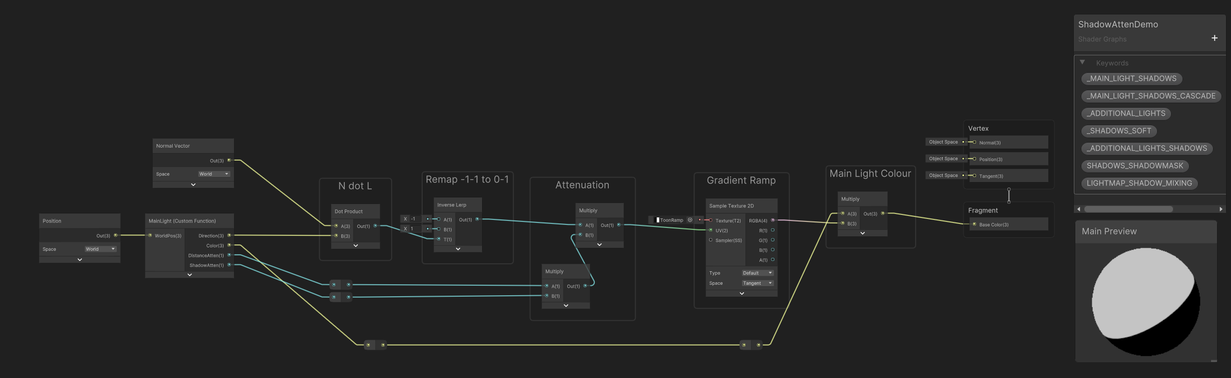
It's due to how shadow mapping works. Assuming you want the object to receive shadows, I don't think there's a way to fix it entirely. But as the OP kinda mentions you can hide it using the diffuse lighting. e.g. Toon shaders typically use something like step(0, nDotL) * shadowAtten
Eh, i just doesn't like something like that, but ok, will trying my best. Thanks!
In your toon shader examples, I see that you control the bends of the material, but is this possible for a specific light source? And, for example, add a color gradient?
Hello, where should i connect the normal and height node in shader graph? There's no normal slot in the Fragment panel
If you want to control a light other than the main directional you do that in a Custom Function as you need to loop over the lights. See the AdditionalLights_float or AdditionalLightsToon_float functions here : https://github.com/Cyanilux/URP_ShaderGraphCustomLighting/blob/main/CustomLighting.hlsl
And yes, should be possible to do a colour gradient based on the light attenuation.
If you need to have that only affect specific light(s), would likely need to branch based on the light colour or use layers. Kinda similar to what I do in this ultraviolet lights tutorial
Only Lit graph have normal ports. If you're using a lit graph but there isn't one, you might have removed it. But you can re-add by right-clicking at the end or between other blocks.

Hey all.
Anyone here writing HLSL Scripts ?
If you have a question it's better to just ask it
Cool, So my shader is turning out Black
But it only turns Black if I use the UniversalFragmentBlinnPhong() Function in the Fragment Stage.

Heres the Basic Structure I have.
float4 Fragment(interpolators input) : SV_TARGET
{
    float2 uv = input.uv;
    float4 ColourSample = SAMPLE_TEXTURE2D(_ColourMap, sampler_ColourMap, uv);

    InputData lightingInput = (InputData)0; // PositionWS : The mesh on the Current Fragment
    SurfaceData surfaceInput = (SurfaceData)0; // Albedo : The Surface material Properties

    surfaceInput.albedo = ColourSample.rgb * _ColourTint.rgb;
    surfaceInput.alpha = ColourSample.a * _ColourTint.a;

    return UniversalFragmentBlinnPhong(lightingInput, surfaceInput);
}
If I just return the ColourSample and _ColourTint Mult I get this:
return ColourSample * _ColourTint;

There's likely things in the InputData struct that you need to be setting
Perhaps... Let me go see what I am missing.
I do have these, but let me do some more Digging
lightingInput.positionWS = input.positionWS;
lightingInput.normalWS = normalize(input.normalWS);
lightingInput.viewDirectionWS = GetWorldSpaceNormalizeViewDir(input.positionWS);
Might be a little outdated in places as this was written for 2020.3, but this might help : https://github.com/Cyanilux/URP_ShaderCodeTemplates/blob/main/URP_SimpleLitTemplate.shader
Or can look at URP shaders, such as https://github.com/Unity-Technologies/Graphics/blob/master/Packages/com.unity.render-pipelines.universal/Shaders/SimpleLit.shader and it's related include files
Might also be related to SurfaceData. I would try surfaceInput.occlusion = 1.0;
Thank you, I will take a look at the Sample Shader now 😄
Ahh yes... Might be 🤔
Perhaps I also need to tell it that its an Opeque object in the tags for rendering. I just have it as UniversalRenderer
I'm having trouble getting an unlit shader in URP shadergraph to show up on a material. The main preview window works fine, but assigning it onto a material makes the entire material disappear. Changing the material to Lit makes it appear just fine, but I need to use unlit. I've tried multiple different settings and reduced the shader to just a base color, and it still won't show. Any ideas what I might be missing? Using Unity 2022.3.18

Hmm I think this may be due to a post-processing issue from one of my team members, disregard for now
General shader question. If I'm rendering a large grid of vertices, then it's easy to generate the X, Z coordinates in the vertex shader and store only the Y in the mesh data. Is this usually better than storing the full XYZ position in mesh data (along with all the other attributes of course)? Trade off is a few additional cycles in the shader vs reduced data size. I feel like I read that this usually better because a lot of shaders tend to be data bandwidth bound.
I'd look at cache coherence also....the order in which you store and access the dataset, regardless of size. But I'd hazard a guess that the smaller dataset will "win out" particularly if you can generate XZ values. There's procedural calls for drawing meshes that you might want to explore, like https://docs.unity3d.com/ScriptReference/Graphics.RenderPrimitives.html and cousins. However, you may find that you want to access memory in size of float2 or float4 chunks anyway. If float4, you'd pass the data even if generated. An interesting question, please benchmark and let us know. Mobile platforms may perform differently than desktop too.

Thanks, yeah, that link is roughly how I'd be doing this. I've also got other data alongside the position, like normals, tangents, bitangents, and some other properties required for shading. I regenerate normals in compute shader and am also considering whether the grid heights should be their own buffer entirely to help with that process. The compute shader to generate normals can write in the main buffer with the other attributes I guess... I don't really know when to split the data to make one compute shader faster vs. that it might make shading slower later given positions are in a separate array to the other attributes... cache issues doing that? It's like I want all the attributes together for shading, but for earlier compute shaders I just want specific values only... don't really have the experience yet to know when to split or keep together.
Hey! I currently am creating a lighting system in 2D URP where I am using a two pass blur to create a Starbound-esk lighting system which overlaps the blurred masked light texture with a Tilemap (of blocks/tiles) to create a similar lighting system to what Starbound uses, however there is seemingly a problem with my two pass blur shader, if I for example have a single "tile" of masked light assuming an intensity of 1 (fully bright), and run it through my vertical-horizontal blur it will simply create a larger square, which logically you'd expect it to do, I am wondering if anyone knows how to create a two pass blur that would result in more "circular" blurring pattern similar to how photoshop's gaussian blur behaves, labelled photo examples below, sorry for the potentially poor explanation!
Circular Blur Shader Question
^ Full question moved to Thread to prevent chat spam! Any help would be amazing, appreciate all of you as always! 
I trying to build a game i gat in this stuck shader and wont pass it can some on tell me how to fix this or somehow go around it

||Shader compiler: Compile Particles/Standard Surface - FORWARD, Vertex Program: Internal error communicating with the shader compiler process. Please report a bug including this shader and the editor log. Error code 0x80000004 (Not connected). Thread: 2208 Exception: Protocol error - failed to read magic number (data transferred 0/4) Platform: d3d11 Keywords: UNITY_ENABLE_REFLECTION_BUFFERS UNITY_USE_DITHER_MASK_FOR_ALPHABLENDED_SHADOWS UNITY_PBS_USE_BRDF1 UNITY_SPECCUBE_BOX_PROJECTION UNITY_SPECCUBE_BLENDING UNITY_ENABLE_DETAIL_NORMALMAP SHADER_API_DESKTOP UNITY_LIGHT_PROBE_PROXY_VOLUME UNITY_LIGHTMAP_FULL_HDR UNITY_PASS_FORWARDBASE Shader compiler: UnityShaderCompiler.exe compiler executable disappeared on thread 2208, restarting Launched and connected shader compiler UnityShaderCompiler.exe after 0.13 seconds Shader Compiler IPC Exception: Terminating shader compiler process Last 50 lines from the compiler log: Base path: 'E:/Unity Project/2022.3.29f1/Editor/Data', plugins path 'E:/Unity Project/2022.3.29f1/Editor/Data/PlaybackEngines' Cmd: initializeCompiler Cmd: compileSnippet Shader compiler: Compile Particles/Standard Surface - FORWARD, Vertex Program: Internal error communicating with the shader compiler process. Please report a bug including this shader and the editor log. Error code 0x80000004 (Not connected). Thread: 2208 Exception: Protocol error - failed to read magic number (data transferred 0/4) Platform: d3d11 Keywords: UNITY_ENABLE_REFLECTION_BUFFERS UNITY_USE_DITHER_MASK_FOR_ALPHABLENDED_SHADOWS UNITY_PBS_USE_BRDF1 UNITY_SPECCUBE_BOX_PROJECTION UNITY_SPECCUBE_BLENDING UNITY_ENABLE_DETAIL_NORMALMAP SHADER_API_DESKTOP UNITY_LIGHT_PROBE_PROXY_VOLUME UNITY_LIGHTMAP_FULL_HDR UNITY_PASS_FORWARDBASE IPCStream (hubIPCService): IPC stream failed to read (Not connected) IPCStream (Upm-12860): IPC stream failed to read (Not connected)||
!code

Posting code
📃 Large Code Blocks
Use links to services like:
https://gdl.space/, https://paste.ofcode.org/, https://hatebin.com/, https://paste.myst.rs/, https://hastebin.com/
📃 Inline Code
Surround code with three backquotes. Not quotation marks.
To format as C#, add cs to the first line:
```cs
// Your code here
```
Add a comment with a line number if there is an error message.
I upgraded from 2021.3.22f1 to 2022.3.29f1
Sure you can. If you create a separate render pass, you can write whatever you want into a separate render target and sample this screenspace texture in your object shader.
oh? where do I read the documentation on how to do this
actually that might not be it i forgot how to check where which pipeline I'm using
ok yeah never mind its LWRP which is an URP asset
but thanks imma look into doing custom render passes!
trying to do a distortion effect in HDRP but can't get scene color to give any information from transparent 2D sprites - I've heard this is a known issue but I also heard there should be some way to get a final/semi-final render texture pass without rerendering everything using a second camera to substitute the node, anyone got any ideas?
is it possible to read/write a shader file/compute file as if it was a text file from unity C#?
Not at runtime, the shader source is not included in builds. In the editor, you can just read and write to it as a plaintext file if you know the file path.
no thats fine, I just need it in editor
sweet thanks!
can I modify a .cginc file, and then recompile it and all the other files that use it like this?
As soon as Unity detects a change in the cginc file, everything using it will get recompiled, just like if you edit it yourself. But you may need to tell Unity to check by using AssetDatabase.ImportAsset.
ah sweet thanks!
also I notice a rare bug where if I am recompiling both C# and shader files at once, sometimes the shader files dont recompile and stay as the old?
Im using a render cam to render particles and then i display them on the water using a shader and it works in the editor but in the build the white foam(the particles in question) flash a lot and look extremly weird. Left image is in build, right image is in the editor


herere are the settings for my render cam

would anyone be able to help me in adding a shader to a 2D tilemap?
For sure, what do you currently have?
to be honest, i have no clue where to start with this, i have the shader i want to add, which is this glitch filter i got, but i want to apply it to the tile map and not the other objects
Okay so shaders can't directly be applied to objects, you will first need to convert your shader to a material. To do this, right click the shader you have in the project files, and hover over Create > Material, this will automatically apply the right clicked shader to a new material which you can directly add to the tilemap.
Tilemaps use a "Tilemap Renderer" component natively which you can directly drag the material you just created to, this should apply the shader correctly!
all the objects are inviable now
when creating the material did you right-click the shader during the material creation to apply the shader?
wait, hold on'
i think it not showing up is my camera
i will fix my camera and then check
Sure!
the tiles no longer appear but still have their collsion, would it be easier to make the shader affect the ground layer that the tile map is on, as only the tilemap uses that layer
The easiest solution is using a material to apply the shader to the tilemap, however if your current shader wasn't designed with tilemaps in mind they could be finnickly as I've recently been finding out, is it a shader graph?
no, it is just a shader
Yeah, if you aren't very familliar with using Shaders directly there are a multitude of things that could be going wrong, unfortunately I'm not the greatest with them myself yet. But if you send it here I could have a look.
i found this on github, i have some alternatives if this won't work
could you send the github?

GitHub
Contribute to yumayanagisawa/Unity-Glitch-Filter development by creating an account on GitHub.
Yeah since that is an older shader with very little documentation on how it actually works, if you are a beginner I'd invest in the time watching a shader graph guide which breaks down step-by-step what is going on. Jumping straight into complex HLSL shaders will only set you up for a bad time ahah.
oh, ok

Unity 2022.2 introduced a new Full-Screen Shader Graph feature, and in this video, you will learn how to add some terror to your horror game by creating a Full-Screen Glitch Effect with Unity's Shader Graph.
Download Project Files (Patrons Only): https://www.patreon.com/BinaryLunar
The Ultimate 2D & 3D Shader Graph VFX Unity Course:
https://www...
This may be what you're looking for, which will break down what is going on within' the shader graph, and what the nodes are doing.
i am going to try this tutorial out and see if i can get it to work, Thank You for the help =)
Of course! Feel free to ask any other questions you have here, and if I'm still available I'll try to help you out.
For really generic and basic questions I recommend Google's Gemini AI, it does a pretty good job linking resources that it is pulling information from which is really helpful!
random question: would it cause any problems if I were to be using unity 2D instead of Unity 3D
It can, if you are using Unity2D there are a lot of shaders which are made specifically for 2D, 2D lacks the z axis entirely and a lot of the vertex points that a shader made for 3d could be looking for. I'd stick to just 2D specific guides for now, however converting a 3D shader to a 2D shader is a whole lot easier than vise-versa, but it would be quite complicated if you are just starting to learn shaders.
From my experience it is a lot easier to find shader guides for 2D than 3D because it's simply easier to work in 2D overall.
ok, thank you!
Was that ai generated? Please avoid giving unconfirmed replies generated by ai.
that was not at all ai generated.
There is no unity 2d. Unity is a 3d engine. 2d is the same as 3d just in 2 dimensions. There are some tools and packages in unity helping with developing 2d games, but that's about it. 2d shaders wouldn't be too different compared to 3d ones.
Yes, but the assumption would be all of his assets are in 2D.
Then what the heck is "Unity2d"?
He is a beginner and most likely means the default "2D" package when creating a new project. With this assumption in mind, we can make the connection that more than likely all of his assets are two dimensional therefore making 3D designed shaders unusable or broken in their native state.
the 2D package was what i was talking about
Additionally, if that were an AI generated response. Very likely the "AI" would not reference his prior texts in the response referring to Unity as Unity 2d.
AI would be much more literal in the response.
2d package is just a collection of packages to help with developing 2d games. It doesn't change the engine.
3d shaders would work with 2d objects as expected. Unity uses the same render pipelines and shading language both for 2d and 3d.
The only issue might be with rendering order and lack of support for 2d specific features, like ordering layers(sprite renderers or 2d lights).
Ok, my bad then. But imho it's very important to let beginners know that there's no clear difference between 2d and 3d in unity.
Yeah, my response was more to push him in the right direction as far as researching goes, looking up "Unity" as a broad term will often bring a lot of guides relating directly to 3D projects, which can be very confusing when you're working in a "2D" project. Unity recently has made a pretty big push in terms of 2d-specific features that are very nice to have when making a lot of shaders a lot simpler than they'd be in 3D projects I've noticed.
But yes, natively you could hypothetically throw a 3d object into the scene with no problems haha.
I'm currently working on a 2D game and was mostly trying to get him in the right direction research-wise, but I appreciate your follow up! I am also pretty new to Unity's 2d workflow, so I also may make mistakes as far as accuracy in my responses haha. But that's just how I view it anyway.
apparently URP doesn't support multi pass shaders :(
I've finally almost figured out a way to make silhouettes work in unity 2d without spritemasks (cause this won't work for my project), and I find out that I can't even have multiple passes with conditional logic
Pass1:
Stencil
{
Ref 1
Comp Equal
}
ZTest Greater
Pass2:
Stencil
{
Ref 2
Comp LEqual
}
ZTest Always
is there a way to combine this logic so that in either case it continues, but breaks if both aren't true?
basically if stencil buffer == 1 and ZTest Greater || stencil buffer >= 2
You'd use render features in SRPs for that
oh god do I really gotta learn all that
it's lowkey a jank solution lol
What exactly are you trying to do?
ok well it's kinda complicated but I have a "2.5D" project where I want a silhouette to display when a player is behind occluding objects. I have it working fine for this; however if an occluding object is behind and in front of the player it displays the behind occluding object over the silhouette. This is because the occluding/occluded objects are sorted in relation to the camera by the y axis. Ex: the lower the y axis is, the closer it is to the camera
the occluding/occluder objects also use a material separate from the rest of the project
I'll send screenshots in a sec


in these screenshots its working perfectly
wait a second it's working perfectly right now I'm confused
I have no idea why it's working now
there's no way; I'm so confused. I just spent nearly 2 days trying to fix this and I changed one number by accident and it suddenly works?!?!
Anyone who can help me out with something? I a shader with URP settings. I need to cut out a hole. It seems to work, but for some reason it's also shown from angles it's not supposed to. For example in the last photo from below.
Shader "Custom/StencilMask"
{
Properties
{
[IntRange] _StencilID ("Stencil ID", Range(0, 255)) = 0
}
SubShader
{
    Tags { "RenderType"="Opaque" "Queue"="Geometry-1" "RenderPipeline" = "UniversalPipeline"}

    Pass
    {
        Blend Zero One
        ZWrite Off

        Stencil
        {
            Ref [_StencilID]
            Comp Always
            Pass Replace
        }
    }
}
}


_ObjPos ("ObjectPosition", float) = (0,0,0)
how could I set this variable from script?
or have I set it up wrong
I just need to store three floats
or two, two works as well
If you want a vector, the syntax is
_ExampleName ("Example vector", Vector) = (.25, .5, .5, 1)
https://docs.unity3d.com/Manual/SL-Properties.html
Then inside the CG/HLSL portion, float4 _ExampleName;
From C# you'd set using material.SetVector("_ExampleName", someVector);
great! that worked
how could I get any given pixel's distance from that position?
Transform the vertex position to the same space (e.g. world, using model matrix), pass to fragment and use distance(positionWS, _ExampleName.xyz);
any reason why am i not getting shadows when the rendering mode is fade for the plane?

i am getting shadows in opaque mode, but the greys cannot look like this, it has to be transparent

hmm passing that value in to the A just makes it all transparent
yeah im passing it in for a but it just seems to be returning 0 no matter where it is
ohh I see what I did
col = float4(0,0,0, ((distance(i.worldPos, _ObjPos.xyz))/_Power));
ok so this is changing the distance of the vignette
how can I change the falloff
does mipmapping work on alpha channel? I am trying to use texture2d LOD to get a blurred alpha map but no matter the lod setting the alpha remains unblurred
(this is on a rendertexture)
Should do afaik. Is the render texture set up to automatically generate the mipmaps?
Thanks. Yes it is. It works on the RGB but not on the A it seems
wait, no, thanks for making me double check it, no it;s not. these settings :

Hey!
This is my current Cel shader and i was wondering how i could add to it that it casts and recives shadows?
Thanks for any help!

Would need custom functions. If you're using URP I've got some subgraphs here - https://github.com/Cyanilux/URP_ShaderGraphCustomLighting

GitHub
Some custom lighting functions/sub-graphs for Shader Graph, Universal Render Pipeline - Cyanilux/URP_ShaderGraphCustomLighting
Ty, what subgraphs would i need for the shadow to work?
Main Light Shadows
kk ty
Using smoothstep(min, max, dist); might be a good way to remap the distance into a 0-1 range
I don't use the Built-in pipeline much, but iirc it just doesn't do shadows for transparents. Not sure if there's a way around it 🤔
Hello there ! I'm looking to change smoothly the speed of a panner. Is there a trick that allows to not have this rough transition ? (It's happening when i'm manually moving the speed parameter and i'm not quite sure it would be resolved even if it was a script that changes it) :/

Rather than doing time * speed in the shader, you want a C# script to calculate the offset (e.g. offset += speed * Time.deltaTime in Update) and pass to the shader
Yup, that's the only thing that came to my mind too, I hoped there was another solution in the shader ahah, thanks :d
OK, so this is a little bit of an ongoing issue from my adventures in #🤯┃augmented-reality channel, but it's more appropriate to continue here
I used a bunch of SystemInfo debugs and figured out that the GPU on the phone I'm using for this project does support compute shaders with OpenGL ES 3.2, but in a specific way - only compute and fragment shaders can have compute buffers (up to 24), while domain/geometry/hull/vertex shaders cannot have any.
The way I think I'm going to approach this is to write a compute shader that takes in the position and color data as a struct of two arrays in a single buffer, then performs transformation and writes the position to two textures. Then, in the vertex shader, I'll sample the textures and draw the points. I guess at this point I could also just instance some mesh or quads at those points as well.
I just have to figure out how to properly call this from the C# script to ensure that it all flows correctly
Hi everyone!
I'm trying to make a cutout shader that will work to procedurally place windows in a wall.
Here's where I'm at.
I have a cutout shader writing to the stencil buffer
I have an opaque shader that renders when the stencil buffer is not equal to what the cutout writes to it.
Here's my problem.
Cutouts behind the mesh still cut out the mesh.
The cutout cuts all meshes behind the shader, I only want to cut one wall per cutout.
Here's what I've tried.
Writing the depth data to the buffer to use this as a comparison, however I'm not sure how to use the 2 in conjunction.
Any ideas?
can I make a shader bigger than the sprite it is on? (i;e a simple 2d shadow)
I'm using a Matrix4x4 property to transform some positions, directions, and normals.
I have discovered that to correctly transform a vector that represents a surface normal, you have to multiply it by the inverse of the transform matrix you intended to use (so, for object-to-world, you use the world-to-object matrix truncated to 3x3). I read about it here while digging around for info: http://digitalrune.github.io/DigitalRune-Documentation/html/8c5feee3-4973-8c84-e032-bdb901ea0fb2.htm
And it works!
But I don't understand why -- isn't a world-space normal vector conceptually the same thing as a world-space direction vector?
clearly it is not!
you could deform the sprite's mesh in the vertex stage, I guess
but then you'd have a distorted sprite!
It also says this:
(Note: If the transformation matrix contains only rotations, translations and uniform scalings then TransformDirection(Vector3F) can be used to transform normal vectors, which is faster.)
Do you have non-uniform scaling?
that's confusing too, since that implies that both TransformDirection and TransformNormal will have identical outcomes, even though one uses the matrix and one uses the inverse of the matrix
unity c'est bien ce serveur là
iirc when doing the normal transform you have the matrix in the second param of the matrix multiply. That acts like transposing the matrix (flipping along it's diagonal, swapping rows/columns)
Oh! That's the ticket.
I noticed I was randomly seeing the matrix on the "wrong side", but I figured I was uh
I don't know, having a skill issue w.r.t. linear algebra
Do the default values not work for a Matrix4x4 property?
It looks like I'm getting an all-zero matrix even though the default is set to be the identity matrix
(in the shader graph)
this is causing some very wild artifacting!
i added a check for an all-zero matrix that just skips using it, but I'd rather not have to do that..
Maybe a zero matrix got serialized for some reason, overriding the default.
Can someone help me understand why this produces results based on the world orientation of the camera? If I look along positive Z axis, I get negative numbers, and when I look on negative Z axis, I get positive numbers.
The documentation for "Camera" says that direction is the camera's forward Z axis. It doesn't specify a space, but I'm assuming world? And for "View Direction" it says that it's the position from the fragment/vertex to the camera. Yet, it doesn't seem to be doing that?

I'd expect this to be 1 if I am perfectly looking in the opposite direction that the fragment's "view direction" is facing, and -1 if I am looking the same direction the fragment's "view direction" is facing.
When coding a shader, what's the best way to make the object render on top of everything else?
ZTest Always
Maybe you also need to make it render last using renderqueue = 9999
Doesn't render queue stop at 5k?
I don't think one minus is a correct node there.
Try calculating on paper (1,1,1) - (0,0,1). That wouldn't result in an opposite direction.
Oh, right, I forgot about that.
oops
This might not be a shader question, but im trying to make a flat shaded grass object that recieves lighting. The problem i have right now is that when i look towards the light source, the surface of the grass model I'm seeing right now is dark.
I need the whole thing to be like the lit side of the face. also, when the face is lit from the side both sides gets dark, which also doesn't look very good.
I tried to edit the normal directions in blender to point straight up, but i can't seem to get that working
Try subsurface scattering if that's available
I'm in URP it doesn't look like it
I was thinking I could have a script on each foilage object that casts towards the lights and calculates a color from that (i have like 200 foilage in the scene at a time)
I'm not sure with urp, but in built in, you can just use diffusewraping, basically its just remapping the light value from 0~1 to 0.5~1
There appears to be no serialized value at all.
I inspected the material in a text editor
Matrix4x4 doesn't show up in the inspector
Oh, yeah, material only supports these property types, my bad.
https://docs.unity3d.com/ScriptReference/MaterialProperty.PropType.html
afaict it just does not use the default value at all
Good morning. I'm still pretty new to ShaderGraph. But, these two nodes. Based on what you see in my picture, isn't this 1/1, and shouldn't the color still be white in the right node?

the length could be greater than 1
This seems to explain the problem:
https://forum.unity.com/threads/non-exposed-parameters-dont-work.912149/
Though, they suggest that matrices should default to identity, I don't see how that would work unless HLSL has that behavior built-in. It makes more sense for any uninitialized uniforms to default to zero.
Is there a way to stop shadergraph automatically creating a material? I always end up creating a new one elsewhere, so I presume I have two materials and can't delete the automated one?

The default value for unexposed properties is only for the shader preview in the graph editor. They renamed it in 2023.3 to better communicate this.
I see.
weirdly, this isn't completely preventing the bad behavior -- I still wind up with a mesh that flickers in the viewport until I enter play mode (at which point my script starts setting the transform matrices)
Maybe it's reading some uninitialized memory with garbage non-zero values.
Are there any tools available for building HLSL with HDRP? Visual studio doesn't really pick up the code. I see there are people who are building HLSL shaders for HDRP but have no idea how they manage to build for it. Would appreciate any insight.
Feels like it, yeah...

No, this has been added with material variant.
The point is, you can use this material that mimics the shadergraph default values as variant source for other materials and inherits the settings. So when you change the shadergraph later on, all the changes will be reflected to all child variants.
Good example : it is the only way to sample a texture in the vertex stage.
I.E. : displacement
Are you trying to set matrices globally?
No, the matrices are being set on the material via script
This page explains why it's necessary
Oh right I see. I guess the matrix isn't initalised until entering play mode. May need to use [ExecuteInEditMode] on the script
The regular Sample Texture 2D node wants to look at gradients based on neighboring pixels
and well...there are no pixels in the vertex stgae!
I could do that, but I'd prefer for the shader to just work properly without a script feeding it values!
it should just default to an identity matrix
that does not look like the zeroth row of an identity matrix 😉


it's some catastrophically large value that's blowing out the camera
Can't you inspect the matrix node to check the values ?
I've had some similar issues before, I think it might be a bug related to SRP batching
As if you break srp-batching compatibility on the shader, it does actually use an identity matrix then
do you mean the Node Settings for the property?

hmm, i can try doing that
Yes, I was thinking of this one.
If you didn't already overwrite the value by a script or somethings, taths what should be used in the shader 🤔
it's a bit weird because it's not an "exposed" property
or at least I can't toggle that box!
other than assigning a material property block, is there something i can do without adding code?
Yeah, matrices can't be exposed 😦
Matrices are weird because they can't be "exposed" to the material as they don't get serialised - but by default the srp-batcher still treats them as objects set per-material, unless you use the override property declaration
Split the matrix in 4 vector4 😅
to break srp batching, I mean
ah, you can turn it off by putting the inspector in debug mode on an HDRP asset
yep, that does it
so i'm probably getting some weird uninitialized memory
So the SRP Batcher isn't clearing its uniform buffers 🤔
Worth it for the performance, maybe.
the frame debugger shows sane values here during the GBuffer step

although, interestingtly, I don't see the matching _Ellipsoid_To_World matrix
Is it used in the shader?
oh
i deleted it lol

(because it was causing wild artifacting)
let's put it back
I was only using it in the fragment stage
well that's a little bit funny

but the matrices are showing up as normal identity matrices
they're also fine during the batch that draws the cube in DeferredDepthPrepass
the problem is that the mesh just...leaves entirely when I actually apply the transform matrices
it goes to space
or randomly makes a chunk of the screen turn white
i'll use them for something pointless
Maybe it doesn't show up properly in the frame debugger?