#archived-shaders
1 messages · Page 77 of 1
and remove .rgb
it's a error from my part
Final version is : col += tmp.a * TextureMainTexture.Sample(Sampler, UV + offset).a * tmp;
okay
so I have:
void GaussianBlur_float(UnityTexture2D TextureMainTexture, UnityTexture2D TextureLight, float4 Texture, float2 UV, float Blur, UnitySamplerState Sampler, out float3 Out_RGB, out float Out_Alpha)
{
    float4 col = float4(0.0, 0.0, 0.0, 0.0);
    float kernelSum = 0.0;

    int upper = ((Blur - 1) / 2);
    int lower = -upper;

    for (int x = lower; x <= upper; ++x)
    {
        for (int y = lower; y <= upper; ++y)
        {
            kernelSum ++;

            float2 offset = float2(_MainTex_TexelSize.x * x, _MainTex_TexelSize.y * y);

            float4 tmp = TextureLight.Sample(Sampler, UV + offset);
            col += tmp.a * TextureMainTexture.Sample(Sampler, UV + offset).a * tmp;
            //col += Texture.Sample(Sampler, UV + offset);
        }
    }

    col /= kernelSum;
    Out_RGB = float3(col.r, col.g, col.b);
    Out_Alpha = col.a;
}
seem right.
could you point out where the cutoff is referenced, or where I could multiply the alphas to apply it again I guess?
TextureMainTexture would be you cutoff texture
I'm just a little confused since I've never used a custom hlsl shader before
oh but that is a UnityTexture2D
oh
wait you mean we are doing everything in this custom script
so I shouldn't even bother cutting beforehand
yep
ahhh, okay I was very confused sorry
this is your cutoff texture, right?

yes
I connect that directly into the gaussian blur script
along with the light texture respectively
so _Maintex... to TextureMainTexture and etc
yes yes, okay I will test it. Thank you very much!
Let hope for some result
I might be a bit to fiddle with it to understand it further but I will let you know if it works!
Haha let's hope!
Hey! I'd like to use Unity to do some offline video processing. More specifically, I want to get a video file, apply a simple shader to each frame, and save the video back to a file. Anyone have any suggestions on how to achieve this? (On a side note, I'm sure there are other, perhaps more suitable, approaches to this. However, Unity's something I know how to use, and due to the project's details, I don't really have the time to learn something new. Despite that, do suggest other tools if you think they're worth it.) Thanks in advance for any help!
Soo a bit of a weird result, the outside black area is the "Cutout Texture", and the light is the light texture, however now when I test it after connecting all the nodes it not only doesn't seem to be blurring as-well as, on the later part of my shader graph where it is supposed to mask the overlapping light to reveal the "cutout texture's" texture, has a really weird blocking as shown in the image below:


hey folks, is there a good resource where I can learn to use SRP deferred rendering path in depth? I feel like only the forward path is encouraged
okay, update it is blurring on the edges shown here:

Also, I feel like I am cluttering this channel so I'll create a thread, sorry guys.
Im trying to make a really simple sky shader with a half sphere that follows the player
However for some reason I see the grid that the vertices have


And this is the shader
Shader "SkyShader"
{
    Properties
    {
        _Color ("Color", Color) = (1,1,1,1)
        _MainTex ("Albedo (RGB)", 2D) = "white" {}
        _CellSize ("Cell Size",Float) = 2
        _WindSpeed ("Sky Speed", Float) = 1
        _Strength("Sky Strenght", Float) = 1

        _Transparency("Transparency", Float) = 1
        _Offset("Offset", Float) = 0

        [Toggle(_SMOOTH_OUT)] _SMOOTH_OUT ("_SMOOTH_OUT", Float) = 0.0
    }
    SubShader
    {
        Tags {"Queue" = "Transparent" "RenderType"="Transparent"}
        LOD 200
        CGPROGRAM
        // Physically based Standard lighting model, and enable shadows on all light types
        #pragma surface surf Standard addshadow alpha nofog
        #include "Assets\sapra.InfiniteLands\Resources\Helpers\Voronoi.cginc"
        #include "Assets\sapra.InfiniteLands\Resources\Helpers\Simplex.cginc"
        #pragma shader_feature _SMOOTH_OUT

        // Use shader model 3.0 target, to get nicer looking lighting
        #pragma target 4.0

        sampler2D _MainTex;

        struct Input {
            float3 worldPos;
        };

        float _CellSize;
        fixed4 _Color;
        float _WindSpeed;
        float _Strength;
        float _Transparency;
        float _Offset;

        void surf (Input i, inout SurfaceOutputStandard o) {
            float3 value = (i.worldPos +_WindSpeed*_Time )/ _CellSize;
            float noiseA = (snoise(value)+1)/2;
            float noiseB = (snoise(value*2)+1)/2;
            float noiseC = (snoise(value*4)+1)/2;
            float noiseD = (snoise(value/2)+1)/2;

            float result = (noiseA+noiseB+noiseC)*noiseD;
            result = saturate(pow(result, _Strength)-_Offset);

            #if _SMOOTH_OUT
            result *= smoothstep(0,1000,i.worldPos.y);
            #endif

            o.Albedo = result*_Color;
            o.Alpha = saturate(result*_Transparency);
        }
        ENDCG
    }
}
Do i need to disable or enalbe something to make that disappera?
It onlt appears on the semi transparent parts
what is fresnel? is it just the area your see around or is it a reflection?
Fresnel is meant to model how things are more reflective at shallow angles; in shader graph it's just a function that goes from 0 when view direction dot normal is 1, to 1 when the dot product is zero, with some power-law behaviour in between.
https://docs.unity3d.com/Packages/com.unity.shadergraph@6.9/manual/Fresnel-Effect-Node.html this has the code for it
Hey, so I am currently trying to make a Custom Function Shader Node in Unity's shader graph system, and this particular script is (supposed to) delete all of the overlapping "TextureLight" that overlaps with "TextureMainTexture" then blur it using the for loop below, however this isn't working as intended, I am fairly sure the cutout portion isn't working at all. I have reasons to believe the blur is in fact working though. ```csharp
void GaussianBlur_float(UnityTexture2D TextureMainTexture, UnityTexture2D TextureLight, float2 LightUV, float2 MainTexUV, float Blur, UnitySamplerState Sampler, out float4 Out_RGBA)
{
float4 col = float4(0.0, 0.0, 0.0, 0.0);
float kernelSum = 0.0;
int upper = ((Blur - 1) / 2);
int lower = -upper;

// cut out light from Texture

for (int x = lower; x <= upper; ++x)
{
    for (int y = lower; y <= upper; ++y)
    {
        kernelSum++;

        float2 offset = float2(_MainTex_TexelSize.x * x, _MainTex_TexelSize.x * y);

        float4 tmp = TextureLight.Sample(Sampler, LightUV + offset);
        col += tmp.a * (1 - TextureMainTexture.Sample(Sampler, MainTexUV).a) * tmp;
    }
}

col /= kernelSum;
Out_RGBA = float4(col.r, col.g, col.b, col.a);
//Out_Alpha = col.a;
}```

Why do some parts of my model ( blades in my grass model ) appear brighter than the other ones? They have same UVs and same texture, same lighting conditions whats the issue here
It's an issue I see quite a bit with backfacing normals! if the grass is small enough ill sometimes cheat this by just setting the normals to point in the direction of the surface they're on top of
Like hol said, it's the normals. The blades of grass that are facing the light are brighter than the ones that are more side on.
I had a question for shaders when working on URP for Android. I have a water shader I got from the Unity asset store from a pack called Toon Fantasy Nature. I attached the shader material to a plane and built terrain around it. In the scene view, it looks exactly how I want it to but in the game view, it's a completely flat solid color. Is this becuase I need to enable post processing on the main camera? This is going to be for a Oculus app and I've heard post-processing is a performance killer for VR so I really don't want to have to enable it


I think the problem you're running into is actually depth texture related which is potentially a performance issue as well. You should test to get an idea of the impact but if you go into your urp asset you should be able to turn on the depth texture there.
https://m.youtube.com/watch?v=oh12OXjxALo
Here's a vid I found explaining how to turn it on.

Thanks, I'll take a look at it
is there any good tutorial on grass culling and lod with compute shader on unity 2023
rn it's kinda 💩

void Update()
{
    if (lastDensity != density) // For changing density in runtime
    {
        lastDensity = density;
        UpdateDensity(density);
    }
    Graphics.RenderMeshInstanced(rp, mesh, 0, instData); // mesh - 4 planes crossed, instData - Matrix4x4 with grass positions
}```60k meshes on 300x300 are giving me smth like 60fps, and nothing is culled, also lod is not applied to distant grass
i already have a lod mesh which is just 2 planes crossed instead of 4
Anyone got any idea on how I could achieve this 'top face block edge lit up/different color effect'?
I am already trying to pass in extra data to shader graph (vector for each vertex, if it's zero then no effect) with poor results

atm I got something like this

passed in vectors look are like this

I also tried using the step node, but because of vertex blending or something the full test color area is larger on the corners and it is not the same width (blue lines show the width of test color area)

Hey! Just wondering if anyone who's familiar with HLSL knows possibly why the following code after 2 "blurring" the light color turns yellow, the script also doesn't appear to be blurring anything at all, it's a bit of a tricky situation as I am needing to blur a "float4" / RGBA value as the input. Any help would be beyond appreciated! I've spent roughly the past 25 hours trying to get this working and I believe I am quite close, thank you all in advance!
void GaussianBlur_float(float4 lightRGB, float Blur, out float4 Out_RGBA)
{
    float4 col = float4(0.0, 0.0, 0.0, 0.0);
    float kernelSum = 0.0;

    int upper = ((int)(Blur - 1) / 2);
    int lower = -upper;

    for (int x = lower; x <= upper; ++x)
    {
        for (int y = lower; y <= upper; ++y)
        {
            kernelSum++;

            float2 offset = float2(_MainTex_TexelSize.x * x, _MainTex_TexelSize.y * y);

            float4 tmp = lightRGB + float4(offset, 0.0, 0.0);  // Assuming lightRGB contains RGBA values
            col += tmp * tmp;
        }
    }

    col /= kernelSum;
    Out_RGBA = float4(col.r, col.g, col.b, col.a);
}

My shader is supposed to overall take my 2d light texture, mask out to only fill areas where the _MainTex has an alpha of 0, then blur the masked light texture. However, currently this script just leaves me with a totally off-black color that I set in the "Lerp" node. Any help would be super appreciated!
It solved my problem with the shader graph but I'm not exactly sure how it would work with a skybox. My suggestion would be to look up that issue with what specific render pipeline you're working with. It might also be an issue with the material of that skybox not being converted to you current render pipepline
I'm trying to understand your intended behavior. The nested loops look like you are trying to access adjacent pixels, but then you just end up adding those x and y values to lightRGB's red and green channels (Which is why you are seeing Yellow by the way).
My guess is that your intent is to add the sampled color of the adjacent pixels. Is that right?
ahah, sorry I am very new to HLSL as you can probably tell and I was referencing an online resource for a gaussian blur hlsl code, which I very clearly have compromised in the process. My intended goal is to input an RGBA (float4) of my masked light texture, which will then ideally blur.
by "blur" you mean that want to do some sort of mixing of adjacent pixels, right?
Ah I see now where the red and green channels are being altered.
yes, just averaging out to create a blur effect.
and then the "blur" amount would determine the amount of passes of blurring it does in theory.
If you are aware of a less resource-consuming method I would also be open to that haha.
You're in a bit of a tricky situation here. the lightRGB value that you are passing into your custom node, contains the samples color of 1 texel of your texture. It does not contain the texture itself and there for it has no access to the color of adjacent pixels.
that does make a lot of sense!
I am not opposed to directly referencing the light texture in the custom node (which is what I was doing before) however, I really couldn't get that to work either. And I thought this would simplify it.
But I do really appreciate you letting me know of that oversight haha.
I will really quickly grab my old code that referenced both the textures and UVs and (tried) to mask out the light texture. (it wasn't masking before blurring at all)
void GaussianBlur_float(UnityTexture2D TextureMainTexture, UnityTexture2D TextureLight, float2 LightUV, float2 MainTexUV, float Blur, UnitySamplerState Sampler, out float4 Out_RGBA)
{
    float4 col = float4(0.0, 0.0, 0.0, 0.0);
    float kernelSum = 0.0;

    int upper = ((Blur - 1) / 2);
    int lower = -upper;

    // cut out light from Texture

    for (int x = lower; x <= upper; ++x)
    {
        for (int y = lower; y <= upper; ++y)
        {
            kernelSum ++;

            float2 offset = float2(_MainTex_TexelSize.x * x, _MainTex_TexelSize.x * y);

            float4 tmp = TextureLight.Sample(Sampler, LightUV + offset);
            col += tmp.a * (1 - TextureMainTexture.Sample(Sampler, MainTexUV + offset).a) * tmp;
        }
    }

    col /= kernelSum;
    Out_RGBA = float4(col.r, col.g, col.b, col.a);
    //Out_Alpha = col.a;
}
``` This code had a direct reference to both textures, and UVs (the maintex UV reference was to my knowledge useless and can be removed)!I don't use ShaderGraph much so take my advice with a grain of salt, but i think you either need to pass in the whole texture and sample it yourself, or you need to set up ShaderGraph to samle the adjacent pixels and then pass those in to your custom node (or possibly some existing Mix Node)
Yeahhh, I decently understand creating shaders using non-custom nodes. So all I am really looking to do in this older custom hlsl script, is return a light texture / RGBA of my light cut out from the maintex that is referenced and then blurred based off an exposed float I can change.
In that code it looks like the TextureMainTexture's alpha value is used to modulate the intensity somehow. I'm sorry but I don't have a solid solution for you. Now that you know why your existing code isn't behaving properly, I'm sure you'll find a solution.
Yeah, I guess I'll keep trying things haha. In theory it sounds really easy but it turns out to be a terribly tricky problem to solve.
I'm 30 hours deep now haha.
Good luck
I appreciate you letting me know about the single pixel thing
Idk how
But with just a MonoBehavior i get 60fps running 100k meshes
And with compute shader which culls far away grass and also applies lod to distant one, i get 30fps on 50k meshes...
How the heck are compute shaders supposed to work
Think it's all because of buffers which don't really clean themself each update as well as AppendBuffer just not letting me work with Matrix4x4 array to do everything fast
Are there like any grass tutorials which have more than 60fps on 100k meshes based on compute shader???
guys who knows how to make a shader graph with an ajustable alpha that will render the colour black on both sides
i did something like this but it doesnt work

I am pretty sure you can just disconnect every node and set the base color to black and attach just a simple alpha
which you could adjust
(to the alpha output)
oh okay ill try that thanks
oh i know what it was it was another issue thanks it worked
glad it worked!
I'm writing some custom shaders for VRSL (https://github.com/AcChosen/VR-Stage-Lighting) and I'm having some bizarre bugs.
To keep it brief, VRSL works by grabbing DMX channel information from the color channels of a texture in such a way that you can use something like OSC or a video livestream to control it in real time.
The custom shader I'm trying to write is meant to have 24 "LEDs" that are controlled by 50 DMX channels. The control is scheme needs to be like this:
- Channel 1: Master intensity of channels 2-37
- Channels 2-37: RGB channels of 12 RGB LEDs
- Channel 4: Master intensity of channels 39-50
- Channels 39-50: Intensity controls of 12 White LEDs
I almost have this thing fully functional, but here is the current issue:
- DMX channel 23 (the red channel of the 8th RGB LED) is lighting up the first RGB LED as if it were a White LED
- DMX Channel 48 (the intensity channel of the 10th White LED) is lighting up the 12th RGB LED as if it were also a White LED
The pic I'm sending in this message is of the custom light fixture I'm working on. The top and bottom rows are the 12 RGB LEDs and the middle row is the 12 White LEDs.

Here's my code, as well
im sorry im not sure this is the right channel but basically i want the cactus to be infront of the brownish "background" my idea is to make like a tile building game but anyway i have the background on the default sorting layer but when i change my cactus to the sorting layer cactus and building it does show up onfront but it doesnt have color, its just black and white, how is this possible?
just figured out the same thing happens with the tiles, which are just square sprites

Hey guys I am new to shader creating and I tried to make a Scope_Zoom shader and assigned it to a sphere and it shows pink for some reasons
Here is some more info
-
This scene was created as standard urp
-
The other material which were normal used the standard shader
-
this zoom shader I created using the shader graph and than created a material which used this shader
-
it showed pink when I assigned it
-
I also am doing this due to code monkeys zoom shader tutorial


When you created your shader did you create urp shader? and then did you right click on your shader to create the material? Sounds like the material is not urp
it shows Universal as a target so I assume it should be URP compatible. I'm also wondering whether it could be the Scene Color node that doesn't work. You could remove that node and only use the default grey as a color to cofirm the problem is not in the node setup itself
struct Input
{
    float2 uv_MainTex : TEXCOORD0;
};

void vert(inout appdata_full data, out Input o)
{
    UNITY_INITIALIZE_OUTPUT(Input, o);

    data.vertex.x += o.uv_MainTex.y;
}

void surf (Input IN, inout SurfaceOutputStandard o)
{
    o.Albedo = float4(IN.uv_MainTex.yyy, 1);

    o.Metallic = _Metallicness;
    o.Smoothness = _Smoothness;
}

I want to add some kind of displacement based on y value of the uv
but its not working for some reason
when i watch tutorial video why are they getting these previews an im getting this. it still works the same but just unsure


so my preview is empty not sure why

I have a shader pack, for use with 2d sprites
Is there someway I can make an outline shader for a 3d object, that would output the outline to a sprite/render texture that I then could use the shader packs, 2d sprite shader on?
Yes it was urp
Sure I will give that a try
Nope it doesn't works unfortunately
What version of shader graph was this made in?
It still shows the material as pink
I've had problem with shader graph upgrades before:
https://docs.unity3d.com/Packages/com.unity.shadergraph@16.0/manual/Upgrade-Guide-10-0-x.html
14.0.9
sounds like incompatibility issue then
What are you active targets set to in the graph?

Nevermind just seen the picture above(ignore above 😂 )
I will retry creating the project again using 3d urp and import everything there
And chnage the mats ti urp unlit
Best call, hopefully it works Justairman 👍
Inshallah
Now it is not showing pink anymore Www but instead of showing the screen color it is showing gray

Nvm it did work but now its just gray instead of the scene color
Is it meant to be transparent with an alpha of 1?
How to create more than 4 vertex color layers on URP? Do you guys know any tutorial link?
This is the best community fr fr
Hey I actually did a mistake the alpha is supposed to be 1 and it should still be invisible but now that I changed it back to 1 and tried to make it work it doesn't 😦
No, alpha = 0 means object its fully invisible, alpha = 1 means object is fully opaque
Wait I will show you mine and code monkeys shader graph and look there exactly the same


Expected

Actual

Do you have anything in your scene?
Besides you're looking at in editor, not in play mode
Have you enabled the Opaque Texture on the URP asset?
It doesn't work their either

I do not quite understand
If the tutorial you're following uses the Scene Color node I would hope it covers this
Unfortunately not
Well, you'll need to locate the pipeline asset. Likely in the Settings folder under your Assets. Might have multiple per quality setting too.
On them there's an Opaque Texture option which you need to enable for the Scene Color node to function.
Omg that works not it is also zooming
You literally made my day
Hello, is it possible to convert this code to shader graph? Thank you! 🙂
                fixed4 pixelColor = tex2D(_MainTex, i.uv);
                float opacity = pixelColor.a;
                float4 background = float4(0,0,0,0);
                float3 color_withoutAlpha = (pixelColor.rgb - ((1.0-opacity) * background.rgb)) / opacity;

                if(opacity > 0.3){
                    pixelColor = fixed4(color_withoutAlpha.x, color_withoutAlpha.y, color_withoutAlpha.z, 1);
                }
                return pixelColor;
            }
with built-in, how can i cull ONLY parts of the object that are behind the object's own geometry?
are you refering to backface culling?
Is that the "Cull Back" instruction?
ye
Hello, I am trying to create a cartoonish water surface but I am not sure how I can do that, all the tutorials I have searched on youtube are very old and some of them mention URP & HDRP shader option but I don't seem to have it, I am using unity built-in shaders.
Nah, basically I have a cube without a top or bottom, that supposed to be some sort of barrier
Using Cull Back makes it so the back of the barrier is not drawn
But using Cull Off makes it so the barrier looks weird

I wanted to see what it would look like without the doubling effect
learn shader fundamentals and you won't need a tutorial for a water shader. I can recommend freyas tutorials on youtube if you want to make shaders in hlsl.
Is it possible for you to link me to the videos?
actualy catlikecoding is probably better search it up on google it's a website
I still don't understand what you want to achieve


it's like to never have two layers of the barrier on top of one of another and not to use cull back
so maybe it's more something like depth masking
cull back gets me half of the way there
I think I get what you want
here it would look like it looks at the back, at the front aswell
just in case it still wasn't too clear
so never overlapping visually
You may need to do it in two passes. Like, render front faces with ZWrite On. Then render back faces, with regular ztesting (ZTest LEqual), so the back faces aren't drawn over the front ones. Use render queue to force the order.
(Or if you want the reverse, render back faces to stencil, then front faces with stencil NotEqual comparison. But I think that would probably look quite odd)
oh okay, this seems like a lot with my current experience with shaders but sounds like it makes a lot of sense, i'll see if i can figure it out
i'll just focus on the first option
ty
Hey, so I have a custom hlsl shader node which is meant to take two texture 2d inputs (tilemap and light texture 2d) and mask / cutout all light texture that overlaps with the tilemap. Then after masking blur the light texture, the problem is my light texture does not seem to be masking before blurring as the images will show, I've ben working at this for a very long time now and really can't seem to get anything working.
void GaussianBlur_float(UnityTexture2D TextureMainTexture, UnityTexture2D TextureLight, float2 LightUV, float2 MainTexUV, float Blur, UnitySamplerState Sampler, out float4 Out_RGBA)
{
    float4 col = float4(0.0, 0.0, 0.0, 0.0);
    float kernelSum = 0.0;

    int upper = ((int)(Blur - 1) / 2);
    int lower = -upper;

    // Iterate through the blur kernel
    for (int x = lower; x <= upper; ++x)
    {
        for (int y = lower; y <= upper; ++y)
        {
            kernelSum++;

            float2 offset = float2(_MainTex_TexelSize.x * x, _MainTex_TexelSize.y * y);

            // Sample the main texture alpha to mask the light texture
            float mainTextureAlpha = 1 - TextureMainTexture.Sample(Sampler, MainTexUV + offset).a;

            // Mask the light texture using the main texture alpha
            float4 maskedLight = TextureLight.Sample(Sampler, LightUV + offset);
            maskedLight *= mainTextureAlpha;  // Apply the mask

            // Accumulate the masked and blurred values
            col += maskedLight;
        }
    }

    col /= kernelSum; // Average the accumulated values to get the blurred result
    Out_RGBA = col;
}

my result ^

^ goal for masking

^ final goal
if anyone has any insight as to why that may be I would extremely appreciative as to maybe some insight, this has been plaguing me for a few days now and I'd really like to get to the bottom of it, thank you so much in advance!
I am not sure if this is the right place to ask this but does anyone know any good content creator who properly explains how shaders work and how to set them. I want to learn to create shaders for water and also objects using the built in shaders pipeline.
I would watch a basic shader guide on youtube, I'll DM you some I watched to help me.
That would be great, thanks.
sent!
Does it look blurrier with more samples? The problem with blurring in a shader graph is usually it's pretty hard to make things very blurry. You could try blurring using mip levels if the light texture generates them.

it does get blurry! I think my issue is the first step here ^ might be clipping the wrong part of the light texture and leaving just the overlapping light?
it's a very specific step that isn't working that I just cannot seem to figure out.

it's not the exact textures as they both can't really be exported to my knowledge, however the left is a tilemap made up of ruletiles, and the light is just a freeform light in unity which I sample with the "light texture 2d node".
Yes, but the left one is technically a group of smaller tiles so I need the light to be connected to a screen position UV for it to apply to the entire texture, otherwise it gives a separate shadow for each tile in the tilemap ahah.
my suspicion is that the masking that is taking place is taking the inverse of what this example is taking ^
so it's leaving only the light that is overlapping the tilemap
You could always invert again and check! But I have a suspicion there's a bigger assumption that's tripping u up
Yeahh, I think I would've had it solved by now if that were the case to be fair.
I'm thinking it has something to do with the tile map right now
To blur an object you need a texture that accounts for the whole screen
very likely, I had someone try to help who got everything to work. But he was using a texture2d he made out of a screenshot of my tilemap.
What is the alpha in the tilemap mask texture in the area where you want the light to stay?
it is fully opaque so it should be 1, but I could just be assuming that as I am not sure of a way to confirm that.
In the visualization, the outside looks white and opaque while the inside looks transparent.
The hole is where you want the light texture to stay unaffected?
Yes exactly
like this
Based on your code, you're multiplying the light by zero then, if the alpha in the hole is zero.
float mainTextureAlpha = 1 - TextureMainTexture.Sample(Sampler, MainTexUV + offset).a;
so this multiplies with my Light overall
Ah, sorry, I missed the 1 -.
ahh
sorry I am really bad with keeping track of alphas in this script, so I was really confused haha.
Well, if it's reversed from what you expect, try removing the one minus to reverse it back.
You'd think that would make sense but I just get the exact same result somehow
after removal

I am thinking there is an overarching problem and I have zero idea how to diagnose it, which is kind of leaving me in a rough situation.
I don't even know how to ask for help since I can't visualize what is going wrong at all.
I can send my shader graph node tree but it is quite a mess from troubleshooting atm.
A screenshot is good!

What happens when you plug the blur output directly into the color output?

Ok my theory rn based on the shadergraph is still on this screenshot thing. It looks like you're using the alpha of the texture you're repeating on the surface of the tilemap to multiply with the light.
oh okay
But I think you need to find a texture that is a rendering of the whole scene.
So a screenshot actually might work if you plug that into maintex
With the right transparency set up
okay, I'll try that. But in the final project it kinda needs to be a tilemap
Right! I think this is how a lot of people end up making this a post process.
I guess if this works it'll help me figure out the issue
Alrighty one sec, I gotta make that texture
okay, I have imported the Texture
different result when it uses the shader

Did u cut out the center in the alpha?

Oh I mean the umm
The full screen texture
The screenshot
You could make a black and white image and use umm

okay perfect
see the thing giving me some degree of hope is that the light isn't acting the exact same on this one, (not there at all) which could mean the light cutout is working and the blur isn't?
I really don't know what to make of that honestly.
I've gotta dip for a bit! But i think you could almost solve this entirely in one big 2d texture
2d quad sorry
Like a big flat box
And it might b less confusing
erm
Sorry I think the hole in the tilemap isn't helping u solve this rn
Since there's stuff happening there in terms of coloring that you're missing
If it really is an issue w/ screens pace
yeah maybe
U could try temporarily
it's hard to know for sure which sucks
but it only really helps if it works with a tilemap is the issue
brb!
yeah, I guess I can test with that but I still am not sure how to apply that knowledge to a situation like a tilemap
alrighty!
Is there a way to have single file includes for both C# and HLSL, like you can do with C++ and HLSL to define common structs?
To be clear my sense is still that the starbound thing might be the best way forward! Here's another example of that technique. https://slembcke.github.io/2D-Lighting-Overview

Slembcke’s Computational Corner
An overview of various 2D lighting techniques.
An issue you'll run into a lot with shaders is how does a rendered fragment know about its neighbor
Or vertex for that matte r
Compute shaders get around this and let you access arrays of data
But w/ vertex fragment shaders you need tricks like separate buffers to solve it.
Starbound is exactly what I am going for! But the issue is I really have no reference as to how to achieve that other than using a tilemap for the foreground (this current project) and the background. I thought as though it would be faster to use a 2d light texture node which to my knowledge maps all visible light values on screen which can be overlayed with other textures you wish to "light", but if that is simply incorrect I could definitely look into more options.

Cleared out a cave to demonstrate the lighting system in Starbound.
It really looks like this uses the same technique I am going for with the flashlight specifically passing a custom raycasted light texture which the script is blurring to create a soft shadow effect, but I really could be wrong.
^ and the torches but that was changed presumably for performance issues
I wonder if we could use the 2d light node to add negative light?
Or inject negative light into that texture
Outside of shadergraph
that is definitely a possibility!
I know for sure we have to (in the gaussian blur node) use textures directly and not RGBA floats as someone explained to me yesterday. But if it's outside the shader graph I'm not sure why not!
I have only directly used shadergraph for this project thusfar but I'd be interested to see if that would work.
it feels like a little bit of a stretch
i went on a walk j now and was thinking about it and i think the way i would handle this
is i would set up a second camera
that would render all of the lights
or lit objects
and occluding objects
haha I've went on a few of those over the course of this project
and then multiply the render texture
that results from that
the light texture
w/ the color texture
you have rendered from all of the textures in your scene
if I'm not mistaken I think that is what the light texture 2d node does if it was explained the right way?
But I'm not 100%
that is exactly what it does
but it doesn't seem to handle occluders
which im mixed up on
it might j be in there though?
that's why I was like
yeah, I think it's just all visible light to the specific object with the shader node
so if the light is set to a different target layer it will not show up
it seems like diff layers get rendered to diff textures
(if the object with the shader mat is not in the target layers)
yeah I think so
I'll send a visualization I did for how I believe starbound does it.
^ light 2d node directly

cool! my work day is abt to start so ill b a little sparse
All good, I understand ahah.

multiply or masks out the tilemap (step I'm stuck on)

blur method of some kind, (wouldn't show on the background, just for demonstration)
and I am pretty sure that would allow any amount of lights in the scene as it'd just add to the light texture that is always being updated either way, and one blur pass would then in theory blur all light simultaniously, without additional blurring.
Nothing built-in like that, no. Though I know HDRP has its own code generator that does that.
Has anyone experienced something like this? I have a shader with a stencil buffer. I use it for hole cutouts. It seems to work perfectly for some models, but not a pipe. You can see one end of the hole through it.


I'm not 100% sure what you're after and whether this solution works for you but here is one way to do it. View the screenshot at full resolution to read the nodes.

How do i make a cel shader/toon lit shader for unity 2d pixel art? I have a 2d sprite sheet generated from a model from blender and a normal map of it, i want to get a similar effect to dead cells but i cant find out how to do it?


Something like this:
v2f vert (appdata v)
{
    v2f o;
    o.vertex = UnityObjectToClipPos(v.vertex);

    // get single sprite size
    float2 size = float2(1.0f / _Columns, 1.0f / _Rows);
    uint totalFrames = _Columns * _Rows;

    // use timer to increment index
    uint index = _Time.y * _AnimationSpeed;

    // wrap x and y indexes
    uint x = index % _Columns;
    uint y = floor((index % totalFrames) / _Columns);

    // get offsets to our sprite index
    float2 offset = float2(size.x * x, -size.y * y);

    // get single sprite UV
    float2 newUV = v.uv * size;

    // flip Y (to start 0 from top)
    newUV.y = newUV.y + size.y * (_Rows - 1);

    o.uv = newUV + offset;
    return o;
}

fixed4 frag (v2f i) : SV_Target
{
    fixed4 col = tex2D(_MainTex, i.uv);
    clip(col.a - 0.15f);
    return col;
}
ENDCG
This is unlit, however.

Let's make some simple cartoon water!
82% OFF for Web Hosting and FREE Domain included!: https://www.hostinger.com/brackeys
Coupon Code is "BRACKEYS" for an additional 15% discount.
The shader is based on this amazing video: https://youtu.be/jBmBb-je4Lg
GduX: https://www.gdux.me/
Game Dev Unchained: https://www.gamedevunchained.com/
·········...
Quick question regarding this specific tutorial. This was made in 2019 and he uses the lightweight render pipeline and PBR Graph. Would the same process work in URP if you're using URP - Lit Shader Graph?
I have a shader originally written as a surface shader that I need to rewrite as a vert/frag shader. What's the vert/frag equivalent of o.Normal = UnpackNormal (tex2D (_NormalMap, IN.uv_NormalMap));?
o.Normal does a lot of heavy lifting for you in a surface shader. You need to calculate and pass a tangent-to-world space matrix from the vertex shader to the fragment shader and then use it to convert the normal map from tangent space to world space. Here's an example from Unity's documentation:
https://docs.unity3d.com/550/Documentation/Manual/SL-VertexFragmentShaderExamples.html#:~:text=Environment reflection with a normal map
The Unity Manual helps you learn and use the Unity engine. With the Unity engine you can create 2D and 3D games, apps and experiences.
What if I were to take the opposite approach and rewrite a vert/frag shader to be a surface shader? The problem I'm having in that situation is with the functions in the library I'm using, which have textures defined as Texture2D instead of sampler2D
Like how could I make it so that this function, for example, could be used in a surface shader? ```
float ReadDMX(uint DMXChannel, Texture2D _Tex)
{
uint universe = ceil(((int) DMXChannel)/512.0);
int targetColor = getTargetRGBValue(universe);
//DMXChannel = DMXChannel == 15.0 ? DMXChannel + 1 : DMXChannel;
universe-=1;
DMXChannel = targetColor > 0 ? DMXChannel - (((universe - (universe % 3)) * 512)) - (targetColor * 24) : DMXChannel;

uint x = DMXChannel % 13; // starts at 1 ends at 13
x = x == 0.0 ? 13.0 : x;
float y = DMXChannel / 13.0; // starts at 1 // doubles as sector
y = frac(y)== 0.00000 ? y - 1 : y;
if(x == 13.0) //for the 13th channel of each sector... Go down a sector for these DMX Channel Ranges...
{

    //I don't know why, but we need this for some reason otherwise the 13th channel gets shifted around improperly.
    //I"m not sure how to express these exception ranges mathematically. Doing so would be much more cleaner though.
    y = DMXChannel >= 90 && DMXChannel <= 101 ? y - 1 : y;
    y = DMXChannel >= 160 && DMXChannel <= 205 ? y - 1 : y;
    y = DMXChannel >= 326 && DMXChannel <= 404 ? y - 1 : y;
    y = DMXChannel >= 676 && DMXChannel <= 819 ? y - 1 : y;
    y = DMXChannel >= 1339 ? y - 1 : y;
}

// y = (y > 6 && y < 31) && x == 13.0 ? y - 1 : y;

float2 xyUV = _EnableCompatibilityMode == 1 ? LegacyRead(x-1.0,y) : IndustryRead(x,(y + 1.0));

float4 uvcoords = float4(xyUV.x, xyUV.y, 0,0);
//float4 c = tex2Dlod(_Tex, uvcoords);
float4 c = _Tex.SampleLevel(VRSL_PointClampSampler, xyUV, 0);
float value = 0.0;
if(getNineUniverseMode() && _EnableCompatibilityMode != 1)
{
value = c.r;
value = IF(targetColor > 0, c.g, value);
value = IF(targetColor > 1, c.b, value);
}
else
{
float3 cRGB = float3(c.r, c.g, c.b);
value = LinearRgbToLuminance(cRGB);
}
value = LinearToGammaSpaceExact(value);
return value;
}```
I have a water shader I'm making for a lava effect using unity's HDRP water system, and I see the unity built in water shader does not have an emissive output. Is there a good way to add emission to the water shader?

There might be an enable emission option in the graph inspector?
Not for water shader by default looks like

URP, looking for a material that gives a fake mirror effect, how can I achieve something similar to this?

it has 2 errors also will it work for animations? Not just for a still image?
Hey, I am using URP and I have a small shader. I want to show a pipe through it. It seems to work perfectly, but on some angles it's showing through the sides.
It's a simple pipe(cylinder without heads) and the heads being separate with a shader on it.
Any suggestions?
{
    Properties
    {
        [IntRange] _StencilID ("Stencil ID", Range(0, 255)) = 0
    }

    SubShader
    {
        Tags { "RenderType"="Opaque" "Queue"="Geometry-1" "RenderPipeline" = "UniversalPipeline"}

        Pass
        {
            Blend Zero One
            ZWrite Off

            Stencil
            {
                Ref [_StencilID]
                Comp Always
                Pass Replace
            }
        }
    }
}


The 3d model is set to the same layer as this one in URP settings, same stencil level

Try the yughues free metal materials https://assetstore.unity.com/packages/2d/textures-materials/metals/yughues-free-metal-materials-12949
also would it work with like directional ligth?
Is it possible to have a stencil buffer work only in a specific direction? Positive or negative Z, a toggle.
Does anyone have a shader similar to this one?

I dunno how to do matrice rotations and stuff but I guess it works
Heavily modified version of Error.mdl shader https://vrcat.club/threads/retro-sprite-shader-v2.2222/
This one was very useful resource
https://en.wikibooks.org/wiki/Cg_Programming/Unity/Multiple_Lights

It looks like expected sorting behaviour of transparent objects
They are sorted by object origin between each other, and by polygon winding order within a mesh
Is there a shader that can make 3D appear like 2D?
What precisely do you mean by "appear like 2D"
Like ragnarok.
The game
There are many games in that series
Some use fully 2D characters, some fully 3D
Those are 2D sprites in a 3D environment
As far as I can tell not specifically any 3D that would appear like 2D
Thats why i ask are there shaders that can make it look like 2d
is there no longer a vector 1 on shader graph
No, this is for an unlit shader. Figure out how to adapt it yourself.
what am i doing wrong here. the slider is not working in fnal result

The alpha goes in the alpha node, you shouldn't rejoin it with the color
try this:

yh thank you


These are some tracers
I want to replicate this effect with a shader (I can't use gameobjects)
How do I go about it?
So far I made a mesh with a glowing material, but this breaks down at distances


shamelessly simple but i want to know how to move, scale etc a generated noise so it takes up the top quarter of the space like this . if it was a texture i think i would do it with offset and tiling but i dont know how to manipulate things that arent textures like that

with stencils is there a way to isolate only a layer, so nothing except the card contents can be seen from inside,
I know this is possible with shader code, but can I do this with the render objects feature?

so you want to make only quarter of the image noise?
kind of. i want to make a full noise, and then shrink it down and move it afterwards
you can change the scale of the noise is that what you want?
if your having a quad and then only want one quarter to have noise, thats another thing
is this clearer idk

well, yeah the only way I see to do that is to do exactly what you do in that image
and then send the mask to alpha
but then it would be impossible to move around
i did that in paint 😭 i dont know how to scale down and reposition like this in shader graph
thanks- i might as well share my end goal. i want to be able to turn this noise on the left into a rough "tileable" noise by repositioning and adding it together 4 times, flipped horizontally and vertically like so

hmm let me try
I think there something for that
I dont think theres something specifically for this :p
ou can definetly do this
but it would be kinda scuffed
theres probably a better way than what Im thinking tbh
scuffed is fine, i just wanna know the nodes to look for
cus i dont even know how to manipulate these non-textures
what nodes would you use?

do you get where Im going with this?
it feels illegal tough
wait I got something better
no this wont work, this isnt shrinking down the noise its just taking a cut out of it sadly 😦

this wont shrink the noise
uv->multiply by 2 -> fraction -> rotate
then combine
if i made 4 of these and combined them would they not just make up the original noise picture

ohh i see cus u edited with the uvs beforehand
I rushed this but you can put the rotation like you want
what are the nodes you used? i cant see the names cus they are small
these ones

and thanks for helping, i think i could mess around with this to find something
tiling->multiply by 2-> fraction -> rotate -> into uv for noise
ah ok, ty ty

its not organized in the slightest
the rectangles could go into a subgraph
@devout marsh I got a smooth result by turning the rectangle settings to "nicest"

dont know the implications of this tough
ah thanks- but the issue im having is flipping them in x, y etc. cus rotation does not lead to symmetry of course
you can flip like this

oh ok thats big brained. is there a way to do that vertically also? @_@ honestly im starting to think i need to just create my stupid noise thing in photoshop instead
for vertical you use the green channel
you put one minuns in the green channel
Red is X
Green is Y
that's how an uv works
tbh yeah, just make the image tilable and you're set
its a bit of a pain to do it here
and im not sure what the nicest option in the rectangle node mean, not sure if it's a hit to to performance or not
yea i dont know either but.. if this version with my own made image works, it would definitely cut out a ton of nodes. but thanks a lot for helping me, it at least illuminated some stuff on how to modify these non-textures
Is there a way to make a vertex shader that modifies an object based on bone weights?
I basically have this idea of a shader element that I can put on a model, and use their bone weights as a way to remove certain limbs.
Since obviously, if you remove all points that have "Hand" weight, it will visually remove the hand from the model
Where would I find the 'water shader graph' to delete it from my project?

Hi, i wanna to make transparent shader for water, but it has some strange issues. it's overlaping it sef really badly, somwhere parts looks just like disappearing after wave. Is there any better solutions for this?


I want to combine a bunch of different masks into one, at the same time and I want all of them to have the same amount of effect on the final mask; what I am supposed to use there? Can I not like multiply with more than 2 parameters?

firstly multiply two and then multiply result with the third. basic math said us that multiplication order of scalar values does not matter
Oh, it does work like that on shaders too?
yes
you are multiplying every component of color r g b a with r g b a respectively
r with r g with g
You'd be multiplying the base color with itself three times though, and blending the masked colors multiplicatively
Which is not usually what you want when coloring areas with masks
Maybe you'll want to lerp the three consequtively instead
Sorting issues like this a huge trap with transparency! The issue is that it's not writing to depth (and also that the vertex order of the mesh is visible when you can see it through itself) . If it's fully opaque anyway and you're using transparency to control when it renders you could turn on zwrite and just use a grab pass to capture what's behind it. Otherwise if it needs to blend this old solution helped me a bit a while back: https://forum.unity.com/threads/transparent-depth-shader-good-for-ghosts.149511/
The basic idea is to use two passes (red flag if ur on urp since it doesn't support multipass shaders - you can still use srp passes) - the first pass writes depth without color and the second pass renders the transparent geometry over it - masking out the triangles that should be occluded.
Unity Forum
So one of the things you will encounter when rendering complex meshs' using standard transparent rendering is that they depth test against the scene,...


Another way people get around this is by using dithering on an opaque material for transparency but I don't think it would look good on an ocean.
Yet another approach to this would be to render it as opaque in a separate pass and then blend that layer over your image for uniform transparency. (probably the slowest idea)
Could also look here for inspiration: https://simonschreibt.de/gat/deus-ex-alpha-terrain/
Okay, thanks
The nice thing about shadergraphs is from what I've seen the shaders have the same names as their graphs. You could j search for WaterShader in your project window.
Seems like Unity transforms skinned vertex data before it reaches the shaders we work with. According to this thread could try baking the bone weights into the vertices of the mesh: https://forum.unity.com/threads/how-to-access-the-bone-positions-used-for-skinning-in-a-vertex-or-fragment-shader.1159070/
Unity Forum
Hi,
I'm looking for a way to access the per-vertex bone positions and weights in either the vertex shader, or ideally directly in the fragment shader....
You'd probably have to either have a separate vertex attribute per bone (like texcoord2.z, texcoord2.w, texcoord3.x, etc...) to get the weights to come through. It's similar to the way splat weights can be stored in vertices or particle systems store custom data.
You need to capture the opaque geometry into a texture and sample that texture in your ocean shader using screenspace coordinates. You'll have to do manual blending between the texture and the ocean in the ocean shader but that's easy as hell. Oh, also your ocean should be rendered afer all opaque geometry has been rendered and the shader should be opaque and have zwrite and ztest on. Which should be easy in both URP and HDRP as they have callbacks for this injection point.
hi im trying to do somthing in shader gragh i have no idea how to do it. what im trying to do is create a gradient that makes it look its showing a direction so would start at the tail of one of them then procced to the arrow then move up. then starts again on the second arrow and so on... but i have no idea how i can control the postion and can it be done? Do i need to split the arrows up? with out the position control my guess was to use a time node to control the time. add a texture 2d for the texture and have a float for the time and a color to change the gradient. but then after that i have no clue

any help would be amazing
Any clue why GatherBlue returns black in HDRP unity 2023?
GatherGreen and GatherRed work fine... and it works fine in unity 2021
I'm having hard time trying to understand what you are trying to achieve. Elaborating on what is the end result you want would maybe help understand your problem better
create a b&w gradient running trough the arrow
Something like this perhaps

Sorry didnt see these messages, Cyan Thanks so much let me try this. then ill reply to the others
@regal stag thank you for taking the time to show me this but can you confirm this is what you get? if so that was not what i was going for. Let me explain again ill make it easier even i dont no what im trying to say half the time lol. Lets just use one arrow as an example (the bottom left one). so the arrow end starts on the right then moves to the left, then there is a gap (fold) then it moves up to the arrow head. Well in that same motion i wanted a traveling gradient going in that same direction. then it would move onto the next arrow, then the next arrow untill its completed a full loop and then start again. Hope that makes more sence. And again thank you for doing that for me out of your own time
I've used a different texture as the input that already has gradients, which is offset by time in shader
(gradients here are basically a triangle - you might want to create one that simulates some of the turning parts better, not sure)

Hello, might have a bit of a dumb question, but hoping someone will be able to point me in the right direction. I am trying to create a new shader graph, but when I go to create/shader, I cannot find shader graph as an option. I have already trying uninstalling and reinstalling Shader Graph and HDRP and restarting the engine but cant figure out what I'm doing wrong.

do you have trhe shader graph package?

forgot to pin you
yup
I mostly just wanna get shader graph to work but if I coud get HDRP to work as well that would be awesome
hdrp doesn't work?
It wont allow me to create a render pipeline asset to apply to the project
was your project a built-in first?
Also cant seem to be able to create shader graphs
no I tried adding it from the project manager
I just want a hollow circle .25f radius, another .5f, and another 1f, but I can't seem to find good resources for this.
hmm, idk what could be wrong. The best you can for now is to create a new hdrp porjet an import
with shader graph?
yeah that's what I'm doing now. but thnx
Use multiple ellipse and subtract nodes
how about the color?

use a multiply node with color
thats whats shown
try adding a saturate between subtract and multiply

invert the 2 circles ?
got it ty
It looks kinda hard, but it's fun tho
but now that I have this I have no clue how to spawn it on the ground
What do you mean by spawn it on the ground ?
I want it under a prefab of mine
Ohhh, just create a plane and add a material then !
I have an island and an ocean, and i'd like to add foam for the sides of the island.
Problem : my camera is an orthographic camera, and here's the view :

How can I get the sides of the island ? :/
The only idea I got was using another camera to create a render texture (the new camera is on top of the island and will be used to get the depth texture), but I don't know how to get and export depth texture into a render texture
Here's the island, top view, without the ocean


use alpha clipping and set your result before multiplying with color to alpha
I don't have an alpha clipping option unfortunately

enable alpha clipping here

can you show your graph please ?

put the subtract result in alpha
wow that's great thanks
yw
what is the best way to create multiple picture of a object form different view to use them in a impostor?
probably using render textures ig
I see, thx
Starry sky Shader graph
Can somebody please give me a hand? I found nothing online
make it yourself
🖐️
but seriously, it should be achievable using URP/lit with high smoothness value (or metalic/specular map) and a normal map
I tried but get an effect where it reflect the skybox
I need e simple reflection blur effect just to give the idea of tha material being a mirror, dont want to actually use a camera with render texture and so on
And reflection probes are a no go? Are you imagining a material where you apply a texture that gets reflected?
Baking a reflection probe might help you get past the skybox at least if you haven't tried that yet.
let me give it a try
That was exactly what I was looking to achieve, thanks!
Nice! Glad that helped.
awesome thanks cyan, one more question i want to control the transparency from the background where would be the best place to adda step to remove the black

Hey, just wondering if anyone knows how to directly reference the "2D Light Texture" node's texture in C#, I am trying to create a modified version of the texture to be used in my shader via a render texture but cannot seem to find any documentation on how to reference that texture, any help or advice would be greatly appreciated! <3
https://paste.ofcode.org/W3RKsdFBzwp3fgjc4rQrdH, Hello friends, I have one script for export an object(.obj). I get the geometry as i want it but i don't get the right material colors in the exported object(.obj). specifically i use URP Lit materials for my meshes. i attached a complete script for exporting the object. pls help!

obj files don't store materials. There's a separate mtl file for that but I'm not really sure Unity can import it. Either way, not to do with the shaders itself so I'd ask in a more appropiate channel. Maybe update your previous question in #🔀┃art-asset-workflow
Seems to access the _ShapeLightTexture0, etc set by Render2DLightingPass.
Not sure if you can get references to the render target identifiers used though, but shouldn't really need them. You'd probably just want to draw a "fullscreen" quad to your own target (i.e. render texture), using a shader that samples that global texture reference and makes the modifications you need.
Can make the background transparent by connecting the A output from the texture sample to the Alpha port
Hey, appreciate the quick response! I'm currently using this sequence of references:
SerializedProperty lightTextureProperty = serializedUrpAsset.FindProperty("m_RenderingSettings.m_2DRendererData.lightTexture");
Texture2D lightTexture2D = lightTextureProperty.objectReferenceValue as Texture2D;
and I am getting an object reference error, should I just reference the ID directly to .GetTexture?
I don't see a .lightTexture in the Renderer2DData class. There's m_LightBlendStyles though, then containing .renderTargetHandle. It also wouldn't be a Texture2D. But a RenderTargetHandle or RTHandle (2022.2+), depending on the Unity/URP version.
ah, alright. I believe I got that from a forum somewhere that is likely quite outdated, but I was pretty desperate to find any reference I could ahah.
I'm just trying to mask out my tilemap from the lighttexture and I cannot directly do that in a shader directly unfortunately.
Would there be a way to directly reference the Texture2D of the light texture / _ShapeLightTexture0? that sounds exactly like what I'm looking for!
if i do that then the lerp has only one input and the fraction / graident stops working


If you don't need the background color, remove that lerp
thanks that was easy lol, what is the best way to under stand the nodes, looking through what you did i understand what they do but have zero clue how you knew what created the final result. Like the fraction node how do you know that makes it gradient work?
Is the reason why you can't do it directly in shader is because you need to blur it right? I vaguely followed some previous conversation of that.
While they might be "Texture2D" on the shader side, these aren't Texture2D in C# but types of render textures (likely RTHandle for newer versions), where the pixel data only exists on the gpu. If you get a reference to it, you might be able to read it back to the cpu - but it's slow so is generally avoided.
You should likely split what you're trying to do into applying multiple shaders. For example something like :
- Create a render texture, Use a command buffer to set render target to that, draw a "fullscreen" quad or triangle, with a shader that samples the light texture reference and tilemap mask.
- Apply blur operations on it with a separate shader, e.g. two pass blur using
cmd.Blit, switching between another render tex (e.g.cmd.GetTemporaryRT) and back to your render tex. - Use
cmd.SetGlobalTextureto pass the result to a custom global texture reference. Then sample in other shaders where needed (tilemap shader? Some fullscreen shadow pass?). For graphs, create a Texture2D with same reference but untick Exposed.
Either call the command buffer with Graphics.ExecuteCommandBuffer if inside a regular script.
Or could look into writing a Custom Renderer Feature - assuming you're on a version that supports them for the 2D renderer. (If you aren't you may still be able to enqueue a render pass with the RenderPipelineManager class too)
It's mostly a lot of practice so you build up an understanding. The gradients are already in the texture but adding time takes them over 1, which would just display as white (or very bright with bloom post process). Using Fraction removes the integer part of the number, so keeps it repeating between 0 and 1.
Yes exactly! I am looking to do almost exactly what is being recommended here, I was just trying to get a "proof of concept" for at-least getting to the point where my final product works, even if it's super slow (which is super unideal) just to give myself the reassurance of it actually being possible as I've spent roughly the last week trying to do what I thought would be a fairly simple shader haha.
I really appreciate this walkthrough of where to go next, just a quick question if you don't mind as I've never work with any "cmd" commands thusfar, where would the "cmd" reference be applicable in a C# script directly or hlsl?
okay, perfect. Thank you!
Are these all GPU-bound operations?
Though bear in mind some parts are aimed at Built-in RP. Like that page mentions Camera.AddCommandBuffer but that doesn't work in URP. You'd usually only use Graphics.ExecuteCommandBuffer (inside a MonoBehaviour) or ScriptableRenderContext.ExecuteCommandBuffer (inside renderer feature)
Ah, gotcha. That should still be great!
I think so yeah
amazing, I really really really appreciate that.
Sorry I am really tired right now as it's like 5 am haha, but would a temporary RT just be stored in memory to then be referenced by a shader directly?
I think you use int id = Shader.PropertyToID("_SomeReference") when allocating (and releasing) the tempRT, and can convert that to RenderTargetIdentifier rtID = new RenderTargetIdentifier(id); for use as the source (or destination) in a cmd.Blit call. In the shader, you'd then use _MainTex to obtain the source texture.
My knowledge is a little fuzzy on temporaryRTs, I haven't used them in a while. Renderer features in 2022 mostly use RTHandles / RenderingUtils.ReAllocateIfNeeded instead
Ah, okay makes sense!
Are RTHandles the 2022 equivalent to TemporaryRTs with maybe a performance boost?
Nevermind I just checked the documentation haha.
To confuse things further URP had RenderTargetHandle which is what RTHandles replaced. But yeah, that ReAllocateIfNeeded function in particular acts similar to temporary RTs.
Haha, alright. Good old Unity keeping things simple and organized as always!
Would you recommend just skipping the temporary RTs all together and using just RTHandles, is there a significant performance boost or anything to your knowledge?
I don't know about performance but might be a good idea (assuming 2022+). iirc RTHandles can automatically convert to other types so APIs that use RenderTexture/RenderTargetIdentifier also still work.
Oh perfect, yeah I might as-well then as I recently upgraded to 2022!
If you plan to write a renderer feature these may also help
https://www.cyanilux.com/tutorials/custom-renderer-features/
https://ameye.dev/notes/scriptable-render-passes/
honestly I'm not even too certain on what a renderer feature is other than it being a new render pass, but unless it's necessary or recommended I'll honestly probably just skip out on it.
but I do appreciate it, I'll keep those in my notes nonetheless haha!
thank you
Anyways I really do appreciate all of that info Cyan I've got it all written down for when I have a usable amount of brainpower left haha, hope you have a fantastic rest of your day/night and I really do appreciate you a ton!
anyone here works with 3ds max and unity? I have a doubt regarding materials
how to get ObjectToWorld Matrix in shader graph
Transformation Matrix node, labelled Model matrix iirc. Or use Transform node
It's better to just ask your question. Though maybe #🔀┃art-asset-workflow would fit better if it's not related to shaders specifically.
Hello, I have some questions regarding a node called 'Screen Position' in Shader Graph!
Is it possible to visualize what it does somewhere? I have struggled to understand its function , or Maybe someone can explain it to me? 🥹
It's the position of a vertex or fragment/pixel in terms of the screen. In it's default mode (0,0) is the bottom left corner of the screen and (1,1) is the top right.
okay is still blurry for me ! thank for your answer !
In URP how can you pass a render texture to a material and sample it in the vertex shader? When I sample my render texture in the vertex shader using SampleTexture2DLod(texture, 0), I always get a value of 0. but when i sample it in the fragment shader (as well as in the inspector) it works perfectly fine. this has been driving me insane
the displacement looks fine if I test it with some random texture, until i run the scene and it gets replaced by the render texture
i can see it in the material inspector when i run the scene, so I know the texture itself is being passed but i always get 0 in the vertex shader anyways (i checked that the UVs are right for sampling as well)

sampling works fine in the fragment shader using the same uvs (computed based on world x/z position)

Does it work if you disable mipmapping?
ill try that, thanks!
Noob here, running into a weird issue with a shader in URP:
Anyone have any idea what is causing this? It seems sensitive to mouse movement of all things. If I don't move my mouse, it doesn't flicker...
(Flicking in playmode, of course, but it also flickers in the editor)
whoa cool. I'd imagine that has something to do w/ a time variable. It doesn't update very evenly in editor

you could see if the choppiness goes away w/ always refresh turned on
I think I've seen that with an outdated URP shader not compatible with Forward+. Are you using Forward+ in your project?
I am 😬
Is there a way to fix the shader and continue ising Forward+ or am I up a creek?
I believe I need to stick with Forward+ for some VR-related compatibility things
Forward+ is great, I would recommend sticking with it. As for fixing the shader, that should be doable, but it requires modifying the shader code. Since it looks like you got this from the Unity Asset Store, you could try contacting the publisher. Maybe they already have a fixed version, but just haven't published an update.
It's built on ShaderGraph so it should be editable in the editor, but I definitely do not know what I am doing... I tried posting on their discord but haven't heard back yet
let me take some screenshots....

I don't know anything about shaders / shadergraph but it seems relatively simple


Question is: What would make this incompatible with Forward+ and how do I fix it? 😅


This looks like Amplify, not Shader Graph.
Just goes to show how much I know!
I picked up the Amplify bundle when it was on sale
Then there's nothing you can do in the shader. Whatever template Amplify is using for the "Universal/Lit" shader type needs to be updated to support Forward+. When did you last update Amplify?
I have v1.9.3.3 installed (latest from apr 10)
Hey I think I got it working!
It wouldn't have occurred to me if you hadn't helped out, but what I did was switch the template from Lit to Unlit then back to lit and then reconnected the nodes
wait, I might have just broken it further lol
Oh.... opening the shader and saving breaks it, guess it's not compatibile with ASE?

Comparing the text files of the shaders before and after saving it in the editor is daunting, looks like many changes...


Looks like a problem the asset vendor should deal with, eh?

Seems like they have a custom editor? :/
been trying it for a bit and that doesnt seem to make a difference either
hello everyone, somebody knows if it's possibly to recreate the same shader than this on this tuto with the unity's shader graph (in HDRP) ?https://youtu.be/3XJdhVwRwkc (I've already test, but it's look like this with the same node than in unreal ...)

Here's how you create "Distortion-Waves" in 2 Minutes using Unreal5-!!
If you enjoyed this video, please consider becoming a Member :)
https://www.youtube.com/@TheRoyalSkies/join
Or joining the Patreon Squad directly:
https://www.patreon.com/RoyalSkies
It makes a huge difference, and really helps ensure I'm able to make the best videos I possibl...
Hey! Sorry to bother, just looking over the tips you gave me earlier this morning and was just wondering if you knew how I could go about creating a render texture in a shader with C#, but also getting a reference to both the scene's "2D Light Texture" and the Tilemap texture, more-so the light texture. I cannot seem to find much documentation on referencing that directly or creating a RTHandle/RT at all.
Two things that I can immediately see from your shader are 1. the View Dir of the Fresnel Effect is defnitiely not set correcly. I think you should leave it as it is. The BaseReflectFrctionIn is apparently something that unitys fresnel node doesn't have 2. I'm bit confused what you are doing with the ParticleVertexColor which I assume is a node made by you. Usually the particle color is packed on the vertex color so Vertex Color node alone should do the trick
I don't know where to post this question about impostor: I will start here.
I'm using camera renderer to create 2D impostors and it work fine. How do I pass to 3D. with multiple camera, a custom mesh or something else?

how do i fix this half of my texture disapears


Alpha clipping maybe?
Can i use a custom shader or camera to take in a cubemap and render to the rendertexture?
My overall goal is to have a camera that renders to a cubemap, and then a shader that samples that view (with panini projection (can't use HDRP)) and outputs to the screen
(my highest level goal is to mod panini projection into an existing game, but i figured this would be a good starting place)
existing shader resources are all about post-processing, but i don't need any rendering in this "custom camera" whatsoever
you can use a reflection probe to create a cube map
oh i've got the cubemap, im just researching how to sample that cubemap to render to the screen
any way to implement NormalFromHeight in unlit shader as code?
of course. have you checked the Generated Code Example on the node manual?
you can use ddx and ddy like the one inside the normalfromheight node, but like the shadergraph version, it will look pixelated since it's sampling at 2x2 pixels
or, you can just sample the height manually, sample the height at current texel, texel to the right and next texel downward.
Then calculate the red value using the currentTexelColor - rightTexelColor,
then the green value using currentTexelColor - downTexelColor.
blue channel value can be just 1.
Normalize then unpack the calculated color
thanks, from what I've understood, the ExponentIn setting and BasereflectFrctionIn setting of unreal's Fresnel are the same as power setting and View Dir setting of unity's Fresnel. For the ParticleVertexColor, I have just tried to find a node who looks like the node ParticleColor of Unreal 😅 , but I think I don't need it to the Shader functional. It's really the Refraction who is not working


no. most definitely BasereflectFrctionIn and View Dir are not the same. when it comes to the color, as I said Vertex Color is the particle color
ok, but it doesn't fix my refraction issue 😅
what didin't?
first, when I use lit shader instead of unlit shader, the alpha shows the border of my plane and secondly, when I enable the refraction, it's just not working like in the tuto in unreal:')
why are you still setting the View Dir to (0, 0, 0)? as I mentioned in my first message, you shouldn't touch that at all
sorry, I had not understood, but even if I don't touch at all at that, it change nothing
does anyone know if declaring a function in hlsl with uniform modifier for function parameter work the same as declaring a uniform global variable?
in https://learn.microsoft.com/en-us/windows/win32/direct3dhlsl/dx-graphics-hlsl-function-parameters they say that
Global variables are treated as if they are declared uniform. For non-top-level functions, uniform is synonymous with in. If no parameter usage is specified, the parameter usage is assumed to be in.
I wonder what "non-top-level" means
I could be wrong, but I think top-level refers to the vertex and fragment programs. (So any other functions called by those would be non top-level)
iirc you can put uniform global variables as parameters in the vert/frag, but it's not really any different from declaring them before the function afaik
ok, thanks, that's what I afraid of ,sadly
I was asking because I have a bunch of function that declare single-use uniforms and I wanted to reduce the amount of code, for example:
//instead of
uniform float4x4 m1;
uniform float4x4 m2;
float doSomething(float3 p, float4x4 m1, float4x4 m2);
doSomething(p, m1, m2);
//
float doSomething(float3 p, uniform float4x4 m1, uniform float4x4 m2);
doSomething(p);
but only when i was writing this I realized that it would have no sense, because I would have to (without default paramaters)/could pass the values for those parameters, which doesn't have much sense.
although I wonder now if uniform can be declared directly inside the non-top-level function, then I wouldn't have to pollute global namespace?
float doSomething(float3 p) {
  uniform float4x4 m1 = {...}, m2 = {...};
  calc(p, m1, m2);
}
hmm, which modifiers would I need for this in that case?
uniform extern const?
is there a way for the texture not to repeat without modifying the texture from another program?

Change the Wrap Mode in the import settings on the texture asset, to Clamp
Or connect a Sampler State node to the other port on the Sample Texture 2D
Hi that gradient image you sent me out of interest how did you create the gradient on it, or did you download one?
I made it in GIMP, using gradient tool a few times masked by the texture you sent
I have a shader pack, for use with 2d sprites
Is there someway I can make an outline shader for a 3d object, that would output the outline to a sprite/render texture that I then could use the shader pack's 2d sprite shader on?
thank you
hello there, is it possible to get the angle between the object forward and vector3.forward in the object.right axis in Shader Graph?

What's the goal? Angles are not usually very useful in shaders, so Shader Graph doesn't have a dedicated node for it.
I have multiple view for my impostor and the plane is always facing the player, with this angle, I could blur between the right textrue.

forgot to pin
Not sure how, but Mirage (on the asset store) does something like this
Would be good but, It's a school project, so I need to myself.
Or I can just write a c# code and input in the shader, but still sub-optimal because it's on the cpu.
to automate this
Can I use the viewdirection because to turn the sprite toward the player I use this:

It looks like you need to calculate a signed angle. That is a bit more complicated to calculate than an unsigned angle, but you can avoid it if you instead use the object's down direction as the reference and then offset the angle by 90°.

To ensure all parts of the quad are sampling the same texture, you should use the direction from the object's center to the camera, not the view direction because that's calculated for each pixel.
If the camera is close enough to the quad, then different parts of the quad will have different view directions and subsequently different angles.
To calculate the angle, you can use the Dot Product node, feeding the two normalized vectors in, then feeding the result of that to an Arccosine node. That will give you the angle in radians, which you can convert to degrees with the Radians To Degrees node.
Thank you, I understand your explication and I will try in few hours and update about it.
Can you generate texturesArray without c# code?
Yes, if you combine all the textures into a single large texture outside of Unity, placing them in a grid, then you can change the texture shape of that texture in its import setting to 2D Array.
iirc vfxtoolbox has a texturearray option too: https://github.com/Unity-Technologies/VFXToolbox

GitHub
Additional tools for Visual Effect Artists. Contribute to Unity-Technologies/VFXToolbox development by creating an account on GitHub.
@deep moth @low lichen I see Thx
hello again, my impostors generator work "fine" now thanks to you, but I have two more problem with the shader that take the textures.
First- Is it true that you can't take transparent texture with the renderTexture and need to use the color mask to do a green screen?
Second - What is the best way to adjust the colors of the sprites. I need adjust because the pop too much.
so I have this grass mesh where each blade has the same UVs. The problem I am facing is because some blade are not facing in the direction of the light, they appear dull/dark. How to reduce this dull effect and allow blades to look similar both while facing away and facing the light without increasing the ambient light intensity.

fixed it by pointing normals in upward direction
- RenderTextures can have transparency.
- Try to identify why the different angles have different brightness. That seems to be the source of the problem.
Might be related to the color masking you're doing, in which case it will be fixed when you implement proper transparency.
Make sense thank you
For anyone with the same problem :The problem that caused the lack of transparency in RenderTexture was that post process option was enabled.
I am trying to make my own Unity game and I can make my own solids and code. However, I am not good at drawing in order to create textures. How do I go about this? Textures seem very complicated to me
Look for tools which partially automate this. Substance painter (free alternative is epic mixer) helps a lot with this
Or Unity Muse textures
Same issue here haha
Idk if its the right channel to ask but when im in game i cent see outside but from editor i cen see

that's not 'outside'
that's just scene grid
Why doesn't the shader get applyed to the material?

Make sure you save the graph, using Save Asset in top left of the graph window
😅thx
How can I change the color of a prefab using a shader. I made the Prefab with the Materials in Blender
Do you mean this?

oops i meant the one in the prefab
This is grey
can you show me the whole prefab?


yes this one
I can only extract the materials

I want to make, that the camera is looking a bit red when it cant be placed and green when it can be placed.
Do I need to make it for every material or is their a better way to make it for the whole prefab
yes for every material
But how can I change the shader during runtime, I can't even access the prefabs materials
Extract the materials, make a shader with a variable that controls the redness, edit the variable with code
You can change material properties at runtime from C#, e.g. see https://docs.unity3d.com/ScriptReference/Renderer-material.html
Or swap between two materials (i.e. one green and one red) using .sharedMaterial to avoid creating instances.
Great 👍
How can I add Arm1 to the camera after a made the shader

Can assign materials on the MeshRenderer component
Or I think on the model assets themselves you can remap under the Materials tab
What is the Material tab
Sorry for all those question, but I only made one small shader once

Oh I found it
my brain cannot comprehend how to even make a glow around the edges of my model using shader graph
or how you even do math like if the boolean selected is true then do this if not then do that
no node called "if" or "compare"
Would be Comparison and Branch
For glows you might use Fresnel Effect (assuming 3D model, and likely smooth normals), paired with bloom post processing
What I'm trying to do rn is make a glow "selected" effect, and control it via a boolean on the material. So something like
if selected = true do the fresnel effect over the material
if selected = false just do the material and call it a day

^ That is just like a toggle for metallic ig
If you already have a boolean, you just need a Branch node.
Comparsion is if you need to compare a float against another value
Ah I see
Okay I got a toggle somewhat working, how would you go about changing the inner color of the black part of the fresnel. Any modifications I make with multiply just edits the outside ring and not the inner part?

The inner part has a value of 0, hence multiplying will always also be 0. If you want to control the outer and inner colours you'd put the fresnel into the T input on a Lerp node (with A and B as the two colours).
Though for a glow you'd likely want the result going into the Emission port so it's applied after shading. The black then wouldn't really matter as emission is added ontop of the shaded result.
Ah yeah your right probably should be working out of emission huh lol
Got it working thank you, now time to figure out how to make it look better and not so jagged
Is there any way to have a kind of "sample texture 2d", but without having to input a texture. I have some procedural effects that have been added together, and now I want to kind of "re-sample" the "texture", because I want to offset it, kind of like manipulating the UVs.

I would want to be able to input the output of the blend node into the "sample texture 2d", since I want to move it around and such. I know its prob something simple, but I just really cannot figure it out!
No, it doesn't work that way. You would likely want to apply the offsets to the UV coords before sampling each part
Yeah okay, but I've already made so many modifications to the originally sampled texture... seems silly to have to copy paste it 3 times, just to be able to split it, and modify the UVs for each color channel? Is there any other way to accomplish this?
Depends what you're doing. If it's a post-process effect (I guess something like chromatic aberration?) you could handle the colour splitting in a separate shader / fullscreen pass.
Yeah it's chromatic aberration, but not a fullscreen effect. Its a camera rendering to a render texture, thats sent over the network to another player, and then that render texture will be displayed on a in-game screen
And I never figured out how to do fullscreen effects on a render texture, so I just made a shader graph and took the texture as a input, and then modified it how i wanted
What render pipeline are you using?
URP
Hmm if you're in 2022 could make it a Fullscreen graph type and use the Fullscreen Pass Renderer Feature. One with the blend output, and another fullscreen graph & feature for the colour splitting part.
Both would use URP Sample Buffer node (BlitSource) to obtain the camera view rather than using a render texture input.
To only apply that to the render texture camera (and not the main camera), you add those renderer features to a second Universal Renderer asset, assign it to the URP Asset and then change Renderer field on cameras.
Though you would be applying the effects before sending over the network. If that's okay?
Hm yeah, would be nice to kind of share the computing so that the sender doesn't do too much, since it will already be a bit more computationally heavy for the sender
But maybe shader graphs aren't so heavy?
If you'd rather keep it on the receiver side, can do the same two fullscreen passes on the render texture itself. But you'd probably need to write a script using Graphics.Blit (or the CommandBuffer version). e.g. Blit to a temporary render texture (RenderTexture.GetTemporary or cmd.GetTemporaryRT), then back again. Using material parameter to apply the shaders.
(Also Graphics.ExecuteCommandBuffer if using the command buffer versions)
A CustomRenderTexture asset might also let you do it without code but I haven't used them much. Also can't remember if there's a graph type to support it.
Okay thanks! I'll try it out! The custom render texture seems easier, so I'll start with that!
Hello there, I have this huge shader graph with a ton of node. It's a graph that take the pixel height and put the right texture for the terrain and generate a path, What could I optimize?
Making screenshots...
The result look fine, but feel heavy onthe fps

The long blue line is path generator that take 4 4x4 matrix to get 32 point to generate a path. Look very sub-optimal, is there a better way to make a path?

Each red colonnes is responsible for the lerping of normal, a.o, albedo and metalic texture for each type of terrain (grass,sand, gravel, rock and etc..._

Close up on the path Generator with the extraction of the coords for the path.

Are you planning to add terrain deformation?
If not, why not just prebake all the calculations into a texture using code instead
the terrain is procedural, that why I can't bake.
Yes, I'm aware that its procedural, but maybe you can move all that shader calculation into code, and save the calculations result into textures, so the shader only need to sample the precalculated data instead
How do you go from lerping multples textures together to recrating a texture. All my output are Float4. Do use the Uvs to calculate each pixel and store them in a texture? I never done this type of Shader coding. Lastly , is HLSL code better for this or C# compute shader?
I see, Before I start to dive into shader HELL. Where can I find good documentation/tutorial for compute shaders. Youtube and Unity,com?
Well I found a good video to start to learn about compute shader if anyone else what to start like me:https://www.youtube.com/watch?v=4Wh8GRrz7WA&list=PLraRC59GS-2pxlRKuzEvb0jqXgctaLFMh

Welcome back, after a long haitus to our Unity 3D Voxel Terrain. We're going to start by looking at how to take advantage of compute shaders to handle advanced destruction techniques. This video will look specifically at introducing compute shaders: highly parallelized computation done on the GPU. Ideally this means we'll be able to distribute c...
hi,
is the "Magic book of shaders" from the asset store good for mobile games?
im trying to make a budget mobile game but with quality yet affordable effect
mobile have wide range of variety, it depends on which one you will target low end or med-high
Hi - I have a user with a bug, something appears broken in their shader. I'm not sure how to debug this - I have access to the .shader file but I don't know if the bug is even there or not.
Screenshots posted here: #archived-code-advanced message
I'm not talking about compute shader, just plain c# script.
I dont know how your shader works, but mostly it goes like this
- Do all the heavy computation inside c#, save the computation result (which will be used to blend textures) into a texture
- shader reads the blend texture above and blends the textures
@dim yoke yeah i checked it..but i couldn't find what to put in the place of '3x3 TangentMatrix' and 'TransformWorldToTangent()'.....can you help me with this?....anyway i am using an Unlit Shader...
you were right...i finally got to use that node generated code somehow....but it is looking pixelated...how can i do that texel thing? it went over my head..(still i am nothing more than a rookie)...can you explain that a little more for me to understand?
Hello. I made a cave level in pro-builder. When i assigned a texture the tiling doesn't match at the intersection of wall and ceiling / wall and ground faces which makes the seams visible, creating an awful sight. How can i fix this issue?


Probably a large time offset causing precision issues with the procedural noise. Might be better to use a tiling noise texture instead (even better if it's already a normal map to avoid needing the Normal From Height too)
Adjust UVs or use a shader with triplanar mapping
Thank you for your answers and your time
Texels assumes you have a heightmap texture as the input. In shadergraph that uses the Normal From Texture node which samples multiple times with offsets and calculates a normal vector. That docs page has a code snippet if you want to replicate it in hlsl
I have a problem on a texture scrolling shader
As you can see here, we can see the edges of my 3d model when it is completely flat. It is a simple blender cylinder from which I have deleted the top and bottom faces, and then moved the points to have a circle-like model to scroll textures on with a shader.
My UVs seem to be okay, and I don't understand why the shader appears this way, only near the center

Cool thanks. The shader component I'm using has some code for depth pass and z ordering checking (z ordering for me since I'm in UI "space"), so perhaps this is related. I am in touch with the component author though and they've been helpful (All in 1 Shader) and the component is otherwise excellent.
If you're referring to the texture pinching that's expected with a UV mapping like this
Damn I saw a tutorial with a 3d model like that a couple months ago that didn't have that problem, I thought it came from my shader
Ig I'll just make a flat texture on a plane that scales up for a similar result
You could maybe fade based on the UV.y to hide the texture in that area
You mean around the center, or around the edges ?
Because what I had in mind for my result was a texture scrolling through this kind of 3d model to have a kind of flowing movement going from the center of the disk, to its outer edges
Was referring to the disc center, as a way to hide the pinching. Though you may want the fade on the outer edge too
Yeah I already have that ready, but it's not really the pinching that's a problem to me I might have not explained it properly
It's the fact that we can see the edges that go from the center to the exterior of the disc, when the texture is near the center
That, like if there was a UV seam on every edge

I've made it less visible by making my "disk" from a sphere instead of a cylinder but it's stil a bit apparent
idk if im in the right channel, but basically, i have created a script that combines multiple meshes into a single mesh to optimize draw calls.
Its done at runtime and i'd like to extend my script to get all the materials and make it 1 material using some kind of texture atlasing.
I just don't know where to start and I don't want to spend money on assets.
anyone that has some experience with this?
To create an Atlas you would need to either copy the texture pixels from the separate textures into your atlas on the CPU or render to a render texture on a GPU(maybe a compute shader?).
Then you'd also need to adjust the uvs of each mesh such that they point to the right texture in the atlas.
Basically, you read the height of current pixel in heightmap and the pixel to the right and the pixel below.
Texelsize for the texture can be accessed by using [TextureName]_TexelSize
So it should be something like
float currentHeight = length(tex2D(_HeightMap, i.uv));
float rightSideHeight = length(tex2D(_HeightMap, i.uv + _HeightMap_TexelSize.x));
float downSideHeight = length(tex2D(_HeightMap, i.uv + _HeightMap_TexelSize.y));
float ddx = rightSideHeight - currentHeight;
float ddy = downSideHeight - currentHeight;
Well, something like that since I write it out of my head so maybe you'll need to make some adjustment here and there
See: https://docs.unity3d.com/Manual/SL-PropertiesInPrograms.html
I see, i just don't know how to start coding it
Break it down into steps and look up the appropriate api in the docs
Yeah I could, but the problem is just...
I have little knowledge about the texture thing, i don't even know what UVs are etc
Then it's time to learn all that.
No one is gonna write that for you. You either use a plug and play asset or learn and implement it yourself.🤷♂️
Yea
I guess it won't matter anyways
My biggest object has like 4 different materials
Which is 4 draw calls
Oh, it seems like you didn't do proper profiling and jumped to conclusion that you need to implement something like that?
This is what we call premature optimization. Always test and profile your game before attempting random optimizations.
Alright thanks
Anyone here know anything about vrchat/usharp video player? I cannot figure out why my screens are fading when you get far away. It only does it with that video output texture https://youtu.be/nFvHTC9rrXo

!vrchat
Join the growing VRChat community as you explore, play, and create the future of social VR! https://discord.com/invite/vrchat
excuse the poor drawings, but with the geometry you have, you end up shrinking half of the triangles to be really really thin, which effectively creates discontinuities in your UVs (which is what you're seeing when you go and sample the texture). So it might be worth creating more rings of triangles with a more even spacing (maybe logarithmic radially) so that you don't squeeze the triangles like this

not sure where to put this as it more of a bug with shadergraph
https://youtu.be/5F5QCmhyUH0
I saw changes in latest urp changelog that they fixed a bug that should have fixed this but idk

unity 6 beta 11, did not have this issue, i upgraded from b11 to b16 and had this issue and reverted
and now i have on the "tech stream"
Hi i want to add normal map for my shader graph how should i do that
sample texture 2d has an option for normal map

ty
Hello, I get a shader that made with Amplify Shader Editor. but It was pink. and I can't get any error. what is problem? It is too long then I will send shader file.
Best to ask the amplify dev
oh but I don't have amplify editor. still I can?
Are you using urp?
yes
Surface shaders aren't supported unfortunately!
Which is your problem from what I can tell.
Your shader looks pretty simple to remake in shadergraph though!
Might be an interesting exercise.
thanks!
Try this.
Just create a material from this and put it on your object and assign textures in the material. The alpha clip threshold is a new variable I added to control the masking.
Thanks for the tips I'll try that !
Ohhhhhhhhhh It Workssss!
your my hero!!!


What is "this" precisely
in editor acts fine but on build is not same, the floor is missing
We don't know what your floor consists of
If you copy the default material from a brand new cube over to it, does it still disappear in build? That could narrow the issue down to being shader-related
But it might be something completely different
I have a question. How can I manipulate with sliders Tiling on both axis as well as Offset on both axis in shaders?

I haven't been able to find a solution and Vector2 doesn't seem to work, even if I create property.
Is it possibile to make a shader that does not blend the interaction between mesh with same material?
I just need all in one color and has to be transparent with no light reflection metallic or specular.

If you want sliders you'd need to use Float properties instead. Put into a Vector2 node to control both axis separately.
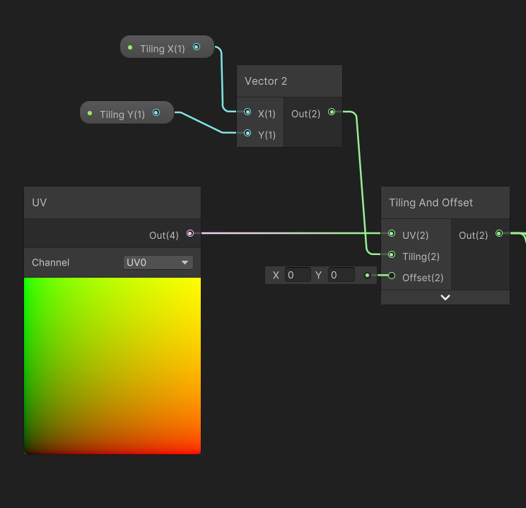
Can render using stencils to prevent those pixels doubling up, e.g.
Stencil{
Ref 1
Comp NotEqual
Pass Replace
}
Or do a prepass rendering to depth only (ZWrite On, ColorMask 0)
Yes. And can set float properties to Slider under the Node Settings tab while the property is selected if you haven't already. If that doesn't do what you want, you'll need to clarify.
Hi everyone, I found an issue in my water shader. Everything is fine but... Something strange happenes on the left corner, there must be something wierd with normals, they are too like some of them even reflect to the "ground" of skybox, nothing of that happennes in any other corner and it does not depend on lights position or rotation. Signs for pictures: 1. left corner is brighter than right. 2. correct situation for normals. 3. wrong corner situation. 4. Shadergraph works with normals. 5. Normals as Base color preview. You can see here left up corner is the problematic one


Thank you friend, will try now.
shader graph?
ShaderGraph can't do stencils. If you're in URP, may be able to use the RenderObjects feature (on renderer asset) to render the layer with those objects on. It can override the stencil operations.
Are the normals going into the "Normal (Tangent Space) port" in the fragment stage?
Yes.
hdrp with shader grpah
my normal map looks like this

I can reach what i want with alpha negative on alpha node but it's not the right solution.. it's like cheating
I don't know if it's causing the issue but as you're overriding the UV coordinates when sampling the texture it may no longer align to the tangent data stored in the mesh.
You should switch the Normal Output Space under the graph settings to World.
Then use a Swizzle node to reorder the normal vector appropriately. (Maybe "xzy" or "yzx"?)
No idea for HDRP sorry. May need to wait for others to answer
any idea of what i can search online?
okay ill try
no it doesnt help
Do fullscreen shaders work in VR?
I have the same issue even with just UV input from vertex attriburtes
problem is with normal map
is there a better channel to put this in, or someone have an idea about this?
i reverted to Beta 11 and it doesn't do it anymore, I guess i will just wait until they fix it in the preview
same shader , same mesh, same material , different unity version


but the cubemap texture reflection is different
the first one looks so dull and printed. where in the second one you can see a beautiful reflection
the cubemap texture import setting is also same
what could be the problem?
well when switching to android , it happens , but i dont know which option actually make this change
does anyone know this?
Have you tried clicking the bake button under Unity's Lighting window? Might be needed to create/update the ambient reflection cubemap
actually it was a problem with the texture format setting
switching to android platform , makes the cubemap texture have different format that doesnt support HDR
Hello i got a little problem with my shader i want to add streng to the normal map but everytime i do that the reflection become messy ! if someone have any solution that will be perfect; ) i am in URP render pipelien if it changer anything !
How are you changing the strength? Can you show in the shader?
I've made (or altered some code I found on unity forum) a blur effect for a full screen shader. It works ok but gets really slow when I set it to be really blurry. I notice the unity dof post processing doesn't have the same problem so I was wondering if anyone knew how that blur works
yes just here ! i have two normal that i blend , and use node graph normal strength for control it ! thank for ur answer btw

I want the middle of fresnel to be transparent. I'm not sure why this is not working

You need to do the exact opposite. Black is transparent. You probably want to pass the fresnel you have directly into the alpha
it just makes the whole thing transparent then
To clarify you want a float for the Alpha port, not Vector4, so would use the Fresnel Effect node output before multiplying by a colour. (Or Split and take A output, if you want it to depend on the alpha component on the colour property)
Result would also depend on the mesh being used
Hey Cyan! Sorry to bother, just currently trying to wrap my head around this whole Custom Render Feature for the same usecase as I've had previously if you remember! Specifically about using "RTHandles" as temporary textures which would be used first in my mask shader, and then my blur shader following. Just wondering if you have any good documentation or beginner instructional documentation I could potentially reference (preferably video but anything works), and if you know how I could even reference my tilemap at all in these custom passes, these two things seem to be pretty challenging for me to figure out. I've been referring to AI for questions and am pretty sure "RTHandles" were not a part of the most recent data gathering haha. (It seems to be making things up), any help or guidance would be extremely appreciated! 🫂
I also have a vertex color with a texture, and if i split the alpha from that multiplication, it correctly makes the transparent parts transparent on the mesh. I don't understand how one float can map the transparency to mesh
You specifically seem like the person to ask based on your personal documentation (which has been extremely helpful)!
Alpha is 1 channel. RGBA textures have 1 channel for alpha. So RGB is a 3 channel color, where A is the transparancy. It is 1 float per pixel, not for the full mesh
What precisely do you think is hard to understand? Maybe I can explain more
Sorry, im new to this, so i just want to wrap my head around it. If A is for transparency, it is a float. But if i take a vertex color multiplied with a texture, split the alpha from it and put it into the alpha on fragment, it makes the transparent parts of the texture transparent on mesh. how can one float make only certain parts transparent?
It is one float per pixel, not 1 float for the whole mesh. So the texture (or shader) can have a different alpha per pixel, telling Unity to render transparancy there or not
I hope I explained it good enough. Shaders are hard to explain sometimes when you are deep into working with them haha
If not Cyan will probably correct me (I see you typing :P)
ooh, that makes sense. Thanks. So if I would want the edge parts of fresnel to be transparent based on texture, and the middle part of fresnel (black) to be fully transparent, how would I apporach it?
Textures are applied onto models using UVs
I would just sample the texture normally, and put the RGB colors to the base color of the shader
Then you can get a fresnel from the normal of the mesh and put that into the alpha (maybe you need to 1 minus it, not too sure on the top of the head. Just know that for alpha black is transparent)
Fresnel only works on smooth curves btw. If you would have a cube fresnel does not really fade at all
I think i figured it out. I multiplied the split alpha from texture, with fresnel and split the alpha again
Thanks man
Hey Cyan! Sorry to bother, just
Can't see anything wrong from a first glance. But, I'm not super confident in normal maps either. The way I would approach is to just use one of the normal maps for testing and see if the unexpected behaviour occurs again. Then test with the other normal node as well. Just to see if the issue is with the way it is getting blended or not.
If it occurs without the blending as well then I would try to use different normal maps and see if it's a texture issue and if that's not the case then I'm not sure what to do next. The normal strength nodes are from Unity and not your custom ones right?
yes that official node from unity ! i am gonna try some stuff like you say thank a lot for your answer and hope that i gonna fix that 😎
I hope you'll find the issue. Would be cool if you let me know what the issue was if you find out.
I swear custom Renderer Features are intentionally poorly documented to cull out the weak minded. (I think I am weak minded), if anyone has any advice or videos which could help push me in the right direction that would be fantastic. I am trying to create a RTHandle of all visible objects with a specific tag (in my case a Tilemap) so that I can use it to mask out a light texture in future passes, if anyone can walk me through that step by step I would be insanely thankful. Or if anyone has any good videos explaining custom renderer feature basics that would be super helpful too!
How do you access the mesh world position inside a shader and not the vertex position
in shader graph, you can add a "position node" set to the world position
If you mean the origin of the mesh, use the Object node
Can I ask Unity to list every single possible shader variant, along with the keywords in each variant, for a specific shader?
I'd like to see where all of my variants are coming from (I suspect I need to clean up my quality presets)
ah, this looks promising https://github.com/needle-tools/shader-variant-explorer
preprocessing produced a 6.5GB file 
@hexed sorrel @regal stag thanks for the response, I am actually not working with shader graphs. Just writing my shader in shaderlab
In that case, UNITY_MATRIX_M._m03_m13_m23 or unity_ObjectToWorld._m03_m13_m23 should work
I wanna apply some displacement to the vertices according to some value sampled from a noise texture. The location of the point in the noise texture depends on the world position of the entire mesh
thanks, I will look into those right now
Hey guys, shadegraph question. I'm making 2d water shader. I have to set it to the highest layer so it covers every object, but it also covers my map borders. Is there a way to detect where are those borders and somehow subtract it from my shader alpha? I couldnt find a way to do this. If not, is there any other way you can think of?

Does anyone know why I can't see the PBR graph in Unity 2021.3?
It was renamed to "Lit Graph"
Was it moved on another window or I have to get a package?

For built-in RP yeah, you need to install the ShaderGraph package via Package Manager window
Thank you!

How do I highlight certain objects in a shader, trying to make a white FLIR/thermla vision shader
That's a very unspecific question. What do you mean by highlighting?
If you want an effect like this, it would be pretty complicated, since there is no infrared spectrum data of the object.

If you just want it all to be one color, you can use an unlit material
RenderFeature (upr) and CustomPass (hdrp) are comparable, so I guess you should not be afraid to check some hdrp repo to compare (at least some DrawRenderer() exemples), anyway I think that your last issue is your pass that don't use a target buffer (by default it should draw to the camera so), you mays are missing something like into your OnCameraSetup: ConfigureTarget(_textureHandle.Identifier());
ConfigureClear(ClearFlag.All, Color.clear);
Okay, thanks! I'll see if that's the case when I'm working on it later, appreciate you!
Unlit material ok got it
is this for 2d shaders too?
Yep! All shaders.
im trying to make a 2d shader to outline all my sprites. but when i put my spritesheet in and switch to quad view its all messed up
I assume shader graph, would you be able to screenshot exactly what you're referring to?
and where or what node you are putting the spritesheet into just to help me get a general idea of what could be happening
@hexed sorrel this is my current shader

i disconnected it from the output because it was messed up
you're gonna need to condense that a little and get a closer screenshot ahah, unfortunately I don't have my microscope with me 

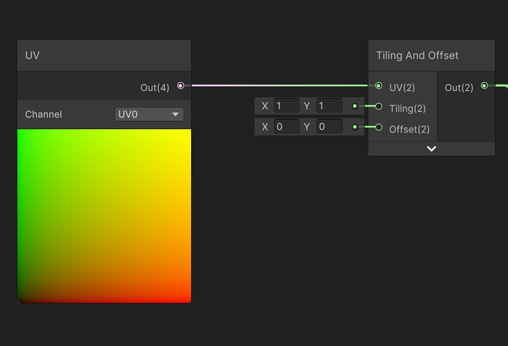
i think the problem is with my spritesheet but idk what it would be
i want to put an outline around my " warrior" sprite
the sprite is animated so the sprite sheet has a few different guys on it
like a little black outline to make it easier to distinguish
mhm! Are you able to show the result of that shader?
a lot of the time the issue is the sprite not having any room for pixels on the sides so it stretches and distorts the sprite.
You should give the sprite some padding if it doesn't already and see if that helps, without knowing much more about your sprites or outputs.
okay thats what the tutorial i said suggested
i just didnt want to redo my sprite sheet if i didnt have to
cause ill prob need to redo a lot of anims, and all my sprite sheets have them directy adjacent
maybe i can somehow use the built in sprite editor to fix it ..
Yep! Unfortunately shader graphs can't leave the "bounds" of the sprite provided, so if it's animated (through the shader graph, and/or the shadergraph tries to leave the bounds) it won't budge at all as far as the size of the sprite goes, I believe this isn't the case for vertex shaders but I could be wrong.
I think you are able to, or use a pixel art program such as aseprite to accommodate for something like that!
yeah okay, are there any other fixs that i should try before i commit to redoing my sprite sheet?
honestly I'd just test expanding the sprite on just that one character and see if that fixes the problem first, and if that works you'll know you will need to look for a way to interpret the sprite sizes differently.
okay
I really can't seem to find much internal documentation to automating the padding process for sprites, however if you look online it seems like there are a few user-made "Sprite Padding" softwares which automatically batch pad image files.
I want a 4 way lerp in hlsl, 4 colours but instead of the usual case where the full colours are in the corners, I want them to be in the centre of all 4 edges, for example:

bit of a janky hack of the result in photoshop, but full red is at (0.5, 1.0), yellow (1.0, 0.5), green (0.5, 0) and blue (0, 0.5). I'm completely stumped on how to produce something like this
I think I need to get the horizontal gradient and vertical gradient.. then lerp using the max of the x/y and various combinations to get diagonal gradients eh..
Hey🖐️
Am ready to work for you
<@&502884371011731486>