#archived-shaders
1 messages · Page 76 of 1
I do currently pad with 0 and hardcode on both sides yeah
I was just wondering if there's a way to read it from shader side
so I don't have to manually synchronize it if I ever want to change that value
when i try to define UnityPerDraw buffer it says that im redefining it, but i cant access it
Afaik it's not possible
there is some weirdness with URP includes where it complains about redefines, it complains about _Time redefine for me even if I just take their code examples, so I'm not sure, I haven't tried to access UnityPerDraw
If you're using URP or HDRP, UnityPerDraw is defined by the ShaderLibrary code
how to access it?(im using URP)
What do you mean by access it, what are you trying to do?
im trying to get a value with a name "unity_ObjectToWorld"
and also the value should be a matrix
URP usually uses UNITY_MATRIX_M macro instead I think but either should work assuming you've included URP's Core.hlsl too.
If you intend to use it to transform between spaces there's also functions that handle it for you - https://github.com/Unity-Technologies/Graphics/blob/master/Packages/com.unity.render-pipelines.core/ShaderLibrary/SpaceTransforms.hlsl
Or use GetVertexPositionInputs(positionOS); to return a VertexPositionInputs struct containing positionWS, positionVS, positionCS and positionNDC.
where is the UNITYCG.cginc located?
UnityCG.cginc is for the Built-in RP, not URP
oh
how do you even include any of the URP headers without error about redefining _Time ?
You need to use HLSLPROGRAM, not CGPROGRAM
I do
even literally taking example given by unity I get error about redefining _Time
the only way I've been able to fix that is by adding include guards around includes, but it seems to be error is in the headers themselves, they should guard against redefining? it seems to me when compiling unity automatically includes some of the headers but if I don't add includes it complains about missing stuff, it's weird
unity 2023.2 / urp 16.0.6 I think
i have problems because after defining Core.hlsl instead of UNITYCG, it doesnt regonize the return keyword???
what do you mean?
k fixed it
I tried this example and it works fine for me. To clarify is this error within Unity (console / inspector on shader) or just an IDE issue? Some extensions may only be for BiRP.
I'll reply when I get back to the project, for now I had some workaround with include guards, it's similar to what I found here https://forum.unity.com/threads/redefinition-of-_time-error-in-custom-function-node.666085/ but I got it in shaderlab instead of custom function include (which I also use but I mostly write in pure hlsl without unity functions)
this happened whenever I tried to include any of the urp hlsl headers
and the error was in unity console, not in IDE
Mmm yeah. Probably an issue with includes then. Though all ShaderLibrary files should already have guards like that so shouldn't be an issue if they are defined multiple times.
I think the only case where I've seen redefinitions is if you're trying to use a mix of BiRP and URP includes.
It's a little different for ShaderGraph as it has it's own version of the ShaderLibrary too, so you usually need to surround pipeline-specific stuff with #ifdef SHADERGRAPH_PREVIEW to avoid redefinitions there.
The guards around the file itself is also to prevent functions being redefined if you use the same include file in multiple Custom Function nodes.
how to get vertex color in URP ShaderLab?
I think you should be able to add float4 color : COLOR; to vertex shader input and pass it to fragment shader? but I'll see if it works in urp
yeah, it worked
struct Attributes
{
    float4 positionOS   : POSITION;
    float4 color        : COLOR;
    float2 uv           : TEXCOORD0;
};
struct Varyings
{
    float4 positionHCS  : SV_POSITION;
    float4 color        : COLOR;
    float2 uv           : TEXCOORD0;
};
Varyings VertShader(Attributes IN)
{
    Varyings OUT;
    OUT.positionHCS = TransformObjectToHClip(IN.positionOS.xyz);
    OUT.color = IN.color;
    OUT.uv = TRANSFORM_TEX(IN.uv, _MainTex);
    return OUT;
}
half4 FragShader(Varyings IN) : SV_Target
{
    return IN.color * SAMPLE_TEXTURE2D(_MainTex, sampler_MainTex, IN.uv);
}
an example
Would it be feasible to use vertex color as an opacity mask as opposed to a texture? Thought I'd ask before I dived into it
How can i prevent these weird visuals on the bridge? i think it has to do with mipmaps or something related to textures.
I mess around with toon shader by unity technologies i made a script to toggle transparency on and off and change transparency level.. but in play mode those 2 work only when material properties are expanded in inspector and not folded and when i click play it is automatically folded.. but idk why this issue causes bugs
Yeah, mipmaps or compression probably. 2d games typically don't need mipmaps as there's no perspective and textures are usually viewed close to their real size.
First shader any tips
it's not only happening on the bridge, but also all over the place if you watch it closely, it's just that since the bridge has a lot of parallel horizontal lines it's where the 'glitch' is more noticable...
I think it's the result of rendering enlarged pixels on high resolution screen. Maybe you can try to make your bridge lines gap to have a good ratio to your screen resolution.
Or you can try activating pixel perfect option in the camera, but I doubt it will help much
Is there any method for improving the dither node when used as an alpha threshold?
In particular, there is a lot of banding
I have used a srp compatible shader. In frame debugger, it shows just 15 but in stats in profiler, batch count is high.
My characters are 2d spine skeleton and I use a srp compatible shader for them.
If I don't use srp compatible shader and instead, apply standard spine shader, in frame debugger, I see high frame count

is there any documentation on URP shader macros and functions?
other than just reading through hlsl includes
Not sure about the profiler, but stats window is very unreliable in terms of batches count. At least on SRPs.
Afaik the stats window does actually show the amount of draw calls but it just doesn't really matter because SRP batcher isn't meant to reduce the draw call count but rather make them super cheap. The Frame Debugger on the other hand should show the SRP batch count which is different (much smaller) from the amount of draw calls. The SRP batch count is pretty much the amount of different shader variants used so it is more or less useless anyways
Hey, I hope someone can help me out with this. I use URP and I have holes which need to be cut out of a mesh. I am using URP to do this. It seems to work perfectly, but when I look at it from below, from the outside it's also gone and it just looks odd. Is it possible to make this work purely on one face?


Was hoping for this to be possible with a shader. Maybe a stencil buffer. Not really familiar with shaders.
how to get Vertex Color in ShaderLab (URP)?
Can't you just access it via the : COLOR semantic?
didn't I reply to you yesterday?
yes, : COLOR works
oh sry didnt notice
ugh, anyone has any idea how to make prefabs with custom shaders render proper previews?
what do you mean can you show the problem?
yeah, I wrote a raymarching shader that requires a bunch of uniforms, so in an attempt to satisfy the prefab preview I set default values to proprties in shaderlab's proeprty block and to required uniforms in the hlsl
for example the prefab looks like this

(everything is raymarched here)
but prefab preview shows nothing (empty as in "empty object")

the material that I added as a sub-asset to the prefab also has no preview

although the properties with their values are displayed normally in the material inspector

and the shader looks mostly like this:
Shader "New SDF scene (generated)" {
  Properties {
    ...
    [Header (root)]
    _1_root_BlendFactor ("Blend factor", Float) = 0.3

    [Header (root_combine)]
    _1_0_root_combine_BlendFactor ("Blend factor", Float) = 1.0

    [Header (root_combine_sphere)]
    _1_0_0_root_combine_sphere_Radius ("Sphere radius", Float) = 0.084241

    [Header (root_GameObject_minus_box)]
    _1_2_1_1_root_GameObject_minus_box_BoxExtents ("Box extents", Vector) = (1.888734, 0.751022, 0.5, 0.0)
    // ... and others
  }
  SubShader {
    Tags {
      "RenderType" = "Opaque"
      "Queue" = "Geometry+1"
      "IgnoreProjector" = "True"
      "LightMode" = "ForwardBase"
    }
    ZTest [_ZTest]
    Cull [_Cull]
    ZWrite [_ZWrite]
    Pass {
      HLSLPROGRAM
      #pragma target 5.0
      #include "UnityCG.cginc"
      #include "Packages/me.tooster.sdf/Editor/Resources/Includes/raymarching.hlsl"
      #include "Packages/me.tooster.sdf/Editor/Resources/Includes/util.hlsl"
      #include "Packages/me.tooster.sdf/Editor/Resources/Includes/operators.hlsl"
      #include "Packages/me.tooster.sdf/Editor/Resources/Includes/matrix.hlsl"
      #include "Packages/me.tooster.sdf/Editor/Resources/Includes/primitives.hlsl"
      #pragma vertex vertexShader
      #pragma fragment fragmentShader

      float _1_root_BlendFactor;
      float4x4 _1_root_SpaceTransform = { { 1.0, 0.0, 0.0, 0.0 }, { 0.0, 1.0, 0.0, 1.5 }, { 0.0, 0.0, 1.0, 0.0 }, { 0.0, 0.0, 0.0, 1.0 } };
      float _1_0_root_combine_BlendFactor;
      // ... includes, vertex, fragment shader
      ENDHLSL
    }
  }
}
hi, does anyone know the best way to do something similar to urp "render objects" or hdrp custom pass, but in BIRP?
so with compute shaders, supporting multicompile, why when I put the #pragma multicompile in a cginc file, and then in the origional computeshader file, use #include_with_pragmas cgincfile, it stops any #includes put lower from working?
aka
globaldefines has the #pragma multi_compile DX11
when I do it this way, suddenly functions found in "Materials.cginc" are missing
if I put the #pragma multicompile inside this shader itself instead of the cginc file, its fine though

interestingly, functions found in "commondata" are not producing errors
Are these errors only in the ide or actually coming up when unity compiles the shader?
when unity compiles
im implementing a dithering/pixel shader with URP and i got a nice shader graph setup however when I try to implement it I just get a purple screen and I dont know why
I have an HDRP shader question with a lot of weird restrictions. I'm making a mod, in this mod I am spawning a cube with CreatePrimitive, and setting its material dynamically via script. Because it is a mod, I don't have access to making my own assets, I only have the ability to modify things from script, thus why I am making a material through script.
My end goal is to have the cube only display when it is behind other things. When looking at it directly (when it is in front of other things) it should be invisible. Currently I'm using this code:
        Material m = new Material(Shader.Find("HDRP/Unlit"));
        m.SetColor("_UnlitColor", Color.yellow);
        m.SetInt("_ZTest", (int)UnityEngine.Rendering.CompareFunction.Less);
        m.SetInt("_ZWrite", 0);
        m.renderQueue = 0;
So the cube is unlit, and yellow...but I've been changing those last three values with all kinds of combinations, and it never fails, either the cube is simply invisible, or the cube is "normal" (ie: visible when in front of things, not visible when behind things).
I've tried render queues from 0 to 5000, I've tried ZTest less and greater. I know this is probably possible but maybe the Unlit shader does not support those keywords? I don't know. Can anyone help me out?
I found my problem, for whatever reason _ZWrite was changed to _ZTestDepthEqualForOpaque in this shader. 😐
I think srp does not reduce batch count.
try this one, maybe it can help
https://www.youtube.com/watch?v=y-SEiDTbszk&t=630s

Hey game dev enjoyers!
Here we are: the mighty tutorial about the stencil buffer that I’ve been working on for weeks now. I hope you’ll enjoy it ;)
WARNING: Please make sure to follow the instructions of the “IMPORTANT” chapter (it's only 30 seconds long no worries), otherwise you would not be able to use the stencil buffer.
The shader and ...
But I think the better approach would be using boolean operation at realtime, I think I've seen some implementation somewhere on internet
Thank you! I can definitely learn a lot from this. I'll try to replicate it
Maybe. But regardless, frame debugger is more reliable than the stats window.
Is Anyone around who knows their way with Shaders? I think i am doing a big mistake and i am stuck but cant pinpoint what i am doing wrong.
I got my system setup to write an objects Mesh onto a GlowBuffer in a single Color. I want to use this to build an Effect around the Mesh. To get the Area "around" the mesh, i wanted to offset the input of the Glow Buffer. To get all angles, i offset it 5 times and added the Result together. Looking like the Screenshot. I have the Feeling, there is an easier way. Especially considering i dont want my Colors to overlap and be just a simple flat Orange (the color on the GlowBuffer Texture) and i need to subtract the original object (the non offset version) aswell.

The problem with your approach is that there's no blurring going and and the layers also accumulate together in unexpected ways ending up not looking that good. Is there some specific reason why you are not using the Bloom post processing effect to achieve glow around the object? If that doesn't work for you, I'd assume the best way to achieve that would be to do something similar yourself by rendering the object(/s) into the GlowBuffer as they are and do post processing on the buffer similarly to how Bloom works so you get the appropriate amount of blurring and intensity.
I'm using a custom shader to tile a texutre onto a line renderer, the only problem is that end caps have different UV's so it looks like this. Any way to fix this?

Have you tried to debug the uvs to see what's going on, I would have thought the uvs work just fine for the end caps as well. Have you tried if the uvs work correctly when there's no rounding for the end caps?
Looks like this when there are no end caps

if there's no other solution, you could round the ends in the shader code
Ugh I'm kinda bad with shaders, any directions on how would I do it?
The shader im using right now is made in the shader graph (urp pipeline)
I actually did exactly that some time ago in shader graph. It was just for the TrailRenderer but I'd assume they generate the uvs exactly the same, I'll check if I can find it
That would be really great! 😄
I'll do the wrong thing here now and just paste my .shadergraph file here for you to use because I'm not sure I would be able to explain it anymore (it's some time since I made it). There's still apparently some issues with the shader if you need to look at the end caps from close and from angle ⬇️ . Basically how the shader works is to scale the uvs correctly to get the sphere shape by using the partial derivatives and then get one distance field for the line to get nice anti aliasing effect (which apparently doens't work perfectly)

Hi, I made a black and white mask for the emission input and i want to have a base color as well. My problem is, that the emission mask completely eradicates the base color and i dont know why. I thought emission would just show up on the non black parts. Thanks 😄


I would try a Saturate node before connecting to the T input on the Lerp. There may be negative values affecting the result
I will try, thanks. Yes i used some subtraction and remapping there might be some values wrong i just dont understand.
@bronze cove this is the distance field I talked about (output of this ⏬ node)


Lmao that works, awesome 😄 Thank you man
I'm checking out the shader graph rn! I see that it works for Trail Renderer but for some reeason doesnt work for line renderer

Thsi is just my first step. I currently need the "Area" of the effect marked somehow. Later down the line i want to include a moving powering up effect akin to Dragonball or Jojos Bizarre adventuire.
oh, you are right, it seems to only work for Texture Modes Stretch and Distribute Per Segment. if neither of those work for your texture sampling, I might be out of ideas. now I don't have the time required to figure this out
Oh I see! I'll experiment with it a little bit, thank you!
Hi, I'm very new to shader graphs and shaders in general. If I make an outline shader that applies to all npcs, would I have to manually add a material with the shader to each npc or is there a more automatic way of doing so?
And what if I wanted to make a toon shader that applies to everything? Would I also have to manually add this shader to each object or is there a way to tell the camera to apply to everything or something like that?
If you use URP, a more automatic way of applying the outline materials may be to use the RenderObjects renderer feature (added to Universal Renderer asset). That can re-render objects on a specific layer with an override material.
As for applying a toon shader, in Forward rendering paths you'd indeed apply this manually to each Material used.
It is technically possible to apply a toon shading to a whole scene using a Deferred rendering path (if the target platform can support it), but that requires a very different shader setup and not beginner friendly.
thanks!
one more question, if I wanted for example to make a shader that changes the colors or add textures to an object, how do I apply this over the toon shading (which, after following a tutorial, requires me to supply a texture/color to it) considering that I only want it to apply on certain objects and not absolutely everything that uses my toon shader (and also considering that I might make a lot of effects)?
Expose another texture for the optional texture in your shader 🤷♂️
hey im trying to create a shader that filters out everything from an inputted texture except the purple. My approachj of subtracting and using compaisons is not working. Is there another way?
ive also tried dotproducting
Can anyone tell me why my Normals look so wrong on Round Surfaces?
Using a fullscreen shader that takes the Normal Vector of the World, multiplies it by 0.5f and then adds 0.5f, shouldnt my sphere look smooth ?

can you have a .shader file in URP?
yes

pink is the color of errors in the shader world
try using a simple output color to see if the shader works and then debug from there. I am only using Shader Graph because i dont want to learn HLSL
alr so its pink 😭
so ... means: shaders are working 😄 I mean, they should in URP. Would be a massive downgrade if they didnt.

how do you compare it? you need to take account the rgb ratio for it to work
Like if your purple color is r:1 g:0 b:1, the comparison could be something like
if(g == 0 && r + b > 0 && r/b ≈ 1)
well ig i shoudl clarify can you have standard surface shaders in urp
ah I see, let me try this
just tested this. This works if i use the Shader on a single component but still breaks when i try to use a Fullscreen One. Anyone has any idea why?
Just googled that: From Oct 2020, there are no Surface Shaders in URP.
https://discussions.unity.com/t/how-to-get-surface-shaders-to-work-in-urp/240394
Somewhere in there someone explains how to port your shaders into a URP format tho
Thanks!
ill check it out
always trying to help 🙂
wait im kinda new to this stuff
u can like basically do anything in shader graphs
that u can do in like hlsl right
i guess so? I am not 100% sure if you get the entire options kit of HLSL in Shadergraph .. but so far, everything i tried to do, i got done with Shadergraph
ill give it a try ig 🤷♂️
yeah u can do it
i found a good tutorial
gl 🙂
got it to work 😈
nice, congrats 🙂 im sadly still struggeling 😄
I try to write the result of a Shader onto an extra GlobalTexture .. .but i dont get it to work with DrawingSettings
I know how to write single renderes onto a specific texture. But how do i write every renderer on a layer onto one? That confuses the hell out of me
hey can anyone point me in the right direction as to how this style was achieved

to me it looks like color quantization with some sort of color palette and some dithering
but im not sure
pretty much this, yeah.
Is there anyway to turn entire sprite into one solid color with shader graph?
yeah, iterate over the sprite. If R+G+B > 0, draw your given Color.
can I just take the ceiling in the shader graph?

should work, yeah.
if that game was using a color palette for the grayscale how come some objects with similair lighting seem to have different colors for e.g. the radios on the left
im guessing its not grayscale...
there are probably more post processing effects at work
its hard to pinpoint ... usually, i would recommend: find the dev on twitter and ask them 😄
i dont know what I did but this worked for some reason

what does predicate really do?
A bool check basically
It defines whether to output the value of True or the value of False. If you give it a float value, I’d assume it does value >= 1.0 or something similar
Could be !=0. Depends on the platform I guess. Some would consider even negative numbers as true afaik.
Mornin' all,
I'm messing about with a 'curved world' shader I found a video for. I'm trying to modify it so the 'curve' starts at a distance in front of the camera, now I've got that part working (currently the curving starts at 20m in front of the camera which is great, but it also curves 'behind' that position (pic attached for context).
I'm trying to figure out how to stop the curving 'behind' that point (so that the tunnel is straight between the curvature start point (20m in front of the camera) and the camera's position (0,0,0)


Can anyone help me out?
In Shadergraph, i need a Subgraph with 4 Inputs and 1 Return value that returns 1 if any of the inputs are non Zero, and returns 0 if all are Zero.
This sounds so basic but i am struggeling with it a lot.
I think, 4 branch nodes, (true/false as 1/0) add them all together, Comparison node set to greater than 0, another branch node with true/false set to 1/0 as your output?
You may need comparison nodes going into your 4 branch nodes?
i am inputting Vector4s, so i need to combine them down ... somehow i am really confused by t his.
okay, gimme a sec
Really not sure if this will work if honest, I'm really not very experienced with branch nodes etc. (ie, not 100% how the predicate input works. :-/)

So basically you're taking in your Vector4 and splitting it into it's component parts and checking if there's a value greater than 0 in each part, then adding all of those 1's / 0's together, and then checking if the final value is greater than 0, which then goes into the final branch, leaving you with an output value of either 0 or 1, which you can check in your main shader graph using another branch. Again I think
I'm currently working on a local multiplayer in a TRON like world. To bring the world more to live I want to create create a glitch effect on a text mesh pro text. My idea was to write a pixel displacement shader on top of a text mesh pro shader. Would that be a good idea and how could one go about implementing pixel displacement in a text mesh pro shader? Is that even possible?
Is there any way to modify URP shader to built in shaders? or to use VAT on that RP?
I don't think you can convert 'back' to Standard Shader, only Standard to URP/HDRP 😕
I haven't watched this properly, just skipped through, so I don't know how relevant.....
sorry, got distracted by a call. I am back now 🙂 let me quickly read up on it
the thing that shcoks me the most is ... there are actual branch nodes ... i tried to solve it by multiplications and stuff but this makes it a million times easier
Yeah from what I understand the branch node is basically an If statement
that makes the problem trivial
nice, thank you! You helped me a ton!
Thank you for the suggestion! I'm going to take a look at it 😄
Like I said, I might be using the Branch/comparison nodes incorrectly, so mileage may vary. lol.
Cool. 🙂
in the end, it was trivial. But thanks for showing me the right tool to get there! ❤️

Cool. Glad you figured it out 🙂
yeah only one more Step for my Outline to be completed 🙂 Then i have build my own, ready to use, Post Processing Shader using the SRP (Which i fell in love with. Such an amazing tool with so many options, and i only explored it for a day!)
Hehe, nice.
just one more line of code that annoys me
ConfigureTarget(normals.Identifier());
i know ConfigureTarget is obsolete, but i didnt figure out what to use instead so it works the same way
If you want to check if at least one of the inputs is positive, you could also do maximum between A and B and maximum between C and D and then compare the maximum of those two with 0. That would cut the required node count to about half (from 7 to 4 it seems). Obviously if the biggest value of the 4 is more than 0 at least one of them is
this might be even better 🤔 Thanks for the input!
Afaik boolean algebra uses floats anyways on shader side so more than likely doing boolean ORs on shader code wouldn't save any performance either
Could also pack your floats in a Vector4, then use the Any node (uses hlsl intrinsic any() function). Returns true if any of the vector components are non-zero 🙂
oh, yeah, that would be even faster!
Can anyone tell me why the output of this Node is Darker when the alpha is lower even tho i completly ignore the alpha in the output?

This would solve all my issues 😄


and i am simply rendering this output here.
This does not make sense to me ... 😦
i think the problem is that the alpha gets multiplied into the color channel at some point ... but i have no clue where 😦 still new to SRP and the texture shown above comes out of a ScriptedRenderPass
As in your rendering these objects with transparency? If so, that isn't just setting the alpha component of the target texture, but doing alpha blending.
its a fullscreen Shader. I put the output Color simply to the value of the three Color channels. Expecting the latest screenshot, but getting the one above.
Where are you changing the alpha?
in the shader that runs in the RenderPass to generate the Texture
So not in fullscreen one right? If that other shader has a blend mode, e.g. Blend SrcAlpha OneMinusSrcAlpha), that's why the RGB channels of the target may also change. That's how transparency works.
i was hoping the 4 channels of the render texture are just 4 Data Streams i could use ... without unity messing with them
and no, the one that renders the texture is not a fullscreen shader
so i guess ...the blending mode here is the issue ?

Basically yea. I don't think ShaderGraph really lets you use Transparent surface type without a blend mode though.
Can maybe try Opaque + Alpha Clipping, just to expose the alpha port and set threshold port to 0. Not sure.
Unsure if that actually outputs the alpha or just uses it for the clip() function though
alpha is either 0 or 1, but the idea was pretty good
so i am stuck at a technicallity thats not solvable ... did i understand this correct ?
May need to use shader code instead of a graph here
ugh, even tho its a graph with just a few nodes. I have no clue how to write HLSL code ... and exporting the Code out of the Shadergraph is a mess with 1,6k lines
I'm making a mesh via code and want to add colours via code to the faces similar to below. I can see there are vertex colours built in but that puts the colour on the vertices. Is there a way to make just the faces the colour?

writing a UV Map in Code and using a generated Texture (can do that in code aswell) to color it.
would that work with the minimal vertices like above?
Since you're rendering this in a custom RenderPass, you can override the blend state in the RenderStateBlock you pass to DrawRenderers. I haven't tried that before, but if it works anything like stencil state, then it will ignore whatever blend state is specified in the shader/material and use your override instead.
yup
that would be sick
your texture can be 3 pixels in size if you want, one orange, one grey, one blue and set it all up with a proper UV Map. With the number of limited Vertices you got there, shouldnt be that hard.
if i knew what exactly the RenderStateBlock is, i would try it 😄
Are you using DrawRenderers in your custom pass?
context.DrawRenderers(renderingData.cullResults, ref drawSettings, ref filteringSettings);
so i would assume so, yes.
Ok, there's a fourth optional RenderStateBlock parameter which you just need to add. To override the blend state so that no blending occurs, it would look something like this:
var renderStateBlock = new RenderStateBlock(RenderStateMask.Blend)

context.DrawRenderers(renderingData.cullResults, ref drawSettings, ref filteringSettings, ref renderStateBlock);
*edited to simplify.
*actually, the default blend mode is already assigned by the RenderStateBlock constructor.
The mask says we want to override the blend state, and since we don't change the blend state, the default state will be used, which happens to be what we want.
yeah just found that one in the documentation
so, this code "should" work ?
It "should"
you are a life saver! I was going insane. This actually fixes it.
Thank you so very much!
Hello, I'm trying to pack a greyscale albedo texture with its normal map and AO. I have the albedo in red, normal x in green, normal y in blue and ao in alpha. I can't get the normal reconstruct z to work properly so far and am looking for help.
Here I've made a simple shader to compare the reconstruct node with the default hdrp lit shader

But my shader graph normal doesn't work as intended
What am I missing ?
I've added another node to load the default unpacked normal map and the result is indeed different

I'm not sure how to fix that
One thing that appears to be missing is remapping the XY values from [0,1] to [-1, 1]. That's one of the steps of Normal Unpack.
That has to be done before Z reconstruction.
so this is what a comparison for a Depth Comparison looks like ... i was hoping it would be pure white but somehow Unity does weird things, darn!

Ok, I'll try to add it after the combine
Still no luck :/ I've added another branch using a Vector2 instead of a combine since this link (https://danielilett.com/2021-05-20-every-shader-graph-node/) shown such example and the result is indeed different from combine but not the same as the real normal map

Daniel Ilett: Games | Shaders | Tutorials
Shader Graph ships with a lot of nodes. Over 200, as of Shader Graph 10.2! With such a vast array of features at your disposal, it’s easy to get lost when you’re searching for the perfect way to make the shader you have in mind. This tutorial shows you every...
I'll try to change from 0,1 to -1,1 with some multiply and substract node then
That's weird, the result seems to be forced clamped to 0,1?

If I try to replace the subtract node back to the the vector2 X, it stays black the whole way :/
Shouldn't the operation be a simple multiply by 2 subtract 1 to change from 0,1 to -1,1 ?
Yes. You could try using Normal Unpack instead if Normal Reconstruct Z. Then you don't need to remap it yourself, you just need to rearrange the channels so it's like a normal texture. Both (x, y, 0, 1) and (1, y, 1, x) are supported by Normal Unpack.
Hm, still no luck I lose all green and red data, they become black it appears?

I think you may also need to normalize them before unpacking. They look pretty dim to me.

Hm, normalizing the combine does not change anything in the preview unfortunately
The colorspace conversion should happen before the Normal Unpack.
I've tried both actually, the result is the same :/
The main issue is that the unpack makes me lose the red and green channels
Why is that ?
Also, I can't put the colorspace conversion before unpack cause colorspace conversion OUT is a vector3 but unpack needs vector4 and I end up with a black result if I put it first actually :x
Well, black preview might also be negative.
Do it before the combine then, to just convert GB before rearranging them.
Still no luck, everything is black now :x

Or did I mess somewhere ?
You can't compare the result from Normal Unpack with a normal map texture sample. You have to also Normal Unpack after sampling a regular normal map.
But the sample node of the original normal is set to normal and the preview does match

it seems to do the same if I set to "Default" and unpack just after

Don't know what's the context here but in general I don't think this is about unity doing anything weird. It's more likely your graphics card doing "something weird". Those weird things are called floating point calculations which can cause inaccuracies in the result and therefore not end up being exactly equal. For example 0.1 * 3 does not equal 0.3 even on your C# code. Often times you would want to compare whether the values are close enough from each other instead of ==
So I thought I could skip the unpack step by setting the type to normal directly
thats true ... i am just frustrated. I am trying to fix my effect for 9 hours now, i learned a lot but still its messy and i am poking in the dark ... was easier to blame unity
could something like abs(a - b) < epsilon where epsilon is some small number like 0.0001 work instead of a == b?
Oh ok, that's my bad then.
will try that next
The only change that should be happening to XY after unpack is the remap. I've noticed the color is a dark yellow, which would suggest similar RG, near or below 0.5. That's close to or less than 0 after remapping, which would result in black.
Yes, my packed texture does have average grey overall

I've double checked with my original normal that the layer matched and they do

I just moved the red and green from the original normal map to the green and blue of the packed map.
But for this point, I then should be able to compare the final unpack with the original texture like that, shouldn't I? the preview should match if everything goes well ?

If I use the reconstruct node, it seems I don't lose the red and green channel but the result still doesn't match the original while it should

I created a Sub Graph containing the HD Scene Depth node. This is producing a warning
Sub Graph at Assets/Visuals/Subgraphs/Scene Distance.shadersubgraph has 1 warning(s), the first is: Validation: HD Scene Depth Node is not allowed by Custom Render Texture implementation
I suppose this is because I could use this sub-graph in a shader graph that does support custom render textures..?
It was not warning me before I created a sub-graph
aww sad, same result ... i had hope this might work. But i had to run and eat something
I guess its time to ditch my whole idea and solve my Occlusion problem in anotehr way ... there certainly is another way i am sure.
what i tried was, to render the Depth into the Alpha value and check, in my outline shader, if the current ScreenDepth would override the Object and then dont draw the outline. But that didnt work ... that didnt even work a little ... anyone has a better idea?
This sounds like an issue you might face more often than not.
If you want to render your objects to a custom texture but still take into account depth of other objects in the scene, you can configure the render pass to use the camera's depth texture so ztesting still occurs. Assuming render pass occurs after opaques
Something like ConfigureTarget(colorTargetHandle, renderingData.cameraData.renderer.cameraDepthTargetHandle);
this sounds way to easy ...
will try that
so far i have set ConfigureTarget in my Configure method, but i dont have access to the renderingData there, should i change the whole setup code to be inside the Execute then ? Im really confused, its quite the big system
What unity version are you using?
22.3
Should be able to swap that function out for the OnCameraSetup one instead then
public override void OnCameraSetup(CommandBuffer cmd, ref RenderingData renderingData) {
uhm ...
somethings broken ... now my URP Sample Buffer Blit Source returns an empty image and my screen only shows some green outlines (the effect that i want)
Did you change anything else? The function should do the same thing, just provide access to renderingData iirc.
To clarify I meant only replace the function name/params, not the contents/body
wait, let me take a closer look what i changed
            public override void Configure(CommandBuffer cmd, RenderTextureDescriptor cameraTextureDescriptor)
            {
                RenderTextureDescriptor normalsTextureDescriptor = cameraTextureDescriptor;
                normalsTextureDescriptor.colorFormat = RenderTextureFormat.ARGB64;
                normalsTextureDescriptor.depthBufferBits = 32;


                cmd.GetTemporaryRT(normals.id, normalsTextureDescriptor, FilterMode.Point);
                ConfigureClear(ClearFlag.All, new Color(0.0f,0.0f,0.0f,0.0f));

                ConfigureTarget(normals.Identifier());

            }
this i had before
            public override void Configure(CommandBuffer cmd, RenderTextureDescriptor cameraTextureDescriptor)
            {
                RenderTextureDescriptor normalsTextureDescriptor = cameraTextureDescriptor;
                normalsTextureDescriptor.colorFormat = RenderTextureFormat.ARGB64;
                normalsTextureDescriptor.depthBufferBits = 32;


                cmd.GetTemporaryRT(normals.id, normalsTextureDescriptor, FilterMode.Point);
                ConfigureClear(ClearFlag.All, new Color(0.0f,0.0f,0.0f,0.0f));

                //ConfigureTarget(normals.Identifier());

            }

            public override void OnCameraSetup(CommandBuffer cmd, ref RenderingData renderingData)
            {
                ConfigureTarget(normals.Identifier(), renderingData.cameraData.renderer.cameraDepthTargetHandle);

                base.OnCameraSetup(cmd, ref renderingData);
            }
Now i changed to this.
and the later code results in my Screen being blank. I guess i need to learn more about the system before jumping into it using it.
okay, nvm ... its fixed. I dont know why, but i will take a look again another day
how to make a fullscreen shader (i think its called post processing) in unity URP (shader graph)
you generate a new ShaderGraph, set the target to Fullscreen, let me take a lookl
In the Graph, in Graph Settings, the Material needs to be set to FullScreen
Then in your URPAsset_Renderer (idk how its named on your end, you will find it) you can click "Add Renderer Feature" and click "Full Screen Pass Render Feature" (i think thats whats its called), then you put your shader you made there and ... it should work.
@ruby sonnet

Idk, for me its there

what unity versions are u using?
22.3
then i guess thats why
Anyone know what this refers to? I am currently using the 2D URP pipeline, is this only for the standard pipeline?

usually this points towards a not allowed node. Maybe the output of the entire chain ends in a node thats no longer "allowed" because you changed the render target
this node alone just has that note without being connected to any other nodes, however when I connect it to a "Sample Texture 2D" node for example it also greys that out, is the "2D Light Texture" node not for use with 2D URP?
I am trying to create a shader for my tilemap to only display the tilemap's tile texture if there is a light overlapping it, so I need some sort of reference to lights in the scene :/
sadly that oversteps my knowledge about the topic by far 😦 still new
Haha all good, I'm also very new. But yeah if anyone does have any idea on any fixes please let me know!
i just started learning all that today t oo 😄
oh nice, yeah I've only done one large-scope shader prior to create pixel perfect wind physics for foliage
I am trying to do the same thing for lighting now, but this silly little message has thrown a little wrench in my progress ahah.
try asking bing copilot ... that one is quite decent at googling
I really appreciate the suggestion, turns out the node is poorly documented under the "URP" section of the documentation when it is solely a built-in exclusive node.
hello everyone I'm sorry for interupting, I have task to make 3d character and render it in Unity. I have done the 3d model with albedo, roughness, metalic, and normal. But I dont know how to render with unlit shader. Can anyone help me by telling me how to do it properly?

I'm sorry cause I'm new in unity shader
Does anyone know of a way in 2D URP to dynamically reference current lights in the scene in a shader graph? I am trying to only reveal the texture of my 2D Tilemap based on if the light is overlapping it.
you can create a material and change the shader on the material to an unlit shader
when you select a mesh renderer in the scene (or you select a material asset), you'll be greeted with something that looks like this

this is a material on the object you selected (or the material asset file you selected directly)
to "render with unlit" you just switch the shader to unlit

I'm trying to create a shader that is "Always in front" of certain geometry (let's say "Enemy"), but is correctly occluded by everything else.
I have been experimenting with the Stencil Buffer (Something I know very little about). The plan was to have the "Enemy" shader write some unique value into the Stencil Buffer (Let's say "42"). Then have the "Always in front" shader follow conditional logic something like this...
if(the stencil value is 42 and the DepthTest fails)
{
Run the shader
}
else if(the DepthTest passes)
{
Run the shader
}
Looking through the available operation tags for Stencil Buffer in Shader Lab, I'm starting to think that it's not possible to set up this condition.
So my question is:
- Is it possible to do what I'm trying to do?
- If not, how do I achieve the "Always in Front" thingy, but only for certain geometry.
I FIXED IT!! I reported it as a bug because I thought it was one, but it turns it the solution was super simple, it makes me kinda mad. All I had to do was use HD Sample Buffer instead of the Texture2D that SRP and URP uses. Now it works perfectly.

A unity developer found what I messed up and emailed me saying that it isnt a bug, I was just using the wrong sampling method.
That's awesome!! thanks for sharing the fix
Anyone know a good way to offset tiling?
Like say I had a texture that tiles, but every vertical repeat, I wanted it offset on the X axis by a bit
What's the simplest way to have a zone on screen be unshaded?
If the entire game screen has a shader on it and I want a circular area around the player to be unshaded.

Add depth to your project with Highlighter Post-processing asset from Inside GPU. Find this & more VFX options on the Unity Asset Store.
Hi, im getting this burring issue when I add a super low quality image to my material

If i up the resolution it fixes itself to this

but im trying to figure out how to use as little pixels are possible. The mesh has as little vertices as possible and all the uvs are assigned correctly. And its using a PNG image
set the PNG image filter mode to point (no filter), if it still doesnt work, disable mipmaping as well
im getting hard lines now with point no filter and generate mipmaps off

If we've downloaded assets from the Unity asset store that have shaders attached to them, is it recommended to enable strip #line directives for performance?

I've never seen that check box before. What Unity version and RenderPipeline are you using?
3D URP

I'm really not sure what that's about.
If it means what I think it means, then you should probably be careful with it. It kinda sounds like it might rip out all the pragmas and keyword related preprocessor conditions. If I were to guess, I would say that it's probably some sort of optimization to reduce the number of shader variants, in which case it wouldn't affect your performance but might affect your build time.
Sorry I don't have a solid answer for you. I hope someone here knows more than I do.
That's what I'm assuming it is as well but I don't think I'll be messing around with it too much
Hey all I have the most noob question ever. How can I make it so the black and white are then changed to Colour 1 and Colour 2? I've tried replace colour but it's too fuzzy

Also would anyone know if I can recreate this without needing to input a circle texture. For whatever reason ellipse doesn't work with the tiling node
using Lerp node, connect Color1 to A, Color2 to B and the black and white texture to T
Thank you!!
Also would you know any way I can adjust the dot size depending on vertex position (like in this image)?

hey guys, is it possible to make a grid of white dots (filled circles) that only render on approximately vertical surfaces?
the shader should have transparent background
In 3D, while maintaining the circle shape?
That's one advanced stuff, with some forbidden techniques that shouldnt even be named XD
I have seen an article for that, but I havent really tried it (see page 71)
https://cdn.akamai.steamstatic.com/apps/valve/2011/gdc_2011_grimes_nonstandard_textures.pdf
Can I GPU instance this? And if yes, how?
Shader "Custom/DepthMask" {

    SubShader {

        Tags {"Queue" = "Geometry-10" }

        ColorMask 0
        ZWrite On

        Pass {}
    }
}
Possible yea. frac/Fraction on the UVs to repeat, circle SDF and step/smoothstep - or just sample a dots texture. Then mask based on Y axis of Normal Vectors.
Probably need to add a CGPROGRAM/HLSLPROGRAM to the pass, using the instancing macros.
https://docs.unity3d.com/Manual/gpu-instancing-shader.html
That page should show examples for surface shader or vert/frag ones. Though may vary slightly depending on render pipeline. If you're using URP the SRP batcher might already be optimising somewhat too - whether gpu instancing will be more efficient likely depends on how many objects are being rendered with this shader.
I need someone to push my mind in the right direction.
I am currently working on an extended outline shader. What i want to do is, build a big outline (roughly double the size of the model) to be rendered above the model while fading out at the top part of it. I got a lot of it figured out, but i have no clue how to fade it out. Its a Screenspace PostProcessing effect.
Tried to Visualize the effect i am trying to do. Not so easy for me :3

I am currently attempting to create a dynamic lighting system for my 2d game and am currently struggling with light incorporation or alteration through shader graphs. My current objective is to create a shader for my "wall" tilemap where when overlapped by a scene light it will dissipate the light quickly but not block it all-together, so essentially the perceived "falloff" of the light is determined based on if it is travelling overtop my tilemap with the connected shader graph. I think my best bet has to be setting the light to "Multiply using (R) mask" but I am having mixed results with understanding whether or not that is a valid approach. My final goal is a lighting system similar to how Starbound or Terraria light their games without needing to actually calculate block light values and instead just rely on the geometry of the tilemap itself. If anyone has any insights as to how I could approach this ideally using GPU resources through shader graph, or even how I could just dissipate light overlapping with my tilemap that would be amazing, I will attach a labelled diagram below, thanks all!

the final solution will hopefully allow lights in the actual scene to cast through the wall and leave a shape of the geometry they initially passed through, I will give another visual example of what I mean below.

^ my current brain pseudocode is something along the lines of (foreach tileSizeToWorldDistance multiply the light falloff by 0.25 (or some easy divisible based on the light intensity left) until fully black)

This is my current solution however, I honestly have zero idea if this is the right approach to reference overlapping light through the (R) mask, the documentation is extremely limited upon my research unfortunately.
why when I'm making directional light strengh below 100% light is clipping thrue walls? (baked, URP)
like this
example isnt baked but it works same when it is baked
That's what shadow strength does, it fades out the shadows into light
#archived-lighting
so how to make shadows less dark without this effext
You're probably thinking of environmental lighting or baked indirect lighting
Shadow is the absence of light, if you don't want to mess with shadow strength you'll need a source of ambient light
ok thanks
I will compensate for anyone's time helping find the solution this problem has been driving me insane for almost 14 straight hours 
I am available to join in a vc to explain what exactly I am looking to do if it isn't very clear also, or a more in-depth text explanation works as-well!
This is a tricky one! With shaders you mostly wanna think about what a pixel / fragment knows about. In this case - looking at your image - a pixel would probably want to march back to the light source to figure out if it's occluded. It needs to know it's shadowed somehow. Ive got some time and would b happy to help you brainstorm.
That would be more than amazing, I've came up with a few ideas as how to approach it. Some more preferred than others, but again the ones I am pretty certain would work I believe are pretty heavy on the CPU which I am trying to avoid if I can.
My one catch is I dont use 2D in my work! So I dont know what kinds of opportunities you have with a tilemap.
Yeah, that does seem like a common problem with most online documentation on the shader graphs haha, essentially what I am determining is that if I can reference the scene lights in my shader graph, I could probably get my system I am envisioning to work. However when I add a light to the scene even outside the bounds of my tilemap with a lit shader it will blackout completely, I am thinking I need to somehow accomplish what a "lit" shader does by lighting the tilemap without it actually being a lit shader, to change the mask it applies.
Are you in URP?
Sorry for the awful grammar ahah, I have a terrible headache from this whole ordeal
Yes
No worries sounds like stepping away from this for a sec might b a good idea too haha
I think I'm starting to understand tho
Yeah, I'm making food at the minute but if you're available now I am as-well!
Thanks so much, you're the best.
If you'd like my exact scene to replicate I can probably provide you with that as-well.
That would be helpful!
it probably won't save the tiledata so if you want I could also just screenshot the tiledata and you could use the tile palette to just draw a similar testing area also!
its just a nook right ?
Yeah basically.
the scene looks pretty simple just wanted to make sure there's nothing weird in there

don't mind what on earth happened here haha
I am just using a freeform light for testing, I'll send all the light data, although I doubt it'll really help as I've been adjusting it a lot.

this is my current string of hope to not need to add a script to manage lights, if I can somehow use this and calculate the changes to the mask through my shader, that should be all the data I need to make any falloff/dissipation calculations when the light overlaps the tilemap!
I'm thinking this approach may be a bit of a pipedream unfortunately though.
This is all the relevant data for the sprites I'm using minus the texture.

thank you! gonna play around a little and get back to you.
Thank you so much, it truly would be a lifesaver.
this portion is also not all that important, if you can even get so much as just the light to dissipate while travelling over the tilemap that would mean the world.

Also will throw in my current "Improved" shader, although it really isn't very effective haha.
maybe sounds like a stupid question, but how can I make a color node with inputs and not not only outputs?

what are you trying to do exactly? if you're trying to combine colors just use a multiply node
you can create a color node and multiply it with another color to create a new color, color nodes are just for implementing new colors to your branch
thanks!
Gave this some thought and I think the best way to go is actually to use the CPU!
To get this working on the GPU the way that I'm thinking through it I think you'd have to go through some big hoops:
-
Come up with a way to store the transmission of each block.
-
Render the scene with transmission colors to a render texture.
-
The shader -- you would handle this in a fullscreen render pass which would loop over every light that could light a fragment. Then for each light you would sample repeatedly in the texture (how much light was absorbed this step? how much light was absorbed this step? etc..) to figure out how much light a fragment receives by the end of the function. This could end up being pretty slow.
Either way I think you need to come up with a way to store some data in the CPU.
I think the benefit of the CPU is if you used the jobs system you could just iterate through chunks instead of going pixel by pixel.
Sorry if this isn't helpful!
All good! I appreciate the effort, I was thinking that might've needed to happen. My main concern was needing to do all the light updates on runtime, which makes testing quite a bit more difficult and heavily reduces fps in engine generally. But I think either way this was basically the only way haha.
I really do appreciate you trying to find a solution in my weird and finnicky guidelines haha!
Yeah! I dont think there's a good way around it! I was starting to think you could bake the distance from the edge to the center of the chunk.
which you could then use to bake absorption
might still work
haha yeah, I was trying to use a mask on the tilemap which would only be affected by lights used in the scene with the red mask multiply blend mode
and then determine distance based on the difference between the full black mask (0) and 1 for a fully lit mask
but I am not sure if referencing lights affecting a mask is even possible in a shader graph
I wanna make the alpha map smaller. but where the texture touches the edges, it shrinks that part. is there a way to make it just smaller while keeping the edges clear?

I thought that approach was working really well until I realized by coincidence my desired effect was the default for a lit shader haha.
Yeah I kept thinking about the lit shader! Transmission is pretty hard in 3D too.
try to multiply by a value under 1, and see if that works!
isn't the multiplying about the color value? it would make it darker
Yeah, my main problem is I am extremely new to shaders in general so trying to balance an already pretty tough job with unity's really obscure shader graph was really tricky haha
Yeah I think in this case you're looking at a pretty challenging shader problem! might be better to start w/ some simple shaders to get an idea of the constraints.

The Book of Shaders
Gentle step-by-step guide through the abstract and complex universe of Fragment Shaders.
I'm a big fan of the book of shaders for thinking like a shader
Yeah, I've made a few before. I did a pixel art / pixel perfect wind foliage shader which turned out pretty nice.
I was hoping for a shot in the dark to land which would save a ton of performance I assumed! But really who knows haha.
I've never referenced a script in a shader graph before so I was trying to avoid it like the plague haha.
Yeah it can get hairy! but its super useful.
Is it just as simple as having a "LightManager" gameobject in my scene for example and attaching a script that references the tilemap shader material?
and passing in the light positions and intensities?
the whole _variable situation
Yeah that's good practice!
Okay! Sounds good, I really appreciate it.
SetGlobalVector will save you from having to set that in a million materials though
if you end up having lots of things that need to find that light position
Great suggestion! I'll definitely use that.
So would you recommend looping through all visible lights to the camera and passing them into the shader separately or how would that work?
I presume there's a way I could pass all the values as a whole in some way
If you don't have many lights I think that's the way to go. If you do you'll want to find another way to render them since it won't scale to lots and lots of lights.
You can also use arrays to store things. Shadergraph doesn't support it out of the box though.
Nor looping. Probably because when you start to go down those rabbit holes you want to consider other options as well.
(but those are things you can use in shaders)
oof yeah, that's what I was a little afraid of 😅
Yeah that stuff can get nasty in shadergraphs.
You're looking at a pretty challenging problem though.
well I'm not too sure about how I'll end up figuring that out but I'm sure I will eventually haha.
You've probably saved me a few days of work assuming I continued down that path.
The extreme lack of 2d lighting documentation in unity is painful to get started with haha, it seems like a lot of solutions are sort of a DIY project.
yeah! It might be worth looking around to see if anyone online has made what you're looking for especially if you have budget for it. Worth giving some unity assets a shot.
Transmission might b a little niche but 2D lighting is something a lot of people deal w/.
Yeah, true! I really do appreciate all the help I am so very thankful to even just be steered in the right direction as I was quite lost!
np!!
Hey y’all genuine question, should I actually try and buy shaders I need because every shader/texture I’ve needed I’ve just found a shader graph tutorial for free on YouTube
It's good practice to learn to make them, especially since you'll almost always need one or to tweak one!
I guess the only right solution is to make the sprite 1 pixel smaller?
I usually make 3D games so not familiar with the 2D shader
https://github.com/BigDaddyGameDev/Tile-Light-and-Shadows-Like-Terraria/tree/main this is one approach to GPU that doesn't give you super accurate transmission but does a cool job of shadowing!

GitHub
An example of how to drawing Terraria style block lighting and shadows. - BigDaddyGameDev/Tile-Light-and-Shadows-Like-Terraria
basic idea is to blur the shadowed parts and then mix that w/ the light
doesn't give u transmission tho!
Oh thank you yeah! I saw that one, that is quite similar to how Terraria's block lighting system works, however my project is aiming to have lighting more reminiscent of Starbound's system, I'll attach screenshots of the effect I am aiming for! But I really appreciate the suggestion, right now I'm trying to figure out how I should handle a max amount of lights in the scene.


those two give a good demonstration of the effect I am going for, and when the lights are animated themselves it gives a really beautiful effect!
One approach would be to render lights as sprites to a camera and then blur that. Then multiply that with the blurred shadow blocks from before. Then you could have as many lights as u want!
That sounds great! Honestly I have no idea how to pass multiple lights as variables to a shader graph which is my main problem atm.
Ohhh wait, can I reference the camera in the shader graph?
Nono don't bother w/ shaders in this case all you need is a full screen shader that mixes the lights and another one for blurring
You would have a camera that renders the lights
To a render texture
Or some kind of buffer
Then blur that
mhm!
And use a full screen shader to mix it together
would this be more performant than somehow passing each individual light?
It's a tradeoff! There's a big memory footprint involved with storing an extra buffer for lighting
I was trying to figure out how to do that but just passed it off because I assumed it'd be super poor for performance but I honestly had no idea haha
ohh, I see.
It's also not awesome for mobile devices
Which usually want to just do all of the work in one render target and not switch.
I'd imagine u could get away w/ it tho!
As long as u use a cheap blur for the lights
Yeah I was thinking that!
See in my head the most ideal solution would somehow be getting the float data for each necessary variable, (vector3 position, intensity, color) then I wouldn't even need to bother spending the extra resources to blur I could ideally just adjust these variables directly onto the dissipation shader used by my block tilemap.
But again, that seems easier said that done as I've found out haha.
The trick w/ that approach is it doesn't scale well! You kinda end up with the jump between deferred and forward rendering
Where deferred has a big overhead for all of the rendertexture
But let's u use tons of lights
Where in forward you loop over all of them
ahh.
For every material
let me grab an example
if I set them to global values I'd only need to declare all of them once per lighting update frame right?
yeah I was looking into that a bit
for (int i = 0; i < maxLights; i++)
    {
        if (i < lights.Length && lights[i].isActiveAndEnabled)
        {
            lightsData.position[i] = lights[i].transform.position;
            lightsData.direction[i] = lights[i].transform.forward;
            lightsData.color[i] = lights[i].color;
            lightsData.intensity[i] = lights[i].intensity;
        }
        else
        {
            // If light is inactive or exceeds maximum lights, set default values
            lightsData.position[i] = Vector4.zero;
            lightsData.direction[i] = Vector4.zero;
            lightsData.color[i] = Color.black;
            lightsData.intensity[i] = 0f;
        }
    }
void UpdateShaderData()
{
    // Pass light data arrays to shader
    tilemapMaterial.SetVectorArray("_WorldSpaceLightPos", lightsData.position);
    tilemapMaterial.SetVectorArray("_WorldSpaceLightDir", lightsData.direction);
    tilemapMaterial.SetColorArray("_WorldSpaceLightColor", lightsData.color * lightsData.intensity);
}
would something like that be performant do you think?
Very performant to set but you pay for the cost of lighting each pixel for every light this way
So you're limited in the amount of lights you can put in a scene
oh I literally just clued into that
yeah no that makes a lot of sense actually.
I forgot that you'd literally have to get the value of every pixel
Which I think is why so many ppl end up w/ the blur approach
this is rough
not directly but I would like Steam Deck to be supported and potentially switch as options, but it is a very early build so I am really just aiming for a performant solution.
I'm almost certain there's a way that I haven't stumbled across yet, and I am sort of looking for a breakthrough in my shader thought process haha.
if I could just render the lights to a lightmap texture per frame and reference them in my tilemap mask that seems like it could be a valid solution
I've seen use of emitters for tracking player movement for realistic foliage, and I'm sure you could get a lightmap system going in a similar fashion.
That way I can still maintain color, direction, and don't need to be calculating for every pixel.
My only concern is the performance hit of getting a lightmap texture for the area around the player and how fast that is, if it's gpu bound that could be very fast and easier to work with than floats in itself.
Why does my shader work in editor, but not during runtime?

this is editor

runtime

this is my shader
what rendering pipeline do you use?
Urp
yeah honestly I don't know it may very well be an error in code. But I'm also pretty new so I can't really add more than that
its okay, Its all in shadergraph tho 😦
Dang, yeah I'd maybe look to see if you're getting any errors or warnings in your console?
By runtime you mean when you press play? What exactly doesn't work? Is it the plane at the portal entrance?@tawny skiff

Unity Forum
Hi, I have a simple shader from the internet which works good in the editor (Unity 2017), but not really in a build. It is a simple dissolve shader:...
I found this thread and you might be able to gather some useful info from it, seems like they are mostly using built-in rendering but you may see an issue you have stand out from that.
what's the texture you're plugging in therE?
my best guess is that when you're getting into play mode something is up with that texture
i'd try seeing what happens w/ the texture on a simpler material

or see if the shader works w/ a static texture
Guess I'm being ignored...
Take a screenshot of the material at runtime.
We literally have no clue about your setup. Share more details


ya issue seems to be with the texture!
ah...
hmm, thats so weird, the output texture for my camera has the material on it. But when I run the game, it becomes empty
thx 🙂
Is that a render texture? What camera renders it? Is it enabled at runtime?
Material on a camera??🤨
its a render texture *
It should be enabled at runtime because its on the camera beforehand
The render texture reference is lost? It's that what you mean?
Yep, I think im resetting it here
 void Start()
 {
     if (cameraA.targetTexture != null)
     {
         cameraA.targetTexture.Release();
     }

     cameraA.targetTexture = new RenderTexture(Screen.width, Screen.height, 24);
     cameraMatA.mainTexture = cameraA.targetTexture;

     if (cameraB.targetTexture != null)
     {
         cameraB.targetTexture.Release();
     }

     cameraB.targetTexture = new RenderTexture(Screen.width, Screen.height, 24);
     cameraMatB.mainTexture = cameraB.targetTexture;
 }
Yes. Why do you need to assign a new rt? Why can't you use the one you have referenced in the editing time?
I want a plane that matches the screen width and height of a camera
so it changes the UVs to match that (I think)
I was trying to follow this
https://www.youtube.com/watch?v=cuQao3hEKfs&t=550s

Get all Udemy courses for only $10.99: http://bit.ly/BRACKEYSJAN
The link above is an exclusive limited $10 site wide deal that expires soon so... go nuts!
In this video we create a smooth portal effect in Unity!
● Download Shader: https://goo.gl/iKCk1r
● Project on GitHub: https://github.com/Brackeys/Portal-In-Unity
The video is based on th...
I don't see how uvs are relevant here at all.
Do they create a render texture at runtime in the tutorial?
no, But I wanted to create my own shader and put it onto a plane
Does the shader texture need to be called mainTexture?
It depends on how it's defined in the shader.
If it's a unity shader, mainTexture would work, as it just aliasing a string that unity uses to define main textures in their shaders.
I think you should start with inspecting your setup thoroughly at runtime. Make sure that the correct material is modified and the correct rt references are set both on the camera and the material. Make sure that the correct material is used on the plane.
Sounds good
I have a quad mesh that doesnt occupy the full uv space, how can I make a circle that fits inside of the uv perfectly, I would like it to stretch to fit,


or really just trying to apply an outline


Maybe the issue is with the circle radius? Try making it 0.5.
Anything beyond that would go out of the uvs range
Ah, it's not the radius of a cir le, but corners rounding?
If the issue is really with the mesh, you'll need to know the actual uvs is using.
so i embedded my textures and materals into my model and only the shoes and sweater worked


show us you model inspector, there should be more than one material slots there
this looks like #🔀┃art-asset-workflow issue
having a really weird issue... i'm on built-in, 2022 LTS... any idea why all my unlit shaders would just stop working?
they're 100% transparent when i apply them to a renderer, no matter what i tweak
build target is android
In the editor?
ya
Can you share some screenshots with details?
The objects that have the issue, the renderers, materials, other components, scene view, hierarchy, etc
huh... i fixed it i think.
I create a new mat... its just the one material that came with photon
if i set that material to Unlit/Color and apply it to anything, like a cube... its invisible
if i create a new material and use the same shader and apply it its visible
Hi, im trying to figure out the best way to make a customisable road generation tool via creating meshes via code. So far I have it so each part of the road (maybe 2 lanes one way, divider in the middle, 1 lane the other way) is generated into one mesh like below. Only issue is that texture colouring of it only works if the texture is very high resolution else it does a weird banding. The colours in the image is green for a lane, grey for a divider, and debug blue/red for divider walls.
I was wondering if I should make each part of the road its own big mesh (each part can have different sizes, eg 10m wide lane vs 20m wide lane) like i currently have. Or if I should be making a template mesh for each part of the road (divider, lane, footpath etc) and join them together. The big mesh would have a custom texture per road (hence trying to have super low resolution textures (in this case it would be 7by1 pixels total)), and the multiple small meshes would have one globally used texture per part of the road.
Or is there a better way of doing this? I would like to stay away from having a GameObjects per part of the road as it leaves gaps between the meshes.

I get these issues when importing the low res textures


Hey! I was having the same issue yesterday and just want to confirm and see if anyone has a good/better solution, in Unity 2D using URP I am trying to get light overlapping the tilemap using a shader to dissipate or travel less far when overlapping it, the current solution is to render lights to a render texture and deal with it that way, however that method isn't very performant unfortunately. If anyone has any better solutions it would be more than amazing, thanks!

My final effect is ideally something similar to the way lighting in Starbound is handled which I will attach images of below.

As you can see light travels quite efficiently until it hits a wall which forces it to dissipate very quickly.
Not something that can be done with shaders, and not something that URP 2D's lighting can do either
Shaders can't get the necessary information about nearby tiles to know whether the light should be dissipating or not
The types of Starbound and Terraria use some variety of a flood fill algorithm (or "flood fill light propagation") I believe
Starbound additionally uses raycasting for certain light types
Ahh, I see. I wonder if there'd be any workarounds possible to even fake dissipation, a lot of examples online use a render texture with blur to fake that sort of lighting, but it doesn't allow for any movement in the lights at all.
if I could even just pass so much as the light's position efficiently, I could just calculate in the block shader how far any given light is and just convert tile size to world size and it'd be a simple division problem. But I really want to avoid having to calculate every pixel. It's definitely a tricky problem.
I don't see why a render texture wouldn't allow lights to move
You can represent a light using a texture, distance function or anything really, but it cannot "react" to environment beyond how it's blended with objects
It's not clear what problem you're solving here specifically
well the general way of using a render texture for this application seems to take all empty tiles and converts them to a render texture and simply adds a blur to fake that dissipating light, I'll get an example of what I am referring to.
URP 2D lighting does give you lights of various shapes and lets you use the resulting render texture in any way you wish
But it has very limited options for shadowing and no light propagation
Is there an easy way to create a render texture with all scene lights and pass it to a given shader?
I've heard that to be quite memory intensive but I definitely think a render texture is going to be my best option
Easy is relative but at least to me it's still unclear why you need to do that and what your lights actually are
I am really just trying to get that same effect as Starbound where the light travels further on the background tilemap and "dissipates" quickly when passing over the wall/block tilemap
You can't calculate light propagation with shaders
But you have various options for drawing lighting without it
Yeah, my plan was simply to use a mask over the blocks where if a light is hitting it, it will reveal it's texture. Which would simulate it being illuminated, in theory.
My only concern with render textures is that I simply haven't used them before and I've been told it's quite computationally demanding, which I am also trying to avoid as best as I can. But again the rest of my game is very well optimized so I do think I have a bit of wiggle room.
This lighting example is quite poor in demonstrating the actual effect I am going for, I tried to clear it up with the markings but it is still likely very hard to understand the effect at all.
Terraria specifically is using a light value which is stored in each individual block which is famously known for being extremely buggy and slow, Starbound seems to be doing something a lot more effective and has a lot better of a look imo.
Hi! In a compute shader, is there a difference between these ways of getting values from a RWTexture2D? A: bool insideMask = InputMask[id.xy] > 0.5;
B: bool insideMask = InputMask.Load(int3(id.xy,0));
Hi all, I was just wondering if anyone knew if it were possible to make a 'screen space' curved world shader? All the guides etc. that I've found are for 'object based' shaders, but for my idea I kinda need it to be screen space due to needing the collisions on the objects etc.
Same thing.
I am wondering if I need to do double buffering
The answer to that is almost always yes.
There are texture types and GPUs that support concurrent read and write, but there's no protection from race conditions.
Group barriers only help in this case if you limit each group to reading within a certain range, and no groups overlap each other.
Oh, the groups would definitely overlap here since the texture is jumping all over the place to flood... Does that mean I should make the loop in the command buffer with ping pong textures, or is there some way of doing it inside the shader?
Have you looked into other compute shader implementations of JFA?
No I did not find one, I implemented one with frament shaders first and then tried converting it
I think the iterations are usually done as separate dispatches, not loops in the shader.

GitHub
Jump Flooding Algorithm with compute shader in Unity - alpacasking/JumpFloodingAlgorithm
I´ll check it out, thank you!
Yeah there was a dispatch loop handling it there
okay so this may seem like a really dumb question and it definitely is, however my tilemap is being affected as separate tiles, and I've fixed this before and I cannot replicate how I know a position node is required but it doesn't seem to be fixing my problem here.


It's likely the 2D Light Texture should be sampled in screen space (so using Screen Position node attached to UV port), but I don't know for sure.
yeah, that did it thanks!
I was just using the wrong position node ahah
In my head, my thinking is maybe a combination of the camera Depth renderer (or whatever it's called) and then offsetting pixels (x/y) based on the depth value? (Shader Graph btw)
Or more likely offsetting vertices ?
I deleted the Library folder and then half of my shaders broke. This black thing appeared. I tried to create a new project and move everything there - didn't help, tried to take an old version of the shader from my repository - didn't help. In the preview in the shader graph - everything is fine. I don't understand what's wrong at all. What can i do?


<@&502884371011731486>
<@&502884371011731486>
!ban 415883320094621696 bot
 mrg3nius was banned.
👍
this is URP 16.0.6 and Unity 2023.2.19f1
Go to you Windows recycle bin and find the library folder, right click it and 'restore', it will put it back from where it was deleted from.
Hey, could someone help me make a shader for trees, what I mean is that the higher the point on a sprite, the more the tree sways left and right, and at the very bottom it doesn't sway at all
I recently did a foliage shader similarly to what you're looking to do, I would first get the "wind" working using a noise map multiplied by time to get it moving, then simply use a texture mask overtop your foliage texture separately.
the mask will prevent any movement on areas that are black and will slowly allow for more movement the closer the mask is to white, you can also use a gradient node if you want a constant vertical black to white mask

Welcome to another devlog for Astortion - a 2D platform-adventure game that I'm currently working on.
Support me on Patreon:
https://www.patreon.com/aarthificial
Unified Interactive Physical Foliage - [UE4 Plugin Out Now]
by Elliot
https://youtu.be/9Fnj5zlcFdQ
UE4 - Tutorial - Interactive Foliage! (Update in Description)
by Dean Ashford
https...
if you'd like he provides his own shader which is open source on github. And allows for interation between the player, do note that it isn't necessarily working out of the box.
Hey, could someone help me make a shader
Hey all, I'm a texture artist helping some friends with a game, but I've never used Unity before. I come from UE5 so Shader Graph is very clunky to me compared to Material Graph in unreal (not complaining about the software, just saying im unfamiliar with it so it's harder). I'm trying to apply my normal map to my asset and I have no idea where it goes. This is in an unlit shader currently, so I get why it wouldn't appear yet, but I just want to know where to plug it in so it's already there when I add my lighting

if there's any good tut's on the process in Unity that's kinda designed for people familiar with UE anyone can recommend maybe?
create a lit shader and at the end there should be a "Normal" input
if I'm not mistaken
I can't do it in unlit? We're trying to get a toon lighting effect so we're planninng to build our own lighting
unless tha'ts just not how it works in unity lol
I honestly am not too sure, I've honestly never used normal maps in my shaders
Yeah I only did it because there's engraving on the revolver and I didn't want it to be topological
Normal maps essentially reflect light based on a 'fake' normal direction, so if it's an unlit shader that doesn't respond to light hitting it, a normal map is irrelevant.

Lit shaders in Unity use physically based rendering techniques to model light as a function of an object's physical properties like smoothness, metallic, and albedo. Learn how to create Lit graphs in Part 6 of this tutorial series!
I'm using Unity 2022.3.0f1, although these steps should look similar in previous and subsequent Unity versions.
--...
Is there a way I can access the normal map information to use in a cel shader?
If you're doing toon lighting in an unlit shader, then you'll have to calculate the lighting yourself. So, ultimately, your normal will probably connect to a Dot Product node to compare it to the directional light direction and calculate Lambert lighting.
this will pretty well explain it
or this
But you need to convert it to world space first.
sounds like a good starting point. I suppose worst case I can always make the engraving purely specular and hand paint it on

it's pretty subtle anyway
thanks gang
Would anyone have any ideas/input please? 😕
what exactly is the final objective you're looking to get?
Project is essentially an endless runner/arcade shooter hybrid where the player is travelling through a twisting/turning tunnel. My current solution is a 'donut' shaped tunnel that is constantly rotating towards the player/camera and 'swings' on it's Z axis giving the illusion of the tunnel twisting and turning, but it's a bit 'boring' and inelegant (if that makes sense).
You won't be able to create a very convincing curve with post processing. See the curve in Animal Crossing.
https://i.stack.imgur.com/L7xZG.gif
Notice how as the trees go behind the curve, you're seeing them from a different angle. You can't get that from moving pixels around.

Yeah, 99% of curved shaders I've seen reference animal crossing. lol.
yeah sorry I really have no idea ahah, I do wish you the best though.
But I was thinking it might be possible to move the vertices instead of the pixels.
I did find one that is great, but because it's object based, when it bends the object(s), the colliders no longer line up .
If you give me a couple of minutes, I'll record some footage.
As long as everything in your scene is curved by the same technique, it doesn't matter that the colliders don't line up. Everything will be "unaligned" the same way, so it looks correct.
unrelated to your question but I'd recommend a program called ScreentoGif or something similar, it makes it really easy to screengrab gifs to use as an example :)
That's the problem, not everything is, the players bullets etc. won't be affected.
I did have an idea to modify the curved shader that I've got to 'start' the curvature at the Z position that the enemies 'sit' when in their formation, but I couldn't figure out how to stop it bending 'behind' that position. (Video for reference)

But, then the problem becomes the collisions with the tunnel.
cool concept!
Thanks 🙂
Started off as a 'Space Harrier' type game. lol.
I'm an 80's kid, so the old arcade games a big deal to me and figured modernising them would be a cool project.
haha, yeah for sure! retro styled games are definitely some of the biggest they've been in a while.
Even came up with an idea (and started building it) where I take 10 'classic' arcade games, use each one as a level in a large story. lol.
that sounds really cool, I'd love to see that!
One option is to disable the collider on the tunnel and handle the collisions yourself with some math. Recreate the curvature math in a script to calculate the path of the tunnel in a few discrete points and for each projectile/bullet, calculate the shortest distance from the path. If any are greater than the radius of the tunnel, they have hit the wall.
That could work, but alas, the radius of the tunnel isn't constant. 😦
Hmm, ah well, I guess my donut solution will do for now.
Hello, could someone help me with the shader, I have 2 problems, the pixels are stretching on the left side, and the sprite is clipping on the right side


you need to adjust your sprite to be larger on the sides to account for swaying
as it can't go outside of it's UV or it'll clip.
I forgot to mention that sorry!
I would add 6~ empty pixels to the sprite and it'll fix all of that!
Thanks, it works perfectly now
happy to hear it!
I'm experimenting with a planet atmosphere shader, but I'm having some issues. If the atmosphere is scaled up to be much larger than the planet, it looks just fine. However, as I reduce the scale (or move the camera closer) , a bunch of really weird artefacts start to appear, and as I continue, the effect just disappears completely. Anyone has an idea why this is happening?


Okay so I've got my cel shader built as you can see in my project shelf, but I already have my model textures applied as a material to my asset. I want to layer the cel shader on top as my lighting, but I'm getting the warning regarding needing to set up multiple shader passes to save performance. What's the best way to do this? Should I be adding a submesh for every material, or should I be adding shader passes to my single mesh?

Hey, really I have a quick question about masking a texture from another (without the "to be clipped" texture needing to be greyscale ideally), in shader graph I would simply like the "Texture 1" (a Tilemap in my case) to clip out the Texture 2 square based on the tilemap's geometry, if anyone has a solution that'd be fantastic. I know it's probably very simple however, I cannot seem to get it to work. Any help or suggestions are welcomed with open arms, thanks! (Picture depiction below).

Ideally the "Ideal Result" texture should be texturally "clipped" so I can use it later on in the shader as a "clipped" texture.
*fixed ideal result screenshot

did ypou find any solution
for shock waves in hdrp
can anyone help with a shock wave radial shader for hdrp
distortion shader seems very difficult to control
hello, so i have a URP project where textures are showing fine, but they turn pink after i build the game
i tried to reset the graphics settings but didnt work, any idea why
if you are changing shader via code, could be that it's not included in the build and need to manually include it in graphics setting
or, if you are building to mobile, maybe the shader contains command thats not supported on the device you are running and I'm not sure if urp provide fallback or not
i built for pc
i didnt change any shader code, maybe it asset related
but if it shows normal in unity editor it should show after building no?
hi! if texture1 has an alpha you should be able to multiply the alpha of texture2 with texture1's alpha
if it doesn't u'll prob need to figure out how to get something like that
another thing you could use in this case is called a stencil

Games like Antichamber feature impossible geometry where multiple objects seemingly inhabit the same physical space, but only appear when viewed from certain angles. We can recreate the effect in Unity using stencil shaders and Universal Render Pipeline's special Renderer Features functionality!
👇 Download the project on GitHub: htt...
if you end up needing to cut geometry out of geometry
based on what you're showing you should be fine just multiplying alphas though
Unity's UI system, for example, is full of logic for stenciling and uses it heavily to mask things out.
but if it shows normal in unity editor it should show after building no?
yeah, if it's on the same PC, I think it's expected to show the same result. Another thing to try is to check for the log in the build and see if there's any warning, other than that, I'm not sure
sounds perfect! Thanks so much.
the second texture (blue in the example) would be a 2d light texture, so I'm not too sure how the alphas work but I'll certainly try that when I'm home!
lmk how it goes!
first time i built i got this errors, the build took a long time to do and failed
second time i got no errors and build was finished quickly, but pink textures ingame

im also curious what the shader is
shaders can be finnicky about platform support
you might wanna try flipping through different graphics apis to see if that changes anything in editor
for the collision, maybe you could just render the depth map, and compare bullet's z position to the z depth on the depth map, but it wont be accurate since the depth would be from previous frame though
Yeah I've looked at a few different solutions, but none are really accurate enough for what I'm doing, especially later in the game when the speed is increased quite a lot. I'm going to stick with my Donut solution for now, it works, so it's all good 🙂
Weird question - Im on unity 2023.2.3f1, and Im writing a "meta" shader for use with the lightmap baker. It seems that the lightmap baker ignores properties set via MaterialPropertyBlock. Has anyone else experienced this? What would the workaround be?
eg: if I set "_Color" to red directly on the material, it shows up in the bake. If I set "_Color" via materialPropertyBlock it does not.
but the scene renders correctly with the propertyBlock color set, as does the preview windows like so


when you dispatched your compute shader you did not set the _SourceVerticies property
check for a typo or set the variable before dispatching
materialpropertyblocks are going out of support, maybe thats the reason
neither urp or hdrp supports them properly
it breaks batching
use separate materials for each object, even if they have totally different variables set
if you create a new material with the old material you dont have to copy properties
var newMat = new Material(oldMat);
i honestly have no clue if this would cause a memory leak in the editor, try setting material.hideFlags to DontSave and call Destroy on the material when the object is destroyed
would be worth to test if this is needed, I just do it to be sure
"breaks batching" is a weird thing for unity to say, because using separate materials also breaks batching
unity has a weird relationship with what a drawcall is >_<'
it does not break the new srp batcher
SRP batching is not drawcall reduction
it lowers cpu usage, which is good for consoles, but its bad for mobile
because mobile wants to reduce the number of actual final emitted drawcalls
which is something materialpropertyblocks let you do
wait could u check my code rq
but it does that too
check rendedoc
or frame debugger
the stats window lies
if you send it here in code blocks like this
sure, thanks for the heads up
(fwiw, you should check what SRP is doing, I think you'll be surprised)
also make sure the shader is srp batching compatible
aren't like the actual drawing commands written in c++?
like I have written custom renderer features but they just use a rendererlist draw command which is then passed over to the c++ black box afaik, could be wrong
Sorry but I can't check that
like is it long?
around 140 lines
ehh why
wait hold up
lemme just look over this
fyi
"The traditional way to optimize draw calls is to reduce the number of them. Instead, the SRP Batcher reduces render-state changes between draw calls."
its not a draw call reducer
which largely sucks for mobile
theres a lot of misinformation about srp batching :/
check renderdoc
if you render the same mesh it will batch
idk if its instancing or what
but it does reduce drawcalls too
it won't combine different meshes
afaik
no
sorry thats bad intel
ill get a cap to test though
yah, SRP doesnt reduce drawcalls


renderdoc says its calling DrawIndexedPrimitive once for each ball (dx11 pipeline)
Urp
and when you look at the frame debugger it says the same thing


Not saying the SRP "Batcher" is bad or anything, its just not actually a batcher
if you want to reduce the number of drawcalls, you have to break SRP Batcher compatibility and use GPU instancing compatibility instead, or manually merge stuff
Is there any way to have Sorting Groups with Opaque objects?
Or is it just impossible given how opaque objects are rendered?
If you have your own srp you can control that
How so?
When you invoke rendering of the opaque part of your scene in a srp, you get to set how it sorts it
Either obeying layers, optimize for batching, using various filters etc
I don’t think there’s any ui for configuring this but the code for changing it (assuming you can locate it for your srp) is just some enums
            RendererListDesc transparentDesc = new RendererListDesc(shaderTagId, cullingResults, camera);
            transparentDesc.renderQueueRange = RenderQueueRange.transparent;
            transparentDesc.sortingCriteria = SortingCriteria.CommonTransparent;
            RendererList transparentRenderList = context.CreateRendererList(transparentDesc);
cameraCmdBuffer.DrawRendererList(transparentRenderList);```so say your srp is doing something like that, you can switch out the sortingCriteria


if you're using the URP or HDRP, the source for this is in the package, just look for "SortingCriteria."
Hi everyone! is there a way to quickly make a scene dark? I want to preview the emission shader settings on a character.
But that leaves an ambient light. If I want total darkness there are more settings I need to press under lighting. I was just wondering of there was another way.
Hey people! I'm working on creating a waving flag as part of the Creative Core pathway, after having completed the Junior Programming part. I have replicated what's in the course (they use PBR, https://unity-connect-prd.storage.googleapis.com/20210406/learn/images/3dd552b7-9e6a-4b2e-990d-6716bdae2821_3_UVnode.PNG) in my project using URP/Lit. Result should be like this: https://unity-connect-prd.storage.googleapis.com/20190819/learn/images/e00116d5-784d-4f5d-917b-002ab9da5561_ShaderGraph3.gif
You'll see my result is very different. Here's a video, and screenshot. Can someone help me along?


Thanks for asking! The flag shader renders in my Scene far away from the flag object. It's not where it should be.
(The white flag GIF is from the tutorial)
you need a world to object node
Either use Object space on the Position node, or add a Transform node to convert from World to Object at the end. Depends what space you want the displacement to occur in
add a world to object position node before the vertex position
Thank you @regal stag and @hearty igloo I will try this now. Just setting the Space in Position to Object makes ripple effect disappear (like in the example GIF). I'll work on the other solutions now.
With object space displacement you'd probably use the R from the position for the Sine setup. I'd assume the B/Z axis is all 0 for a flat plane/quad.
May be some scaling differences too
Yea, can ask any shader based questions here
Good, thanks.
My question: I'm using this nice grass shader https://www.youtube.com/watch?v=MeyW_aYE82s) in my project. It's fine, but I tried to add aspects like the ability to get lit. My problem is that I can't get my grass blades to get lit by additional lights. The HLSL code: https://github.com/HeRobrain3/unityPFI/blob/main/BotWGrass.shader

Breath of the Wild's grass is visually striking and helps to break up large areas of ground. In this tutorial, learn how to make stylised grass just like it in Unity URP using geometry and tessellation shaders!
👇 Download the project on GitHub: https://github.com/daniel-ilett/shaders-botw-grass
✨ Roystan Grass Shader: h...
GitHub
Contribute to HeRobrain3/unityPFI development by creating an account on GitHub.
The grass blades unaffected by point light (flame):

Thank you in advance
Hey folks! Could you have another look at my shader? This is the closest I've gotten to the result I want. But, it's not good. 😅 Video and screenshot attached. And here's that GIF again it's supposed to resemble.

you are moving the vertex on the y axis (vertical), you want x or z
take r or b not g
I think
Can you explain how XYZ relates to RGB?
R=x, G= Y B=Z
try split r to combine r and split g to combine G and split B to add and multiply out to B
I will try, thanks.
If the flag isn't attached to the rod, change the UV split output G to R or B
Thanks. None of that works, or I don't understand what you're saying. I'm going to start over from scratch to get more familiar with the different nodes.
I keep getting this error
Heres my c# scrpit and compute shader

Check the spelling. You use _SourceVertices in C# vs _SourceVerticies in shader
Bruh 😭

try this
wait uh

Since you're using UniversalFragmentPBR it should mostly handle additional light calculations for you. But you will need to define keywords.
#pragma multi_compile _ _ADDITIONAL_LIGHTS_VERTEX _ADDITIONAL_LIGHTS
#pragma multi_compile_fragment _ _ADDITIONAL_LIGHT_SHADOWS
Might be more changes needed too, but that's a start at least.
Thanks will try.
remove the one minus to switch which side the flag stay immobile (fixed to the rod)
but the render mode to both and this is the rotation I used to test the shader :

This is the closest I've gotten now.
Would anyone by chance know how I could take the output of my "Multiply" node and pass it into another group of nodes to create a gaussian blur effect? // I've seen quite a few guides which recommend the tiling and offset node to create a sort of fake blur, however I cannot really pass a "Multiply" node into a Tiling and Offset node even if I were going with that approach. Any ideas would be amazing, thanks!

I found out why, the additionnals light are calculated only in foward+, but foward+ isn't supported by URP. I will try to put the additional light code directly in Pass.
@hearty igloo I tried, but still not exactly what I'm looking for. Thanks so much for keeping helping me.
Not sure what you mean by this. Forward has additional lights too. Also URP does support Forward+ (maybe 2022.2+).
Did you add the keyword pragmas I mentioned?
I tried your shader and It's working for me. try this:
this
"LightMode" = "UniversalForwardOnly" to "FowardPlus" ?
keyword are added
I tried again, but no luck. Can you show me a video of yours?
When I use Tags { "LightMode" = "FowardPlus" }, the grass turn invisble
In short, no - blurring doesn't work that way. Guides that mention Tiling And Offset probably refers to sampling the texture multiple times with offsets, then average them (or use weights similar to gaussian blurs).
Otherwise you'd need to render the result to a Render Texture and apply a separate shader & blit to blur. Though I don't know if that works for your use-case.
Yeah, that is how the Tiling and Offset "blur" was explained, I can real quick pull up full context as to what I am currently working on and what the actual goal is quickly.
ForwardPlus isn't a lightmode afaik. You should stick to UniversalForward
Can't record right now, I'm using OBS to record something, but try my shader in this asset
@hearty igloo Same issue as with mine, I think. Although I've managed to tweak mine to perform better.
And thanks for the continued help.
strange, did you use my prefab and shader? My flags is moving like a real flag.
Ah no, just my own object.
try the prefab and material inside the asset
Yeah, yours is working. I've applied my shader to the existing object in the tutorial so far. I'm going to try with a new plane now.
Yep, New plane with same rotation as my prefab and add the albedo code to my shader graph.
and don't put as child of a scaled or rotated parrent
Thanks I'm going to try that now!
This is the modification I did on my shader and still nothing. Am I missing something?
`Name "GrassPass"
Tags { "LightMode" = "UniversalForward" }
        HLSLPROGRAM
        #pragma require geometry
        #pragma require tessellation tessHW

        #pragma multi_compile _ _ADDITIONAL_LIGHTS_VERTEX _ADDITIONAL_LIGHTS
        #pragma multi_compile_fragment _ _ADDITIONAL_LIGHT_SHADOWS

        //#pragma vertex vert
        #pragma vertex geomVert
        #pragma hull hull
        #pragma domain domain
        #pragma geometry geom
        #pragma fragment frag`
also
this is my URP settings:

For Forward+ you'll also want #pragma multi_compile _ _FORWARD_PLUS
May also need to set normalizedScreenSpaceUV in your InputData struct
I guess lightningInput.normalizedScreenSpaceUV = GetNormalizedScreenSpaceUV(i.pos); in your case
Still nothing, but can you tell my where unity store his base lit shader so I can read it and take my time to find what is missing.
Can find it under the Shaders folder in the URP Package
Mostly Lit.shader and LitForwardPass.hlsl
Nice, I will notify later if I still have issues. Thank you.
does anyone know if it's possible to easily convert a RGBA to a UnityTexture2D easily using custom shaders? I currently have a blur hlsl shader I am trying to use with my light texture after a few passes which unfortunately means it is no longer a "UnityTexture2D" if anyone knows how I could convert this hlsl script to accomodate that multiply output that would be amazing! Thanks in advance.
// void GaussianBlur_float(UnityTexture2D Texture, float2 UV, float Blur, UnitySamplerState Sampler, out float3 Out_RGB, out float Out_Alpha)
void GaussianBlur_float(UnityTexture2D Texture, float2 UV, float Blur, UnitySamplerState Sampler, out float3 Out_RGB, out float Out_Alpha)
{
    float4 col = float4(0.0, 0.0, 0.0, 0.0);
    float kernelSum = 0.0;

    int upper = ((Blur - 1) / 2);
    int lower = -upper;

    for (int x = lower; x <= upper; ++x)
    {
        for (int y = lower; y <= upper; ++y)
        {
            kernelSum ++;

            float2 offset = float2(_MainTex_TexelSize.x * x, _MainTex_TexelSize.y * y);
            col += Texture.Sample(Sampler, UV + offset);
        }
    }

    col /= kernelSum;
    Out_RGB = float3(col.r, col.g, col.b);
    Out_Alpha = col.a;
}

*don't mind the error on the custom function that is just a result of me testing a few things to convert it.
replace the Texture.Sample(Sampler, UV + offset); by a float4 input and add a vector2 as input for the texture size.
I converted my "UnityTexture2D" declaration in the void, with a "float4" which I assume means I shouldn't need to declare "col" at all, so what would I be adding exactly?
void GaussianBlur_float(float4 color, float2 UV, float Blur, UnitySamplerState Sampler, out float3 Out_RGB, out float Out_Alpha)
yep!
color go to Texture.Sample(Sampler, UV + offset)
// void GaussianBlur_float(UnityTexture2D Texture, float2 UV, float Blur, UnitySamplerState Sampler, out float3 Out_RGB, out float Out_Alpha)
void GaussianBlur_float(float4 Texture, float2 UV, float Blur, UnitySamplerState Sampler, out float3 Out_RGB, out float Out_Alpha)
{
    float4 col = float4(0.0, 0.0, 0.0, 0.0);
    float kernelSum = 0.0;

    int upper = ((Blur - 1) / 2);
    int lower = -upper;

    for (int x = lower; x <= upper; ++x)
    {
        for (int y = lower; y <= upper; ++y)
        {
            kernelSum ++;

            float2 offset = float2(_MainTex_TexelSize.x * x, _MainTex_TexelSize.y * y);
            //col += Texture.Sample(Sampler, UV + offset);
            Texture += // ^ undisclosed result
        }
    }

    col /= kernelSum;
    Out_RGB = float3(col.r, col.g, col.b);
    Out_Alpha = col.a;
}
would I need to do Texture += float2 offset?
it's UV plus offset
can you make a wider screenshot of your graph?

essentially my tilemap's texture is above which's alpha multiplies with my light texture's alpha to cut out the overlap from the light texture
can you blur before the multiply?. you blur node will act as sampler
then I reintroduce all color back to the light texture which I am trying to then blur
I guess
Unfortunately no :(
because it needs to blur the "cut out" version
Because I would like the blur to push some of the light texture back over the main texture
I see
Yeah :/
Can't you make the cutout part in code and put it in the guass code, so you can take T2 as input?
Maybe...?
Let me think
in theory I'm sure that route does "work" but I'm sure it would be quite a bit more complicated than converting the unitytexture2d input to a float4, as cutting out then blurring overtop the same texture I started with would be quite confusing to get working I could assume
but if I can't find a solution in this initial route I'll probably need to do something like that
float4 tmp = TextureLight.Sample(Sampler, UV + offset); col += tmp.a * TextureMainTexture.Sample(Sampler, UV + offset).a * tmp.rgb;
maybe?
hmm, it's worth a try!
got an error, I'm not sure this is the right approach.
I'll get a screenshot real quick

line 18: col += tmp.a * TextureMainTexture.Sample(Sampler, UV + offset).a * tmp.rgb;
I'm honestly not even seeing any float3 in the entire script ahah.
other than output*

yes
float4 Texture to t2
You need 2 input texture for light and mainTex, Uv, float blur and a SS.

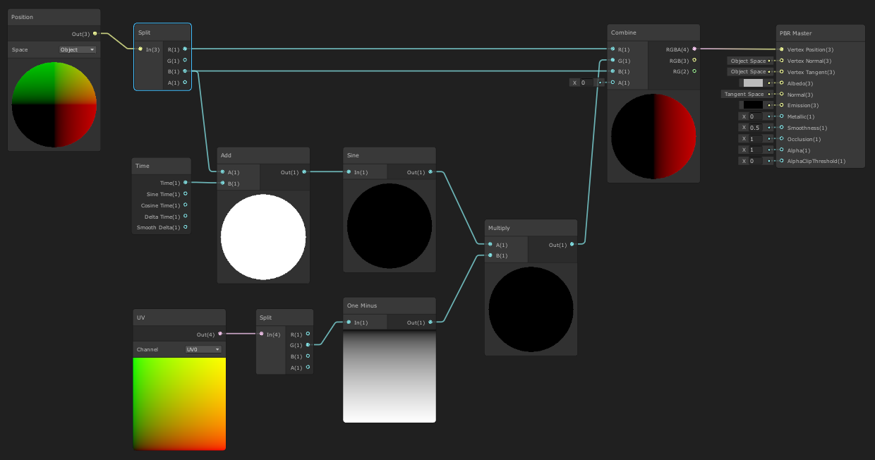
void GaussianBlur_float(UnityTexture2D TextureMainTexture, UnityTexture2D TextureLight, float4 Texture, float2 UV, float Blur, UnitySamplerState Sampler, out float3 Out_RGB, out float Out_Alpha)
{
    float4 col = float4(0.0, 0.0, 0.0, 0.0);
    float kernelSum = 0.0;

    int upper = ((Blur - 1) / 2);
    int lower = -upper;

    for (int x = lower; x <= upper; ++x)
    {
        for (int y = lower; y <= upper; ++y)
        {
            kernelSum ++;

            float2 offset = float2(_MainTex_TexelSize.x * x, _MainTex_TexelSize.y * y);

            float4 tmp = TextureLight.Sample(Sampler, UV + offset);
            col += tmp.a * TextureMainTexture.Sample(Sampler, UV + offset).a * tmp.rgb;
            //col += Texture.Sample(Sampler, UV + offset);
        }
    }

    col /= kernelSum;
    Out_RGB = float3(col.r, col.g, col.b);
    Out_Alpha = col.a;
}
remove texture
the float4?
float4 Texture, it's use less now. right?
well then I'm just completely ditching the cut out light texture no?
now this is just the uncut light texture and main texture
the float4 is a color at a point. you get it via the samplers
Okay wait I'm a little confused, I'll grab my reference images with what I have and where this script ties in, which might help.
Here's what my current shader graph provides

(just the white light is important)
screenshot the error again

and line 18 is?
col += tmp.a * TextureMainTexture.Sample(Sampler, UV + offset).a * tmp.rgb;
I see now
I am trying to turn that first screenshot (what I have) to this:

col += tmp.a * TextureMainTexture.Sample(Sampler, UV + offset).a * tmp;
remove rgb at the end
fixed the error
so if I'm never using the float4 texture how will it know that this is what it should be blurring and not the entire light?
col is still a float4
remove .rgb at the end in col += tmp.a * TextureMainTexture.Sample(Sampler, UV + offset).a * tmp.rgb;
I did this
do you get a out put now?
yes, no error.
but TextureLight.Sample is still my full light ("uncut")
yep
but this is your cut version : tmp.a * TextureMainTexture.Sample(Sampler, UV + offset).a * tmp.rgb
so we're kinda a little where we started no?
where does this reference the cut version if tmp is my "UnityTexture2D TextureLight" which is my full light
float4 tmp = TextureLight.Sample(Sampler, UV + offset); is just to do it once and not twice
tmp = no cut
mhm
and would cutoff be the "Float4 Texture" then I guess?
Hey! I'd like to use Unity to do some offline video processing. More specifically, I want to get a video file, apply a simple shader to each frame, and save the video back to a file. Anyone have any suggestions on how to achieve this? (On a side note, I'm sure there are other, perhaps more suitable, approaches to this. However, Unity's something I know how to use, and due to the project's details, I don't really have the time to learn something new. Despite that, do suggest other tools if you think they're worth it.) Thanks in advance for any help!
tmp.a * TextureMainTexture.Sample(Sampler, UV + offset).a * tmp.rgb would be the texture input for before
if everything work
right but we can't do * tmp.rgb