#archived-shaders
1 messages · Page 71 of 1
the best approach is to pre - blur the cameracolortarget into RenderFeature, you can produce better blurred "cameracolor", set the blurred texture as Global Texture and hop into the shader
then blur it
URP doesn't implement mipmap for scene color like in HDRP, so it's not as easy to blur it. So indeed, you either need to pre-blur, or do a multi tap box blur directly in the shader.
Or just don't care if you only need to distord and not blur 🙂
the way I would have blur in the shader, it is by sampling it multiple time to offset the ScreeUV (old school)
you can sample just 4 time, mulpliying the result and dividing it by the number of textures, whith a little shift in the ScreenUV x or y of each sampled texture(if Léa you need a fast solution it may be easier to do this way), it's less good than the RenderFeature solution however, because if you make a blur by UI element like my exemple: if you have multiple UI element you will have many time the same calculation for each UIelement (per materials), so it's better if all this materials use the same Blurred buffer like by using a renderfeature
is the Object->Screen Transform node equivelent of doing UnityObjectToClipPos ?
it's Object>View I guess
Hello,
is it possible to divide the texture by input colors via shadergraph? For example the texture will have only two colors red and blue and I would like to divide the texture into a part where there are only red pixels and then a part where there are only blue pixels. Next step will be applying adjustments to these parts separately and then merge them together. Thanks a lot! 🙂
If the pixels are fully red (1,0,0) and blue (0,0,1), the R and B outputs on the texture sample node already give you those channels on their own
Ohh, thats true (facepalm 😄 ) and it is possible to somehow divide another specific colors?
Obviously there's the green and alpha channels too. But for other colours it would be a bit more complicated. There's a Color Mask node which can work. For many colours the distance checks that node does might get costly, another option is using various shades in one channel, as the x coordinate for sampling a gradient/palette texture.
This post has some related info - https://www.cyanilux.com/tutorials/color-swap/
thank you for your time and answers! I really appreciate it, i will look into it! 🙂 Have a nice day! 🙂
Someone plz help me, while editing a shader graph the object turned into a default asset and can't be edited or reimported. Ive tried copying, reimporting & reinstalling shader graph idk what to do

I can open it but nothing can be edited to fix
I am somehow utterly failing to recreate this simple vert shader in shadergraph ```v2f vert ( appdata v )
{
v2f o;
UNITY_SETUP_INSTANCE_ID(v);
UNITY_TRANSFER_INSTANCE_ID(v, o);
            float4 unityObjectToClipPos = UnityObjectToClipPos( v.vertex.xyz );
            float4 vertTransform = (float4(v.texcoord1.xy, (unityObjectToClipPos).zw));

            float2 newUV = ( (unityObjectToClipPos).xy + float2( 0.5,0.5 ) );
            o.texcoord1.xy = newUV;

            //setting value to unused interpolator channels and avoid initialization warnings
            o.texcoord1.w = 0;
            float3 vertexValue = float3(0, 0, 0);

            vertexValue = ( (vertTransform * float4( 2,-2,1,0 ) ) + float4( -1,1,0,0 ) ).xyz;
            o.vertex = float4(vertexValue.xyz,1);


            return o;
        }```  This is my attempt to recreate UnityObjectToClipPos

Hi guys, can someone help me with a shader thing ? I know nothing about shaders, and tech art in general, but I would like to give it a try...
So, I would like to create an animated texture in pixel art, frame by frame from a spritesheet, and here is my difficulty : I would like to make it so I could put the texture on any sprite, any shape, any size, without my texture being distorted or stretched, and I would like to try adding a zoom parameter so I can adjust my texture to the sprite too...
I already tried a few things, but nothing worked...
There should be a "ViewProjection" option on the Transformation Matrix node iirc. Just that connected to the A port on the Multiply should do. Model matrix is already taken into account as the Position node is set to World space.
Or could probably use a custom function node to call TransformWorldToHClip
But note that you'll also need to do the inverse after calculating the output position. o.vertex expects clipspace, while shadergraph's Position output in the vertex stage expects Object.
do you have git installed ?
sorry, do you have a git repo for the project*
if so, check what changed
does the asset have the .shadergraph extension?
does asset file contain correct data? (is it perhaps truncated and is 0 bytes now?)
That was my first attempt multiplying world pos by the viewproj matrix and then reversing it at the end. It did not yield the same output as the normal shader
At the end I mul by inverse viewproj and transform from world to object space
What should be the proper way to implement spencil on my shader ?
I just want my UI images to have their own material but also work with UI masking
I think thats what happend
I had to remake everything
why remake, can't you add .shadergraph back at the end?
if you don't use git you should start, because loosing your assets is never fun
funny thing I noticed:
shaderlab mentions Integer property type to be preferred over legacy Int, but Integer doesn't work when used for properties such as _Cull mode
For example in my material property block I have [Enum(UnityEngine.Rendering.CullMode)] _Cull("Cull", Integer) = 0 and later in subshader Cull [_Cull]. Changing value in material inspector doesn't change a thing, but when Int is used instead, it works properly
what's the deal with that?
I'm not sure. But I think float has always worked for ShaderLab commands like Cull. Int is just a float, while Integer is an actual integer. Maybe Cull and similar commands only works with floats, because in legacy, you couldn't define actual integers.
yeah, sadly it's not documented anywhere and it's pretty bad that Int is marked as legacy in the docs, while it is the only thing that works. I wonder how many people had problems with it and didn't even realize...
Float also works. I've always used float for these.
Int is just another name for a float property.
Anyone know a node i can feed that Step into to convert those dots to squares?

Hai,
I made an image effect(full camera) shader in 2D URP, It's working fine with sprites. But it's not working with UI elements.. I want it to affect entire screen including UI.
Try setting the UI rendermode to Screenspace - camera
I think it's a shader thing-- why is this model glowing so hard? It's a .fbx converted in Blender from .gbl for the purpose of making a VRChat avatar, and the .gbl doesn't glow at all

oh. the fbx has a sun for some reason
nevermind. deleted the sun
If you want squares, just use the "rectangle" node.
You can make it tile by using UV -> tiling and offset -> frac as UV input of the rectangle node.
how would you make "speed lines" ?


particles ? line renderer ? material ?
the view is always from top if this can simplify (like on the right screen)
If the UI is rendered as overlay, this is not possible at all, as UI is drawn after everything else, including post processes. You'll have to change the UI to world space - camera to force include it in the camera rendering.
i would just use the shape rectangle and make it repeat a pattern
I'd say particles or a mesh shapped like a "trail" of the ship with a dedicated shader
ok ty
is this possible with shader graph urp ? if so how could I do it
I want to make all canvas elements that overlap with my sprite(the box with black outline) to be grayscaled

I think (not sure) that it should be possible. My guess would be to play around witk masks.
But honestly I think you would not lose much without a shader and just having two object , the colored ones being visible outside mask
Just curious, are there good free alternatives to VHS Pro? Like on github or Unity forums.
At this point I think shadergraphis screwing with me... This is the vs code I'm trying to re-implement in it ``` v2f vert ( appdata v )
{
v2f o;
UNITY_SETUP_INSTANCE_ID(v);
UNITY_TRANSFER_INSTANCE_ID(v, o);
            float4 unityObjectToClipPos = UnityObjectToClipPos( v.vertex.xyz );
            float4 vertTransform = (float4(v.texcoord1.xy, (unityObjectToClipPos).zw));

            float2 newUV = ( (unityObjectToClipPos).xy + float2( 0.5,0.5 ) );
            o.texcoord1.xy = newUV;

            float3 vertexValue = ( (vertTransform * float4( 2,-2,1,0 ) ) + float4( -1,1,0,0 ) ).xyz;
            o.vertex = float4(vertexValue.xyz,1);


            return o;
        }``` and this is the graph so far. For some reason they dont work the same

The decal is being rendered via a command buffer as such ``` public static void RenderDecal(Renderer r, Material projector, Vector3 position, Quaternion rotation, Vector2 size, float depth = 0.5f, string textureName = defaultTextureName) {
// Only can draw on skinned meshes.
if (!(r is SkinnedMeshRenderer) /&& !(r is MeshRenderer)/) {
return;
}
        if (!r.TryGetComponent(out MonoBehaviourHider.DecalableInfo info)) {
            info = r.gameObject.AddComponent<MonoBehaviourHider.DecalableInfo>();
            info.Initialize();
        }
        // Could use a Matrix4x4.Perspective instead! depends on use case.
        Matrix4x4 projection = Matrix4x4.Ortho(-size.x, size.x, -size.y, size.y, 0f, depth);
        Matrix4x4 view = Matrix4x4.Inverse(Matrix4x4.TRS(position, rotation, new Vector3(1, 1, -1)));

        // We just queue up the commands, paintdecal will send them all together when its ready.
        instance.commandBuffer.Clear();
        instance.commandBuffer.SetViewProjectionMatrices(view, projection);
        info.Render(instance.commandBuffer, projector, textureName,projection,view);

        Graphics.ExecuteCommandBuffer(instance.commandBuffer);
    }```
thanks, that is a good idea, and probably cheaper than the shader i wanted to make
Could it be that shadergraph is not getting the view and proj matrices from the cmd buffer ?
I'm not fully sure there with the matrix maths but :
- In the object to clip post group, maybe set the position to absolute world if you are in HDRP ?
- on the right matrix multiple (with inverse view projection ?), you should probably change to input vector to have 1 in W ?
Ive tried option one, yes Im in hdrp. I will now try option 2
how can i fix this ?

Did you add yourself a LOD..... keyword in the graph properties ?
You shouldn't have to care for this one.
Worst case, it's only a warning and you could ignore it ?
Unfortunately that did not work as well. Im starting to really suspect that the viewproj matrix in shader graph is not the one passed to the command buffer
Hello,
I'm sorry, I probably have a stupid question, but I've started making shaders lately. When I have a fragment shader in code version where inside frag function is every pixel modified by the following steps:
-> if the alpha of a pixel is greater than the specified threshold, the alpha is set to the max. value
-> on the other hand, if the alpha of a pixel is less than the threshold the alpha is set to 0
            fixed4 frag(v2f i) : SV_Target {
                fixed4 pixelColor = tex2D(_MainTex, i.uv);
                float opacity = pixelColor.a;
                float3 color_withoutAlpha = (pixelColor.rgb - ((1.0-opacity) * background.rgb)) / opacity;

                if(opacity >=0.5){
                    pixelColor = fixed4(color_withoutAlpha.x, color_withoutAlpha.y, color_withoutAlpha.z, 1);
                }
                else{
                    pixelColor = fixed4(color_withoutAlpha.x, color_withoutAlpha.y, color_withoutAlpha.z, 0);
                }
                return pixelColor;
            }
Is it possible to create this procedure in a shader graph? Thank you! 🙂
I wouldn't even bother to replicate this logic in shadergraph and just use the alpha clip feature

The shader looks good on some rings, but awful and over the top on others
any idea how i can fix this? (The first 2 rings "item flashing effect" look fine, but look what mousing over the third one does)
The output of "Sine Time" is in the -1;1 range, resulting in negative color values, this is what causing the effect.
Connect a remap node between the time and mutliply, set from to (-1;1) and to to (0,1)
You could also use an absolute node instead, but it will make the color animation different
yes i'll just ignore it
but i also got another issue with it, transparency.
I know that unity struggle to hide/show transparent objects when they are in front each other
the thing is, i only got one transparent material, that is applied to one mesh. And i have the issue.
it seems that my sprite renderer placed in BG in considered as a "transparent BG"
but its opaque
what should i change to make it "not transparent" ?

How does this issue appear? Are you working in 2D or 3D?
3D
well, i added my plane and added the material, and when i move the camera at some places and look at my place its not rendered
when I disable the Image comp the issue is fixed
so i think the sprite is considered as a transparent object, conflicting with my plane
this worked, thanks.
Last thing i think and then its (probably) done, how can i make the sine time 'flash faster?'
i tried multiply but its for the colors not the time scale
i forget if i have reply ping turned on, sorry if i didnt
Instead of using directly the sine time output, you can take time, multiply by a speed factor, and input it in a sine node
I set intensity with code:
GetComponent<Renderer>().materials[0].SetColor("_EmissionColor", randomColorHSV * Mathf.Pow(2, 2));
However, why am I unable to observe any alterations in the scene?

HDRP ? If yes, it's possible that the intensity is just not high enough to be visible in the current scene lighting conditions
Hmmmmm so the docs say this about setviewprojectionmatrices “This function is compatible with the Built-in Render Pipeline. It is not compatible with the Universal Render Pipeline (URP), the High Definition Render Pipeline (HDRP), or custom Scriptable Render Pipelines.” So… because the hand written shader is a old CG shader it works… but not for a shader graph shader.
I suppose
Makes sense.
You could also use https://docs.unity3d.com/ScriptReference/Rendering.CommandBuffer.SetGlobalMatrix.html

I can probably also set the two matrices on the material itself. I dont need them to be global since they are calculated per hit.
Turn on bloom if you don't have it, otherwise high intensity just makes things white/higher saturation
So I'm using a Compute Shader that implements Raymarching to simulate liquids with a bunch of physics spheres. It works fine, but it draws over everything in my scene. Is there a way to make things drawn by the ComputeShader render with depth in relation to the rest of the scene?
it maybe the graph that don't get the camera changed matrice as you supposed
did workaround reprojection too few days ago, I had to code my own Unlit, also don't forget GL.Pushmatrix (to push your matrix) and GL.Popmatrix (to restore default)
note in custom pass api now, its far more easy to handle that case (i work hdrp), we have renderfromcamera() and if custom matrix, no need for GL too
the 100 sprite is a circle, but it doesnt look like it on the sprite renderer


the main goal is to avoid having the red circles cuted
since i didnt found a good way of doing this in the shader graph im trying to achieve this in the sprite renderer
Sprite Renderers use the Outline of the referenced sprite to generate a tight mesh around it, changing the texture via shader won't let the Outline adjust
You could instead use texture type Full Rect instead of Tight for it to be a max size quad instead of a mesh
the goal is to have a circle outline
using Full rect would have the same issue
why is the outline correct when unity uses "Sprites-Default" but not others ?
Does anyone custom TextMeshPro shader? I want to custom the Text to has both outer and inner shadow but fail to twist the code cause the lack of shader understanding 😔
I can change use it now, but anyone know how to add new properties and show to editor? I add Properties in script but nothing happen in editor :<<


URP
I don't know why but It fixed with changing priority of material
100% the graph is not reading the correct matrices in hdrp. How would a custom pass replace my command buffer approach?
Shader newbie, trying to make a mesh to terrain blending shader. Would this be the correct way to get the textures from the Terrain layers?

Setup nodes like this, then pass TerrainData from script?
Just curious if there is better way to do it or not
How do you draw the liquid? you can output custom depth in the fragment shader if you draw it on a plane
draw it before transparents too so it stays inside the bottle
remove the custom inspector tag if you have one in the shader, if you copied the default tmp shader it has it's own custom inspector which cannot draw your own properties.
If you want to access these however in the tmpro component itself that probably is not possible unless you edit the package
if sprites default was like your shader it would be bigger, your red circle is bigger than the 100 coin and does not fit inside the 3D model. Reduce the size of the outline, or create a custom outline for your sprite https://docs.unity3d.com/Manual/SpriteOutlineEditor.html
if you create a custom outline you can make your red outline fit inside the 3D model
this example is similar, it just uses intersectors instead of sdfs https://bgolus.medium.com/rendering-a-sphere-on-a-quad-13c92025570c
it has writing to the depthbuffer part
Hi there, what's a good way to create "water fog"?
I was thinking of using the depth of the camera to create said fog, but I am unsure of how it would work
I'm trying to copy how Half Life 2 did it's water shading
personnally I choosed to use the HDRP Custom Renderers Pass shader template in Create>Shader>HDRP Custom Renderers Pass, to move the camera Matrix in custom pass Execute context you'll need: ctx.cmd.SetViewProjectionMatrices(v, projectionMatrix);
Note Uri : HDRP Custom Renderers Pass shader is a single Pass shader that won't draw in the sceneview if you draw to a buffer, so you will need to redraw it into your scene view too
you can use the ShaderTagId to draw only this shader's pass
var MyPass = new ShaderTagId("MyPassName"); ShaderTagId[] shaderPasses = new ShaderTagId[] { MyPass };
as CustomPassUtils.RenderFromCamera() and CoreUtils.DrawRendererList() can both specify a shaderPass to draw it's usefull, it avoid using layermask to render special stuff
yeah thanks , I found that 😆
What do you mean by "reduce the size of the outline" ?
You fundamentally cannot run a shader outside of pixels occupied by its geometry
Sprites are geometry
You need a bigger sprite, or a separate bigger mesh just for the outline
A custom outline cannot be bigger than the full rect of the sprite, which is reportedly not big enough
I see
Thing is I am doing a one off render to a RT, I dont have anything to render each frame with this system @viscid knoll
Hey there,
I have an animated pixel art character. I wish to pixelate the look of the character through a shader (to keep my pixels the correct size as I modify the scale to apply some squash and stretch) . I guess its due to a bad flooring logic (?) but any help would be much appreciated ^^
A: the shader
B: look with
C: Look without


Perhaps you are flooring the exact interesections of the pixels rather than pixels themselves, resulting in ambiguity
Anyway, why pixelate a sprite that's already pixelated?
I modify the scale of the player to give a squishy aspect (instead of animating different level of squish) but I wish to keep my pixels the right size 🙂 It's just a test to see how it looks ^^
Consider if Pixel Perfect Camera component is for you
It'll potentially solve this issue and more in the future
Pixel perfect camera is a bit meh with parralax effect and stutter a lot :/
It has drawbacks in those areas
Old games that were natively pixel perfect did find ways to work around them though, and the same techniques work still
Moving in increments of the pixel values stuff like that (Celeste does that by rounding the values each frame or something like that) but I also personnally prefer if the pixels aren't exactly on the grid. But pixels of the wrong size is still a bit nono ^^"
Then you have made an informed decision!
Regarding this shader have you tried offsetting the pixelation effect by half a texel
In case the issue is that you are sampling the pixel intersections
Dividing will only made the resulting pixels bigger, and multiplying by 2 does create half pixels
I don't mean to offset the pixel grid scale, but its position
Offset the UV by half texel width and height before doing the pixelation to it
Oh right
Well the fucker completely disappear now 😂
hi this might be the wrong channel but i dont know where to ask.
so im trying to make a game looking like a short hike with its 3d pixel look. i managed to get this flat colors but i have no idea how to get the pixel look. i saw this tutorial on yt: https://www.youtube.com/watch?v=1f76ajrdPYc
which is using rendertextures for this, but i have no idea where to add the texture

Wishlist on steam here: https://store.steampowered.com/app/1797850/Goodlands/
Here's how to get that 'A Short Hike' 3D pixel art look -- this is from GOODLANDS, my upcoming indie game where you play as a paleontologist prospecting for fossils in environments inspired by the Montana badlands. Explore a tightly curated open world while interactin...
offsetting by a ridiculmously small value does work though
I'm sure the idea is right, but I always get confused how to get the math and node order right
I believe floor (ceiling and round to) function strangely so might be it
It'll work strangely in pixel intersections for sure
Almost any offset larger than zero but smaller than one texel should do the trick
Exactly half would be best though
Oh well the thing turns out to be ugly so I scrap it. Still learned something so that's that I guess
pls🙏
The idea is: You have Camera 1 looking at the Scene. You put this on a render texture. You can control the resolution of this render texture. You put this texture on a quad. You make Camera 2 look at the quad.
That's the thoery. Don't know how to do it anymore :S
basicly its like playing from another room by putting a kamera in front of the TV? xD
but ty i try
Taht's exactly it
Asking again, but is this the proper way to set up textures from the terrain layers? Just trying to get the first pass/first 4 textures, but wondering if this could be optimized more?

ok i tried know but somehow my "Camera facing the TV to play from another room" (actual name of the gameobject) isnt rendering the tv like its see through
how get I get the scale of the object of the parent ?

my shader is applied to Plane
Shaders don't have access to that data
You have to pass it as a property with a script
so there is no way to get the "real" scale of a object ?
because the "real" scale of the object is the scale multiplied by the parents scale
Create a parameter and divide by it, create a material property block and set the paramater created to the scale of the parent in a script
yup thats what im doing rn
why cant i use my slash shader?

Does your shader have the vfx graph target?
had to fix graph settings
nvm it was just rotated away from the "tv"
I'm facing an issue that my shaders do not render (every pixel is just transparent) on very specific small portion of Android devices, they tend to be very old devices, especially reading tablets which presumably aren't made for games. Otherwise the shaders work fine for everyone else. Unfortunately I do not own such a device to be able to reproduce the problem and debug on my own.
One of the shader is as below which is extremely simple, anything obviously wrong?
Shader "Quad" {

    Properties {
        [NoScaleOffset] _MainTex ("Texture", 2D) = "white" {}
    }

    SubShader {
        Tags {
            "RenderType" = "Transparent"
            "Queue" = "Transparent"
        }

        Blend SrcAlpha OneMinusSrcAlpha
        ZWrite off
        Cull off

        Pass {
            CGPROGRAM

            #pragma vertex vert
            #pragma fragment frag

            #include "UnityCG.cginc"

            sampler2D_float _MainTex;

            struct appdata {
                float4 pos : POSITION;
                float  a   : COLOR0;
                float3 uvq : TEXCOORD0;
            };

            struct v2f {
                float4 pos : SV_POSITION;
                float  a   : COLOR0;
                float3 uvq : TEXCOORD0;
            };

            v2f vert (appdata v) {
                v2f o;
                o.pos = UnityObjectToClipPos(v.pos);
                o.a = v.a;
                o.uvq = v.uvq;
                return o;
            }

            fixed4 frag (v2f i) : SV_Target {
                fixed4 color = tex2Dlod(_MainTex, float4(i.uvq.xy / i.uvq.z, 0, 0));
                color.a *= i.a;
                return color;
            }

            ENDCG
        }
    }
}
What is industry standard? 3d modeling software?
In my opinion it's Blender
Maya ?
Autodesk Maya
Blender
Autodesk 3ds Max
ZBrush
Cinema 4D
SketchUp
SolidWorks
Rhino
Autodesk Fusion 360
Modo
Houdini
Substance Designer
Marvelous Designer
Daz Studio
LightWave 3D
I think that's all
Working on a mesh to terrain blending shader, and I'm having trouble figuring out how to get the normals of the terrain
A lot of those assume that the terrain is heightmap based right? This person reconstructed the heightmap using raycasts which I think is overkill. I'll bet you could just use sample height or the heightmap you used to generate it https://www.reddit.com/r/Unity3D/s/ciYKirO856
From there the process is the same as getting a normal map from a height / bump map.
ah true
Ah wow I'm so dumb. I didn't realize you could get normals from a heightmap. That makes it easier. Thank you
no worries! good luck
are these two expressions equivalent in hdrp?

they should be
im trying to find the depth between the camera and the object being rendered
i read that either of these work, but the bottom one only works in perspective mode
ultimate goal is to create something like this, where the color gets darker with depth

but ALSO so that it doesnt change if you move the camera around (which it does with my current setup)
I was looking at imitating the first shader graph listed here (the power one) https://paulinavfx.com/5-useful-shadergraphs-for-visual-effects-and-game-development-unity-shadergraph/ in order to control the strength of an effect
but I wanted to have control over its color and alpha so I made some modifications.

However, whenever I try to implement the ability to control the color and alpha from vertex color it's disappearing and giving me issues.
Hey there - I fear this will be one of those questions you all see here a lot but I am looking for some quick suggestions on what I can do to fix this. I added URP to an existing project and I believe it's all installed correctly. I'm trying to make my first material for my main character and I have made an unlit sprite shader graph, attached the material to a NEW sprite renderer component and am now looking at the shader graph. I see in tutorials online that people can preview their sprites in the Main Preview window but just keep getting a white box. Additionally my character in the scene is now just a big gray blob with an orange outline.
This is what my shader graph looks like. Any ideas on what the heck is going wrong here?

You don't have a sprite assigned as a default texture, and the mode is set to white
So that's what you get
Thank you vertx, i apologize but can you tell me a little bit about where I need to have a sprite assigned as a default texture? My sprite Renderer does have a sprite assigned. Is there some other place I have to do this setting?

In the default slot in this screenshot
I see, thank you, that seems so obvious now
If you wish to use the sprite assigned here, the Texture2D property must have the name MainTex with the reference _MainTex
Hi. I setup a gradient shader graph and it works fine. I now want to expose different gradients as an enum to drive multiple materials from the same shader. I'm kinda stuck on how to link up the enum to a branch to the defined gradients. Is it even possible?

URP supports GPU instancing, but SRP Batching takes priority over it
SRP Batching is more flexible and in most cases more efficient than GPU instancing
im kinda confused why in shader graphs, all manipulated numbers are between 0 and 1 but RGB colors are between 0 and 255
Colors are 0 to 1 unless you are using the Color32 type, or the color picker in 0-255 mode
so why showing 255

Colo32 is only there for compatibility reasons, I assume
There's no other reason to use it and I'm pretty sure the color picker in 0-255 mode produces a typical normalized Color
okay so its normalized
The color picker cannot change the type of the variable regardless of its mode
Note also that the floating point Color is not restricted to normalized 0-1 range, it can go above it
But that's useful only in case of HDR colors that have brightnesses above 1
okay ty
and by the way
i got this offsetting down using time
how could I make the same effect, but have some "columns" wit hdifferent speeds

i have those columns from this

Different "speeds" meaning?
tiling each columns independtly

or having a pattern
like ABABABABAB
A offsets down and B up
for i.e
If you can find the math for making vertical stripes, you should be able to set their width the same as your horizontal tiling there, and add to vertical UV offset with some multiplier
looks like the image has a portion only of the material
how can I extract a specific area in a texture ?
for example, if I use a font texture, i select a AxB area to select a character
If they're in a grid, you can use the flipbook node
If they're not, you'd have to use tiling and offset with different tiling and offset values for each character
with the flipbook, how do i make it repeat ?
Ah, if you want repeating then you may have to use fraction with remapping instead
okay ill test
is there a way to write a hlsl function that takes vector of any dimension? basically I want a single function, for example sdfSphere(float3 p, float R) { return length(p) - R; } without creating a bunch of overloads for float1, float2, ... etc
do you mind explaining how to use the remap node ?
i quite dont see how changing colors will help
@grizzled bolt - Do you know how materials behave when changing them at runtime?
When i change my material (not at runtime) every copy of my object changes its color. (so far so good)
When i change it via runtime, it creates an instance right?
But it seems, that when i change it at runtime via code, it changed all materials.
Iirc if you use e.g. Renderer.material.color it always creates an instance
If you use Renderer.sharedMaterial.color or Material.color then it modifies the asset for all
By always I mean at runtime
Creating material instances out of runtime doesn't make that much sense so I suppose it instead modifies the shared material when it otherwise would create an instance
There is not.
Great. exactly how i thought!
Thanks 🙂
I'm trying to create a SubGraph and getting this error
NullReferenceException: Object reference not set to an instance of an object
UnityEditor.ShaderGraph.GraphData+GraphConcretization.ConcretizeGraph (UnityEditor.ShaderGraph.GraphData graph) (at ./Library/PackageCache/com.unity.shadergraph@14.0.9/Editor/Data/Graphs/GraphConcretization.cs:33)
Has anyone seen this and have a fix?
FWIW I'm on URP and Shader Graph 14.0.9 and Unity 2022.3.13f1
Hey guys, I need a little help, I've been messing with Shader Graph on my own, trying to get something to work, I didn't find any tutorial specific for what I need, I'll try to explain real quick.
Basically I'm trying to create a shader for a rock that the moss part always stays on top, regardless the rotation
I've done this, probably in the eyes of someone who knows what's doing, this is a real mess of nodes

I want for example this part to always be mossy

@strange berry https://www.youtube.com/watch?v=IC9g5hlfV6o

Let's learn how to make a cool Snow Shader in Shader Graph!
Check out XMLLayout! https://bit.ly/2VZocbu
● The shader is inspired by this amazing video: https://youtu.be/Q43XBychCEY
● Mayan Temple pack: http://devassets.com/assets/mayan-temple/
····················································································
♥ Subscribe:...
Hi... can someone help me add vertical fog to my water shader? This is the current shader code? I'm currently using HLSL, or shader code. However, I'm not sure how to get the scene depth and create a fade effect depending on the depth of the water...
Currently I have it all setup to fade, but I can't seem to like, replicate the vertical fog I need, even online
Can someone help convert this to what I need:
float fog = saturate((SceneDepth - ScreenPos.a) / 10);
https://www.youtube.com/watch?v=X8538W0puoE
I'm following this tutorial

In this video, we will learn how to make a depth fade sub-shader in unity.
Depth fade is needed in many water shaders. So knowing how to make one is essential.
You will also learn the basics of sub-shaders.
Download the Sub Shader: https://github.com/GhostStudiosGS/DepthFadeSubShader.git
Subscribe: https://www.youtube.com/c/GhostStudios?sub_c...
Any idea why does the Tiling And Offset is doing this?
What, doing what they're meant to be doing?
if your texture is set to clamp and not repeat that's exactly what I'd expect
now that makes sense, thanks
Hey Vertx, can you help me with my issue above?
Left: Scene (And what it's supposed to look like)
Right: In Play mode
Why is this happening


hi all, im very new here to shaders. are there people here still writing shader code? I have a really simple question. I want to know how mul4 works
mul ... 4 ?
Hi I am trying to create a small outline shader by offsetting same texture and adding color.. instead of getting pure green as outline, I am getting some yellow patches in between.. why is that ??

can i add lighting to an unlit shader so that it becomes more performant compared to the surface shader?
Anyone??
The unlit shader is performant because it doesn't have lighting
But you can implement your own if you have an idea how to make it more performant
Still, depending on your choice of render pipeline you may have a variety of simpler lit shaders available out of the box, something like vertex lit, lightmap only or simple lit
well, i have already implemented lightmap support on it , but now the only thing i've been trying to add for several months is, to have a single spot/point light (which is real time) affect the gameobject that is using that shader being lightmapped....simply an unlit(formerly ) shader that supports both lightmap and a spot light at the same time
For those pixels where the overlap occurs, you're adding red and green. (1,0,0) + (0,1,0) = (1,1,0) which is yellow.
If you don't want the colours to combine, you'd need to lerp (e.g. using output of clamp in T, texture in A and color node in B) instead of the multiply & add.
If you just need one light then I guess the simplest way is to pass the light's position, direction, intensity, cone and color through properties into the shader and get the dot product from the position to get a very simple kind of lighting
Could you share me a documentation or something regarding it's fucntions and keywords so that I can start implemeting this specific thing inside the shader? Im not used to that lighting thing in shader world
Not working.. I am offsetting same texture and subtracting other from offsetted one to get alpha of outline.. then multiplying outline color to alpha node to get outline
I could tell you how to do it in Shader Graph
I don't think you need any keywords to do it, since every material would support that one light
You just need the properties that can be set from a script, and then do math with them
I see
Hi there
I currently have a Dynamic pixel art water script that simulate pos, velocities and acceleration of an array of virtual points. I then convert this array into a Texture2D (I change the red values of each pixel) per frame that I then pass to the shader in order to convert it back to floats. The shader then make the necessary calculations to draw a pixel art wave according to the resulting float arrays. So far so good my system is working. But as I will inevitably increase the number of water spots and their width, I fear the calculations (that are still handled in script so by the cpu) might take a toll on performance.
The simple solution I see with my limited knowledge is to have the shader to the necessary calculations (e.g. modifying acceleration when a collision occur and use euler integration to update velocities and positions). As I understand, I need to pass a buffer (not sure yet what it is exactly tbh) containing these data.
Is this possible ? Is my reasonnng flawed ? Where can I find helpful ressources on how to proceed ?
Cheers ^^
hlsl variables can be put in namespaces. For example:
namespace vars {
  float someVar;
}

//... later in shader
float tmp = vars::someVar*2;
- Would those variables work as uniforms?
- Can those variables be set with
material.setFloatand others? - Can those variables be controlled by shaderlab properties? If so, how, what's the syntax?
I don't think anyone has ever tried it, maybe not even a Unity developer. I had no idea HLSL had namespaces and it seems to be very poorly documented.
So, just try it and see 🤷♂️
namespaces for functions work quite well. Namespaces for variables however...
as static consts it seems to function
without those modifiers it does not. Glsl compilation fails.
shaderlab can't really parse the vars::someVar in the material property block
How do I essentially sample noise like a clamped texture? Do I just remap the uvs to a 0-1 range ?
To do like a clamped texture, saturate the UV values
Thats what I thought but unfortunately that did not solve my issues. It seems I have a problem with this shader on a fundamental level
Had anyone managed to get branches + gradients to work? If it's not possible, I'll have to come up with something else.
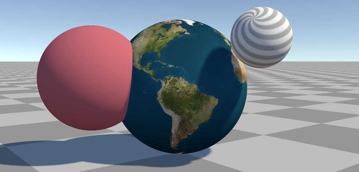
Put a "real" object in there, like a default cube with a standard shader. Do the stars appear over that?
I suspect, although you didn't specify, that your spheres are transparent and not setting the depth buffer. At any rate you'll have to tell us about the objects as well as the particles.
Particles, although they may not set the depth buffer, they should honor it and not write on something they are "behind".
The standard test is LEqual or Less.
But what are the depths of the stars?
I would expect that the stars appear over the two spheres...the purple one is "behind" the star sphere, and the red/pink one is contained within such that stars on the near side of the star-sphere are closer.
Oh, like a skybox?
The camera will draw using a skybox shader between the opaque and transparent passes. This is because transparents must draw over the background. So you should investigate a skybox starfield shader, perhaps rather than VFX. It will be faster.
IDK, I suppose there's other ways. Like generating it on the fly. Here's an example (still a skybox) using URP and Shadergraph:
https://mikeyoung.ghost.io/creating-a-gradient-skybox-with-distant-stars-in-unitys-shader-graph/

MikeLabs
In this example, I'm going to show you how to make a gradient skybox with far-off stars using Unity's Shader Graph.
So I have a scene here involving realtime lights and 2D sprites. When the sprites are in front of a light source, the side facing away becomes dark. This makes sense. Is there any way though to make it so the sprite reacts to a light the same way regardless of direction?
Okay so when I import textures for UI they are always brighter than supposed (also creating color banding on the alpha channel). I am using zero compression, and it only happens when I'm using the Linear color space, on gamma everything works as supposed. It seems a big oversight. Let me know if this is the right thread to talk about this!
I've been searching but I didn't find any solution :(
I'll leave here visual examples of what I'm talking about (linear and gamma respectively):


You can implement custom lighting that skips the part where light intensity is multiplied by dot product of geometry normal and light position
With this if using URP: https://t.co/qQ1JixahQ3
Ya had a feeling I’d need to do that. Thanks for the resources. Hopefully I can do this from a lit graph without much trouble.
Definitely cannot
The default lighting functions are hardcoded into the lit graph
Alright we’ll. Time to light them myself I guess. Surely it can’t be that hard >_>
Right?
You'd have to get Cyan's custom lighting node, modify the normal attenuation out of it, then multiply your texture with that in an unlit graph
Could be worse
Who is Cyan?
Is there a way to ignore partially transparent pixels in shadergraph? I'm trying to recolor this image and I want to ignore the yellow-ish pixels when doing so.


Made the custom lighting node that I linked to you
You can do a step node on the alpha and use that as a mask.
That seemed to work, although its now facing the same issue i'm having with my color adjustment shader.
The shader i'm writing is essentially supposed to replace my grass color with another color, and I do that by creating two patterns that I then add together at the end. The step node worked on preventing the edges from getting color added to them. However Its still darkening the edges which makes me think my color multiply node isn't working as intended.


im new to unity and im wondering why there isnt a option to add emission textures to terrain layer textures and is there a way around it because i know it has somthing to do with shaders? so could someone help me?
Crisis.


@regal stag You this Cyan? Using Unity 2022.3.10f
Crisis averted.
hi all, I'm doing some surface water shader stuff and am using voronoi but it ends up making everything look tiled. Are there any obvious gotchas I'm running into for this sort of thing? I thought the noise would just loop seamlessly

I am using this sub shader, and this is the part where it connects to the voronoi


tyvm for taking a look btw, I really appreciate it
this is my first time going off-tutorial as they say and I'm very lost 😦
I can see the split in the preview itself which makes me think my texture movement shader is causing this
it looks like even a fresh Tiling And Offset node produces this behavior with the built in voronoi noise node. Switching to 3d Preview I am able to see a noticable split in the default settings.

is there some other voronoi node people are using that doesn't produce this behavior?
or am I just really misunderstanding what's going on
from googling around it turns out that the unity voronoi node is indeed not safe for tiling 😦 bummer
is there a way to invert the grayscale of an image nicely?
Sorry for the direct ping but my knowledge of Lighting is actually pretty low. What would I need to do to replicate the regular Lit shader with these node?
wow, googling it and the easiest way is actually to just use photoshop... crazy that shader graph is so powerful but not with everything
Pretty sure like 50% of graphics programming can be solved by a texture.
And another 40% with noise.
well this problem was actually caused by noise!
unity's voronoi generation is not tileable 😦
If a tileable voronoi exists, couldn't you make a custom node to do it?
Ya that's what I ended up doing, I found a big ol png online and used that. But it was in reverse grayscale from what I wanted hence my follow up questions about negating an image grayscale-wise. And that's when I learned its easier to open an image in gimp and press "invert" and save it out since unity apparently has some real troubles with grayscale inversion
So in summary problem solved and my water looks nice
Could also use the One Minus node, no?

BIG
Maybe - I tried a lot of different things. I'll try that too just in case it works
ya one minus on just the RGB (not A) should flip a greyscale.
I'm always happy to learn new stuff in this flow, shaders are so fun
I think
Let me try! The project is still open
well dang! I wonder why I wasn't able to find this by googling around. learn something new every day I suppose!

Hi guys, I was using the shader graph for some uses and I noticed something. For some reason, if I have shader graph installed in my Unity Project, the standard shaders and others break when i choose cutout. Is there any fixes? Because I'm currently using the standard as well
Hi, I have a sprite of a banner. It's showing different in sample2D.. in original sprite, the alpha is like shown in alpha channel (like shown in black and white)
Why is this causing?

Sorry what is causing what?
My original sprite is in shape of that black and white preview (alpha channel preview). But in sampletexture2D it's different...
Shadergraph nodes do not have alpha in their previews. Make sure to look at your sprite in the scene/game view
Right: What it's supposed to look like
Left: What happens at weird angles
Also attached is the shadergraph of the applicable areas. Can anyone help me debug this?


If I may add this only affects play mode, not scene view
What parts specifically would you want to replicate? You are using sprites so it seems unlikely you need every feature
I guess it would be good to know what a "feature complete" graph would look just. Just so if I try some feature in the future I don't get thrown off as to why it isn't working.
Well, a big part is the whole PBR lighting model that handles specularity and fresnel with smoothness and metallic values
For that you'd also need reflections and ambient lighting from the scene and any probes, as well as normal mapping, ambient occlusion and fog
Additionally the Lit Graph for some reason doesn't support Lit shader's features parallax height mapping and detail mapping
At a minimum I'll need the effects active in the video I posted. At least reactive to multiple light sources.
Well, the nodes you showed earlier weren't using any "additional lights", which should be included as a custom node with the package you installed
"Main light" is the brightest directional light
So to get "all the lights" do you somehow combine the Main Light node with the Additional Lights node?
Combine as in "add separately" yes
Is there a reason they're split like this? Optimization?
So these two nodes I assume?

Optimization and the directional light is different enough that it makes sense to have it separate from punctual lights
It's infinitely far away, has no range and no distance attenuation, and it casts shadows from an orthographic perspective
If you have multiple directional lights, I assume that gets bundled with Additional? Like you said, it's the "brightest" directional light?
So what's the normal behaviour here? Add the Color from the Main Light with the Diffuse of the Additional Lights? How does the Normal fit into this normally? Do I dot product the Main Light color with the normal, and then also feed the normal into the Additional Lights?
Sorry for the intensity of the questions here. Just want to get the basics.
"Main light" node has no lighting calculations at all, it's just info about the directional light designated as the main one for you to do whatever with
The Additional lights custom node on the other hand is the lighting calculation part of additional punctual lights, so it can use normal and smoothness inputs
You notice that there is no complete or officially supported workflow to tweak the Lit shader or to recreate it
Alright. So what is the setup here to get regular diffuse lighting from all light sources?
Drag the diffuse output of the additional lights node to your fragment base color input and you'll have that much
What about the main light?
If you don't need normal mapping or specularity you can at simplest do N dot L on the Direction, multiply using Colour and add to Additional Lights diffuse
this?
wait forgot ambient

I think they're the same?

Left = Lit Shader
Right = Custom
Alright now for the big question. How do I get them to be lit the same regardless of the normal?
You'd have to modify the custom function code to skip the LightingLambert function, I believe
Instead use the attenuatedLightColor directly
Alright.
Where is this LightingLambert function defined anyway?
I can swap it out easy (or really just create a new function so I dont break these nodes), but I'd like to see what it does.
for learning
You can double click the custom node to open it up
Inside is another custom node that has the file with the shader code in referenced in the node settings
ya I'm reading the code
Then you can ctrl + f to find it
Doesnt seem to be defined in the file that came with the package. Maybe it's defined somewhere else?
Well it's fine. I should have the info needed to get this working. Thanks for the help.
Are you looking at this "source" file?

how do i get the cone and the position of the light?
You have the position and rotation in the Transform component
You can use a script to pass them into corresponding shader properties
You can get a cone from a direction by getting the dot product of the light transform's forward axis and of the fragment's position
It won't be the exact same as the light component's unless you also pass that data in and remap the result using those, but since you just have one you could define the cone in the shader anyway
As a bonus you can map the result to a curve or a gradient to get any kind of nonlinear light shape you want
I have a HLSL question, is this the right place for it?
that's what i don't know how to do...i am still a beginner in shader coding....i don't know how to get those transforms and use these in the shader properties...
can you help me a bit with this?
Right as I was typing it up I rubberducked myself, I have solved it now 🙂
thankyou though
How to do this in the shader graph Editor In Unity HDRP ?

I was, yes.
If I understood correctly that graph : use the "triplanar mapping" node
https://i.imgur.com/CfdRikw.png
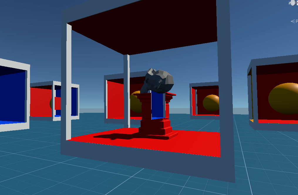
Trying to make some impossible geometry cubes (similar to the game Antichamber) using stencils and I'm running into a problem where if I were to line up cubes nearby, there are angles where my stencil masks overlap, resulting in the correct pixels not being rendered. I was thinking of some dividers between each cubes using some quads, but I'm not exactly sure of the idea behind setting that up.
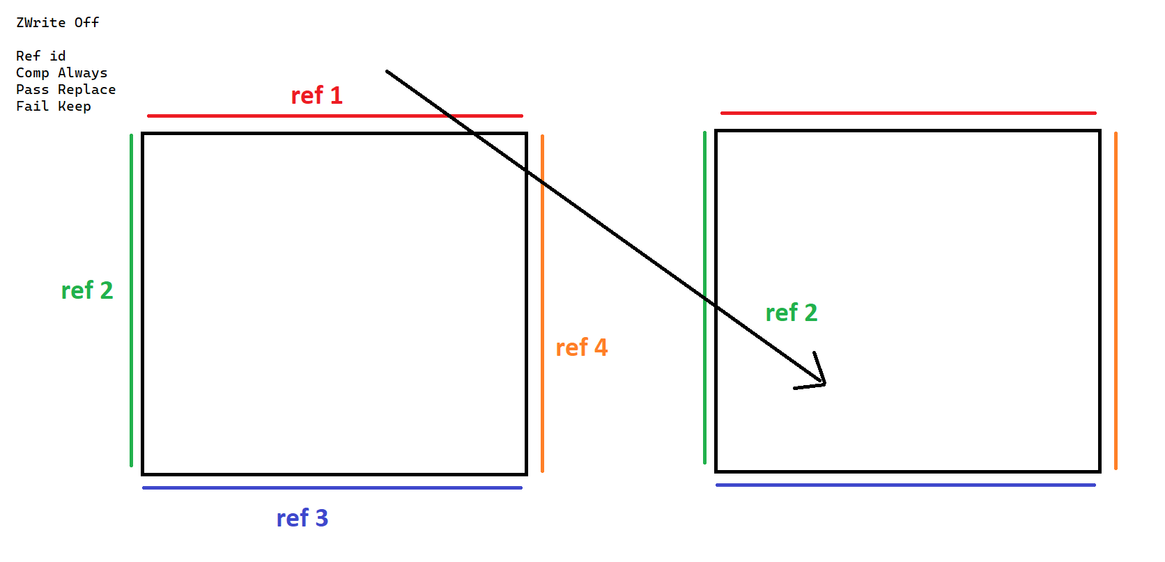
Some ideas that do work is setting some opaque quads with the masks, but this kinda confines the space to the cube, but in Antichamber, the space itself expands way beyond the cubes sometimes.
I can think of other ways too, but this requires using a lot more stencil values / layers but those are greatly limited and I imagine running into other problems that way.
Ok, so it seems that doing the stencil testing after I render my opaques does help me limit how much stencil testing is done. Lining the cubes with a secondary opaque border does limit the range which I stencil test, but I would prefer to have this larger divider outside of the cube so I can expand the geometry beyond the cube itself. So, the problem now is that I'm not sure how I create this divider as creating something transparent and writing to depth seems to create a lot of interesting artifacts. Perhaps there's another way to go about this.
https://i.imgur.com/H4qsrJl.png
Something like this but that wall being transparent. Would this be possible?
Or maybe there's another way I should be tackling this depth issue
Basically it's more of a rendering order issue, but since you can view the cubes from different angles (from and to different cubes) then doing it by absolute rendering order would be impossible, so it looks like I need some type of depth to limit what is being tested as I can't figure out how to do it with stencils alone.
Yeah, not sure. I think there's a lot more masks to be involved which are rendered at different times is my theory. For the most part, it's pretty easy to change what's confined in a space, but when it comes to expanding out that space does it become a problem.
erm, in terms of shader graph:
I use the same effect in a few shaders, and I don't mind duplicating the nodes since it allows me to use shadergraphs without needing any sub-graphs bundled with it.
However, let's say a bunch of nodes generates...1000 lines of code. 2 shaders = 2000 lines, would a sub-graph limit that to 1000 lines? I guess i'm asking if under the hood its more performant to use sub-graphs where possible
Hello,
I would like to create a shader to simulate a projectile.
Problem: what if the projectile goes far from the camera view and with a different angle from comera? I need to see them always and don't want to use meshes or particles or trail renderers. I just need a texture that face the camera. i did it with a script but it does not work fine because it always face the camera .
could anyone help me to solve this?

Can someone help me with this?
Please, I have no idea what's going on
hey fam what's a good way to blend two colors together into some sort of gradiant?
if I lerp between two colors and give it a ratio between a value and the y coords in world space I get a harsh line but I'm looking for something blend-y
I want this but, like, blendy

Hi friends, I am creating a drop shadow shader, the shadow part works fine.
(Offsetting uv and adding shadow color)
I need to add softness/spread to the shadow.
.
What would be the easiest way to do this?

Hi, is there a LightMode in shader pass tag named "DepthNormals"? I have been reading the Docs but cant find anything about it
I know there is a "DepthNormalsOnly", but this one shader im reading has a Lightmode named "DepthNormals" might be a typo?
Oh wait there is one in the Lit.shader
WUT
blur shader
Try the SmoothStep node instead of Comparison
Or InverseLerp, or Remap+Saturate
Hi, so I have a ShaderGraph that creates my water texture, it's ripples, etc. The thing is, idk why, but it doesn't export to mobile. I've built to my Samsung S23+ plus multiple times and I JUST realized the shader isn't showing up at all, although in the game view in Unity, the shader shows up and is correct.
Maybe it's because I'm using URP? I'm not sure. I have no experience with shaders and no clue where to start when it comes to troubleshooting


This is my water on my phone. It seems the shaders solid color is showing, with its alpha value. But the voronoi noise I'm using for the ripples isn't working/showing

Blur shaders are rather tricky to do
I'd recommend pre-blurred sprites/images that are attached with scripts
Guys I'm trying to achieve this effect (top face borders of voxels lit up)
Here is what I've got so far (2nd pic), I am passing vec2s through UV channel, but the blending is pretty bad rn. I am using shader graph, **do you guys have any tips how I could blend it better? ** I just want little part if the edge to be highlighted like in the first pic


Rn it's just UV -> split node to get x & y components -> vector2 -> length -> to lerp T
maybe just create img texture and use that instead?
Did you try the „power“ node? That should make it stronger at the edges
Could be down to mip maps
What do the UV components represent?
Hi, Im trying to make a unlit shader that receives pitch black shadows from other objects. It currently only works with directional lights and I would like advice on how to get it to work with point lights. Thanks
Assuming the voxels DONT move:
you can do this and apply it to the normal vector up:

that should apply to the top face only
and you can use a Lerp node for the blending I believe
like this? https://www.youtube.com/watch?v=oCNhvy_qOp0

Follow along as we develop this mind-bending illusion using Unity and Blender. Expect to learn about the stencil buffer, transparency, and shaders in Unity. Designed with beginners in mind, this tutorial will walk you through not just the how, but also the why.
Github: https://github.com/PerspiringDeveloper/AntichamberTutorial
00:00 Introducti...
vector2 is (0, 0) if effect shouldn't be drawn
if effect should be drawn, it could be (1, 1) or (1, 0) etc depending whether it is corner voxel or not

iirc it was just DepthNormals back in URP v10, but as they also use "DepthOnly" I'd assume they renamed it to DepthNormalsOnly to be more consistent.
Doesn't really matter which you use currently though, they are both taken into account by the DepthNormalOnlyPass.
how to make a bilboard effect in shader graph?
I would like a texture that always face to camera. any idea?
Based on your question you'll want a specific type of billboarding that only orients its depth or up axis towards the camera, while keeping its forward axis unchanged
how can i use a vector as a direction in shader coding?? i understood that if i get the dot product between the lightdirection (using the _WorldSpaceLightPos0 variable) and the normals direction, i can get the lighting....now what if i want to use a custom direction without using the _WorldSpaceLightPos0 variable?
I need it for a bullet
I have a lot of bullets in my scene and I would like to see them as textures(on quad)
A direction is just a float3 with normalized values.
You can pass your vector to the shader using a property.
Sounds like a good use case for particles ?
I'd prefer to avid it because it's just one bullet. so one emission.
and many bullets in the scene
In fact I'm looking for a kind of bilboard effect with shader graph
this is my try Mr. Remy


Let me draw that real quick.
The main issue (to me) seems to be the inside corners which don't render at all
ok. thanks mr. Remy
VFX Graph using graph pooling might be more efficient than a custom shader
@amber saffron when i am using directional light's direction the shader gets this direction...but when i am using the vector using that same rotation values..it doesn't seem to work...
The vector has same value as the directional light's rotation has


this is when it doesn't work


I thought vfx graph is more recomended for many particles. here i just have one, the bullet it self. I'm open to change my point of view for the bullets system. could you show an exemple of it?
and how it could improve performance
VFX Graph in modern versions can pool multiple graphs into one which would be perfect for many bullets
Assuming it's still efficient with graphs of just one particle
Something like this ?

(it is applied to a quad, that's why Y is used for the Z position)
Rotation values are not direction
In the transform component, rotation are in "euler angles", that is converted internally to a "quaternion".
You can get the light direction by script using light.transform.forward
i want to use one single spot light in my unlit shader....someone told me, i have to get the position, its direction and use the dot product to implement the lighting in the lightest way...can i do something like that?
You'll need to pass the spot light position, direction (transform.forward), cone angle and range.
But if you want to add shadowing to it, that's an other story
Simply using only a single spotlight in the scene isn't enough ?
i want to implement it without shadow first..i have understand how to do these things...
i am using a lightmapped unlit shader...i want a spot light to interect with it....i saw that implementing the spot light needs one more pass to affect the shader..it would cost performance for mobile device....
iirc, if you only have lightmaps and a spot light for the scene lighting it should be done in a single pass
i thought the first pass is only for directional light
i still have very poor idea on shader and stuffs related to this
Ah, yes, sorry, double checking the doc indeed that's what it does, additiona lights are included in the base pass only in case of per vertex lighting
i got the idea how i can correspond the rotation of the spot light with the direction of custom light...now i have to know how can i implement the lighting only on the surface covered by the spot light's range
can you help me more about it?
I dont think it will be easy, if you take a look the crease corners also have smooth rounded edge.
The faster way I can think of is using edge detection post processing then blur it only when the normal is facing up.
That or manually author the tiles, so you need at least 3 type of tile, outer corner, edge, and inner corner
If you only need a single spotligh for you scene, you can use the Shader.SetGlobal.... apis to set global values shared between shaders, so you won't have to do it per material, and all the objects in the scene will be able to get the light data.
Look at the SpotLight component reference to find the fields you need to pass to the shader. Like I mentioned, you'll need the position, direction, range and cone angle. You can also add inner/outer cone angles for fading, as well as a range rad distance.
what should i do to make the lighting work only on the part of the object covered by the spot light's range?
Thats interesting, I always wonder how unity internally handles spotlights since there's no light direction in built in shader variables (or is there?)
Check the distance between the current pixel position, and the spot light position.
I'm a bit to lazy to dig in our spaghetty monster of shader source code right now, but all those informations are passed to the additional passes for sure 😅
If you look at the lighting functions (here for example : https://github.com/TwoTailsGames/Unity-Built-in-Shaders/blob/master/CGIncludes/Lighting.cginc) you'll see that the data is passed as a UnityLight object
Nice! Thanks 👍
Ill take a look once I got home 😁
And there are others ones here : https://github.com/TwoTailsGames/Unity-Built-in-Shaders/blob/master/CGIncludes/UnityShaderVariables.cginc#L105
Hey mr. Spazy, thanks for replying.
I'm very curious about this method. could you show an exemple? Are you sure it would be better for perfomances?
I'm not sure, but you should test it rather than optimize on assumptions
Relatively modern versions of vfx graph do instancing of compatible effects automatically
Yeah, I've seen those videos, but they solve the issue for one specific case, but the game specifically has quite a few other tricks it does with the cubes and the only thing I can think of is that they have a ref value per side per cube, and are positioning them in ways where they can specifically order the rendering.
for this^
Or, there is more to stencils you can do providing depth, but with testing it seems that only by rendering opaques (before rendering the masks) between the cubes can I prevent overlapping of masks. But, ideally I'd prefer some way to do it with blending so I don't have to use these giant opaque dividers, but it doesn't seem like writing depth with transparent quads work.
stencil buffer has 8 bits, that's 256 possible values. You could try working with data - something like an ID per face + depth buffer to ill stencil with correct values and then compare stencil value per face you want to draw? This certainly doesn't seem like a single-pass kind of thing
I'm doing this with a combination of SRP Render Objects (for more render ordering control and such that I don't need to have to edit shader code per stencil value), but the rendering order is less useful as you can view the cubes in different angles. It seems the best way to go about it is to tie a ref value to each mask (for each side for each cube), which does work, but for some reason the render objects can only use 15 ref values.
https://i.imgur.com/mbpBpZ1.png
Cases like this where I have overlapping geometry and no walls to prevent it is one example
Actually it would be a combination of ref values and rendering ordering too in that case (basically just render one after another)
so both are pretty limited
I'd assume I could accomplish this with depth too, but testing a bunch of ways I've gotten a lot of unexpecting renderings artifacts.
https://www.ronja-tutorials.com/post/022-stencil-buffers/
Their stencil mask does not blend, nor does it write to depth, and this is similar to many other stencil tutorials.
Summary The depth buffer helps us compare depths of objects to ensure they occlude each other properly. But theres also a part of the stencil buffer reserved for “stencil operations”. This part of the depth buffer is commonly referred to as stencil buffer. Stencil buffers are mostly used to only render parts of objects while discarding others.
T...
in this case, you want to make walls "transparent" and also render in the same fashion the objects in the back? (portals seen through portals, just without overlapping artefacts like a blue wall over the pedestal)
it's more that I need to write to depth with some pixels and discard those in another pass which I'm not sure how to accomplish with SRP. I think I'll just articulate it a bit and move technical cubes in places where your view wouldn't overlap with others.
Didn't work 😦
I think I've boiled it down:
If I'm looking west/left of the camera, the effect happens, but NOT when looking right
I cant find a single canvas/UI blur shader that would work on URP , is it even possible ? i dont get it
none of them blur UI elements only the game screen that is behind the UI
That's pretty much the extent of what you can expect
There's a package that adds an extra "after transparents" color pass that you can sample and blur, but that still won't let you have UI elements blur each other as they're rendered in the same pass
URP has no "grab pass" equivalent which is required to create such effects
oh, i see, now i will know why atleast, thanks
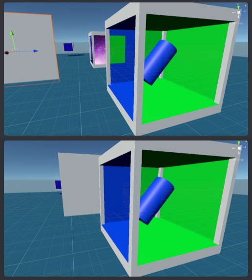
So, I am having some trouble with using a stencil shader in builds for the Quest 3. The intended effect is to reveal an underlying object using stencils. This works in play mode, play mode over Quest Link, and PC builds but does not work in headset android builds. The intended effect looks like the first picture, but in headset the Stencil check just always passes so it looks like the second picture. I have tried changes around settings the depth buffer to 24 bit, making sure depth is enabled in URP settings, changing the graphics API, adding my shader to preloaded shaders, and a bunch of other crap. Pictures of the shader code and the stencil render features are also attached, also most of the relevant settings, not sure what to even try next. Any ideas?


Oh, also this is on Unity 2023.2.3, downgrading to 2022.3.20 did not seem to help.
stancil and depth is enabled? https://docs.unity3d.com/Manual/class-PlayerSettingsAndroid.html#:~:text=Disable Depth and Stencil

hmm, have you tried other android device? I recall that some just... don't support it
in manual GLES you have to explicitly set up GLconfig, enable stencil buffer and set it's size. I guess it shoud be abstracted and handled automatically in some way in Unity but I don't know, maybe it's not?
Hey, i dont know if this the right channel for this but im having some trouble with some shaders i downloaded working in the editor but not in build. I have basically zero experience with this kind of stuff so even getting them to work in the editor was done through a lot of trial and error and i dont even know if i did it correctly. Any help?
also @spark leaf, could this be related? https://docs.unity3d.com/Manual/SL-BlendOp.html#:~:text=Advanced OpenGL blending operations require GLES3.1 AEP%2B%2C GL_KHR_blend_equation_advanced%2C or GL_NV_blend_equation_advanced. They can only be used with standard RGBA blending%3B they are not compatible with separate RGB and alpha blending
Advanced OpenGL blending operations require GLES3.1 AEP+, GL_KHR_blend_equation_advanced, or GL_NV_blend_equation_advanced. They can only be used with standard RGBA blending; they are not compatible with separate RGB and alpha blending.
you don't really use BlendOp, but... who knows
How can I like smooth out a line with noise in shader?
Like I want that cut to be like curved out a bit and act as a mask

You'd rather use smoothstep or an SDF function to start with a smooth line to begin with
Smoothing afterwards is not something you practically want to do with shaders
How? I want to make just the top part of the shader blurry and distorted so you cannot clearly see the basic shape of the object
Somethin like this is what I am seeking

hey! is there a way to put a second material on the same mesh? For example I have a sand material I'd like to put on the ground in this cave, but I can't figure out how it works

thank you ::)
The second to last image is my game view in Unity. And the last image is the game on mobile. Why is my shader not working on mobile? The color and transparency is working, but the Voronoi ripples aren't showing and I don't know why


If you are using an imported model, which you should; you should be able to assign different materials in the submeshes of the object
Where do I see those submeshes? I’ve imported it but it doesn’t seem to have any? Unless I’m lost
It migth have none, did you create the model?
No I imported it
It might have none indeed
Is there a way to create submeshes myself?
use smoothstep offset by sin(u) or something like that
I guess that if you import it on any software specialized in 3D modeling you should easily be able to modify it
Do I have to cut it in 2 lol
Edit the mesh and assign a different material to the faces you want to have a different material in Unity; when importing it back should detect that you have different materials and ask you what material you want on in each material socket
Ohhh I see, I’ll try that, thank you!!
It seems defitnely that the shape I want to cut is that of a sin function, yeah. But I don't know how to move up from there
Mobile just have way less detail, probably has something to do with the quality settings and not the shader itself
assuming uv is the coordinate input, you want the output of smoothstep(v+sin(u), ...other params)
I am sorry but I would be lying if I were to answer that with anything else than "?"

Any idea what settings might be effecting the Shader? Because I've changed any settings I could find that might relate to shader quality or performance and nothing has changed.
Not really, try changing the setting on pc one step at a time to see if you spot it
Nope I give up lmao. I've changed all the settings I can, on PC and mobile, can't figure out why the voronoi noise isn't showing on mobile.
I guess my water is just gonna look like shit
Water is a pretty common mat, you surely can get a free asset somwhere that looks nice on mobile
I don't like doing that because I just get confused. Like just now I imported a URP water mat, and it doesn't work as expected, it'll take me another hour to figure out why, and even then I wont understand wtf the water mat and shader are doing so I can't customize it in the future
I sadly have to learn by doing, I can't just import things and look at them and understand how they work. I have to build it myself to know how it works
Use a vornoi lookup texture
If it’s for mobile that that part isn’t showing up you could just generate a vornoi texture and use that as your vornoi noise in the mobile shader
Hi guys, have a nice day.
I'd like to ask how to get all light source on an object?
I can get the directional light using GetMainLight(), but not Point Light and Spot Light.
Great source: https://github.com/Cyanilux/URP_ShaderGraphCustomLighting/blob/main/CustomLighting.hlsl
GitHub
Some custom lighting functions/sub-graphs for Shader Graph, Universal Render Pipeline - Cyanilux/URP_ShaderGraphCustomLighting
Hey guys, It's me again with more questions regarding my gore system. This time I'm trying to wrap my head around the technique described here: https://download.nvidia.com/developer/SDK/Individual_Samples/DEMOS/Direct3D9/src/HLSL_BloodShader/docs/HLSL_BloodShader.pdf
Now I beleive I found the original code since the download link does not work anymore( found it on the unity forums of all places haha) Here it is: https://pastebin.com/XZAr0R7X
Now obviously this is structured as a multipass shader so I'm wondering how to properly implement it in HDRP. As far as I understand we need to write to a texture and then read from it in the second pass. It is not enterely clear how the "Gravity Pass" writes to a texture, but maybe the magic happens from the FX framework. Ideally I would want to do the gravity calcs in a compute shader and then sample the texture in a regular shadergraph shader. However the gravity pass seems to manipulate the vertex position with this line Out.Pos = float4(2*(In.Tex.x-.5) - pSize, -2*(In.Tex.y -.5) + pSize, 0, 1); I'm not sure what this does exacly except that it puts the vertex in uv space maybe but why do we need that in the first place. Also the paper talks about creating a gravity map, but all the code implementation does is transform a grav vector to tangent space and then add it to the normal map. Maybe it is not worth precomputing it. Anyways I'm looking for input on this from smarter people hah.
Pastebin
Pastebin.com is the number one paste tool since 2002. Pastebin is a website where you can store text online for a set period of time.
Hi so I suck at shadergraph and right now for my outline shader it has to be added as a seperate material which it warns is inefficient and it's better to use multiple passes but how do I implement that
are on URP or HDRP ?
If you have more objects you want to outline, could put it on a specific layer and use a RenderObjects feature on the Universal Renderer to re-render that layer with an override material.
That's a more recommended way to handle something like this - but afaik not really any more efficient (performance-wise). That warning is more for built-in RP. For URP, I'd just ignore it.
Ahh ok, I was doing it for items, so it'd only be rendered for a handful
and it's only for the targeted item, right now I was using a branch to toggle it but is there a more efficient way of doing it?
IT WORKS BUT. My projectiles are in many directions. with this method the projectile is always shown to the camera but with the same face.


Did you try rotating the object ?
yes. this is how it looks now.

I don't think it matters
or maybe i tried with wrong ones. which angle would you suggest?
In my test scene, rotating the object makes the billboard rotate so that the billboard points toward the object Z
Like this.
Or maybe I didn't understand your issue ?

the game is in 3d . the quad is always displayed with the face on camera.
the projectile goes constant toward a direction.
The problem is not that i dont see the projectile. the issue is that If I watch the projectile from some angle I see the projectile wrong


the direction of the projectile is ok just with some camera angle view
Now the rotation of projectile it depends on the view with this shader

I made this shader so the "forward" of the projectile is the up texture axis
So if you change your texture to have a vertical trail, it should be fine
So I converted my project to URP, all the textures were pink (missing), so I selected all my materials and changed them to "Universal Render Pipeline/Simple Lit", and well, they're not pink anymore but the diffuse maps are missing :/

Hey everyone, I need some advice about using a dissolve shader to make an object disappear - I have an object with a material that uses the "URP Lit" shader. It has base, normal, metallic, etc. textures.
I also have a Dissolve shader that I'm trying to use to make that object dissolve away. It looks a bit like this:
The issue here is that I want the black part of the object to be invisible, but I can't find any tutorials on achieving something like this.

I made a brand new HDRP project with the default preset for it, and it was all missing textures so everything was pink, so I clicked reimport all, and now the scene is just completely missing lol

You need to create a shader graph that has cutoff transparency enabled. Then you need to add your dissolve mask generation algorithm. This algorithm will produce a mask value between 0 and 1. You plug that mask value into Alpha on the master node and it's done.
Thanks for the help. So this is what I have currently. The issue is that I'm very new to shadergraph so wrapping my head around this is... Slow going.
I know I currently have this noise generation which is determining the shape of the dissolve and it's calculated on the Y axis, it's calculating an offset for the edge glow, etc., but the difficulty I'm having now is, either:
Figuring out how I can apply a series of textures to the shader itself (ideally programmatically, taking them from the base material at runtime before swapping the material with this shader), OR
Applying this shader additively to an existing object so that it doesn't render portions of the material underneath.
Can you offer any advice just glancing briefly at my graph? Also I completely understand that at this point I probably don't know what I don't know, and so might not be asking the right questions - Any advice (and patience) you can offer would be really greatly appreciated.

@tiny sphinx the only practical way is to make your dissolve a subgraph and add it to every shader graph that's used with dissolvable objects.
A subgraph... I shall look into that. Thank you so much for pointing me in (hopefully!) the direction I need to go in! 🙏
Hey! I'm trying to apply a texture to a tree but nothing's going right. The tree is supposed to look like the first pic, but ends up like the second... The texture is the third pic, but it changes when put inside unity and screws up the tree. Is there anything i'm doing wrong? I've been stuck with this for days


thank you 🙂
Interresting stuff
Is pipeline converter available on Unity 2019?
I don't see it under window > rendering
nvm it's under edit > render pipeline > universal render pipeline
all my textures are still pink though.....The base color is still selected properly on all the pink textures so they're configured properly, just not showing up :/

You can draw custom stuff at the injection point you need using custom pass API, and HDRP custom Renderer Shader template(single pass shader pick the name/tag as you want ), then in the custom pass you will have handle the result filter of the DrawRenderers using shaderTagIds to call only your custom renderers shader pass to be drawn, so you can create ScreenSpace buffer by create RTAlloc for few RenderTexture from your Asset folder and Draw function using the shaderTagIds that is the tag of your HDRP Custom Renderers shader, in the end you can writte pretty much everything that you need but that is not directly draw this way, I guess Nvidia just store the screen space result of the FX, then the gravity like a fullscreen (i guess)
how can I rotate normals after billboarding it in vertex shader? I grabbed some shader code for it and it works fine (but I need to somehow limit rotations only in Y axis, but its another problem), but my shadows is not rotating with object and by googling I found that I need to rotate normals too, but I not get a clue how to even do it
even basic stuff is by a miles away from understanding for me
Billboard often use worldspace normal that is "Y up" to have uniform shading, so you can literally rotate the worldspace normal vector in the shader (like grass), but it will have nothing to do with your shadow issue
Hello! Remy helped me out a few weeks ago making a custom function for Alpha Cutout while tracking objects. Its been working great but I just caught an issue I hadn't even considered.
When my object rotates the cutout square does not rotate. Obviously this isn't an issue with circles - but if I pass in the objects rotation how can I apply it to the square to replicate the object?
{
    float3 _UVPos = 0;
    float _radius = 0;
    bool _isSquare = 0;
    float2 uv = float2(0, 0);

    mask = 0;


    [unroll]
    for (int i = 0; i < 32; i++)
    {
        _UVPos = _Worldpositions[i].xyz;
        _radius = _Worldpositions[i].w;
        _isSquare = _isSquared[i] > 0.5;

        uv = (_UVPos - worldPos).xz;

        if (_isSquare)
        {
            float2 d = abs(uv) - float2(_radius, _radius);
            d = 1 - d / fwidth(d);
            mask = max(saturate(min(d.x, d.y)), mask);
        }
        else
        {
            float d = length(uv / float2(_radius, _radius));
            mask = max(saturate((1 - d) / fwidth(d)), mask);
        }
    }
}```you want to rotate the square? is it absolutelly usefull?
you square come from world UV space, I guess you can rotate the UV before float2 d = abs(uv) - float2(_radius, _radius);
you will have to tranform the WSpos to object/mask pos center (or inject object/mask pos too) , rotate the UV using a new Vector3 "rotation", then object to worldspace to reapply your modified worldspace UV, so rotation would stay centered to the object/mask
Make sure alpha is enabled in texture import settings. Also enable cutoff transparency on your material.
Alright time for new outline obsession.

Gave myself 1 day to recreate this amazing artwork - The tent and small props are assets I made for another game
The linework here is seriously impressive. I looked into Sable recently so I'm aware this is likely achieved through some Sobel edge detection post processing shader.
The really impressive part, that I'm unsure as to how to replicate, is the linework WITHIN the models.
For detailing within models, Sable used these specialized textures that defined edges.

But I imagine drawing a non-contiguous line such as these...

would be quite hard with this technique
Would you happen to have any idea as to how this was achieved? Do you think those internal outlines are just regular textures? They sooort of seem to shrink as the camera moves back?
There are endless ways to achieve things. There could be mask maps that break up the edges, there could be extra meshes, there could be triplanar masking 🤷
Alright fair. Uuuh how would YOU do it?
I would try all sorts of techniques and apply whatever worked best for the workflows required to build each piece of the environment
Ok let me try a more specific question then. Looking at the hand dawn textures in Sable, you can see that if I were to draw a single line, Sobel edge detection would draw two edges. One for each side of the line. Is there some technique or algorithm that could give me just 1 line?
Cause I’m thinking maybe I could just make one big “outline mask” from multiple sources.
Edges, depth and drawn lines.
And then just slap that over the whole image.

Ok yes BUT this breaks down pretty quickly when you want to make it non-contiguous 😛
- this as a mask.

What about full on spritework like this?

I don't understand the question. The lines are the transition between white and black, and the cuts in the lines are black in the mask texture
add another channel for line thickness if you wanna get wild
Ok wait no I think I’m seeing it.
This could be one weird ass pipeline though.
Lot of textures just to define edge boundaries.
That's what happens when you have a specific art style
True true
Note that you would cram it into as few textures as you can
Oh and just use different channels?
Yes
Iiiinteresting
legend. thank you so much

So how would I feed in these "fake edges" into the edge detection post processing shader?
Have the material write them to a render texture or something?
Sure. Here's a thread by someone I know who goes over their pipeline https://www.reddit.com/r/Unity3D/comments/taq2ou/improving_edge_detection_in_my_game_mars_first/
Thanks I'll give it a read.
@warm moss Hi! Thanks again for your help 🫡 So I didn't end up using a subgraph, instead I've opted to add texture properties to the shader material that it copies from whatever it replaces, so with a little switcheroo in code I get the best of both worlds. Figured you might like to see an update and I wanted to thank you again 😇

Storing colors as an index to a predefined color palette in one of the channels is some raw fucking shit.
Defining surface IDs is a very cool way to handle this.

I would assume though that you'd have issues where objects that overlap and have identical surface IDs would struggle to identify edges.
But you have normal detection AND depth detection to fall back on.
In that case I guess I can just use a similar strategy for textures and sprites.
Just have a texture with effectively random colors that defines where the line needs to be, and a mask texture to remove unwanted lines.
Very cool.
Thank you, I'll check it out.
Beside, what is the structure of struct InputData? Where can I find more information about Unity's shader API like that?
Hi all, I'm an absolute shader noob.
I've been using this asset to add outlines to my game.
https://assetstore.unity.com/packages/tools/particles-effects/quick-outline-115488#reviews
But, my game uses an ismoetric, orthographic camera - and the strength of the outline appears to be affected by where the subject is positioned in the orthographic viewport.
I'm guessing somewhere in the shader its setting the size of the outline relative to the camera position - OR my orthographic camera is not correctly configured.
Any ideas?


Use the Quick Outline tool for your next project. Find this and more particle & effect tools on the Unity Asset Store.
I'm guessing i will need to write my own outline shader...
Unity URP and shader graph files are visible and even on github
Nothing is documented :D
Thanks for replying!
I did have a little research by reading hlsl files in URP library but couldn't find the definition of InputData and SurfaceData. Plus, My VS and VScode doesn't have shader intellisense so I can't track them down.
I'm now quite confused about my own question. Maybe it is too dumb/simple or lacking information or something. And no one seem to care about my question posted on the forum (there are posts after my question 30 mins and they even reach 10k views). It'd be great if you could give me some feedback!
I have just taken it as a 'it needs to be there to work'
It might be in the srp core package tho
Hello! I've made this wind shader using CodeMonkey's video and it shows live in the preview inside the shader graph editor, but in the scene view it only updates when hovering over it or (at least for me) just at random. (Ping with replies pls)

There's an option to update every frame in scene view; by default it's off.
Around the gizmos tab iirc?
Found it! Thanks.

Hi. I had a misunderstanding: They say on the Internet that you need to check the box next to Enable GPU Instancing so that there is less Batching. For some reason, it works the other way around for me. What's wrong?


Hi there,
Im noob to shaders, I'd appreciate if you could guide me how to create a Canvas Shader that procedurally generate skelteon-text effect
Appreciate
https://mui.com/material-ui/react-skeleton/
https://ionicframework.com/docs/api/skeleton-text
Display a placeholder preview of your content before the data gets loaded to reduce load-time frustration.

Ionic Framework Docs
ion-skeleton-text: Skeleton Loading Placeholder for Text

Hello, I got a problem with a custom shader that I want to make that makes my player look like this. My custom shader graph currently looks like this and the sprite sheet is tiled correctly. Any help is appreciated.


Connect the A output of the texture sample to the Alpha port in the master stack
Thanks @regal stag😊 . I wanted to make an outline to the character and didn't know why I didn't display correctly at first.
Did you follow a specific tutorial that neglected to mention the alpha step? I'm a bit curious why this issue comes up multiple times a week
did you already disable the static batching for the game object?
disable static batching == there's no mesh combine
check via frame debugger
hi all, I have a part of a shader that is creating a mask for waves of foam for a beach. I'd love to make this wave wiggle around based on the world position such that rather than a straight-ish line, the line makes a big sine wave kind of shape. Anyone have a good starting position for this kind of thing? I feel like it involves multiplying time and getting it on some sort of sine wave, right?

if you use greater than to make a line, then assuming that this line is in x axis, before greater than add sine(y+time)
Hi! Im writing an SRP and I want to do some compute. In SRP, all my textures are int TextureIds because thats what the API wants
like
cameraCmdBuffer.GetTemporaryRT(nativeScaledCameraColorTextureId, resolvedTextureDesc, FilterMode.Bilinear);
but all the compute commands want actual real textures like Texture2D and RenderTexture - how is this handled usually?
Oh, I just spotted SetTextureFromGlobal
okay, question retracted 😄

https://www.youtube.com/watch?v=gRq-IdShxpU&t=96s&ab_channel=Unity
I'm following this tutorial, and I've done exactly what he's doing up until 2:32, but my plane doesn't have a gradient like his :/


In this video, we'll take a look at how we can use the Shader Graph feature in Universal Render Pipeline, or URP for short, with Unity to create a water shader! The water shader can be simple or complex, and include the features you desire. Let your imagination get wild in this tutorial, or simply follow step-by-step to get about the same result...
I'm running Unity 2019.4.39f1
ah wait nvm, didn't click save -_-


Alright different issue, 6min mark in the vid....my water now enduces seizures in those with epilepsy...
**FLASH WARNING
Hey, how to convert depthmap in object space from an object to world position?
Suppose we have a depthmap grayscale image for an object?
I am writing my own unity shader with fragment + vertex, and I don't know and can't find how to apply lights if the only thing I have in my shader is writing depth, normal and basic material properties like albedo, specular etc.
assuming the output color is color, I tried color.rgb += ShadeSH9(half4(myNormal, 1));, but it seems to be unaffected by the ambient light color
Built in pipeline btw, and I currently wrote only ForwardBase
do I have to use surafce shaders to make it work with default unity material system???
after that?
multiply it with unity_ObjectToWorld?
Or if using shadergraph there should be a transform node or something
Did you try a bit to search by yourself how light calculation work ? There's plenty of material for this, and there is plenty of ways to achieve lighting
im in search of performant way , as it's only a matter of single realtime spot light affecting on lightmapped object
The most performant and less mathematically expensive is lambert shading.
But that works for non shiny surfaces. Else you'll need phong.
You can take inspiration from the rendering tutorials here : https://catlikecoding.com/unity/tutorials/rendering/part-5/
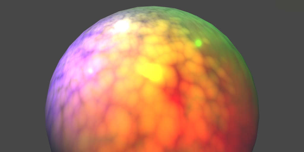
A Unity Rendering tutorial series about supporting multiple lights. Part 5 of 20.
thank you , Im already folllowing that one
is this tutorial relevant today, or is it obsolete (published 2016)? I recall a lot of shading stuff being dynamically changing and quite infamously not well documented
2016 is when unity was on version 5.x
iirc it is still valid if you use BiRP.
I was referencing it mostly for the lighing calculation part, but even here some of it is "obfuscated" by unity macros
btw, with the upcoming Block shaders, will the reliance on macros be smaller?
for example in favor of functions and whatnot
I don't think so 😅
But I'm not sure, sadly I haven't spend a lot of time trying block shaders myself
damn :(
Hi guys,
I need to make a shield with local distortion shock wave shader in the point where a bullet hits it. is it possible? any idea?
the shield it should be a sphere. when the projectile hits that, it should make a wave distortion effect in that local point, the shock wave should be spread through the whole sphere gradually..
should i use a vertex shader, a fragment and vertex mixed or should I use a vfx graph?
I would use particles in the shape of a partial sphere, with the shader animated through vertex streams, rather than trying to make a shader with multiple animated shockwaves if it can be avoided
what went wrong with my shader that made the preview pink?

I thought the same but it does not look good.
I already made the effect but I would like to to apply it to the shader i just need to localize the point of the hitting vertex and make the wave from it
maybe with a shader graph i could have more control of that
this is the shockwave

"Apply it" to a shader? Does not look "good"?
It's somewhat unclear what the issue and goal here are
what is this weird black color when I apply it to my sprite and not when I apply it to a 3d shape?

im a shader graph noob plz help
heres the shader if it helps

nvm the issue is suddenly gone
why do these errors keep come and go
Sorry I try to be more clear: this is my effect.
Now the wave start from z axis and it spread in this direction.
I would like this wave effect came from a bullet impact so in this case the z axis should be always faced toward the bullet. The problem is that bullets come from all directions.
That's why I've talked about "local" point. Because now the point where the wave start is fixed.
It would be cool to make a fragment/vertex or both shader that has this wave starting from the impact of a bullet.
Now is looped but I would like to see the wave after the collision. Should i turn the sphere every time? is there a way to make it "understand" where the collision comes and use that point as starting point of the wave?
Heya all, I'm a little confused on how to implement more obscure maps into my shader. For example I'm trying to implement a detail map but I'm quite confused as to how. From what I can see, each channel represents a set of information.
Please correct me if I'm wrong but I belive these to be:
R: Detail albedo
G: Detail normal
B: Detail smoothness
A: ???
I assume I take these channels and blend them with the other relavent nodes?
Did you read this? https://docs.unity3d.com/Manual/StandardShaderMaterialParameterDetail.html
These are another set of textures, similar to the primary ones for albedo and normals, with a mask to decide if they're applied or not. Also check the standard shader source code from the repository:
https://docs.unity3d.com/Manual/StandardShaderMakeYourOwn.html
This is a bit old, but https://www.youtube.com/watch?v=DGGZFLSHYUw
Here's one using a texture array with a map as an index into the detail array. https://www.youtube.com/watch?v=avZ26yW2KBw
✔️ Works in 2020.1 ➕ 2020.2 ➕ 2020.3 🩹 Fixes for 2020.2 and .3:
► When you create a shader graph, set the material setting in the graph inspector to "Lit"
► The "albedo" field of the master node has been changed to "base color"
► Editing properties must be done in the graph inspector instead of the blackboard
If you have terrain or a large buil...

In this shader tutorial, I show a more advanced detail mapping technique that allows you to apply multiple detail textures (even 16 or more!) to your mesh using only one texture sample. This method can be used when you're applying detail to a character with multiple types of materials that each need need their own detail.
Here's last week's vid...
What is the best way to make textures in unity?
Also is there a way to import the textures from blender to unity when importing the fbx?
You could use a rendertexture to 'contain' all the incoming waves, and if you are using raytrace to check for bullet impact, you can use raycasthit.texcoord to determine where to draw the wave on the rendertexture
not sure if this has something to do with shader (more like #🔀┃art-asset-workflow )
but usually textures are made using external image editor and imported to unity.
thank you very much . could you show an example to show me a way to chack the impact and show the wave from that point? bullets are meshes.
I see
you should think about decals that can create your wave as normal
is this normal or did i screw something up?

or is that compiling Every shader in the project, even though i only selected to compile one?
I made this shader for something in my game but i need it to not stretch/compress the image i want it to just show a smaller portion


You're currently using UVs to determine the look of the image. UVs are always constant for vertices (e.g. in a quad the top-right vertex would have position (1, 1)), which is why it stretches. If you want the image to be independent of vertices, then you can base it on something else, like screen position, world position, or object position.

how can i change the material of a pre-made shader i didnt make?

Hello math fellas, I want to create a sphere that uses angle calculation, so like longitude and latitude, but the best I could do yet is an iterative process, which makes it kinda bad for a mapping does someone have a better idea?
I wrote this mapping and it's awesome, but sadly it's iterative so I can't really use it, does someone know a mapping that can achieve a simmilar effect of reducing the latitude change close to the poles?
void main()
{
    uint px = vertexID % resolution;
    uint py = vertexID / resolution;

    float x = float(px) / float(resolution - 1);
    float y = float(py) / float(resolution - 1);

    float longitude = x * 2.0 * 3.1415926535897932384626433832795;

    float radius = 1000.0;

    float pi_interval = 3.141592/float(resolution-1);

    float latitude = 1;

    for(int i = 0;i<py;i++){
        latitude -= asin(sin(latitude)*6.28/float(resolution-1));
    }


    float px_world = radius * sin(latitude) * cos(longitude);
    float py_world = radius * sin(latitude) * sin(longitude);
    float pz_world = radius * cos(latitude);
just create another new material
hi does anyone know why my shader has gaps from some angles, but is ok from others?


not sure if this would be possible with a shader, but i have a 3d model that uses two materials: one for the rock walls and one for the ground, and I just assign the materials in unity after exporting from blender. This is what it looks like, and I was curious if there would be a way to smooth out this material change between faces, or have the face fade to black when its connected to a material that is not the same.
Using URP

you can use blendmap I think
interesting, do you have a link for info about that?
Unforunately no, but the setup is basically like this.
Then you just sample both rock and ground texture then interpolate using that blendmap
||I used this technique to cut drawcall by more than half||

Something like this
https://docs.unity3d.com/ScriptReference/RaycastHit-textureCoord.html
But instead of using texture2d setpixel and apply (which can be really slow), you can use graphics blit (which should be faster)
you might need to do the blits every frame with increasing scale and decreasing alpha to make the 'rippling' effect
🤔 you also might need to handle if the ripple is on the edge of the render texture
Whats the best way of returning "results" from a compute shader?
I basically do a bunch of computation off a texture, and get some number of results way smaller than the texture size, think "points of interest" in the texture
I don't really want to pass back and forth a buffer thats 1:1 size of the texture but I don't see any other option?
I see theres an AppendBuffer but i'm not sure how that works
And I get that theres "GetData" but the problem I have is how can I conditionally set this so I only have results I need/want
Or am I always going to have some redundant results in this case
Perhaps this is what you require https://docs.unity3d.com/ScriptReference/Rendering.AsyncGPUReadback.RequestIntoNativeSlice.html
Unity 2023.3.20
Trying to pass in the _CarmeraDepthTexture to a custom function in shader graph. Get this error:
redefinition of '_CameraDepthTexture'
Did not have the same issue for the _CameraOpaqueTexture.
Depth texture and Opaque texture are both enabled in settings.
I am not sure how to fix this, I need access to the depth texture in the Custom Function. Any others ways to get it in there or fixes for this problem? I am very new to HLSL.


Also, I need to sample multiple pixels so just using the built in depth node on Shader Graph doesn't work as I can't get a section of texture all at once.
This is because for ... * reasons* the graph already defines the camera depth.
You can take example on how it is done in the URP implementation of the sample depth node :
And you can even directly use the same macro :
SHADERGRAPH_SAMPLE_SCENE_DEPTH(uv)
Seems to work, I love "reasons". How bad the documentation is for shader stuff compared to everything else in Unity is making me pull my hair out.
Thanks for the pointer.
To be fair any documentation for shaders is bad.😬
Or rather, unclear and hard to understand
I know my explanation isn't great 😅
It isn't easy to track what conditions and settings make shadergraph declare that texture or not, so the easiest way is to use the macro that handles the boilerplate for you.
I accidentally made an edge highlight shader, this is not what I wanted.

hey! how do get the edges of these cells

You don't, distance to point can't be converted to distance to edge
You need a different (or modified) voronoi algorithm that gives you distance to edge information
aw man
I have to use hlsh for this one yes?
or can I write a custom vornoi in the shader graph?
(Im new to shadergraph)
You can use Step to get the white areas only, though. If that's what you need
Actually it might not be consistent
Yeah, can be done with custom function node. I have some examples on an old site here - https://cyangamedev.wordpress.com/2019/07/16/voronoi/
Color bleeding past edges, still needs lots of fine tuning but progress is being made.

Hey 👋
Have you guys got any pointers or resources for creating stylized vfx in the style of Spellbreak / Overwatch??
https://www.youtube.com/watch?v=0g2ysh1Hzek
like this effect for fire example?
Thank you!

Testing out the Fire Gauntlet in combination with the Stone Gauntlet in Practice Mode
I have a problem with the texture on the modelhttps://cdn.discordapp.com/attachments/900380950083534888/1211681472382107648/image.png?ex=65ef154e&is=65dca04e&hm=7215439e8127362f825528bcb4b14a04c97bdaf9786cc7014dc6a3e87a9de07a&

Bad UVs ? Wrong tiling mode on the texture ?
Probably not a shader issue
Helloo
Heya so I wanted to use a temperature map in my shader to change the color of grass, pretty simple yeah. Only problem is I want the same value to be accessible from scripts. Now I could pass the values into the shader but that could take up a lot of bandwidth per chunk so it's not really that feasible, plus I'm not even sure if passing the values per vertex in would even make it look good seeing as the fragment shader would be determining the color. Anyone got any ideas? I'm almost considering yoinking the noise code from the shader and just re-creating it in my script
Quick shader graph question, but if I have an RGB mask where all 3 channels require different UV offsets, that means I have to sample it 3 different times, correct?
Correct
Is there a way to select only transparent pixels in my texture, or ignore opaque pixels (via shadergraph). I've got transparent colors that are acting as shadows and need to be affected differently from my opaque colors.
I've done the opposite by using a step node to ignore the transparent colors, but now i need to select only them.
One minus before or after the step should work
I have 3 tower prefabs. I am trying to make a simple shader graph for transparency for these. Am I going to need 3 seperate shaders as each tower prefab has a different base material?
Or can I create a single shader and somehow apply it to 3 different materials?
Messing around with it now but confused
!collab

📢 Collaborating and Job Posting
We do not accept job or collab posts on discord.
Please use the forums:
• Commercial Job Seeking
• Commercial Job Offering
• Non Commercial Collaboration
A material does nothing more than contain a set of values for use by a specific shader, so "applying a shader to a material" doesn't really make sense
Such a property can be a texture reference, so that multiple meshes can use the same shader with different textures
by apply i meant select in the dropdown box but yes ty
Materials are always created for a specific shader
If you want multiple meshes to use the same shader, assign a material (or several different materials if you wish) to them that use that shader
If you need to swap the shader used by a mesh at runtime, you would swap the material
Got it, thanks


Hello, I've got this shader up and running that works like a jigsaw puzzle between 2 colors using a clamped noise pattern and a 1-minus version.
My next attempt at upgrading this shader is to see if i can provide a more natural border between the two colors. Preferably something like this:

I can provide the sprite pattern that would be required for the edge but i'm not sure how to implement it such that the two colors would intertwine.
Hi, how can I change the material that is set on the full screen shadergraph by code? I mean the "blit" material that is set on the URP.
anyone got a gouraud shader
maybe you could just set pixel light count to 0, thus, forcing everything to be vertex lighted
ok
Do I need to include URP's Lighting.hlsl in my custom function to use the method TransformWorldToShadowCoord()?
Having some difficulty with this
If I don't include it, I get the error
undeclared identifier 'TransformWorldToShadowCoord' at line 10
But if I do include it, I get this error
_AdditionalLightsPosition: implicit arry missing initial value at line 151
Yo does anyone know how to make a simple custom text shader using shader graphs? Since normal text shaders just don’t work on quest 3
I’m using unity 2020.3.44 btw
wasn't sure where else to put this but anyone know why when i export fbx into unity it turns out like this?

Anyone?
what is this?

a reroute node, its for organisation
can i find it in unity? This image was from a video.
just double click on a node in the graph and it should spawn one
Double click on a line that connects nodes
Hello everyone, is there such a thing as a grayscale shader? Like if the shader is over anything it turns that into black and white?
or maybe that's a global volume?
I can't find the channel
Is there any way to avoid these artifacts that happens whenever two of my sprites are at the exact same Z value?
https://gyazo.com/2a427c814c79e70c81d8c132ca30bfcc

This is the shader I'm using

How do I make my emmision so it glows
Because just checking the emmision box under a standard shader does not make it glow
How would I make a script where the UV of any white colored vertex color gets controlled by the movement of a bone
Emission doesn't glow by itself. It just ignores lighting.
Does anyone happen to have a version of the standard shader with two detail maps?
I tried editing it myself, and while I have no errors, the added texture slots don't appear in the inspector. I have no clue what I'm doing
Show your code
You want post processing bloom, it's not related to shaders
Hi everyone!
I'm trying to create a sort of a force-field like material that glows when in contact with other objects in the game sort of like this?

I've seen a lot of tutorials on how to do this, but it seems they all use URP, and my project is using the built-in render pipeline
I thought it was impossible to do in the buit-in, but then i found this water asset that runs in the built-in pipeline and achieves this effect

I'm a noob at all this shader stuff. Can anyone help me figure out how this works? I have the water's shader code but I don't understand how any of it works
you'll need to get depth buffer first, maybe from camera depth buffer, then pass it to the shader.
https://docs.unity3d.com/Manual/SL-CameraDepthTexture.html
In the shader, you'll need to subtract the depth buffer with current texel z depth, that will give the rough information for where the effect should appear.
https://www.h3dlearn.com/blog/shader-graph-intersection Also, this is a good general overview of how the effect works if you want to understand that before trying to recreate it
Hey I figured it out! Thanks @haughty mesa and @tacit parcel

So I am quite new to shaders but i'm trying to figure out how to make this mechanic happen. The idea is that i have 1 long model but i use a 'viewing box' to clip away all the parts of the model that isn't inside of the viewing box. This part works wonderfully. The only issue with it is that the cutoff is quite abrupt (not visually pleasing) and when cutting of the model it shows off the insides of the model. I wanted to try and use an intersection shader to try and cover up those sides. Another option would be that the clipping is more a fade than a hard cutoff, but either way i don't know why the shader doesn't fully work nor why these two shaders have a weird interaction together. Does anyone know how to help me here?


Are there any wave/nodes I'm not aware of to get pingpong time in shader graph? Sine and remap work ok but it seems like it hangs near the extremes of 1 and -1 for while instead of smoothly interpolating back and forth.
oh huh I thought I tried that one but yeah works great ty
Heya, trying to remove tiling here but despite my efforts it is not getting any better. Anyone know why?

It's overlaying fine but even with primes its just not great at all
What does "remove tiling" mean here, that the texture you are using appears too repetitive?
yea mb
There is no any one calculation that can beat repetition that works for every texture and every viewing angle equally, rather there are many varieties
It'd be better to show the issue itself
And usually the best thing you can do is change the texture itself to have less distinctive patterns
Isnt there stochastic plugin around? Maybe you could try that instead
Unity has an old procedural stochastic texturing node on git
But that method is also situational as it doesn't work for textures that aren't stochastic themselves
Hi everyone! I've seen a shader made in UE5 that use a "DistanceToNearestSurface" node to create a mask around the intersection area of 2 meshs in order to blen 2 different materials using this mask. There's a way to recreate this in Unity with the shader graph?
Technically possible but it's not a simple effect
In Unreal it requires enabling generation of signed distance field representations for each mesh
Unity has a tool for that included with VFX Graph but it's not a box you can check per mesh
After that you need to have a system that allows the shader to sample the SDFs around it and then do the distance math
Thanks, it sound absolutely not simple 😅
Sorry for a dumb question... but if I generate a mesh with hlsl, can it be a collider?
hello guys, I am using a render texture to display my UI with post processing effects, what I am doing is to use a black mask in the background to discard/make transparent that pixels only leaving the UI. The thing is that I am getting a weird outiline and I cant use the black color xd. Idk what other solution I could make.
this is the result

How I can Isolate the UI in this render texture?
I simply copied the standard shader code from the github and copied the 3 detail related parameters, pasted them and renamed the variables. I couldn't see any other references to them in the shader code, but again, I have very minimal understanding of shader code.
Well if you are not seeing the parameters at all its either the shader is not compiling or it is still using its custom inspector that is not showing your custom variables
how to access color from sprite renderer in a shader graph?

I'd try either adding a parameter called "_Color" or trying to sample vertex color based on the built in sprite shader.

GitHub
Unity Built in Shaders. Contribute to TwoTailsGames/Unity-Built-in-Shaders development by creating an account on GitHub.
GitHub
Unity Built in Shaders. Contribute to TwoTailsGames/Unity-Built-in-Shaders development by creating an account on GitHub.
it looks like its pulling from a combination of the two.
I tried both and it didn't work
agh
also tried _BaseColor

did that work ?
no, it keeps the local color instead of referencing from the renderer
dang : (
gonna need to poke around some more w/ urp specific code brb

interestingly in URP its the same setup
I was expecting to find some material property block here, instancing something or other
vertex color * _Color * _RendererColor
one of those is it -- it's possible its not getting set for some reason though?
do you have those variables publicly exposed ?
they are exposed
I tried with all the three
I did a simple experiment here, just linking the color to the output, nothing else in the shader
like this

neither of them output the color in the renderer
using 2023.1.9f1
oh! I was sending notes from 2022.3.7f1
that could be part of it
I dont know the answer to this one! But I think looking at the shader source for materials that do work is the way to go.
Unless it just won't bind with shadergraph.
In which case you could try copying one of the built in shaders
and tinkering with that instead.
thanks anyway.
I will check the urp folder and find the default shader
` Properties
{
_MainTex("Diffuse", 2D) = "white" {}
_MaskTex("Mask", 2D) = "white" {}
_NormalMap("Normal Map", 2D) = "bump" {}
    // Legacy properties. They're here so that materials using this shader can gracefully fallback to the legacy sprite shader.
    [HideInInspector] _Color("Tint", Color) = (1,1,1,1)
    [HideInInspector] _RendererColor("RendererColor", Color) = (1,1,1,1)
    [HideInInspector] _AlphaTex("External Alpha", 2D) = "white" {}
    [HideInInspector] _EnableExternalAlpha("Enable External Alpha", Float) = 0
}`
Apparently, those properties are legacy, they don't serve a purpose at the moment
even using the sprite-lit-default, it doesn't get color from sprite renderer
same for sprite-unlit-default
I assume they changed something, and it is not used anymore
Not sure is this should go to UI/UX or shader
Is there a way to overlay an image on top of 9-slice image on UI?
Using mask usually result with jagged edge, so I tried overlaying with shader
Using texcoord wont work because it's 9 sliced, so I try using worldPos instead and try to offset it with object position, but it seems that I cant even get the image transform position properly (using mul(unity_ObjectToWorldPos, float4(0,0,0,1);), seems like it returns the canvas position instead of the image position (and that's the easy part, I still have to get the image size or bounds)
So is there something I can use to properly map the image overlay?
I'm having issues with Shader Graph. I have two detail maps, but if I leave either one as none for the texture it makes the shader come out almost black
I have the two detail maps going into a multiply node, then that node going into a multiply with the base texture. Would adding a white base color to the detail maps solve this?
you might have found the answer, but yes
is it possible to parametrize these?

that said, I think alpha blending might offer more flexibility in the future
specifically, I want to be able to change "render face" option per instance of shader. I could always create a duplicate but this would be cleaner
So I tried that and now the texture is just always black 😦
What did you mean by alpha blending?
I'm new to shader graph
Allow Material Override will make most of those options appear in the editor
much like how Unity's lit/unlit shader exposes them
Did I do something wrong here? With the way this is, if I leave either detail texture as none, the material turns black? Any fix?

All I want to do is basically recreate the standard shader but with a second detail map, and the ability to scale the detail normals seperately. I still want it to use the alpha of the albedo for glossiness and everything else be the same. But I also can't figure out how to use the alpha as a specular mask in shader graph either
Hi I am facing a weird issue,
I am making a 2D shader using shader graph for my ui components. It works fine in edit mode.
But when I enter to playmode, it's giving me a square.
In edit mode

In play mode

How can I fix this?
@cursive jewel my guesses would be one or more of:
- somehow material is not applied
you can probably test this by writing say RGBA(1,0,0,1) to the fragment output - if its a red square the material is working - something weird may be happening with zwriting on transparent pixels
I'm not familiar enough with shader graph to have any good suggestions here, but perhaps moving some other objects around to test - something specific to using shaders with UI elements
I've seen some pretty wierd behaviors, it might be worth outputting the UV coords as float4(uv, 0, 1) to make sure your getting sane inputs, but I'm not great with unity UI stuff
why do I see some Shader graph examples where the nodes have these colored bars at the top?

How do I get the cool colored bars?
And what do they mean?
Ooo
On another note, I've got a question. I have a scene here with 2D sprite characters moving in a 3D world. Been working on solving some of the visual problems that came with that.
Currently I'm trying to figure out a good solution for shadows.
As the characters become perpendicular to to light source, the shadows shrink down to nothing.
This makes sense given that they are flat planes, but obviously it looks a bit... odd.
I'm not sure how best to solve this.
Even if I could somehow rotate the shadow along the light direction vector, I still think that would look odd.
Maybe I should just have a single directional light as the only shadow source?
Single directional lights work, but if you do want some point lights then it becomes a bit more complicated. I was thinking of some solutions like vectorizing the images and loading them into blender to give them some depth then rendering them for shadows only.
Like, even if you were to get back the shadow map data of all the sprites pointed towards each light source, the proportions wouldn't look that great. No clue how a lot of these games do it but I'd expect there's a lot more math involved.
and I guess another problem is that you'd have a different sprite depending on where the light source hits the characters which you'd have to take into account, but there are games that just will just use the sprite in use.
I did try this way and honestly wasn't that bad, but the project had hundreds of enemies so it just wasn't doable for my requirements.
I've seen some games do it where they rotate the shadow to be parallel with the light source, and then also have a sorta circular shadow "smudge" at the bottom of the character's feet.
So the odd rotation gets obscured.
@ebon basin

Here's an example.
Enigma of Fear: https://www.youtube.com/watch?v=9t2PRRnE8vo&ab_channel=Unity
It's a cool solution, but would kind of only work with very "thin" characters.
smudge is good to fix the peter panning issues
the what
that's what they call it lol
who calls it that >_>

Stack Overflow
I'm adding shadows to a scene in OpenGL by doing two draw passes, one to a depth map and one to the normal frame buffer.
Without using a bias when using the depth map, there is a lot of shadow acn...
oh hey, my mate posted that question
lmao

yeah, that's how I've had it.
It's a shame but I might just need to let go of shadows for the entities.
They need a proper drop shadow anyway.
Since the player needs to gauge where they are when in the air.
recently I just been watching a lot of 3D to 2D videos and it got me more interested in doing this workflow backwards
3D models but with the illusion of 2D
deadcells is an example
easier to animate, easier to do the shadows, easier to work with unity's 3D engine
Hey, I'm making my own custom sprite shader in shader graph with some extra effects but would like to keep the normalmap functionality as it exists in the default sprite-lit material
Ah I see. Personally I've really become enamoured with the 2D sprites in 3D world style that's been getting more popular.
How do I get the normals to be correct based on the _NormalMap secondary texture?
the depth idea I had above is legit though even if you were to stick to 2D sprites, but that's something that requires more assets to do
I can access the normalmap through _NormalMap, right? But just sampling that and sending it to the tangent space doesn't appear to work.
I'll try a simple decal shadow. We'll see what happens 😛
Ah, I couldn't just use "sample texture" I should have used "Normal from texture"
There's a node to extract the normals if that's what you're asking
oh wait you found it
It's not producing the same as the normal sprite shader though, more jagged
I should consider using the shader graph for sprite stuff more. HLSL is a pain with srp and sprites
Apparently I should not be using the "Normal from texture". This makes a normal map based on a texture and is not suitable when I already have a normal map I want to use
Still, just applying the normal map to "Normal (tangent space)" does not produce a good effect
Light only applies from the bottom-left angle
Essentially implying everything is heavily facing down-left
that's because it's using ddx and ddy which samples every 2 pixels
if you are using _NormalMap, you need to unpack it using unpack normal
Ah, unpacking it appears to help
Thanks for this
The reason normal from texture wasn't working was that instead of a heightmap I was feeding it my already made normal map
So it was trying to recreate a normal map based on a normal map
How does one set a texture to use the albedo alpha as Gloss in shader graph, like in the standard shader?
there was one problem I never got around but urp decals I couldn't limit the intensity of color of overlapping shadows
and I think you'd have to do that in a shader yourself
Knowing computer graphics, there's a janky solution for that.
From 1994
I imagine there must be someway to write to the shadowmap
or whatever is powering shadows
@ebon basin How does this look?
honestly looks fine. I'd deal with shadows later anyway if it's a problem
True. The only reason I'm kinda trying to establish the look early is I'm unfamiliar with such a specialized workflow (2D sprites 3D world).
Want to make sure I can actually... do this >_>
@ebon basin Actually, be real with me for a second? Does this style look good? I've been staring at it too long.
My sense of objectivity is shot.
considering the majority of 2.5D games uses blob shadows it's kind of natural to see it like this
Yeah, looks good. Keep going
The lighting seems like a good idea too and easy enough so you've got that to play around with
Post Processing is a fucking blessing btw.
Game looks like this without it.

How expensive are decals anyway?
Cause I'm aiming for like... 100 goobers.
Each with a drop shadow.
Plus a whole ton throughout the scene.
@grizzled bolt how dare you
Enable them, measure performance
Disable them, measure performance.
They are not too expensive from my experience, even on mobile
@steel notch
you can use a second sprite renderer set to "shadow only" and orient it to face the light.
In case of multiple light sources, this can get tricky, the other solution would be to to the camera facin in the vertex shader, and branch on shadowmap pass to face the light and not the camera.
My worry is that even with changing the shadow direction, the shadow won't really look like it's connected properly to the sprite.
And it gets especially strange when the sprite is larger/wider.
I'm going to see how far I can get with simple drop shadow decals, seen here: #archived-shaders message
You think it looks alright?
It does the job 🙂
I'll take that.
Hi ! Is there a way to replace the color of missing texture ? The magenta triggers epilectic episode for someone in my team
Majenta is missing shader or shader that didn't compile due to errors.
I'm not sure you can modify it in a project, but in order to change that you'd need to override the Internal Error Shader.
Sprites are 2D so the shadow can never match perfectly, without revealing the cardboad cutout shape
The shadow can't really match the character "perfectly" without being casted by a 3D mesh of the character
To avoid making 3D meshes of all your characters you could have an approximate side view sprite of the character rotated 90 degrees casting shadows addition to the sprite itself
But neither strategy works well if the sprites are receiving shadows as well
Yeah, it looks like it's contained in a file which is not meant to be modified...
Using shader graph, is the only way to make a directional shader effect (for example a thing of fire running upwards through a person's body) to ensure that the UV's are mapped well enough, or is there a way to have the shader apply based on posiiton?