#archived-shaders
1 messages · Page 70 of 1
But yeah get rid of all those blits they're unecessary
What I'd do is make a light buffer, render all the lights to that then perform a single blit with some blending shader to the main color buffer
yeah i think i need to do that
i have no idea why are there 3 blits
its kinda old code
I mean you're already there pretty much
by the way, i just checked if there is culling
i made a bunch of lights in an empty scene
and triangle count doesnt decrease when they are not in cameras range
i guess there is no culling
I mean its not such a bad issue
Any fragments outside the render texture are automatically discarded anyway
thanks for the help
Just to clarify, why are you using the preious lighting render texture?
At the start you blit the render texture to prevLightRenderTexture
i have no idea why i have 3 render textures named lightrendertexture, prevrendertexture and temprendertexture
as far as i can remember
lmao
i was trying to make additive blending
but didn't knew how to
so i made a shader to add 2 textures together
holy hell
Yeah that sounds right
Yep
Render the lights to a seperate texture, then blit it to the color buffer with an additive shader
Simple as color + light color
lol its fine everyone makes mistakes
I'll write up what I think your implementation should look like just give me a moment
Ahh i didn't get the code block formatting right lol
Oh
i used the wrong symbol
cmd.SetRenderTarget(lightRenderTexture);
cmd.ClearRenderTarget(true, true, Color.clear);

//Loop through each light
for (int i = 0; i < lights.Length; i++)
{
    //Get next light
    CustomPointLight currentPointLight = (CustomPointLight)lights[i];

    //Set properties
    cmd.SetGlobalFloat("_LightTempRadius", currentPointLight.radius);
    cmd.SetGlobalColor("_LightTempColor", currentPointLight.color);
    cmd.SetGlobalFloat("_LightTempIntensity", currentPointLight.intensity);
    cmd.SetGlobalVector("_LightTempWorldPos", new Vector3(currentPointLight.worldPos.x, currentPointLight.worldPos.y, currentPointLight.distance));

    //Draw light to light render texture
    cmd.DrawMesh(currentPointLight.mesh, Matrix4x4.identity, pointLightMaterial);
}

//Blit light render texture to cameras color buffer (or whatever youre drawing the lights too)
cmd.Blit(lightRenderTexture, colorBuffer, additiveMaterial);```Oh cool
I think this is what you're looking for
Only one blit is needed, since all lights are drawn to the buffer first
Cool hope everything works out!
thanks a lot for the help! lights dont destroy my games performance that much now
Np nice to hear it worked out
guys, i am creating a decal shader in built in RP by reconstructing the position using the depth texture. It works with normal objects since the unity_WorldToObject matrix has correct values. Now, while trying to make the same effect with particle systems, i see that matrix is always identity matrix so it doesn't have effect. I'm currently stuck trying to create the same matrix using particles vertex streams. Does anyone have any tips for sending me to the right direction? Thanks a lot for any help and have a great day
Back again. I got my deffered shader to work but theres a problem that it doesn't seem to receive any specular lighting, despite writing the correct smoothness values to the gbuffer. I suspect it may have something to do with the material flags channel in the buffer, but annoyingly I can't view it from the frame debugger so I'm effectively debugging blind. If anyone could help that'd be great. Left side is my deffered shader, right is built in. 2nd image is the smoothness channel


is there any solution of rendering decal over transparent object?
I want to have decal over the transparent object, is there a way to make this work?


is there no way to recreate the procedural musgrave from blender using shader graph in unity with simple noise etc?
Musgrave seems to be a type of noise function that combines many other noise functions, so maybe?
You'd have to know precisely how the math behind it works though if you want the exact same thing
Fair yeah
is this urp decal? maybe you can try to make the transparent object to write to depth buffer
With custom function node you can get basically any type of noise function even if there's no shader graph node for it
Hi, recently I’ve been trying to make a room shader. I found a tutorial and followed it perfectly twice, but I still get the same results. The material I used is just gray.

Have you tried it on a different geometry? Might need to see your code
The way those work is you're basically raycasting in a shader into a box right?
I fixed it! Just had to click “save asset” for the changes to apply 🙏
Oh nice!! 😊
hey fellas, I have a black hole distortion shader here and I want to make it so that it ignores a certain layer number when distorting the objects but i'm not quite sure how to do it 🤔
https://hastebin.skyra.pw/acepiqoxig.cc
The grab texture is the thing to change. I can think of a couple ways to handle it - one would be to render the grab texture before you render the layer you want hidden. The other would be to render a separate texture without that layer and use that
W/ a separate camera.
how would I make the grab texture get it from that camera instead?
the easiest way would be to make a new camera, create a new render texture
set the camera to mask that layer
and then set it as a texture2D in the shader
(easiest not most performant)
from there you kinda add layers of complexity
to speed it up
slowest, most foolproof -> using a rendertexture with an extra camera that has layers
fastest, most headache -> using custom passes in URP or changing render order to make sure the grab texture is filled with all of the things you want in the image right before the thing you dont want in the grab pass is rendered
HI there. I just started messing up with shader graph and trying to use some full screen shaders. I've implemented by now, following a tutorial, a full screen shader to make a glitch effect and a scanline effect, and used a branch node to be able to activate each one just by changing the value of a boolean.
My question is about if this is the right way to do it, by building up different effects on the same shader and playing around with booleans to let them affect the final result of the shader.
Cuz I do not know about a way to build them in separate shaders and apply more than one material on the Full Screen Pass Render Feature at the same time, but i feel like im making a lot of processing that ends up killed by a branch node at the end
Well, i've found out i can add several full screen pass renderers so i guess thats the way to go 🙂
Those are both totally valid approaches to the problem! The branch node actually doesn't save any performance in shadergraph since its basically shorthand for a lerp(see edit) if you look at the compiled code.
edit: A ternary expression that doesn't cause real branching to occur, instead calculating both sides of the branch node and returning the one that lines up with the bool. See thread for more detail.
(which is an old way of writing things w/o conditionals bc those used to be slower in shaders)
The way that a lot of really complex shaders are written is with this #MULTI_COMPILE keyword that tells the compiler to compile variations of the shader and use them when those keywords are set to true.
I'm pretty sure you can use keywords in shadergraph too
That approach is nice because the shader only knows about the code that's relevant to it -- it doesn't even know how to use the other effects if it could once it compiles it apart
It becomes frustrating when you spend a ton of time waiting to compile shader variants
especially w/ URP / HDRP
Anyway -- the proper way of handling stuff like that is usually just to use #MULTI_COMPILE ~YourKeyword~
(assuming that the logic should all be in the same place to begin with)
Sounds like u made the right decisions
hi there, anyone here using shader graph on built-in??
Is it possible to get the depth buffer? on URP I need to activate the depth texture on render pipeline settings, and as far as I know there isn't any setting for depth on built-in
This MIGHT be a shader problem?
So I've got a shader for a water texture, that adds a voronoi noise to the water that moves, and acts as a "ripple" effect. And ontop of that I have a depthfade shader that with some noise acts as foam for the water. And with the scene camera, I can see the foam around objects in the water correctly. But in the game camera, I only see the floating spec foam and not the foam around objects in the water and I don't understand why.
I took both the shader graphs from two youtube videos, so that's why I'm asking for help here because I low key dont understand what any of it does 🙂

so, i want to make a softbody slime shader
and i want it to be fully procedural, no sprites
it has to collide with rigidbodies
and change shape base on the velocity etc
how would i aproadh this?
the collision for the object that uses this shader is rigidoby, i just want the shader to look like its softbody
wait
no il just use sprite shape renderer
🫤
Hi! You probably need to make sure that your camera is rendering depth also. https://docs.unity3d.com/Manual/SL-CameraDepthTexture.html

The other thing I'd check is that the near and far plane don't make a difference - you could try making the scene near far the same as the game near far (probably not the issue but worth checking to be consistent)
Just for fun if you're comfortable with spoilers for INSIDE there's a really cool softbody technique they use: https://m.youtube.com/watch?v=gFkYjAKuUCE
In this 2017 GDC talk, Playdead's Andreas, Normand Grntved, Sren Trautner Madsen, Lasse Jon Fuglsang Pedersen and Mikkel Bogeskov Svendsen peel apart the layers woven together to make INSIDE's horrific [SPOILER], showing how its dynamic arms are imposed on a sack of physics bodies, moved by physics and animation as one unit, and glued together b...
Ahhhhh that problem was my URP, my camera was using Depth Texture settings from URP, which for some reason made the foam not work. Just setting it to "On" fixed it
Thanks!
Sweet glad to hear!! 😊
Hello, as I'm very unfamiliar with unity I'm curious if it's possible to change the emission value with a shape key? It will be used as a toggle in a vrm file.

I have this simple shader with noise
(the background image)
and I would like to scroll it like it is fog
any idea on how I could do that
this is the whole shader graph
its messy (it is the first one I made)


Hi. Does anyone know how to flip (mirror the y axis basically) an output please? Like this is all the shader has, but for some reason it displays it upside down. Thanks


Would use a One Minus on the Y/G axis of the input coordinates (screen position), though it's a bit odd it isn't doing this automatically.
How can I create a shader that's just a single colour and isn't affected by light? Like a cartoon sorta shader thing
it worked, thank you so much 😄
Would use an "Unlit" shader
I mean I want it kiiinda affected by light, with like solid colour shadows sorta thing
If it's unlit won't it get affected by bloom?
Use Tiling And Offset in the UV ports on your noise nodes. With the offset based on Time
tried this and still nothing

I know I said I didn't want it affected by light 😅
ohhhh the noise nodes
could you tell me what uv is
it works great now
thank you soooo much
been on this for a while
They're just coordinates. Typically used for textures
that makes more sense, I got a bit confused when change UV0 to UV1 cuz it seemed to be the same just like a different noise?
thought it was types of noise at first
Should be able to find some "Toon Shaded" (also called "Cel-Shaded") tutorials that will show how to do this. The method will vary depending on what render pipeline you use
UV0/UV1/etc correspond to the UV channels stored in the mesh data. UV0 is the usual one for sampling textures, while UV1 is usually for baked lightmaps iirc.
I downloaded a player model from sketch fab and imported that into unity. There are six textures but I don’t know how to add that to the player
Does anyone know why and how a shader causes CPU usage to spike, considering it is only a single draw call and is supposed to run a GPU? Am I missing something? (Unity 2022.3.6f1, Built-In RP hence Shaderlab)
i dont think toon shaders work too well on a low poly model

hm thanks, however i'm not really sure how to incorporate a render texture with how the shader currently works
Anyone know any good websites hosting Unity 3.5 shader scripts that still work?
It's actually the same process as any other texture in a shader!
It's another sampler2d
You just need to add a param for it at the top if you want it in the material ui
looking for a mentor for shaders. ive learned a decent amount myself, but I don't see a point in learning anything if i dont go overkill on it. i want to master it to make stunning skyboxes. anyone up for it? thanks
I tried manually assigning grabtexture in properties but it didn't seem to work 🤔
Nice
Grab texture is automatically set by unity so it needs a different name!
ohh thanks
damn I just realised that I wasn't even changing the right material as well
Did that work?
how do I use the stencil property when making a shader graph that's supposed to be used on UI elements?
I'm noticing it's messing up my masks and also the console keeps yelling at me about it
it's also rendering everything on the same canvas with the custom material on top of everything without a material
I'm making an outline shader and it turns out making shaders for UI stuff is weird
Should use the new "Canvas" type graph in 2023.2+, other versions don't properly support UI
yeah I was just doing some research and came across that
I've been working on my project for quite a while though and am unsure if upgrading project versions is very smart
also isn't 2023+ when you have to do the install fee?
I'm currently working on an Inverse Mask component for my game, so I opened up the Mask component's code and I assume I can just change some enums and stuff to make it work inversely, but what would I change? I'm not exactly a shader programmer, but I understand that the stencil buffer is what makes the mask work and that what I do has to involve that. Any help would be appreicated!

Making a gore system in HDRP
what space and what coordinate range is output from ComputeScreenPos? Am I using it correctly?:
// in vertex shader
  o.vertex = UnityObjectToClipPos(v.vertex); // clip space?, from (-w,-w,0) to (w, w, w)?
  o.screenPos = ComputeScreenPos(o.vertex); // ???
// in fragment:
  frag_out.color = float4(frag_in.screenPos.xyz, 1.0);
I can see that only after dividing by w in fragment shader it looks "properly"
Yes, you are supposed to divide by w in the fragment to map it from (-w,w) to the (0,1) range. Not too sure about z off the top of my head - I think that varies between platforms.
So UnityObjectToClipPos returns in homogenous coordinates (from (-w,-w,0) to (+w, +w, +w)? is this range correct or is it platform dependent?).
you might try replacing CompareFunction.Equal to CompareFunction.NotEqual, but i'm not sure that it will work, stencil is a bit tricky
Is computing screenPos in vertex even a good practice*? What would the difference be if I calculate it in vertex shader or in fragment shader then?
XY yes, Z afaik is platform dependant, should be info on this page : https://docs.unity3d.com/Manual/SL-PlatformDifferences.html
Afaik you can do it in fragment too (would still need the /w after). But yeah, it's usually better practice to handle certain calculations (e.g. space transformations) in vertex shader and let it interpolate. Typically less vertices than fragments so it performs better that way.
I have an image which I do not control (it's user generated content), it's likely to be very small (~200x200 pixels), and I need to stretch it to full screen and use it as backdrop of the UI. Because it's scaled up by so much, it gets very pixelated and ugly with jagged pixel edges, and I'm trying to improve that in some way.
One idea I'm having is to have it Gaussian blurred with a large radius to create an effect similar to Window's aero glass, however I'm concerned about performance because the game is aimed to run well even on low end mobile. Gaussian blur shader is normally implemented by sampling surrounding pixels, which I think maybe can be optimized because of my situation of the source image being scaled up?
Other ideas of making it not look ugly are also welcomed.
Couldn't you blur the image once and save it to avoid the performance issue?
Sure that's one way.
How does one add a toon/cel shader graph without ruining the glow and colour shader graph asset by Imphenzia? Here's the project zip and blend file if anyone is interested to help out. EDIT: Wait think i've solved it, wait a sec...
think i've fixed it? Do you guys say the robot is like "Cell Shaded" or not? Edit: Ignore

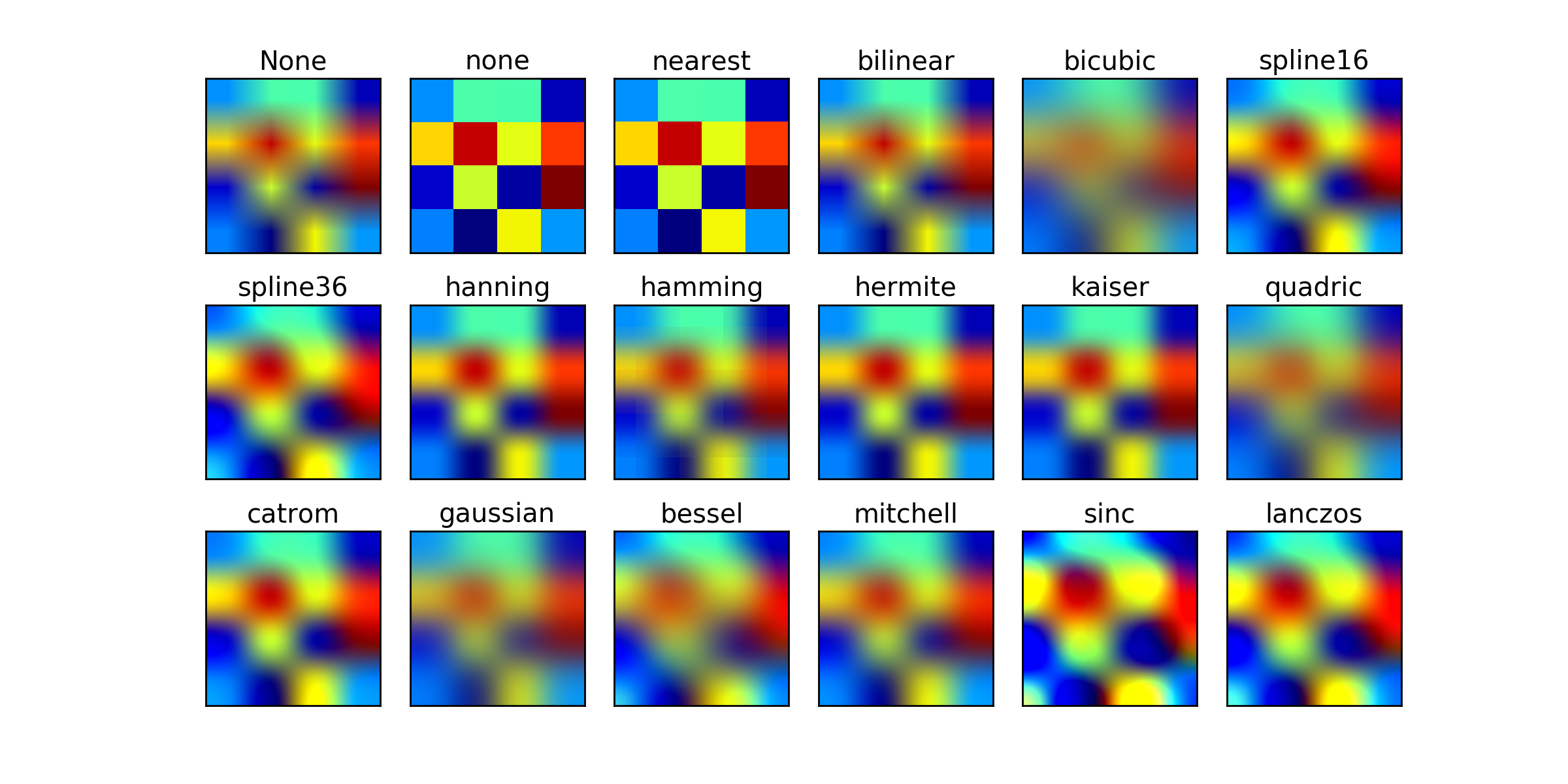
You could try bicubic filtering. That's usually the go-to filter for upscaling. The only problem is that GPUs don't natively support it like bilinear, so you have to implement it yourself in shader with multiple texture samples.
https://matplotlib.org/mpl_examples/images_contours_and_fields/interpolation_methods.hires.png
- Did you review the requirements? Is stretching the image even sensible and would it look good? Would changing requirements to something like "images must be at least WxH in size" solve your problem? This is one possible route
- If you want to use Aero like blurred effect, can you preprocess the image for the first time, render to texture, and later use cached, blurred image? Depending on the amount of elements it could be the best solution — process once when UI element is mounted, dispose when it is unmounted.
- Instead of scaling up, could you consider scaling down/cropping an image that is too big instead? That could simplify a few things.
- Are you sure that user-uploaded image for a backdrop is a good idea here? Won't that introduce a bunch of readability issues?
Yeah I don't have control over the images to enforce any constraint like size.
I tried doing a huge radius Gaussian blur by hand then put into the game to see what it's like, it looks pretty decent. Readability issue is handled.
Texture2D.Apply is a huge bottleneck and it has to happen on main thread, so that's quite problematic even if I moved pixel manipulation to a different thread. Even a tiny image still costs milliseconds.
One approach I tried is to downscale the image to 64x64, Gaussian blur it, then simply use that with normal bilinear filtering. It doesn't look as good as Gaussian blurring the full size image but somewhat acceptable, but even this size Texture2D.Apply by itself is still eating milliseconds and causing a frame time spike.
What about rendering an image to a Render Texture once with a gaussian blur shader when UI loads and reusing it? Are you blurring it on CPU that it's a bottleneck?
it would be miliseconds of the first content paint, later it would be free, no?
Yeah it's only on the first frame.
Is there a way to have a texture act like it's 9 sliced across a model?
images have mip maps, those could be used to your advantage
sampling at a lower mip level to get effectively a blurrier version of the same texture
just an idea but if you want low cost, that is one way to go
Hi there, i'm using a full screen shader to emulate crt scanlines.It looks like this

But when i move the camera Up and Down the effect seems to dissapear until the vertical movement stops.
Im not using motion blur or anything, i've read that it might be the monitor causing ghosting, but im not so sure about that, and maybe here some knows if thats true or not :/
I've also read that it m ight be my own brain processing the moving image the one which is deleting the scanlines out of the ecuation xd. May be i can try to make my scanlines thicker.
In any case, if anyone thinks that what im saying is dumb and there is a simple solution let me know plz ❤️
ITs actually my eyes, i can see them if i stick my face to the screen, srry for bothering u guys D:
Never trust your own brain and eyes 😆
how can i make a mat which is transparent and also shows outline per edge
https://youtu.be/VpIIFdwTKyQ?si=PSDvpF9P53GVIFFu
i have tried this but this doesnt work in transparent mat

We'll take a look at a Screen Space Outline solution for Unity URP. A great asset from Github, shared for FREE from a fantastic developer. This has outlines for colour, thickness and uses layers to occlude other objects. We'll look at setup and a couple of use cases to make some awesome outlines!
➡️Robins Outline Devlog: https://www.youtube.com...
So I'm very new to shader editing and coding in general and I'm trying to do something that sounds simple but cant seem to do it. I just want a line of pixels, while the left most pixel represents the current value of a property, while the rightmost property has the biggest delay before changing to said value, and it be linear between the two. (That sounded more complicated lol)
This outline seems to be based on depth for generating outlines. And transparent materials don't write to depth by default, so you have to force it.
So erm ... a lerp from one value to an other over a line of pixels ?
Ben golus has an awesome technique for this using stencils. Its worth slowing down a little to build an intuition for it instead of copying and pasting. Multipass shaders also aren't supported in urp. But it's a cool technique https://twitter.com/bgolus/status/1482863883626823683?lang=en
I've written "a bit" about doing outlines, like using inverted shells, render texture blurs, or JFA. But there's one more technique I've alluded to in a few places I wanted to share. Offset multi-pass stencil outlines.

how can i force it? i am new to this
that's not what i want
In the shader code file / shadergraph settings, or at the material level (depends on the render pipeline and the shader used)
how can I do a gradient between 0 and 1
- 0 is bottom of the mesh
- 1 is top of the mesh
- 0.5 is the center of the mesh
i suppose you have to use the object position
Yes, you have to use the object position, and remap in between the min and max Y values of the mesh. You can get those with the bounds
okay ty
I'm trying to make a depth outline shader.
How can I make my lines stronger / more pronounced?


I'm trying to get the normals after the skinned mesh renderer deformations. How can I accomplish this?
hey ive been having an issue where in unity 2023.2, shader graph doesnt work. i updated an existing project and it broke all my shaders, and i thought it was a one time thing, but in a new project, it still doesn't seem to work. I did a sanity check by just plugging the sample texture node into the output and it still didn't work. the sprite just doesnt show at all if i have a shadergraph material on it. It seems like the sprite's texture isn't being assigned to maintex for whatever reason
Could show the shader graph with graph settings just to be sure
And as the next sanity check I'd try getting just a color to show
i got it to work. for some reason switching the UV setting for the sample texture off of 2 and then back to 2 fixed it somehow
ok its not working. heres the shader graph:
sorry

Mesh data that comes into shader already skinned. There is no difference between rigid and skinned meshes in shader.
ok i didnt even do anything and it started working all of the sudden. idk whats wrong with unity
UV2? I thought the sprite renderer only uses UV0
What's the point of using Replace Color there
I have no idea what it means i thought it was the dimension of the uv and it was 2 by default
Im using it for an outline so i can highlight interactable objects by replacing the outline color
I prefer it to making an outline shader
I'm super sure it's UV0 by default, which means the first UV channel
That one is generated for the sprite geometry by the Sprite Renderer
you should possibly research other outline methods, such as inverted hull, mesh inflation (vertex extrusion along normal) and writing to stencil buffer or somethhing else. There is only so much a depth gradient can help you with.
blurred buffer with clipping is another option
there are many techniques: https://ameye.dev/notes/rendering-outlines/

🖍️ Explaining multiple techniques for rendering outlines and highlights for real-time applications. This includes vertex object-space as well as screen-space methods. This can be used to render outlines in Unity or Unreal. Outlines can be used for gameplay reasons or aesthetics.
Does anyone have a tutorial or anything on passing vector arrays to shadergraph Or a custom node out there? I'm building an alpha cutout shader that tracks up to 32 objects and cuts a hole in ceiling mesh. It works and I have a script that pools the objects and passes its data to the shader. But this requires me to have 32 vector3 variables (and 32 bools for circle/square, and 32 more for radius/size) and do a massive graph with a bunch of blends to get them all to show. Surely there is a better way? All googling I have done either leads to "no, shadergraphs dont handle that" or writing custom hlsl - but I have yet to find a good tutorial for hlsl arrays. Any guidance is appreciated!
Not a full tutorial but I do have an example here - https://www.cyanilux.com/faq/#sg-arrays
Using Shader.SetGlobalXArray functions to pass the data in. Note if you want a different array per-material, while there is are material.SetXArray versions it ends up being quite buggy in URP/HDRP due to how the SRP batcher works. (But there are ways to break the srp batcher compatibility for those objects if necessary)
Thank you! I'll take a look
Depends on the render pipeline. See Anti-aliasing on the table on this page : https://docs.unity3d.com/Manual/PostProcessingOverview.html
I'm trying to recreate this effect, as an example, where the first pixel is the current value. I did mess with lerp a bit but not sure how to properly use it. However it did allow me to interpolate between the first and last pixel.
Thanks discord for the random blank space under the video 
oh damn, that's your site? It's amazing! I'm even reading one of your tutorials right now xd
They are really well written and very informative, thanks for your work, much appreciated!
I am trying to write a compute shader that adds/overlays a texture decal to another texture. The decal has a TRS. So my thinking was to create a backgroundToDecal matrix (float4x4?) and use that to sample the decal. But not really sure how to handle when the the sample point is not in the decal. Or how to go about making the matrix.
Any pointers or ideas?
Is the decal in world space or are you talking about in texture space?
Uhh... I guess texture space? Basically doing a custom heightmap stamping thing. So the decals are in world space but can/are moved to the main texture space?
can I somehow create a depth prepass, so that I can first write backface depth, then do proper rendering of front face and use the previously calculated depth?
for context: I try to raymarch on a mesh, and I would like to limit ray to the backface of a mesh, so it doesn't march "past" the mesh. Ofc this is a generalisation that should only work for convex meshes, but it's good enough (and if someone knows how to do it for concave meshes I'm very eager to know!)
Hey I just started learning Shader Graph coming from programming. I'm curious about Shader Graph as a tool and visual scripting in general, how do you keep everything organized? Even with a very simple shader I feel like the whole thing becomes messy and unintelligible extremely quickly, I can't imagine how a big complicated production shader looks like and how people can actually work with it. Do you have some advice on how to organize things inside Shader Graph? Do you have some screenshots of more complicated shaders to show how it's organized?
Thanks!
Also, is using Shader Graph required (or heavily recommended?) or could I create the same shader by just writing code? Shader Graph doesn't seem to be doing anything special, it is just an algorithm at the end of the day.
It is not required. Anything that hadergraph does you can do by hand, given you have a lot of time to spare. You can see generated shadergraph sources. They are often shaders with more than ~2k lines, excluding the includes. There are also a lot of corner cases you might not think of, that have been already dealt with by the shadergraph team.
is writing them by hand practical in any real world scenario? or would I be silly to do this? I have no experience to be able to tell.
a lot of shaders are hand written because the expressiveness and fidelity of such code is far greater than what shadergraph can produce, but there are also a lot of shaders made purely in shadergraph. I think the main point is that you should use appropriate tool for a job. If you can do something in a shadergraph and be happy with it, go for it, but if you need more fidelity/control/performance/pizzaz, you might consider writing your shaders by hand. Reimplementing a shadergraph shader by writing it by hand "just because" should rise some red flags. Hacking around with nodes in shadergraph to achieve something you could implement in one function should as well.
And a quick example of things you can do manually that is hard (or impossible without custom nodes) in shadergraph (for now): for example raymarching shader.
I see, thank you for the explanation. So in a game project it could happen that some shaders are written by hand and some are made in shader graph for a single game.
Thanks to this post I got the shader mostly working. The array portion is atleast passing data!
Yup. I've once been in a project, where shaders generated by AmplifyShaders had to be hand-tuned, because they had some problems with z-sorting etc. So as you can see there are even hybrid cases wth correcting by hand generated shaders xd
As for organizing, idk, that's a question to someone else. The only thing I can point to are SubGraphs
Trying to figure out the last part of this shader.
Its an alpha cutout shader that applies up to 32 holes in an object based on other objects positions. I thought I was transforming the positions of objects correctly onto the plane(ceiling).
Oddly enough if I have a plane scaled to .3048 x.3048 it works 1:1 with the objects position. If I scale the plane back to 1 or move it, the holes no longer follow the objects position. I assume its how I'm transforming world space coords to object/UV space. Anyone have a good example of how to apply effects to a material in worldspace?
I had a usecase like this and it can be handy to duplicate the Amplify template your shader is based on, tweak the settings in it and switch shaders to use it. Reediting the generated shader after every change in the Amplify graph sounds exhausting 😆
(Every Amplify template is a text file in Amplify folder)
iirc it was a one-off change, that was made for a feature that lasted for, like, a month until it was scrapped or reworked. The funny part was — the artist had Amplify Shaders package and I didn't, so I was basically working with what I could use at the time :D
(good to know though that the templates can be swapped!)
Use subgraphs, split shaders into big chunks of functionality that are separated into subgraphs. At least that's how I deal with having to maintain giant monstrosities.
is there a good image or post describing each element of the UNITY_MATRIX_P?
And is near plane the same as focal length in regular (non-physical) camera?
asking in the context of https://github.com/hecomi/uRaymarching/blob/master/Assets/uRaymarching/Runtime/Shaders/Include/UniversalRP/Camera.hlsl,
because GetCameraFocalLength, GetDistanceFromCameraToNearClipPlane look magic to me, but they supposedly work
https://streamable.com/97s5ub anyone have any idea why these particles are doing this? they'll disappear once they're outside of the player's direct view

i figured out that it only does this with the blood shader that I have on the material, so i'm guessing it's something I need to change there
this:

Does anyone know how to make like half life 1 flashlight style fake lighting? Like there isn't any actual nonbaked lighting but there's a circle of area in front of you that is lit up
Hi, I want to make a pixelart 3D shader with shadergraph. Currently I use an asset called propixelizer, but have a small issue with it. Right now, the pixel's amount change based on how close the camera is to the object, and how I want my shader to work is to have a consistent amount of pixels, and the pixel count should only be changed by an input field. Would this feature be possible to implement, or should I just ditch the idea?
Those are both totally valid approaches
Might anyone know how I can disable the player's reflection from a shader?
(apart from putting it onto a new layer?)
I'm planning to do the player reflection separately, so just wondering, thanks!
I've asked this before, but I can't wrap my head around this. Imagine I have a shader for folliage with a little sway, and another for props, and a third triplanar one for texturing terrain or terrain features. Now if I want to add "wetness" based on some parameter for everything in my game I would need to add it to all of my shaders? Is there some way to "composite" effects other than re-using subgraphs in shader graph for example? Or making an "uber shader" that you use on everything with different parameters?
What's your approach / convention for adding "features" to all your materials?
You could make a modular HLSL header with wetness calculations that take structs with input data and modify the passed in PBR surface parameters. This would let you reuse the same wetness calculations across a bunch of unrelated shaders by including the header and invoking the wetness function. The only duplicate work across shaders would be copypasting the pragmas and properties for wetness across all of them.
(I don't like ubershaders)
DISTORTION SHADER
does anyone know how to make a shader graph distortion shader in hdrp?
i tried to search (ctrl + f) here but no one give a real solution. they all say that in URP is different, ok. But what's the soolution in HDRP?
Can't find Vector1 in Unity Shader Graph. Should I use Float instead of it?
Yes
Hi folks, I've opened up 3D game kit and all the surfaces are blue, how do I turn this off?

Not really a shader issue, it just looks like the navmesh are visible 🙂
I've searched on google for like an hour solid lmao
omg I've done it
guys how do i make so that the only light thats in my scene is only from the light souces i make? currently everyone isnt black when i turn off all lights, instead its a a very ugly brown colour bg, and it colours all objects to that ugly colour


how do i disable it
Change the skybox, or turn down environment lighting in the Lighting window.
where
In the Lighting window
Surface shader to urp
Hello ShaderNerds ;
I have Project where I am using a custom surface shader for my terrain written in HLSL it is the only shader I ever made myself so my knowledge about shaders is very poor. The shader was working fine and I am amazed that it does...
WHAT ITS DOING:
blending textures based on terrain height and steepness + plus adding colors and applying triplanar mapping (terrain is a custom mesh)
WHATS THE ISSUE:
I am now converting my project to urp and sadly urp does not support surface shaders. So I guess I have to convert it into another type of shader. So I am wondering what type of shader should I use? (Preferably one which would make it easy to include normal maps at some point later on). Where can I find help/instructions on how to do it ?
Much thanks in advance
@sly steeple you should be able to recreate it in Shader Graph. I even managed to make a shader usable with the builtin terrain system.
Can someone help me out? I've created this subgraph with a custom node that takes in a world space position and radius - It is working all as intended except the circles and squares that are being cut out of the ceiling don't follow the position of the objects its linked to perfectly. The farther from the center of the object being cut the tracked object gets the more off center it becomes. Any ideas on what I'm doing wrong?

I should mention this is HDRP so absolute world is necessary
the above graph then gets blended 32 times with identical other subgraphs in the main shader
who here wants to teach a person how to shader in vc? i know mostly the concept of shaders from youtube vids but i have never seen any of them walk through on how to actually setup stuff and the "boring stuff" of the process, cuz technical content doesnt get views they crop out most of it
hey there friends! Quick question: How can I Google this effect? So basically, "a shader that makes the borders of the mesh visible regardless of position" - just like in the editor

For the border, there's a bunch of techniques for "outlines". They're pretty common, but not necessarily an easy topic. This lists most of them : https://ameye.dev/notes/rendering-outlines/
If you want it visible through objects look into using ZTest Always and compare with depth texture to reduce the opacity, or render as two passes (one solid with ZTest LEqual and one slightly transparent with ZTest Greater)
🖍️ Explaining multiple techniques for rendering outlines and highlights for real-time applications. This includes vertex object-space as well as screen-space methods. This can be used to render outlines in Unity or Unreal. Outlines can be used for gameplay reasons or aesthetics.
@regal stag thanks that looks like a great place to start
Why do you need to offset the UV with the calculated position.xz ? Shouldn't you just use the XZ output of that subtract node (btw, using a swizzle node here will reduce a bit the nodes count 🙂 )
I thought the offset would place it on the object at the calculated position. If pass the calculated position (now using swizzle thank you) to the UVs of the rectangle or ellipse its even farther off the tracked object
That "UVPos" output is supposed to be the position of the controll object that cuts the hole, right ?
Yes. I have a script passing in the world positions of the objects
UVPos is just the world position of the object (poorly named I know)
The whole thing gets build up to 32 objects like this (I know this is ugly, cant figure out how to pass all 32 in one loop)

So, the graph should be correct, 🤔
With the exception that the rectangle and ellipse expect to draw in the 0to1 uv range, so you should probably also add (0.5, 0.5) to the calculated position.
You could just make all the cutout code in the custom function, and do a loop in the code there directly 🙂
right but then how to I pass all 32 into that code?
You pass the world position to the custom node, and loop through all the indices
Right I get that. I even have the code already there but commented out because i couldn't wrap my head around it since you're not "doing the thing" in the loop.
{
    float3 _UVPos = 0;
    float _radius = 0;
    float _isSquare = 0;

    _UVPos = float3(_Worldpositions[index].x, _Worldpositions[index].y, _Worldpositions[index].z);
    _radius = float(_Worldpositions[index].w);
    _isSquare = float(_isSquared[index]);

    UVPos = _UVPos;
    radius = _radius;
    isSquare = _isSquare;


    //[unroll]
    //for (int i = 0; i < 32; i++)
    //{

    //}
}```Ok i started to look into shader graph a little, so when creating a new graph i have the option between unlit and pbr. From my understanding unlit would be just fine for what my shader is doing currently(?).. but if I want to add normal textures later I might have problems correct? So I m wondering, can I basicly treat the pbr like the unlit for now and just use the pbr graph so I keep the otption availibe to add more complex shading stuff later or is there something I am missing ? Like drawbacks in performance or sth?
EDIT I am not using Unity Terrain
adding .5 to the tiling worked! You're a life saver!!!!
Final graph for anyone else searching for an answer

You could just look at shadergraph doc to see what code the nodes are actually doing 🙂 : https://docs.unity3d.com/Packages/com.unity.shadergraph@17.0/manual/Ellipse-Node.html
oh thats fair... Going to give that a shot. Thank you so much. I have been stressing getthing this to work for DAYS!
If you want PBR lighting, you should pick the Lit graph type. If you don't want any lighting or want custom lighting, pick Unlit.
Here's a very quick modification of the code you've shared higher to do what you wanted :
void ExampleOutput_float(float3 worldPos, out float mask)
{
    float3 _UVPos = 0;
    float _radius = 0;
    bool _isSquare = 0;
    float2 uv = float2(0, 0);

    mask = 0;


    [unroll]
    for (int i = 0; i < 32; i++)
    {
        _UVPos = _Worldpositions[i].xyz;
        _radius = _Worldpositions[i].w;
        _isSquare = _isSquared[i] > 0.5;

        uv = (_UVPos - worldPos).xz;

        if (_isSquare)
        {
            float2 d = abs(uv) - float2(_radius , _radius );
            d = 1 - d / fwidth(d);
            mask = max(saturate(min(d.x, d.y)), mask);
        }
        else
        {
            float d = length( uv / float2(_radius , _radius ));
            mask = max(saturate((1 - d) / fwidth(d)), mask);
        }
    }
}
@wary scaffold
Yes but I mean I could do everything in the pbr graph; which I can do in the unlit right? Since for now I dont want custom lighting, but i might want to add it in future iterations (when i am less clueless)
Thank you. I had to remove the "float" from before the mask = 0 to fix a redeclaration and change index to i in the for loop. It now gives me another error - "No Matching 1 parameter intrinsic function - line 52" I assume worldPos is supposed to be _UVPos? Also says Width and Height are undeclared. I'll have to dig into how to get those.
Yeah, sorry, I realized later I had still errors (I didn't try the code in editor), it should be fixed now
It still throws Width and Height as undeclared identifiers
I did just remove them (using _radius instead)
I had to change void to float but it then compiles correctly.
for the UV input I assume that is just the UVs of the object.
And would the mask not need to be mask += since its otherwise overwriting it and only returning the last result?
Instead, I removed the return statement, that's more what SG expects.
Th uv ... as, sorry, I forgot to do this math, let me fix it.
@wary scaffold updated
And would the mask not need to be mask += since its otherwise overwriting it and only returning the last result?
Not really, since at each loop cycle it is taking the max value between the previous mask and the new shape, so they "stack"
Thank you so much!! I can't tell you how much I appreciate it. This has been plaguing me for days! If you have a patreon/youtube/whatever please let me know. I feel like I need to buy you a coffee or something.
Thank you, but I have none of those 😅
Well if I can ever repay you lmk! I've learned more in the past 30 minutes from working through that then days and days of doing my own research and trying to hack things together. Heck I'm amazed I almost had a working subshader. And thats only thanks to Cyan's excellent tutorials on their site.
I am in the process of converting my surface shader to shader graph (absoluty first time using shader graph). Regarding the shader graph Inputs :
I can input tex2Darrays nice✅
I cant input a simple float array ❌
I cant input a color array ❌
I feel like there "should" be way to do it?!?
Like for surface shaders, you can't expose float or color arrays. In shaderlab code, you declare the arrays properties in the HLSL code. You can do the same in shadergraph through custom function nodes and HLSL includes.
ok i will have look at includes than. So I simply have to declare the arrays I need in a separate hlsl file which I than can somehow need to include in my graph, so I can use material.SetFloatArray and material.SetColorArray? Thanks
I am just lost now so this are my properties in the surface shader:
const static int maxLayers = 8;

int layerCount;
float3 baseColors[maxLayers];
float baseStartHeights[maxLayers];
float baseBlends[maxLayers];
float baseColorStrength[maxLayers];
float textureScales[maxLayers];
float steeptextureScales[maxLayers];
float steepMulti;
float steepThreshold;
float minHeight;
float maxHeight;
UNITY_DECLARE_TEX2DARRAY(baseTextures);
UNITY_DECLARE_TEX2DARRAY(steepTextures);```Example for the baseColors:
float3 baseColors[maxLayers];

void GetBaseColor_float( int index, out float3 baseColor )
{
  baseColor = baseColors[index];
}
Thats exactly what i have tried, but it would through an undeclared identifier error upon saving the graph
What was not declared in the error ?
i think base color but give me second i will try to reproduce it
ok I cant reproduce it (tried to many things to remember); I just used your code snippet now and I get unexpected token "(" at line 164 I made screenshot of how I set up the Node; thanks a lot for helping my frustration level is peeking at the moment 😄
That error does not make sense to me at all

Don't use the string type for this workflow, you need to write the code in an HLSL file, and include that file in the custom function node using the "include" type
The error you have is because when the node it set to string type, it wraps the written code in a function already.
And when using the include type :
- The function name will have to be "GetBaseColor"
- Force the precision to "float" : the precision is appened to the end of the function name, resuling in the one declared in the hlsl
Ok that does make sense; thank you I will take a break now and try this later. I was using string simply to try stuff out quickly. I was really lost and could not find anything. By the way, when i include multiple of these functions in one file can I than control which one is called by changing the name inside the inspector accordingly? It seem a bit messy to have one file for each array and also as final question, does it even make sense to do what i am trying with shader graph?
when i include multiple of these functions in one file can I than control which one is called by changing the name inside the inspector accordingly
Yes 🙂
does it even make sense to do what i am trying with shader graph?
Yes 🙂
ok, thats a little motivation. I started to think, that if there is no support for arrays there is probaly a reason for it
Reasons are multiple, but to sum up the starting point of it : because they can not be exposed as properties with shaderlab code (that is what shadergraph generates), it was nat added to shadergraph options when creating properties. And the only workaround to use them is to do like in shaderlab : go through hlsl variables declaration
Yeah, sure, you can do anything.
i want to make an image like this that is fully transparent at the top but not transparent(or a little) at the bottom

how do i do it?
im talking about the one behind the dialogue
idk if its with a shader, i just didnt know where to ask this
Just use a PNG
good idea, thanks
what should i type in google
idk how to describe that image
create it yourself
how
with photoshop or something similar
i dont have ps
i have a pixel art software
ill try
or google for something like alpha gradient png
all of them are fake pngs lmao
https://pngtree.com/freepng/black-gradient-vertical-gradient-element_5441580.html
that seems to be fine
thank you it worked
yw
Thanks for the help.. I am giving up for today at least my landscape looks kinda interesting now 😄

Is there anywhere I can find a shader graph version of the Unity standard shaders? Specifically the standard URP lit shader for my usages, but I want to extend it with some new options without breaking any of what makes the shader do what it does
Im very confused the standard lit shader would be a lit graph with the proper textures hooked up
A brand new lit graph already does everything the lit shader does
anyone knows why my image half dissappears from certain angles?

Mostly I just want to avoid having to either A) rewrite code to use the new shader properties or B) Copy over every shader property's name and defaults by hand into the new graph
Just would be convenient if there were premade graph versions of the existing shaders to base it off of
That would be convenient indeed
We have a nice little library of subgraphs that we have made and reuse in most projects
Including a pbr one where it just hides all the sample texture nodes and sliders
Hm, the PBR Node seems to be missing an obvious hookup for the height map.
I think it shows up if you enable it in the graph settings
Okay so it's got to be more involved than just plugging in the maps into the slots because these two things look very different

Even removed the heightmap from the right-cube since I don't know how to replicate it
Heightmaps would be used by the Parallax Mapping node (Unity 2020.2+), it should alter the UV coordinates used by all the other textures
Or Parallax Occlusion Mapping, more accurate but more expensive too.
Okay, that does seem to have applied the heightmap. Do you know what else is missing to replicate the standard URP lit shader?
Same set of textures, what I can assume is a pretty straightforward shader


Is the normal map applied? Not sure they look correct.
Make sure you set the Type on the Sample Texture 2D node to "Normal" for that one
Yeah, it's applied and it's the same asset
Oh, in the node, I had changed the texture, but not the node. That did it

thank you
Hi, how can I create a billboarding shader that can also be rotated (similar to creating a Particle System with a billboarding texture with rotation)? I have this series of nodes that can get me rotation, and another series of nodes that can billboard, but I'm not sure how to combine them. Thanks


Would it work for you to do a that rotation before you billboard it?
Right after that multiply in the billboard group.
ah nvm got it to work with a bit of a hacky thing! 🙂
Pasting the steps below --
I was following this tutorial here: https://www.youtube.com/watch?v=ym1K3of3pys
I followed the chapters till / including the "reflection" section, the only differences I made were --
-
Place the player on a separate layer, called P as an example.
-
Make a new camera, C, the size of the player roughly. Set the culling mask layers to be only P.
-
Create a new sprite, and make sure it equal to the size of C, and place it right under the player.
-
There is a white background texture. that will be there by default. I'm not sure if there is a way to get rid of it (see screenshot attached), so what I did was instead set the alpha value of the reflection sprite to be very low, so that the white box appears to be invisible 🙂
This is the shader graph, in case it may help anyone facing a similar thing out ! 🙂
Attaching the final result as well!

Learn how to create a water refelction effect in Unity
Download the project starting files at https://drive.google.com/open?id=1OUOcx75_fm-1yZb6rSt8siWEYWJrdUe-
Inspired by Binary Lunar: https://www.youtube.com/watch?v=O1lRGKfCi9o
Get my latest Udemy course 'Learn To Code By Making a 2D Platformer in Unity & C#' at https://www.udemy.com/cours...
Is there a way to apply a screenspace effect BEFORE lighting?
I want to apply an outline to some objects but make that outine susceptible to lighting/post processing.
It would be better to use the inverted hull method for this since then you have a mesh to actually apply lighting to
Unfortunately I don't think inverted hull would suit what I'm going for. For context, this is the current concept I'm looking to replicate. The style is heavily dependent on outlines and simple, flat coloring, and I'm looking for ways to get an outline on the 3D geometry that would make up the levels.
Other outlines, like on the sprites and the floor, are just from a texture.
Honestly these outlines look like they are authored in the texture
Well, I can confirm this is not the case, as this whole piece was hand drawn by my concept artist 😛
So they are in essence authored in the texture 🤣
So true
but ya, working to try to replicate this style
and the outlines on the 3D models are giving me trouble
I'm generating some procedural meshes using ComputeShader, and then I use this VertexShader to map the faces on a texture. Does anyone know if I can change the texture at runtime by setting it through a script, and how can I do it? So far I've tried material.SetTexture("_MainTex", Texture) but it doesn't work

I have to say that you will not get close to replicating clean and thoroughly placed outlines like this with an algorithm. Well maybe some AI driven post processing can come close but still. Sometimes the work has to be put in and done by hand.
Define the texture as a exposed asset in the blackboard and then you can use its reference name to set it from a script
I'm not looking to automate every line, just ones around the edges of walls. Patterns and markings on the floor will definitely be handled by regular textures.
like the lines you see here, for example
Ah you can get decent one like that using the goodnold depth normals technique
But again… you want then to react to lightning that is tricky
ya I'd want them to basically act as if they're textured 😛
I dont think its possible without extra geometry to be honest
Surely there's some way? Can I not just apply these outlines to the image before the lighting takes place?
Like some custom render feature.
In a deferred renderer it could be possible to take the same approach that deferred decals do. You would render out all opaques, get depth and normal, calculate the outlines and somehow apply that data back to the g buffer
For a forward renderer Im not sure
if the outline is black, wouldn't lighting be pretty much has no effect on them?
I mean, a black color with white light would still look black
So turns out Im a bit rusty on my computer shader knowledge. This particular shader essentially needs to read from one array and write to another, both are 1d and the same length. Now I know it’s a good idea to keep thread count to 64 or a multiple of that due to wavefront occupancy and what not. Since we are talking 1d arrays here I don’t need the extra dimensions and can just go for [128,1,1] in the shader. However I cant seem to figure out how to properly calculate the thread group size for the dispatch since for every dispatch the arrays can be of different sizes
Im not sure what happens if I dispatch more than I need so array.lenght/128 rounded up doesnt seem to be a good idea
I've usually seen (64, 1, 1), or (8, 8, 1), so 64 max.
Hi got a question
I basically need an Unlit shader for BIRP... Is there any available online?
You will have extra threads unless it divides cleanly with the thread count. You need to keep that in mind in your shader. If you end up reading or writing outside of bounds, that's fine, it's just a no-op. But if it can have actual consequences, you'll have to add a bounds check to exit early.
Ah reading and writing out of bounds is no problem ?
How would I do a bounds check, if id.x > arrLenght?
Yes
And just what return ?
Sure
Unity can't guarantee it will be safe, it will depend on the graphics library and the GPU. Some libraries guarantee the behavior of out of bounds access, like DirectX 11 will always return zero. DX12 seems to have different behavior depending on the type of resource accessed. Vulkan is undefined behavior, so it should be avoided there.
Ah I also sample a texture in there so better be safe
Should already be an unlit shader on the Shaders dropdown when you create a Material asset.
Or if you need a custom shader to edit it further, Create->Shader->Unlit Shader creates a template for BiRP (unlit + texture input)


looks fine, whats weird?
look at the zombie itself

this without and with the material
see whats wrong?
What are you applying the shader to? A sprite renderer?
just trying to output the current texture in the sprite renderer
nothing more
i guess changing the wrap mode to "clamp" in the import settings of your zombie could work there
Should use one of the Sprite type graphs then (can switch it under Graph Settings). That'll expose the Alpha port where the A output of the sample should connect
ohhhhhh
I'll try ty
but just one question, I tried and it worked but like in the preview of the shader itself it still is a bit weird
do u know why it gets this effect

It can look weird, but normal to look like that. The previews within shader graph show the RGB data, not any transparency/alpha. I think most programs don't save colour data in fully transparent pixels, and Unity also can stretch colours out during import to avoid artifacts (particularly when using bilinear filtering rather than point, but still applies)
thank you! gladd to know
How would I go about making a shader to make the texture shake
been trying for a while
What kind of shake are you thinking? You could just offset the uv with a noise and time value
just a really small shake like the enemy has been tased
I'll try to use a noise
maybe with a smooth step?

I cant do it like this can I?
Try plugging time into the uv slot on the noise
And adding another noise
Then combining them into a float2
And subtracting .5 from the value to make it go from negative to positive.
thats smart, thank you I will be trying
Ill let u know
Sweet!
the shaking itself is working
I just have a few questions if its not bothering
Ya go for it!

if I would like to make a sort of if statement to turn on and off shakeyness
what could I do?
didnt understand very well what to do with branches
like Im used to the big brain but the big feet is kinda new and the big brain doesnt appear on the sprite

Another way to do this if it's not very often would be to make the shake happen in c#
Instead of in the shader
Hm. I don't think I know enough about your project to say about long feet. Does anyone else know?
yah Im gonna change the shakeyness value change thru c#
but if I put it 0 its very intense
so I would need to like set it to 10000
to make it not visible

this is how I made the shaking

the rest
If you make shakiness a multiply instead of divide it might be more predictable.
basically I just want to have a powerup that has a chance to stun enemies
and they shake
when stuned
thats it
ur right
I shouldnt be dividing by 0
But also you could use:
https://docs.unity3d.com/ScriptReference/Material.SetTextureOffset.html
In c# and do your noise calculation there and it won't run all of the time.
thats good, I think I solved it by just setting it to multiply
Woo!
cuz I can just make the shakeyness 0
thank you so much, Im just now starting to mess with shader graphs
is coding shaders that much harder?
I enjoy coding
but I aint sure
There's a bit of boilerplate with unity but it's how I learned!
I recommend the book of shaders. It's glsl and not unity but it's super helpful. https://thebookofshaders.com/

The Book of Shaders
Gentle step-by-step guide through the abstract and complex universe of Fragment Shaders.
And easy to bring back to unity too.
Just slightly different syntax
hmm sounds a good place to start thank you!
Using Forward+ on my project makes all my shaders glitch blinking/flashing in black and white, anyone else has this issue?
Anyone know why a material is much darker in a project loading it from an asset bundle than the original? I have two projects, one of them is for exporting material bundles, and the one that uses them. I have the same shader in both. The first image shows it as it's exported from the bundle generation project, the other is the result in the actual project. Both are lit by a directional light and you can see how much brighter the ground near the applied bundle is. What could be making this material so much darker?


I just recreated the material, same textures and shader, and it's still dark so it's obviously something to do with my lighting or project settings. I just don't know what that could be

I'm having trouble drawing my object in the center of the camera.
I try to set the vertex position to the center of the camera, but this doesn't work.
o.vertex = UnityObjectToClipPos(_WorldSpaceCameraPos);
What is wrong?
Right now your code is setting the output position of every vertex in your model to the same point: _WorldSpaceCameraPos after being transformed by the Model View Projection matrix (UnityObjectToClipPos()). If you want your model to keep it's shape you should have v.vertex somewhere in your equation.
If you wanna center the vertices in the camera using _WorldSpaceCameraPos you'll want to first transform your model from object space to world space like this float4 worldPos = mul(v.vertex, unity_WorldToObject); then you can subtract the camera position from it worldPos -= _WorldSpaceCameraPos; and then transform it back into local space float4 localPos = mul(worldPos, unity_ObjectToWorld); then run your o.vertex = UnityObjectToClipPos(localPos).
This will probably give you a result where the camera is inside of the object so your next steps would be to figure out the camera forward vector and add it to your world space position.
This approach adds a lot of complexity for centering an object on the screen but might be good for just figuring out how matrices for rendering work. Usually for stuff like this I prefer to transform things in C# since it won't break frustum culling.
If you wanna learn more about matrices for rendering I recommend: https://catlikecoding.com/unity/tutorials/rendering/part-1/
It's also worth it just to mess around and try setting o.vertex = v.vertex; -- this will give you the model space position on screen. It'll squash and strech with the screen since it's not scaled by the aspect ratio of the camera (that happens in the projection matrix).
You could theoretically do all of this centering logic with just the Model, View and Projection matrices.
A Unity Rendering tutorial about matrices and transformations. Part 1 of 20.
Hi all, does anyone know if it's possible to write to a uav 3d texture in a fragment shader? I'm having issues doing so.
Here's the binding: RWTexture3D<uint> _voxelScene : register(u1);
And I simply want to write to pixels where my fragment lands in clip space: uint3 pix = IN.positionHCS.xyz * 16; _voxelScene[pix] = 0xffffffff;
However, the texture appears to be empty when rendering 😦
The texture descriptor in case i've made some mistake here: RenderTextureDescriptor voxelSceneDesc = new RenderTextureDescriptor() { width = voxelSceneRes, height = voxelSceneRes, dimension = TextureDimension.Tex3D, volumeDepth = voxelSceneRes, enableRandomWrite = true, graphicsFormat = GraphicsFormat.R8G8B8A8_UInt, depthBufferBits = 0, msaaSamples = 1 };
And binding on unity side (dummy target is a normal 2d render target): cmd.SetRenderTarget(dummyTarget.depthBuffer); cmd.ClearRenderTarget(true, false, Color.clear); cmd.SetRandomWriteTarget(1, voxelScene); context.ExecuteCommandBuffer(cmd); context.DrawRenderers(cullResults, ref drawSettings, ref filterSettings); cmd.Clear();
I've set the shader model target to 5.0 in the shader too, from what ive read this should support writing to uav textures
UPDATE: I've solved the issue. Turns out theres a funny behaviour where you have to call ClearRandomWriteTargets() both before and after rendering, idk why this is so but my shader works now 🙂
If anyones interested (Im super proud lol):
this is such a cool idea!! I didn't realize you could write to textures from within a frag shader like that. is this mostly for organization?
Thanks! I'm planning on implementing realtime voxel cone-traced GI system for indirect illumination for a project of mine. For that I need to represent the scene as a voxel grid, so i'm using a custom shader which writes to an 3d texture (seen above) to do this. I was super worried I wouldn't be able to do this in unity so this is a massive releif. If youre interested this is the paper im basing this off (my implementation will be alot more simple tho): https://research.nvidia.com/sites/default/files/publications/GIVoxels-pg2011-authors.pdf
I'm reading a RawBuffer in a custom function node like this ```ByteAddressBuffer _woundBuffer;
void ReadBuffer_float(float i, out float clip, out float blood)
{
uint packedValue = _woundBuffer.Load(i * 4);
clip = (packedValue >> 16) / 65535.0f;
blood = (packedValue & 0xFFFF) / 65535.0f;
#ifdef SHADERGRAPH_PREVIEW
clip = 1;
blood =0;
#endif
}```
problem is that the preview works in the graph, but in the scene view the mesh totaly disapears because the clip value that goes into the alpha is 0
Can I somehow define the buffer without doing custom code in lets say a Initialize on load or what ever
hmm initing the buffer and filling it with data in Reset does work, but the workflow is scuffed
lol ofc I release the buffer in OnDisable, so exiting play mode means you have to reset the component again....
I started a project in 2022.3.4f1 and decided to open it with 2022.3.19f1 to make sure I'm up to date. but this happened to my skybox shadergraph... does anyone know what happened?

whats the best premade shader outline package to use?
I tried to follow a brackeys tutorial on shader outlines for 2d sprites,
but i'm guessing its old because the GUI he went through was completely different and I cant figure out where to create the same shader type.

Thanks to NVIDIA for sponsoring!
Learn more about NVIDIA Studio► https://nvda.ws/38AaA8K
Razer Blade Studio laptops► https://www.razer.com/studio
In this video we create outline effect using 2D Shader Graph!
● Learn more about 2D Shader Graph: https://youtu.be/5dzGj9k8Qy8
● 2D Glow Tutorial: https://youtu.be/WiDVoj5VQ4c
● Get Gothicvania Ch...
Which rendering pipeline are you using?
URP asset (With 2D renderer)
then the video tells you to delete the smaller one and create URP 2D renderer
then edit , project settings, new universal render pipeline asset ( universal render pipeline asset)
Something to do with the extra passes SG generates. Setting Surface Type to Transparent under the Graph Settings appears to fix it
in the video he goes through this path
but i cant find this


thanks :D
Check under "Create -> Shader Graph", they were split under a new heading
i did try creating an unlit shader graph there but i assumed it was different because our things look different and have different components


That's just what it looks like in newer versions, it's the same kind of stuff, just organised/renamed a bit differently.
Might also want the "Sprite Unlit" graph to match the one the tutorial uses (can be changed under the Graph Settings tab on right, no need to create a new graph). Regular Unlit might also work but is intended more for 3D objects.
I didnt read properly and missed the part where you mention 2D
try re compile it
where am i supposed to drag it?
brackeys one on the left he drags it into color
but thats not an option for mine, and my one doesnt do anything if i drag it into the closest thing


I'm doing a blinking shader and wondering how i can just make a shader without the material? Let's say I want a gun with a texture. I just want that texture to blink so the player knows it's an interactable.

both is the same
his one already shows the sprite if he goes back to main, while mine does this
(bottom left one has the shader on it)

Base Color is correct, but you'd also want to connect the A output to the Alpha port.
I think the Main Preview at the bottom is just bugged... I'd just hit the Save Asset in the top corner and check it in scene/game.
oh :3 i didnt save it
Shaders are always applied to materials. (Doesn't necessarily have to be the one created automatically under the graph though)
i guess ctrl S doesnt work and u have to manually press save asset
Yea
Thanks. How would I make a blink shader to be able to use on another material?
On each material asset there is a shaders dropdown where you can choose which shader it uses
I did but it won't change it. I'll send a screen shot RQ
Please don't slaughter me. :p

Looks fine to me, what exactly is the problem?
using this as an example. This has it's own material and is using the URP Lit shader


If i change it to my blinking one. it changes the material too
Right okay, you need to provide the same texture inputs and sample them in the shader
At the very least, _BaseMap is the albedo/colour texture
So I cant have 1 blink shader for all?

This works, Was just thinking I can use 1 shader for every interactable
If you use a Texture2D property in the blackboard you can expose the texture on the material so it can be swapped out, same as the URP/Lit
I have 0 clue what that means. Could you point me in the right direction so I can look into it please
the issue was forward+ compatibility, added to the shader now :P but thank you anyways!
TYTY
any idea what i did wrong? the whole square is lighting up
its supposed to just be an outline

- you do realise that the "clamp 1, 1) is useless, right ?
- that last add is probably the culptris, resulting in values over 1 and non transparent pixels
in the brackeys video he said the clamp after the add was specifically to stop values going over 1
But from my understanding of what you have and what you probably want :
after that clamp (that could be replaced with the "Saturate" node) :
- output color is : lerp from mask color to sprite color using sprite alpha
- output alpha is : the current outline mask (the output of the clamp/saturate)
The clamp node restricts the input value to the range bewteen A and B. If you set both A and B to 1, the result will always be 1
oh oops its meant to be 0 and 1
Just use saturate node. It's a shorthand for "clamp( t, 0, 1)" 🙂
alright ill swap it out
this is it currently now
i probably did something wrong on the left, ill just go through the tutorial again i guess

Show you current nodes setup close to the output, with the corrections I proposed
Why a video, a simple screenshot would have been enough ...

Try this :

tried to follow the image but its difficult lol
I guess thats on me for bad layout

Almost there

heyyy! awesome, thanks!
This a shader for a simple square image that is acting as the fill part of a slider but.... the patterns are scaling to the size of the actual thing, which I want it to reamain constant, does anyone know how to do that?

This is the shaderGraph that is generating this

If it is worth something
There's no way to created instanced properties with the shader graph, is there?
I just noticed that I have tons of tiny draw calls because instancing is being broken by different values in my material property blocks
Kinda. Can do it with Custom Funtion nodes. e.g. https://www.cyanilux.com/faq/#sg-gpu-instancing
But if you're using URP/HDRP you're meant to avoid MaterialPropertyBlocks as the SRP Batcher doesn't support them.
this is an HDRP project
but I'm deliberately trying to do GPU instancing here
i'm drawing lots of copies of the same mesh
this is for drawing debris
Although, in non-pathological cases (i.e. when I don't spawn tons of copies of the same debriso bject), it's more heterogeneous
Then yeah try a custom function. I've only tested it in URP but might work in HDRP too
in which case the SRP batcher makes more sense, probably
I didn't know you could declare properties in a custom function like that
Using a Position node or Screen Position instead of the mesh UV might work
I am trying something like that, the position node should be connected to tiling input at the beggining, right?
You'd put it into the UV port not Tiling.
Also, the Tiling And Offset node in your screenshot above isn't really doing anything. I think it's going into a Float port so doesn't make much sense. I assume the node after that is a subgraph which generates the striped pattern, that's where you'll need to make changes.
The Tiling and Offset is supposed to do the tiling, rn, is just doing the offset for the overtime animation
The Stripes I think I literally downloaded it from the basic unity addons, and does this

So.... I am guessing the tiling I need to input based on the scale should go... into the frecuency???
Okay, that inital UV port on that Rotate node is what you'd want to change
Oh, how do I... input that without breaking all other shaders that are using this component? XD
Could copy the subgraph asset if you need the original
Or copy the nodes into your main graph
Mmmmm.... I think I got it, but I don't think it can work with an interface since its scale is kinda weird realte to the world position
Hey, I am a bit confused.
I am just working on a basic scrolling shader based on the tiling and offset.
But already my input is messed up.
On the left is the texture that I am using, and on the right is what the node gives me
Using the 2D template

The preview on the node just doesn't show the transparency.
You'll likely want to use the A output (e.g. connected to Alpha in master stack assuming the graph is set to Transparent surface type)
It also showed as green when applied to a material in the scene. But additionally connecting alpha to the output alpha fixed it. Thank you a lot ❤️
Now to get it to not deform when the plane it's applied to isn't square 😅
So I made this just to compare, the top one is an UI component that is on a screen overlay canvas, is a slider; the botton ones are 3 cubes scaled exactly the same with the same material, so the autotiling for scale works there, but not in the UI component

If it's always aligned with one of the axes, you can use components of position
probably object space if it's aligned there but not necessarily aligned in world space
Can be more clearly seen here that the red bar being biggers streches the texture

Is there a way to fix that for a UI component?
Cause I have been trying to find a way for a while now
it's in a 2D context only. It worked when I set the mode in the image component where it's applied to Tiled
Damn, I am really starting to notice that I am out of my depth here. I got some theoretical knowledge, but no clue how to implement it
What I want to achieve in the end is that I'll have have circles spawned semi randomly (within bounds obvsl) that I want to act as a negative mask.
Basically have a plane with this scrolling texture in the background, and only where the circle is, it can peek through
you can try using Voronoi noise, and saying if the value of the noise is less than a constant (if you want constant-sized circles) or some function of cell value (if you want variable-sized circles), then you use the texture, otherwise you use something else (using a branch node)
Not exactly what I mean.
Basically, if an enemies dies, it's gonna leave a puddle for a bit.
But if two enemies die close together, the overlaying textures look bad.
So I want to basically union the two areas and use them as the mask, so they don't individually have the texture, but use the same one, seemlessly
You see how the square pattern continues through the circles? If each circle had their own (thus slightly offset) version of the texture, I'd get a mess like in the second picture, and that's only 3 copies


Maybe my brain will work better tomorrow
when building all transparent shaders are not transpaent anymore
i tried adding all shaders in Project Settings > Graphics > Always Include Shaders
but this didnt work
is there a better way to do the outline with a shader where it doesnt look all blocky like this?
looks pretty ugly

So I'm making a Fullscreen Shader Graph, and for some reason if all I input is scene color, the entire image ends up being extremely blurry?

Any reason this happens?
you could write the data in a virtual texture and use it to display your effect ?
or use the world position as UV so that when the circles do overlap you won't see it
as the overlapping pixels will share the exact same world position
(might be easier this way)
You could take inspiration from interactive snow shaders that use a similar technique
https://www.patreon.com/posts/47452596

Patreon
Patreon is empowering a new generation of creators.
Support and engage with artists and creators as they live out their passions!
looks like downscaling, I'm not too familiar with urp, but there should option to set post-process rendertexture resolution/quality
Scene Color uses the camera's Opaque Texture. There is a tickbox on the URP Asset to enable it, and a setting below that to adjust its down-sampling.
Also note : The opaque texture will not contain transparent objects. If your fullscreen pass occurs in the Before Rendering Transparents event, this is an okay setup. (It avoids rendering an extra fullscreen triangle/quad)
For other events, if you need the camera texture before the fullscreen pass occurred, you should be using the "BlitSource" texture from the URP Sample Buffer instead.
Hello guys, it appears unity_WorldToObject matrix has inconsistent values using the camera in-game. Using the editor camera has correct values every time. Does anyone know why that's the case? Thanks in advance!
Whoa. I can't imagine why that would be the case. WorldToObject should be always the transformation from world space to object space - AFAIK it's per renderer and basically the equivalent of renderer.worldToLocalMatrix which is consistent between cameras. Are you sure you're grabbing something thats in world space?
Ey, just wanted to say that I fixed it, if for any reason someone has a similar issue just know that you just need to set the image type to filled and it is basically acts as mask for the element, making it EASILY tileable, since it doesn't change size at all. Notice how all 3 patterns aling even though they have different fill values


i imported my model as fbx but the textures didnt come with it. i tried importing the texture folder and using the materials tab, but it can't find my textures.
i noticed the textures and layers it had are now sphere shaped shaders? do i need to convert my textures to that to find and load them

#🔀┃art-asset-workflow
Import textures separately
Or embed them before exporting and unpack them on import
i'm trying but suddenly blender decided my models is pink even after telling it where each individual texture is

i don't know hot to import them separately, i know which folder has all the models textures and imported that into unity but i cant seem to get unity to find them in the search bar so i can apply them
Have some trouble with a decal shader graph in hdrp, i can't make the alpha in my decal shader graph work. I know there is a fade factor on the decal component but with a value of 1 on it I should be able to manage the drawn texture alpha in the decal master node (cf screen). All I see is my texture draw without opacity (fadefactor= 1 i guess ..) but my material don't affect the alpha in any way .. Any idea welcome ! Thx

You're using some kind of custom shader in blender, which unity won't be able to utilize anyway
Still, this is a topic for #🔀┃art-asset-workflow
i'll go move there, but this is relevant to shaders, in that i don't really want the ones that came with my model
Yes basically i'm reconstructing the global position from depth texture and re creating the uvs for a decal using unity_WorldToObject. It works everytime with editor camera. With in-game camera it gives strange result. I debugged extensively, it appears the problem in in the translation part of the matrix. Also, just returning the matrix[2].xyz is almost always right, but sometimes the color flickers. I really don't know how to fix this, maybe i'll just give up and support only translation and pass the position myself
Hi all, I want to make a lamp post, and have the light be bright white but my character paints on it and I want the light to be the color I painted
it's a 2d game, and I have a "paintbrush" script that applies a circle of color on a blank sprite on top of the lamp light
at the moment I paint over the light and the light stays white and shines white through the colored paint
Speculation but what if you used the inverse of the ViewProjection matrix instead of the ObjectToWorld matrix?
To de-project from clip space into world space
Whoa there's a urp tutorial on it by unity.
This is nice i have checked it, but i am in built in render pipeline. So i have to rely on CG not HLSL. I'll try with inverse view projection, it should be available in the macros
When building my shaders arent transparent anymore, any ideas ?
using HDRP & shader graphs
Are your transpersnt shaders present in a scene? If they are not unity is probably stripping the transperant variants from the build. Look into shader variant collections
- they are (if they werent i couldnt see the issue)
- i added all those shaders in Project Settings > Graphics > Always Include Shaders
- i added all those shaders in a shader variant collection and added it Project Settings > Graphics >Preload shaders
- in Project Settings > Graphics > Shader Stripping i did :
- Instacing variants : Keep All
- Batch Render Group Variuants : Keep All
When visuals are different between editor and build, check that they are using the same quality level / HDRP asset
Editor uses the one you last clicked on, build uses the one defined as default
how could I check that ?
When looking in my build settings it looks like its all good
Project Settings > Quality
how can I compare this to the build ?
That tab of project settings shows you the currently active quality level and also each one that the build platforms are using
yes I can see it, isnt it what the editor also uses ?
Editor uses the one you last clicked on, build uses the one defined as default
well both active and selected green level are the same
Then the problem is somewhere else, but it was important to rule out
i tried adding the materials using the shaders in the Resources folder but its not helping
Well, just FYI...in BiRP you're using HLSL, not CG. You may already have this working by now, but just in case:
The diff between CGPROGRAM vs HLSLPROGRAM is the include files that get included. This implies that included function names could be different too, as you say. But unity is using HLSL syntax (it used to do CG a long time ago).
The inverse projection matrix stuff is a bit different, and you'll find a lot of mis-information about having to pass the equivalent of UNITY_MATRIX_I_VP from C#. Ben Golus to the rescue (again!):
https://gist.github.com/bgolus/a07ed65602c009d5e2f753826e8078a0 which includes world-space reconstruction as part of world normal calcs.
Also it's worth reading the ENTIRE discussion here: https://forum.unity.com/threads/reconstructing-world-space-position-from-depth-texture.1139599/ and noting the diff between post processing and game-object processing since I think you're doing the former.

Gist
Different methods for getting World Normal from Depth Texture, without any external script dependencies. - WorldNormalFromDepthTexture.shader

Unity Forum
(Using Unity 2020.3.12f1)
Hi everyone,
I am trying to reconstruct the world space position from the depth normal texture for custom lights. Most of...
whats the best way to get a smoother outline
I'm just using an offset here for up down left right for the colored outline, which makes it look super blocky and ugly because the base image is pixel art
is there a better way to do this 

Hello is there possibility that someobody could help me why my shader don't use grayscale as transparency?

just so you know, the shaders transparence issue comes frome the fog issues.
when i disable additive scene generation, i get the fog AND the shaders are transparent

is there a way to add the skybox from the current scene onto a shader to be used as a reflection? I see there are cubemap nodes in the shader graph but i do not know how to use it. I am trying this because the volumetric clouds do not reflect onto the shader. But the clouds appear on the skybox
If you offset by the same size as a pixel/texel the outline should match the pixel resolution of the sprite which might look better.
Would be (1/Width, 1/Height) with values from Texel Size node
Or (Texel Width, Texel Height) from Texture Size node if in newer versions
The are also alternatives, like drawing out the outlines manually and overlaying them on top by sampling two textures in the shader. Or store that outline in alpha channel (i.e. 0 is fully transparent, 0.5 for outline and 1 for regular sprite) - in the shader can mask out each portion with Comparison nodes. Bit longer to setup but a single sample is cheaper.
I've also done something similar here - https://www.cyanilux.com/tutorials/sprite-outline-shader-breakdown/
There's definitely some transparency here or the whole mesh would be visible.
Perhaps you want the voronoi effect for the Alpha port only, and connect only the Color property to the Base Color? The multiply is currently darkening the colour.
not sure how to extract transparency from voronoi but i used color replace and changed black to white and it kinda works, however i would love to know how to improve
tried it and looks promisisng if i could raplace black with transparency

If you Saturate to remove any negative values, black should be a value of 0, which when connected to the Alpha port will be fully transparent
I would also maybe recommend keeping the calculations for the RGB/Base Color and Transparency/Alpha ports as fairly separate chains of nodes in the graph (of Vector4 and Float types), rather than doing a bunch of multiplies and using Split at the end.
Mostly as the previews in Vector4 nodes don't show alpha values, only the RGB, so it can be difficult to visualise.
either I am not understanding or it dont works, but i suspect first one haha

Is this the graph for the above screenshot? Did you click Save Asset in top corner
yup, i saved nad thi is the same graph, just the end of it
And it isn't transparent?

Can you show the Graph Settings (tab in Graph Inspector window)

Hmm it should be transparent then 🤔


You have to be careful about putting a Vector4 into a Float port like that. It truncates the vector down so will take the first component (X/R). If the color property doesn't have a red component the whole thing would be invisible.
That's why a Split is usually used to extract the A channel. But what that contains depends on the textures/calculations you've used. The previews on nodes don't show it, hence why I suggested keeping the RGB and Alpha as separate chains of nodes before
ok i think i understand however i have no clue how guy in tutorial that i am basing of achieved that haha
also im am pretty new to shaders, but i appriceate your help
how would i go about making a comic shader effect
I don't know the exact setup to get the result you want, but if it helps explain transparency : with an Alpha value of 0, the pixels should be fully transparent, 1 is fully visible. Other values would be partial transparency.
In a node with a float output (ports labelled "(1)" and light blue connections), black in previews will be 0 or negative, and 1 is white or above. Shades of grey are the values between 0 and 1.
The Saturate node clamps inbetween 0 and 1 so you don't have to worry about values outside that range then. I'd recommend always using it before connecting to the Alpha port - as that expects values within that range, and can produce odd results if you pass others in.
Probably a mix between a "toon/cel shader" and "halftone effects". Googling those terms should provide some tutorials.
Maybe also outlines, probably "inverted-hull" outlines or edge detection in post processing, depending if it needs to affect single objects or the whole scene.
i think i get it really thanks
If it's a Lit graph type, the skybox should already be included in it's specular/metallic reflections. Might depend on settings in Unity's Lighting window and I'd hit the Bake button to make sure the ambient reflection cubemap is baked.
But if these clouds are a separate object (not part of the skybox material) then that ambient cubemap is not going to include them afaik. If you already have a cubemap containing them, I think you can assign a custom reflection cubemap in the Lighting window too. Otherwise you'd likely need to place and bake Reflection Probes in the scene.
Im using "legacy vertex lit rendering path"
now I have two same grass shaders that support lightmap
but i want one of those shaders , not support light map , so what i did is just changed "LightMode" = "VertexLM" to "LightMode" = "vertex"
so, the other shader doesnt hold lightmap anymore
as im developing this for mobile, was it a good way to manage these shaaders in such waay?
or completely removing the lightmap codes and so from the shader would be better?
will my implementation affect performance or memory?
New to Shader Graph and need a kick in the right direction. Given a grey scale image of some terrain (height map), and an input from 0 to 1, how would I change everything > say .5 to 1 and everything < .5 to 0 ... and perhaps have a fall off range to control the ramped change from 0 to 1?
Just looking for the types of nodes I could use to use here, think I can figure th erest out 😉
It's a little unclear what you're asking. But for > and < there is Comparison node, which would go into Branch. Or can use Step (shorthand for In >= edge ? 1 : 0 iirc) into a Lerp
If you need a falloff, you'd likely want to remap the heightmap value with Inverse Lerp (unclamped, so may want to Saturate to clamp between 0 and 1) or Smoothstep (similar but not linear, already clamped).
Can then Lerp with that.
Thought I was clear, but will try again ... Given a grey scale height map like this with pixel values from 0.0f to 1.0f, change any pixel less than X to 0.0 and anything > X to 1.0. Ideally, I'd like to be able to control the fall-off between 0.0 and 1.0 to control the blurring between the two. The value of X would be a slider input from 0.0 to 1.0.

Right okay, Inverse Lerp is what you want
Thanks ... will look at that 😉
I think you'll want A and B to be something like slider - falloff and slider + falloff
I'd probably clamp falloff to .001 as if it's exactly 0 the inverse lerp will be dividing by 0
I've made this voxel shader for better lighting in my minecraft clone. But the problem is that fogs don't renderer on gameobjects with this shader, and can't do projection. Can someone help me ?
Something like this?

Not sure why I'm getting that purple artifact in the lower left corner, prob just bad data in the base texture.
Guess it will do for a basic terrain avoidance radar overlay.
nice resorce!
Is there somewhere a TEX/graphic of a unity projection matrix?
because I know that there are some differences between different libraries, for example opengl and others
this is the one I found, and I am not sure if that's what unity projection matrix looks like:

but I found a bunch of code that seems to work for my usecase, and for example this is how it calculates fov:
float CameraFocalLength() { return abs(UNITY_MATRIX_P[1][1]); }
and I don't quite understand it
because when looking at the picture above, it seems to me like the UNITY_MATRIX_P[1][1] is ctg(vertical_fov/2)
hmmm, I seem to have isunderstood what a focal length is, in that case

I thought it is expressed as a distance
Hello, in a context of a 2D game, I have several materials made with different shaders, each responsible for a certain special effect. I want to be able to use those effects on a sprite and control it through code. I noticed that the SpriteRenderer is able to only have one material.
Should I swap the material in runtime whenever I need to run a different effect? Is it impossible to have more than one material at a time?
another way of solving this would be to cram every effect into a single giant shader but that doesn't seem to be a good solution... ??
Hello,
I have hundreds of particles in my game with predefined colors. I want to apply a metaball effect to them and blend their colors like in the image below. Is this realistic to create via shader? Thank you! 🙂
I succeeded in creating a shader that created a metaball effect (via texture modification) , but then it was possible to apply one color to the resulting texture and thus not create blending.

render points -> blur -> apply thresholding
Seems like a very good use case for shaders
the obvious choice is deferred rendering path for that
thank you very much for your answer and advice. i will look into it, if i don't know what to do, can i contact you for further help? Thank you 🙂
better to just ask here, there are far more people with a lot more knowledge than me 😅
@broken sinew Just to be sure, via this proposed procedure the colors of each particle will be preserved and final metaballs will be blending multiple colors based on particles? Because I tried something similar, but I couldn´t make blending.
I based it on this shader, but as you can see, final result is colored via one color and particles colors are forgotten

I do believe so, yes. Even though I've never done it myself, I've seen this implementation here and there. The only thing problematic could be nice blending of colors between metaballs, because blending is just that, blending. To do some more "interesting" color interpolation you would have to maybe do some other tricks
what if you tried with the input texture with differently colored particles?
step over alpha instead of red channel
(assuming the black was alpha)
there are many metaball examples on shadertoy

they most commonly use SDFs
for the blur+step+clip method there are also various tutorials online, for example this one from the top of my search: https://bronsonzgeb.com/index.php/2021/03/27/optimized-metaballs-blur-pass-with-scriptable-renderer-features/
Yes, I found these shaders, but each of them uses a predefined number of particles. But in my game, the number of particles is variable.
thank you, I will look into it 🙂
I've seen some good examples in pure CSS with filters, so if you search you should be able to find how it would probably exactly look like if done in shaders
hey can someone help me add reflection and divide into the emission node without combining them?
So I am watching a tutorial on how to stylize bloom shader into comic style circles, and it gives me an error in the custom shader pass script that 'source' is null value, any way to fix it?

error btw

thank you very much for clarifying the difference between CGPROGRAM and HLSLPROGRAM. And also thank you for the examples you provided, the second one i already looked at, the first one i didn't.
In any case, the problem is not the reconstruction of world position from the depth texture, rather the transformation of the world position to local position, for recreating the UVs for the decal.
What i resorted to is this one, and it works:
```CS
MeshRenderer mr;
void Update()
{
Matrix4x4 worldToObject = mr.worldToLocalMatrix;
mr.materials[0].SetMatrix("WORLD_TO_OBJECT", worldToObject);
}```
Basically this matrix should be the same as unity_WorldToObject. In practice tho, unity_WorldToObject flickers (for some reason, only when the MeshRenderer is rendered with the in-game camera, and not the editor camera), and the translation part of the matrix is not consistent.
Now, passing the matrix this way causes a new material instance per decal, and it's something i would like to avoid if possible
hi all 👋 im using Graphics.RenderMeshInstanced to render a bunch of cubes and i'd like for each of them have different properties, like translation, scale, color, etc.
i currently have it working by sending multiple arrays to the shader with material.Set???Array and reading them in the shader with UNITY_ACCESS_INSTANCED_PROP. but i feel like this could be improved if i sent a single array of structs containing per-instance data.
on the shader side i have:
- a struct with per-instance parameters
- a shader that supports instancing, but does not support my custom struct. im not sure that the standard way of accessing instance uniforms will work.
UNITY_INSTANCING_BUFFER_START(InstanceProperties)
  UNITY_DEFINE_INSTANCED_PROP(CubeInstanceUniform, _InstanceUniforms)
UNITY_INSTANCING_BUFFER_END(InstanceProperties)
on the C# side i have:
- a struct that matches the one in the shader
- a NativeArray containing data for each instance
i'm pretty sure i need to pass in a GraphicsBuffer to the SetBuffer method on Material/MaterialPropertyBlock to get my data from C# to the shader, but i can't quite nail down how to create a GraphicsBuffer and update it with the contents of the NativeArray.
would appreciate any insight 🙏
Does the flickering look like z-fighting? IDK what you mean by "not consistent" on the translation part.
Anyway, if you must pass a custom matrix for each instance, you'll have to used Material Property Blocks and instancing code in your shader for each instance. It won't work (as you found out) to just set a shader-level variable via mesh renderer.
https://docs.unity3d.com/Manual/gpu-instancing-shader.html
The docs have a pretty good example of using a custom struct to set up an instanced call via Graphics.RenderMeshInstanced. They use a custom "weight" struct member.
https://docs.unity3d.com/ScriptReference/Graphics.RenderMeshInstanced.html
The Graphics.RenderMeshInstanced call passes your array of custom structs as the 4th item in the function call. IDK why you'd need to set up some kind of graphics buffer.
AFAIK, the standard instancing syntax should work in the shader, but of course the shader must support instancing.
In this case, you're not using MPB's, and you don't even need game object reference. The required struct member includes the object to world transformation matrix.
but the example in the docs indicates that the example weight is not used for rendering, and that "The instanced rendering ignores any other members you include in the struct for your own use."
i was able to get this working using a GraphicsBuffer and a StructuredBuffer<InstanceData>, as seen here https://github.com/keijiro/StickShow
i tested more of this matrices stuff on shaders, as soon as i create a new material instance for every object, the unity_WorldToObject matrix starts behaving as expected. I think i don't really understand how the matrix is passed
will try what you suggested with MaterialPropertyBlock
doing by tutorial https://youtu.be/gRq-IdShxpU
but cannot connect normal node to normal field in master node

In this video, we'll take a look at how we can use the Shader Graph feature in Universal Render Pipeline, or URP for short, with Unity to create a water shader! The water shader can be simple or complex, and include the features you desire. Let your imagination get wild in this tutorial, or simply follow step-by-step to get about the same result...
going reverse from master to normal maps shows that this field do not support sample texture 2d, only sample texture 2d LOD
nvm wrong field. Needed the one at very bottom, not at the top
ok, thanks to the boss @meager pelican now it works. It's not possible to define a float4x4 as a material property in the shader, but setting it with MaterialPropertyBlock still works. Now the matrix is right and doesn't flicker, and it's still maintained only as one material instance. i really don't know what will happen on different platforms but for now it works on pc. the most mysterious thing is the flickering in unity_WorldToObject. I will submit a bug report soon hoping to shed some light because it drove me mad
also, the instancing magic uses something called CBUFFER, which is a constant buffer, from what i have read it's used to define renderer specific data. Can somebody point me to a resource that goes in depth on the intricacies of CBUFFERs? haven't been able to find much. Even books or code comments
From what you say here, I realize what happened.....not a bug.
The "flickering" is due to the fact that EACH INSTANCE has a different WorldToObject matrix. If you were setting it in a single shader variable with shared instances of the same material ref....you only got the "last one". That's why you need MPB's, because it stuffs the unique value of that matrix into that CBUFFER you're talking about for each instance index.
IDK why they didn't call MPB's "Instance Data Blocks" but they didn't.
As to Constant Buffers, they're an attribute of (A) how GPUs work and (B) how the API implements those workings, but every API is going to have a way for the engine to submit a buffer-of-data concept, in a big batch, to the GPU. Since we're working in HLSL, here's some of the background of it from Microsoft: https://learn.microsoft.com/en-us/windows/win32/direct3dhlsl/dx-graphics-hlsl-constants
Now, Unity's ShaderLab syntax is a bit different than what you'd see if you were writing directly to the DX API in C++, for example, but that's the whole benefit of using an engine! Unity will be able to translate its syntax to different APIs if you conform to their lexicon. Their shader compiler and engine take care of all that API-specific stuff for you.
All you need to know about them is they are an array of structs, that are constants in that draw call, and the engine submits the whole array at once into a buffer.
So Unity's instancing methodology passes you an "instance index" and an array of structs that you define with MPB specifics and it has its own internal transform matrix and such passed by default so each instance of an object gets a unique transform matrix. But it can't know ahead of time that you also want a unique color, or maybe a unique scale, or unique something-else. Hence the need for MPBs.

In Shader Model 4, shader constants are stored in one or more buffer resources in memory.
Glad you got it working.
That example is a bit...vague. It COULD use weight in the shader, it's just that it's not a necessary thing that ALL objects would need....like they ALL need the ObjectToWorld matrix, and they could all need that motion vector data. But "weight" isn't something they'd anticipate as "standard". Basically, if the shader didn't use weight at all, there's no reason to pass it to begin with. They'd do better rewriting that with something that is used in the example, like instance-specific color. What they're saying is that they require certain things in that struct, named certain ways, but you can add more things, they'll pass it on to YOUR shader for YOU to use, but they will ignore it in Their logic.
@meager pelican Hello, I see you are trying to give advice, can I also ask your opinion on my problem? Thank you 🙂
You can ask, but I'm leaving for work now, so won't be able to answer. Better off just making a general post. Sorry about the timing.
Is it normal for a shaders to have 5GB+ memory usage? 😥

@meager pelican Don't apologize at all 🙂 I already asked yesterday, so I'll do a quick recap:
- want to create metaball effect on particles (particle is gameobject with colored circle sprite)
- in scene is variable number of particles (player is spawning them), the total number is in the hundreds up to two thousands
- the colour of the particles is not the same, so the created metaball should create some color blend
- particles are not overlaping, they are trying be at a certain distance from each other (using SPH for physics)
- according to yesterday's advice I tried blur+step+clip method, but results were not overwhelming, I got almost no blending in my case
In previous tests I converted the particles to texture using the camera and then applied shaders to them to create metaballs, but the problem was in the following application of color blending. Do you have some idea, how would you try to create it? Thank you 🙂
is there a way to have more than one material on a SpriteRenderer or do I need to pack every special effect into a single shader and a single material?
Only one material
Sprite Renderer is procedural geometry rendered using a single shader
Often a good solution is to swap the shader for the duration of a temporary shader effect
could you please elaborate on the last point just a bit? or give an example?
for context, I know that there are going to be several visual effects related to my sprites and done through different shaders, sometimes more than one at the same time. What's the standard way to achieve that?
swap the shader or swap the material, or it's the same thing?
Same thing in this situation
A material is an asset with a shader reference, and values for that shader's properties like color, texture, etc
If you need multiple effects at the same time, the swap method is limited
Most games you see don't bother supporting multiple temporary effects at the same time
I see, so most games would just have one effect for one sprite at any given time. If I need a different effect, I swap the material for the time of the effect and swap back.
The issue with shaders with a lot of effects can be performance, as you may end up calculating every effect even when in use
Shader keywords can be used to optimize that by turning off features per material instance
so using these, I can have one big shader and just use what I need by setting thoes keywords dynamically in code?
In the case of URP and HDRP it can get a bit technical when making sure you can swap them at runtime smoothly
I use URP
thanks!
so there's two ways to do it - either have one big shader and disable/enable what I need, or have multiple shaders and swap in runtime
if I understand correctly
anyone run into any issues with directional lightmaps in your shaders on Unity 2023.3 when running on Android? the shader now just renders a muddled texture with random lines, and I have to pass the nodirlightmap pragma in the shader for the textures to work again, but that of course disables the lightmap and makes the model dark.
If you don't have particular requirements for the dimensions, or you can be clever about them, you could try multiple SDF with domain repetition and randomized locations
Have you tried more advanced compositing, perhaps multiple layered blurs and some color enhancements like color dodge or something?
I feel directional lightmaps are a feature the devs have been rather reluctant to support properly for years
If your project has and target device can run APVs, those are the best option visually
Yeah I think it's just broken in 2023 at this point. it was fine in previous versions. we are on built-in so can't use APVs AFAIK but I haven't looked into them much
of course they didn't back port some of the features we upgraded to 2023 for to a more stable LTS or something, and they've broken features that have been working fine prior.
Broken in a fresh project too? Sometimes stuff seems to break upon a big upgrade
Yeah just checked, broken in a brand new project with the bare minimum (mesh, baked lightmap, camera)
ive got this really strange issue with shaders
some of my pixels are turning strange colors
using a 256x256 texture
i get this

really weird colored artifacts
with a 2k texture, this

blue,pink and green/pink
its much more visible in the step function where im relating the texture to the foam intersection data

before the step function it looks like this

this is what is put into the edge part of the function


looking like this with some other bits all in all
Why don’t you remove the color channels and do all this in one?
the color channels represent opacity
black being transparent and white being opaque
alpha isnt used
Just move the pin from rgb out to r out
yeah i did that
works fine now except for the foam is like
partially transparent?

when combined with the surface foam it becomes whiter
the intersection foam isnt particularly contrasting anyway, it blends a lot more than I want it to
even when my blend factor is absolute
all im doing is adding the intersection foam on top

intersection foam blend is 0 so the value is unaffected
I needs help. On the avatar , I put a material on the eyebrows but whenever I go In play mode and go in vrchat its pink
can someone help... I want to try to make a shader kind of like this, without the outline, but I cant find any resources anywhere
I've tried using outlines for selection but I haven't found any solution that isn't just buggy in general

basically just a color overlay shader
what is buggy, the hardest part of what you see there is the outline
otherwise its just multplying or adding color on top
though in that example its pretty obvious this is happening in screen space due to it also effecting the shadow
the outline has been buggy and thats why im opting to just not use it
im incredibly new to shader graph... i figured all i needed to do is multiply the color but which node do i use to get the color of the object itself on the screen?
well the outline really only would be easy to do if this was done as a render feature and done in screen space
more or less render pass that draws the "selected" objects into a buffer, then later on you use that buffer to blend in color on the screen
Why is it like this? Combine node's alpha should be same as subtract node right ??

Have you set the alpha as the Fragment's alpha input?
Have you enabled alpha in the graph settings?
Is your material set to opaque? Recently I noticed that even enabling alpha clip for example in the shadergraph the actual material settings don’t change to reflect that
Btw guys my gore system still has the problem that the buffer containing clip weights is uninitialized during editor time. Problem is that I need to clear it in OnDisable to avoid leaks so even if I do something in Reset or what ever it gets cleared when we exit play mode. Anyone know of a solution ?
Im thinking of actually having two completely different buffers and something hooked into the editor events to switch them. But seems hacky
why is my preview that but in my scene it appears as this


Your texture alpha is not plugged in
Your texture property is not named MainTex with the reference _MainTex
i forgot about that cheers
hi all! I'm building a baked shadowmap system. I preprocess the shadowmap to get nice soft shadows with only one sample. Thing is, when dealing with large levels I'd like to split the shadowmap into tiles because the memory cost can be quite high if everything is loaded at max res (8k R16 texture for each 1km^2 light frustum tile). Now, I'm trying to use TextureArray2D to store tiles, and try to set the desired mipmap level according to camera position using Mipmap Streaming. But it seems Mipmap Streaming does not work with TextureArray2D. Does anybody know about this? Also, virtual texturing which could be another solution seems to have been abandoned 😦

That's the resolution i'm going for, in a 4x4 km scene. When blurred it looks nicer ha
In the case of sun directly overhead, 16 baked shadowmap tiles. But without TextureArrays, the sampling gets a lot uglier. I may have to go deep into loading/unloading unmanaged textures...
I'm extremely new to Unity sorry, but is there a way for my texture not to get stretched on thinner walls? I don't really know what's going on but it sure doesn't look good

The textures are likely being mapped using mesh UVs
To not stretch the texture, you must not have stretchy UV maps
They're mesh data
You define them in a modeling program in what's called the "UV unwrapping" process
ohhh I see I'll look this up thank you :))
Evenin' all. Soooooo, using Shader Graph (URP), is it at all possible to 'find' the darkest pixel in an image and the brightest pixel? (need to 'normalise' a grey scale image between black and white), example attached......

I know to use the remap node, but the problem is that there are a bunch of images and they all have differing 'lowest/highest' values. 😕
When you sample a texture it doesn't know the value of other pixels. While technically not impossible, looping through all the pixels to find the min/max would be far to costly. Ideally the input textures should be altered so they already contain the values you need.
Yeah, tbh I figured that would be the case. Dangit. lol.
Thanks though 🙂
Depends on the use case, but Remap could still work. The values used don't need to be hardcoded, you could use properties
I was literally just thinking of that. lol. Figure out the 'out' values for each image and do it that way I guess.
Does anyone know if it's possible to clear the Metal shader cache on MacOS?
I saw a massive PSO stutter - once. I wrote some code to precache this material but I don't know how to test it
Hey there,
Is there a way to pass a list of float (of varying size) into a shader graph ?
You can pass in a buffer thats fixed size
You could pre-allocate a big enough buffer and pass in a extra variable indicating up to where in the buffer to read
I'm working in 2D so I believe I don't have access to that (?)
Oh shadergraph does not have a buffer property for the black board
You need to define it in a custom function node
I am writing a custom shader with vertex + fragment code (important here is that I don't use surface shaders for now) in BRP. How do I call some "standard shading" in the fragment color?
for example my current fragment part:
    SurfaceOutput s;
    s.Albedo = YELLOW;
    s.Alpha = 1.0;
    s.Emission = 0;
    s.Gloss = 1.0;
    s.Specular = 0.5;
    s.Normal = sdf.normal;

    UnityLight l;
    l.color = _LightColor0;
    l.dir = normalize(_WorldSpaceLightPos0 - sdf.p);
    l.ndotl = 1; // unused

    fixed4 color = UnityLambertLight(s, l);
    color.rgb += ShadeSH9(half4(sdf.normal, 1));

    fixed4 gridColor = sdf::debug::worldgrid(sdf.p);
    frag_out.color.rgb = lerp(color, gridColor.rgb, gridColor.a);

    return frag_out;
but it looks a bit... off ?

like why is albedo only visible where it's lighted
UnityLambertLight is from Lighting.cginc
There is also LightingLambert but idk where do I get UnityGI gi from
Sooooo transcribing the list as a texture than using the texture as an input in the custom node to get back the list of float ?
You dont need a texture https://docs.unity3d.com/ScriptReference/Material.SetBuffer.html
A buffer is just a gpu array
And inside a custom function node you can write hlsl that reads the buffer like a normal array
Then you can do with the values as you please
I see. I think I get the general idea but it's a bit out of my reach for now, I will need to look into it 🙂 Thank you !
Your texture idea is also something that is done and is very viable. It is done to this day on devices that dont support buffers
Oh that's good to know !
anyone got any good water shaders with ripples for vr that arent laggy at all for stuff like quest 2 and 3 standalone
also mainly urp shadergraph
Has anyone gotten intellisense to work for Built-in shader include files in VS Code? I have the Shader languages support for VS Code extension and my *.cginc associated with "hlsl" in my settings.json. Intellisense works for HLSL but not for the helper functions.
https://www.youtube.com/watch?v=mRDG5sQYjdo&t=993s
in this video he creates a texel size node
but thats not a thing in mine any idea why

Heya Pals!
This week's tutorial is a bit of a deeper look into shaders using Unity's Shader Graph, where we build a custom outline shader from scratch while discussing the ins and outs of the tool.
Enjoy!
Music:
Helynt - Our New Horizons [Gamechops.com]
Chapters:
0:00 - Introduction
0:47 - Why use shaders?
1:48 - Getting started with Shader ...

Hi there !
That may be an obvious question : I'm trying to construct a Custom Node that takes in a float and an Array of Vector2 (of fixed size at runtime) and return a float (an int technically but who cares). As I understand I need to use the "File" Type Custom node with a code inside a file. So my question is simply what type of files ? ^^" txt or something in particular ?
Here is a representation of what I'mtrying to accomplish with an array of 4 Vector2:
But obviously, depending on the object, the size of the array could be anything from 16 to 1600. And while the size of the array will not change at runtime, the content will ^^

hmmm... anyone know why my outline shader (left) is making the object seem more faded than just the image (right)
Post the Shader graph in a thread 🙂
Custom Node
How do i make my shader react to light sources like the Sprite-Lit-Default material?
(the ring is my shader and the triangle is default sprite-lit)
Either you are not using a Sprite lit shader graph or your light source does not target the layer your object is on
would be the first
Then go in your Graph inspector
You will have the setting for the type of material , switch to lit
ah awesome
thanks, found it
I am a beginner I cant seem to figure out why material is graying out in a 2d game
how do i fix my cel shader acting up

idk if its because its a cylinder or what
i fixed it nvn
nvm
Hi everyone. I know a lot of people have probably mentioned this before, but I'd like to create something similar to tesslr8s pixel art shader. How would I go about initially getting the pixelated look? I understand that a lot of its visual style comes down to a lot of additional tweaks such as toon lighting and outlines. I will figure that out eventually, just need the starting point.
https://www.youtube.com/watch?v=NutO1jzuVXU

Date of Recording: 2020-10-10
Following the example of many 2D pixel art games, we render our scene at a low pixel art resolution (640x360) and upscale the result to the screen resolution for presentation. At render-time, the camera is snapped to the nearest "pixel", and when blitting to screen, the snap offset is corrected so that the camera i...
Hi guys, i have a little problem
im following this tutorial and his shadergraph looks like this

i replicated all the steps just like it shows and i have the very same version of unity and everything on point
but my second multiply does not work

does anyone have some idea? it is blank
Is the colour property set to HDR with a high intensity? If so, values might just be over 1, which is previewed as all white
A pixellated look is typically done by rendering the scene with a second camera into a low resolution Render Texture target. The main camera renders nothing except a tri/quad (or blit) to draw that render texture to the screen (using point filtering)
Hey y'all, does Z test have VR issues? I have a series of Z test disabling shaders and some stuff modifying the queue values in order to produce a world-space blackout screen that renders over everything, while also allowing certain objects to render over the blackout. It looks like the attached image.
However, shader seems to struggle with VR, and the blackout screen and the other objects using the custom shader are only rendering on the left eye. Does anyone see anything potentially problematic with this shader? Oh it's too long lemme attach it in a separate message.

Shader "UI/Default_OverlayNoZTest"
{
    Properties
    {
        [PerRendererData] _MainTex ("Sprite Texture", 2D) = "white" {}
        _Color ("Tint", Color) = (1,1,1,1)

        _StencilComp ("Stencil Comparison", Float) = 8
        _Stencil ("Stencil ID", Float) = 0
        _StencilOp ("Stencil Operation", Float) = 0
        _StencilWriteMask ("Stencil Write Mask", Float) = 255
        _StencilReadMask ("Stencil Read Mask", Float) = 255

        _ColorMask ("Color Mask", Float) = 15
}``` SubShader
{
Tags
{
"Queue"="Overlay"
"IgnoreProjector"="True"
"RenderType"="Transparent"
"PreviewType"="Plane"
"CanUseSpriteAtlas"="True"
}
Stencil
{
Ref [_Stencil]
Comp [_StencilComp]
Pass [_StencilOp]
ReadMask [_StencilReadMask]
WriteMask [_StencilWriteMask]
}
Cull Off
Lighting Off
ZWrite Off
ZTest Off
Blend SrcAlpha OneMinusSrcAlpha
ColorMask [_ColorMask]
Pass
{
CGPROGRAM
#pragma vertex vert
#pragma fragment frag
#include "UnityCG.cginc"
struct appdata_t
{
float4 vertex : POSITION;
float4 color : COLOR;
float2 texcoord : TEXCOORD0;
};
struct v2f
{
float4 vertex : SV_POSITION;
fixed4 color : COLOR;
half2 texcoord : TEXCOORD0;
};
fixed4 _Color;
v2f vert(appdata_t IN)
{
v2f OUT;
OUT.vertex = UnityObjectToClipPos(IN.vertex);
OUT.texcoord = IN.texcoord;
#ifdef UNITY_HALF_TEXEL_OFFSET
OUT.vertex.xy += (_ScreenParams.zw-1.0)*float2(-1,1);
#endif
OUT.color = IN.color * _Color;
return OUT;
}
sampler2D _MainTex;
fixed4 frag(v2f IN) : SV_Target
{
half4 color = tex2D(_MainTex, IN.texcoord) * IN.color;
clip (color.a - 0.01);
return color;
}
ENDCG
}
}
}```unfortunately I'm a relatively new Unity developer and I don't have a good grasp of shaders (I'm currently taking linear algebra, if you want a benchmark for my technical knowledge), so I don't actually know what this shader is doing other than disabling the ztest and what it's doing with the queue
If it's only appearing in one eye, this might be related - https://docs.unity3d.com/Manual/SinglePassInstancing.html
OH
MY
GOD
IT WAS THAT
THE INTENSITY WAS TOO HIGH
I DID NOT SEE IT
ok, ill check this out. I just updated the shader to not disable ztest and world ztest, and it's still only rendering in one eye. This gives me hope since i can continue using the ztest as i have been
Hey! Currently trying to implement sepia tone effect on my UI images, everything works fine as soon as I use UI Masks on parent gameobjects, the whole UI image disappears! Not even using stencil make things work.
Holy shit this fixed the error you are a legend
at least until something else in VR breaks 
Does Unity work with BlendAdd type shading? I ask because the results from my compiled shader are not as expected. I would expect areas in the alpha channel with a value of zero to be added, while areas with one to be blended. Why is this not the case? Can anyone elaborate?
Another way to say this is that One OneMinusSrcAlpha and SrcAlpha OneMinusSrcAlpha look exactly the same.
how do i prevent mynormals from like

making the sun look goofy af
they also just look kinda weird in general

they dont really look like how light would bounce off the water
and theyre strangely distinguisted
Ok I think I'm confused at something here. I have this texture, which linearly interpolates from 0 to 1 in all channels in the horizontal of the image.

I have a Shader Graph that compares the value from the R channel against some defined value. If it's above the value, it makes it black, otherwise it's white.

I would expect that if the comparison value is 0.5, I should expect the division from white to black to occur halfway across the image.
It does not.
Why is this?
Just to confirm, this is the code used to generate the texture.
        Vector2Int dimensions = new Vector2Int(512, 512);
        var texture = new Texture2D(dimensions.x, dimensions.y);
        for (int x = 0; x < dimensions.x; x++)
        {
            for (int y = 0; y < dimensions.y; y++)
            {
                float distance = (x / (float)dimensions.x);
                texture.SetPixel(x, y, new Color(distance, distance ,distance, 1));
            }
        }

        var data = texture.EncodeToPNG();
Anyone got any ideas on generating random blood splats from noise ?
This seems to be the classical sRGB/Linear conversion issue 😅
If your texture is saved as an asset, disable sRGB in the import settings.
Else, I think you can handle this in you c# texture object by specifying the format.
And in the really worst case, you can force the value conversion in shadergraph by using the "Colorspace" node
Ah, the gore shader again 🙂
What kind of noise and how should the blood splats be applied here ? (fully random on surface, based on projection, other ... )
Disabling sRGB seemed to do it. So just to ask uuuuuh why did this work >_>
Is there some nonsense where it was stored as a logarithmic scale?
I'm adding on another layer that paints blood based on a hit. Essentially I have a shader that executes on a RT in uv space. So i was thinking of using some worldspace based noise to "create" the splat. Soooo fully random on surface I guess.
sRGB is a toggle that applies a curve to the color value to have a linear gradient look linear to our weak human eyes perception. When disabled, the values are stored "raw"
Typically, you want to enable sRGB for everything that represents colors, and disable it for all the rest (normal, surface data maps like specular and metallic, masks ...)
I'll keep that in mind. Thanks a bunch. I knew it had something to do with color but wasn't sure exactly which setting I should be looking for.
You mentioned a specific format when I created the texture, what should I be looking for?
So that's getting close to a fully procedural blood splat effect ?
I'd say that you could start by using a center radial gradient in the UV space, add some radial noise, and this should be a good base for a splatter shape ?
You can then distord further and further
Hmm. When I read from the texture directly with a simple method like this, the values were returning correctly.
public void ScanTexture()
    {
        Vector2Int dimensions = new Vector2Int(sampleTex.width, sampleTex.height);

        for (int x = 0; x < dimensions.x; x++)
        {
            for (int y = 0; y < dimensions.y; y++)
            {
                var value = sampleTex.GetPixel(x, y);
                Debug.Log($"{x} - {value.r}");
            }
        }
    }
Is this something specific for the GPU?
Well, iirc most of the formats are linear, only 8bits unorms can be sRGB. Just remember to disable sRGB on the texture (there is a Texture object property for it)
Yes, it's something specific for the rendering 😅
Disgusting
Actually Remy, would it be alright if I DM'd you a more involved question?
Basically, figure this : if on a screen you were to display a gradient by varying the "voltage" of the pixels linearly, you would percieve it with more white than black. This is because the eyes response to intensity is not linear. sRGB "flags" the texture/color to apply a curve on those intensities so the percieved gradient is nice like we would expect it 😅
Hum, okay
Thanks I appreciate it.
Seems I can't DM you directly without a friend request 😛
Mind accepting?
Hi, i'm new to shader programming,
There are 2 objects
- The big square (let's call it background)
- The smaller sprite (let's call it small_object)
i'm trying to project small_object's UV to big square's UV.
so based on the picture, the small_object's UV should be almost all green
any idea how to do this? thank you

Something like : uv = uv * smallXYSize / bigXYSize - (smallXYPosition / bigXYSize )
You can get some cartoony looking splats by combining noise and gradients, but I think it will be tricky to get something that looks realistic with just noise.
Hi, thank you for the help!
- the smallXYPosition & bigXYPosition should be set via c# code right? (it should be the position of the gameObject?)
- how do i get the value for smallXYSize & bigXYSize ? is it from the texture_ST.xy ?
It's not clear if those two objects are really different objects, or two "layers" in your shader. So no clear answer.
sorry, the square and the small_object are 2 different game objects
Well, you have to get their sizes and positions based on the sprites object, and pass them to the material with c# code.
You can do most of the math in c#, and just pass the tiling and offset value to the material.
tiling is smallSize/BigSize
offset is (smallPos - bigPos) / BigSize
(relative position of the small object over the big one)
I will try it,
Thank you for the help! 🙏
@amber saffron Hello, I apologize for mentioning you like that. Could I ask you about my problem, too? Thank you! 🙂
What problem ? This ? #archived-shaders message
Did you read my answer on the forum thread you've also commented ? 🙂
https://forum.unity.com/threads/shader-for-2d-water-with-colors-blending.1544648/#post-9640781
Unity Forum
Hello,
I want to create 2D shader for my water, which is right now created from gameobjects with sprite renderers. For creating metaball shader I...
ohh my bad, I miss that 😦 I'm sorry, I'll look into it! And thank you very much!!
I also recommend that next time you re-ask for help on a discussion that happened before, you should post a link to the message like I did, or resume the situation.
3 days on this discord server can have a lot of messages so it's not that obvious what you was talking about.
how can i make the outlines of 2 or more objects not merge into one outline like theyre doing here? using: https://assetstore.unity.com/packages/tools/particles-effects/quick-outline-115488?aid=1101l9Bhe&utm_campaign=unity_affiliate&utm_medium=affiliate&utm_source=partnerize-linkmaker
https://learn.microsoft.com/en-us/windows/win32/direct3dhlsl/dx-graphics-hlsl-struct#remarks
In what way is the linear aka default interpolation different than noperspective in terms of math? I tried calculating interpolated fragment camera ray direction by doing calculation in vertex fragment (without normalizing), and then simply normalize interpolated vector in fragment shader, but without noperspective it looked very weird
where can I read more about the exact math behind "perspective correction"?
instead of noise, i'd like to have it so the colour overlay effect kind of slow pulses...
how would I go about approaching something like that
Replace the noise by a SinTime
You can read about the perspective correction here, in the context of texture mapping.
https://en.wikipedia.org/wiki/Texture_mapping#Perspective_correctness
But the same principle applies to all interpolated attributes, not just texture coordinates.
Additionally I found those useful materials:
from vulkan, but explains math: https://docs.vulkan.org/spec/latest/chapters/primsrast.html#primsrast-polygons-basic:~:text=c%2C respectively.-,Perspective interpolation,-for a triangle
from opengl, but includes code: https://mathweb.ucsd.edu/~sbuss/MathCG2/OpenGLsoft/NoPerspective/docNoPerspective.html


oh 
thanks
is it possible to use vertex shader on UI element? to create a distortion?
An UI shader have vertex/frag like any other shader (there is just some specific TexName and UV mapping, it acces vertex color), so you can craft your UI shader to have blur
Thats using a sprite shader graph then?
Technically it should be possible, but UI elements are basically quads, so you don't have enough vertices to make a proper distortion
ah fairs thats what i thought as well
So you have to rely on pixel distortion
With the base colour, right and not vertex