#archived-shaders
1 messages · Page 68 of 1
usually games that have some sort of grass system where characters can trample it is of similar concept
this might be usefull : https://www.youtube.com/watch?v=9a7U5ySd6pU

I'm not sure why the video looks blurry, it might be due to the compression by YouTube.
Previous Video :
https://youtu.be/jyIukFoDfu0
Unity Version :
URP 2022.02.12
Music :
Start – Roa
Mariehamn – Scandinavianz
0:00 Introduction
0:13 Smoothness
1:09 Interaction
4:54 LOD
5:58 Result

I'm having trouble with my shader graph on getting it to lerp from full fledged particle to having it fade out from the center into a ring over life.

What trouble?
Well, it doesn't work at all.

I wanted to essentially do something like this.

With a particle system using this shader on the material.
Where over its lifetime, it will fade out from the center.
I'm relatively inexperienced though and trying to learn shader graphs though, so not sure what needs to be fixed to achieve such an effect.
The top half of the graph works fine in order to let me control the color and use HDR in my particle system
but I'm struggling to make it fade out the center.
is there a way to just make these values solid white or solid black?

Step node
@tardy crypt I'd plug Distance to a Step node (later swap for Smoothstep if you wish) and just connect that directly to Fragment Alpha for now
By adjusting the step value you should be able to make it disappear circularly from the middle
To get particle lifetime you'd have to use particle system's Custom Data to pass Lifetime property through a vertex stream, and then use that as your step value
So this into the alpha directly?

For now, to confirm that the alpha works with fading from the center
What do you see with Edge value of 0.5?

In the node preview


Node preview, not main preview

Anyone know why I'm getting an outline at the edge? This is a simplified example of my trying to write an outline shader, but I don't understand why adding a texture to itself, clamping, then subtracting with itself gives extra pixels

It has some antialiasing in the texture, meaning grey pixels
Adding it twice makes the grey pixels white or close to white, and once you clamp the pure white pixels simply stay pure white
So, when you subtract it again, the pure white nullifies itself, but they grey edge pixels subtracted from the now-brighter edge pixels naturally leave behind the extra brightness
That makes sense, but then it seems like this would fix that? But it doesn't

My fix is don't do that
Why would you
nm im dumb. this should work. thanks!

If you want outlines you'll probably want a texture (or just a color channel) that has an SDF of the sprite, or otherwise a gradient stored in pixels to represent the edge
Then you can easily and smoothly isolate a part of the gradient
hi, can someone help me understand why my UI is infront of my object shader here?


Your object is transparent. Transparent objects are sorted by their object center unless they are in modified render queue
thx
Can anyone point me towards a built-in shader that works for alembic hair?
I think it needs HairVertex inputs.
Have a hard time finding anything about it online but my issue right now is that applying a normal material causes this:

i'm doing all this using unity's demo team's hair (strand based simulation)
and they say this:

not quite sure how to get around this in built-in but it should be supported
since it says the hair solution supports built-in
I was bought a sprite outline asset due to using my project. but, when I applied outline shader to square sprite. that dosen't work. but apply other sprite, It works! how to solve it?
(in picture, there sprites are has same material. and only right sprite has red outline)

because the shader needs to draw on the transparent area outside of the sprite, but can only draw inside the sprite area, which, on the square sprite, is the square itself.
to solve it, you'll need to provide a square texture/sprite with padding (transparent area around the square)
Thanks very much!
having problems with 2d outlines using URP + Shader Graphs

A game mechanic I am researching how to do:
- Enemies only visible in light over a certain threshold.
Basically want enemy models to be invisible in the game’s standard lighting, low ambient level lights throughout level. But when the player shines a flashlight or turns on the power in a room I then want the enemy models to be visible. Once I figure out how to do this I’d like to then have the models fade in and out depending on the lighting conditions. I have no idea if this is a shader question honestly.
You'll have to be more specific than that, but if I had to guess it looks like your issue is not having anything in Fragment Alpha
i followed another tutorial (https://www.youtube.com/watch?v=84rZ-rCRsZk) and the problem now is that the outline fills a square area behind the sprite.

Create an outline effect in 2D for SpriteRenderers using Unity Shader Graph! You can also read this tutorial here: https://danielilett.com/2020-04-27-tut5-6-urp-2d-outlines/
💻 Get the source on GitHub:
https://github.com/daniel-ilett/2d-outlines-urp
✨ Get the "Bandits - Pixel Art" pack on the Asset Store:
https://assetstore.unity....
Looks like the old sprite master node had no separate alpha input
i did all the steps of the vid and even searched for comments that could help me but still nothing.

You need to plug your final alpha output into the Fragment Alpha input
https://gdl.space/inujozebow.cs im completely new to shaders and i found a blurr shader on asset store but i want it to be black with an alpha of 155 but the material is just pure black when i add it to my image
Hi, is this the channel where I can ask for help about shaders?
Not even sure if my problem is related to shaders, but I can't solve it lol
Don't ask to ask.
The channel banner says what this place is for. 😉
Just ask your question and provide any relative context such as your code.
Hey does anybody know why this is happening? It seems that the floor is rendered on top of the walls
sorting issue? Make sure you're not using transparent shaders on geometry that should otherwise be opaque
or maybe some culling issues but that would be odd
Got a question for an upcoming project I have to work on:
Does anyone know good resources on how to achieve a Papyrus drawing/scribble, ancient Egyptian art style shading for 2D?
All I can find is Toon and Anime Shading. Which is a good starting point, but lacks a bit of that very niche "texture" feel.
I've tried doing something similar in another project. With wiggling toon lines. Was my first time doing shaders...
It worked roughly, but had issues so my team decided to leave it out.
So now I want to get it right.
OMG yes, it was the trasparent shaders! Thanks
hello devs ,can someone help me, have found this radial blur shader in github- works perfect. but i want to remove Blur effect from top border and bottom border . have tried multiple changes and seek solution at forums ,nothing helped, Build-in pipeline . Thank you in advance.
this one https://github.com/Dumble009/EdgeMotionBlur/tree/master

GitHub
Unity ImageEffect for some speedy effect, e.g. car race or something. - GitHub - Dumble009/EdgeMotionBlur: Unity ImageEffect for some speedy effect, e.g. car race or something.
You need to set alpha to light attenuation in the lighting function. I'm not sure how to do this in urp, but it should be possible as long as you can get the light attenuation value.
I'll bet you could just multiply that distance value in the blur shader function by some kind of code based mask like a smoothstep.
I would write the mask generally like this:
smoothstep(.4,.5, abs(uv.x-.5))
You might have to play with the numbers a bit. Moving the first argument in the smoothstep will make it smoother if lower or sharper if higher.
If you're just prototyping you could even use a texture to mask it. I would avoid doing that for the final version because having texture samples that are dependent on other texture samples is really slow.
Sounds like a cool project!! Do you have any reference material you could pull in? Apotheon is a game that imitates art on ancient Greek vases and they render everything on top of a normal mapped surface that looks like it's lit by a torch.
2d sounds like it would give you a lot more to play with than 3d for that kind of non photorealistic rendering.
There's something really nice about the splotchiness of ink on papyrus. The way it spreads out.
Well, the Idea is to make a game-based learing platformer on middle-egytian language. by exploring the Egyptian underworld, Duat, on a papyrus of death structure
So you're looking for a way to handle lighting?
nothing tooooo special game play wise, but hence that is the idea, the aesthetics are key
not really, but that "ink"-ness
reference.... good point
I need to try to find some.
That's where I'd start! Then try to break it down based on what you can see there.
Ok no worries! Sounds like a cool project I'd love to brainstorm. If you have other questions about it feel free to @ or dm me.
Hello! Dunno if this is the right channel to ask about this but iv been trying to import a rather large FBX file into unity and it always ends up getting stuck on this

Anything I am doing wrong? Any ideas?
btw
that was part of my question: it there anything out there like my idea that I could take a look at? No need to reinvent the wheel
Check out apotheon for sure! https://store.steampowered.com/app/208750/Apotheon/
I'll do some more thinking too.

The Gods of Olympus have abandoned humanity, leaving you to perish without their benevolence. Take up arms against the Gods, climb Mount Olympus, and take their divine powers for yourself to ensure mankind’s survival!
Price
$14.99
Recommendations
3042
Metacritic
78
I think part of where I get caught thinking about how to look dev this is the 2d assets you're working with are pretty important. Would you be working with existing sprites and then animating them with a shader?
The main reason I bring apotheon up is because one way to think about sprites could be that they're like decals which wrap around the papyrus behind them. Some kind of gentle pixel displacement based on the background.
One way I see people do animated drawings prrty often is a simple shake with a random vertex displacement that changes at a standard animation framerste like 8fps. It makes it look like animation is applied when it's really just a shader.
Taking the apotheon approach the other thing you could think about is the thickness of paint above the papyrus. If it's thicker (& more opaque) the normals will be smoother and take less from the background and if it's thinner the normals of the paper might come through more.
Then you could light the papyrus to bring out the surface details.
i would like to make a "colored zone" using my character position
the idea is, all materials are rendered in black & white, but when the player is close enough, the colors are here
what would the node(s) to use in a shadergrpah to have a "sphere" for that effects
The Sphere Mask node will do most of the calculations for you.
I'll look at it ty
For anyone that cares ... here is an update

its been loading for over 3 hours ;-;
1GB ._.
Probably not an issue with shader creation directly if Unity's own shaders fail to compile in an import situation
Anything I can try to fix it or do you think the guy that send me the file got it corrupted?
Its the scematics of a building. I am working together with a architect that wants there objects to be VR-viewable but the architect I am working with barely knows how his own software works so its a nightmare trying to get a proper file that I can work with ;-;
I bet they have some really high-res furniture in the thing and it just cant load that many polygons and the baked in textures
When i tried loading it into blender, it crashed lol
But yeah, ill try that again on a faster machine ;D
uuuurgh... guess I gotta email the guy then. Thanks for confirming my suspicions and for the tips ;,)
can we replicate any shaders that we can build in unreal in unity shader graph?
okay thank you
Shaders code itself is almost universal, but function names differ and renderer features do as well
So if you understand the logic of a shader, you can in many cases recreate it in any engine
How can I apply the coloring like (or using the same property) using the color property in the sprite renderer?

IIRC, the color property of sprite renderer sets the vertex colors on the sprite's mesh. So if you use the vertex color node, you should be able to do what you want.
Hello all,
i am playing Dungeons 4 atm and i am wondering how they could have done this nice texturing on the ground.
it looks way to good for a vertex painted plane 

The stones looks like a decal-like meshes, especially due to how they sometimes overlap
Grass could be the same way as it also sometimes sinks into the dirt
But decals are expensive right? Maybe they just use textures with alpha and place them on the empty dirt texture?
If they're simply meshes used like decals, they're not decals at all, which could be perfectly adequate if your ground is flat enough
Another option is to modify the mesh automatically to conform to underlying geometry, either at runtime or in editor
Or see if vanilla decals are not actually too bad after all
Looks like texture blending similar to how you can do it using Unity's Terrain
Ah, actually maybe wrong about that. The opacity on the path does seem like it's rendered on top of the other textures.
imo just height based blending like what proposes microsplat
Yeah, doesn't seem like you can easily paint cutouts like that onto the terrain tool unless I'm missing something.

What is the source of this red square in my sprite shader and how do I remove it?
the texture

Reproduction steps: 1. Open "1193291" project 2. Notice that the Image has Perlin Noise 3. Select the "Canvas" Game Object -> "Ca...
looks like maybe the problem is you just cant put sprites in the ui?

There's a new Canvas graph type in 2023.2 which should work
But yeah, for previous versions it's not well supported. Using Screenspace-Camera mode on the canvas was a workaround.
yeah changing it to a screenspace w/ a camera instead of overlay fixed 🤔
Anyone willing to help with a shader graph problem? I'm a little new. I have a custom shader that creates this dynamic curved health bar but it only takes in the current pixel/fragment and outputs the relevant colour and alpha for that pixel (see out(4) and out(1)). This shader can be put on a image texture and replaces it with the health bar. The issue is, I want to apply a pixel art filter to the shape but that requires a texture2d to sample from. Is there a way (within shader graph) to take the Out(4) or Out(1) and convert it into a Texture2d which I can sample and then pass the sampled pixel into the master node? Thanks.

You could do that with a render texture but you won't be able to rasterize it within the shadergraph.
Your best bet is to start earlier in the process. I'd look into ways you could pixelate your work using the UVs.

GitHub
Unity Built in Shaders. Contribute to TwoTailsGames/Unity-Built-in-Shaders development by creating an account on GitHub.
here's how Unity's UnityPixelSnap function works
screenparams.xy in that function get the width and height of the screen in pixels
so if you wanted to add more pixelation you could by multiplying that
Thanks, I'll take a look
I've been struggling with trying to make good grass textures. Specifically for the sake of making normal maps. This is what I'm using for the basic image:

Initially, I was trying to use this same image but converted to a normal map in Unity and created from Greyscale, but this is what the ground ended up looking like:

I suppose it's workable, but it definitely looks a little off, especially when you zoom in. Then it looks like this:

I tried making a normal map in Blender using the instructions in this video:
https://www.youtube.com/watch?v=l8oSiftRcFY&t=304s

In this tutorial I will be showing you how to create a normal map image from a standard diffuse/albedo texture.
The normal map I created looked like this:

And the results weren't any better. Can anyone give me some pointers or help me understand what I might be doing wrong?
Looks like your normal generation height/strength is set waay too high
Plus to get a decent result you should be generating from a height map, not a color map
How can I fix the lighting on this? it's the shader from legacy -> transparent -> cutout -> diffuse but edited so culling is off

hey everyone, I don't know if this is the right place to ask but I would like to create a bloom/glow effect around my stickman character, something like the first picture:
On the second picture is my current result, which I am not too happy with. The outline is too thick and the intensity of the glow is too high, I have achieved this result by simply duplicating each limb of the stickman, put it in the background (order in layer), and scaled it slightly, lastly I added a glow effect following a brackeys tutorial (see third picture). Thing is, I am using simple shapes built-into unity (squares and circles) so I just have a sample texture 2D. This creates another problem where my characters circular head gets "blocky" as seen on picture 2. Does anyone know how I can resolve these issues? Any help is much appreciated! :D


Hi everyone! I'm quite new to Unity and I need two transparent 2D textures to be able to overlap each other, but without combining the alpha value in the overlap. Would someone please give me an advice on how to achieve this?

Hello! Its me! The guy from yesterday that tried to import a 1GB FBX file. I had a chat with the architect and he confirmed my suspicouns. I got him to send me all the models extra and now I also know why the file was so big.

He had 30~ of these chairs in the file. Copy and pasted them all over the place which bloated the file size so much lol
Anyway, got it all to work now. Thanks for the help yesterday!
Dunno about architecture software, but modeling programs like blender let you make duplicates with linked geometry data, so only one chair needs to be stored in the file no matter how many are used
New issue I am running into:
When trying to export the fbx from Blender to Unity, all the meshes seem to be inside-out. Did i miss an option? :o
Blender renders both faces by default, so it conceals the problem of inverted geometry normals
You can enable backface culling or enable face orientation overlay to see the issue, and fix it by recalculating or flipping the normals
These are all #🔀┃art-asset-workflow questions really
Alright! Ill try that. Sorry for posting in the wrong channel :)
i made a video tutorial for correct export from Blender to Unity. https://www.youtube.com/watch?v=v-dcBY1-YS8&feature=youtu.be
Would appreciate a like 

In this video we talk about the correct workflow to export your 3D models from Blender to Unity.I'll show you the right way and introduce you to common errors and show you how to fix them.
If you are interested in game design and gamedev, we are happy to offer you help on our Discord. You can also check out our Instagram or support us on Patreo...
Will definitly check this out. I managed to make a temporary (arguably very scuffed) fix by making a shader script that just inverts the normals
did you create the model yourself?
(ah i see its this chair?)
Nah, I got rid of the chair ;D
Its basically a 3D model of a building that an architect made that I now want to make viewable/interactable in a vr project
In the video i explain the export and many problems you may face when exporting.
Inverted normals are the topic at minute 4:20
You are a king for making a video like this. Thanks a bunch
Ill definitly try fixing my messed up meshes with your tips instead of relying on my very basic shader lol
Will try it tomorrow and ping you with the results if you want :3
sure 👍🏻
(already liked and saved the video btw) 😉
i know how annoying some tutorials are, where people only show the "correct" way, but dont care for troubles people have when doing it, so i decided to start a tutorial series where i take care of all this problems ^^
Legend 🍻
I'm having issues making an object transparent. Every time I use the fade render mode my body no longer overlaps the visor. I can't find anything on google about it. I just want my player to become transparent but so far the only way I've found to do that is with the fade/transparent rendering mode on my material.


if you want you object to be transparent, well yes you need to use a transparent material
transparency is a big issue when several transparent object overlap eachother, it's strange that it does not work fine here, try to check the write depth box
if that still does not work you'll have to use custom passes
hey guys, im currently trying to make my "volumetric" clouds shader to work better (in URP) and i have an issue. the clouds look goof from the top since i have a part in the shader that makes a line and blends the cloud color in the middle. however i want this effect not to be thru the middle, but everywhere. so for example if i look to the bottom of the clouds it should still have that differenty colored effect instead of whatever is in the third image


also this might be useful to know the clouds use a particle system to exist its not part of the shader
thread time
hey is anyone having issues with shader variant collection assets? Im trying to add more, but the UI doesn't work and I can't add any new variants in the Editor...
I'm on 2023.2.3 atm
nevermind figured out the issue, variants only take unique combinations
the shadervariantcollection editor is pretty broken atm, so I was just trying to create an editor to bypass it...
Could you mirror it using the absolute value there instead?
It would make a hard line so you might need to use something like smoothstep to ease into it
how would i do that?
Subtract the height of the clouds from the world position
Then take the absolute value of that
For a mirrored position
Then use smoothstep
Which takes a little getting used to

Smoothstep is like the step function but lets you define a start and end to it
Instead of a hard line
when i split what is height again

Y value which is G
yea but what is it called when splitting
R right?
sorry if i sound dumb im very new to shadergraph
I think you could actually put it right after your subtraction

Abs here
No worries! Takes a sec to get used to.
You've actually already done it!
how can i create a shader that makes objects fade out as they get close to the camera
like this?

What you had before was good!
Like that but use G instead of R
vectors in shaders are described as XYZW or RGBA
Oh! Also make sure you have that in world space not object
Im getting there thank you

Beautiful 😊
So you can take that value now and ease it using smoothstep
And it'll have less of an intense color in the middle
Shoot!
this is good for cloud formations like this one now right

since the underside is also in that color thing
how would i handle clouds that lie in other shapes like spheres tho?
i thought of using fresnel but it didnt work before
I'm following a tutorial to make a shader, and they say to go to volume----> custom pass, but in the latest Unity, custom pass does not seem to exist under Volume. Can somebody tell me where to find it? Thanks
It might kind of challenging if you're just getting into shaders but you could look into signed distance fields
There's a whole field of cg dedicated to what you're describing
alr
well thats a task for later
Articles on computer graphics, math and art
Distance to a sphere is the easiest one
And distance to a circle is just that in 2d
You'll need to find it in your render pipeline asset!
If you're in urp
oh thanks! I did wonder if maybe it's different because I'm in URP
hey @deep moth it doesnt work for some reason
i did everything like yoi showed me but theres no different colours

the absolute still shows the right thing tho

wait nvm i fixed it
yea
also one thing
is there a way to prevent this from happeining
basically make the effect local
Yep! Just switch from world space to local in the position node at the start.
You'll need to rework a lot of your numbers to get it to look right
But the same math should apply
switching to object doesnt work

oh
It'll look crazy at first but you just need to adjust the numbers
To be 0-1 range
That should work if you're using a particle system
Because all of the spheres are batched together
But won't work for individual spheres in a big cloud
uhh that sounds complicated
so i just set every value to be between 0 and 1 and if i need it higher i just multiply right?
Nono
You just have your parameters like
The height value in the material
Is probably a big number like 1000 right now
To make it look right you'll just need to pull that slider down
Object space is usually from 0-1 sometimes -1 to 1
Before it's tranformed into world space
Is there a way to have a compute shader get dispatched on frame 0, and have it run throughout several frames, instead of holding up the rest of the shaders until its done?
I need this because I have 5 large texture atlas's, so I use a compute shader to write all the input textures into the spot in their atlas, but that can take too long and stall the game as it is(16k atlas's)
this might help
Unity Forum
Hello,
Here is how it goes :
I use ComputeShader.Compute() which is instant because Unity does not wait for it to finish.
If I want to wait for it, I...

What would be some ways that I can obtain the object's rotation inside of the shader graph? The object node only seems to have scale and position of the object, and I require the rotation for rotational relativity with my camera. If I expose a field and send in rotational values, would that complicate the reusability of the materials because that's what I'm looking at right now.
Like, I see guides doing some inverse model stuff to obtain rotational values, but that's an operation per vert which I don't necessarily want to be doing if I already have those values.
Ideally I want to be doing this operation inside of the shader:
Mathf.DeltaAngle(PlayerCamera.transform.eulerAngles.y + 180, EntityTransform.eulerAngles.y));
EntityTransform being the object with this shader
Actually, probably not ideal to do some of this stuff on a per vertex basis. May just computer shader some rotations, and do some billboarding operations inside of the graph.
I followed a video, to make cel-shaders for my game, but it ended with a Lerp node, so can someone tell me how to use the shader? and what to do with the value i get output from the Lerp node?
https://youtu.be/rCvISlussGE?si=CSYQP9sX9jZYHLp8&t=55

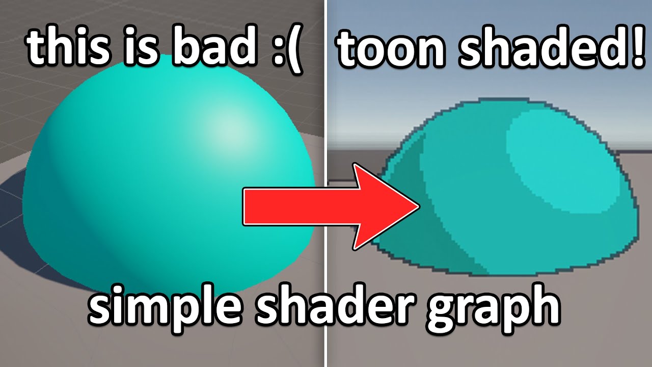
Hi, I'm stealing the "Lazy Tutorial" naming from the great Ian Hubert. This is not a proper tutorial, more of a rundown of how I achieved this effect.
#indiegame #gamedev #unity
Please consider supporting me by following me over at https://twitch.tv/whateep
Custom Function node HLSL code:
#if SHADERGRAPH_PREVIEW
Direction = half3(0.5, 0.5...
i followed the tutorial, now i am just left wondering what i need to do to actually see the shader in my scene...
into base color^
Does anyone know how to make it so I can get a glowing effect on individual objects? I've tried to follow like 50 different tutorials the last few days and I can't seem to get anything to work at all and I can't understand why or what I'm doing wrong. This is for 2D, I've tried post processing volume, using a shader graph, one of the tutorials said to make a material and check the emission box but when I create a material there isn't any emission box at all. I know about global volume but I don't want it to affect everything on screen and I'm just completely lost as to why it works in 2 minutes in the tutorials I watch but when I follow them step by step it just doesn't
Do you know of any Mac alternatives to shader map 4? I don't have a PC.
Heya! I wanna make a shader that basically flattens any 3d mesh based on the direction of the camera to get a doom-enemy-esque effect but I'm having trouble when it comes to making the flatness follow the camera around.
Basically, I want you to not be able to tell that the enemy you're fighting is flat until you go above them in any way, where you can now see that it is, indeed, thin as a piece of paper.
Thus far I've made whats shown in the screenshot, with the "FlattenVector" value being equivalent to the right vector of the model.
If I set "FlattenVector" to (1,0,0), or (0,0,1) then the mesh looks perfectly flat as I want it to (as seen on the first gif), but as soon as I set it to a diagonal vector, like (0.5, 0, 0.5) it stops being flat.
Is there any way to make it so that its possibleto flatten characters from diagonal angles? Thanks in advance!


Hi there! Not a super robust answer but I'd recommend looking into point plane projection. You can use the dot product to calculate the distance to the camera plane and then add that distance in the direction to the plane to flatten it. https://stackoverflow.com/a/9605695

Stack Overflow
I have a 3D point (point_x,point_y,point_z) and I want to project it onto a 2D plane in 3D space which (the plane) is defined by a point coordinates (orig_x,orig_y,orig_z) and a unary perpendicular
how can I tile my shader with x y z ? with tilling im locked with only vector 2
You dont have a Z when tiling. Tiling just tiles the 2D Texture in X and Y
you can control Z tiling, use the Y as the Z
my issue is that it seems that I can't "combine" two tiling so all axis are tiled correctly

Exactly where?😅


Are you using a render pipeline compatible with the shader output ?
sorry i am very new to the whole world of shaders.... I am using the URP Shader Graph
What targets do you have here ? (top right corner of SG window)


And are you in a project that is using the Universal Render Pipeline ?
I am fairly sure i am. is there a way to confirm that i am? :))) (thanks for the help)
Check the project settings :

(I'm in a HDRP project for my screenshots, but it's the same for URP)
Or, it can be in the Quality settings, the current active quality level can have a dedicated URP asset

Well, looks like you do have URP imported in your project, but not set up
If the grass material that I see in you screenshot uses the "Standard" shader, you are actually using the built-in renderer
So, you have two choices here : swith you project to URP, or switch your shader to target built-in
okay so i switched active targets in the target settings to "Built-In" and now i get the following errors

Ok, I didn't have the full context of you shader. So you are trying to make a custom lighting (toon) shader ?
I guess you have some custom lighting nodes in there, and they do not support the built-in renderer
aha, yes you are correct. I am guessing that the custom lighting node is this one:

I guess that the only choice left to you is to setup URP in your project : https://docs.unity3d.com/Packages/com.unity.render-pipelines.universal@14.0/manual/InstallURPIntoAProject.html
okay im pretty sure i did everything correctly, however, now everything in my project is pink

and the shader graph looks like this
Having converted the project, previous materials using the standard shader no longer work with URP and need to be converted, look at the "Upgrading your Shaders" section
But the cube with this shader assigned is still pink ?
hey guys how would you go in making a Sun like background/shader that moves like the 80's games? https://www.youtube.com/watch?v=YIT03mDqX5Y&t=1463s like this

Played by: xRavenXP
Axelay is a shoot 'em up released by Konami for the Super Nintendo in 1992 in Japan and 1993 in Europe and USA. Considered one of the best games in the genre Axelay was one of the first games to use the technique Mode 7.
Before each stage, you can choose 3 weapons to equip your ship a normal shot, ...
Scrolling texture + UV distortion
Hey! 😄
I have this sprite in my 3D project, I want to make it so it's visible no matter what's in front of it
I tried a bunch of shaders I found online, they work great with regular 3d objects but when I apply it to my sprite they won't work.
I've been trying to figure this out all day, but sadly to no avail.
Any ideas what I could do? I'm completely lost.

hmmm nice ideea

the cube is the only thing that is not pink
Problem solved. XD
Yep, so this "expected" : the cube uses a URP compatible shader and shows like intended, and you need to fix the material of the grass plane
What render pipeline are you using ?

i have applied the shader material to everything now, and it now looks like this:

I guess you shader is outputing full white 😅
i am a shader idiot
Yes kind of. It mean you are using the built-in renderer
Hum, iirc sprites when used in 3D scenes are just flat meshes, so any regular material should work with it.
You don't need a specific shader, if you use the standard shader for example you should be able to change it's render queue to "after transparent" or something so it is rendered after everything else.
😓 Sorry for being a total newbie, but how would I do that?
Is that an option in the mat settings?


I'm getting this error, am I missing something?
This is a new standard material I just created in my assets folder, I tried selecting transparent then the error occured
Ah, yes, I forgot this was added and doesn't allow to set any value you want anymore :/
You could set the Rendering mode to "Transparent", that should allow to increase the Queue value up to 3999

Hum, I was suspecting this :/
IDK what are the other shaders you have doing, but to make this work they need to :
- Render after everything else : have a high render queue
- No depth test : Z-Test Off
You should be able to spot this in their code


I was able to get this to work
😂 but the color now looks abysmal, any ideas how I could fix this?
Hang on, let me share the code
    Properties {
        _Color ("Main Color", Color) = (1,1,1,1)
        _MainTex ("Base (RGB)", 2D) = "white" {}
        _OccludeColor ("Occlusion Color", Color) = (0,0,1,1)
    }
    SubShader {
        Tags {"Queue"="Geometry+5"}
        // occluded pass
        Pass {
            ZWrite Off
            Blend One Zero
            ZTest Greater
            Color [_OccludeColor]
        }
        // Vertex lights
        Pass {
            Tags {"LightMode" = "Vertex"}
            ZWrite On
            Lighting On
            SeparateSpecular On
            Material {
                Diffuse [_Color]
                Ambient [_Color]
                // Emission [_PPLAmbient]
            }
            SetTexture [_MainTex] {
                ConstantColor [_Color]
                Combine texture * primary DOUBLE, texture * constant
            }
        }
    }
    FallBack "Diffuse", 1
}
Which one of the screenshots it looking good for you ? the blue or purple one ?
The blue is supposed to be blue, although I would prefer it to retain the original color while still being 'see through', this is just a random shader I found online
The real issue is that the original sprite I had was 255,0,255 (pink) and now it's very dark and the colors are messed up
I went from this

To this

That shader is applying lighing to the image, that's probably why it gets darker.
So, you want it to have a constant unlit look, and never be masked, am I right ?
My final goal is for it to retain it's sexy pink look, even if it's obscured by something
The shader I provided was the only one that was working, I found it online, I actually have no need for it to be blue when it's obscured by something
I fixed the lighting

Now I just want to get rid of the functionality where it is blue when its occluded
Also from behind it is invisible, I'm trying to wrap my head around why this happens
@amber saffron thanks! you are so cool

Try this shader :
Shader "Unlit/AlwaysDisplay"
{
    Properties
    {
        _MainTex ("Texture", 2D) = "white" {}
    }
    SubShader
    {
        Tags { "RenderType"="Overlay" "Queue"="Overlay"}
        LOD 100

        Pass
        {
            Blend SrcAlpha OneMinusSrcAlpha
            ZTest Always
            ZWrite Off
            Cull Off

            CGPROGRAM
            #pragma vertex vert
            #pragma fragment frag

            #include "UnityCG.cginc"

            struct appdata
            {
                float4 vertex : POSITION;
                float2 uv : TEXCOORD0;
            };

            struct v2f
            {
                float2 uv : TEXCOORD0;
                float4 vertex : SV_POSITION;
            };

            sampler2D _MainTex;
            float4 _MainTex_ST;

            v2f vert (appdata v)
            {
                v2f o;
                o.vertex = UnityObjectToClipPos(v.vertex);
                o.uv = TRANSFORM_TEX(v.uv, _MainTex);
                return o;
            }

            fixed4 frag (v2f i) : SV_Target
            {
                // sample the texture
                fixed4 col = tex2D(_MainTex, i.uv);
                return col;
            }
            ENDCG
        }
    }
}
It's working, thank you so much! ❤️
@amber saffron would you know where this little point here comes from? :

Could you post a screenshot of you graph where nodes are readable ? 🙂


nvm, i found out, it is from the compression on the texture image i used for the Shading Ramp
Maybe not compression, I think the image was just wrapping instead of clamping ?
remy, now the big question is, is there a way to use this shader, and have different colors and materials on in game objects?
The shader/materials workflow is this : a shader is the code executed by the GPU, and materials bind properties with a shader.
So, you can have multiples materials, using the same shader, with different properties.
To use this single shader, on multiple object with different colors, create as many materials as you need, assign them the shader, tweak the colors and assign those materials to the objects.
Note that unity recently introduced the concept of "Material Variants", it is basically how prefabs & nested prefabs work, but with materials.
You can create a "Master" material from you shader, that holds the base color and ramp/fresnel settings, and then create variants for all the objects in the scene, only overriding the color.
That way, you will have a consistant ramp/fresnel look in your scene, and you can tweak it in a single place.

multiply it by a color
3 materials, one different colors set per material
@sterile rain You'll need to expose colors properties on the shadergraph to be able to edit it on the material level
So you replace those two constant color nodes by the properties :

!code

Posting code
📃 Large Code Blocks
Use links to services like:
https://gdl.space/, https://paste.ofcode.org/, https://hatebin.com/, https://paste.myst.rs/, https://hastebin.com/
📃 Inline Code
Surround code with three backquotes. Not quotation marks.
To format as C#, add cs to the first line:
```cs
// Your code here
```
Add a comment with a line number if there is an error message.
https://gdl.space/ibolulekad.cs This shader script makes objects come out with a toony style, and a toony outline. however the lighting only works from a single directional light, and any aditional lights do not affect the shader. Say i wanted to make a torch that would effect the area around it, how would i edit this shader to make that work
these 2 objects have the exact same material, why is the diamond showing up as a blur while the square has the correct display effect

this only happens when the game is built and ran
Are you changing something on the diamond material at runtime ?
If you are changing a keyword on the material, you must be sur that the shader with the matching keyword variants is available in the build.
Ususally it is prefered to swap the material to one with the wanted setting that has been referenced in the script, that way Unity automatically generates the required variants based on the scene dependencies.
i get that but the value that is being changed is a float to control how much of the object should be transparent
so i cant really swap materials to create the dissolving effect
Only the float is changing ? Then indeed there shouldn't be a variant issue 🤔
Maybe check that the float is actually changing in the build and is not stock to it's initial value ?
How would I check in the build?
You can use OnGUI to display stuff on screen, or Debug.Log and enable development build to display the console in game
Okay okay thanks
found the issue nvm
the diamond just isnt displaying the material properly
im struggling to find out why this is only happening in the build though
Log as much informations as you can in the build to identify what could be happening : the material name, shader name, the float property value .. anything you can think of that could be the issue.
The other solution to try to understand is to use a tool like RenderDoc to inspect the rendering of the object.
Also, is the diamon in the scene already using the shader or do you maybe swap the shader at runtime ?
hey guys. is there a way to "apply" triplanar shader to a mesh so the texture stays the same wherever i move the mesh?
yes, triplanar node inside of the shader graph is as simple as it comes
yeah i have the triplanar shader. but my problem is that i want it to work like its baked onto a mesh. so when i move the mesh it doesnt look weird. is there a way to apply the triplanar texture in that way?
Use object space position instead of world!
It won't help you make multiple neighboring meshes look like they're all one material - that's the only catch.
But if you're just trying to do quick texturing that will work
On ShaderGraph, how would you make 'Camera' an assignable camera rather than always taking the CameraMain?
(and if that's not possible, how can I make an assignable variable on the shadergraph that can output a gameobject's Position and Direction? because on the blackboard, i see no option to add a 'Camera' or 'GameObject' variable)

you can send in a vector3 of coordinates (or matrix) probably
I wonder why the node doesn't give rotation but position and direction
Set up properties in the blackboard, and set them from a C# script using the SetVector/Matrix/Float/etc functions on the material, https://docs.unity3d.com/ScriptReference/Material.html
Or the similar SetGlobalX functions in the Shader class for unexposed properties, to use the same value for all materials
Probably as it's more common to use matrices than having euler/quaternion rotations in shaders. e.g. would use the Transform node to convert to camera/view space
Would anyone know why literally just this single Node in a shadergraph causes my Plane to visually become bigger when i apply the material to it?

and i guess to add to this question, how can I have this shadergraph not cause the plane to get bigger when i apply it?

yep! the reason is that position node takes a local position instead of a world position
click on the dropdown "space"
and set it to object
if you need world you can always transform it back at the end
If I want to make a shader that affects the whole screen, how could I do that with shader graph? I want to create outlines and posterization.
Would I make a fullscreen shader?

phew! thank you
It looks like you're HDRP -- you'll create one of those fullscreen shaders then apply it as a custom post process: https://docs.unity3d.com/Packages/com.unity.render-pipelines.high-definition@17.0/manual/custom-post-processing-create-apply.html
Posterization will be easier than outlines
since outlines you need multiple samples for
which can be kind of overwhelming in shadergraph
but totally doable
especially for outlines which only need a handful and not a loops worth
like some blurs
//Script
https://hatebin.com/woievujela
//Image
https://i.imgur.com/63G9QzQ.png
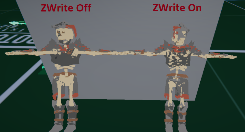
So I've been using one of bgolus scripts for a lot of my 2D objects in my 3D world and it works great beyond breaking some batching. Now, I've had some ideas on another project where I would like that top down view with some tilt on some 3D characters so I can actually see their fronts a bit more.
Unfortunately, the shader doesn't work as expected considering that I do need ZWrite on for these complex character meshes otherwise I run into issues where pieces of the character would render over another incorrectly. I've tried experimenting with clip space with other than the z, but even though I understand the operations happening, the logic of how this all works still goes very far over my head.
So some ideas I have at this point: ditch the shader, lock the camera, change pivots of all 3D renders and sort by -zy. That's more of a last case scenario, but ideally if I could figure out a way to tackle this shader further I'd probably want to manipulate their coordinates but in 2D screenspace(?) or however I can go about applying this shader to this object after the object has sorted its own depth out.
Unity Forum
Hey guys, I've been experimenting with building a tactics engine using 3D geometry but 2D character sprites, similar to the Final Fantasy Tactics and...

So should I figure out how to do posterization first? This is my second time using shader graph, the first time I made a toon water shader.
I think that would be a really good shader to start learning with
I've seen problems like this also solved using SV_Depth but only for 2D sprites in 3D environments.
and I think in that situation if you had a 3d model you'd still want the depth to all be set to the one plane so you'd get the smushing.
Yeah, exactly. Would that be done in a single pass you think?
Yeah that's a single pass approach but I think it also breaks batching.
Probably fine? Two passes probably creates similar problems, but I'd go with the easiest solutions honestly.
But yeah, how I'm thinking it is I need to squash it back into that quad format, then I can valuate it in clip space on those specific verts
OKOKOK
what if you squished it but just a little bit
just enough that it tilts properly
and doesn't intersect
but still extrudes a bit also - enough that the zfighting goes away
Currently I have an issue where unity is throwing this error.


I guess that's what you're pitching with the pivots idea
sort of
at some point i think the depth can't all be the same if they're zwriting
Right, well the two cases here is with ZWrite off then we've verts that are having problems sorting with each other on the same model which is what happens if you use a transparent detailed mesh without ZWrite On. With ZWrite off I do get the depth sort on the model itself, but I'm not entirely sure how it's being evaluated, but there does seem to be some z-fighting?
the defaults of the script do have ZWrite off, so apparently the sorting of it all is less relevant as I guess the clipping handles it all.
I should actually try it with a quad with ZWrite on and see if I get any z-fighting and whatnot
sounds good! one other extreme approach would be to render them into rendertextures but you wouldn't be able to do that many and rendertextures can be really slow on some platforms.
im pretty confident this can be solved w/o that
that's a strange one! is everything else working okay? are you able to open it ?
is that error coming up related to the post processing or something else ?
https://i.imgur.com/FTTOEj0.png
Seems fine with or without writing to depth for 2D. Magic I tell ya.
I can open the shader fine, currently what ive done is create a shader graph, then made a custom post processing volume. Gave them the same name, then I added this to the graph.

oh! you probably wont be using a texturearray named maintex for a postprocess
since that's where the color comes in from the scene
but that doesn't seem to be your problem
that is nuts i wish i knew about that script when i was working w/ the custom depth lol
its a headache
Here is the whole error

The custom post process volume
yes ok cool
I understand what's going on
Posterization is going to be under
Shadergraph/Posterization
hidden/youreffect is where it would be if you made it in text
by default
you can check the path of the shader by making a new material
The error is gone now :D
sweet : )
but now I am lost on how to get the rendered image for the shader and apply the effect to it.
i j set this up on my end im messing around a little to see what happens
I'd give you my nice 2D version but half of it is me debugging stuff and it looks terrible lmao
sprite shaders in URP require a lot of extra fiddling because they use basetex or w/e instead of _MainTex
probably better off just skipping out on spriterender anyway since it breaks batching
you need to add it in your hdrp global settings: https://docs.unity3d.com/Packages/com.unity.render-pipelines.high-definition@17.0/manual/custom-post-processing-create-apply.html
I already applied it
Do I not need to access the render texture or something to apply the posterization to it?
OH This is for a rendertexture?
I don't know
if its a fullscreen post process we've gotta go through all of these steps but if its a rendertexture its a little simpler
I want to make the game screen have a posterization effect. wouldnt I need to get a reference to the screen?
yep so the way that usually works is it assigns the color of the image to _MainTex
but the naming might be different for HDRP
I'll check
yeah -- based on the docs it's expecting a Texture2D to assign to called "_MainTex"
make sure you have one of those in your blackboard
and that's what you should sample to get your color
you dont need to put anything in there
it will automatically be filled in by the post process
I made a test scene and I'm starting to understand what you're saying a bit better about having to sort things! I forget what the effect is called. It's like a vertex sorting problem.
It's not the same as Z fighting its related to the way the indices are ordered.
very frustrating
problem
im liking your idea more and more of going with multiple passes
For some reason its throwing this error

hm - i actually dont know about that one
is it blocking you?
one of the pieces of the documentation says that you need to set the shader to always loaded
Actually is that doable with SRP? I remember reading this was more of a built-in feature or maybe that was another feature

I did that, but I am still getting the error?

tbh im not sure why that's happening. it might be unity issue if you've followed the documentation to a tee.
is it stopping you from entering playmode?
no
but I have the shader intensity at 0 rn because the shader is pure gray.
nvm
its working fine i guess
oh nice!


It works now :D
I know I need to separate the value to lower the smoothness of it, but I dont know how to lower the smoothness of it.
ok so -- multi pass shader no -- multiple materials attached to one object -- yes
ill probably have to read more into the pipeline. Been a while and there seems to be a lot more as of recent so might as well get acquainted with it all.
but as far as solving the issue as is, even by experimenting I wasn't getting any results and I doubt I'll be understanding the logic any time soon
ahh gotcha!
cool shader for when you don't some billboards clipping into your world
very cool
it's just unfortunate that it breaks batching (which is another feature I'm not entirely sure how unity has it working)
yeah I thought URP had its own batcher that was really flexible
spriterender is still in the past is the issue I think
OH I understand its not just that
it doesn't work with batching because it needs a model matrix that isn't batched together with something else to billboard
i dont know if that's a problem for URP batching though
my understanding as far as batching goes is it glues everything together into one mesh or something to reduce it to smaller draw calls every update
right -- in the process it can mess w/ your model matrix too
so sometimes you'll write an object space shader
that looks different in batching
and i think this one is very sensitive to that
i think that wisdom applied with the old built in pipeline batching but not sure if it applies to URP anymore
ah, ok I think I may understand if it has to do with cacheing
the reason being that multiple objects can share a model matrix when combined and object space changes
static batching is pretty simple concept, object don't move then cache it and forget about it
spriterender forces dynamic batching no matter what, even if it may seem static
which is why it may just be better to use quads
oh i understand what you're saying
still, stuff to profile but I can assure you that the srp batcher pretty good cause it beats my voxel batcher no matter what lmao
I found something that limits the values between two edges, but it doesnt make steps of them, it just prevents values from being greater than or less than the 2 edge values I define.
what function is that ?
Base Image 1st. after smoothstep 2nd.


yes
sometimes its helpful for me to try things out in graphtoy to see the shapes of different math functions https://graphtoy.com/
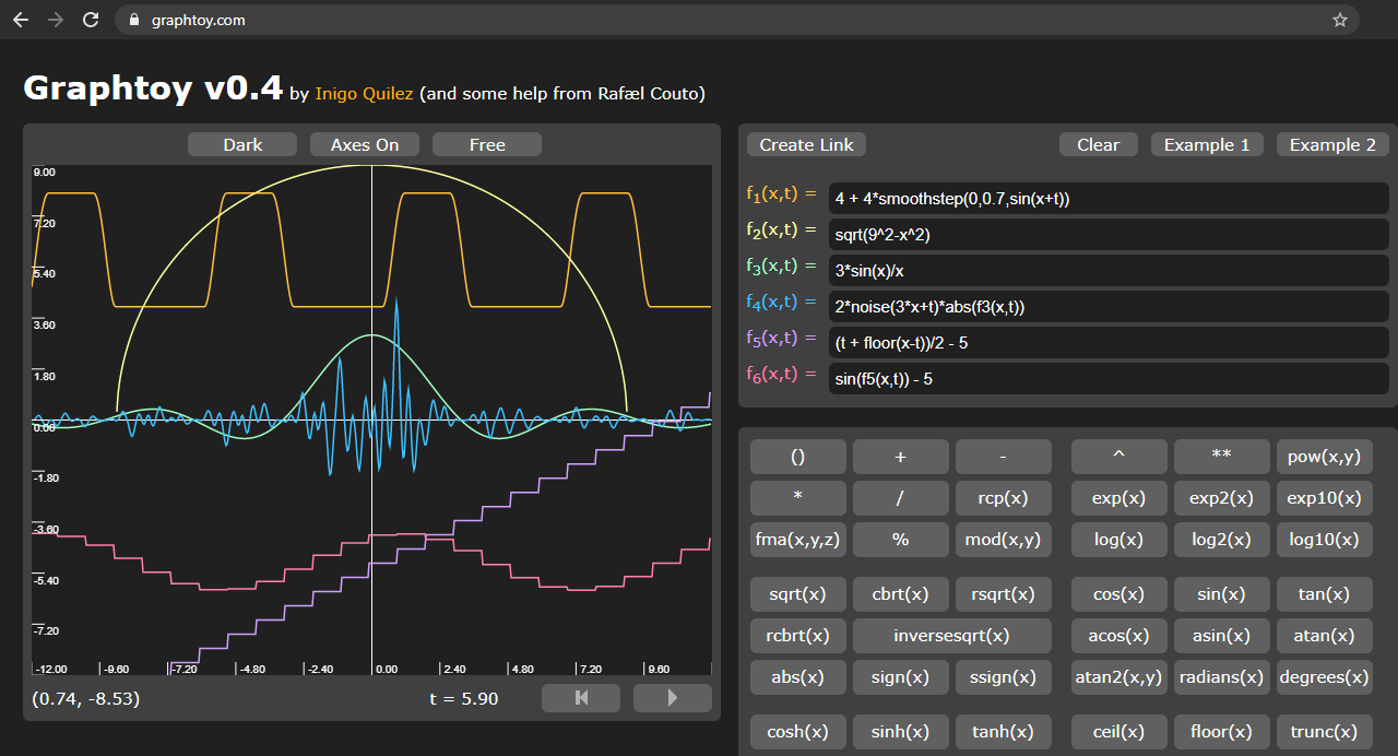
Graphing functions easily on the web
I'd recommend using something like round, floor, or ceil
to get a stepping effect
one pattern you can use is round(value * numSteps) / numSteps
which might give you something like what you're looking for


here you can see in graphtoy it keeps the values in the range from 0-1 but adds more steps
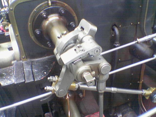
I took what you showed me and applied it to the shader and this is how it looks rn.


It worked well on the sky, but it has this weird thing by the axe
you mean around the handle ?
im not sure what that is -- it is a little strange
maybe its bloom related ?
Its not bloom related, I dont have any bloom. Its being very sharp at some parts for some reason.

The sky looks really cool

Well, now that the posterization is working, how can I go about creating outlines?
if i were going to do an outline with HDRP I'd try to do it from the depth buffer
and sample in a grid in depth
checking to see if there's any big changes in depth
where are you thinking you'd want the lines?
the catch with this approach is it would only give you very thin outlines
sobel operator is the basic idea https://en.wikipedia.org/wiki/Sobel_operator
The Sobel operator, sometimes called the Sobel–Feldman operator or Sobel filter, is used in image processing and computer vision, particularly within edge detection algorithms where it creates an image emphasising edges. It is named after Irwin Sobel and Gary M. Feldman, colleagues at the Stanford Artificial Intelligence Laboratory (SAIL). Sobel...
How would I do that?
wait rly quick what outlines are you trying to get
are you trying to outline characters?
or outline contours in your posterization ?
I am making a horror game, and I am in LOVE with lethal company graphics.
I really want similar outlines to that
ooooooo gotcha one sec lemme watch some footage
np
Based on the footage I can't tell if its post processed or just an inverted shell outline
I kinda think its a mix of inverted shell outline and then materials
rather than full screen post processes
just because its effected by blur sometimes
outlines can get really technical:
https://github.com/alelievr/HDRP-Custom-Passes
GitHub
A bunch of custom passes made for HDRP. Contribute to alelievr/HDRP-Custom-Passes development by creating an account on GitHub.
part of the reason this is taking me a sec is because I'm trying to think of a way to do this without throwing you too far out there since it seems like you're still getting familiar with shaders
but if you're comfortable exploring a bit this repo has some great examples that you might be able to modify to your liking to learn from
I tend to go here when I'm trying to figure out custom passes for HDRP
the basic idea I think I would try to keep in my mind while doing outlines is this pattern of edge detection:
sample up
sample down
sample left
sample right
was any sample very different from the others?
if so its probably an edge
and you can sample textures that way
or continuous functions like noise
there are more advanced ways of pulling all of that stuff out too
the easiest way to make outlines is to use the inverted hull method
which has some gotchas
Watch this video https://www.youtube.com/watch?v=Z_-am00EXIc. Goes into every detail on how its done

The first 500 people to use my link will get a 1 month free trial of Skillshare: https://skl.sh/acerola01241 ! #ad
Lethal Company has some very compelling visuals, but how much of it did the developer make themselves? And how does it all come together?
Topics covered: Frame capturing, fixed resolution rendering, edge detection, posterization, ...
oh awesome!!
It uses HDRP and shader graph just like I'm doing
are there specific parts of this you're having trouble w/?
there it is!!

thank u acerola haha
that's basically what i was just summing up above
I love that guy!!
you just need to figure out what to find the max local contrast of
in a lot of cases its the depth
i've gotta dip for the night unfortunately
so i can't help too much deeper but you've got some good tools to mess with!! hopefully someone else can pick up
oh cool actually this is more straighforward than I thought -- its checking the difference in normals between pixels
so you need to figure out how to get the normals into your post process material
and then use a sobel operator to detect the edge
and then color that edge
Thank you so much for helping me with this, all of this info will help immensely.
sampling depth can be a little challenging but it looks like you might have luck if you try this node: https://docs.unity3d.com/Packages/com.unity.shadergraph@6.9/manual/Scene-Depth-Node.html
it grabs the camera depth texture
which at the step that you're grabbing the color should still line up
depth buffers are more complicated than color textures so it'll take some fiddling
oops sorry that's depth not normals
you'll have to figure out the normals part!! gotta dip hopefully someone else knows the answer
good luck!!
thank you!!
Hey just so you know in the morning, I couldnt figure it out, I cant seem to find how to apply Sobel edge detection via shader graph. As with lethal company the developer applied two outlines, one, a depth difference edge detector, and two, either a color difference or a normal difference edge detector.
This is sobel

This extra detailed stuff is either color difference or normals.

I'm gonna go to bed now.
https://gdl.space/ibolulekad.cs This shader script makes objects come out with a toony style, and a toony outline. however the lighting only works from a single directional light, and any aditional lights do not affect the shader. Say i wanted to make a torch that would effect the area around it, how would i edit this shader to make that work
hi i dont know much about shader editors but i just found about Amplify. can a shader created in amplify be easily recreated without it?
Hey guys, i have hardly any experience with shaders in gamedev, just a bit of HLSL, so my question may sound stupid.
I use hdrp, and often only have a roughnessmap texture for the metallic/specular shader workflow.
Let's say i just want the main/default specular shader with a small change, i want it to invert the roughnessmap so i can use it directly as specularmap, or any other small change... How do I do this? When I choose -> Create -> Shader -> Surface Shader this is basically a light version without bumpmap. Not what I want (as base). I tried to explain to chat gpt what I want but it didn't get my question. Whelp ^^
For hdrp you need to use shadergraph. As of now it is the preferred way of making custom hdrp shaders
How ever I would suggest to simply convert your maps offline. No need to waste the instructions in a shader
I'm a damn lazy mf but you're probably right. Thanks for the shader graph direction. I don't like visual scripting though heh
Hi I spent some time this morning mocking up edge detection in shadergraph for you! I haven't implemented a full sobel operator nor integrated it w/ the normals but I tried to make it as clean as I could so you could try to plug those in to learn yourself. Anything involving multiple textures samples is gonna be a mess in nodes.
I also came across this node which might be helpful for you:
https://docs.unity.cn/Packages/com.unity.shadergraph@16.0/manual/HD-Sample-Buffer-Node.html

Overall the shader is very simple -- it just looks crazy because everything needs to be done 9 times lol.
here's the filter on windows bliss

Hey, in my scene veiw my game looks fine, but when I open in VR, in game view half my map is missing/invisible
im not even sure how to debug this
its more a setup issue/camera issue/vr issue/xr plugin issue i think
Anyone know how to go about debugging this? Its not clipping plane, its not render distance
No errors in the console
Thank you for the shader, I was looking on how I could implement it into my posterization shader, but when I imported the shadergraph it throws me this error.
Maybe something weird with the occlusion culling?
It hides everything that’s not seen by the camera
Will check on that one
I did way too many things at once, so idk what messed it up.
But i upgraded my oculus SDK, upgraded unity version, and changed some render settings (although I think I changed them all back with git diff)
I was going to move some of the graph to my shader to see how it works, but it doesnt look like I can convert Texture2DArray to Texture2D
my graph uses Texture2DArray because it throws the same error if I don't.
Sounds like many changed at once
classic mistake
anyways, I can roll back if i need to
trying to debug it first


so if i toggle mesh renderer off and on, itll render fine
but on init, it doesn't show up
🤔
and then when I deselect it, it will disapear again
Hmm, sadly I have no clue what causes this. VR is magic sometimes 😂
im not even in VR. This is just the main camera. It may be affected by the vr setup tho yeah
oh maybe if I make a new camera it will help me debug
ok I finally circled back to occulsion culling
apparently that was it 😄
thanks my guy
Ohhh, I moved my game objects around and didn't bake the occulusion culling
^ thx man
Is there a reason you're using array instead of texture2d?
🤓 Nice
I get the same error if I dont use Texture2DArray
Then it doesnt render
You probably need to get rid of the texture2dArray node in the graph and replace it with a texture2d
If I use Texture2D I get an error saying that unity is trying to assign a Texture2DArray to a Texture2D
Oh interesting hm
which means for some reason unity is using a texture2darray instead of texture2d
I didn't realize HDRP used those for post processes that's pretty weird
anyway you can fix the issue by changing those nodes to sample texture2dArray instead
instead of sampletexture2d
Texture Size node doesnt work with texture2darray
I cant make this work with texture2darray

It doesnt let me connect them
because TextureSize wants a texture, and there isnt a TextureArraySize node
you might need to pass that information in the pass -- there's a way to get it from the shader but it might be a little more complex for texturearraysize
and require custom hlsl
I'd recommend going up a level
to the C#
and setting it in the material
so where it says
m_Material.SetTexture("_MainTex", source);
& m_Material.SetFloat("_Intensity", intensity.value);
make a new couple that are
m_Material.SetFloat("_Width", texture.width); etc
Where would I get the texture variable?
it's called source in the C# function
and its an RTHandle
so you'll have to read up a little on those
Like this? m_Material.SetFloat("_Width", source.scaleFactor.x);
lmfao too much documentation
or is scaleFactor a value between 0 and 1?
does it let you grab the rendertexture underneath?
that's what I would try first
source.rt.width
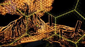
I converted it, here is with and without the shader.


lets goooo!!!!!
hell yeah : )
from there if you wanted to put that outline over something the rest is pretty simple
oh?
what would be the T factor?

Um, well I tried setting it too lerp at 0.5, perfectly inbetween, and this is how it looks.

closer
much closer than yesterday
Woah, even closer!

I did it :D

Black outlines :)
and I can change the color of the outlines by changing the value of B
How can I lower the threshold of the outline?
wooh!!
Hmm, it appears to be outlining based on color, which is good for the detaily bits

yep - that makes sense because right now you're just outlining color
you can take what you have and switch it pretty easily to normals once you figure out which texture has them in it
So its outlining based on when there is a large contrast in color
: )
for sure! keep messing around w/ it

whoa
i actually dont know
i haven't tested it as a post process
it might have something to do w/ the width variable ?
That was actually happening before I applied your outlining to it.
It would just happen sometimes when I stopped the game.
does your console tell you anything?
no, sometimes I can only see a quarter of the screen, sometimes there is just a black bar at the top.

nope, no errors. Its really weird.
did it start happening when you added the pass ?
& does it go away when you remove it ?
Let me check rq
Yeah, it goes away when I disable the pass.
It looks like its trying to make the visible area in viewport the same size as the game window, for some reason.
Weird --
A couple of things to look at:
Order of operations, when does the post process get called?
The texture its pulling from -- maybe the width and height is improperly set
You could try sampling scene color in a different way
Any recommendations on toon shader tutorials / cel-shading? Looking for something a little more structured than usual.
this node looks promising -- i think its mostly for objects and not post processes but its worth a shot
I assume toon shader means cel-shaded or is my terminology off
I feel like they're pretty interchangable!! The other thing I see thrown around a lot is Non Photorealistic Rendering (NPR)
I feel like they're diff levels of specificity
Non Photorealistic Rendering <- Toon Shader <- Cel Shading
https://www.youtube.com/watch?v=YIT03mDqX5Y&t=1463s Hey guys I would need some help with making the background/skybox or something similar like this. How would ya do it?
Played by: xRavenXP
Axelay is a shoot 'em up released by Konami for the Super Nintendo in 1992 in Japan and 1993 in Europe and USA. Considered one of the best games in the genre Axelay was one of the first games to use the technique Mode 7.
Before each stage, you can choose 3 weapons to equip your ship a normal shot, ...
maybe a better term is over-saturated shaders and neat shadowing and outlining with specular reflections
I don't know any off the top of my head so I wanna leave space for a sec for someone else to respond. I can think of a lot of nice outlining tutorials but less for cel shading.
but I know its a really fleshed out area

Reddit
Explore this post and more from the Unity3D community
going for something like that
which is a followup to my previous shader problem
wow this rocks
fair enough!! how did you handle it on the cpu ?
I remember a lot of people were changing the way they handled cel shading after Dragon Ball Z Fighters came out
instead of just making a fancy shader and trying to solve everything in code people started bending normals
and I feel like its been like -- leaps and bounds since then
and it's basically like billboarding
so this probably still has characters leaning into the wall right?
I think that's where I got stuck before
but this feels like a really elegant solution
I think that's why people put so much work into the z-depth thing
the shader would be nice for the sorting, but maybe I'll just figure a way to pivot shift stuff into view
if you wanted tilt shifting, you do it like 2D top down and put the pivots lower
but in 3D that requires probably blender to rearrrange it all
and lock the camera
or do it the nintendo way and make all assets tilted by 35 degrees
no way

this rocks haha
I know a lot of league of legends characters are modeled to be looked at from above too
right, that's the problem with top-down. You can never see the character fully
you can get away with isometric, but you wouldn't allow camera rotation in that perspective, or from what I've been experimenting with
too jarring
this looks awesome -- I'll bet you could do this just with a rendertexture on a mesh. Render the background to a texture and then apply it to a cylinder shape facing the camera.
that makes a lot of sense
wow people have gone so hard on cel shaders
I think a lot of them are for VRChat
https://hatebin.com/qwpscrfiqo
Actually this is the cpu version, the other was billboarding with shader with secondary cpu rotation
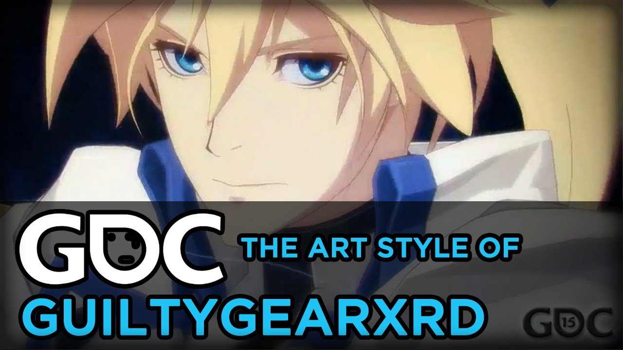
While the quality of photo-realistic real-time graphics in games is advancing daily to near feature-film quality, Arc System Works' RED team took a completely different approach with Guilty Gear Xrd in pursuit of an impressive art style that would stand out even in this competitive environment. The team's mission was to rebuild a classic 2D figh...
here's the talk I was thinking of
something like that. Still need a nice 2D/toon shader to really compare
it's not a specific tutorial but breaks down their whole workflow
yeah guilty gear is pretty redic

not just the art fools you but the animation is a big part
as it blends in like a frame-by-frame instead of smooth transition to give you the illusion of 2D
kinda the idea of this shader, but more for camera rotating than the animation
So it would snap at different angles like the one in the video you posted?
yeah, similar to 2D sprite games in a 3D world. There's usually like 8 different sprite orientations
The other game I'm thinking of that does a lot of this is Prodeus.
It's a boomer shooter aesthetic too.
if you're looking for diff kinds of reference
always. I was just going to stick to the sprite idea, but easier to animate in 3D
and model for that matter
I keep trying to find this article I found a while back where they had a bunch of these sprites for mobile
that they rendered in 3d offscreen
into a render texture
then cleverly chopped up
and placed in the scene on planes
right, that's what dead cels does
oh cool!

"To make up for the lack of bandwidth and still deliver on quality, we had to find a pipeline that could give us great looking pixel art, without having to hand draw each and every retake," writes Dead Cells artist Thomas Vasseur.
is it performnce reasons keeping you from approaching it that way ?
that's my target right there, but keeping it in 3D world space
2D sprites in 3D world beyond the amount of work you need to get it to look good, just requires more work as 2D is much more demanding than 3D
drawing frame by frame is lunacy unless you're doing that "retro" pixel look
anyway gtg laters
ttyl!
how can i make my shader not affected by scale ?
Hi -- what does your shader do?
and what part of it is being negatively affected by scale ?
I usually use Object > Scale > Tiling and Offset
but it doesnt allow me to tile x y z
it just some colors
are you using shadergraph?
but its a patern so you can see its scaling and tiling weirdly
yes
well when using UV in the voronoi
i can only scale in 2 directions, i tried aother stuff but it didnt work


oh sorry I misunderstood
could you use world space UV coordinates instead of object space?
if I understand correctly you want to set it up so that when you scale the object the texture doesn't appear to scale with it
I'd give triplanar mapping a shot first and see if that solves your problem
anyone has a shader that outlines objects? as if they are selected or something
The extra detail outline is working well, however, to recreate lethal company graphics, I would need two edge detectors. One, the detailed color difference one, and another based on difference in depth.
Because while I have an outline here because of color difference.

I dont have one here because the colors are too similar

I think the normals are also really important to that look. They might even cover a lot of what you're looking for.
I can't seem to find anything to access the normals.
Using just the Normal Vector node looks like this

I was poking around and it looks like there are also samples you could look at under HDRP Sample Content for the latest version: https://docs.unity3d.com/Packages/com.unity.render-pipelines.high-definition@17.0/manual/HDRP-Sample-Content.html
There's a sobel operator in there that's a bit more fleshed out than mine -- it might not be shadergraph but its worth studying just to see how they're doing it.
It has an edge detection shadergraph, using Robert Cross Sampling
Its a bit complicated though

Its also really messy to look at
yeah those things really dont lend well to nodes
I've never used robert's cross sampling im pretty curious
looks really nice

awesome
(this is a bark material)
That seems consistentent with the lethal company details
So I could use the way they got the normals for mine
yep!
Hey Remy, so i made the colors into nodes that i can now change in the material level, but when i change the color, all of the shapes with the material on them changes colors..:

is there some way to make it change these values "locally"? or would i have to do something else?
Wowzers!

or would i have to make a new material for every color that i want to use?
a couple ways i can think of:
- use vertex colors in the mesh - that's how the particle system handles it
- use GPU instancing with material property blocks (it requires a bit more shader work) and a bit of C# to set the block
if you're pressed for time you can also randomize colors using things like the object's world position
im not (pressed for time) hahah, but im thinking like, using brown color for a tree trunk, and green for the leaves
oh yeah! try using vertex colors
ill look it up, it sounds fancy
im not sure its suitable for my needs in this project
I think the best is probably separate materials in that case! People will also bake attributes like roughness into maps so that they can combine materials in meshes if having multiple is an issue.
So you could use textures too.
Why can you a vertex seam in this sahder (it should be a perfectly round highlight)
Code:
Shader "Unlit/Surface"
{
    Properties
    {
        _MainTex ("Texture", 2D) = "white" {}
        _UVMap ("Texture", 2D) = "white" {}
        _Roughness ("Rougness", float) = 0.0
        _Metallic ("Metallic", float) = 0.0
    }
    SubShader
    {
        Tags { "RenderType"="Opaque" "Queue"="Geometry" }

        Pass
        {
            CGPROGRAM
            #pragma vertex vert
            #pragma fragment frag

            #include "UnityCG.cginc"
            #include "Lighting.cginc"
            #include "AutoLight.cginc"

            #include "UnityCG.cginc"

            struct appdata
            {
                float4 vertex : POSITION;
                float2 uv : TEXCOORD0;
                float3 normal : NORMAL;
            };

            struct v2f
            {
                float2 uv : TEXCOORD0;
                UNITY_FOG_COORDS(1)
                float4 vertex : SV_POSITION;
                float3 normal : TEXCOORD1;
                float3 world : TEXCOORD2;
            };

            sampler2D _MainTex;
            sampler2D _UVMap;
            float4 _MainTex_ST;
            float _Roughness;
            float _Metallic;

            v2f vert (appdata v)
            {
                v2f o;
                o.vertex = UnityObjectToClipPos(v.vertex);
                o.uv = TRANSFORM_TEX(v.uv, _MainTex);
                o.normal = UnityObjectToWorldNormal(v.normal);
                o.world = mul( unity_ObjectToWorld, v.vertex );
                return o;
            }

            // GGX/Towbridge-Reitz normal distribution function.
            // Uses Disney's reparametrization of alpha = roughness^2.
            float ndfGGX(float cosLh, float roughness)
            {
                float alpha   = roughness * roughness;
                float alphaSq = alpha * alpha;

                float denom = (cosLh * cosLh) * (alphaSq - 1.0) + 1.0;
                return alphaSq / (3.14159365 * denom * denom);
            }

            fixed4 frag (v2f i) : SV_Target
            {
                float3 N = i.normal;
                float3 Lo = normalize( _WorldSpaceCameraPos - i.world );
                float3 Li = _WorldSpaceLightPos0;
                // Half-vector between Li and Lo.
                float3 Lh = normalize(Li + Lo);
                float cosLh = saturate(dot(N, Lh));
                float D = ndfGGX(cosLh, _Roughness);
                return float4(D.xxx, 1);
            }
            ENDCG
        }
    }
}

it seems to work if i just make a new material for every color

Have you tried normalizing the normal vector in the fragment shader?
oh wow that works
shouldnt the normal still be normalized because its just interpolated
It gets interpolated linearly, which is fine for positions, but directions need to be "slerped", spherically interpolated, to maintain their length. That's not possible in shaders, but normalizing after the lerp is usually a good enough approximation.
oh
do graphics apis like opengl do slerping or does just unity do it
glm (math lib) may have stuff
It's not part of any graphics library, so most likely no GPU rasterizer supports it. It's all linear interpolation.
ok
Linear interpolation + normalization is good enough in most cases, especially once you add normal maps on top of it. It's really only noticeable in low poly models where there's a big difference between normals of connected vertices.
Here's a discussion on it:
https://hub.jmonkeyengine.org/t/normals-interpolation-in-shader/31598/11

is there any way to disable interpolation for low poly models?
solving it in a shader probably isn't the best way to go
but you can !
if you take the cross product of the derivatives of the position
it will calculate normals based on the change of the position across the triangle
making flat planes
You can add a nointerpolation specifier in front of the variable to disable interpolation.
Like this:
struct v2f
{
    nointerpolation float3 normal : TEXXOORD1;
}
I recommend just changing your import settings or solving it in blender though
omg disregard my message ty mentallystable
But hol's method is most common. I'm not certain nointerpolation will work on all platforms.
I have applied the outline to use normals instead of colors.

But I am experiencing an issue where the outline becomes permanently visible on the skybox when I look around and I don't know why.

wrong render queue?
Maybe
It happens as a post process, so It occures after the sky is rendered
would I need to somehow render the sky over the post process?
oh you're doing pp outlining. I was just looking for some methods for that but wasn't feeling like I want to include it into all my shaders so maybe PP is the idea.
I'm recreating Lethal Company graphics
The developer of LC used normal based outlining aswell as depth based outlines.
I agree w/ Mao I think its a timing issue!
im looking for like thick outlines like cuttout
looks like its not clearing
this article is p advanced but has some really cool ideas: https://bgolus.medium.com/the-quest-for-very-wide-outlines-ba82ed442cd9
praise be bgolus
Why could that be?
Usually that happens to me when I'm applying the post process at the wrong step. Have you tried playing with the injectionPoint of the post process?
These are the only options I have

what happens when you move it to before postprocess ?
oh! Sorry
gonna do some research rly quick
what do you have the alpha of the output set to ?
I have it set to 1
ok cool gonna keep digging
If you want to test it on your end here is the edge detecting with normals in a shadergraph.

Actually I'm having trouble following my own instructions!! I mostly guided you through the tutorials on the HDRP documentation and followed my experience with other shaders and custom passes in HDRP. It's been a while since I've run through this and the process tends to change pretty often. How did you ultimately solve the shader not showing up?
Ah nevermind I got it haha just missed a line in the C# where it searched for it
OK This definitely has to do with sampling the buffers im just not sure why
I was able to reproduce the issue
on my end
It's definitely timing related - I wonder if its something we could change in C#
hm, this part is tripping me up, changing the injection point doesn't solve the problem. My best guess is sampling those buffers and then writing to the color buffer is causing an issue. I need to head out right now. Is there someone else in chat who would be willing to look at this? I think at this point we're mostly in the HDRP problem space.
If I could throw my question out there it's:
what's the best way to sample the depthnormalstexture in an HDRP post process?
oh nevermind lol

from EdgeDetection in the samples
ok should be fixed now
Been trying what shaders I've got and the unity toon shader is honestly pretty nice, but the outlines are pretty weak, but maybe that's just the limitation of vertex outlining. So I'll probably try some PP for it. The bigger issue, or question is, does the progressive shading between frames/sectors kinda break the illusion? I think if I did the billboarding via shader I may have more control over that, but I'm not too sure.
I'm actually not sure what the rotation matrix consist of if I were to do it in the shader to prevent x-tilting
actually pretty technical, but probably doable assuming I just do all the rotations inside of it instead.
Oh yeah - it definitely makes it feel like it's still a 3d model but gives it a kinda old school feel too.
Like maybe a 2d image that has a normal map applied to it?
Ill probably try the outlining and see from there. I actually would prefer to just use the toon shader since there's actually a lot on here that would save me from implementing it myself, haha
Np!! 😊
how about making a secondary character that acts as the outline mask? Too heavy on performance maybe?
ill just render that first and the character after
It works perfectly now, I think, it looks like it has some sort of lod.

Yep! Looks like mipmapping
Can I disable it?
you probably don't want to disable it
that will cause alot of noise/aliasing to appear
I'd recommend using less busy textures
The other thing you can do is start at a lower resolution
Oh! Also I noticed while I was in that shader that you're still comparing the hsv values between the normals from my original color based version. You'll want to come up with a different value to compare. I'd recommend using something like the dot product to compare outer normals to the center.
Then you can start adding your thresholding logic in between there too.
The dot product has a pretty helpful property with normals that is: when two normalized vectors are similar you get a number that is closer to 1 and when they're less similar they're closer to -1. This makes it really useful for these sorts of comparisons.
So one way to write it might be to look at the average dot product of the samples. If it skews negative then you're probably on an edge.
Does work if you just want the backdrop, though scale of the mesh for outline doesn't work out that well compared to something like extruding verts.
extruding from normals does seem to work ok, but can't seem to get that thick of outlines on more complex meshes
which is what I think the unity toon shader does
You mean like, plug each of these into a dot product node?

also
I changed the texture of the platform and this is what it looks like with only the outline visible

Nice!
I don't understand what you mean by finding the dot product
Yeah! Plug each into a dot product node and add those dot products together then average
Take the dot product against the center
So
Dot(center, top-right) + dot(center, top) + dot(center, top-left) etc...
Then average
Should be dividing by 8
Since you don't need dot(center, center)
