#archived-shaders
1 messages · Page 58 of 1
Now i dont know how relevent this is since we have shader graph and it is extensively used, but is it worth learning how to write shader code in URP ?
Because i am a code of myself and i have a hard time working with node based editor and prefer writing code instead

Wait why would a shader be used for a minimap?
Not even postprocessing is needed https://www.youtube.com/watch?v=O7KTlSVDyu4#t=1m45s
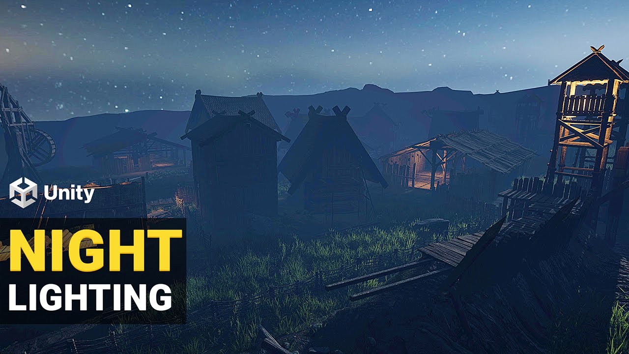
Learn how to light an exterior scene in Unity's Universal Render Pipeline (URP).
▬▬▬▬▬▬▬▬▬▬▬▬▬▬▬▬▬▬▬▬
💎 Watch advanced tutorial on Patreon 💎
http://patreon.com/uguruz/
▬▬▬▬▬▬▬▬▬▬▬▬▬▬▬▬▬▬▬▬
✅Viking Village URP
https://prf.hn/l/7aNXAQX
✅Download Free HDRI
https://polyhaven.com/
▬▬▬▬▬▬▬▬▬▬▬▬▬▬▬▬▬▬▬▬
✅PC Configuration
INTEL i9 9900K , NVIDIA...
but idk what that person is looking for, seems to be theories about distance and saturation
Does anyone know some good in-depth documentation on programming shaders in URP? I can only find simple examples and getting started guides
Hello! Looking for some insight on how one could go about using layer masks with shaders to mask out specific layers in the shader? For example, I would like to remove the pillars from the highlighted section here.

You can do lerp(sky color, background color, exp(-scatter color * depth)) where the scatter color is something like (0.1,0.2,0.4) (approximately what Rayleigh scattering is like)
The way to derive that would be to say the amount of brightness coming to you along a particular ray at a particular distance is B, and then in some distance dx moving towards you, some amount S C dx is scattered in (where S is the scattering coefficient and C is the sun color), and some amount S B dx is scattered out.
Thus we have a differential equation, dB/dx = -SB+SC. The solution is B(x) = lerp(C, B0, exp(-Sx)) where B0 is the brightness at the background object.
Here we have to assume that the amount of light reaching any point in the air is always the same, which isn't true if the sun is blocked by a mountain or something, and that the amount of scattering is not a function of position which in general it is. Either way, this is a reasonably good equation
It's the equation used to create the effect here for instance

hey folks, Im looking for answers around an intermediate / advanced question:
How can I simulate blending of normals/vertex using shader graph? I do already have a shader with the basic structure of the blend (that will be used for terrain/assets for terrain purpose) and now im stuck on this. If you have any experience on this subject please get in touch so I can share more details. Thanks in advance!!
Thinking maybe creating a texture that has the visible parts of the selected layer, then plugging that into a global variable in my shader to use as a mask.
Hey, I'm converting all my textures from tga to png rn
Is there a way to replace them in all my material at once?
How would u do it without shader
just renamed the file extension and replaced files for now lol
hey guys. I am a beginner with shaders trying to make a outline shader for educational purposes. I have a .png texture and a unlit shader replacing all transparent pixels with a green color ( if( col.w == 0) {col = fixed4(0,1,0,1); ). Except it doesn't. It looks really wierd, some pixels are replaced but some aren't. Here is a screeenshot of what I am seeing in the editor. Can someone help me ?

Check in the sprite import settings if it is imported to generate a mesh instead of a regular rectangle. The "missing pixels" might just be out of the generated mesh
yep, that was it. Thanks
sorry, i faced another issue. Whilst playing around, something happened and now the the material makes the image look like this ( see image ). I believe something was corrupted in my project, since I deleted all custom shaders in the project and added new ones, and this is how it looks without any alterations of the code of the basic unlit shader ( the one you get when you create a unlit shader from the asset menu ).

IIRC, the unlit shader is opaque by default, so what you are seeing is the RGB values of the transparent pixels I think
so i should set the Render tag to transparent ?
what should the blending be set to
I had Blend One OneMinusSrcAlpha for some reason, and it just looked like half transparent
figured it out. The Unity Manual has some examples there, and even though I don't understand them yet, I tryed all of them and Blend SrcAlpha OneMinusSrcAlpha worked
https://forum.unity.com/threads/how-to-reproject-rendertexture-from-cameraa-to-match-what-camerab-sees.1483170/
Could any one help me with this question please

Unity Forum
Let me give the detailed infomation:
I have a pair of AR glasses and am trying to align the RGBcamera image with what i really see.
First for now I...
Is modern hardware good enough for disabling/enabling shader features using branching on a uniform? I wonder if I could get rid of the thousands shader variants on projects and shave down a huge amount of build time with custom shaders.
with a little bit of the internet I created this shader, it compiles aperantly(no errors) but where are the inputs?

Hello I need help.
I am really new to shaders and all of that and i was following this tutorial on youtube: https://www.youtube.com/watch?v=jzGYXZXD7lU&list=PL0W4-LVzYmH3SWZgD1-YTd_GVlaCVaFtE&index=17
to write this shader TimerSlider.shader
but somehow this is the result i am getting

❤️ Apóyanos adquiriendo los archivos de este proyecto: -
Sigue aprendiendo shaders con el libro The Unity Shaders Bible: 🔥 https://bit.ly/ushadersbible-link
Que tal JetGuys! Somos Jettelly Team y en este capítulo crearemos una barra de energía para UI utilizando un canvas y un shader con offset en sus coordenadas UV.
DGonzales Tutoriales Espa...
Is there anything i am doing wrong?
These are my 2 assets (I did them on gimp because i dont really know what else to do and use)


any suggestions?
Is your arrow texture set to wrap in the import settings ?
Did you collapse the noise maybe ? It will hide unconnected inputs/outputs
Yes. The issue could be when different branches are called within the same thread group, but with a uniform it shouldn't happen.
Oh yeah i changed it to repeat and it works sorry its such a simple mistake but its my first time doing this
Thank you so much!!! I have been stuck for hours (it be like that sometimes)
Does anyone have any idea why this might produce some form of divide by zero at certain viewing angles?
It's all world space so I don't get it


From side
From front:

If I clamp I can confirm the whole mesh turns bright white.
This part of the graph will give a constant result, so the issue is probably from somewhere else ?
What's happening after that ?
So theoretically it would be feasible for ubershaders?
Yes
Nothing, directly into output for testing
I should note this is being rendered onto a mesh generated by vfx graph

Interesting. Is this why something like COD or Apex is seemingly compiling fewer shader variants at runtime than a simple HDRP project on build?
Compiling at runtime ?
Yeah, they force you to sit through shader compilation after each game update.
Rendering on a normal mesh looks buggy as hell, but it doesn't have the same issue.

I guess VFX graph has some limits? Are there any docs?
It's just that I work on shaders for various clients and struggle how much I should rely on uniform branching for something that'd seemingly be implemented as keywords and ifdefs in HDRP core or something. And all paid assets seem to use keywords mostly as well
HDRP/Lit shader for example already uses dynamic branching where possible, but some really "heavy" things are static branches (defines, multi compiles or shader features".
Also, HDRP & Unity beeing a "do any game type you want" engine VS custom engines from studios, it was made to give the widest range of possibilities. To reduce the number of variants you need to really inspect what features you use, disable things in the HDRP asset, and profile (the variants and keywords used)
It's a hard balance :/ Static branching will allow for simpler shaders, but breaks batches, where dynamic branching will maintain batches but may result in slower performance depending on the setup of the scene and materials :/
On modern hardware though, dynamic branching based on constant values should be almost free
Looks like it's a transparent sorting issue
Yeah I've disabled rendering both faces for now
And that fixes that issue, I'll revisit later
(Weird that the sorting issues happen on the actual mesh but not the vfx one)
The bloom problem still occurs, I've asked in vfx but I doubt anyone's going to know
It seems like a unity bug honestly which breaks my heart as it's impossible to get anything fixed in unity
Looks like you want some sort of gradient on the object. Shouldn't you use position node with object space ?
I'm looking to get the progression through the object, so I need to use the bounds
Well, need is a strong word
I could use object space and hard code the bounds and origin
But that seems unwise and unelegant
Ah yes, sorry, I've just condused my brain myself
I used a similar technique to help someone else with a shader that uses a similar technique

Which works fine, but I'm not sure why vfx fucks it up
Did you try the "absolute world" space ?
I see, so kind of a viable approach for personal projects at least.
Just did, same issue
I don't really know what absolute world is though
So I'm assuming it would break if you're on a negative axis
Setting the object to opaque also solves the issue
(But obviously, not very helpful)
It is to accommodate camera relative rendering, when all objects are virtually placed like if the camera was the world origin. iirc Only HDRP implements that.
Ah I see thanks
Using this shader on a vfx graph, I'm not 100% of what the position or the bounds would be
It matches the normal behaviour
Except at those angles
My only guess is that vfx is incorrectly providing either the world space positions of the object or the bounds at certain angles and that unity will either never fix it or fix it in about 2-3 years which isn't very useful to me
Out of curiosity, I tried quickly and it seems so that the issue is with the bounds min and max
Glad it's reproducable
I just don't know what to do as an alternative to this
I'm testing with HDRP, and it looks like the bounds are camera relative, so in HDRP at least when using the position node "world" space, it matches. Are you using URP ?
Yeah I'm using URP
Do you mean absolute world though? I'd assume world would be world relative
or is that what absolute world is for in HDRP
not experienced with it
"world" is "world space position, camera relative"
Or "world aligned position, centered on camera position"
Can you try this node setup ?

Sure, wouldn't this not work in URP thoguh as the bounds should be world space?

Yeah now it's just a constant glow
I assume that's from the camera pos addition
If for some reason VFX graph always uses camera relative bounds, adding the camera position should compensate
Given the effect works from almost every other angle, I'm inclined to think that might just be a HDRP thing
Also, the sheer amount of bloom from the error angles makes me thing it's a div by zero bounds thing
Guess I'll file a bug report, not what I wanted to waste my time doing but only chance of getting this fixed
Unity can be such a shitshow
Hey! So I'm writting a volumetric engine plumes shader, and im getting these black dots specifically when i'm looking at it from below..

Oh I will show my vfx graph as I'm unsure if I'm missing an input into my mesh draw

Well, I've just tested you original node setup on URP, and it seems to work quite fine on my side.
Using Unity 2022.3.5f1
Installing vfx graph on a test project now
And really it works fine for you with my vfx graph setup above?


Some clalculating issues with view angle ? If it only occurs when viewed from bellow, view angles or something similar might be the culptris
will look into! Thx!
I'm also trying to reproduce, I can't figure out why it's not happening
My setup is exactly the same
Except for this new project isn't VR?
But the editor isn't doing any stereo rendering obviously (I think)
You can use "mock hmd" in the editor
I've just tried, but still no issue
Yeah I'm trying in the project where the issue occurs
It doesn't seem to happen at certain positions
My best guess is it only happens in shadow? (Even though it's unlit)
Though more likely it could be a math / binary error
It appears to be tied somewhat the view position

It happens at different distances at different positions
I really have no clue here. If you submit the bug report, send the issue link here so I might be able to look at it quickly ?
I will do

My only tip off is that the depth errors happen in the vfx object too in this project
not only the static mesh
Even with the exact same setup
I'll take a break and look at it again shortly, will @ you if there's a bug report
I'm having some trouble understanding shadergraph for sprites - the tutorials and info I've found is a little dated and the output is different.
What am I doing wrong?

(ie - no effects at all, just trying to get the graph working)
(sprite unlit material)
Wrong render pipeline probably
render pipeline configured at the project level? or something in this graph
oh, yeah, that's probably it:

hm.. I added URP to this project but don't see the asset that I thought was normally created in the Assets folder somewhere..?
Pinned messages in #archived-urp for step by step instructions
k, thx
Ah, damn, that was the issue. Existing unity project that I added URP to (versus creating a new URP project which creates the asset automatically). Thx.
hey I want to create this effect, merging when the meshes collide, how can I do it without the transparency mode on shader graph? thanks in advance

i don't think you can just do that with shaders since each fragment only knows about itself and the ddx/ddy values, and same for vertices, triangles, etc. They don't know about their neighbours, let alone other meshes.
but it works on the transparency mode ):
but it looks awfull once I can see trough ):::
what does it look like with the transparency?
looks like this
Im trying to create a shader for rocks to put on terrain and "blend" both texture and normals. Im following plenty tutorials, I even bought a course. Im kinda lost :/
That's not really blending the meshes, that's the foreground mesh being transparent and letting you see some of the background. To make the meshes truly merge you would do something like raymarching (which forgoes meshes entirely) or marching cubes (which regenerates the meshes). And that's what you'd need to merge the normals.
I'm trying to make a glow outline - I'm shifting the texture to the left/right/up/down then adding them all together, but where the adds overlap it's making some funky colors.. How should I "add" textures in a purely on/off manner instead of actually adding them?

If you always know where your objects are going to be, and you know what the objects they merge with are made of, you could make some custom solution that pretends the meshes are merging without actually merging the meshes, but that only works well for simple cases
@amber saffron I managed to break it in a fresh project. It seems to be broken in a different way, but using the VR template seems to cause some kind of issue to happen atleast.
Instead of multiplying by the color first, leave the outline as white, saturate once you've added them all together, and then multiply by the outline color
i'll try that, thanks
thats the whole problem, I am in the prototype phase and Im gonna create multiple maps using the same concept, it has to give this "blend" feeling and I am looking for a shader so I dont need to adjust 3d and textures for every map Ill work on
Do the maps have to be dynamic or do you generate it once and it's done?
I've tried Interra, Microsplat and lots of tutorials. The assets are so bad in optimization it doesnt even work. 1fps
dynamic
Do you want texture blending or mesh blending
They're entirely different beasts
Hm - it looks right but I'm still getting half-multiplied green texture..?

I need both, I already found out how to do with textures.
I meant the Saturate node, not saturation. Saturate is basically Clamp(x, 0, 1)
thats how it looks so far. I still need to fix to respect the mesh its colliding with, so far it has a fixed height position

wonderful - ty 🙂

Well, as PinkPanzer said you can't blend meshes with simple shaders alone
https://assetstore.unity.com/packages/tools/particles-effects/mudbun-volumetric-vfx-modeling-177891
https://assetstore.unity.com/packages/tools/game-toolkits/clayxels-165312
If you're just prototyping I'd recommend to ignore the lack of blending for now, and when the level layouts are finished use a modeling program with a marching cubes operation to blend their geometry together
That way you'd have no trouble with runtime performance
thank you spazi, im gonn try it out]
the mesh will have to be changing while in play?
ah good then marching cubes will be good
Sebastian Lague has a good video on it if you want to implement it yourself
thank you!!!
Hm.. One problem with my glow is that the add operation at the end is adding the pink to the existing texture where they overlap. How would I combine two textures where one input would "override" the other..? (Sorry, I'm a bit new to shadergraph and thinking "in shadergraph")
the result of "add" on the pink glow and input texture

here's the relevant bit:

Do I need to do this logic-wise? Like - some sort of Any/Or/Not node magic..?
oh wait I could just subtract the original from the multiply


hi again Spazi, im trying to use clayxels but it only works with basic shapes, not with already made 3d meshes.
Can I ask what you're intended feature is?
What's the reason you're trying to blend meshes
the art direction of this project want the rocks to look like "part" of the ground, and not just placed.
You can't do that in real time
its not for real time
Then I suggest using modelling software
its for level design phase
Unity just isn't built for something like that really
You could do a ray marching thing or use that clay thing like above
I found some assets that do it, but its bad in performance
Yeah, they will be?
Microsplat, InTerra
Even in editor, these things are incredibly expensive
Yeah I think you're approaching this problem the wrong way
You could definitely write something that can do what you want
But you'd probably need a baking phase
Where you bake the blends
and even then optimising the resulting mesh will be hell
can I bake the "normals" differently? it could work
this is what I need basically

this one looks bad but, thats all
Is there a big reason you don't want to use terrain for what you're doing?
And yeah you can do whatever you want if you're making it yourself
it won't be easy, but anything's technically possible
we are going to use packages for that, so I need to blend 3d/ terrain together
at least, it must look like one thing
I made a shader that creates triplanar settings, so I can "blend" the textures, but its not enough for the art direction
Im having nightmares at this point hahahaha
Wait doesn’t real-time CSG kinda do this?
dont know, lost here
It’s mainly used as a level creator
I'm atleast 99.99999% sure that can't be used in production
nevermind mobile
shit never heard about it,
well, thats the challenge hahah
Oh nvm
Honestly, you're making a lot of problems for yourself trying to make it work like t his in unity I think
if I was you I'd look into metaspheres etc
If the world is all one big blend, how do you do LODs?
I think what you want is possible, but would require an absolute expert to get right
And a heck of a lot of time
Really simple question, I have a linear mask I'm using to provide falloff to an effect, and I want to blend it more smoothly. I'm a bit new to unity's shader graph tools, what's a good way to blend it more seamlessly then just doing a ^power?

Not sure if I understand the context correctly but smoothstep is a very common method to use for smooth interpolation in shaders. Not sure if it's exposed as a node but in any case it would be trivial to call from a custom node.
You could make a tool for generating mesh skirts in the editor. And put a terrain blending shader on them. Here's an article on mesh skirts: https://blog.gametextures.com/tutorial-enhancing-your-scenes-with-natural-looking-mesh-decals-and-skirts-bc5afe389689 Here's an article about terrain blending: https://inresin.wordpress.com/2020/04/03/terrain-and-mesh-blending-in-unity/
Medium
Building beautiful, game-ready environments is tricky. Sometimes it feels like a never ending task. There’s no shortage of little hacks…
In this tutorial I’m going to go over how to blend meshes with terrain (or even other meshes) in unity. This tutorial is fairly advanced, but I’ve tried to break it up into individual stages. I ass…
Yeah that's reasonable, I gave it a go but sadly it didn't seem to work very nicely
I'm not sure the effect is pronounced enough or something?

With smoothstep
You are bothered by the hard left edge right?
Is that where the mesh ends?
Yeah, I think my mask isn't scaled very nicely
I think it's from like 0.4-0.6, going to try fix that
Oh yeah it's because I'm doing my object space thing
Which doesn't work on a particle mesh
Which I'm forced to use as the output mesh doesn't work 😦
thank youu
Yeah this is my usual mask

Which works a lot nicer
I think the problem is I'm trying to hack this together to avoid having my effect use an actual mesh + a vfx asset
Let's start from the beginning. Why does it look like a cutoff sphere? What are you trying to achieve?
Shockwave effect thing along the ground
I'd like it to conform to geometry, and my best idea for that is using depth to fake it
As decals can't come "off" the ground at all
So this is going to be used as a decal projector?
In a sense yes, but hopefully with some more depth than that
I'd basically like the light up the mesh I have near where it meets the geometry
Which isn't a cheap thing to do
It's like water edge foam, everyone just seems to fake it using the depth texture
So like Overwatch shield then?
Been a long time since I played that, but a bit yeah
Honestly I'm going for more of a force pull effect
from like battlefront 2?
The mask goes from 1 to 0 right to left and you want it to start blending to 0 very close to the edge but still have a blend area, correct?
Hey, just out of curiosity, where do I convert the materals and textures in my game so they render properly and they aren't just a bright pink.
Yeah it works fine outside of vfx graph
Top menu, Assets-Render Pipeline-Convert Materials I think.
I know sort of what I'm after I'm just uncertain of how to make it work using unity's framework
Especially since I discovered a bug in the engine doing it my first way
Well, if my description is correct, you didn't just pass 0 and 1 to as min and max to smoothstep right?
Honestly I have that issue solved, I know what was causing it and smoothstep works fine with the masks setup properly
I'm just sort of re-conceptualising how I'm going to have the effect work
I might need to just have the mesh as a static mesh
Min will define where your blending will start and the distance between min and max how fast the blend will be so playing with those values usually helps tighten the blending up. Okay, just making sure. Solving shader issues out of context is so troublesome ngl.
I can't find it
I'm probably just going to throw out this shader and work out another effect haha
Not sure if I was even helping, still not sure why a shockwave isn't a full half sphere 
I was trying to sort of make it look like dust being disturbed along the ground or something
I don't know really, it was an early concept
Just didn't want to block view of the actual interaction with the world too much
To upgrade built-in Shaders:
Open your Project in Unity, and go to Edit > Render Pipeline > Universal Render Pipeline.
According to your needs, select either Upgrade Project Materials to URP Materials or Upgrade Selected Materials to URP Materials.
Sorry, here's the correct instructions.
Ohh, so the shockwave would start from the left and go right. I was thinking it's weird that the expanding side is a straight line.
Oh yeah exactly haha
Incindentally, is there a way to spawn particles along the ground in a relatively inexpensive way?
In VFX graph?
Well, you'd kinda need to raycast from your own script to sample the ground and pass the data to your graph through a binder I think.
Yeah that's what I was afraid of, seems like that's going to be too expensive for standalone vr
Especially if I want to conform to non-flat ground
Ah, we're not talking about one and done particles hovering close to the ground?
Yeah sadly not, the reason I wanted to use the depth is it would follow the ground / nearby geometry very well
And be very inexpensive
You can optimize with the jobified RaycastBatch API or whatever, I spammed a crapton of raycasts every fixed update in my parkour project.
Like 800 I think?
That's pretty cool, I might do that, sort of do a row of raining raycasts along the ground
Even just 10 a frame would probably looks pretty cool
Doesn't vfx graph have something for floor colliding particles?
Or is that just within volumes?
It has depth buffer sampling but that's limited to objects that are visible to the camera, yeah.
Very new to vfx graph, trying to get my head around what exactly it can and can't do
I've also done rain drops collisions supporting off screen occluders by spawning an orthographic camera looking straight down, sampling its depth buffer, converting the depth value to world space using the rain camera parameters and then calculating whether a particle hit the ground by comparing its world position.
That's a pretty neat idea
What's your parkour game?
It was a prototype that I dropped after burning out. Made the character, animations, basic gameplay mechanics and climbing but trying to design open world parkour locations with no game design experience was too much
Ah that's a shame to hear. I'm sort of the opposite, I've been mostly a modder for quite a long time, so my experience with animations and modelling is a little limited, but modding allows you to focus on game design a lot easier
Got any clips from your work on it?
Yeah, I really wish I had that experience but don't think there are even non puzzle games with a level editor these days.
you'd be surprised, depends what communities exist, the collective efforts for some games is very impressive
Sure, scroll down to LIMINAL;WASTE https://beatrate.github.io/
very cool, mirrors edgey
always loved that game, shame the new one was a bit lukewarm
Ah, I also remember that my hook was grinding on rails in first person but that turned out to feel like crap. Turns out a big part of why it was fun in Sunset Overdrive is that your camera wasn't attached to your body.
Yeah, Mirrors Edge was amazing, I had it open constantly for referencing while working on this.
Sadly I couldn't accept making a game where there is no hook except "look it's linear Mirrors Edge again" and so I canned my game 😄
Yeah very true, still I think the mark people miss on single player experiences like that is that a narrative can really tie it together
Poor story really hindered mirrors edge cat
Yeah, I don't even remember the story of the sequel, all I can remember is constant backtracking and wishing for unique levels that stand out between each other like in the first game.
Yeah it's the soul a lot of games are lacking these days
Even indie games don't seem to get you can't make a game out of a few mechanics
Except like... BeatSaber
How do you guys tile your tiles without making it repetitive when zooming out? I think it is called Stochastic tiling or something? I can't find any tutorials that are under 4 hours for what should be a simple thing?
Looking for insight on how one could apply a screen space shader only onto specific layers (like player and enemies). Been kinda stumped on this for the past few days.
What render pipeline?
Also what screen space effect
I meant full screen shader. Using URP. I'm basically trying to mask out specific layers.
It's definitely possible using a custom render feature, I've not done it in URP though. You'll probably need another camera or something. There should be some tutorials for this out there, it's a common thing to want a "senses" like view of the scene
And xray through walls etc
This is what I've been doing so far, through a custom render feature. Following this thread:
https://forum.unity.com/threads/filter-on-layermask-renderpass-scriptable-render-pass-render-feature.1338947/
Unity Forum
Hi Guys
Looking at this video . I want to leave my game in Full res but only pixelate one layer.
[MEDIA]
Cause of all the jitter in Pixel perfect cam...
I am newer to render features so that may be it lol I just might need to get good.
But at the same time, still feel lost on this one.
Simple question, any way to bend node links like in other programs? Just to tidy up the node connections?
What's the best way to learn shaders with HLSL and not CG?
there are these little nodes you can add, i think they're called redirect nodes?

like node cable ties
Yeah exactly that
I just don't know how to add them in unity
How do you do it?
i believe you can right click on the connection and there's an option for it
Cry, repeatedly for several weeks
Jokes aside, a bit of GPT, a bit of decompiling shader graph nodes, and a whole lot of googling
Not for me, in vfx graph atleast
oh idk if they exist in vfx graph
Yeah I don't think they do, right clicking does work in shader graph
sad
wtf is unity doing behind the scenes that these systems aren't using the same code
I made a shader with the graph before realizing that you cannot modify the zbuffer so it was essentially useless
Then I just converted it into an actual shader only to suffer for a couple of hours and still haven't figured out texture scaling/offsets
I have no idea how custom functions really work, but you have access to some variables
It's a miracle I even figured out how to sample a texture
did you try editing it through there?
I think all my future shaders will be shader graph with hlsl custom functions because honestly the hlsl documentation is complete shit.
Unity says don't use CGPROGRAM anymore but there's little to no documentation for HLSL
I need to learn shaders anyway
Like HLSL
Shader graph is cool and all but nothing beats real programming
Unity has really got to stop supporting this stuff
Shader graph has it's boons
It's very hard to make syntax type errors
But yeah I agree the HLSL docs are piss poor
CG is a subset of HLSL.
Sure but they do things in a much different way.
Basically all core functions have a different name in pure HLSL
The advice I got was this:
"For URP/HDRP, you should be using HLSLPROGRAM. Either way, it's all HLSL, but if you use CGPROGRAM, Unity will automatically include some functions and types that are found in CG, which you don't need for URP/HDRP."
From you
So I'm trying to create a shader that receives shadows casted by other objects, but for some reason the shadow dissappears at certain camera angles

Pastebin
Pastebin.com is the number one paste tool since 2002. Pastebin is a website where you can store text online for a set period of time.
I have no idea whats causing the issue
What have you tried?
Do you have a video?
Is that purple ball the "wrong" result?
What core functions have different names?
Off the top of my head things like sampling depth, all the samplers and vertex inouts seem different, even the naming style seems different?
Those are not part of HLSL or CG. Those are Unity functions, which are different between render pipelines.
this here is the code
you're doing a whole lot of stuff there
Try break it down to just the shadow attentuation stuff
and draw 0/1 based on in shadow or out of shadow
See if that's still broken
how do you do that?
Basic debugging, what's the minimum broken example
is this your code?
yes
Ok so im trying to create a cel shader, originally it was a surface shader
but it had issues with receiving shadows
Where the shadow being casted didnt match the cel shading

weird when i do that it still has the shadow ontop of it
let's see
it's hard to debug without seeing
shader debugging is a whole lot of just outputting different things to see if you're getting what you expect

okay so it's a shadow attentuation thing, which means either your usage of it is wrong, your v2f i is setup incorrectly, or it's a unity bug
is this URP?
yeah that's about as far as my knowledge goes, I'd read up on SHADOW_ATTENUATION
see if you're doing anything wrong
Cant find much about it
everyone is so damn vague about shaders and receiving shadows in general
its frustrating
It's not a simple subject really
My recommendation would probably be to find a toon shader you like and work backwards
There's an old unity one for BIRP I think
The problem is most of those dont receive shadows at all
or have some other issue (IE: only get one light, don't use colored lights)\
Learn to write a toon shader for Unity engine with specular reflections, rim lighting and shadow casting.
Have you seen this?
He provides source
I'd try get his to work if it doesn't seem different to your own
I tried that one while it receives shadows, it doesnt get colored lights
I don't see why you couldn't extend it to that yourself
good point
How could i know how many instances of materials are in the scene?
Does anyone have experience with rendermeshindirect?
I think it allows you to add a drawing command that will be executed whenever unity starts to render
I have an experience with Graphics.DrawMeshInstancedIndirect which is the same thing.
does anyone know how to orient textures to wrap facing world up? I describe what Im trying to do more here: https://forum.unity.com/threads/make-texture-always-face-direction-ie-aim-arrow-at-world-up.1484076/
basically I need to orient a texture so the textures up is always world up, one example of this being useful would be for getting a rain streaks texture to orient correctly on an object that can rotate around. surely plenty of people have done this before, Im surprised I cant find anything on it, maybe Im just not searching it right
Unity Forum
hey guys, having trouble doing the title or finding resources on it even though I imagine plenty have done it before.
I would like to do some shader...
for the most part you just ignore the UV's and use world coords instead and divide them to get them into a resonable range to sample your texture
would look up Triplanar Mapping as a example
though you do not need to use all 3 dimesions depending on your purpose
oh triplanar makes sense let me look into that, thanks!
more or less can use world coords brought back down to a resonable scale to sample your texture, from the XY plane, YZ and XZ planes
then you can use dot products of your normal with, forward, side and up directions to create masks for lerping between those projections
can get the abs of each dot product so i can mask in both directions along that vector
thanks for the help again this is exactly what I was trying to do. I should have thought of triplanar since I was just using it in substance painter, seems obvious in retrospect :p

I know I already made a similar thing in another channel, but I'm trying to make a sprite have the same color (or costume) as another.
How do I make the light beam for a flashlight to add with the spotlight?
does someone understand hwo paralax displacement works, because I feel like I kinda fucked up mine
that s my implementation

void calculateUvOffset_float(float displacement, float amplitude, float3 viewDirTS, out float2 offset)
{
    displacement = displacement * amplitude - amplitude / 2.0;
    half3 v = normalize(viewDirTS);
    v.z += 0.42;
    offset = displacement * (v.xy / v.z);
}
It looks kind of correct, even if I don't really get what is the point of the z axis of the view direction here 🤔
it s an offset, kinda some fine tuning everything else looks even worse
Well, you have the exact same code as the shadergraph parallax mapping node, so I'd expect it to work 🤔
https://github.com/Unity-Technologies/Graphics/blob/master/Packages/com.unity.render-pipelines.core/ShaderLibrary/ParallaxMapping.hlsl#L30
yes it kinda works, I will compare it to the parallax node before I keep asking questions
yeah turns out you need occlusion parralax mapping which is like a recrusive algorithm
It looks better indeed but is more costly.
The POM method is here : https://github.com/Unity-Technologies/Graphics/blob/master/Packages/com.unity.render-pipelines.core/ShaderLibrary/PerPixelDisplacement.hlsl
But you need to setup the params struct for it to work : https://github.com/Unity-Technologies/Graphics/blob/master/Packages/com.unity.shadergraph/Editor/Data/Nodes/UV/ParallaxOcclusionMappingNode.cs
Might be simpler to just look at the shader generated code.

GitHub
Unity Graphics - Including Scriptable Render Pipeline - Unity-Technologies/Graphics
GitHub
Unity Graphics - Including Scriptable Render Pipeline - Unity-Technologies/Graphics
Hi everybody,
I just created my first shader with the help of this https://www.youtube.com/watch?v=cUTgucRsOPY&ab_channel=Licke tutorial.
I am trying to create 3d clouds (just a few big fluffy ones not the whole sky).
It almost looks like I would want except that if I place 2 spheres next to each other and they intersect it's very visible any tips to eliminate this?
And make it more uniform?

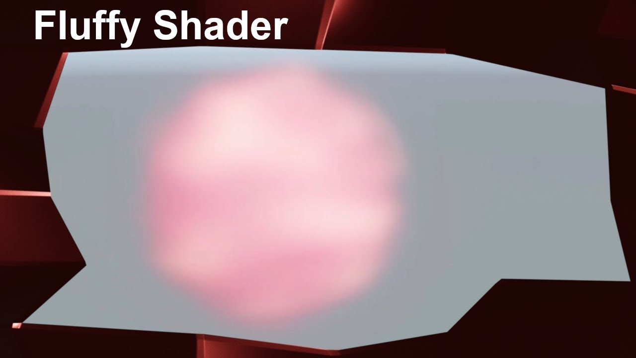
Unity Shader Tutorial: Fluffy Ball Shader [Clouds/ Cotton Candy/..] #MadeWithUnity
In this Unity Shader Graph Tutorial I show you how you can create a fluffy ball shader. This shader could be used for things like cotton candy or clouds.
Unity Version: 2019.2.13f1 (using the LWRP/URP)
Music used:
Nathan Moore - Checkmate
Chris Haugen - Mind S...
thank you
well one way to make it would be to combine the meshes
Ah yeah that is a good idea actually 🙂 working on it
Got a question! Currently masking out layers with FilterSettings in render features but I was wondering if there was a way I could mask out the pixels that are blocked by other geometry on screen?


Hello, I'm new to shaders completely and kind of want to start practicing. I've looked into the documentation and just want to know whether there are any other resources you guys recommended - thank you
Interested mostly in lighting shaders like rim lighting and such
FIGURED IT OUT I JUST RENDERED IT AFTER RENDERING OPAQUES
Okay maybe I didn't. Is it possible to use rendering layers with shaders as of now? Like a full screen shader?
You could change the blend mode to additive
That would create a different effect though, maybe combining meshes is best for you
how exactly would one grab uv data from another shader (urp render features)?
e.g. lets say I have one shader that manipulates screen color UV, and i have a second shader I want to apply that needs that UV or it winds up overwriting the previous shader
Guys I'm making a hlsl file for toon shading. I tried to call 'GetAdditionalLightsCount' function to make the material work for multiple lights. However If i put the code into urp unlit shader and apply it to custom function node, it shows the error 'Undeclared identifier'. I thought GetAdditionalLightsCount function would be built-in function that can be used without any specific custom definition. My unity uses 2022.3.5 version. Should I include some files or?

Plus, also my shader grpah doesn't recognize 'Light' type in hlsl. I'm just trying to do the same code at 17:10 on this video in the link. Is this related with version problem? I'm not sure about whether 'Light' type and 'GetAdditionalLightscount' function got deleted on the higher versions of unity.
https://www.youtube.com/watch?v=RC91uxRTId8&list=PLAUha41PUKAasDP7TOMBRramS5mkQ0hIG
✔️ Works in 2020.1 ➕ 2020.2 ➕ 2020.3 🩹 For 2020.2 and .3:
► When you create a shader graph, set the material setting to "Unlit"
► The gear menu on Custom Function nodes is now in the graph inspector
► Editing properties must be done in the graph inspector instead of the blackboard
► In Lighting.hlsl, change the line "if SHADERGRAPH_PREVIEW" to "...
How can I write a vertex fragment shader to work with full screen effect in URP?
You should be surrounding the body of your function with #ifdef SHADERGRAPH_PREVIEW as these Light/GetAdditionalLight/etc only exist within the URP Shader Library which isn't used within shader graph for previews.
Also make sure GetAdditionalLight call contains the correct number of params, it does keep changing so tutorials can get outdated. You can check the definition under the URP package, ShaderLibrary/RealtimeLights.hlsl iirc. I tend to use GetAdditionalLight(lightIndex, WorldPosition, Shadowmask) but if you don't need to support the baked shadowmasks (SAMPLE_SHADOWMASK(lightmapUV)), can use half4(1,1,1,1) instead. The param is still needed for it to calculate shadows for some reason.
(Might also help -
https://github.com/Cyanilux/URP_ShaderGraphCustomLighting/)
Should be able to include & use Blit.hlsl (it contains a bunch of vertex and fragment shaders for you, could copy and edit them if needed). Apply the shader/material with the Fullscreen Pass Renderer Feature (provided in 2022.2+) or another feature using the Blitter API.
https://github.com/Unity-Technologies/Graphics/blob/master/Packages/com.unity.render-pipelines.core/Runtime/Utilities/Blit.hlsl
You could separate the UV manipulation into a separate pass. e.g. Have all the UV offsets calculated and output to a different RenderTexture target (likely additively using an RG format). Then pass that texture into a fullscreen pass that applies the distortions using it.
If the feature uses ConfigureTarget, make sure you use the camera depth target as the second param. Also set the feature to render after other objects, AfterRenderingOpaques as you mention should work.
It'll depend which render pipeline you intend to write shaders for (and what tools you use, i.e. Shader Graph or writing code)
I've got a list of tutorial sites & resources I've found useful here - https://www.cyanilux.com/resources/
I ended up writing the fragment function into an hlsl and sticking with the URP default full screen shadergraph.
Can I ask if there is an easy way to enable/disable this effect?
I'd serialise a FullscreenPassRenderFeature (or ScriptableRendererFeature) field on the component where you want to toggle it. Will need using UnityEngine.Rendering.Universal;
Should then be able to use .isActive = bool or SetActive(bool)
So I have this issue where if received shadows is on, an extra shadow is added on top of the shaded area, I want the two to be the same color. Anyone know how to do that?

Pastebin
Pastebin.com is the number one paste tool since 2002. Pastebin is a website where you can store text online for a set period of time.
here is the shaderlab code
I'd probably remove * light on line 79 and do lightAmt *= shadow; instead before the ramp sample
Thank you
Hello, beginner question regarding texture atlases. Is it better to have 4 1K textures or 1 2K texture which is an atlas of the 4 1K?
When I check resource cost, 1k textures weights ~1.33Mo in GPU and the 2K texture weights ~5.33Mo. So is there any point to create an atlas like this?
The only difference I see like this would be the number of texture would be reduce, but the weight stays the same. Does the number of textures in GPU impact performance that much? Or is it only weight>
I'm thinking of using shader graph with the flipbook node to use atlases but not sure it's worth the effort in the end.
Any insight on this topic is more than welcomed 😄
Aha found some of you knew it 😂
IDK for sure but if there's still the same amount of samples I'd expect both to perform similarly.
I think atlases come in useful when you have various meshes which share the same shader (& property values) but use textures. By combining the textures into one, those objects can share a single Material asset, and so batch together.
Though now in URP/HDRP the SRP batcher can batch different materials provided they share the same shader, so I don't know if atlases are still as useful. Perhaps others will know more
Got it, I was reading about this material sharing advantage, but since for my project, the same material could be colored differently by the player (like hair color), it means it's not really useful, plus I do use HDRP and like you said, I did read somewhere it should batch more efficiently.
Thanks for the confirmation!
Hi, I have an hlsl script that sets mesh instances transform using DrawMeshInstancedProcedural() (in URP), how can I set a different color for each instance too?
 #if defined(UNITY_PROCEDURAL_INSTANCING_ENABLED)
    StructuredBuffer<float3> _Positions;
#endif

float _Step;

void ConfigureProcedural () {
    #if defined(UNITY_PROCEDURAL_INSTANCING_ENABLED)
        float3 position = _Positions[unity_InstanceID];

        unity_ObjectToWorld = 0.0;
        unity_ObjectToWorld._m03_m13_m23_m33 = float4(position, 1.0);
        unity_ObjectToWorld._m00_m11_m22 = _Step;
    #endif
}
Add another StructuredBuffer for colours, or convert the existing one to a struct type containing both
Yeah, but what's the buffer for that if you know it? I've searched in the unity documentation but I haven't found it
Would likely be float4. Though if you don't need an alpha channel you could use float3 (but you'd probably need to format the data in a Vector3[] on the c# side when setting the buffer then)
I'm using compute shaders so I'm fine with float4. So is the color information stored in the unity_ObjectToWorld matrix or it's elsewhere? That's the part that I'm missing 😅
No, you'd pass the colour from the vertex to fragment shader via your own interpolator (the vertex shader output, usually Varyings/v2f)
Or just read the buffer in the fragment shader I guess
Thank you very much 🙂
One of the things to consider is memory/cache coherence. So it may be that accessing a single 5.x K texture is more coherent and thus faster than 4 separate textures separated in memory. The only real way to tell, though, is to benchmark the results. The thing is that GPUs are built to access multiple textures in a shader, so they have "tricks" to level off the time by suspending the running instance and starting up a new one and working on that until the result comes back from the sampling unit. But still, you may find that having one texture if it has enough resolution is going to be closer in memory and thus more cache-hits.
is there a way to have more than 8 uv channels in a mesh and access them in shader
how many do you need?
Well, you don't HAVE to store it on/in the mesh data.
structuredbuffer is not ideal because of random access lookups if thats what ur getting at
this is on mobile hardware so there's going to be a hit there
You only get 8 UVs with unity's mesh API.
Since you're talking about a UV you might be able to pack more data into them though. For example using a float4 you can pack 2 uvs per vert per channel. I think.
The https://docs.unity3d.com/ScriptReference/Mesh.SetUVs.html API supports a Vector4 from C#.

I suppose there's also packing more data by sacrificing precision in the float, but that can leave artifacts. For example the int portion and the fract portion of one float holding 2 values.
I'd need at least half3 per channel so not much gain there. Hmm.
Well, if float4 works you have 16 float2's. That could map higher if you're using halfs
So test it. Across APIs
true, aight bet. Thanks @meager pelican
If anyone is interested I've solved my problem with a custom function in the shader graph and the .hlsl script below. Thank you @regal stag
#if defined(UNITY_PROCEDURAL_INSTANCING_ENABLED)
    StructuredBuffer<float3> _Colors;
#endif

float3 GetColor()
{
    #if defined(UNITY_PROCEDURAL_INSTANCING_ENABLED)
        float3 color = _Colors[unity_InstanceID];

        return float3(color.x, color.y, color.z);

    #elif !defined(UNITY_PROCEDURAL_INSTANCING_ENABLED)
        return float3(0.f, 0.f, 0.f);
    #endif
}

void ColorFunction_float (out float3 Out)
{
    Out = GetColor();
}

void ColorFunctio_half (out half3 Out)
{
    Out = GetColor();
}
There is no node for matrix inversion in Shader Graph?
AFAIK transpose is only part of matrix inversion operation so not really
I read about using C# scripts to pass data to a material which I can then use in vertex/fragment shader functions. Any info about how much that might affect the performance on the shading? I am experimenting with manipulating the vertices by using the vertex color (as weight) and a passed in velocity vector from a C# script to deform a mesh. Just an experiment but I wonder if cloth simulation is utilizing something similar?
Hey! Would anyone know how to get "moving noise" similar to this using shaderlab? Would it be the matter of changing variables in an attached c# or is there a function already in shaderlab?
https://fxtwitter.com/ItsRyanAnderson/status/1695438447287451676?t=6cwhNMoJ5grii86WWSvC6Q&s=19
Weekends are for getting in touch with nature👑
my guess is have something for a noise texture, then make the position randomized, IDK I havent done this
how would one go about creating a distance based fog shader? I know i need to do something with scene depth and lerp but im not sure how exactly im supposed to put everything together
lerp between the scene color node, and some color, using lineardepth as a t value
okay so i have this right now, though it only works if the end distance is stupidly small, and it has the same problem that the built-in fog has, where it moves with the camera making it look ugly against a wall

(actually it requires a less stupidly small distance in game view, but still a stupidly small distance regardless)
You probably want a distance based fog instead of depth based.

Some information about that can be found here:
https://forum.unity.com/threads/computing-world-position-from-depth.760421/#post-8623839
okay well now i have this set up but im not sure where to plug it into since just using the output from the last add node does this (and also does it specifically from 0,0 rather than the game cam)


Does anyone know how to recreate a texture or wall like this in unity? The photo shows a wall in bonelab the video shows 2 other games. If anyone can tell me please DM me or reply to this message.

I am quite new to unity so this might be a pretty dumb question.
It's not dumb, there are many ways to do it. I imagine the way they've done it makes it so you can have a panel anywhere and it'd render sky?
If so, then it's probably some sort of cube-map like rendering for the sky, and then the panel has some normal UV'd lines on it.
There may also be some offset to those UVs that they use when sampling the sky, a tight grid to give the look of refraction through their faux pixel grid
How do I do that?
I am new to compute shaders but had a play around with indirect instances. I build an array in the editor and hand that off to a computebuffer along with an arguement buffer, calling DrawMeshInstancedIndirect with these buffers. It works great! I would still like to improve this with frustum culling and LOD if I can figure it out. I'm stuck on how I can change the number of instances without moving back and forth between the cpu and gpu. I know you can solve this on the GPU and keep everything on that side. How should I be solving this? How can I change my arguement buffer on the fly?
You might not have to. So let's say you have a structured buffer with 1000 instances of arguments. But you want to frustum cull, on the CPU side, the object array that you pass to the GPU.
The problem this creates is that once you do the frustum culling, the index #'s don't match between the CPU generated list of the, say, 500 that passed culling and the total list of 1000. Right?
Here is an example of where I am at without LOD or culling
So what you do is make another list! It sucks, but rather than having to remake the argument buffer every time, you make a frame-to-argument buffer map of ints, that just has the index numbers of the passed 500 items that directs them to the index of the main argument buffer.
sec
OK, I get it. You're keeping a large list of objects, and want to cull them. You can do a test on the GPU too, but that seems a bit much since you'd have to pass the data to cull it later on the GPU.
And you're pointing at different meshes with different verts...not sure how you're doing that...maybe passing multiple lists?
Like you're showing 3 in the vid, cube, sphere and torus

Yes, I have it iterating a few times for unique meshes, but if I cen get it working (culling) on one mesh then I will do it to all.
Did the mapping list make sense?
So if you have a list of, say, 1000 cubes. And all their individual unique values....
and let's say only 50 of them are visible on the screen, the others are culled on the CPU side when you build your list for the procedural draw call....
you pass an array of "visible cubes" and that array is 50 long, and it contains the index values that will point back to the argument buffer. So instances 1,2,3,28, 93, and 599...are visible.
That way you don't have to resent the argument buffer every time.
and the mapping list is small, just containing ints.
That makes some sense. So the arguement buffer will always remain larger than the list of items being drawn.
Exactly, unless they're all visible. Then it's 1:1
I'd really like to work out how to do this entirely on the GPU.
There is an example on Github here: https://github.com/ellioman/Indirect-Rendering-With-Compute-Shaders , but I can't work out how it is being done - even with the code right in front of me... Maybe need to stare at it a bit more.

GitHub
An example of drawing numerous instances using Unity3D, compute shaders and Graphics.DrawMeshInstancedIndirect with Frustum & Occlusion culling and LOD'ing. - GitHub - ellioman/Indi...
This even has occlusion culling which is even beyond my dreams.
My code is happening at a much lower level.
I mean simpler, smooth brained level.
There are many techniques used in ray-tracing that use intersection tests. Those are often done "in reverse" of what you're doing, having a ray and trying to find all the objects that it intersects. But these methods have intersection tests...you want the one that intersects an AABB (axis aligned bounding box) with the current frame's view frustum. That will give you some google terms.
For example, just googling this brings up things like https://my.eng.utah.edu/~cs6965/papers/p1176-reshetov.pdf
https://bruop.github.io/frustum_culling/
SIMD Frustum Culling
Your argument buffer could contain the bounding box info.
I am not at the point of solving the culling algorithm yet, more just trying to work out how to change the list of drawn objects on the gpu. I'm travelling slowly.
But be warned, you're still doing potentially many many more draw calls than you need to, unless you come up with a multi level approach and use an append buffer and build in intermediate list of "visible things" via the GPU rather than the CPU.
I don't understand this post.
A victory for me would be doing a simple distance test and culling from that - that would be useful for the LODs as well.
Sure, you could do a sphere test for example. The object's center and a radius. If any of that sphere is inside the frustum, proceed. But there's issues....
When you do procedural calls, you do them either directly or indirectly.
Directly you pass the # of instance you wan to draw (maybe it's verts...so #instances x #verts-per-instance).
Indirectly, you have a list on the GPU, and that sets it all up.
What type of draw call are you doing?
AFK for 10 minutes.
See https://docs.unity3d.com/ScriptReference/Graphics.RenderPrimitivesIndexedIndirect.html also.
OK, so you already have a buffer that holds the information for the indirect call.
I think I will need 4 buffers for the culling to take place. Like you mentioned 2 buffers will hold the total data, and the other 2 will hold the culled data. DrawMeshInstancedIndirect will then be called using the second set.
So both the list and argument will be created on the GPU
THanks for adding your brain power.
Compute shaders are good for making that list of visible objects. If all your target platforms will support them.
And you could use an appendStructuredBuffer for that, and then consume it in the mesh draw calls.
IDK if you want to also investigate procedural calls, but they're there.
There's API calls to get the size (result) of the append buffer on the CPU side so you know how to invoke the next step.
But you might only need ONE rebuilt every frame. Indexing into the "total data" buffer.
Thats what I am going to try. It will take me a while to set up the test, but at least I have an experiment to try now - thats what I was looking for. The next step, so I appreciate it. I'll post back if I have any success.
Dont want any trouble with the mods.
How do I get to this screen? Is it a shader? As I said I am quite new to unity

It's Shader Graph
(see pinned messages)
Alr thank you.
I am very sorry for all the questions but how do I get this?

Is there a way to port this kind of pattern from blender to unity shader graph, I am using this addon https://forum.unity.com/threads/beta-blender-nodes-in-unity.1249171/


Unity Forum
Hello, I'm Warwlock. I've been developing games over 8 years. In the last years, I got interested in shaders and node graphs. But like most of you, I...
That is irrelevant. Just connect the sample texture node to the multiply
it also shows this here.

for every single one
I imagine you haven't added any active targets or something. Look in the graph inspector and make sure something is listed


oh
There is a material under the graph asset, use that if it has all the settings in it, or make a material that is set to use your shader
That's a redirect node, i believe you can click on the connection and there's an option to add one. They don't do anything at all, they just let you move the lines around to make things neater. Basically a little cable tie.
They have no effect on the compiled code or performance or results
Shader graph noob here. I have a scrolling texture shader with a pixel art texture. I want it to tile in the y-axis but stretch in the x-axis. Currently, when I apply it to a larger face, it stretches it all out and makes the pixels bigger (urp)


I think the easiest way is to stretch the incoming uvs?
Can you give an overview on how I would do that?
See the UV component in the tiling and offset node?
You want to stretch the UV going into that (or out of that, it's all the same)
There may be a way to make it auto-fit, I don't do much 2D though, you can probably find on google if y ou can
.
Is there any way to sample the scene colour for meshes that distort their background after transparent objects have been drawn?
I know this is a pretty difficult thing to do, I'd like to distort the view through meshes without having my entire ocean disappear behind it
Is Tiling set by a script or something?
How do I correctly interpolate camera direction vectors from vertex shader to fragment shader?
Assuming I know the camera direction of a vertex in the vertex shader
it should do it for you
there are different interpolation types also
yeah, and I can't wrap my head around them, I mostly need a "camera direction" vector working for both perspective and ortho
and right now I do it in a veeeery suboptimal way
shader graph? or hlsl?
HLSL
Is that not just the view direction/camera orientation? (I think both of those can be accessed without needing anything custom)
because in the fragment shader I use inverse perspective projection of fragment to NDC, calculate direction from this by setting Z=0 and Z=1 (projected onto near and far planes) and then back to world space
so wait you want the world space position of a pixel?
otherwise, you can get view dir in the vertex shader
and that works pretty fine
That as well, but that I do with depth buffer -> world space
for context I do raymarching
not sure about which one you talk about
but even if it's the shadergraph one, it defines camera forward direction, iirc
no it's the view direction
for my raymarch shader that works fine, other than it's not got a meaningful magnitude
so i use a different hacky way which I can use to measure the distance of a pixel from the camera
does it work for you in orthographic projection?
what I ideally would like is this

I honestly haven't tested with orthographic
I'd assume it's an easy fix, after all the ortho calculation is very simple
I already have to do some extra changes if stereo rendering is enabled
hmm, maybe I have been doing something incorrectly before and didn't notice? Simple lerp between unnormalized directions should work. And direction should be easy to get from vertex-camera in perspective and camera forward in ortho, which is then picked based on isOrtho variable

red is incorrent direction calculated from lerping normalized ray direction vectors for vertices, green is just lerping between vectors from camera straight to points without any normalization
I exported an object from Substance Painter with Opacity , and It didn't appear as I wanted, the grip is not supposed to be transparent


Can you see objects behind it? It looks to me like the main issue is that the back faces are sometimes being rendered in front of the near ones, which is something that happens with transparent objects and can be avoided by making them convex and culling the interior. Just looking at the right image, this seems like a good use case for alpha clipping; that would allow you to make the object opaque (thereby avoiding issues with transparent objects) while still having areas of the mesh be invisible. (Transparent shaders are needed when you want something to blend with the background, so alphas between 0 and 1 or additive/multiplicative blending)
Yes I can see objects through it , and here a picture to the object with Opaque and with Transparency

I meant through the handle rather than the mesh, sry. It seems like it is blocking the background as it's supposed to, just the faces aren't ordering properly. Try using alpha clipping instead, since the faces will be correctly ordered then

You mean #ifndef, not #ifdef? and is this becuase URP shader library, which includes Light/GetAdditionalLightsCount/etc, is not included in shader graph when previewing? The error fixed when I added #ifndef SHADERGRAPH_PREVIEW but not tested about whether the function works well yet.
Yeah, though either works if you use an #else block. May need one anyway as the out params need to be defined in both code paths
Thank you very much, it works

For some reason I have this issue where certain parts aren't lit by light even though they should be (such as how the front legs arent lit like they should be)

Pastebin
Pastebin.com is the number one paste tool since 2002. Pastebin is a website where you can store text online for a set period of time.
heres the code
its not because of the model, because with other shaders it works fine
Im not sure what's causing this
You so genius bro thx!
Hey, I'm working on stylized shader that requires me to somehow pass 3 different colors to deferred shader, I was thinking that since I'm not using specular part of gbuffer I could use it for one, and shadowmap one for the other, but it seems like urp won't pass the shadowmap one just because I output something there and I can only use it for the shadowmap. Any way to get that extra gbuffer space? Or maybe there's a different way to share those colors between passes?
Hello I am trying to mix three textures based on noise (where all of three textures should be like 33% of the final result) - but unfortunately it is not working.... any tips how to do that?

How do I make Unity not compile a ridiculous number of variants for litereally the simplest URP Lit SG in my project? 😮
I was able to reduce it a bit by removing DX11 and DX12, but... there has got to be a way to tell it that 99.99% of the keyword combos are completely bogus shit that nobody ever needs?

No asset in my project does anything fancy. Always the same scene. Always the same fog. Always the same. Same, same.
I think this could boil down to < 100 variants, possibly < 10.
I know about Shader Variant Collections, I hate their editor almost as much as the Assembly Definition Editor. 😉 But I have a pretty stringent one set up. Still 6144 vp just on that one shader alone.
You will probably want to use blend nodes, also Clamp your Noise as it can generate negative values You'll have to experiment with ratios to fit your needs

ah, the URP experience
What version of Unity are you using?
float3 lightDir = normalize(_WorldSpaceLightPos0.xyz); //light direction
I think this is not light direction, it's light position.
You might need to substract _WorldSpaceLightPos0 with WorldPosition to have light direction
[Edit]
Or maybe it should be worldposition substracted by _WorldSpaceLightPos0 🤔
How can I write a shader that raymarches from one triangle (the first along the ray) then stops once it hits the next triangle along the ray
like this

doesnt work, also it worked fine in the first pass
I want to make custom fog shader and I already did (using shader graph*). However I would like to apply this custom fog shader to all scene objects instead of having to drag the material to all scene objects.
Would this be possible with custom passes or post processing etc
quick question, why can i not edit the values of the material i made with shadergraph, in the inspector?its all greyed out

ohh i needed to click "create variant for renderer"
If you want to do it on a per-triangle basis, knowing the attributes of the triangle's material, you'd have to upload ALL triangle data to a big-ass buffer on the GPU. You'd have a triangles buffer, and they'd have an attribute that indexes to a material's buffer. There's usually a "mesh buffer" too, so you can cull whole objects from your search.
You'd probably use an acceleration structure such as AABB's space-partitioned into a BVH tree. You'd search the tree for the nearest triangle, perhaps in your case the one past the first one...but to do that you'd have to know what triangle is closest, and then figure out what one is 2nd closest. That could all be done in one search though. You "just" want the 2 nearest ones.
The GPU doesn't retain any polygon data past the current mesh it is drawing...you have to do it all manually in code.
Shader "Unlit/ShaderUnlit1"
{
    Properties {}
    SubShader
    {
        Tags
        {
            "Queue" = "Transparent"
        }

        Pass
        {
            CGPROGRAM
            #pragma vertex vertexShader
            #pragma fragment fragmentShader
            #pragma alpha:fade

            #include "UnityCG.cginc"

            struct MeshData
            {
                float4 vertex : POSITION;
                float3 normal : NORMAL;
                float4 texcoord : TEXCOORD0;
            };

            struct InterpolatedData
            {
                float4 vertex : SV_POSITION;
                float3 normal: NORMAL;
                float4 position : TEXCOORD1;
                float3 uv : TEXTCOORD0;
            };

            InterpolatedData vertexShader(const MeshData meshdata)
            {
                InterpolatedData data;
                data.vertex = UnityObjectToClipPos(meshdata.vertex);
                data.normal = meshdata.normal;
                data.position = meshdata.vertex;
                data.uv = meshdata.texcoord;

                return data;
            }

            fixed4 fragmentShader(InterpolatedData i) : SV_Target
            {
                float4 color = fixed4(0, 1, 0, 1);
                float3 objViewDir = normalize(ObjSpaceViewDir(i.position));
                float viewFactor = dot(objViewDir, i.normal);
                float shadow = smoothstep(0.95, 0.99, viewFactor);
                // float alpha = step(0.9, viewFactor);

                return float4(color.rgb * shadow, 0);
            }
            ENDCG
        }
    }
}
Any idea what I am missing here to make my shader have alpha transparency?
you need to set the blend mode
Blend Mode? Do you mean the Blend One One thing in the pass?
Ok gotya - works thank you
invalid subscript 'staticLightmapUV', anyone know how to fix this, this was shader from shadergraph 2020 then i copy the code, and then after doing migration to 2021 the error pop out
what do you sample the concrete texture for ?
The lines on the surface. Hard to make out, but it was an example
ok thanks that what i thought, probably better to use a mix overlay blend for that ? instead of the multiply
Why
i dont know i feel like there is more control over the final render
is it a window shader for inside building ?
Read the context. I don't need to revisit a question I already answered
Having a fragment at (0.5, 0.5, 0.5) I can't draw like 4 fragments around it via fragment shader right? I have to "extend" the face via vertex shader so I can "draw" around my target fragment eh?
Hey! I created a shadergraph shader and want to use it with "Surface Type" Transparent. My Problem right now is, that the shader renders the backfaces of the Mesh infront of the front faces. Does someone have a clue why thats happening?
#archived-shaders message same topic here
hey does anyone know? how do i like use my own gradient?

like, im tryna make a shader where i can choose my own gradient
and apply to material, but doesnt seem like the gradient variable is showing up in inspector for me to edit
Gradients are not serializable
As an alternative you could expose color properties and interpolate them to have a gradient
ah i see, so like have color1, color 2 variables and then to make a gradient
i would use the interpolate node? is that a thign
With just two colors you can simply Lerp between them
Gradients with more colors are lerps between all of them but I don't know the exact math
ok rthanks

made my own sky gradient hehe
customizable too
But shouldnt it be possible that the backside doesnt render infront of the frontside? 😄 Sounds weird to me, that this cant be solved within the same mesh.
Hm.. i guess not, after reading the suggested link. ^^
anyones know how to fix this?

I'd imagine so, since the error tells you that exactly

Hey folks
Weird issue here
Left is a characters eyeball as taken from their prefab
Right is the same characters eyeball as they are spawned from the assetbundles on runtime
Any clue what I'm missing here? This is using Unity's set up for eye shaders in HDRP
HDRP eye shaders seem a bit quirky
Saw someone report that the shading changes when they were a part of a skinned mesh renderer with supposedly no other changes
No follow up though
Haha yeah the pupil placement is also based on pivot location for the mesh
It's a bit of an oddball (get it) for sure
what's the difference between sampler2D and Texture2D<float4>
how do i combine 2 shaders into 1?
i have a pixelation shader and a grass shader and i want to pixelize the grass
sampler2D is an older syntax from Direct3D 9 for declaring textures and sampler states in one declaration. It's sampled using the tex2D function. Texture2D<scalar>, combined with SamplerState is the newer syntax, and is sampled by calling the texture's Sample function and providing a SamplerState along with the UVs.
nice thank you
how can I make a compute shader that runs for each cell in a grid and returns triangle data for the whole grid (each cell can contain multiple tris)
can someone tell me why psx graphics have "wobbly" vertices and how i could approach it in shading? im very new to shaders and materials so please include a simple enough explanation so i can implement it. thanks in advance! also i'd rather if you dont actually write any code for me so i can do it by myself.
hey i got a sprite lit shader and im trying to add masking to it but it is not working is there any reason why?

if theres a example that would be helpful
anyone know how to know how performance heavy a shader is?
Looking for ways to add masking to the shader create with shader graph
Wobbly vertices were caused by lack of precision when transforming the meshes.
You can achieve a similar effect by voluntary reducing the precision of the vertices position (in clip space ideally)
Some programs like renderdoc can give you the amount of operations a shader is doing.
Else, just slap a lot of objects on the screen with the same shader and look at the time spend rendering in the frame debugger 😅
Hello, I was following tutorial on how to make SceneTransition shader graph, but I wanted to use it to transition regular sprite with alpha channel.
So far I got it working but I still need to specify the texture to render in the material (see the texture with "srp" on it).
Is there a way to get current texture that is being used in the sprite/image? I wanted to replace that blue texture with current texture.

I just edit the graph to make it easier to look at.

The sprite texture is usually passed to the _MainTex reference
If you connect the RGBA output to the Base Color it'll also automatically truncate to a Vector3, so no need to do it manually really.
But how do get and put that _MainTex to the graph?
Either name the property "MainTex" or click on the texture property, and under the Node Settings tab of Graph Inspector window, change the Reference field to _MainTex
Oh it worked!! Thank you
Dear @regal stag, can I ask you something? I have this URP Sprite Lit Shader Graph that changes color over time:
But it does not apply masking. I put it in scrollview like this video:
How can I make it apply masking? I found this https://discussions.unity.com/t/ui-mask-with-shader/140418/2 but when I copy the code of my shader to an empty shader, it shows several errors.

Unity Discussions
yes, just need to copy the part the Stencil and ColorMask from the build in shader “UI-Default.shader” Shader "Custom/Opaque" { Properties { [PerRendererData] _MainTex ("Sprite Texture", 2D) = "white" {} _Color ("Tint", Color) = (1,1,1,1) // required for UI.Mask _StencilComp ("Stencil Comparison", Float) = 8 _Stencil ("Stencil...
As that discussion mentions, adding the stencil operations & properties is the way to support masking.
Afaik copying the code shouldn't create any errors. Make sure you show/copy the generated code using the button at the top of the shader graph asset (not the compiled one).
Is this button right? I pressed it then copied all code from the shader file, then I create new Shader with Create -> Shader -> Standart Surface Shader, and paste all the code to it. And Unity show me this error:

When I pressed that error, this is the line unity show me:

Here's all shader code: https://gist.github.com/Lehuyknight/a86527429ae26961a81bbca1aaa24d95

The One OneMinusSrcAlpha probably shouldn't be on it's own line, try putting it straight after the comma
Oh SrcAlphaOneMinusSrcAlpha also doesn't make sense 🤔
Probably meant to be
Blend SrcAlpha OneMinusSrcAlpha, One OneMinusSrcAlpha
There's multiple passes that you may need to fix this in
This is original code i copied from original Shader graph :(((, but i will try to beautify it
Can i create a shader that makes sprites cast shadows sort of like this?

Oh, after install an extension that beautify shader code in visual studio, it's working. 
excuse me, sorry for the notification, where can I see a list of something like this other than _MainTex?
are there also one for Color?
The colour is usually passed through vertex data. There's a Vertex Color node to obtain it
ah thank you again!!
Probably not with shaders alone
You'd want to render the shadow separately
so in the shader I'd just round the vertex position an integer and render the texture using that position?
As Spazi said, you probably want to render the shadow and sprite separately (because the sprite will be a different size and probably use alpha clip or equivalent, whereas the shadow is transparent) but you can create the shadow by passing the UVs of a slightly oversized quad through some scaling, then a matrix to shear them, sample the alpha, lerp between white and shadow color, and then use multiply blending
Okay, sounds like I have some learning to do there! 😂
Or round to a certain number of digit. But yes
I managed to get this far! Now it just looks odd when the shadow overlaps other sprites such as the house wall as seen here. Any tips for fixes?

ok, I'll do that. but can you explain me to why that makes it so the the textures stretch when you view it at n angle?
There isn't an elegant solution to this without some very complicated shadow projection techniques that would recognize what's behind the shadow and only shear when it's against a floor
Probably better to try to utilize 2D sorting to draw the walls above any shadows
"stretch" ?
let me find some images
but texture warping might be a better wording of what I'm looking for
@amber saffron


Well this image gives a good explanation of why textures stretches, no ?
Because they are mapped to triangles, and if the triangle 3d geometry doesn't match the 2D triangle UV geometry, the textured is warped.
https://youtu.be/InHWVCVsM_8?si=PQOqHX_jGZ6ypT9C this video shows what I'm talking about

Thanks to modern programs like the PSX emulator Duckstation and the Classic Rebirth Patch we are able to "switch off" the infamous texture warping, this video will give a comparison between the original and the game with the fix.
Games:
- Evil Dead: Hail To The King
- Metal Gear Solid
- Silent Hill (https://www.youtube.com/watch?v=L1KA5zha1Ko)...
alr I understood after sending the video but I can't delete it for some reason lol
anyways thanks for the help, have a great day!
I want to write some information to some kind of buffer or array but not sure what the best approach is. I'm using a compute shader to render some stuff using ray marching, and I want to store the color information of the ray as it finds transparent pixels and then combine them all as it hits a target. I tried using a structuredbuffer but it results in garbage info as all the pixels write to the same storage randomly. Is there some kind of buffer I can use locally for each pixel?
I tried using a static array once when I was still using regular shaders, so idk if they will nuke the performance in a compute shader as well. Maybe it's fine?
Arrays seem ok here (they cut my fps in more than half before) but open to any advice.
If you're raymarching, isn't there just one ray per pixel?
I'm confused how you could have pixels writing to the same location in the buffer
yes but writing to a structuredbuffer i assigned externally returned garbage information, as i assume they were all writing to the same external buffer simultaneously for the wave
if i used the term wave right here
now it's a local array and seems fine
@amber saffron but should i round the actual world position of the vertex or the screen position?
Clip position would be best


Well, you are snapping everything to world grid integers 😅
wdym?
werent i supposed to snap it to the nearest multiple of some number?
wait lemme lower the warping value
even with super low values its still weirding out


Oh forgot : the position output of the graph is in object space, you need to convert it
to world space right
alr lemme do that
i just added a transform node to the end of the shader, it made it look better but uhh, still not perfect.(btw that square in the middle of the room is a cylinder im using to also test the material.)


also the vertexes doesnt wiggle when i move, it only wiggles when i change the warpingvalue
maybe i should make the warpingvalue the distance from the camera to the vertex?
@amber saffron alr so i changed the position from object to view, but 1. the textures arent warping; and 2. weird shadows
I have a question about controlling Render Queue of Shader Graph shaders, it looks like it is not easily customizeable. Is there any easy way to change their render queue?
I was able to fix this issue by changing the m_CustomRenderQueue attribute of the material in question

it was set to 2450 for some reason


turn down the smoothness
here's my tip: just use round circle decals for shadows
what you are doing here is sure to drive you insane sooner or later
if you really want "good" shadows, then make unity handle everything as 3d objects
well, maybe you could make do if your light source is always at that exact angle
Are you sure that's specular? It looks weirder than specular
Unexpected glares should not occur because of a material with default values, so I'd first look for its cause in the scene
To be honest I don't know, I put together this shader so that the image could cast shadows and be affected by light
Oh I see, it's flat geometry
Then it makes sense that it shows a big glaring reflection at that smoothness
I'll turn down the smoothness then
Am I right in believing that the unity docs claim that the built in shader variables (.e.g _WorldSpaceCameraPos) are always those of the main rendering camera and not the virtual camera used for shadow map rendering is completely wrong? Or am I going crazy/misunderstood what that means?
I'm getting _WorldSpaceCameraPos using a custom function in shader graph, and using that in the vertex shader to offset the vertex on the y axis based on distance from the camera, but the shadow map rendering is completely broken. It's clearly getting the position of the virtual camera that's way off in the distance.
On the other hand if I pass in my camera position as a global variable and use that instead it works perfectly, so the logic in my shader is fine.
eyy it works! thanks!

any idea why a shader's border might be clipped in the Scene & Game view, while it looks fine in the Shader Editor view?
pic 1: thickness 3 editor
pic 2: thickness 3 game view


it was actually mesh type of the sprites causing issue, they need to be Full Rect so that the borders aren't clipped to the size of the sprite!

schweet
So currently my shader has an issue where the fog doesn't effect it.

Pastebin
Pastebin.com is the number one paste tool since 2002. Pastebin is a website where you can store text online for a set period of time.
Anyone know how to fix it? Also can this work with cel shading?
I don't see any of the usual Fog stuff in your shader. The built in shaders pass around a bunch of junk like FogCoord and FogFactor. I think it's different depending on which pipeline you're using.
Which ever pipeline you're using, just open up the lit shader for that pipeline and copy/paste anything that looks like it's related to fog.
excuse me, I just made a shadergraph. It works in the editor but doesn't work when I run the game, what could be the problem?
(Image on the right is the one using shader)
shader: #archived-shaders message
[SOLVED] solution found here: https://discussions.unity.com/t/ui-image-with-material-works-in-scene-mode-but-black-in-game-mode-shader-graph-sprite-is-fully-black-in-game-view-but-not-in-scene-view-shader-graph/222093/5


Hello guys. I want to apply an outline material made through unlit shader graph to this cow object, but I am not sure how to add new outline material onto objects. I think I need to utilize components like mesh renderer, however when I add new outline material into skinned mesh renderer component in cow object, nothing happens. How do I add additional material to objects?

So, I don't know anything about Shaders and barely know anything about ShaderGraph. I'm using Unity 2022. I made this nice shader that takes in a Vector2 position and sets a UV within the texture based on size, position, and the given texture. From what I can tell, it seems to be working just fine in the Editor. I applied this shader to a material in my Tilemap. When I click, it places tiles (with white sprite) and it shows this texture, but trying tilemapRenderer.material.SetVector("Position", tilePositionAsVector2) doesn't seem to change the Position property inside the shader. Thus, it always places the UV of the default position (0,0).
I tried using MaterialPropertyBlock but that didn't do anything either.
I tried placing the call before and after setting the tile. I tried placing it inside GetTileData and nothing seems to change the shader property.
Click on the property in the graph, and make sure the name in the graph inspector is the name in the script
Hmm the docs for TerrainLayer say
If your Project uses the Universal Render Pipeline (URP) or Built-in Render Pipeline, you can use four Terrain Layers per Texture pass, with no limit on the number of passes. This means that although you are allowed to use as many Terrain Layers as you want, each pass increases the time spent rendering the Terrain. For maximum performance, limit each of your Terrain tiles to four Terrain Layers.
What does it mean exactly that URP doesn't support multi-pass shaders when it seems a custom Terrain shader would require it?
Hey, i have a basic water shader graph, and it works on a huge plane, but when i go on a little gameobject, it doesn't work, here is a screen of my graph :

(btw, idk if i chose the good channel, bc i didn't see any shader graph channel xd)
the example on my main texture is this, so you can see that is not as expected on the sphere

Hey guys, im tryna learn shaders at the moment, and working myself through the series by Ben Cloward, creating a hex tiling shader. so far so good. The creation of the shader and subgraphs were fairly straight forward, and i was successful in creating each of them; but now there seems to be an issue in between the subgraph and the import of the subgraph into the shadergraph itself. this is the final node of the subgraph, and what arrives in the shadergraph:
I know i didnt miss anything in the tutorials (ive been spending the last 2 days on comparing and trying to find the culprit), but is there something that i am not getting here? any settings i might have missed?


I forgot the underscore. I'm so stupid. I frickin' hate strings so much, thank you. Although now it's making the entire map that UV instead of just a single one. Is this because I'm using "material" vs "shared material"? There really isn't a lot of good info about this online.
I tried turning "Hybrid Per Instance" on, but this did nothing to change it.
Are these custom meshes (procedural or imported)? If so, then make sure their UVs are set up appropriately. Often the UVs are just set to zero, so sampling the UVs gives you the same result for all fragments.
they are imported
but i don't know how to check if uvs are set up correctly
to be honest, i made the hexagon by myself on blender, but i'm not really good at blender, i just made a circle which i just set sides to 6 ^^'
maybe thats why
In shadergraph, take the UV node and plug it into the color of the fragment node
If it's all black, then the UVs are not set up
wait i'm starting unity, i'm gonna send a screen bc i dont know where is the color of the fragment node x')

I think they're not setup, right? xD
yep
And how can i setup them?

I have this shader for making sure semi transparent objects don't have "double thickness" where they overlap: https://hatebin.com/gownkwhfjg
It works great, the problem is that I need a different gameObject with the same shader (but different material), but they are affecting each other.
It seems like whichever sortingOrder is lower will "cut off" the other, unfortunately I can't change the sortingOrder.
Here is what I mean:
Both the green outline and the black/transparent outline are using the shader. I want the green outline to appear in front of the black one.

You can do it in Blender but idk how; alternatively you can set them via a script using (iirc) mesh.uvs
ok i'm gonna do it with my friend thanks
hello
this is my current displacement part of my ocean shader graph

BUT
i want the wave strength to be smaller at shallow places
the same thing you do to compute depth to fade out for a soft edge, you can use to mask out a area in displacement and multiply it down to a smaller amount of displacement
yeah idk how tho
i tried to do something
but it didnt work
i feel like i can do something with this:

but Idk
?
dude...
how do you create a shader that uses new HLSL URP template? Going Create->Shader-> Any option uses the regular CG template
Guys. I'm having some slowdown when the player is looking to some surfaces I have on my level (it is procedural stuff that does not have occlusion culling or dynamic batch).
The scene produces around 1600 draw calls. Does it sound "too much"?
If there is no overdraw, when the player look for a few surfaces only, the FPS is ok
iirc there is not template, i just look at built in shaders and use one as a base generally
@echo lily hard to saw without seeing the scene, but 1600 seems like a lot and that its not batching correctly
Yep, not batching
Anyone have any good resources on creating custom shaders to work with Unity's built-in tilemaps? I have found jack squat after days of scouring the intrawebs. Most of what I found either uses the tile palette (gross!) or can only change the color or do other really basic stuff. I'm looking for something more advanced revolving around the ability to apply visuals to tiles dynamically through combination shader + code. So far, my shaders are applying the UV to ALL the tiles, not just the single tile at that position. ChatGPT has not been able to help with this so far either.
This is what I have so far:

Hey everyone! I'm trying to make a boundary shader and I'm so close! I'd like just for the grid texture to become visible when the camera is near but right now it seems to be multiplying the effect the closer I get! Which does look kinda cool but it's not what I was going for! 😆 Any help is greatly appreciated!

How to apply shadergraph to TextMeshProUI?
I assume you need to change the shader?

Might be more complex than that though
ehmmm no, the text is gone if I change the shader to my shader graph.
This is correct!
hmm.... where can I learn how to do it? where do I start?
Yeah after a quick google search it seems it's much more complicated than that
Try to find if someone's made it for you already somewhere online
I would've thought one of the newer versions of the packages would've included an SG text shader but I didn't find one the last time I looked
The basic idea is that you must implement the shader properties that the TMP component uses
If it's for UI, I'd also look into what an UI SG needs to work
ah very well then. Thank you for your info. Sounds difficult
Yes it is for UI, the shader worked fine for Image.
I have a color fill shader that fills from left to right, how can i reverse its direction by including a variable, for instance I want to be able to freely change the fill direction from left to right , right to left, up to down and down to up
Shamelessly bumping this, any help?
Hi I have a strange issue. I have a global keyword as enum in shader graph with 3 render modes normal ColorOnly Stylized. Normal is default. In Unity everything is OK but in build everything is rendered with Stylized one. I switch those keywords via script but I have even exposed this keyword and set Normal in all materials as default and still Normal is not available. What can I do?
From Cyanilux iirc:

Have you tried to use Clamp node?
Use a Saturate node at the end to get rid of >1 and <0 alpha values
(it's equivalent to clamp(x, 0, 1))
Much better than before! But it's still blocking out the grid texture
Ideally it would only look like this

But the closer I get
You should use a Multiply instead of a Blend
Starts to repeat maybe?

Ok perfect!
Thanks so much!
That fixed it
I don’t want to do screen position
Cuz it’s multiplayer
My shader has this weird issue where additional lights arent effected by fog

Pastebin
Pastebin.com is the number one paste tool since 2002. Pastebin is a website where you can store text online for a set period of time.
heres the shaderlab code
The shader doesn't know or care about the other players unless you explicitly tell it to, it just renders
That’s why I neee the displacement strength to get lower around islands
I don't see why multiplayer means you can't use screen position though
Because the waves in the ocean needs to sync with every body’s game
If they need to be exactly identical, it would probably be best to use something encoded into the mesh (e.g. vertex colors) or a texture to tell you where it's shallow or not
anyone know why the result of my vertec displacement looks different between editor and when i play it?
i use position object


Your objects are marked as Static. Static batching will combine meshes so "object" space isn't really a thing - the vertices are stored in world space iirc.
If you still want baked lightmaps on those objects the dropdown next to the Static tickbox should let you unselect the batching option only
Your ForwardBase has fog related calculations (multi_compile_fog, UNITY_FOG_COORDS, UNITY_TRANSFER_FOG, UNITY_APPLY_FOG) but the ForwardAdd pass does not. You may need to replicate those parts. But I don't write Built-in RP shaders so not completely sure
Could instead look into surface shaders w/ a custom lighting function.
hello wise UDC shader people, I come to you at a time of great need
I'm trying to figure out what would be the most optimal way to keep track of millions of different points on different bits of map geometry
the naiive answer would be to use particles, but research seems to show that Unity's particles are on the CPU and I'd be limited to ~50k
I'm looking into if shaders could potentially be more powerful but if anyone has suggestions / ideas I'd be extremely interested
(Experimenting with a system where a sound will create a bunch of raycasts onto nearby geometry, and the points on nearby geometry that each ray hits have a glowing particle spawned there that lingers)
I tried surface shaders, using that has an issue where any shadow received from another object doesnt use the shading ramp
I have this grass shader but it has some problems. Idk why is it not showing the same color on both sides. The other side has this weird tint.


ah,dang,but i want to keep the obj static for oclussion culling, is there any way?
VFX Graph can handle millions of particles, and if your environment is an SDF maybe it can do the raycast / collision as well
If you end up needing to do raycasts on the CPU you may be able to optimize it using Jobs or ECS
As I mentioned the dropdown next to the static tickbox allows you to toggle the different types of static. You can keep stuff like Contribute GI and Ocluder/Occuldee but remove Batching.
https://docs.unity3d.com/Manual/StaticObjects.html
oh, you right, thanks man 
You might need to flip the normals for backfaces to get the shading the same on both. Like the methods shown here - https://www.cyanilux.com/faq/#sg-two-sided-shading
The rays only need to be cast once per sound source, but the particles stick around for a while, so my only real concern is high particle counts.
VFX Graph sounds promising - I was actually just looking into it haha, it's GPU based apparently
It also seems to support URP, so I don't have to use HDRP and drop mobile support
Hmm, can I spawn VFX graph particles from a script?
Also, the tint effect isn't showing up for some reason. In the shader window, the sphere shows current tint being applied but that is not the case with the model.


Could be to do with the scale of the mesh (in terms of actual model data, not the transform), or how it's drawn. Is it a MeshRenderer?
yea
Hi, i have imported my custom (shadergraph) shader into a 2d game using AssetBundles (I am modding the game). Problem is that the object that has the material with the shader is just a pink square. Why is this happening? Is it because I used shadergraph to make the shader?
Is it at all possible to spawn a VFX Graph particle using code?
The package documentation is pretty minimal and tutorials seem obsessed with "NO SHADERS NO SCRIPTS BRAINDEAD EASY" approach
Found the issue, i'm a bit dumb and didn't bother to ask the devs whether the game even uses URP
(It doesn't.)
It appears to use something called events (cannot find documentation)
Where should I start when trying to learn HLSL?
fuck around and find out (there is no answer HLSL is hellish)
I find getting used to the syntax is pretty manageable from C#, but all the keywords and stuff I still haven't gotten my head around
these are quite good:
https://www.youtube.com/watch?v=kfM-yu0iQBk
https://catlikecoding.com/unity/tutorials/
Hello. I am making an Ocean shader and I want the displacement strength to be lower where islands are
is it possible to do/simulate an XOR stencil test with a shader with/through URP render objects passes?
By XOR I mean have meshes, they're all visible, but if they overlap, neither is visible?
it doesnt have to be actually XOR, that was just my XY guess on how to do it, faking it is a-ok
 I don't know what I'd want it to do if 3+ all overlapped, show again? probably not, and keep showing nothing?
https://theslidefactory.com/see-through-objects-with-stencil-buffers-using-unity-urp/
there are good stencil tutorials out there

Set up a Unity project with the Universal Render Pipeline (URP) and then add stencil buffers to create a see through objects effect.
but I am trying to do XOR, which is not this
hmm maybe its not possible? Since one thing has to render before the other thing can render, and there's no way for it to know in advance where the other thing is going to be?
You'd likely need to do a prepass where you render all objects to the stencil buffer only (ColorMask 0). Probably incrementing or inverting the stencil value.
Then render again normally testing against it.
Is that do-able in URP? I don't have much experience with even regular stencil masks so I am googling around for tutorials

https://danielilett.com/2022-01-05-tut5-22-impossible-geom-stencils/ reading this page now
this is the kind of look I am trying to replicate - if there's a better way than XOR 🤔

I could just do a black line over a white line but that would require a lot of careful alignment, rather than it just automagically inverting when overlapped
Stencil operations should work the same in any pipeline, but I'm unsure on the exact setup and haven't got time to try it out myself.
You'll likely need to use shader code for a material. While RenderObjects can do the stencil overrides, it doesn't have one for ColorMask which you'll need to prevent the objects writing to the color target.
I see I see, that's fair its well past EOD today in my timezone to be doing shader code
I got this barebones from the tutorials above

Of note, stencils only work on the geometry/mesh drawn and not on textures. Even the text (if you're looking to replicate that too) might be a little difficult unless using alpha cutoff when rendering that
Mh yeah, for text like that I'd need to make a mesh of the letter I imagine
Or alpha clip like you said
My use case is mostly rectangles thankfully
I made a shader in shadergraph hdrp. It's all good however the only exposed property when using the shader as a material I have is Albedo Texture. How could I could I add a Normal Map and Mask Map to my shader?
does anyone know how to make a simple flat shader for unity terrain?
All the reference material I see online says to use Sprite Shader Graph, but these are the only options I'm seeing, despite being in a 2D project. I'm using 2022 version of Unity. This has been so frustrating cuz I tried to set texture properties in code for individual sprites, but it sets to the entire atlas instead of just the single sprite.


so, i tried to use raymarch shader from urp demo for VFX and particle, but for some reason it become weird like it didnt render on some part, sometimes it just become box and didnt render the raymarch, so i tried to put it in cube again and move it manually and it works normally, anyone know why this happend? (i use vfx)
Is there a known bug in shader graph where you sometimes can't change the color in the inspector randomly ?
I have added a simple color property and try to change it in the inspector, the color picker does appear but when I drag the color around, the color doesn't change in the inspector nor in the scene
Like so
This is a new value I just added 4 minutes ago for testing purpose so no script updates it at all.
Changing its name to something other than Color seems to fix the issue. Weird...
MY custom ZTest (for a volumetric shader) seems to make my meshes invisible in the editor, but works in game, any idea why?
                const int DEPTH_PROBE_RESOLUTION = 8;
                float depthValue[DEPTH_PROBE_RESOLUTION];

                for(int i = 1; i <= DEPTH_PROBE_RESOLUTION; i++){

                    float4 clipPos = lerp(entryClipPos, exitClipPos, (i-1)/DEPTH_PROBE_RESOLUTION);
                    float4 screenPos = ComputeScreenPos(clipPos);
                    float2 uv = screenPos.xy/screenPos.w;
                    float depthSolid = LinearEyeDepth(SAMPLE_DEPTH_TEXTURE(_CameraDepthTexture, uv));
                    depthValue[i-1] = depthSolid;
                }

                while(dstTravelled < dstLimit){
                    failSafeCount -= 1;
                    if(failSafeCount < 0)
                        break;

                    float3 currentPos = entryPoint + rayDir * dstTravelled;
                    dstTravelled += stepSize;

                    float4 clipCurPos = UnityWorldToClipPos(float4(currentPos, 1));
                    float depthCurPos = LinearEyeDepth(clipCurPos.z/clipCurPos.w);
                    float depthSolid = depthValue[(dstTravelled/dstLimit) * DEPTH_PROBE_RESOLUTION];

                    if(depthCurPos > depthSolid && _CustomZTest)
                        continue;
                    density += SampleDensity(currentPos - position)* (stepSize / (length(scale)/27));
                    }
When the _CustomZTest bool is false, the mesh appear as expected


also, changing to Linear01Depth doesn't work
well, i see the problem! directional light has to have soft shadows
Is it possible to create a shader using shader graph that when applied to a material and a Cube, allows the cube to be transparent but if another 3D object is inside or partially enters the cube it also becomes invisible. Kinda like an invisibility cloak 🪄
Hello
I want to make a noise circle like AgarIO cell.
I think it is possible to make this noise circle using Shader Graph.
Viruses as well as cells, have "noise teeth" LOL.
Could you guide to make those things?
Just give me some reference links so that I can work on my own.
I would be very appreciate if you could help me.

You could make it fairly easily with polar coordinates, by calculating (r, theta) for each fragment, calculating some threshold R(theta) (for the virus, that would look something like min(fraction(theta*N/2pi), fraction(-theta*N/2pi)) where N is an integer), then using a step function to check when r<R
The last time you asked this you required that the edges of the cells could deform when touched
Has this changed?
How do i write to the depth buffer?
setting
float depth : SV_DEPTH;
doesnt seem to do anything, even made a debug shader to see the depth texture, and it doesnt seem to render
            fragOutput frag(v2f i) : SV_Target {
                fragOutput o;
                o.depth = 1;
                o.color = fixed4(1,0,0,1);
                return o;

Depth debug shader
Shader "LFO/Debug/Depth"
{
    Properties
    {
    }
    SubShader
    {
        Tags {
            "RenderType"="Transparent"
            "Queue"="Transparent+50"
            "IgnoreProjector" = "True"
        }

        Pass
        {
            CGPROGRAM
            #pragma vertex vert
            #pragma fragment frag
            #pragma target 3.0

            #include "UnityCG.cginc"

            struct appdata
            {
                float4 vertex : POSITION;
                float2 uv : TEXCOORD0;
            };

            struct v2f {
                float4 pos : SV_POSITION;
                float4 screenPos :TEXCOORD1;
                float2 uv : TEXCOORD0;
            };


            float3 position;
            float3 scale;
            matrix rotation;

            v2f vert (appdata v) {
                v2f output;
                output.pos = UnityObjectToClipPos(v.vertex);
                output.uv = v.uv;
                output.screenPos = ComputeScreenPos(output.pos);

                return output;
            }
            sampler2D _CameraDepthTexture;

            fixed4 frag(v2f i) : SV_Target {
                float2 uv = i.screenPos.xy / i.screenPos.w;
                float depth = Linear01Depth(SAMPLE_DEPTH_TEXTURE(_CameraDepthTexture, uv));
                return 1 * depth;
            }
            ENDCG
        }
    }
}
i have a hlsl file that looks like this. The light direction works, but the color does not, and i'm lost as to why 

You are right.
I think I can not make a pressure model of cells.
I mean I can not make a physical deformation for now.
because for me it is difficult to do.
I just need to make a noise circle and teeth.
I think it is possible to make them using Shader Graph.
When I disable Vulcan Graphics API for my Android game, Particles Stop working and my Water shader also looks glitchy. Anyone here knows what the problem could be?
How can I make a fake 3d inset effect for portals like this?
https://cdn.discordapp.com/attachments/497874081329184799/1146517633802457108/image0.jpg

It seems like a type of parallax effect, maybe even the type that goes by the name "fake interior"
But does it need to be fake? Making it an actual mesh inset would be much easier
Yeah I figured it might be a parallax thing
But I also thought insetting the mesh would be a simpler idea
I'm just unsure how to do that shader once I have it
Maybe some object space stuff?
I guess
Could even use stencils or Render Objects to have the inset mesh be rendered in front of geometry right behind the doorway that would otherwise show through
At that point it seems like parallax may be simpler
I'm not a fan of adding too many renderer features
Could be
Tradeoffs on both
Could you help me @grizzled bolt
It is a kind of easy to you, right?
It'd take the time to figure out the exact math for it and test it so not exactly
ThePinkPanzer gave you something to start from
But if your cells don't actually deform, I see little point in creating their shape entirely procedurally, you could use premade textures for the shapes instead
Thank you for your advice.
I think premade texture could not solve because it will seem like a just rotating a sprite.
I think procedual noise could be a solution.
I will also try to do this on my own.
Hopefully you could help me with exact math and shader graph in this case.
Hello, I am trying to make an outline effect for objects my game. Here I have an example of what I want it to look like. I need this effect to work for both 2D sprites and 3D objects (though it doesn't have to use the same method for each). I found some methods online that might work but I was wondering if anyone had any advice on the best way to go about this. I'm using it for a long term project so I need it to work well and be performant.
Why does the alpha cutout break when I build a game out but it works fine in the editor?
I'm on 2021.3.8f1
Toon shader?
Wdym?
Hey guys 🙂 Im stuck for a while now and i can't find a method i like to make it work.
In Shadergraph I want to use a Sprite which is in Sprite Mode: Multiple and I only want to use a split part of the whole sprite. Is there a way without dividing the sprite?
Toon shaders have outlines and cel-shading so it seems they might work well for your purposes
My Graphics card is failing(a trusty 980 gtx I've had for years), causing Unity to crash occasionally when the scene gets a bit heavy, I am looking for a used one, i found one that has been used for 6 months for mining, is that such a bad thing and should i steer away from paying just 100 bucks for a 2060RTX in this case?
That's wildly offtopic for this channel and server
Are you able to use your shader with a Sprite Renderer? That component does the UV offsetting for you to only pick and display individual sprite slices
It can do this because it generates a new mesh on the fly with UVs based on sprite meta data
You could do something similar, or pass the slice data from the meta file into the shader as properties via scripting
But it's much easier you either make a singular sprite or utilize Sprite Renderer
If it doesn't need to be dynamic and you already know the UV region you need to use, you can use the Tiling and Offset node to crop a specific sprite to the geometry you have
Is there any way to use render layers with unlit or fullscreen shaders? I'm using Unity 2022.3.5f1 with URP 14.
@grizzled bolt I will try the uv offsetting node. Maybe to get a bigger context on why i want to do this (maybe there is a more simple solution). I have a Card which consists of 2 different sprites which can change during runtime. I want to make an outline shader which outlines the combined sprite of them. Since i dont want to use post processing to do so I tried feeding both textures into my shader, combining them, adding an 4 directional offset to it and add a color to the offset. But both of my sprites are actually in a texture with sprite mode = multiple and its kind of messy to handle. I wish there is a way to use this sprite part only and not the whole texture.
I try using the uv offset node as you suggested. Did i miss an obvious solution here? 😄
If you're working with sprites, one option is to create a duplicate of the sprite renderer at runtime, change its size a bit and swap its material for a type of outline that adapts to any sprite
But on the other hand if you're working with cards it may be a good approach to use a standardized sprite sheet layout for the texture of each card, so if you pick an UV region from the texture you always know what's there
thank you, this really helped, i have taught myself hlsl within 12 hours