#archived-shaders
1 messages · Page 57 of 1
If anyone's curious in future, I believe this all happened because my plane is not UV unwrapped 🙂
nice! you got it working?
I'm not sure actually, I thought it was resolved but removing my realtime light seemed to break it again
I think I got myself a bit confused, having 2 lights works for me one realtime one baked but everything is of course double lit
Hey can i get some help with my shader plz. basically i believe ive got what i want where the closer the object is to the camera it will zoom into the object, however i would like this to be the opposite way so the closer the object is it will zoom out the camera giving more fov instead of zooming in when it close to the camera.

I got RWTexture2D to work in a HLSL vertex shader. But it doesnt work in a CGPROGRAM custom render texture shader.
        Lighting Off
        Blend One Zero
        Pass
        {
            CGPROGRAM
            #include "UnityCustomRenderTexture.cginc"
            #include "UnityCG.cginc"
            #pragma vertex CustomRenderTextureVertexShader
            #pragma fragment frag
            #pragma target 5.0
            #pragma only_renderers d3d11

            uniform RWTexture2D<half4> _rwtHeights : register(u2);

            half4 frag(v2f_customrendertexture IN) : COLOR
            {
                int xCoordInHeightMap = floor(IN.globalTexcoord.x * _dimHeightMapWidth);
                int yCoordInHeightMap = floor(IN.globalTexcoord.y * _dimHeightMapWidth);
                int2 uvCoordInHeightMap = int2(xCoordInHeightMap, yCoordInHeightMap);
                _rwtHeights[uvCoordInHeightMap] = half4(0, 1, 0, 0);  // the values in _rwtHeights remain unchanged.  I execute 'Graphics.SetRandomWriteTarget(2, _rtVertexHeights)' in C# before updating the CRT

            }
Hey I need some help with my Shader. I found a vertical fog shader in the internet for my game and I am just new working with shader graphs. Now I want that the Fog Shader fade out on the borders so that the hard edge on the top is fading into the background. Maybe anyone has an idea how it could work. Thanks 🙂


You may want to simply use the fog color as your camera background color
No, I want the Background to be another color. I already tried making the background the same color as the fog but it looked little bit to monotonous.
You could probably fade based on screen y position.
Yea, I will try that. Thank you
hi, i have hand painted textures and models, i want them to appear in unity as i see them without light, Is there such a shader?
"Unlit"
i have so much material in my fbx and i combined with this way to put mobile game is it good way to make?

Hello! Do you have any thoughts about this?
https://forum.unity.com/threads/materialpropertyblock-setconstantbuffer-doesnt-seem-to-work.834325/

Unity Forum
Unity 2019.2.21f
I am rendering a bunch of meshes using Graphics.DrawMeshInstanced with a Material and a MaterialPropertyBlock.
If I use...
Unlit is not good 😦
Crystall ball broke so you may want to explain why
How do you define keywords for shaders? to enable and disable parts of it?
Can I use pragma in compute shaders?
Unity Forum
Hey!
2020.1.0a9 is out and with it the support for multi_compile directive in compute shaders has arrived.
Creating compute shader variants has until...
thanks

Above is a part of one of my graphs that's causing issues on some QA devices. The QA firm is external and I'm not able to get my hand on the guilty devices.
The floor in the game uses the shader above, and this draws a ring around the player. The PlayerRingMap is a simple ring texture. For some reason, on some devices, there are very long lines formed at the top/bottom/left/right side of the ring, that go way beyond the radius
Any idea why?
I can't show but it looks like that

Is the texture part of an atlas? How close to the edge of the texture does the ring get? Do you have mip mapping enabled? What wrapping mode are you using?
My guess is that the wrap mode is set to clamp and the ring is very close to the edges.
@low lichen
Not part of an atlas. Ring is 512x512, there's an 8 pixels buffer on each side. mipmaps were enabled(culprit?)
The sampler sets it to clamped. I assumed that'd mean transparency beyond the scope of the texture.
You could try forcing a higher mip map level to see if the issue appears. You need to use the Sample 2D LOD node for that.
These QA devices might be lower end and are using a lower resolution texture, where the 8 pixel gap becomes closed.
You could disable mip mapping, or add additional logic in your shader to clamp anything outside the radius.
I'll disable mipmaps, looks fine without. Just for my info, I have full res for textures in quality settings and there's only a single setting. Is there anything else that could affect texture resolution?
also thanks for your help
@hearty obsidian Oh actually, there's any import setting in Unity to ensure that mip maps have a 1 pixel border

Mip maps have performance and visual benefits, so enabling this option is the best of both worlds.
which crashed my editor just now 🤣
awesome tho, I won't be able to confirm everything is sorted yet but thank you so much
The screen resolution of the device and apparent size of the texture on screen will affect which mip map level is chosen. Whichever is closest to the screen resolution will be chosen to ensure 1:1 pixel sizes.
ahh, I see. So the downscaled version accidently got rid of my border, and now we're forcing it with that setting
super
i have water and it looks awesome but i don´t have refraction, is it possible to describe how i would do that or is it not so easy? i got some tuts but they are old
What is the maximum number of threads per workgroup in a compute shader?
@low lichen thanks. just wanted to make sure because some sources say its 64k. But i see thats the max number of workgroups
@low lichen some people say new hardware can do vastly more than 1024 threads
That may be true. The listed numbers is only the minimum which DirectX requires GPUs support. Otherwise, the actual max depends on the GPU.
Not sure if this is the right channel for this, but I have a trail with a material, and I want all instances of that trail to have a different instance of the material, so I can update its variables separately. How would I go about this
Are you able to use material property block?
You can probably use that, unless it is a UI/image
This one still works https://www.youtube.com/watch?v=MHdDUqJHJxM

In this video we will show you how to create 3D Stylized Water with Foam Shader Graph in Unity engine.
Download project files (Patrons only): https://www.patreon.com/BinaryLunar
00:00 Intro
01:04 Setting-up the project and the scene
02:35 Creating depth fade sub-graph
04:22 Creating the unlit graph for the stylized water shader graph
05:25 Crea...
this is exactly whar i tried but for some reason i dont see any results
Hello, I'm new with shaders, I want to hide the water in a ship, but when I go inside the mask, the effect disappears, how can I hide everything inside too?


I need help.
how do I render a pixel on screen based on object position inside a 3d world?
Doesn’t unity already do that?
hey so if you have a texture of format r11g11b10 how do you sample that in a compute shader? as in, if it was a ARGBfloat texture, it would be rendertexture<float4>, whats for r11g11b10?
you mean you need a volume?
ya i read that weird.. maybe needs an ocluder attached to the ship that refrences the water tag
I believe you can just sample it as a float4. It's not like buffers, where the raw bits are reinterpret cast to fit the struct you specify.
huh ok
so then I still sample it as a float4 even if it only has 3 parts technically?
Yes
huh ok thanks!!
idk what tab to really put this under, but is it possible to have a 3d object which effectively creates a hole in the display of the camera looking at it? I want a transparent object that makes everything you see through it be inverted, so I have a camera with normal colors and one with inverted colors and want to make the object kinda mask the main layer.
Did you try having the INSIDE mesh of the ship set a stencil bit, and have the water clipped where the stencil bit is enabled? The outside of the ship would not set the stencil, so water could be above the keel.
hey can i get some help plz i have a set a node that is plugged into a tilling & offset node to zoom in & out the UV/Texture. So atm i have my nodes working almost as expect where if the object is close to the camera the texture will zoom out instead of in, however the nodes that i have are all in reverse so when the object is close to the cam it will zoom in instead of out

I'm hoping someone can help me out.
I'm trying to build a shader that colors the mesh based on height.
I want to use a gradiant to declare multiple colors like blue for water, yellow for sand, green for forest and grey for mountains.
I had it working with 2 fixed colors but I'm unable to make it work with a gradient.

More zoomed in

get world pos, use branch or lerp, if 0 color blue, if 1 col brown, lerp previouse result to get the color of mountain
Fixed it myself already.
I'Ll post the answer in a second.
First, here's the result.

Here's the answer.

Now also supports Textures on top + various adjustment settings.
can i get some help, just trying to make it so when object is close to cam it zooms out instead of in and vis versa for when its far^
I've already looked at some tutorials on how to fix the problem of pink assets but they say click here (image), while I don't have this section. The Unity project is 3D Universal Render Pipeline. It is set to High Fidelity Renderer.

Maybe try the Render Pipeline Converter window instead. https://docs.unity3d.com/Packages/com.unity.render-pipelines.universal@12.0/manual/features/rp-converter.html
I'm not too sure you need the Screen Position z part here. If you just want to zoom based on the depth to the camera, the output of the Negate node gives you that currently.
Alternatively could use distance to camera (Distance node with the position outputs of Object and Camera nodes)
To apply that I think you'd take the UV and Multiply or Divide by that depth/distance. (Or if you're plugging it into the Tiling port, using a Reciprocal node should reverse it)
Ok thanks I will try that
hey i just quickly changed somethings, first off screen position is doing something rather than camera position and i changed the subtract for distance. Now for the video im not too sure if it working as expected, but if it is i might need something completely different because my goal was to get rid of the zoom no matter the scale or how close the object is to camera and it would increase the camera fov showing off more rather than zooming into it. (Viedo show right pillar appearing when close)

but im getting ready for work soon, but i would like to discuss fixed after if your free
 what do you mean?
Hey y'all!
Using Unity 2020 with Android as the target platform. I'm wondering if there's any way to have a functional render queue for mesh renderes with Opaque materials? Essentially I have a character model where the clothes are separate objects, and I'd like the clothes to always be drawn over the body mesh skin to prevent the skin visibly clipping through the clothes
Also, I need to do this in a way that the body is the only thing the clothes occlude, I don't want them to bypass the depth test entirely, otherwise no other objects can appear in front of them. As I type this out I realize this might be impossible, lol
Could maybe draw the clothes first while also writing to the stencil buffer, then draw the character body with stencil NotEqual comparison
I'm not that used to Unity shaders, do you think it'd be best to write it from scratch or to just modify the Standard shader?
Sounds like a good solution though, it's been a while since I wrote shader code so I've forgotten a lot of key concepts
Nevermind idk
💀
🇿🇦
🇮🇹
 what are possible reasons why my mesh is green despite its material being a shader with nothing assigned to it

its 110% positive its using that shader in its material
I am.. very stumped that its green for no apparent reason
Is it a sprite graph? I think that automatically applies vertex colour if it has any
Oh yep that was the problem, I didnt mean to set it to sprite unlit, I wanted regular unlit but I must have misclicked
Thanks Cyan that fixed it 👍
Really quick simple question. To set a bool property from a shadergraph material. You do materialProperty.intValue = 1; to set it to true right? Because it isn't working for me :/
You typically use material.SetFloat with 0 or 1
Doing a custom editor, so using MaterialProperty
Alright, I'd probably try floatValue instead though
Yeah I tried that too :/
Make sure you're using the correct reference of the property, isn't necessarily the same as the display name
Yep, I have FindProperty to throw an exception if it doesn't find it.
Welp, I got it working. Was setting floatValue, but both the toggle field and the debug.log was still using the intValue 🤦♂️
Thanks for the help!
Is there any way to create a distortion shader in the shadergraph? (For Built In RP)
what kind of distort, glitch or like heat wave
both can be create in shadergrahp
Any good tutorials on how to do this out there by any chance?
you can use this methode to create heat wave like : https://www.youtube.com/watch?v=FlE8e1JwVzs&t=340s&pp=ygURYmxhY2sgaG9sZSBnYWJyaWw%3D

We use Shader Graph to create a Heat Distortion effect and the VFX Graph to add some particles to the Black Hole. There's also a Fresnel shader for the center of the Black Hole. Love this effect, hope you too!
Made in URP with Unity 2019.3.10f. Scene Color Node: https://docs.unity3d.com/Packages/com.unity.shadergraph@5.10/manual/Scene-Color-Nod...
idk about glicth tho, bcs it need more advance way
eh, or not idk, i forgot
Scene Color is not supported in BiRP so this method won't work unfortunately
it didn't? well that sucks
Reposting my question in case someone knows the answer:
Is there any way to create a distortion shader in the shadergraph? (For Built In RP where Scene Color is not supported)
How can i stop my water shader from drawing on top of particles?

Ah, I've got something for this! Use this script, it'll set up the opaque texture so the SceneColor node works in Built-in target 🙂 https://gist.github.com/Cyanilux/181893cd061e97eb12d5bfdec9fecaab
Should be able to change the Render Queue / Sorting Priority on the material
Ah wow! Incredible, I will give this a shot! I'm already Bliting to do some post processing so hopefully it won't compete with this. Also I'm not sure how bad it is for performance to blit a bunch of times?
that was... much simpler than i thought, although the particles below the water are on top of it but i can deal with that
I was trying to find out if I could use a standard shader written in code for the distortion effect and then put that into a subshadergraph, not sure if that would be an option?
I imagine it won't perform that much different than other distortion methods. For Built-in you'd usually use a GrabPass but that can only be done in code. Either way that'll still need a copy of the camera target so is probably doing a blit behind the scenes anyway.
Interesting, thanks for the advice, gonna try plugging your script in now 🙂
Out of curiosity, what's y'alls preferred tool for writing shaders? I noticed IDEs are kinda hard to come by
JetBrains Rider has the best ShaderLab/HLSL support by far.
I've been wanting to make the switch so this is very good news to hear!
@regal stag Wow crazy donut stuff, your script is magic. Thanks a million for this! You probably just saved me 2 days of anger management 🧡
question: what are the advantages of using the shader graph instead of just pure hlsl scripting
It's easier for dummies like me to make shaders
It's user-friendly for people that don't know how to do HLSL I'd say (I'm one of them and I can do some kinda cool stuff just by messing around with the Nodes, but I couldn't write a single line of HLSL, honestly)
Has anyone ever seen this sort of error before in their Headless Server Builds? The error just keeps looping and doesn't allow my server to properly start.

Is IN.globaltexcoord the center of the pixel ?
non
in my opinion
not to mention really complex shaders just aren't really feasible to make in the graph

well you would use the scene color node but then offset it using some normals to distort it
yeah
no effect
ok sounds like an idea
You can also try refracting everything in the scene regardless of depth
At least you will know the refraction is doing something
what do you mean with depth
you didn' do that yet -_-
no

this is all i have tbh
i knew i was missing something
ok then i will try to add depth tommorow. thanks
You’ll need to use that vertex output node and not just fragment (unless you mix the refraction in with the color input)
Hello everyone! Parallax occlusion Mapping not working with vfx graph. Left quad - vfx graph, right one - just object. Same shader, same texture. Is it fixable?


I'm wondering if it's working, but requires a more exaggerated amplitude to be visible, maybe due to the size of the particle.
Or more likely, the Primitive Size is not correct.
Unfortunately, I don't think there's any way for a Shader Graph to know the size of the VFX particle it's being rendered on. If VFX Graph offers custom vertex streams like ParticleSystem, that could be an option.
I am looking for some means to render arbitrary mesh edges in a wireframe shader Selectively with control in my hands to select which and where. Alternatively, faking it convincingly is acceptable.
I am well aware in the picture that the triangles DO exist in the version where I've deleted them, that is being used as an example to show what I'd want it to output when the input geometry is the right mesh

the only thought I had was using smoothing groups in some way but that didn't pan out in unity because when it imports the mesh, that data is gone
and I cant recalculate it from the vertex normals alone because per the left mesh, vertex normals on those edges would be the same as all the ones around it
how do I draw a sphere without triangles? I want to get a position of a point in the 3d world and convert it directly in a circle to render on screen, without using any triangles, just setting pixels on screen
You're talking about bypassing the highly optimized triangle rasterizer on the GPU. That's not advised.
💀 so how do I render 4 milion spherical objects without making my pc crash?
I think unity can render meshes with MeshTopology.Lines though you'd need to find a way to import that edge data as I don't think the model importer allows it. Could still be an option if you generate the Mesh through C# (https://docs.unity3d.com/ScriptReference/Mesh.SetIndices.html). Maybe can write a custom .obj importer or something? 🤷
Alternatively could apply different UV / vertex colours to those sections of the mesh and use edge detection in shader (i.e. sobel / roberts cross) to detect the edges
You might want to use a Particle System
Or VFX Graph
does a particle system support compute shaders position manipolation?
Ill look into that, thanks Cyan 🤔 I am also wondering if I could detach the faces and then try to get the edge draw from that, since detatched faces would persist on import where smoothing groups do not

(meant to post this one)

Unity's Particle System component is cpu side. Can probably still use a compute shader but the data might need to be read back to the cpu to set the particle data.
VFX Graph is gpu side so probably better in that case, (but will require URP or HDRP, not Built-in RP)
nice, then thanks
(btw rn I'm on URP)
I bet it would be fairly doable if you remake your mesh to have triangles where at most one side of each triangle is lit (then you can color-code them with vertex color)
(would mean more triangles though; a quad would have to be four triangles for example)
Hm I am having trouble visualizing what you mean. For every triangle only draw wireframe along one edge of it? How could I create the logic to get the correct edge?
I did something like this a while ago to have square edges on a crystal shader. I think ThePinkPanzer is mentioning something similar?

Yep I think that's roughly what I'm thinking of
If you have some interpolated value k on your triangle, and you set k=0 on two vertices and k=1 on the third, then I think the gradient of k will be perpendicular to the edge, so step(line thickness, k/ddxy(k)) should give lines that are even thickness in screen space and step(thickness, k) should give lines that are even thickness on the mesh
I recognize the barycentric coordinates on the top triangles, but how did you create those other face falloffs? Aren't each of those also made up of triangles, what differs?
It's four triangles per quad, 5 vertices. 4 in the corners and one in the middle. The middle one has a white vertex color, the corners have black.

Ohh I see How did they make it white though? Shouldnt each of those triangles have the same barycentric RGB?
I think you'd want the vertices & vertex color like this
(well a few vertices here could probably be dissolved without affecting the gradients)

It doesn't really need to be barycentrics, just a gradient in order to detect where the edges are
Oh you're saying manually assign the vertex colors to the vertexes, not use some method to calculate
Correct
Does Shadergraph have anything simialr to Substance Designers wireless nodes? where you create an input node and then have an output node anywhere on the graph but they aren't connected by a wire?
No, but I have a script (+ a couple subgraphs) that can add it. https://github.com/Cyanilux/ShaderGraphVariables
Thanks. I'll give that a look. cheers.
I want to read from a render texture asynchronously at a high frame rate. I cant find a way to do it.
My understanding is that it's directly tied to the game's frame rate. If you make a request, at best you will get it next frame.
@low lichen im doin a readpixels on a 1x1 render texture. it makes my games stuttery
There's AsyncGPUReadback, but that's always at least 1 frame later.
So you can't do it at a higher frame rate than your game's frame rate.
Its ok if its a couple of frames late. I dont see how to use AsyncGPUReadback. Its just for buffers. Not for render textures.
There are many overloads for it.

@low lichen i cant cast a render texture as a Texture
You don't have to cast it, it inherits Texture
@low lichen UnityEngine.Rendering doesnt have AsyncGPUReadbackRequest function
Which Unity version are you using?
sorry it has the type but i dont see the functions you listed
Because these functions are in AsyncGPUReadback. They return AsyncGPUReadbackRequest.
sorry i have ADHD
cant take meds. withdrawal makes me suicidal.
@low lichen so in the callback i do the usual var currentActiveRT = RenderTexture.active; RenderTexture.active = _crtVertexHeights1; _tex2dDistScalpSurf.ReadPixels( ????
No, it completely replaces ReadPixels.
You get the pixels as an array through the request object. If you want it in a Texture2D, you'll need to write it to one, but since you just want to read 1x1 texture, I assume you just want the color of that pixel, so then you can just read the first element in the array.
private void CallBack(AsyncGPUReadbackRequest r)
{
float val = r.GetData<Color>()[0].r;
}
im getting index out of range of 0 length
I am sorry should I be concerned? °-°
@maybe youre lucky. ive tried a bunch of stuff. strattera, ritalin, concerta, adderal. they work but the withdrawal and side effects are too terrible
Can you show what the request line looks like?
AsyncGPUReadback.Request(_crtVertexHeights1, 0, CallBack);
@reef mango Then there may be an error. Try checking if r.hasError is true, and checking if the console shows any error message.
checked it. no error
Which format is the RenderTexture?
I believe that should still work.
@low lichen sorry the format is R8G8B8A8_UNORM
@low lichen r.layerDataSize is 4
i did this:
struct Datum
{
public byte r;
public byte g;
public byte b;
public byte a;
}
it works now
Color32 should work too then
@low lichen its finally working. Thank you for your counsel brother.
I want to make a spinning propellor. What do you recon would be best? A shader that moves the geometry, a shader that just moves a plain old texture, or using physics to move geometry?
Any way to set a shader to "cutout" in shadergraph for Standard RP? Or make objects set to transparent receive shadows? I'm making some bushes and I'd like the to be able to receive shadows
Doh! Just set the surface type to Opaque and plug in an alpha and it works!
as long as you have alpha clipping on yes
Probably a shader/texture since moving the GEO this fast would not look super
So I decided to update unity version, then it's not loading a specific material group i've built a shader, it's weird cause it was running before (2019.3.9) but now is failing to render it. No loading errors and missing refs. Anyone got an idea?
Imagem
Could it be a shader problem? from version?

Here is the shader
Yeah, probably a smeared geometry shaded appropriately with vertex rotation might be okay
Or just a disc with a shader if I want to be lazy
hey i followed this tutorial on YouTube: https://www.youtube.com/watch?v=MHdDUqJHJxM&ab_channel=BinaryLunar and it works pretty good until now but tbh. i do not understand the composition of the nodes so i understood that the screen position returns the position of an object in the scene as the position on the screen and the scene depth just says that its the position of the camera but why you split the alpha channel of the screen position? and why do you subtract the screen position alpha from the scene depth (i think i do not understand the scene depth)


In this video we will show you how to create 3D Stylized Water with Foam Shader Graph in Unity engine.
Download project files (Patrons only): https://www.patreon.com/BinaryLunar
00:00 Intro
01:04 Setting-up the project and the scene
02:35 Creating depth fade sub-graph
04:22 Creating the unlit graph for the stylized water shader graph
05:25 Crea...
Hello! New to shading und such!
A friend of mine and me disussed the case of procedual generated albedo colors.
Let's take wood texture or dirt texture as an example.
He says it's way better to bake them in Blender etc. and use the texture maps.
I would agree. However...
In my new perspective on how shaders work and how the GPU is optimized for processing fragment shaders I kinda feel it's not big of a deal for the renderer to calc. a quite simple color texture at runtime.
Can someone drop an expert opinion here? I just want to know if it's a bad practise to use procedual generated colors for materials.
The fourth component (usually labelled W or A) of the raw screen position happens to be the eye-space depth to the fragment/pixel being drawn (surface of the water) in a perpsective camera due to how the projection matrix is set up.
(You can also get the same depth value by using a Position node set to View space, Split and Negate the Z/B component, that's sometimes a bit clearer to understand)
Scene Depth samples the Camera Depth Texture, in order to obtain the depth of opaque objects in the scene, i.e. objects below the water.
Subtracting those can approximate intersections, since if both of those depths are the same, subtracting them would return values close to 0.
I've got more info about depth related stuff here as well, if interested - https://www.cyanilux.com/tutorials/depth/
I'd say it depends what calculations are actually being done and what target platform it's intended for (some gpus are more powerful than others of course). It's not uncommon to use some procedural noise functions in some shaders but textures are usually cheaper and can be more flexible to achieve a particular art style.
Also one big advantage with textures is you get mipmapping (lower resolution versions of a texture) which avoids artifacts (like aliasing / moiré patterns) when viewing the texture from a distance.
Could always use a mix of both too, e.g. using procedural noise to blend between multiple textures to add variation & help avoid obvious repeating patterns.
Ok I see - but there is not real bad practise smell for using procedual then I assume
Hello! I'm want to give the player an option of colour pallete as my game only uses two colours, so it'd give them some freedom to mess around. Anyway, is there a way I could do this with a shader? Get all instances of a colour similar to the base colour on screen and replace them with another? haven't used shaders before so I'm unaware of what they can and cannot do. Any help is appreciated.
hey is there a way to set the projection matrix to a custom matrix within the shader graph or do i have to use unlit shaders?
trying to do a scrolling texture over a mesh but the texture seems to be getting filled with white? heres the texture. ive tried tga as well.


this is my first time trying shader so i dont know what type of shader is correct but i tried a bunch of available options and most of them had this issue, or just had the model neon pink. so i have no idea what is happening

blender vs. unity


hello, ive deleted a subgraph, and shadergraph is correctly giving me an error that says it can't find the subgraph file. however, when i try to delete the node, it just does this:


and doing this causes shader graph to become completely buggy, not letting me click, etc
Is there no better way to do edge foam in a water shader than using scene depth?
I'm surprised everyone seems to be using that technique, as it breaks completely when looking at angles parallel to the "shoreline"
The preview shows the texture without its alpha
plug the A(1) into Alpha(1)
Neon pink in this situation means that shader or graph type is not correct for the render pipeline
The sprite graph is meant to be used with sprite renderers
You probably want Lit or Unlit
hey can i get some help plz, idk if this 1 is my render texture or my shader graph texture. but im trying to extend the view/display when the object size is at a larger scale while keeping the magnification scale where it maintains a 1x zoom.
Hello, I was wondering what happened to HDPR shader graph if I changed the RP of my project to URP ? Is it just a matter of updating the core shader of the shader graph and adjusting the output nodes ? Or are there some other steps ?
your shader won't work but you can just copy over the nodes to a urp shader
Got it. Thanks
Why my water went black when the main light shines vertically on the water and went normal when the light shines its back?
Full shader code: https://pastebin.com/3j09q8wJ


Pastebin
Pastebin.com is the number one paste tool since 2002. Pastebin is a website where you can store text online for a set period of time.
Maybe someone can help. I imported obejct from blender to unity and it looks different. Do you know how to solve it ?


looks like some backface culling
I checked it, the faces are correct

If this whole mesh is one object, and the opaque parts are also rendered with the same transparent material, then the order of the triangles will determine if that backside is visible through the glass or not.
If the opaque parts were separated and had an opaque material, then they would be rendered first, followed by the transparent glass, which will lead to correct rendering in this case.
Can anyone help me to fix this case?
I just add an assets to my 3D URP project, but I don't kow how to read shader files

How can I achieve this effect?
- There are two cameras.
- Half of the output of one camera on the left hand side.
- Half of the output of the other camera on the right hand side.
This is different from a traditional split screen where each half of a splitscreen shows a complete viewport. I essentially want to crop the viewport of each camera and stick them next to eachother.
I'm not good with graphics so any suggestions will be much appreciated. I've look at render textures and stencil shaders but no luck so far.

Why is max() usage required for the dot product between s.Normal and lightDir?
I just went through a tutorial for BlinnPhong Lightening and the usage of the dot product was also combined with the max() function:
half diff = max(0, dot(s.Normal, lightDir));
It is mentioned that the max() function is used to avoid having a negative value when using the dot product function on the s.Normal vector and the lightDir vector. A negative value would mean that a light is hitting the backside of a polygon face.
But is this actually a value that might exist in the shader? I ask because I read about Clip Space. Clip space is removing all fragments (or pixels - I don't know yet) that are not visible to the viewer.
So a pixel facing into towards the viewer and a light source hitting that pixel's should always return a positive dot product shouldn't it?
Because as a viewer I can't see a face that is facing away from the view anyway and lighting hitting that face is irrelevant for calculation in Clip Space as well.
What am I misunderstanding here?
There's nothing about view here really (it would be used in specular calculations, but not the diffuse/lambert here). The dot product is between the surface normal and light direction. For surfaces facing away from the light, that will return negative values so need to be clamped.
Oh you're right
Sorry my mistake 😄
No complicated shader or texture work should be necessary to achieve this. If performance is important here, then you will need to ensure that each camera doesn't waste time rendering things on the half that will get cropped.
What you can use is a scissor rect. This is a built-in feature on GPUs that allow you to specify a rectangle on the screen where you want it to render. Usually, it's specified as fullscreen, but here you'd only want half. But that only deals with one side of the equation. You also need to tell Unity to not bother will sending draw calls for objects on the cropped half. For that, you can override the camera's culling matrix. For rendering, it will still think it's rendering a full screen camera, but the culling system will know it's only half the screen.
Though, I'm not exactly sure how you'd calculate a projection matrix that's cut in half. Maybe it's not possible.
Thanks for the advice!
Help me please
Based on that error, I would guess the asset was made with an older, now incompatible version of URP.
does someone have an idea how I could calculate smooth normals on the gpu, given the meshdata(position)?
How can I update to new version of URP
If the asset is old, there's probably not much you can do except ask the author to update it or ask for a refund.
Hello, I'm having some pink materials after migrating from HDRP to URP. I've already updated the rp asset and rp asset settings to URP, changed my shader to URP Lit but it's still pink. I don't understand what's missing.

Just to test, I've changed to the Standard RP shader and it works. It's as if my URP asset is ignored ?
Even in shader graph, after changing to use URP lit, my material is pink. If I use built in, it works...

But I've properly selected URP in the RP asset and RP asset settings

Hello! I am trying to project a texture onto a 3D object but keeping it in screen space. The problem is that when the object moves, so does the texture (since it is in screen space). Is there any way to keep the texture static?
(I am simply passing the Screen Position into the Sample Texture's UV slot)
Can use one of the methods shown here : https://www.cyanilux.com/faq/#sg-stabilised-screenpos
But be aware it'll only work if objects aren't static/dynamic batched. (SRP batching is okay)
I'd maybe check the Quality settings too, as I know the pipeline asset can be overriden there. Maybe there's a missing reference after the HDRP->URP migration 🤷
Hey dudes, how do you prefer to group your shaders, how do you name them?
For example there are some specific shaders for characters, items, buildings.
Do you group first based on lit/unlit or for example cutout/transparent or first based on that item itself building, item, character?
ProjectName/Lit/Transparent/Character
ProjectName/Character/Lit
Thanks a lot!! 😄
So something I noticed on my cel shader is that for some reason it still has the diffuse style shadows, I think it has something to do with fall off being set to diffuse

FallBack "Diffuse"
But if i change it to the cel shader, shadow casting and receiving wont work
Pastebin
Pastebin.com is the number one paste tool since 2002. Pastebin is a website where you can store text online for a set period of time.
For some reason if i set fallback to my cel shader it causes this weird effect

I like to group them unlit - type - somename. Although most of my shaders are unlit anyways because me no like unitys lighting model and surface shaders are kinda yuckie.
I usually group by what I'm looking for when I'm finding the shader, which is usually either the type of object it goes on
Or for larger projects, some kind of type group like Enviro/FX/Character/Screen
okay, I'm relative tired of trying to just replicate things without understanding how it work, sooo, gonna go from the ground up, I need to build a shader that draw a Line over a vertice if the angle between the two normals of the adjacent faces get's too high, anyone has any idea how I get the normal of adjacent faces? not the point in specific, and how do I know on a shader graph if I'm currently on a vertices? this is even the right question I'm asking?
Okay, this might be a stupid idea but here it goes

gonna try to get the dot from the view and normal from the vertices, and if the dot product gets too low, it draws a outline, but this probably will not work on things without shade smooth
goddamn
gonna think of another way and cry while doing it
Is there any way to avoid edge foam becoming invisible when looking at parallel angles to an object in water? All edge foam techniques use depth to make the foam which doesn't work for these cases

hmmmm, there is any way of making a reverse depth? make instead of seeing if there is something below, seeing if there is something above?
I'm making an eye shader in URP and currently my goal is to mask the middle (where the iris would be), but since I'm grabbing data from the normal vector, it doesn't work uni-formingly and forms a ring.
I'm on the assumption it's because of the bump in the middle as you can see in the wireframe which where the normals contains similar values to the middle of the eye.
Is there an alternative way of doing this other than using UV coordinates? I want to do this with geometry data and not the UV's.

There is any way of creating a custom Shader to a Terrain Layer? I have a shader graph that I use to control the toon shader of the objects but I can't find how to use it on a terrain layer, and gradient will just not do
No. Because there is no underlying near-depth object in such cases. So there is just deep water case (no foam).
I understand what causes the issue, but it sounds almost like you're claiming the foam shouldn't be there.
Which it should in an ideal case
Surely it should. But technique have this drawback.
Yes, are there any alternate techniques? My only idea would be baking a texture / doing a realtime orthographic camera above
Which isn't performant obviously
Orthographic camera can be not so bad solution. Adjust position to be at front of the main camera and render only objects that submerged into the water. Use clip plane at water level and write 1 for pixels with z = water level. Then some blur and you will get proper foam mask.
@regal stag thanks for that guide you gave me that one time on the custom scriptable pass and feature. I have though ran into a problem. I am trying to render masked objects with one material, and I used a different material and mask to occlude them when rendering because you could constantly view them even through objects. I tried rendering it with different settings and it gave me a weird output
the black box is in front of her but it's rendered in front of her

it works as intended when looking from the rectangles side, but on the character, it gets drawn first
and there is no real way (from what I have been trying) to render with depth testing so that the black recrangle is correctly rendered

here is the code
do you know what to do about it?
I clicked on something and now my shaders only loads up in microsoft word. Anyone know how to fix this issue?
This is kind of hilarious
Check in your Unity settings the default opener for shader types
What kind of shader is it?
If it's a code shader it'll probably just use your ide
gotcha I will look into it
Hey, super basic question, how can I take the greyscale of an output, and convert it to an overlay mask. (So white would be alpha of 1, black would be alpha of 0)
I know I could do it with lerp, but I figured there's a dedicated node right?
Is there any good debug views for normals?
Hello! I'm trying to make an object relative gradient shader in shader graph, i have this working, but i have some meshes where the origin is not the "visual" center (but rather on the floor) - any ideas how to account for this within a single shader? I've tried playing around with Object Node and trying to offset the Postion.Out by the Object.Posititon - Object.WorldBoundsX but I can't seem to figure this out :/
If ive got several panning noises added up can I pan result again? very new to shaders there is no uv for me to use unless I try something prior but that would break current effect anyways prolly needs a pic

I want to scroll this final remap again somehow
Could you provide some examples of what you want?
You might be able to accomplish this with a fresnel node
I'd like to do an objecft space gradient overlay (e.g. darker at the feet)
No, as the noise generators will only provide what they're asked for at that stage. If you want to pan some more, pan the originals more.
This illustrates the problem with using Postion in Object mode

This looks like it's doing what I'd expect
Got an example of what you'd want?
cylider has origin in the "Center" for the mesh, the character has origin in on the floor (selected), I'd like to get the Y component relative to the entire mesh / not the origin
Well - I'd argue the cylider is correct actually
Right you want a half and half thing I guess
I understand I could offset the Y by some shader input, but that means a different material depending on origin configuration - which kinda sucks
The object node should do what you want
I know you've said you tried it
Care to show your graph?
You need BoundsMax - BoundsMin / 2
Yeah I've tried doing the Object.WorldBoundsMax - Object.WorldBoundsMin - Object.Position - to get the relative offset from the render bounds, but no dice
To get origin center all time
let me try thatr
Saturation node?
Yeah, desaturate it then just any colour channel as the alpha channel seems to work in my head
I just figured there may be something simpler
@weary dawn Closer - but now the gradient is in world space, kinda (if I move objects up down it doesnt stay put) - guess I gotta normalize offset?


I messed with this for a bit

The Object > Position attribute seems pathetically broken
So I'd avoid that
Let me try test with a non-center origin object
@weary dawn Perfect, it works! thank you
Really? Just tried it on one of my objects and it didn't
Haha
hmm

Where was the origin for the mesh for the one that didn't work?
I think the effect is just subtle
The object was already lightmapped
That I tried it on

Yeah it works
If you subtract 0.5 at the end it'll center it
The lightmapping just threw me off
Thank you so much, been trying this for like 2 hours
Yeah, I'm glad I was able to help, I don't know if the Object > Pos thing is a bug
Do you understand the nodes I gave you?
I can explain quickly
if you'd like
i think so, you get the world space position and offset it by the minimum which essentially makes it "object space" of sorts, then account for the object scale
lmk if I got it wrong tho
Basically yeah, except for I get it in "bounds" space rather than object space
Object space is problematic as the coordinates can basically mean anything
Depending on origin / scale in modeller etc
So getting it in bounds space is a lot more meaningful as we can get the progression through the object along an axis
okay yeah this makes perfect sense
No problem, glad to help 🙂 enjoy
again, appreciate it
Definitely cool applications for this shader, including things like teleport effects


Also, my take on gerstner waves + stylized water
looks awesome
im trying to make a toon shader-ish shader I actually want to use, there are lots on the asset store, but none that are "just right" (e.g. gradient overlays)
Yeah that's the problem with asset store, it can end up costing you time in the long run if you're not careful. Learning how to do things yourself is often quicker than trying to find an asset that's just right
Also cheaper
for sure, i think just stick to the assets that everyone recommends
turned out the best one i found was a free one (OToon) - and it has a shader graph implementation that i'm hoping to learn from
So for some reason on my cel shader, when ever a shadow is casted from another object, the shadow it casts looks more like the diffuse shadow for some reason

Notice how the shadow on the arm has barely any gradient
Pastebin
Pastebin.com is the number one paste tool since 2002. Pastebin is a website where you can store text online for a set period of time.
Anyone know how to fix this?
the uh.....hm. Do render textures record values higher that 1 if you set format to R32G32B32A32_SFLOAT?
That was it! This step was not mentioned in https://docs.unity3d.com/Packages/com.unity.render-pipelines.universal@7.1/manual/InstallURPIntoAProject.html :x Guess it's out of date. Thanks again!
I have another problem with Shader Graph in URP. I'm trying to blend overwrite two textures (Two pupiles, left and right)

For some reason, after the blend overwrite, the right pupil becomes darker while it was OK in the preview before the blend
Why does it become darker with a simple blend overwrite ?
I'm using two JPGs and alpha source from grayscale

Wait.....the fuck. Unlit shaders don't write into depth buffer?
They can, and generally do
Doesn't seem to be the case

switching to legacy/diffuse turns it back on. i am confused
Cast shadows are separate from diffuse shading. You'd probably need to run it through a smoothstep of its own to sharpen it(though that may give you artifacts if your lightmap isn't high enough resolution at that cascade)
Ok I'm still stuck on this blend overwrite bug in URP.

A basic blend overwrite between my two pupils gives me a strange result.
Ok never mind, there's an issue with the opacity parameter, I'm dumb...
I need to give my shadergraph a unscaled time float, but I am not sure where I should place the script that sets the unscaled time to my shader. I think I need it somewhere where it is active the whole time. And this needs to be some gameobject with a material so I can access the shader directly? 😵
I assume that'd be a global shader property so you don't need a reference to the material
A singleton seems fine for this purpose
Do you have some kind of „how to“ for this?
It only requires this method
https://docs.unity3d.com/ScriptReference/Shader.SetGlobalFloat.html
The property must be set as not Exposed from SG for it to be global
I don't think there's more to it
Hi Guys, i need some help with my shader. The shader should fade from one texture to another texture. In the Preview everything seems perfect, and when changing the cutoff percentage, material texture fades from one texture to the other. But outside the shader graph nothing happens when changing the cutoff percentage. Does anyone have an idea, what the problem could be?

is that position node set to world?
also what is the mesh this shader is applied to?
I would first check the world position of the mesh in scene since that's the likely difference between preview and scene
Also if you move your nodes closer together you can take a more readable screenshot
Here a more readable screenshot

Yes, it is set to world
Could you explain this more? I am pretty new to shadergraph
set it to object
if you use the position node set to world it will take the world space vertex position and since you are lerping between the y value of it (lerp takes between 0 and 1), the position of your mesh object matters, but if you set it to object it will take the object space vert position so the world space position of the mesh doesn't matter and you can place it anywhere you want
If you set it to object then mesh scale and rotation will matter
Look where your object is in the scene, is it close to 0 Y position?
Just the own tranform or also all the parent positions?
Position relative to world origin
This includes inherited parent positions
Local position is position relative to parent transform
ok, Y is at 0
but the mesh is lying flat on the ground
maybe this is the issue?
well is it a plane?
if so then yes thats the issue you would need to use the x instead of y
from the position node
Or use a mesh with height, or move it up and down
hmm
(assuming that the plane is not rotated and its normals is pointing up)
Can't practically do height blending on a mesh that has no height
Also make sure the material used by the mesh has properties that make sense
The default values for the properties you update through SG will not update for existing material assets/instances that have written over them
Is there a way to define #pragma globally?
well you can put it into a cginc and include it to all shaders
Hmm i upgraded to 2022.3 and a bunch of shaders from ASE gets this error
Undefined area shadow filter algorithm
how can i make a material which has 100% opacity/alpha at top and 0% at bottom for my 2d sprite ?
You don't need a new kind of material for that, you can have the alpha as you need in the sprite texture itself
i have not seen an optiom to choose a gradient with drcreasing opacity or similar, can you explain please.
There isn't exactly an "option" for it
What I mean is you could draw an alpha gradient in whatever program you make the sprites in, which would be the simplest way
If you need it to be dynamic rather than drawn in, then you need a shader
yeah i need it dynamic
For that you could make a sprite shader in shader graph that uses the G channel of Position: World node for the alpha
Guys, I'm trying to make a Vertex Animation Texture, but have no idea where to start. Can it be done in Unity Editor?
First I need to bake the animation into a texture, by just getting each vertex of the mesh in its current position and assigining it to a texture. THEN I would need create a texture file from it. Finally, create the vertex shader
is there anything I might be missing?
I have 2 custom shades that work just fine in the editor. One was made with shadergraph and is pretty simple. They work great in the editor but do nothing in a release build. I've included them in the "always include list" but I still get nothing. Any ideas?
Is there anyone where who's good with trigonometry and optics? I am trying to figure out on how to do a reflection in the 2d scene which would have 3d characteristics. I do have a mesh and separate cam which records from a 3d object, but final thing suppose to receive UV vector offset from the rendered thingy and sample pixels according to where reflection vector puts it.
yeah it can be done but I don't think this is the right approach for whatever you are trying to do. Like you would need to have a texture foreach frame in your animation.
are you trying to reflect a ray?
there is a function for that in hlsl
@lunar valley more specifically i'm trying to use a 3d model of a 2d scene of a river to create an approximation of a reflection vector map, feed it back through the render texture and use that to sample the actual scene, proceed with water effect from there
yes, i know, reflect(vector, plane normal)
I don't quite understand what you are trying to do. One thing thats confused me is, is it for 3D or 2D? and what are you trying to do? create reflections on your water? there are multiple ways of going about that
Hey could someone help me real quick?
So how do I do that?
I also tried that and it didnt work
            {
                float4 color;
                float lightAmt = dot(s.Normal, lightDir);
                lightAmt = (lightAmt + 1) / 2;
                float lightAmount = smoothstep(0, 1, lightAmt);
                float2 coordinates = float2(lightAmount, 0.5);
                float4 rampColor = tex2D(_ShadingRamp, coordinates);

                color.rgb = s.Albedo * _LightColor0.rgb * rampColor * atten;
                color.a = s.Alpha;

                return color;
}```Yeah I do not have any clue what you're talking about either, care to show an example? Sounds like you could do your reflections using normal tools.
Hello, should a post-processign shader question go here or in post-processing? My trouble is with some space conversion in the shader
Here, if it's shader graph / hlsl
Thank you
This is what i have right now. This is a modelled 3d projection of this 2d piece. I render it to a rendertexture, then use command buffer to render said render texture at the place of sprite of the 2d piece aside from it. then try using post processing to read resulting mess from it. At this point it's primed for old waterpro (fxwaterpro) reflective - i intercept where uv1 coordinate is formed
    float4 uv1 = i.ref; uv1.xy += bump * _ReflDistort;

    float4 refl = tex2Dproj( _ReflectionTex, UNITY_PROJ_COORD(uv1) );
    uv1 = uv1/100.0 *0.5+0.5;
so that it's safely transfered by 128bit render texture, then upack it back to original whatever that is on postprocess time. I do understand that differential between camera aspect ratios would be damaging to the supposed vectors but so far i get trash output with few left columns displaying


@lunar valley
What should the effect look like when it's working?
it emulating 3d reflection.
the reason i'm doing ithat way is because water suppose to recede into the groove of the river - suppose to be dynamic and raise during rainfall
Now, the dumbest way to solve it would be to throw all this out, project texture directly onto 3d model and then force the client to also position sprites in scene in 3d fashion
but i would very much like to explore the option to do it this way
Obviously that wouldn't work all too well because it's an oblique camera which is also using pixel perfect camera at 320x240 mag
How do I obtain correct screen UVs from position in View Space?
I calculate my positionVS with ComputeViewSpacePosition(i.uv, rawDepth, UNITY_MATRIX_I_P), and then do calculations with it and then want to convert back to screen UVs to do some samples. I am trying to use ComputeNormalizedDeviceCoordinates(positionVS, UNITY_MATRIX_P) but what it returns seems to have (0, 0) at the center of the screen instead of the usual bottom left and responds weirdly to the usual + 0.5f and * 0.5f
@gaunt storm ComputeScreenPos(o.vertex);
It's a post-processing shader
With renderer feature and stuff
shouldn't it work in postprocessing either? since last surface is suppose to be a 0...1 quad?
In your solution tou don't mention the positionVS that I currently have 😅
uhm.....hm. use inverse of a matrix?

That's what I get when using inv of inv projection (which is projection)
                float3 positionVS = ComputeViewSpacePosition(i.uv, rawDepth, UNITY_MATRIX_I_P);
                float2 testUV = ComputeNormalizedDeviceCoordinates(positionVS, UNITY_MATRIX_P);
                return float4(testUV.xy, 0.0f, 0.0f);
I have that, and if I understand it correctly that should literally output the starting i.uv
Hello, all my shader scripts from Unity Asset Store dont work on my camera, is this a URP thing? What should i do about it? They don't work in their preview scenes too (I also use Cinemachine)
Hey,
if material/shader looks good and works well on the editor with URP template, does that means it would also work well on HD ?
URP shaders do not work with HDRP out of the box
Hi, does anyone know how to make shader that can be somehow applied to camera? Like retro effect, blood splatters
using an image effect shader an graphics.blit if built in rp
urp?
some Blit renderer feature and some hlsl or shader graf shader
Shader Lab Cel-Shader, Recieve Shadows causes weird extra shadows on modeks
Don't ping people who are not in the conversation
Start by describing your problem instead of asking to ask
I'm sorry, I have been asking for help for a while, and since he was the one who helped me last time with the same problem I have now. So I was trying to write to him
I got the same issue
on god?
Yeah thats why i started that thread
Ok maybe not the same exact problem. but Ive been asking for help since at least yesterday
are you trying to make a cel shaded shader?
yes
You still need to include the question when you ask
People aren't going to go digging for it
Suppose so, I didn't write it because I knew I'd likely ask the same question several times, so I just tried writing a message directly
Hi, does anyone know why my shader doesn't appear when selected to render after post proccesing?

Hey, I want a shader with an emission. I'm super new to unity and was wondering, would I have to change the render pipeline for that?
What would be the most efficient performance wise? It's for a mobile app that I make as an uni project.
If you are “super new” then think twice about scripting the render pipeline
As for what you want, just make a shader graph and they already have an emission input to the master output
Default shaders in all pipelines should have an emission texture for you to input
What are my options for ensuring my liquid shader is fully opaque relative to itself (as in, you can clearly see a defined edge at the bottom), and how can I ensure it is closer to opaque? The percieved opacity changes if there is glass behind it. Alpha is 1 + fresnel in example, but it is not opaque (which is what I would assume if alpha = 1). Using shadergraph + hdrp with "transparent" preset but not opposed to suggestions that involve traditional shaders. Just trying to understand why it appears like this currently


the drink in the glass is a classic computer graphics challenge. there's always limitations and artifacts with sorting and depth, passes when trying to render multiple layers of transparent or translucent materials without raytracing (and even some with.)
options:
- use raytracing with recursive rendering.
- implement some kind of custom multi pass transparent rendering on your own (not recommended)
- use the new compute thickness pass with your colored liquid to approximate liquid density, to draw attention away from the imperfections in rasterization, looks nice anyway depending on the type of liquid you are going for.
more info 1, 2
https://forum.unity.com/threads/bug-render-glass-through-glass-in-hdrp.1232046/
more info 3
https://docs.unity3d.com/Packages/com.unity.render-pipelines.high-definition@16.0/manual/Compute-Thickness.html
Unity Forum
Hello, I cannot seem to render glass through glass. Is this a bug?
I am using an RTX 2080 with Ray Tracing.
Has anyone figured this out?
[ATTACH]
How could I replicate this effect where edges of blocks are brightened in unity shader graph?
My game is voxel game as well

Shaders don't have information about nearby geometry so it seems likely those are textures or vertex colors applied to the mesh by the game's terrain generation system
Ok
Would it be better to generate texture or use vertex colors? If I used vertex colors I would need to add additional vertices to edges for it to color as in the image, right? So better to have it generate textures for all chunks?
It depends on what kind of visual appearances you're interested in
If the vertex color has information about what kind of a corner it is, you can interpret that color data in various ways using shaders
No need to use it as color as-is
If they have UV maps for textures then that lets you use tilesets, if you prefer those
Every voxel in my game is just RGB colored basically, all corner verts set to the specific color
Hello! I am looking for a way to load a video (N image frames imported as textures) into a shader, so that it's possible to sample any pixel of any of the images in the fragment shader. Have looked far and wide and haven't found info on how to do this... Does anyone have advice or a pointer to a well-suited approach?
export video as image sequence import to unity and the pass the images over to the shader
Can a texture's UV be set to object space of an object different from the one with the shader on?
It's all just math.
you can do whatever math you want to it. But you have to pass in the data required for the calculation you want to do.
What gets pass in is the object's own transform information and its own mesh information. So if you want that to be something else, you'll have to pass it in manually. And do the calc yourself.
For example, for UV's you could pass in a structured buffer containing UV information for each vert in the mesh, and get the data from that buffer rather than the mesh.
But the shader doesn't have access to other objects/meshes. They may not even be drawn yet.
@toxic ore Note that you can also have multiple UV sets per mesh, if you want to pick a set based on some "flag"/value you pass into the material.
I see, thank you!
For some reason I can't change my color property, whenever I do it just reverts back to white
What happens if you don't X out of the dialog box?
what would I do If I don't x out
when It's still on it's still white
I mean when the color picker is on
I tried that and doesn't work
ok will try double clickign
that also doesn't work
Ok I just removed the property and added a new one and it worked
weird
It's a devil 😉
@meager pelican thanks for helping
In shader graph, in the Graph Settings there are only 4 blending modes for transparent objects, but the blending node itself has a lot more options. Is there any way to somehow use that node to blend between the object and the background so as to have more choice?
Supposed to cause a UI image to sparkle, but currently is just producing a solid block of color. URP. ```Shader "Custom/GlitterShaderUI" {
Properties {
_MainTex ("Main Texture", 2D) = "white" {}
_SparkleMask ("Sparkle Mask", 2D) = "white" {}
_GlitterColor ("Glitter Color", Color) = (1, 1, 1, 1)
_GlitterIntensity ("Glitter Intensity", Range(0, 1)) = 0.5
_GlitterSize ("Glitter Size", Range(0, 10)) = 2
_Speed ("SparkleSpeed", Range(0,10)) = 1
}
SubShader {
    Tags { "RenderType"="Transparent" "Queue"="Transparent" }
    Blend SrcAlpha OneMinusSrcAlpha

    Pass {
        CGPROGRAM
        #pragma vertex vert
        #pragma fragment frag
        #include "UnityCG.cginc"

        sampler2D _MainTex;
        sampler2D _SparkleMask;
        fixed4 _GlitterColor;
        float _GlitterIntensity;
        float _GlitterSize;
        float _Speed;

        struct appdata {
            float4 vertex : POSITION;
            float2 uv : TEXCOORD0;
        };

        struct v2f {
            float2 uv : TEXCOORD0;
            float4 vertex : SV_POSITION;
        };

        v2f vert (appdata v) {
            v2f o;
            o.vertex = UnityObjectToClipPos(v.vertex);
            o.uv = v.uv;
            return o;
        }

        fixed4 frag (v2f i) : SV_Target {
            fixed4 mainColor = tex2D(_MainTex, i.uv);
            fixed4 sparkleMask = tex2D(_SparkleMask, i.uv);
            float2 glitterUV = sparkleMask * _Speed + _Time.y;
            float glitterFactor = smoothstep(_GlitterSize, _GlitterSize + 0.1, glitterUV) * _GlitterIntensity;
            fixed4 glitterColor = _GlitterColor * glitterFactor;
            fixed4 finalColor = lerp(mainColor, glitterColor, glitterFactor);
            return finalColor;
        }
        ENDCG```
Would be nice if you could just use shadergraph for UI as well..
I think that just landed in the 2023.2 beta, at least for UGUI
Nice. ....still not upgrading to beta though XD
You can still use shader graph for UI, it just might be a bit buggy.
Just use an unlit shader
Oh really?
Hi,
I added a fragment shader to a material but when I applied it to a cube, the texture seems to be streatched out, is there anyway to make it tile instead of streatching ? ...
some said it should be on the inspector of the material but I cant find the tiling option , i guess i need to activate it first maybe on the fragment/shader script ?
Is there a way to know if a custom render texture is done updating ??
I made my own variables in the frag shader but if there is a default values please let me know
Hello everyone! 
A question here, you don't need to know the answer or used live2d before, but if you know what I can also try, I would be very happy to hear!
I am using Live2d in a new game, when I import the models to Unity, it creates its onw material objects, but it also accepts material created as Sprite Lit/Unlit from Unity.
From that point all perfect! I build a Shader Graph and used its generated material on the Live2d model, all that works fine, if it wasn't for a single detail, it kills the mask/inverted mask configurations of the model, and that is a huge issue I am having now.
What I did try:
Creating a mask code on the generated code from the Shader Graph, but since the mask uses something internal from the live2d, it didn't work right.
I tried using the generated code from the Shaded Graph, but in the Properties I tried using the live2d shader properties, the mask still doesn't work.
Tried some other things I don't remember right now haha, but they didn't work right.
If someone knows something else I could try, I would be very happy! |Below the material picture from Live2D and also how the model looks, and how it should look.


the tilling option is right next to where you put in the texture into the material
Hello, does someone know how I can dispatch a computeshader asyncronisly and continue on the main thread, it s find if I can only collect the data in the next frame
Why is this failing to adhere to alpha of the main texture? fixed4 frag (v2f i) : SV_Target { fixed4 tex = tex2D(_MainTex, i.uv); fixed4 sparkle = tex2D(_SparkleMask, i.uv); sparkle.a = tex.a; sparkle *= sin((_Time.y * _SparkleSpeed) * _SparkleSize); sparkle *= tex.a; // Apply sparkle only to non-transparent parts fixed4 finalColor = tex * (1 - sparkle) + sparkle; finalColor.a = tex.a; // Use the alpha channel of the main texture$ return finalColor; }


Shouldn't 'sparkle.a = tex.a' take care of that?
I can see it here in the default material, but the customized one i made it doesnt have it, do u have any idea what i need to do to include it ?

so the image slot is visible on the material but the tilling and offset thingys not?
is your shader set to transparent?
well you could just dispatch on a different thread
Hmm, oh, it was set to 'RenderType = Opaque". I changed it to Transparent, but the shader stayed the same
that does not work in unity
cringe, hate to break it to you then. At least I am not aware of such a function existing
Might have to do the equivalent of whatever this is

set the render queue also appropriately
That didn't work either. I can never get shaders to respect transparency correctly
use a float value and plug it into the alpha value see if the mesh dissapears if so then something with the texture is wrong
Have you set a Blend mode? https://docs.unity3d.com/Manual/SL-Blend.html

oh yeah right forgot to mention that
Oh geez, which one do I use?
this one should do what you are looking for: Blend SrcAlpha OneMinusSrcAlpha // Traditional transparency
but you can use whatever you need, common blend types are described what they do there anyway
Perfect. Thanks guys.

Even gpt4 couldn't figure out what was wrong with that shader
idk man the amount chatgpt is helpful is like 90% useless/lying/wrong/bad advice and 10% correct
does anyone know if there is a way to check if a command buffer has been completed?
i recommend contacting live2d about this as this is dependent on a proprietary software with many unknown complexities e.g. you seem to have already identified the issue is caused by "something internal from live2d." they appear to have reasonable licensing, a support contact form, and a community forum. https://www.live2d.jp/eng/contact/

株式会社Live2D
i believe you would use CommandBuffer.CreateGraphicsFence and then query if GraphicsFence.passed is true or not to check for completion
https://docs.unity3d.com/ScriptReference/Rendering.GraphicsFence.html
you can use AsyncGPUReadback to continue GPU execution without stalling the main CPU thread and read the data back to the CPU on later frames. https://docs.unity3d.com/ScriptReference/Rendering.AsyncGPUReadback.html
How could I obtain the data stored in the GBuffers even if I am not using Deferred rendering?
Can I manually inject a GBufferPass somehow? The pass is internal tho
Maybe I don't even need to do the whole computations of these buffers but I'd just like a screen-space texture of metallic and smoothness data of all objects in the scene
The context is that I am writing a SSR effect and I would need to apply on reflective surfaces not everywhere. Also, the option of rendering such a mask for the effect via probes is less sophisticated than what I would want to do.
If your scene is all using the same shader or at least the same texture property names, then you can do a pass of the scene with a custom override shader that reads the relevant textures and outputs what you want.
Deferred passes will try to write to all the buffers, so there will be unnecessary work.
I've framed debugged the deferred rendering path and there is a pass which draws the data I need into the GBuffers, somehow it manages to gather Unity shaders and any shadergraph one with any variable name
It's because those shaders specifically have a deferred pass in them.
Have you got any better idea for gathering scene metallic and smoothnes data?
Oh
Shader Graph generates one for every shader, and built-in shaders usually have it, otherwise they wouldn't work in deferred.
Can I do some sort of context.DrawRenderers(...) to manually get a texture with my data?
_ _
Cool that that's the idea
You can draw renderers with an override shader. The shader will get all the properties of the original materials, so it can sample textures. But this only works if all your shaders use the same property names for the relevant textures and properties.
That's the issue I was thinking, do you know then how unity manages to unify all these then?
I'd have enough with just gathering default ones and shadergraph's
Unity doesn't need to do it that way, because each shader implements a deferred pass that matches what Unity expects.
Oh, right
As in, each shader knows which g buffer index to write each value into. If you try to use those passes, the shaders will attempt to write to all the g buffers, not just the one you want.
I was thinking that as when you program a shadergraph you have to plug something into the final output node, those could get registered somewhere and then accessed
It's not registered anywhere. The shader just takes those final values and writes them into their corresponding g buffer.
I'm not saying you can't use the deferred pass for this, I'm just saying it will be doing extra work, which will affect performance.
And it might make sense to just use deferred rendering.
How would you get a screen-space metallic/smoothness texture for reflections?
@gaunt storm it seems y'all got pretty far in this discussion without mentioning what render pipeline this is? unless i missed it.
Oh, right, it's URP
the approach would be similar anyway just with URP render feature instead of HDRP custom pass, generally
So my soulution would be to write in the few shaders I got the names of the according textures and variables as unity does so that I can write an override shader which takes these and renders this screen-space texture, right?
Yeah, that's the simplest option I can think of.
@gaunt storm some related info in this thread may interest you
- a unity dev andre mcgrail mentions that once urp has render graph (dev is in progress) forward ssr will make more sense to implement.
- sacb0y mentions there is a paid asset called "shiny ssr" that works with urp forward rendering that might be worth looking into
https://forum.unity.com/threads/urp-screen-space-reflection-plan.1342310/
Unity Forum
Screen Space Reflection is on the URP roadmap for quite a long time.
Will it still for deferred path only, just like the Built-In RP?
It's more for the sake of learning and having custom features
But thanks for the resources
I have a fun idea which I will give a look into which is to learn about what a surface being metallic/smooth means
i.e. specular surface is one of which light bounces uniformly in a neighbourhood
I know i keep asking this but thats because I cant find a solution for this problem anywear. How the hell do I make it so that if "recieve shadow is on, it doesnt get the blurry shadows but rather the sharper cel shade shadows instead?

Pastebin
Pastebin.com is the number one paste tool since 2002. Pastebin is a website where you can store text online for a set period of time.
I tried searching everywhere
color.rgb = s.Albedo * _LightColor0.rgb * rampColor * atten; I think it has something to do with attenuation
but I need the attentuation so that colored lights can smoothly fade in
So what do I do?
Hi, i'm new to shader, i'm trying to do the water shader.
I use Linear01Depth(), i can see through water but it's just black and white (prove that _CameraDepthTexture does have value). My problem is if i use LinearEyeDepth() the plane will be all white.
float4 frag(v2f i) : SV_TARGET{ float depth = tex2Dproj(_CameraDepthTexture, i.screenPoint).r; depth = LinearEyeDepth(depth); return depth; }
I'm having a problem where my image effect shader doesn't seem to be working
I'm using a regular 3D project, with a camera with a basic script attached to drive the effect:
namespace Shaders.Image
{
    [ExecuteInEditMode]
    public class ShaderDriver : MonoBehaviour
    {
        public Material effectMaterial;

        public void OnRenderImage(RenderTexture src, RenderTexture dst)
        {
            Graphics.Blit(src, dst, effectMaterial);
        }
    }
}
With the default screen effect shader (invert), I made sure the material is set up and attached to the script properly
How can I enable gpu instancing on materials that are apart of a .blend file
this might be a tad bit too broad but for my health bar. I want it to be when the bar gets depleted, I want the end of the depleted side of the bar to still maintain that orange grunge at the end, so is there a way via shaders to do this?


Well I found the problem, I had two cameras in the scene 
i guess let me simplify my problem, is there a way on the shader graph to render a special effect at a portion of the sprite?
like say that aforementioned orange grunge at the right most side of the sprite
How do you syncronize events between the cpu and gpu, this is my example ```cpp
    commandBuffer.SetBufferData(paramsComputeBuffer, jobs, 0, 0, currentTaskSize);
    commandBuffer.SetComputeBufferParam(shader,0 , "_Job", paramsComputeBuffer);
    commandBuffer.SetComputeBufferParam(shader, 0, "_VertexData", vertexComputeBuffer);
    commandBuffer.DispatchCompute(shader, 0, res / 32, res / 32, currentTaskSize);
    //Add some kind of event to signalize the cpu after the computeshadr has been completed
    Graphics.ExecuteCommandBufferAsync(commandBuffer, ComputeQueueType.Background);
    //Check if the computeshader has been completed and if not wait
Can someone help with the following error?
groupshared StructuredBuffer<int> buffer: register(t1); // I get an error: 'buffer': groupshared variables cannot hold resources
Did you mean to use a : instead of ;
Highly possible this is wooshing over my head
Since I have no idea what register(t1); does
if i use register(u1 or u2 ...) i get an error. it must be t1 or t2...
Yeah I have no idea what you're talking about with registers like I said wooshing over my head here
Probably can't use a structured buffer in group shared memory....guessing.
Try a static-sized array of ints. But you'll have to load/initialize them in the shader code, not from C#.
A structured buffer is a UAV resource, and the error message reads like group shared memory can't hold resources like that.
If i remove 'groupshared' then i get the following error: "interlocked targets must be groupshared or UAV elements"
OK, so a SB is a UAV resource.
What is your linterlocked line of code doing?
GTG, work calls. Good luck
InterlockedMin(buffer[0], someVal);
I just hit the bug with "RenderPipeline" = "UniversalRenderPipeline" changing to "RenderPipeline" = "UniversalPipeline" in 2022.3.5 or 7 or so
it's a much bigger hassle than it at first appears, because it means its no longer possible to have shaders be simultaneously compatible with versions pre 2022.3 and post 2022.3
it affects objects and also fullscreen shaders if you use the blit api
Afaik the tag has basically always been UniversalPipeline so that should work in prior versions too.
It's was down to some bad documentation that got through and a bug where I think any RenderPipeline tag would work if there was only one SubShader in the file.
few, that's a relief 🙂
I was trying to think of a workaround involving multiple shader copies and switching shader name c# side
I think I reported the 'any tag works' bug too so I'm somewhat my own enemy
I'll go check the old one and update my post
(not that one, one replying to the tag post)
why is the editor giving me this warning integer divides may be much slower, try using uints if possible on this line _Weights[indexFromCoord(id.x - _ChunkSize / 2, id.y - _ChunkSize / 2, id.z - _ChunkSize / 2)] += _TerraformStrength; even if i change chunksize to uint? Is it because 2 is a signed integer? Or am i missing something? Also uint _ChunkSize; is in an include file and not in the actual compute shader script, maybe that's doing something.
is id a uint?
Is it possible to create an actual wireframe shader using ShaderGraph? I can't seem to find anything regarding it.

Declare your StructuredBuffer as RWStructuredBuffer:
RWStructuredBuffer<int> buffer;
You don't forced to specify resource register although you can.
You can simplify further to:
RWBuffer<int> buffer;
id is uint3
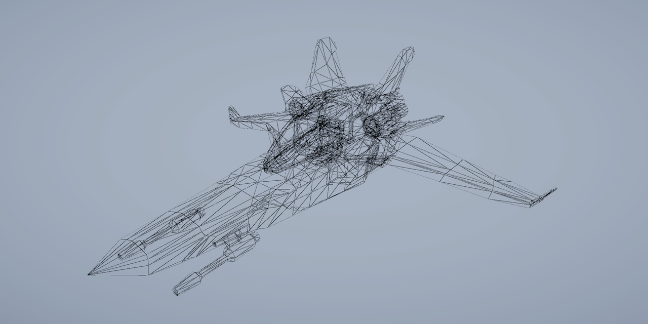
GitHub
A simple Shader Graph implementation of a wireframe effect. - GitHub - ArturoNereu/WireframeShaderGraph: A simple Shader Graph implementation of a wireframe effect.
what exactly does it mean? (For some reason i can't find anything regarding HLSL on google). numThreads is a const just above the numthreads parameter. This problem only poped up after a seemingly random change to the code inside the March kernel. I reverted those changed but the problem is still here

Why can't I supply two added normal maps into the normal map option???

It just wont accept
you need to use the LOD version of SampleTexture or whatever that node is called again
Normal maps typically go into the Normal port on the Fragment stage, not the Vertex one. (Unless you really want the values interpolated over the vertices)
True, I dont see a normal option in the fragment part though
It might not have one if the graph is unlit
Yeah, fixed!
Thanks
came back to shaders after a week and everything is all messed up now haha
appreciate the help though
one thing i noticed is that exact same const thread number variable works fine in another compute shader
Does anybody know of a variable/shader keyword that tells if we are in deferred rendering pass or forward. I can't use light tags. I'm in URP
If someone knows the answer to Chicho's question pls answer theirs first, but: in URP (shader graph) I'm trying to make a shader that tints the texture the color of the light the model is in. How would I get this lighting data?
I think you get that behaviour for free, don't you?
Well I mean; is there a node that will output the lighting data?
hello, i saw this video before https://www.youtube.com/watch?v=pmZQMzObjNo and i have a problem with the shader for the color

Thank you for subscribing. I worked really hard on this video so if you think that you learned something please hit that sub and like button. Share this video with your friends if you think it could help others. Also, join my discord where you get sneak peeks into the upcoming content and you can get help for anything related to unity. https://...
Using URP and 2022, Is there a way to shade a sprite in 3D where the back is black or another sprite? I searched for double sided shaders and didn't find much. Or, is there an easy way to make the back black without having a duplicate of the sprite as black? I use sorting scripts and it goes nuts when I tried that.

You can use the "Is Front Face" node in Shader Graph to conditionally shade the backface as black.
Ooo, thank you @low lichen! Just starting to get in to shaders and it's not going so well. haha I will get there. 😄
The combined output color of the Lit shader is not something you really have access to
I assume you'd have to calculate it yourself with the help of a custom lighting function
That said with URP Lit shaders lights do tint materials to to their color, no extra work required
Wireframe shaders usually use barycentric coordinates which you can't do with ShaderGraph unfortunately
https://www.youtube.com/watch?v=ehk8ljz2nHI This video series is pretty good

Here we provide several methods to create a wireframe outline from a mesh using shaders in Unity. We use the barycentric coordinate system to detect when we are near an edge in the fragment shader, and include some aliasing so we get nice crisp lines on our meshes.
The windmill model used is from the KayKit - Medieval Builder Pack. Available at...
Yeah I'm trying to mimic the appearance of an unlit shader (with absolutely no shadows or gradients across the mesh) but have it change tint based on surrounding light. Seems like a simple idea but I can't wrap my head around how to do it
I figure there's absolutely a way to do it with shaders but I'm having such a difficult time I'm considering making a system with colliders on light sources that change an unlit material's tint color
Should be relatively simple if you don't need to recreate any of the light shading
https://github.com/Cyanilux/URP_ShaderGraphCustomLighting
You can use these to get the light color and blend it with the base texture in an unlit shader
Might need to swap light direction to light position in the function instead
This seems like a great lead, thank you!

You rock, I'll try this out when I get home
Is there an issue with URP's full screen shaders and isometric / orthographic cameras right now? Got a shader graph solution that works in perspective but it breaks in orthographic views. Currently using Unity 2022.3.5f1 LTS.
.
Cyan deserves most of the credit tbqh, I'd be stuck without all their resources!
Does your shader rely on depth? That may be drastically different between perspective and ortho
YES
You should at least describe the issue, but your best bet might be to try to reach with your question whoever made that shader
I don't fully understand the differences, but I recall one of them might've been logarithmic and the other linear
Might be more to it though
Let me double check on the depth thing really quick tho.
If it was depth based removing depth from the requirements would cause it to break right?

In which case it does not in mine.
That probably refers to depth texture, which is just one of the types of depth shaders have access to
It's not a problem, it's more of a question if you can help me, the thing is that I don't know how to color the terrain
Yeah it's not related to the depth. Does orthographic views get the World Positions differently than the perspective view?
Trying to make it so that it only highlights around a radius around a position I can set.

Not that I know of
If you use Absolute World Position then I think that should eliminate any potential camera-relativity
Strange. I'm feeding this logic directly into my alpha and it should work, right?

I think even if Position node's World were camera-relative, I don't think any other position vector would be
So I'm pretty sure the Transform is not necessary
Hmmmm
Is there a way to reconstruct world space position from the screen position? On the other part of the shader, I use screen position to reconstruct normals to highlight certain slope angles and that does work with isometric perspective.
I recall the article I linked might've have something about exactly that
Sorry been running around, I missed the article! I'll take a look at that! 🤞
hello,
how to pass values to from fragment function to vert function in a fragment shader ?
basically, i just need to increase the y value at certain points
can't
how do you make waves then on y axis ?
by offseting it inside the vertex shader
yes i know but how to do that at a certain point ( at a certain pixel ) ?
no you just change the height per vertex using a sin wave of something and thats it you don't do anything with the pixel shader.
THANK YOU SO MUCH THIS HAS BEEN HELL FOR ME AND IT FINALLY WORKS NOW!
Awesome  Did there turn out to be a specific problem as the culprit?
The article nailed it, specifically with how the Position node currently doesn't work with isometric views with Full Screen Shaders. I had been attempting to approach it through mesh based approach instead of a blit one. In fact I had done the mesh approach prior. But the real helper was changing from position node to UV.
There also seems to be a lack of documentation on the new full screen shaders for URP but that's sorta to be expected since it's so recent? Still isn't fun to deal with lol
Hello! Does any1 know I can tile and offset a generated texture? For example, I am made a gradient, now I want to tile it in the uvs in a 4x4 texture. How can I do this?
I have though ran into a problem. I am trying to render masked objects with one material, and I used a different material and mask to occlude them when rendering because you could constantly view them even through objects. I tried rendering it with different settings and it gave me a weird output
the black box is in front of her but it's rendered in front of her

it works as intended when looking from the rectangles side, but on the character, it gets drawn first
and there is no real way (from what I have been trying) to render with depth testing so that the black recrangle is correctly rendered

here is the code
Does anyone know what I could do about it?
Hello! How can I Tile & Offset the lerp color result, in the same way the Rectangle Node or the Texture Sampler node offset their input?


Hi, more technical question here for the HLSL shaders. How to approach a shader that:
First, renders only backface depths and passes it to the next stage
Second, renders Front and Back faces, but discards the pixel if it's current depth is farther than depth from previous step
Essentially I'm asking how to pass some frame data, possibly from one pass to the next
I wouldn't have expected the official instructions to be so difficult to follow, especially compared to this custom way we've had for a while already
https://www.febucci.com/2022/05/custom-post-processing-in-urp/
This can be done with a two passes shader.
The first pass with Cull Front and ColorMask 0 (to render only depth, and not color), the second pass with Cull None to render back and front faces. The rest of the settings of the second pass should be good, as pixels with depth further away are discarded by default.
Oh, I think I need to give some more context, because I need some more control over that and I need to pass data between passes.
I wrote a raymarching shader, and I now I would like to add the pre-pass, which calculates front and backface depth and passes it to the next pass (I assume I could use IsFrontFace semantic to get in all done in one pass for both front and backfaces). What I imagine I would like to do, is pass a 2 channel texture calculated in this prepass where one channel is front face and second channel is backface depth.
As for why I need that, I want to calculate the ray origin and max ray distance from those values. My current shader renders renders in Geometry+1 queue without culling. This way I can draw a raymarched scene when I'm both outside of a mesh (front face is visible) and whenI'm inside the mesh (backface is visible)
The problem I'm trying to solve is that without it, there is no good universal way for me to limit the ray to the bounds of the mesh — my current ray origin is on the camera plane (there is also a toggle for it to start on a face, it's not on the face like in other raymarching tutorials, because it helps in drawing inside the mesh) but without this depth the ray can overshoot the back faces or appear "in front" of front faces
for example here is how it looks currently

the ray marches past the backface making it look like a scene from antichamber (ray origin above is set to start on the face)
and here it is when the ray origin is set to camera position

That seems pretty close to what we do in HDRP with advanced transparency buffer.
But you will need at least a screen space buffer to store the information from the first pass.
The shader itself is pretty simple : render both faces with an additive blending shader.
output positive depth for backface, and negative depth for frontface, you will end up with the thickness of the mesh.
Then, in the second pass, where you do your raymarching, you simply start for the current position and march through the stored depth
is the screen space buffer a shader concept, or do I need to write additional C# scripts for that?
You'll need to write addition c# scripts for it :/
and can you point me to soem documentation about it
damn :/
If you are using the bilt-in render pipeline, you can do it with a second camera, with a layermask to display only the needed object, rendering in a render texture (that would be the buffer), and using replacement shader : https://docs.unity3d.com/Manual/SL-ShaderReplacement.html
I also heard about things like "grab pass" or command buffers, could they possibly be used for that? I never investigated them further beyond hearing the name
seems like grab pass is only available in built-in, which is a bit of a shame, but for now I'm writing in built-in either way
"grab pass" probably won't help here, it is to grab the content of the screen that was rendered before, while you need some "other" data.
Command buffers would be a more clean way to set up and render the thickness buffer, but you can already prototype with my method.
oh, so grab pass is only invoked before once at the start, not "after a pass", is that correct?
Erm, I don't fully remember how it works, but iirc for every pass that requires a grabpass, the engine will do a dedicated pass before to store the screen content. Really not optimal :/
ok, thanks for your help :)
And as for why I wanted a shader-level concept is because I'm writing a shader generator and I wanted to avoid depending on any C# scripting for that, because I everytime a generated shader would be use, an additional script whould have to be added somewhere.
Hi, I have made this kind of shader. How can I edit the color in the background which is the white color? And to add an outline to my polygon shapes

quite a low resolution of that screenshot
Could multiply these together and then use the result to lerp to a color to change the background

Outlines are trickier since Polygon nodes strip out the UV information that we'd want to use for them
I think you could use a step or smoothstep on the Tiling and Offset result to get something like the polygon but with a configurable outline
I'd make one square with an outline like that and offset those multiple times, instead of making the shape multiple times
I think this is an excellent example of using 2D signed distance functions
Those would be useful as well
Or just do the whole thing with textures instead
2D SDF textures in particular would be both flexible and easy to use
Here are 2D primitives: https://iquilezles.org/articles/distfunctions2d/
To write a texture with a 2D signed distance function you would:
- for each pixel invoke
sdf_box(pixelPosition-boxPosition, boxSize, out color) - combine resulting distances with
min()to produce a "union" of boxes - output the color depending on the distance:
distance < 0means that it's the inside of the square,distance > 0means it's outside. If for example add custom color between for distance in0, .1you will have a roudned border outside of the square. If you color the border based on the0.9, 1you will have sharp corners border inside the square
hey guys, I'm a little confused with how the rotation works in shader graph, could anyone point me in the correct direction?
I'm not sure why it just changes colour when I try to apply a rotation? I'm not finding relevant info to tell me what I'm doing wrong here
My problem is that my texture has popped in at a different rotation to my actual terrain so it doesn't match, if I just rotate this 90 degrees, I should be good to move on

Rotation is a math function that operates on any vectors you give it
In this case you are giving it colors, so it "rotates" colors whatever that means
rotate about axis takes in a 3D vector, constructs a matrix from an axis and rotation, multiplies the vector by this matrix and produces rotated 3D vector. What you did was rotate the color in color space xd
You should be rotating UVs that you are mapping colors to
ok thanks, so what would be the appropriate node here?
the appropriate node would be inputting rotated UV coordinates to the sample 2D texture node

ok thanks I got a rotation working
Having a bit of weird issue when using Standard shader with transparent rendering mode! The left one is with opaque mode and right with transparent... as you can notice, part of the table mesh becomes almost entirely transparent.


Presumably your Alpha channel is set to black for those parts of the texture
I thought so too... but after inspecting the texture image the alpha seems to be 1 throughout.
Or if not the texture, the alpha of the vertex colour
AFAIK the standard shader doesn't use any vertex coloring, so I ruled that one out
and indeed with my simple transparent vert/frag shader the results are same. So I am guessing if it might have anything to do with render order?
Maybe something else is writing to the depth buffer between the opaque rendering and when this occurs?
Take a look with the render debugger or renderdoc perhaps
This is the only mesh in scene at the moment... so I would think the depth buffer should be clear.
I can't really tell what I'm looking at but is the mesh inverted?
There isn't much of a reliable way to do transparency sorting of polygons within a mesh
They are sorted by their winding order
This is a lidar scanned mesh from iphone. Also on Mac so sadly can't use RenderDoc... Frame debugger isn't helpful either I guess... unless there's anything specific I should look for?
You'd probably want to split the furniture into their own objects so you can benefit from per-mesh transparency sorting properly
https://pastebin.com/pUNEuLLi
Anyone know why my renderer feature causes this issue? I just copied the code from a tutorial and it worked fine in his unity. If I use Full Screen Pass Renderer Feature and throw my material in, nothing happens. If I throw the FullscreenInvertColors in my renderer feature, the issue in the screenshot occurs. I'm quite confused :/

Pastebin
Pastebin.com is the number one paste tool since 2002. Pastebin is a website where you can store text online for a set period of time.
btw the texture variable name matches with that in renderer pass

Make sure this a Fullscreen Graph, and use _BlitTexture reference or the URP Sample Buffer node to obtain the blit source instead. Then it should work with the Fullscreen Pass Render Feature.
If you want to stick to your own feature, I'd use RenderingUtils.ReAllocateIfNeeded instead of the RTHandles.Alloc with a RenderTargetIdentifier, (then cmd.GetTemporaryRT and the .Release(); is also not needed - well, you should release but in dispose rather than every frame afaik). I have some example code here - https://www.cyanilux.com/tutorials/custom-renderer-features/#rthandle
https://pastebin.com/ZFPUQDvz
I just modified my code according what you said and recreated a full screen shader graph. This time, the material works fine in Fullscreen Pass Renderer Feature, but still not in my custom one. It seems that the shader only affects objects in scene. Also, exception occurs when I click on those objects

Pastebin
Pastebin.com is the number one paste tool since 2002. Pastebin is a website where you can store text online for a set period of time.
So, if I want to use blit texture in shader graph, I need to create a urp sample buffer node, and if in shader code, I need to include Blit and use _BlitTexture. If I want to set buffer to my own variable like _TempTex, I need to set that texture in renderer feature script. Am I right?
Yes
The error seems to mention one of the targets used in the blit is null/unallocated. You have the ReAllocateIfNeeded in Execute but I usually see it in OnCameraSetup so I'd try it there.
I'd also add if (renderingData.cameraData.isPreviewCamera) return; in AddRenderPasses to avoid the feature being used for item thumbnails / preview editors in inspector as I've seen those cause errors sometimes.
If the fullscreen one works can just use that though. Or look at it's code as an example : https://github.com/Unity-Technologies/Graphics/blob/master/Packages/com.unity.render-pipelines.universal/Runtime/RendererFeatures/FullScreenPassRendererFeature.cs
The exception disappeared after adding if and the shader affects fullscreen after I changing RenderPassEvent! Thanks for your help!
About this ball under my model: If its rgb values are (0.4, 6, 6), it glows. It has a 1-fresnel effect with gradient to make it toony
its color gets multiplied each stage 1, .66 and .33 so its first stage is (0.4, 6, 6) second stage is (.24, 3.6, 3.6)
when a color is > 1 making it bigger doesn't affect the visible color, it changes the glow on bloom though.
so at its first stage its visible color without bloom was (0.4, 1 , 1) and at its second stage its (.24, 1, 1) only red color changes visibly
i can't make this glow because of that, as it kinda ruins the thing.
its even more visible if its (6,6,6) then its visibly %100 white at every stage
main colors range should be 0-1 for this to work which means i cant make it glow without seperate bloom and main colors

this is when its color is (0.4, 1, 1)
it doesn't glow
when i make its color (8, 8, 8) it does glow but loses its phases

how can i make this work while glowing
is there a way to have separate bloom and main color
this is generally happening, i have to make somethings color > 1 for it to glow
i managed to make it work (kind of) like this by having values like (0.4 , 8, 8) but is there a better way?
This is how bloom works. It's reproducing the glow you see in cameras when the sensor is overwhelmed by bright light.
You can decrease the bloom threshold to be less than 1, but this will lead to a muddy looking picture, like back when old games used bloom without HDR, where they couldn't use colors brighter than 1.

Bloom uses the intensity of the pixels to control the glow. If you want to separate these two, you need a custom post processing effect.
i guess i would need to make some kind of bloom-buffer and draw different colors there
that probably means no other game actually needed something like this though
Some games use the alpha channel for this. Beat Saber comes to mind.
Yes.
oh wait that would be great
can alpha be > 1
i guess i need to make it betwen 0-1
thanks for the help
Depends on what render texture format you're rendering to.
than i will try to make my own bloom and make it work with alpha channel
i was using it for transparency but if i multiply alpha with color after passing it to bloom
i hope it'll work
Mmm, it's tough to make that work with transparency. I've done this for a custom bloom effect, and for transparent objects I generally disabled alpha writing with ColorMask RGB in the shader.
This disabled all bloom on transparent materials, but that was better than the alternative: max bloom on the opaque parts of transparent materials.
i make some pixels have 0 transparency too
i hope it wont create problems
i render like this first

dithered
Alpha clipped?
So you render sprite twice, once as opaque, but dithered, and then as transparent on top of that?
this is the pixelization method on elliot bentine article
i don't know much about it either but
i render dithered
than a post processing effect
fills the empty pixels with adjacent ones
Oh okay, interesting. That should work fine then.
thanks for the help
@humble robin it sounds like you want to quantize the bloom - the easiest option would be to render it, bloom, and then apply color grading in post processing to quantize the color in screen space
you could also fake the effect, similar to a lens flare, by rendering something over the top which provides the bloom effect and is quantized
Color grading works! Also, your article really helped me so much! Your method for pixelization is really the best one I found. Thanks a lot for helping
check your messages too
Hello, I created a shader graph but I'm having some issues.
In the editor, the images appear correctly, but in the game, there's a strange black outline.
Game:

Scene:

Shader:

The texture appears in a strange manner in the shader as well.
Texture Settings:

Does anyone know what might be causing this issue?
How do i integrate CanvasGroup alpha on Ui shader?
Yeah, it's a sprite
Should I change the texture type?
No, you could change the shadergraph material
but then it might not work on your canvas
On Unlit:

Only changed the material type to unlit
what could cause my shader material making sprites appear on top of everything without respecting layers
Solved my problem using round on alpha
where canvasgroup pass alpha to images?
For sure. I'm not sure if it's me but I've felt like recently the documentation has been a little lack luster but I may be wrong.
Hi guys

i am unable to achieve this much noise detail in Unity, how can i do that?

i am getting detail like this
this is Shader node setup i am using


I have to import it in unity as a texture file then?
Someone made a custom node for it https://github.com/sergiobd/FractalNoise

GitHub
A shader graph port of fractal noise. Contribute to sergiobd/FractalNoise development by creating an account on GitHub.
i hope this is mobile optimized
what do you suggest, should i try it for mobile setup or go with Imported texture?
Oof mobile?
For mobile, textures are usually recommended over procedural methods
^^^^
You targeting a normal mobile device or oculus quest?
Got it, i was using Procedural Setup to Avoid the Texture tearing and repeating and using Noise to generated distorted pattern
I have to ask my Developer about this, but i think he would prefer normal device as well
https://www.youtube.com/watch?v=hXYOlXVRRL8&ab_channel=Unity
finally, something useful

Let’s get our heads in the clouds! In this tutorial, you’ll learn how to construct a cloud in Unity in three stages.
If you want to follow along with this video, download the project from GitHub: https://github.com/NikLever/Unity-URP-Cookbook
This tutorial comes from a recipe featured in our "Recipes for popular visual effects using the Unive...
i mean you can bake the noise if you really want to be optimize, but i thing for mobile better to use the texture instead the generated one
Could any body have make this kind of shader?
This is a a cell and a virus of agar.io.
Their bodies are not hard. They are soft bodies.
Normally they have jelly outlines.
When they overlap, they look like this.
Does somebody have experience of making this?

And I have another question
I made a grid map like above using shader
But there was an aliasing
I think I can remove the aliasing using anti-aliasing feature of URP project template
Could you share me a tutorial to do this?
If you want a legit soft body you’ll need a simulation engine like liquidfun. Unity’s engine is actually compatible with that but I don’t think it’s natively implemented.
However here since there isn’t really any physics interaction needed you can get away with tricks
For example, you can use collision triggers to determine which cells are in contact, and then use that information to calculate the overlap points, then draw the objects accordingly
Thank you for you kind explanation
Is it possible to write a shader to render the SDF of a given texture?

Input < and output >
yeah just Blit the texture using a fullscreen triangle or quad and calculate your sdf in that shader
Take a look at signed distance fields, they could work well for this
it reminds me of things like 'metaballs'
this article does essentially what you are after using a jump flood algorithm https://bgolus.medium.com/the-quest-for-very-wide-outlines-ba82ed442cd9
it then uses that SDF to create the outline - but the original base texture the sdf is created from is an arbitrary binary mask like your first texture
Not particularly related to shaders
They are generative geometry skinned onto a ring of control points which have spring and collision simulation
https://youtu.be/3OmkehAJoyo A simpler version of this basically
struct Varyings
{
    float4 positionCS : SV_POSITION;
    float2 texcoord   : TEXCOORD0;
    UNITY_VERTEX_OUTPUT_STEREO
};
What is positionCS here refers to? It's in Blit.hlsl which is for post-processing and I don't know what does positionCS mean to a pixel. Or can I use this positionCS to reconstruct world position?
If I transform this positionCS to positionWS using ComputeWorldSpacePosition(IN.positionCS,UNITY_MATRIX_I_VP) and output the result directly to screen, why I the colors change as I changing view direction?
Thank you I will try once
There are hundreds of thousands of cells and viruses and pellets on playground
I don't think they are all softbodies with physics and collisions and springs
Thank you
the "CS" is certainly for "clip space".
Whose clip space? I don't understand why a pixel has clip space.
There obviously is heavy simplification and optimization but that's the principle behind it
Moving to #⚛️┃physics
https://learnopengl.com/Getting-started/Coordinate-Systems
You can represent the clip space as the camera frustum with coordinates ranging from -1 to 1 in all axes
Okay Let me try once
As the clip space starts at the camera near plan, I expect the positions values to change when you rotate the view.
Yes. So what does the result of ComputeWorldSpacePosition(float4 positionCS, float4x4 invViewProjMatrix) mean? The world position of what? I made a water shader a few days ago, and I also use this function to calculate the position of river bed below water surface and use that position to sample caustics texture. What's the difference between the world space in post-processing and that water shader?
Probably the biggest difference is the projection matrix. In a post process, there isn't any projection required, so I'm not sure of what the matrix value would be at that point.
To compute the river bed position, didn't you use this variant of the function that needs depth ? https://github.com/Unity-Technologies/Graphics/blob/master/Packages/com.unity.render-pipelines.core/ShaderLibrary/Common.hlsl#L1327
Yes I used that one. So I have to use that variant in post-processing?
To retreave the world position of the pixel from the depth buffer, yes.
Ok, problem solved, thanks for your help
Anyone know how I would go about writing shader code for something like this/any resources that may help?

Most toon shaders could be customized to have that kind of color gradient, and you'll probably also want to implement normal mapping
I'm guessing you mean normal mapping to get the smooth appearance without excessive geometry yeah?
Yes
Not smooth appearance exactly but to express all the surface details of the shapes
you might wanna look at this channel he explains a bunch of different filtering techniques to get some very interesting stylized results like that and a lot more throughout the channel:
https://www.youtube.com/watch?v=5EuYKEvugLU
I'm rendering a displacement map but the texture isn't cleared properly each frame as demonstrated in this gif. Any idea why this is happening?

My camera's background type is an opaque black color. Post processing is disabled in the custom frame settings

And this is the render texture

HDRP?
yes 👍
This feels like something that should be done purely in code with a CommandBuffer. There's a lot of extra stuff happening in HDRP when rendering a camera.
Custom Render Textures can also serve this purpose, but I prefer to do it code.
Ok I will look into that, thanks. I'm a lil rusty with the srp apis - when you're referring to rendering via a command buffer would that be through a custom pass volume, or is there a different way?
You can execute a command buffer anywhere, with Graphics.ExecuteCommandBuffer. And technically, you don't need to use a CommandBuffer for this, you can use the methods in Graphics directly, like Graphics.Blit. It's only if you need access to data from the SRP or hook into a specific point during rendering where you need to use APIs like custom passes.
Super cool! Thanks again for the info 🙏
Also fwiw I just found that changing the rendering pass of my displacement mat to After Post-Process seems to have fixed the issue. I have no idea why I'd need to do that when post processing was disabled on the camera and its volume mask is set to Nothing. Oh well 🤷♂️

TAA ghosting 🤢
Even with post aa disabled on the camera!?
Hey people, I'm wondering where to look to really learn about coding shaders
but more specifically how would something like saturation over distance work?
Like in this kind of image where the mountains slowly get more desaturated

getting this weird texture cut up effect when exporting from blender. not sure if its a shader issue
has anyone experienced this?

check the normals of your faces, I suspect your chain link is one polygon thick and you've got random triangles facing inside or outside
if so, use a two-sided material or model duplicate faces with normals inside and outside
(if you look from the other side, do you see the inverse?)
retrieve depth buffer and saturate the pixel which are further in the distance. If you like to get into shaders in unity you have the option to choose from shader graf and normal hlsl coding I would go with hlsl and I think a decent place to start is freya holmier on youtube and catlikecoding as well
Is there an easy way to make an outline shader in HDRP just for highlighting some objects, i tried some tutorials but nothing really worked for me.
a crappy one sure, an actually good one, that takes more effort.
"In real open-air scenes, when a target object viewed by an observer is far, the perceived object’s appearance changes,
being fainted and blended to the environmental light color. This natural effect is known as aerial perspective
and is due to the light scattering by particles suspended in the atmosphere": https://www.cvl.iis.u-tokyo.ac.jp/data/uploads/papers/Carlos_AerialPerspective_CVA2017.pdf, https://sebh.github.io/publications/egsr2020.pdf
isn't this basically just the "fog" postprocessing effect?
For some reason I keep getting this error Output value 'frag' is not completely initialized
Pastebin
Pastebin.com is the number one paste tool since 2002. Pastebin is a website where you can store text online for a set period of time.
not sure whats causing it
whats causing this error
nvm just figured it out
Is it possible to write multiple fragments in one pass? I wanted to perform an operation on groups of 8x8 pixels without needing to re-compute the effect for each of those pixels
I dont think so
Damn, so it's down to writing deterministic code to do this as fast as possible?
Im not 100 percent sure but from what ive seen you can only have one output value
Does anyone know how to make a fragment shader receive shadows?
Cause doing this TRANSFER_SHADOW(o) just causes an error