#archived-shaders
1 messages · Page 55 of 1
what if I just use the bounding box

its close enough for most shapes, I just need to hack this apart to get it done, perfect is obviously not going to happen
That what I suggested before, use the world bounds, but you were not happy with the result
Yeah because I thought this would be easy
but since its not easy, I have to give up being happy and just get something done because something is better than me spending another 7 hours doing jack shit
result = (worldPosition.y - min.y) / (max.y - min.y)
is this not that? because this didnt produce that for me
It didn't produce what ?
I've only seend the graph preview, not scene screenshot
I'm pretty certain that it works

this right here is a value of "3"
it should be a value between 0 and 1
so its not usable as is

oh im a fucking idiot again as usual, im using the old bounds and not the ones from Object
pebcak can't do a single @#$@^ing thing without @#$@^ing it up
its so immensely frustrating to be stupid
but there is nothing I can do to become not stupid
yep works perfectly when I plug in the actual min max
Don't freak out for any error that you hit, stay calm and learn from it.
Yeah that'd be the healthy reaction
okay unstuck its working moving on from this instead of losing my shit for the next 7 hours
not sure if this is the right channel but does anyone know how to use projectors to display a decal
Right channel this is not
Nobody can advise you unless they know what render pipeline you're using
Projectors are kind of inherent to displaying decals so the question is unclear
oh right 🤦♂️ i won't go into more detail without being in the right channel, would you kindly direct me?
im using the built in pipeline
can you think of any reason why bounds min max might break based on camera rotation/position?

nothing in here relates to camera so I don't get why its doing this


For that I don't think there is any channel that exactly fits this topic
So that might leave you with just #💻┃unity-talk
hm yeah thats not good 
oh i see... thanks anyways
Try and isolate what's changing as you move the camera, for example, try omitting the smoothstep entirely and plug the output of the split node into the alpha, then see if anything changes as you move maybe
Not sure exactly what might be happening there, but it usually helps to isolate the problem as much as possible
Guys i need help with something very rudimentary ------> https://forum.unity.com/threads/blitting-from-one-rendertexture-to-another-with-identical-settings-turns-colors-to-grayscale.1465985/

Unity Forum
I have a texture that i blit to a RenderTexture and it displays correctly (blue,green,red,yellow etc.). But when i blit that RenderTexture to another...
Have you been changing the bounds of the mesh or renderer through script?
as far as I can tell the problem is these two values, when I remove them from the shader, it no longer 'turns off' based on position

Is this in URP?
Yes, and I am also not changing the bounds through renderer or script
turns 'off' when bounds min / max are used, doesnt when they arent (pictured)

I can only guess there is something wtf about these two values?

keep in mind those bounds are in world space, I'm thinking something's getting werid when you get negative numbers
I'm not sure though, that still doesn't explain why camera position changes anything
moving the object also breaks it it seems
how can I figure out if the problem is world space negatives?

Not sure, I was just thinking it might cause an issue, should be totally ruled out if you move the object so that it's bounds are fully in the positive y space
Are you using HDRP perchance?


1 : What happens if you use "absolute world" in the position node ?
2 : and if the shader is set to opaque with alpha cutoff ?
my only guess is somehow a divide by zero is occuring?
ill try both that
absolute world changes nothing, alpha clip I cant get it to mask a all no matter what value I pass in

how does alpha clip work, no matter what values I pass in it never clips
Hmm
Isolating it even further, try outputing just the world bounds min or max individually, and see if they flicker around
Don't you have an alpha output connection when using alpha clip ???
min and max are both pure white with no flicker

Could you try using Bounds Size instead of subtracting min and max?
They're probably being pushed far into HDR because the values are above one, try using a remap node to map from somewhere around the Y position of your object to a 0-1 space
or, actually come to think of it you could probably just move the object itself to y 0
That should make it visible
😐 well it stopped happening, which isnt helpful because I didnt change a single thing and it stopped happening all on its own
@tight phoenix You should have alpha and alpha clipt threshold.
Connect the result of divide.Y to alpha, and set clip to 0.5, it should cut the shape in half

Always a reassuring sign.
Graphics programming Is just kind of like that
no matter what I feed into alpha clip, it never masks
Did you enable it in the graph settings ?
I did
I can no longer reproduce the bug
nothing I do is making it come back, not that I want it to come back
but I dont know why it stopped 😬
you'll hear from me again if/when it returns I guess???
oh its happening again
I moved it closer to world 0
and it resumed happening
its gotta be divide by 0 happening right?

Juging from this screenshot, you've manually added the alpha clip threshold output block without enabling the feature in the graph settings, so it is ignored (and grayed out).

Unless the object is scaled to 0, min and max bounds should always be different
I hit this checkmark
is there more to do than hitting this checkmark
that is what caused alpha clip to appear
no matter what I pump into alpha or alpha clip threshold, nothing masks if that checkmark is on
Ok, so that's good.
And this setup give no masking ? Could you again show the connections ?


current graph, current output gif
notice preview is pink - which is why I keep saying I think divide by 0 is happening
Don't use the smoothstep in this setup, just the Y from the split node plz

This is just because the object node's values are not great at all
no change from the above gif
Ahh gotcha
Hey, surface type is still transparent here
uh further wtf, moving a different object with the same shader on it is flickering different OTHER objects

okay no transparency now, opaque with alpha clip
Still bugish ?
Flicker appears to have stopped
which is nice but also I kinda wanted it to be transparent
wait hold on

the flicker is still happening even with alpha clip, except its flickering the entire mesh
is the problem maybe that min max bounds are updating due to the masking?
and so like, the range im masking is constantly changing due to the min and max physically change as more of it becomes fully not opaque?
They are not
oh okay
well then in that case I have no answers or thoughts, but the flicker is not happening visually to the fragment but IS happening to the orange unity selection box, when in alpha clip
I wouldn't be surprised that the selection outline doesn't like alpha clip fronm shadergraph
Do you still have the local bounds script active and setting values ? If yes, could you remove it ?
its been removed a while back, and the values arent getting used anywhere in the shader, I can delete the parameters entirely maybe

the selection highlight is acting super bizarrely
I don't get why the flickering is happening, it's dead stable on my side whe I try
Am on .21
even weirder still

these meshes, I cant even click on them when the 'flicker' is removing the outline
clickable now, but if I move the camera, I cant select click them

gif explination:

Im starting to think unity itself is doing something wtf and its not my shader 👀
🤷
Like I said, I would no be surprised if the scene picking pass has troubles with the alpha clip
the flicker does not occur if the bounds min max are not used

so Im 100% sure those are somehow the cause
since removing them it stops happening
Try upgrading, like I said it worked on my side.
Else, maybe the property block is interfering in some way
currently there is no property block happening, I removed all those scripts and parameters
Ill update unity version to 2022.3.5f1
and see if that helps
relaunching now - in the mean time do you think its possible that the problem is that multiple meshes are using the same material and same shader?
so all their different bounds are somehow causing it to asplode?
It should not, but it can be :/
what setting would I have to change so this material isnt so bold. there are no reflectioons even when a directional light is pointed at it, im changing all the rgba settings and the colour changes but the a value doesnt change anything. any help would be appreciated thanks


Is this an unlit material ?
in your scene did you test with one single mesh or a bunch? Try spawning a bunch of differenty unity primitives witth different rotation, scale, positions maybe? To see if it causes the bug
I tried with about 5 different meshes in the scene
yeah unlit material
Well, unlit by definition doesn't react to lighting ...
oh crap i didnt realise thats what it meant. i thought it meant it didnt emit light, sorry my bad im dumb
Would it be possible to simulate a Lit Shader in an Unlit Shader? Like, get shadow data and such. I'm wanting to modify shadows
I'm trying to use this Triplanar node in Shader Graph to have a texture appear on vertical surfaces and side surfaces, but I wanted them to clamp so that there is no blending between them (switching between textures at the 90 degree angle). Is there a way to do this?

Never used it, but I assume you'd have to change "Blend"
With very high blend values (like 100 or 1000) the transition between textures is very sharp, though not absolutely
It uses a power function for the blend, so if you don't want that you'll have to implement your own triplanar mapping that doesn't use it
But is there a way to have three different textures feed into that texture node?
GitHub
Some custom lighting functions/sub-graphs for Shader Graph, Universal Render Pipeline - GitHub - Cyanilux/URP_ShaderGraphCustomLighting: Some custom lighting functions/sub-graphs for Shader Graph, ...
I've did that in my nodes library : https://github.com/RemyUnity/sg-node-library
Sorry, almost no documentation, but this is what you are looking for :


@amber saffron i fixed the colors on the rendertexture going to grayscale during the blitting but i still have the original problem. i find the heighest point at different uvs. then if the result is more than .7 i output a red pixel. If its less i output a green pixel. So youd expect all the colors to be either red or green. But theyre red AND green.
Can you share the code here ?
Copy paste the code here with code quotes ( this one : `)
3 quotes to start the block, 3 to end it, and you can add a langauge for highlighting

                    bool brushTouchingOutputPixel = false;
                    float greatestHeightAtSpotLocations = -1;
                    for (int index = 0; index < 9; index++)
                    {
                        half2 diff = _ArrayCoordinatesOfSplats[index].xy - i.uv;
                        half2 scaledDiff = diff * half2(_SizeX, _SizeY);
                        if (abs(scaledDiff.x) < 0.5 && abs(scaledDiff.y) < 0.5)
                        {
                            float heightOfDisplacementMapAtSplatPosition = tex2D(_MainTex, _ArrayCoordinatesOfSplats[index].xy).r;
                            if (heightOfDisplacementMapAtSplatPosition > greatestHeightAtSpotLocations)
                            {
                                greatestHeightAtSpotLocations = heightOfDisplacementMapAtSplatPosition;
                            }
                            brushTouchingOutputPixel = true;
                        }
                    }

                    if (brushTouchingOutputPixel)
                    {
                        if (greatestHeightAtSpotLocations < 0.7f)
                        {
                            return float4(0, 1, 0, 1);
                        }
                        else
                        {
                            return float4(1, 0, 0, 1);
                        }
                    }
                    else
                    {
                        return heightOfDisplacementMapAtOutputPixel;
                    }
Hum, yes, I'm lost, I don't see anything here that could explain having different values
was in a meeting, testing this now on the new version
flicker still happens on latest, no change
I'm out of ideas
same
Im going to just try to achieve what I want but without using the bounds calculations
fudge it some other way
@rough hawk Don't cross-post. Stick to one channel, please.
Sorry guys, I just joined. which channel would best fit my question.
You've already asked in one channel. Wait for answers, if it gets buried you can repost after a reasonable amount of time in another channel you might think is relevant as well.
@amber saffron emy i wonder if i should use GPU instancing to pass the decal UV coords to the shader?
🤷
can anyone help me here, i have no clue what this means or how to fix it

You didn't assign a .hlsl file in the Source field
alright i presume i have to assign the one that my project is under?
Yes
@amber saffron i think i found a solution. Im going to output the highest displacement value to a 1x1 texture and use that as input to another shader that will alter the entire 4096x4096 map.
Hey Folks! I have a question. What is the difference between #define and #pragma shader_feature KEYWORD. my understanding is they do same thing, define a keyword that can be used for if else and static branching
you can't turn off and on #define I think? #define is more like specific pass maybe, but shader_feature is more like if you want to use specific shader feature or not
there is also #multicompile thingy
Hey! I've been having some weird artifacts and bugs relating to this one ToonShader in my project. I was wondering if anyone would be able to maybe identify what sort of issue this is or what could be causing it? I don't really know how to explain it, so here's a video of it in motion.
As you can see, the geometry in this video stops receiving shadows and starts to weirdly display other objects in the area when viewed at a certain angle. I don't know what the reason for this is. If it helps at all, here's the shader file:
Yeah there are lots of these things that I don't completely understand
 I noticed I am making a lot of derivatives of the same basic shader, each of these is like 90% identical, what is the best/most optimal workflow to reduce duplicate code / lower how much work it is to maintain branches?
a copious number of Subgraphs are the first thing that comes to mind, but is there anything better than / in additon to that?

most of the same pieces, the same inputs, is there some way to make like, a derivative shader that inhereits all this instead of remaking it over and over?

highlight the consistent sections of your shader graph. Right click a blank area and select convert to ->subgraph. You'll be able to rename all you inputs and stuff- just like a function. You can then add this subgraph, as a single node, to any other graph.
oh, sorry.. nm.. you got that already
Yeah I know about subgraphs, I even mentioned it in the post itself, I was wondering if there was more I could be doing than that, yeah
googling it looks like subgraphs is all there is really, inhereitance isnt really a thing
That's all I know of:( the backend HLSL, is c not c++, so yeah, would be hard for 'em to do (inheritance).
I'm just starting out with compute shaders- hope it's ok to post Q's on em here...
I want to use a compute shader to progressively alter a texture. Meaning each cycle, the change to the texture depends on the current state of the texture.
Do I need to have separate read and write version of the texture? (And if so, how do I copy the results back into the "read" texture at the end of each compute shader cycle? I want to use this texture in another shader (shader-graph for drawing).
I ask because I'm running into some odd issues: this version of my test shader graph code works fine, and changes both texture to red (as seen in the inspector)
// The two input textures that we want to adjust.
RWTexture2D<float4> _GroundTexture;
RWTexture2D<float4> _WaterTexture;


[numthreads(8, 8, 1)]
void RedTest(uint3 id : SV_DispatchThreadID)
{
    // Store the color red in a float4 variable.
    float4 redColor = float4(1, 0.0, 0.0, 1);

    // Write the red color to both input textures at the current pixel.
    _GroundTexture[id.xy] = redColor;
    _WaterTexture[id.xy] = redColor;

}```

But THIS code, sets both texture to black!
```#pragma kernel RedTest

// The two input textures that we want to adjust.
RWTexture2D<float4> _GroundTexture;
RWTexture2D<float4> _WaterTexture;


[numthreads(8, 8, 1)]
void RedTest(uint3 id : SV_DispatchThreadID)
{
    // Store the color red in a float4 variable.
    float4 redColor = float4(1, 0.0, 0.0, 1);

    // Write the red color to both input textures at the current pixel.
    _GroundTexture[id.xy] += redColor;
    _WaterTexture[id.xy] += redColor;

}```and THIS code leaves _GroundTexture intact (with an image I copied in there at startup), WaterTexture starts and remains black:
// The two input textures that we want to adjust.
RWTexture2D<float4> _GroundTexture;
RWTexture2D<float4> _WaterTexture;


[numthreads(8, 8, 1)]
void RedTest(uint3 id : SV_DispatchThreadID)
{
    // Store the color red in a float4 variable.
    float4 redColor = float4(1, 0.0, 0.0, 1);

    // Write the red color to both input textures at the current pixel.
    ///_GroundTexture[id.xy] += redColor;
    _WaterTexture[id.xy] += redColor;

}```Made this scanline + RGB Effect shader, wanted some opinions

hey is it possible to get the return of float4x3 function float4x3 GetValue() stored on 4 seperated float4 without having to store the return of the function on a float4x3 first ?
i was thinking of float3 f1,f2,f3,f4 = GetValue();
where f1 = GetValue()[0]
This might be helpful reading:
https://learn.microsoft.com/en-us/windows/win32/direct3dhlsl/dx-graphics-hlsl-per-component-math#the-matrix-type
With HLSL, you can program shaders at an algorithm level.
one example from there:
// Given
float2x2 fMatrix = { 1.0f, 1.1f, // row 1
                     2.0f, 2.1f  // row 2
                   };
float2 temp;

temp = fMatrix._m00_m11 // valid
temp = fMatrix._m11_m00 // valid
temp = fMatrix._11_22   // valid
temp = fMatrix._22_11 // valid```its thanks for sharing but that is similar to what i have right now ,
i first store the resturn on float4x3 results then distribute it on the other float3 variables, my question is , is it possible to just distribute it right away without having to store the variable first ?
like this float3 f1,f2,f3,f4 = GetValue();
ok thats all i wanted to know , thanks ❤️ ❤️
You would want two textures normally, because the driver can't guarantee what order memory accesseses happen in. But in the case of a compute shader, you can use a memory barrier in between the read and the write operation and it should work fine
can I use the #if like this to remove a function?
#if defined(_OCCLUSION_MAP)
    float GetOcclusion (Interpolators i)
    {
        return lerp(1, tex2D(_OcclusionMap, i.uv.xy).g, _OcclusionStrength);
    }
#endif
or it need to be inside the function like this?
    float GetOcclusion (Interpolators i)
    {
#if defined(_OCCLUSION_MAP)
        return lerp(1, tex2D(_OcclusionMap, i.uv.xy).g, _OcclusionStrength);
#else
        return 1;
#endif
    }
You can use the first one, but then of course you'll get an error if you try to call the non-existing function from somewhere else
I see thanks Nitku
better or cleaner way to write this?
float4 OutlineFragmentProgram(Interpolators i
#if defined(LOD_FADE_CROSSFADE)
    , UNITY_VPOS_TYPE vpos : VPOS
#endif
    ) : SV_Target
{
    // code
}
is there like inline #if defined()?
nope
for clarity I'd do
#if defined(LOD_FADE_CROSSFADE)
float4 OutlineFragmentProgram(Interpolators i, UNITY_VPOS_TYPE vpos : VPOS) : SV_Target
#else
float4 OutlineFragmentProgram(Interpolators i) : SV_Target
#endif
{
oh! thanks Nitku!
can you like turn off and on double sided from custom GUI?
Pass
{
    Tags
    {
        "LightMode" = "ForwardBase"
    }

    Blend [_SrcBlend] [_DstBlend]
    ZWrite [_ZWrite]

    CGPROGRAM

    #pragma target 3.0
    #pragma shader_feature _DOUBLE_SIDED

    #if defined(_DOUBLE_SIDED)
    Cull Off
    #endif
        // code
}
but it say

Cull needs to be outside of CGPROGRAM, it's ShaderLab not HLSL.
Like the Blend/ZWrite you already have, you can use properties to define the value :
// in Properties :
[Enum(UnityEngine.Rendering.CullMode)] _Cull ("Cull", Float) = 2 // "Back"
// in Pass :
Cull [_Cull]
thanks!
it's 2 sided now, but it's only doing cutoff on one side, anyone know how to cutoff both side?


is there a away to flip a face in fragment shader?
not normal flip, but like the face itself
At pixel shader level there are no faces/triamgles/geometry anymore. Just pixels. Cutoff is not bound to sides. Can you show full source code of your shader?
it's lots of code, I have 4 .cginc, since it's support reflection, normal map, etc
but what I want is just a way to make my leaf transparent on both side
do you know how to make like cutoff shader that is double sided?
It should already clip both sides
Cull off, and discard in pixel shader
but it didn't for me, like look at my screenshot there
Can you show portion of code where your alpha test is performed (clip or discard)?
Hard to say why without seeing the code, but check what calculations you're doing for the clipping. Unless you're using SV_IsFrontFace (or VFACE) I don't really see why it can be different per side.
Is the alpha based on normal vector perhaps?
Pastebin
Pastebin.com is the number one paste tool since 2002. Pastebin is a website where you can store text online for a set period of time.
no It's based on MainTex alpha
Then it shouldn't be different. Perhaps what you're seeing is a different pass/object?
ah... let me try removing my other pass...
ah... it's my other pass... 
thanks guys I found the problem
so we have #shader_feature to remove and adding a code on compile time. Can we do something like adding and removing a pass?
It is not possible. You need two separate shader files with common code in include files.
I don't know but an empty (no shaders, no setup) pass is an invalid pass. So I assume it will be just ignored.
oh! thanks I will try to look into that
Material.SetShaderPassEnabled anyone have tried this?
this function is a scam 
So... I've built a voxel engine thats pretty robust and handles beveled edges but i'm looking for ways to distinguish the different block types.
Each block has its own material and I was wanting the materials to generate small geometry details like pebbles on the dirt blocks.
Would I want to use a vertex shader or something for that? I havent messed with shader programming but would like to learn

Right now I'm kind of wanting to work without generating UVs because the mesh was a lot more complex to generate than meets the eye,
especially with how the corners blend in all directions
My idea is to do something similar to grass and create a bunch of vertices in a range around the player as they move, placed on the appropriate block type.
So dirt might have pebbles on all sides while grass only places those vertices on top
Most performant, but most technically demanding way is to use tessellation. With it you can progressively make geometric details on your cubes without hurting overall performance.
I have a question. Does the Unity Toon Shader support Global Illumination backed lighting? Because everytime I try to back lighting the sceen goes completely black, but lightmaps are created so it seems to be working, but it isn't. But if I use a normal normal URP shader it works fine.
It needs to be implemented in the shader, such as with Baked GI node
Oh ok. Problem with that is Unity only provided the HLSL for the shader and not a shader graph file. Unless I'm missing something.
vertex shaders cannot create new vertices. If you want small "raised" looking bumps, you're looking more at a technique called "bump mapping" or "heightmap"
basically you deform the normals at the fragment level based on a texture to create imaginary bumps
I see, i'd like to actually create vertices so may just do manual mesh generation stuff
Didn’t read particularly tis, but looks good and detailed: https://nedmakesgames.medium.com/mastering-tessellation-shaders-and-their-many-uses-in-unity-9caeb760150e
Medium
I’m Ned, and I make games! In this Unity graphics programming tutorial, I’ll introduce tessellation shaders and show many ways to use them!
Tessellation will generate vertices for you
I have question about Shader Graph.
I want Shader Material attached to object(2D)
So it looks same with material as it would if it was just sprite attached, currently getting weird lines around.

Here is what I have, and I wonder how to make that left blob look same as right one in-game but by applying shader
The reason why I want it this way is so t hat I can dynamically replace spritesheet via code which saves me from having different animations per character spritesheet
I am not too familar with shaders any help appreciated
Connect the A output of the texture sample to the Alpha port
You may also want to use _MainTex as the property reference, that way it'll automatically use the sprite set under the SpriteRenderer
cheers that is simpler than expected
much appreciated
What are these used for, I thought they were just helpful but when I add one my node goes from a float1 to a float4

They're supposed to just be redirects, but there is a slight bug when using it with the output of the Multiply node
Can put through a Float node first to avoid that
ah alright, thank you very much
i have been following catlikecoding gerstner waves tutorial. ive converted it from a shader to shadergraph but i just cannot get it to work. ive done it twice from scratch so i dont think its small mistake rather a misunderstanding in the tutorial. ive attached in order a video of what my shader is, what is should be as an image, my shader and my subgraph that does most the work and here is the link of the tutorial i am following https://catlikecoding.com/unity/tutorials/flow/waves/. i understand it is a lot to look through but if anyone is familar and might just know what is wrong because they are familar with the tutorial, it would be very much appreciated


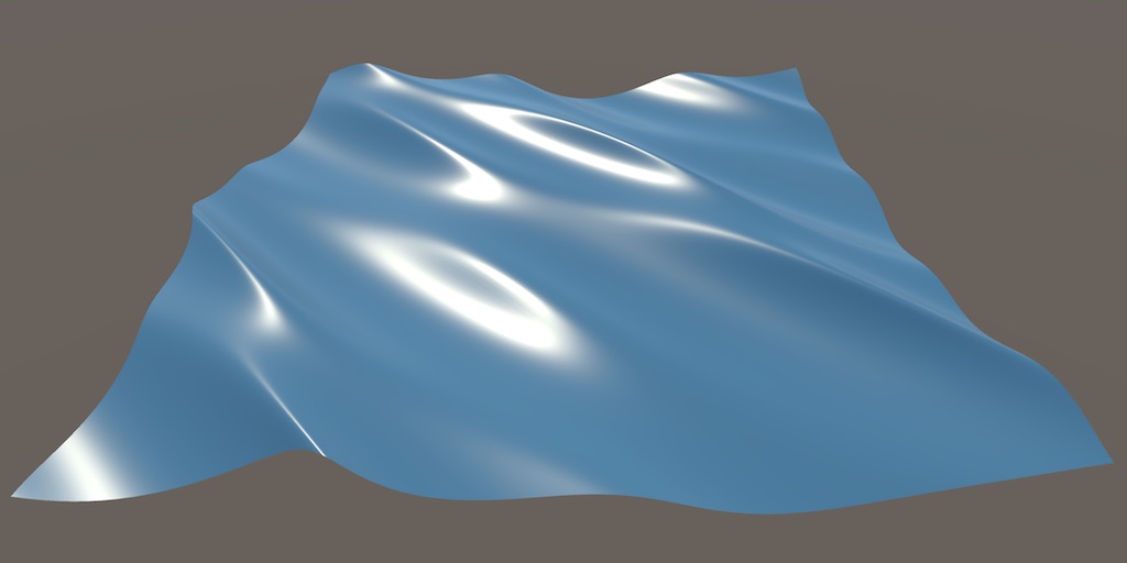
A Unity Flow tutorial about moving vertices to create waves.
can you reduce the wavelength on the waves so it's much smaller than the size of your plane?
it does make it different but it looks more like one gerstner wave compared to multiple overlapped
ive tried changing the values too in the editor you can see in the video on the right, as well as in the shader editor
For the overlapping one it seems they just added a copy on top but with the waves going in a different direction
I realised that when I add _MainTex it no longer works as i want it to, for some reason then replacing materials doesnt override animations anymore, is it alright not to have _MainText and just ignore this warning or is there proper way to handle this behaviour?

without maintex I get desired effect but I get this warning.
yeah athats what they did so i followed that and i cant seem to replicate what they have done
If you want to override animation I'd assume you'd want to swap the sprite out, not the material really.
But the warning might disappear if you have a texture with the _MainTex reference in the shader, even if it's unused & you sample a different texture property
ill try that approach tomorrow cheers
when I apply a shader graph to a 3d visual effect graph, is it making a 2d projection of the 3d object and then stretching the shader to fit that 2d projection?
My only experience with shaders is a 6 minute yt vid so i might be totally misunderstanding something
Could you make a screenshot on this and elaborate more on what you are doing?
I'd like to make a post processing shader for urp, I tried using the shadergraph stuff but I dont like it.
I'm trying to replicate what I did there in a regular shader but I cant even find a working template for one.
Does anyone know a simple one (for example like the color inversion example)
well the question i asked was more a conceptual question for my understanding of shaders. What I'm trying to do is to create a sort of wind vignette where the border of the screen has wind blowing inwards. I figure one possibility would be to use a wind shader in combination with unity vfx graph
No
Or it's probably not useful to think of it that way
You could think of it more like that a shader runs for every pixel that's occupied by the mesh on screen
(Though it also runs on vertices, and not technically on pixels but fragments, but)
So I did what u said and that was to still use mainText name and just swap out the texture. but that doesnt seem to work if the material has "maintex" name nothign seems to change default texture, unless i am writing wrong syntax here ?


This is code grab of replacing main tex texture 
You'd want to change SpriteRenderer.sprite as that it passed to the _MainTex reference automatically
not sure I understand what you mean because:

changing this doesnt affect it
Hmm, it's supposed to
I guess if you have a animator or something that might be overriding it?
ye changing out materials and not having reference set to mainTex is only way it works
but that does give that little warning
ye because the animator uses specific spritesheet
but whole reason I used shader is to avoid duplicating animations
I am fine with warning but I wondered if there was alternative way to handle it
I guess just use a different texture reference and ignore the warning then
As I mentioned before, adding an unused Texture2D property with the MainTex reference might also remove the warning
not sure what u mean by unused property
In the shadergraph blackboard, you can add multiple Texture2D properties
Have one with _MainTex but sample the other texture instead in the graph
inside the shadergraph i can see emissive lights


in the scene i cant
W H Y
its HDRP
problem: emissive is not showing in scene
iirc HDRP uses different units for emission so I think you need to multiply by some large value to increase the intensity, or put it through an Emission node
multiply + float ?
i ried both didn't work
ill try in new scene
Could that be a bug am using somewhat an old version
It looks like you're putting the shader on a mesh with only 2 tris as opposed to the tesselated mesh the tutorial seems to have, just a guess?
how could i check that, is that the wireframe?
Hello, would this be the correct channel to ask questions about the SRP?
Specifically I have questions regarding programming render features and passes myself
How could I add a shader on top of my existing material?
I want something similar to a Minecraft enchant!
Is it just make a shader that applies the texture normally, and optionally return something else?
you could use two materials and one has a shader. the shader material has the enchantment
how would i be able to update a shader from 2017, i copied a shader and need to update it to unity 2021
Yeah. But also if you are making a fishing boat game just use this https://www.youtube.com/watch?v=PtI9LYfx1Dc.

50% off The Dev Days of Summer sale on the Asset Store, for a limited time: https://prf.hn/l/dlR3glw
- Unity has a great water system in the boat attack project, and i'll show you how to import it to your URP project.
Boat Attack (Github) : https://github.com/Unity-Technologies/BoatAttack
Don't forget to like and subscribe for more videos lik...
unless you are set on spending your time getting that shader working, this tutorial should take you like 10 minutes and your game will be better for it
i might consider that thank you, but also the plane wasnt just two tris
if youre knowledge about this i imported that water plane and there is this odd issue that it follow the camera so i was wondering you might help?
Did you use the emission node to feed the final color and power and exposure weight?
That looks like a render distance issue, it's not actually following the camera
basically, the game engine is trying to save your resources by not unnecessarily rendering the water in edit mode when you don't need to. It should be fine in play mode, and/or if you zoom in close to edit stuff.
you can try unchecking dynamic clipping here though

and/or changing the clipping planes
ah, so each frame that is rendered, the shader is applied to whatever pixels the camera will see of that 3d object?
Basically yes, but there's a bunch of asterisks in that
If you want the full story I recommend
Shaderquest for a written format guide: https://halisavakis.com/shaderquest-part-1-graphics-concepts/
Or Freya for a video guide: https://youtu.be/kfM-yu0iQBk
Okay thanks, I'll take a look
Hey can anyone help me finding where I can use a smoothness map? I only see a 1 vector value and nothing else
chatgpt tells me i find the setting on the material inspector tab but there is none
I tried this setup

A smoothness map is just a texture, if you want to add one to your shader, just add a new texture property and sample that texture as the smoothness
It could be that the intensity value set in your material is 0 and the one for your shader isn't?
Also put the emission intensity into the emission node, otherwise I think the node is pointless (plus, color output is exp(HDR intensity)*color, not intensity*color; you can pick the intensity so it's the same but the former makes it easier to access a wide range of brightness effects)
You could show the material in question
Maybe it has the texture slot somewhere in there, or if not gives us some context of what you're doing
how can i set the output to HDR intensity
anyone here know any tutorial that teach how to make light mode for built-in shader?
Set your EmissiveIntensity in the material to some big value like 1000 or 10000, see if that changes the appearance in scene
the scene is no diffrent

the material preview changed

the preview in the asset folder
lol
it did work now

Thanksssss
i cranked it it borke the material and then made it smaller and worked
Thank you @karmic hatch thank you @grizzled bolt
@grizzled bolt you always come and save the day idk you are like magic xd

Not exactly a tutorial, but it will get you started.
ah... I'm using unlit one, do you have unlit one?
wait, I mean light mode like, foward, forwardadd, deferred, meta, showdowcaster
or is that the same?
For unlit, maybe this? https://www.youtube.com/watch?v=4XfXOEDzBx4
You want to make your own light mode? Like add one? Or you "just" want to know what those passes do?

Lets explore how to build diffuse lighting onto our meshes. This is intended as somewhat of an introduction to some of the magic behind shaders.
There are two types of shaders you will typically create a in Unity. The first is the Standard Surface Shader. These are very Unity specific ...
I want to disable a pass on on shader, if I click something on my custom shader GUI
and Material.SetShaderPassEnabled only work based on light mode
thanks I will watch that later
Hmmm... IDK if it works, but you could try to use shader variants and exclude the pass (or give it another name that won't match) to ignore it based on a keyword.
shader variant can exclude a pass?? do you have example how?
IDK, never tried it. Something to attempt....
from what I know you can't exclude a pass using #pragma shader_feature
Yeah, IDK if you can you have #ifs at that level. But otherwise it could be something like
  Pass YesFoo
#else
  Pass NoFoo
#endif```
But IDK if that will work.

I suppose the other option is to use conditional compilation within the pass and return a non-result/unaltered-result/discard in some cases.Is there a way with a fullscreen shader(s) to set the z buffer to filled only where the stencil buffer = 0, and clear the z buffer where the stencil buffer != 0?
Hey i have a pretty stupid beginner question: I get that the fragment decides for every pixel what the color should be. But how does it know which pixel i mean when the metallic input only uses one value?

Metallic can only be 0...1 float value as far as i know. How does it know that I only want the top right white part be 1?
The metallic port is only a single float, but it can be different per-pixel. Same goes for all of the ports in the Fragment stage there.
It varies here as the texture is sampled using UV coordinates stored in the mesh (UV0), which are interpolated across the triangles
Ohhh the UV0 refers to the UV of the mesh where I use the shader on?
You'd likely need to draw the fullscreen quad/triangle yourself rather than relying on cmd.Blit or similar functions as they don't set/use the depth target.
If by "z buffer to filled" you mean set to a specific value, you'd also need two passes as you can't read the stencil directly in the shader. Have one with Stencil Comp Equal, and another with NotEqual.
Have fragment output to SV_Depth to set the depth buffer value to 1 (or 0 in other pass). Should use #if UNITY_REVERSED_Z and 1-z to make sure it fills/clears on any platform.
If you mean left as it is, only need one pass with Comp NotEqual.
Thank you I think I get it now 
is "snoise" a built in hlsl function in unity
No, you need to write your own or find noise functions online for procedural noise in shaders.
There is some code on the Gradient Noise and Simple Noise node pages that you could use :
https://docs.unity3d.com/Packages/com.unity.shadergraph@12.0/manual/Gradient-Noise-Node.html
https://docs.unity3d.com/Packages/com.unity.shadergraph@12.0/manual/Simple-Noise-Node.html
ok. Im working on a new project with other people with an snoise function. I was just wondering whether i should be looking for it in unity or in the project itself
sorry to ping you like this but i saw you mentioned that you used catlikecoding's gerstner wave and recreated it. ive tried to follow that guide twice and recreate it as well as copying the shader and pasting into my unity project and having no luck as both times i recreated it it didnt function as the webpage showed even with the same inputs and when i copied the shader it was pink and didnt work. i was wondering if anything similar happened to you and if you had a solution to it, thank you
ty though
If you're in URP/HDRP you won't be able to copy the code from the tutorial as surface shaders are only supported in the Built-in pipeline. That's why it may show as pink/magenta.
oh does that mean even recreating from the tutorial as a shadergraph doesnt work?

A shadergraph will work yes. Well, assuming it's targetting the same pipeline in the Graph Settings.
can you expand on the graph settings part
As in, if you're in URP you need "Universal" listed under the Targets list in the Graph Settings tab of the Graph Inspector window. That window is toggled with the buttons in the top right of the graph
The magenta previews might also be something different though. Possibly dividing by zero or using negative values in a Power node for example
okay yeah i see that. i dont know if im messing up when making my shader but i made the shader twice from scratch and this happened both times so i dont think i made a mistake. so im not sure if there is a problem or my understanding not very good
Will just need to check the calculations against the tutorial to make sure it matches. Maybe the mesh has a different scale as what they use too so could try scaling down the input values.
ah crap thank you, is the meshes scale just the scale in the inspector
plus is there a way i can convert the copied shader to urp?
Might be the scale in that actual model. Kinda depends if the waves are in object or world space.
Not automatically. It's not impossible to rewrite with code, but easier to use Shader Graph, especially for lit shaders. You could try putting the Gerstner code in a Custom Function node though
https://docs.unity3d.com/Packages/com.unity.shadergraph@14.0/manual/Custom-Function-Node.html
Upon further consideration I think all I am after is where my quad is that sets the stencil buffer to a value I also want it to clear the z buffer so I can render something else there but i can't seem to do a ztest less and then write a new z value properly. My shader experience is lacking and I can't figure out what to search for to get my answers.
I put the gerstner code in a sub graph, is that the same thing?
object space, is that bad?
You'd need two passes. One with ZTest Less and the stencil write. Another with ZTest Always, Compare against stencil and using SV_Depth output.
Thanks. I just considered that myself once I looked up usage of ztest. I'll give this a try. I think the problem was my ztest was set for the sub shader and not the pass
Custom function nodes allow you to use HLSL code functions (though with a specific layout, see the docs link) rather than needing to convert code to nodes
Not really. I can't remember what the tutorial uses but I tend to apply the waves in world space then transform back to object (as that's the space the vertex stage output requires)
Either would work. Just depends if you want the waves to scale when you scale the plane or not.
I am having trouble understanding this combo. I somewhat know what scene depth does but idk how subtracting the A value ( idk what A represents here ) of the scene position leads to the effect seen in water shader and stuff.

Literally every tutorial just go like 'put this into this and you acheive the effect' and none told how it works.
I tried asking gpt but the response was as of 2017 there is no screen position node in shader graph
Iirc the a component of screen position is the depth of the transparent object your shader is on, so by subtracting the depth of the surface of the water from the depth of the bottom, you get how deep the water is
is there an (easy) way to get the UV of a frame of an animation? Trying to apply a UV dependant shader to an animation
ThePinkPanzer basically covered it above, but I'll also link my depth post in case it's useful, has a bunch of info on this kind of stuff - https://www.cyanilux.com/tutorials/depth/#depth-difference
It's not very clear what you're asking, is this a 2D/spritesheet type animation?
Hey can anyone point me to a good guide about shaders that gives me a strong fundamental knowledge of what I need? I'm fine with just using the shader graph but I would want to actually understand what is happening so I can write more complex shaders
Or should I stay at the unity documentation?
Anyone know a good shader for hair? I'm running into a issue using the standard shader for hair.

I have a dynamically created mesh which is simply an extruded triangle - it has 5 faces. 1 top, 3 sides, 1 bottom.
I assigned the top face one material, 3 sides another, and bottom another.
I would now like to add a shader that is visible on top of every face, kind of like an enchantment in Minecraft.
How could I do this?
My materials will change depending on circumstances. I want the shader to work on any mesh with any materials!
Huh it seems like just adding a material as a component should work for my purposes... (Dragging it from assets works so probably will from code also..!)
Hey can you manipulate the vertices position independently from the mesh's scale?
I scaled my mesh 100 units. But now when I move the vertices in the shader by 1 unit everything gets moved 100 units
just divide it back by the amount you scaled the object
If I am getting this right, I would recommend scaling the points instead of the object itself.
This would allow you to keep your scale normal!
Thank you this was a good idea
Could you explain what you mean by scaling the points?
Sorry I am not very familiar with Unity specifically so I am not 100% if this is available, but if there is a mesh edit mode (where you can move the points/lines/faces), then scaling the object by the points in this edit mode would keep the units consistent!
https://thebookofshaders.com/ is one. No need to restrict yourself to unity docs

The Book of Shaders
Gentle step-by-step guide through the abstract and complex universe of Fragment Shaders.
should I also include
Pass
{
    Tags
    { "LightMode" = "Meta" }
}
on gpu intancing shader?
is there vector3 for shader property?

No
I see... ok thx
difference between #ifdef and #if define()?
Wow this explanation is very good. But I still have some questions about Screen Position Node. Like what do the RGBA values of the split node represent when screen position node is connected to it?
Lets assume that the R G B values represent the screen position of each vertex and A represent the depth of the vertex from the camera. That means A is the depth value. Alright. Now Scene Depth node utilizes the depth texture which is basically a black grey white texture where each pixel represent the depth of the vertex behind it. So the way it works is, for each and every vertex of the object, We are subtracting the depth of the scene behind this vertex ( which could be rock under water or anything under our transparent material ) from the depth of this vertex ( A value of the screen position node ). Which will give us the distance between the background and our object. Is this the how it works? Or I got it all wrogn?
sign, floor, ceil are all intrinsic functions in hlsl
For reference, there is a list here - https://learn.microsoft.com/en-us/windows/win32/direct3dhlsl/dx-graphics-hlsl-intrinsic-functions
wow thanks 
Cyan what about this?
or maybe anyone?
They are equivalent if using a single keyword
With just #if, you can use && and || though so check multiple
Might find these pages useful for explaining # stuff more. https://learn.microsoft.com/en-us/windows/win32/direct3dhlsl/dx-graphics-hlsl-appendix-preprocessor
I see thanks!
Basically yes. Though as we are in the fragment stage it's not really dealing with vertices, but the fragments/pixels. But their positions are interpolated from the vertices.
what do the RGBA values of the split node represent
What the values represent depends on the mode on the Screen Position node. There is some explanations in the docs - https://docs.unity3d.com/Packages/com.unity.shadergraph@14.0/manual/Screen-Position-Node.html
In this case Raw mode gives access to the clip space position, which happens to include the depth as the W/A component based on how the projection matrix works.
You can get the same depth value a different way if you prefer, (also mentioned in my post) - using the Position node set to View space, Split, take Z/B axis and Negate.
I have two realtime lights on my url lit shader in opposite direction, I'm generating the UVs from worldspace, all the normal maps are in tangent space in my shader. what am I messing up here?

Is the normal map marked as a Normal Map in the import settings?
Oh if you're using worldspace UVs the tangent space conversion will be incorrect
If the texture is projected from only one axis should just need to Swizzle the normal map sample a bit iirc
ah I think I got it, I had a unpack normals node before my normal input
yeah, I feel it's not yet correct

If you set the Sample Texture 2D node to "Normal" mode it should do that automatically but either works
in one direction the light looks fine, in the other direction it looks inverted
Ahh perfect! Really appreciate the articles ❤️
If the texture projection is worldspace XZ projection, I'd use a Swizzle node on the normal output with "xzy". Change the normal output space in Graph Settings to World and connect that swizzled normal to the master stack.
If it's a triplanar mapping, this article might help - https://bgolus.medium.com/normal-mapping-for-a-triplanar-shader-10bf39dca05a
I am having an issue with my wireframe shader - in theory the ddx ddy are supposed to make it so each wireframe edge is a uniform width on the screen but for some reason certain edges are thicker than others and I havent been able to determine or solve why this is the case


is there a known reason why this is occuring? an unsolved problem?
this is where I got the code for the fixed width
studying it more carefully I see I made tons of mistakes in turning their code into nodes
working as expected after re-writing it all
u
How can I modify the tangent vector by using a normal map?

I'm a lil rusty. What was the way to isolate each uv tile? Or at least a group, like a column or a line

Ok, so I achieved reversed direction image panning like I wanted.

thats not really something you do, but just add them togheter if you so desire
Are subgraph property implemented as uniform?
#pragma exclude_renderers gles gles3 glcore, why did my shadergraph autogenerate this? and isnt this basically make opengls graphic api didnt render the shader?
iirc shadergraphs generate multiple SubShaders. The first one might exclude gles but the second shouldn't
hmm, i create shader but it didnt render in VR using opengsl and when MSAA is active, so i thought this was the problem
Material effectOverlayMaterial = Instantiate(GameAssets.effectsOverlay);
float randomHurtValue = Util.getRandomFloat();
effectOverlayMaterial.SetFloat("hurt", randomHurtValue);
Why does my SetFloat not get set in the shader? Am I doing it wrong? Here's how my URP Lit Shader Graph looks like!

(I made sure the shader is correct, and I can set it manually from the editor and it works!)
You need to use the "Reference" of the property, which isn't necessarily the same as it's name. It can be viewed in the Node Settings tab while the property is selected. It'll probably be _hurt instead.
Ohhh! Right, thank you! I forgot about that!
I'm trying to make each square have a different color for the whole panning duration. Any ideas?
Worked great, thanks again!! ❤️
You want UV coords that are continuous and not put through a Fraction node. You can then Floor (or ceil/round/truncate) and then Random Range
The issue is that, having these moving UV coords that I need for my texture to animate (see preview bottom right), I also want to apply different rotations, which are the different color values (black and white). So I need these colors to be in sync with the moving UV coords
Then do both. The fraction and floored uvs should still be in sync. One takes only the fractional/decimal part of the value, while the other takes the integer value.
I'm not understanding your suggestion
you are saying I feed in the fraction andthe pixelate effect node group the continuous UV?
This is what I got so far

You basically want to replicate the same calculations you're doing with the Fraction node, but with the Floor instead
So that you have both
A little messy, but something like this

Altho the preview is the exact same result
What preview?
As the divide node in your screenshot?

Might look similar but that one doesn't have the same offsets
Oh right, should be fine. The values are all above 1 so will display as fully yellow/red but they are different. When put through the Random Range you should get different coloured squares
Thanks! Got what I wanted. The previews threw me off 🙂
"Inline" shader question 🤔
Is there a way to do a local outline-within-the-bounds-of-the-mesh of a mesh without relying on a depth texture? I want to use it on a transparent material which doesn't write to depth.
It doesn't have to be outside the mesh like a real outline, but I am not finding many resources on google how to achieve 'inlines'
like what unity does when you select a mesh, except inside overlaping the polygons rather than relying on any kind of extrusion trickery

I assume surface normals will be involved in some way
maybe if I google normal-space outline perhaps
what
why don't you just use a camera with a rendertexture for those and use that as a "depth" texture to do your outlines?
bonus: the highlighted item can be the sole thing rendered there, making this super easy to do
rendering the entire screen just to outline a single mesh seems like a terrible and slow workflow
not very performant especially if I already have other cameras rendering other things
you're not rendering the entire screen...
k
so was your intent to get help or be a snark?
my intent was to get it done with the surface normals and not a render camera
render camera doesnt meet my use case
so you want a toon shader or an inverted hull, it's not helpful to say "like what unity does" in that case, because that's not how you get object outlines that ignore internal geometry
so what do you actually want?
I think my question as written was pretty clear
inline shader
opposite of an outline
Rendering overtop of the mesh itself an 'outline' that doesnt require any screenspace trickery
or cameras
Can't find the answer on google because inline just refers to functions and outline just refers to screenspace camera stuff which is 1000% not what I am trying to do
well, my concern is that you posted this
that image has an outline of a certain kind
but what you are asking for looks like this

note that internal geometry is being outlined as well here
so you are asking for different things with your words vs your examples
just trying to make sure you don't spend a ton of time on this just to end up with a look you don't want
Hi, I'm getting this error when trying to build, with a Unity shader that seemed fine in editor:
Shader error in 'Custom/Snow': 'mul': no matching 2 parameter intrinsic function
I provided the entire code, the mul with the issue is on hastebin line 140.
https://hastebin.com/share/aqoxocuyuj.csharp
Hastebin is a free web-based pastebin service for storing and sharing text and code snippets with anyone. Get started now.

The more important error is the second one, about invalid subscript "position". That's causing the mul function to break as a variable that doesn't exist hasn't got a type.
You're using v.position (under ShadowVertexProgram) while the appdata struct doesn't contain that, it's v.vertex instead.
I (attempted) to make a documentation for Shaderlab, not finished yet but I'm pretty proud of it
https://shaderlab-docs.whitetophat.repl.co/

tyvm, seems like that was it!
Is Keywords Enum made for code use or there's a way to use it in the ShaderGraph itself?
You can drag keywords nodes into the graph to have different values/calculations per enum entry. Is that what you mean?
Sort of what I'm inquiring. How can I use this to branch out in the ShaderGraph itself?
Seems like the enum value will influence which float it will pull from. I guess that's it. 🤦♂️
Hi
So, I have some small issues. I'm using a command buffer to schedule the call of diferent commands and dispatch diferent compute shaders
Some of those handle append buffers
The problem I'm having is scheduling the right amount of threads for the compute shaders that make use of the append buffers
My current solution is copy the counter value of the computebuffer into another compute buffer, get data and the counter, and use that, but I don't like that solution
Is there a better option to schedule append buffers, or should I dispatch according to the maximum length of the compute buffer always and make use of the counter value on the compute shader itself to skip the threads that pass the count amount
Aha! I can use a compute buffer with the arguments set there, perfecct
is there any shader graph basic tutorials from youtube or udemy or some site?
I just wanted to learn basics of shader graph
Im new to shader graph.
why I can't disable shadow caster pass, but I can disable Always lightmode pass?

ok nvm, this scam function only work on Always light mode pass only
the principle should be the same as the outline shader
but instead of extruding the outershell, you (eh... what is it called extrude inward?) intrude(?) the actual mesh
So I imported a gltf from blender into unity and it got it like 70% of the way there, but everything looks like it got covered in ashes (It's mirage from CSGO). Any Idea what might be doing that?

Howdy pardners! I'm just doing some fun little projects to learn, and one of them is making a 52 card deck of auto populating and numbering cards, but TextMeshPro is giving me grief. The TextMeshPro shader is set to Distance Field (which I understand to be the correct shader to make it behave like an object in the scene?) but it renders above the card back, which is a sprite renderer with a texture on it. I've tried setting the sorting layer, but this makes the text just vanish (I think it's being culled) when the card is viewed from a slight angle. The issue shows itself as all numbers showing through all cards, even when the cards are offset on the Z axis from each other...
How to I make the text behave in the scene like any other object?

Hi!
I am trying to see if I can get a portal-y effect within shadergraph only, without editing in a stencil tag so that I can use it with VFX graph.
Essentially what I want to know, is how can I set an alpha only when it's intersecting a plane or such... or maybe is within a cone eminating from a vector or something
@regal stag
Hello! Im struggling with my shader for a while now 😄
I want to have a hover effect on my gameobjects. i get this to work now, but my problem is, that the hover effect looks always different based on the color of the albedo of the GO.
That means, that the hover color have less effect on dark colored GOs and more effect on bright GOs.
Do you have a smart idea how to solve this?
I already tried to overwrite the GOs albedo with a flat color, but that doesnt look great.
Try adding instead of multiplying.
I already tried.. well then it adds a color on the brighter or darker albedo and has still different looks 😄
how do you do vertex animation on built in unlit shader?
I just want a simple animation now of grass moving left and right
There are nearly infinite tutorials out there
Happens whenever you just apply an semi-transparent color over the albedo color of the texture
You can also use a “mask” to not pass the albedo color and pass only the hover color
But without seeing your node setup, it’s not easy to help
How do I read SpriteRenderer.color in shadergraph?
It will be fed into vertex colour

is this normal? first time messing with the shader graph. it seems like this appears after i add the "Transform node"
I need to add diferent append compute buffers
Im currently dispatching this shader
StructuredBuffer<uint> _Origin;
AppendStructuredBuffer<uint> _Target;
StructuredBuffer<uint> Count;
[numthreads(128,1,1)]
void CopyIndices(uint3 id: SV_DISPATCHTHREADID){
    if(id.x < Count[0]){
        uint index = _Origin[id.x];
        _Target.Append(index);
    }
}
But this adds up

Any idea on how I could do this faster


Are you using a world space canvas?
?
Hello eveyone,
I'm actually trying to do a shader in URP but there is a problem with my preview in my scene. In my preview my fresnel effet is on the top of my cue but in my scene the effect is dependant of my camera and I d'ont know why :/ There is a screen of my shader and the view i got in my scene.


As you see the material is pink. then i changed it to lit from the urp shader. now its just gray, but the things like the base (rgb) normalmap and so on arent right and i want the textures on the material
Then you grab the texture and drag it into the right place in the material
But where do i drag it in? I mean the textures cant be dragged anywhere with the lit shader in use
.
I can put them on the base map but thats not how it should be
You can put the Base (RGB) Alpha (A) from your screenshot into the albedo of the urp shader
The other two are not compatible with the standard unity shader i think.
I dont know what Trans (RGB) could be.
you dont need a position node there
Where to find the albedo? 🙃
Albedo is a different term for base map, sry ^^
I dont think that is the tree xD

@fossil cloak I need it for later because I want to do a dissolve shader for the center to the edge on the top of my cube, that's why I put position node

Yeah, now try to set the surface type to transparent
you want it to be on every side of the cube?
How :>
ah seen it
@fossil cloak something like this

Nice but there are these little planes

i think thats the reflection. You can try turning smoothness to 0

Solved on my own!
Turning out Specular Lightning

Now you can change the smoothness and metallic without changing the planes
Fresnel is based on the view direction
If you just want a radial pattern like that, you can just take the (x,y) components in object space (using a swizzle or split -> combine or split -> Vector2 node) and then take the length of that
(alternatively I think you can plug (0,0,1) into the view direction slot and it should give the same result)
@karmic hatch Thanks a lot ! 🙂
np :)
Quick question!! Is there any way to turn off culling on the Standard Unity Shader?
.
I need to add diferent append compute buffers
Im currently dispatching this shader
StructuredBuffer<uint> _Origin;
AppendStructuredBuffer<uint> _Target;
StructuredBuffer<uint> Count;
[numthreads(128,1,1)]
void CopyIndices(uint3 id: SV_DISPATCHTHREADID){
    if(id.x < Count[0]){
        uint index = _Origin[id.x];
        _Target.Append(index);
    }
}
But this adds up
Any idea on how I could do this faster
I just need to add append buffers
Hello, i wrote a shadergraph shader, that uses dithering for some kind of transparency. If looks fine for me:
But for my collegue on his mac, its completly broken.
We already gave it to someone else, its fine for him too. Is there something weird with dither and macs?
Also the Material preview is damaged.. 😄
(first image is how it should look like)


@grizzled bolt - What is this emoji? 😄
Indicating that it is puzzling
Are you sure the problem is the dithering?
I think so, because when it’s deactivated it’s not shaking like that. The funny thing is, that also the mat preview looks like a bad hologram😂
https://docs.unity3d.com/Packages/com.unity.shadergraph@13.1/manual/Dither-Node.html the dither code isn't doing anything particularly unusual so it's a bit weird that it breaks
Perhaps you might be able to isolate the problem to some part of the function
https://github.com/RemyUnity/sg-node-library
I'd try different dither effects from here just on the off chance they avoid the problem
just got started messing with shader graphs, and I'm wondering what would be the best way to get an input texture and change its hue, saturation, brightness and contrast values before outputting it into the final product. using URP.
There are nodes for those
https://docs.unity3d.com/Packages/com.unity.shadergraph@13.1/manual/Artistic-Nodes.html
right, I saw all of those minus brightness, but how can I combine them back into the final image?
to be honest I'm not even sure if I'm doing the first part right

It may be helpful to assign a texture to the property ("Default" field in the Node Settings tab while property is selected). As well as play with the vector4 or swap out for Sliders temporarily to visualise what the nodes are doing.
You likely want to chain the Hue/Saturation/Contrast nodes together.
Though it might also be easier (and more performant) to swap it out for a Colorspace Conversion. Something like: Linear->HSV, Add or Subtract to offset values and convert back HSV->Linear.
by chaining them together do you mean getting the output from one into the input of the next?
alright, that seems to have worked. cheers.
one last question: I'm trying to apply the alpha values of my model's vertex paint to the final product. what kind of node would I need for something like that?
Vertex Color -> Split -> A would give you the alpha component of the vertex paint
seems to have done it. perfect!
Hello all; I'm looking to do a full-screen effect for a transition where I basically take a screenshot of the current screen, overlay that over top of everything while I change the scene in the back, then I would like to split the overlay image into cubes of uniform size, and have each cube "do something" like turn while and fade to transparent in turn, sort of like a cascade effect.
Sorry if this is a dumb question, but is a shader on the overlaid texture a good way to achieve this? If so, are there any simple examples I can look at that could get me started learning what I'd need to know to build such a thing? Not looking for complete hand holding but I'm not even familiar enough with shadery-stuff to know the right terms to use when searching 😄
You should not use Transparent. Ideally you should be using opaque and cutout, but if your material is not like glass it should use Fade.
Just google transitions in Unity. What you’re asking for here is fairly complicated to do in a shader and I wouldn’t advise it for a beginner. You’d be better off using a specially made mesh and a rendertexture and some simple code to set vertex colors over time.
Thank you; mostly what I needed was a guidance on "direction". I found a lot of scene transition stuff that was really basic, so doing an overlay isn't complicated and i'm not new to coding at all. If a shader isn't the right tool then I guess this isn't my excuse to start learning those 😄
I found this shader code I want to copy, can I easily convert this to unity? https://godotshaders.com/shader/speed-lines-shader-for-godot-4/ . I don't really know how this woks
I made this following a unity tutorial.
Haven't looked at it too in depth, but I think that it will be doable
Maybe with the new fullscreen shader graph if it's a full screen effect
I can convert this code to a shader graph?
Everything is possible. Might need some custom nodes, but it's probably possible.
No guarantees tho
any resources you reccomend where I could learn how to do this?
There also are tutorials etc on how to get these lines in Unity, maybe just a different way
yeah, I actually have speed lines like these already, the issue is I want the shader specifically, like the wind like gradient pattern
If you use particles or existing shaders you could change the color on those as well instead of rewriting everything.
But for shader graph look around google and youtube
ok, thanks!
oh um, is there an altenative to fullscreen shader graph if I'm using URP instead of HDRP?
Yes
2022.3 has it for both
Use the full screen effect on your URP renderer and put the material there
ok, thanks
anyone knows why my shader from shader graph is white in build? in editor it works and displays fine, in build it's all white


here is the shader

Okay thank you! I'll try that when I'm home
How do I add 2d shadow caster component to a tilemap and get it working? right now I think it just thinks the whole layer is one solid block, here are some screenshots:
first one is without it enabled, second one is with it enables


the tilemap has a tilemap collider 2d component so I'm thinking its something to do with that.
nevermind, I found out that theres no such thing for tilemaps
Hi Guys,
to achieve this kind of wave lines, which nodes should i use in Unity Shader Graph?

this is wave pattern with distortion in Blender node setup
you can use sine of (object space position dot [some vector], plus distortion) and then sample a gradient
There is no such node out of the box
Blender uses saw or sine wave math on object space position for the stripes, offset by a 3D noise for the distortion
Unity's default noises are all 2D
It is fairly easy to install 3D simplex noise (or use 2D noise at a different angle to the wavevector so they align and dealign in different ways)
thats true, i am achieving my objective with Gradient noise but i am not able to generate the strip thickness, let me share the progress here.
this is what i am able to do, but i want the strip thickness to be changeable with outer input factor.

this is how i achieved this, but is there any better way?

Hey guys, does anyone know why my decal is casting this dark, square projection when normal blend is > 0?


you can use it to sample a gradient, and then set the colors in the gradient to have hard boundaries rather than smooth ones
i have reached this far, but only 1 problem left now

with this setup

i am able to obtain this result

but how can i fix the stretching? is it possible to use triplanar kind of thing here?
Somehow, yes, but you will have to do the triplanar logic yourself (not that hard though).
And at the end, the blending will lead to lines discountinuities
Best would be to use a 3D noise, but shadergraph don't have any, and you will have to grab it from somewhere or do it yourself
actually i am new in unity node system, so i am not familiar with what particular node will be useful here,, 3D noise? but We can make our own 3d noise in Shader graph by using Sample noise and applying position node to it, wouldnt it work?
Shadergraph noise is a 2D noise, it takes 2D coordinates as input, and will result in a sort of "projected" 2D shape on a 3D object, where a 3D noise takes 3D coordinates as input and is coherent in all 3 dimentions
Here's a repo with some 3D noises for example : https://github.com/JimmyCushnie/Noisy-Nodes

GitHub
Adds various noise generation nodes to Unity Shader Graph, including 3D noise nodes. - GitHub - JimmyCushnie/Noisy-Nodes: Adds various noise generation nodes to Unity Shader Graph, including 3D noi...
According to the description, he took the code from Keijiro
its difficult for me to understand the workflow here, i will try for triplanar projection, will update any progress, if happens from here...
looks like i have to split the axis and rejoin them and blend the lines back.
The workflow would be : replace your noise node by a 3D noise node
ok, I will study the above workflow system then, thanks.
with perlin 3d noise, the stretching has been removed, thanks alot remy, one last question is, is this subgraph mobile optimized? i have no experience of coding and its code is 220+ lines.

Noise, in particular 3D noises are not mobile friendly in general.
To have better performances on mobiles you would want to bake the noise in a texture that could be applied to the car mesh.
I'm having a problem where shader graph is all buggy and can't connect nodes that should be able to connect

Avoid having node chains connected to both the Vertex and Fragment stages
So you are saying I will have to have 2 groups that are exactly the same, doing duplicated operations?
Depends what you're doing. Could use a Custom Interpolator to pass a value from the vertex to fragment stage. Otherwise the calculation will still be duplicated in the generated shader code anyway
Do you have any blogpost on that or that has any implementation on your website?
This explains it a bit & has a couple examples : https://www.cyanilux.com/tutorials/intro-to-shader-graph/#custom-interpolators
Though in this case if you are altering the vertex position. When using the Position node in the fragment stage it'll already be the displaced/rotated position so that might be all you need?
I see what you are saying, however, there's some calculations after that seem redundant to have twice in the Graph.
Like so

whenever i try to put a material (with a custom shader) to a plane (or any other object), it does alot of errors like these, when it goes up to 285 it delays every time it makes a error


The fresnel effect is based on the mesh normals.
Look at how it appears on the edges of the preview sphere as the faces are more and more at a grazin angle.
Since you windshied style mesh doesn't have this type of smooth rounded edges, the fresned is not visible.
In short : fresnel is not an outline
Ahh that justifies the fresnel tint to show when I look on the plane at an angle.
What can be the approach to solve the issue though. Like am I supposed to create a outline texture then multiply with some color and put it into the emission?
Yes, this is a solution
It kinda works now but there is another problem I am facing.
I have two parts of the shader, first part creates the outline using a texture I created.
Second part add intersections using scene depth node.
To show both of them at the same time, the output of both parts should be added and then plugged into the alpha.
But the individual parts work and when I add both of them, the final result doesn't.


saturate the top one i think
if it goes negative then it'll break everything
might be natural to take the maximum value too
yeah here you can see it's subtracting from the texture value until it reaches zero at which point it just becomes transparent

(probably best is to take the max value though, that way when the texture and edge detection parts are both lighting up it doesn't make it double-bright)
So this means, as of now the output of OneMinus node may have negative values which when supplied directly into the alpha give acceptable results as any value less than 0 is basically 0. But when these negative values are added to the output of the texture node then they cause some of the positive values to drop down to zero and hence removing the effect of texture at some places?
yes exactly
in general if you think your value might go outside the required range, it's good to saturate it and that way it doesn't do anything unwanted
Makes sense. I clamped the output of OneMinus Node and it works perfectly as intended now.

Thanks
https://docs.unity3d.com/Packages/com.unity.render-pipelines.universal@15.0/manual/containers/post-processing-custom-effect-low-code.html
^ this is for shader graph only, not sure if that's what you want
oh sorry I found something online already, thanks for the help though!
So how would I go about taking a model with a bunch of separate parts with separate textures on it, and baking them all into a single texture for the entire model?
Shader Graph Transparency Issue
I made this shader with the stencil buffer that can render objects like a portal, it works fine as i want, except the portal gets drawn over everything. Even at the back of the portal you can kinda see with the colors I provided. Also shared the settings I'm using in the URP render features I made but I tried and this is the best for me, only thing is that rendering on top. I know transparent objects have something with the depth buffer that is messed up, is there a way around this so that that green thing and the red ball will be drawn on top instead of behind?
Thanks in advance!
(Also I made two render features that load the objects normally and I switch between the correct ones with code and triggers inside the portal gameobject so don't worry about that)
EDIT: I fixed it already. I just changed the Render Overworld Objects Normal from a stencil overwrite to a depth overwrite, set to less.

Hello!
I have made this "Fog" Shader Graph, and for some reason it's obstructing light coming off other sprites in my scene.
As you can see, the "stars" each have a light attached to them, but when I use the Shader Material, it's obstructing them.

These are my Material and Shader Graphs:


I am new to these so I apologize if it's an obvious issue
I tried to set the Shader to "Lit" and "Unlit", no change was visible. I am also certain the sorting order of the stars is higher than that of the fog
Any idea what it could be?
Thanks in advance:) < 3
Is it a Sprite Graph?
Are the lights 2D lights?
Yes
Good question. I'm not sure what you mean so I'm guessing that could have to do with it
https://docs.unity3d.com/Packages/com.unity.render-pipelines.universal@15.0/manual/ShaderGraph.html
It may help to make it an unlit sprite graph since you're using it as a sprite
Otherwise it might not work with sprite sorting at all
Yeaah
I believe sprite sorting is working fine
I tested it
Only the light is getting obstructed
But I'll try to use a,Sprite Graph and see if it fixes it
Thanks!:D
I need some help with a build issue. I have a simple shader graph that contains a custom function that simply takes a colour (and world position) & finds the shadow attenuation for it. This works great in the Editor, but when I build the player it doesn't show the shadows (DX11 & DX12). I presume this is to do with the boolean keywords for main light shadows being stripped? But I have no idea how to confirm this or fix it.
Does anyone know how to get the point/spot light position in shader graph (via custom hlsl)
Hello everyone, i'm trying to do a URP shader to change the skin of a cube but in a particular way.
Actually, i'm using Position > Polar coordinates > Split (R) > Step, to get a circle on the top of my cube that can shrink or grow but i'm actually stuck for the rest cause of the growing is not like I want. It's probably something about UV but I don't what I need to do 😅
Do someone have an idea to help me ? Thanks ! 🙂


You'd likely need to handle the top/sides separately, and choose which to display (Lerp, or Comparison & Branch nodes) based on a mask - in this case the Y axis of Normal Vector
For the sides I'd probably Step the Y coordinate of the Position
Could use vertical axis of UVs instead but depends how it's unwrapped then
So I need to use 2 shader, one for the top and one for the edges ?
Or use particular UVs on my cube with what i have actually ?
Would still be one shader
Whether you need specific UVs depends if you base calculations off the UV node or Position. In the above you're already using the Position, might be fine to stick with that.
@regal stag ok I tried the comparison node and it's look very usefull in my case, I understand more what you explain to me . Actually i'm trying to get the circle that can grow only on the top of my cube
@regal stag I actually do this, so the shader is only on the top of my cube, the top face is black if < 0, white between 0 and 1, and white on the side if > 0. how can i get back the circle pattern in this case ? Do i need to use a texture or something like that ?

response to this: you have to get the normal vector on the object space, split it and use one of the coordinates
@regal ivy the fact is i don't know how to manage a normal vector + my polar cordinates nodes to get a circle on the face 🥲
So I got the effect you wanted. It took a lil bit because I come from Blender Node-based shading and the workflow is slightly different

So, the key here is that Normal Vector of the Object shows us the face direction values, independant of the object's rotation, because it is in object space.
So, in this case, using Normal Vector (Object) I split into XYZW(RGBA) and isolated the Y(G). The face up is the only face that has a Y(G) value of 1. So, using the comparison, I compared the normal vectors' Y(G) values that are greater (redundant) or equals to 1.
I notice there's a weird behaviour when rotating the cube, where the circle disappears. Replace the comparison value from 1 to a number >= 0.5 and < 1. I don't know why this happens tho
I was doing this and i'm gonna ask you if it was the good way to get the effect x)
Thanks a lot for this and for your explanations
i'm going to try to do the second part of the shader now, thanks a lot 🙂

@regal ivy I do this for the second part ( sliding from to to bottom on the edges, and it's works, now I have to connect them. Does it's looks good ?

Rather than Rotate, I'd use a Split or Swizzle and take the Y/G axis
@regal stag Done 🙂
@regal stag Here is what i've done, I restored the rotate because i can't get the white from top to down with a value from 0 to 1. I don't know if it's the good way to mix the effects but it works ^^' Now I gonna try to put some color on this

This graph ^ doesn't make any sense to me
well, mostly the part where position is piped to a uv input and rotated
looks like a convoluted and somewhat unsupported way to get the y-coord out for comparison?
I would just use (object pos. + split node) to get y and then remap (using the object min/max y) to get 0 to 1
Is here ayone with a advanced monke brain that can tell me how to make a procedural cristal shader for 2D work? Im kinda new to shaders and dont fully get the concept...
Hi everyones, i would like to know if its possible to take the main hdrp lit shader and make a variation with a rotation in the triplanar options. Is it possible?
Everything is possible 🙂
Yeah i know everythings is possible and sky and beyond is the limit ahah, but is it possible to start from the existent shader of hdrp lit, or I need to recreate the shadergraph? Im still new to the shadergraph.
You can take Lit shader (actually you need many shader include files from hdrp and core packages), make local copy of it, and modify as you like. But HDRP Lit shader is a complex thing, so it is not always obvious what and how things need to be changed. If you’re not so good at writing shader code, maybe better to go shadergraph way.
Thanks, it's just that i would have like to keep the HDRP lit material and all its features and just add the option to rotate my textures in triplanar. Would have been nice.
This shouldn’t be hard
hey guys

i got a colour map texture
and the base map texture
and basically, id like to apply the colour maps colours
onto the base map texture
how can i do this
Multiply sample values from this textures?
sure i can try but
how do i first colour the colour map texture?
like for example, how do i change the green... to some other colour
If I correctly understand your task is to “customize” colors of objects with base map. For example to make similar objects not so similar by altering its colors?
i have a base map, and a colour map, im assuming how ti works is, i change the colours on the colour map
and then apply the colour map to the base map to change the colour of hte object
so like imagine a character, wearing some clothing
id like to change the colour of his clothes
with the colour map
I'd probably put the colour map R output into the T of a Lerp node. Set A to white and B to primary colour.
Put result into the A port on another Lerp with colour map G in T port and secondary colour in B port.
Then Multiply with base map.
alr thanks i will try this
u know what sir, i think you are a god damn genius!

that worked lol
how you think of this stuff in ur head is quite amazing
A question regarding shader speed:
I'm applying a gradient to the top and bottom of an image.
I was doing this with an if-else to check the y value in the frag() block
    // bottom gradient
    c = lerp(float4(0, 0, 0, c.a), c, (IN.vertexWorld.y - _GradBottomYMin) / (_GradBottomYMax - _GradBottomYMin));
}
else if (IN.vertexWorld.y > _GradTopYMin) {
    // top gradient
    c = lerp(float4(0, 0, 0, c.a), c, (_GradTopYMax - IN.vertexWorld.y) / (_GradTopYMax - _GradTopYMin));
}```
I replaced this with some step() shenanigans instead
```fixed top = step(_GradTopYMin, IN.vertexWorld.y);
fixed bottom = step(IN.vertexWorld.y, _GradBottomYMax);
fixed middle = step(IN.vertexWorld.y, _GradTopYMin) * step(_GradBottomYMax, IN.vertexWorld.y);

// carbuncle of steps
fixed4 col =
    (top * lerp(float4(0, 0, 0, c.a), c, (_GradTopYMax - IN.vertexWorld.y) / (_GradTopYMax - _GradTopYMin)))
    +
    (bottom * lerp(float4(0, 0, 0, c.a), c, (IN.vertexWorld.y - _GradBottomYMin) / (_GradBottomYMax - _GradBottomYMin)))
    +
    (middle * c);```
I'm not sure which is better.
Is branching bad enough to justify using step() and just executing everything in those branches?Is it possible to create custom passes in the builtin pipeline?
Maybe with replacement shaders? https://docs.unity3d.com/Manual/SL-ShaderReplacement.html
Afaik branching isn't really that bad, especially if nearby pixels take the same branch which they'd probably do here. But you could add [Flatten] before the if statement to hint to the compiler not to branch if that's what you want to avoid. (Though I think that only works on some platforms)
Turning everything to steps works, but is probably messier. There's also ternaries (bool ? a : b) which always flattens too but probably not that much different.
If you really want to know which performs better you'll likely need to try them and profile (with something like Renderdoc)
#Cyan thank you for taking my question
Shader compiler can make your branched code linear with both branches executed (just like in your second snippet). To check this you need to look into assembly generated from your shader. But, if true branched code was generated then first snippet will be faster because your shader is ideally coherent: if branch executed for bottom part of the image and else branch for top part.
Hey everyone. How can I open code of a shader made with shadergraph and save changes in it? As I see "view generated shader" doesn't allow to save changes
The generated code is in temporary files which are deleted sometime later. If you want to make edits you need to "Save As" somewhere in your assets folder and swap which shader the materials use. But then it's shader code not a graph anymore.
thank you
Good to know. 👍
We have potentially a lot of platforms to target so I think I will keep one of these versions in the comments in case we have to revisit it.
in the unity documentation theres a page with lots of shader examples for the builtin pipeline. I cant find such a handy list of examples for URP
How can I acheive the desired effect in shadergraph? I want the alpha to ignore the semi-transparent areas. I was able to acheive this in a custom shader, but the sprite lit shader in shadergraph does not have an alpha thershold option, and I cant find any resources to help me with my issue. How can I just add alpha thershold to sprite lit in Shader Graph?

im currently learning about shaders and i go with the code approach since im already a professional programmer. It involves...soooo....much math. I didn't have this kind of math in school that i need except for basic stuff. Does anyone has good resources online where I learn 99% of the stuff that i need math related. Vector Mathematik, Trigonometry and Linear Algebra...smth else?

I heard Khan Academy is the way to go
Or maybe a more pratical approach would be to learn as you go?
Im very close to discovering my own solution. Ive created this custom node in shader graph, but why is it coming out as blurry/soft edges? Any idea?

SRPs is more complex than built-in renderer. And what is more important that there are no surface shaders. So shader graph was born.
Afaik if you output an alpha of 0 there shouldn't be any semi-transparent areas then
The SamplerState is probably set to Linear rather than Point sampling
Ah the legendary Cyan. Thank you. Now i can go back to my project ❤️ You were right ;D I had to set it to point

anyone have an answer for this? ------> https://forum.unity.com/threads/urp-lit-shader-in-shader-graph.962481/
Unity Forum
Is there a way of starting with the URP LIT shader and extending it with Shader Graph? Or do I need to rebuild the entire LIT shader graph and add my...
im using normal from height in URP shader graph and the normals are being lit by a light that is being occluded by the mesh
Shader "Custom/InvertColours"
{
        SubShader
    {
        Tags { "RenderPipeline" = "UniversalPipeline"}
        LOD 100
        ZWrite Off Cull Off
        Pass
        {
            Name "ColorBlitPass"

            HLSLPROGRAM
            #include "Packages/com.unity.render-pipelines.universal/ShaderLibrary/Core.hlsl"
            #include "Packages/com.unity.render-pipelines.core/Runtime/Utilities/Blit.hlsl"

            #pragma vertex Vert
            #pragma fragment frag

            TEXTURE2D_X(_CameraOpaqueTexture);
            SAMPLER(sampler_CameraOpaqueTexture);

            half4 frag (Varyings input) : SV_Target
            {
                UNITY_SETUP_STEREO_EYE_INDEX_POST_VERTEX(input);
                half4 color = SAMPLE_TEXTURE2D_X(_CameraOpaqueTexture, sampler_CameraOpaqueTexture, input.texcoord);
                return color;
            }
            ENDHLSL
        }
    }
}``` Why does this shader result in full grey in URP? The render pass seems to work fine if I leave the color as is. CommandBuffer cmd = CommandBufferPool.Get();
Blitter.BlitCameraTexture(cmd, m_CameraColorTarget, m_CameraColorTarget, material, 0);
// Execute the command buffer
context.ExecuteCommandBuffer(cmd);
cmd.Clear();
CommandBufferPool.Release(cmd);```I'm using this to call the Blit, and I'm doing the stage at the BeforePostProcessing RenderPass event
(Also if anyone knows any good docs for this stuff please let me know the unity docs suck for this)
As it uses _CameraOpaqueTexture, the Opaque Texture option on the URP asset needs to be enabled.
Personally I don't like using this texture (afaik it'll only contain opaque geometry so is kinda useless in events other than the After Rendering Skybox?). I always just make my own intermediate textures.
I also wrote an article which you may find useful - https://www.cyanilux.com/tutorials/custom-renderer-features/
I have a water shader. I want the screen to get bluer when the player submerges under the water. What is the best way to go about it? Should I just place some postprocessing volume under the water plane that turns the screen blue? Or are there more efficient ways?
Depends on what else is going on in your game and how it is set up
perhaps you have a light and you can just change its hue
Hello ! I'm looking to modify the basic HDRP Lit shader (Unity 2023) in HLSL in order to modify the saturation of every materials that I used with this shader.
I'm very new to this so I used ChatGPT at first but it doesn't seems to work and looks like sometimes, it's erasing the code I'm writing when I'm saving. Any helps on that please ?
Here is what ChatGPT Suggested to me.
Here is what I've done in the shader.
Here is the result (nothing changed) in the properties.
Thanks in advance for your help !


Thanks, I'll give this a look. What should I be using instead? _BlitTexture similarly gave me nothing
hey anyone know how to make black part move faster?
Do you want to "split" the screen if they're 1/2 way under water...so only the bottom is blue? OR
Do you want the entire screen to simply have a blue tinge to it?
If the latter, you can apply a post processing effect as you mention...or the alternative is for ALL the shaders/materials for ALL the objects to add a blue tint, maybe from a shader global. That way you only draw things once, and that's your answer to efficiency. You could also possibly add a Y-height conditional to compute the "above/below" value of your water plane, but without more calcs you won't deal with the waves properly. Similar to "unity fog".
But you may find that a post-processing effect's impact is negligible.
like it has acceleration
Also, read your tutorial, it goes very in depth. My only two notes: It could do with a minimum working example, it would be nice to walkthrough a very simple render pass without all the profiling etc just to get people started.
Also, is this true for the Blitter API as well?
When rendering we need to make sure we do not read and write to the same texture/target as this can cause “unintended behaviour” I see this being done A LOT in unity examples.
Afaik yes
There's a "full example" section (code in foldout), somewhat already pretty minimal. https://www.cyanilux.com/tutorials/custom-renderer-features/#full-example
(Sure you could remove the profiling scope but it's better to have that so you can actually see what's going on in the frame debugger)
Have you got any HLSL examples? I find that's what's most inconsistent from what I've seen, especially for camera effects.
With the camera colour thing, is it because the _BlitTexture uses texels etc that I can't read from it?
How should I be reading the camera colour?
I've used this with the Blitter API - https://github.com/Cyanilux/URP_BlitRenderFeature/blob/2022.1/BlitExample.shader
Afaik should be using _BlitTexture to obtain the source of the blit.
If you just want to apply affects to the screen there's also the Fullscreen Pass Renderer Feature that URP provides in 2022.2+. It's designed with the Fullscreen graph in mind but that kind of shader should still work with it
Using that shader directly:

Yeah I'm looking to do some raymarching stuff, so a bit too complex for that I think
            half4 frag (Varyings input) : SV_Target {
                UNITY_SETUP_STEREO_EYE_INDEX_POST_VERTEX(input);
                float4 color = SAMPLE_TEXTURE2D_X(_BlitTexture, sampler_PointClamp, input.texcoord);
                return float4(1,0,0,1);
}```Changing it to that

Yields this, so the shader is running properly
(Original scene, for ref)

how expensive is modifying a float in a shader material via script? Should I bother only doing it when it changes, or is it so trivial that its fine to do every frame?
Not a big deal
ok thanks
As with all things performance perspective is the key. Doing it on one material not a big deal, doing it in hundreds or thousands of materials it could very well turn into a problem. As a rule of thumb, do your naive implementation first and profile if it hurts your frame budget
the game im working on is not the type to be super performance intensive, so my biggest priority is gonna be bigger performance bottlenecks.
Does anyone have any insight on accessing the colour or depth texture inside a Blitter.BlitCamera... Shader?
why cant i change the output nodes of a subgraph
its a vector4 but i need it to be a float
nvm
why, despite the lerp displaying a blue image the main preview is pink

hdrp
its not exactly a complex shader

Make sure the target assigned under the Graph Settings (tab of Graph Inspector window) matches the render pipeline you're using
ok
no longer pink but my shader is a little off
its supposed to be having a a constant depth visibility
but moving camera position does not work with that
turning the camera acts as normal but moving up and down distorts the texture in a way i did not expect
Seriously, no one?
            SAMPLER(sampler_BlitTexture);


            half4 frag (Varyings IN) : SV_Target {
                UNITY_SETUP_STEREO_EYE_INDEX_POST_VERTEX(input);
                float depth = SampleSceneDepth(IN.texcoord);
                float4 color = SAMPLE_TEXTURE2D_X(_BlitTexture, sampler_BlitTexture, IN.texcoord);
                return 1 - color;
}```An intermediary rthandle seems to help fix the invert shader in game view, but the scene viewer is still really strangely affected:

Might have negative values in the result which is acting weirdly with tonemapping. I'd try a saturate()
Out of curiosity, why would this only happen in scene view?

Game view looks like this
That I'm not sure about
Is HDR disabled on the URP asset maybe? That might cause game view to use LDR textures (already clamped between 0-1). While scene view might always be HDR
HDR is enabled
Let me try remove saturate and disable
HDR Off: Scene view is fine
HDR ON: Scene view is broken unless saturate is used.
Some google searches doesn't seem to reveal much about why scene view would be like this, other than some other people complaining about bugs with HDR appearing only in scene or game view and not the other.
Hm well, not sure why game view isn't affected as well without the saturate. Probably makes sense to keep using saturate to remove negative values here.
Maybe game view just clamps those values itself, but honestly who knows.
@regal stag can you read a texture at a supplied UV (not a UV on a vertex or fragment) in shader graph?
Can attach a Vector2 to the UV port on the texture sample node
@regal stag excellent. thank you
@regal stag if i sample a texture at a bunch of locations (10 or so) how do i get the smallest value sampled ?
@regal stag is there a way to pass an array of floats to shader graph?
If you use a custom function yes, https://www.cyanilux.com/faq/#sg-arrays
In URP/HDRP it can only really be set globally due to SRP batcher stuff
Minimum nodes or min() functions
cool. thanks
Please also ask your questions to the whole channel and not @ me directly
ok sorry
Is there any way to quickly decompile shader graph nodes to look at what it's doing under the hood?
An example of the generated code is included in the documentation of most nodes. You can also see the generated shader code of your shader and look for the node functions.
Can't say I've seen that in the docs much, if at all.
But thanks, that's a good tip
Also, quick question should I be using HLSLPROGRAM or CGPROGRAM
Good practice seems to be hlsl according to wiki, but most examples I see are CG
For URP/HDRP, you should be using HLSLPROGRAM. Either way, it's all HLSL, but if you use CGPROGRAM, Unity will automatically include some functions and types that are found in CG, which you don't need for URP/HDRP.
Input nodes are more than just a single function, so it's not as simple to show the generated code.
Thanks, that matches up with what I observed on wiki etc, hard to know what's current good practice
We can define our own output struct for the Vert shader right?
We don't need to use Varyings specifically?
I don't think URP or HDRP has any built-in Varyings that you can use, it's always redefined per shader. So you can use any name, but might as well use Varyings to match all the other shaders.
I think Blit.hlsl defines it
I haven't defined it myself
How can I see the generated shader code of shader graphs?
Select the graph asset in the project and the button to show the generated code will be in the Inspector.
Oh wow thanks I missed that completely
Though the compiled code just seems mostly assembly, impossible to read
Compiled code is not the same as generated code.
I think I'm lacking sleep, I didn't realise you could scroll up to see that
Apologies, and thanks
Is there any way to make my view direction work well in scene view? It's currently basically completely broken

Scene view
Game view

Colours clipping and wrapping again? I guess.
Saturate fixed it in any case
I have a material in shader graph and I want to make it render in multi-pass or it wont render in VR otherwise. Is there a way of changing the render mode of an individual object without affecting the entire project in project settings (to benifit from single-pass instanced performance)
Is there an easy way for shadows to be pixelated rather than having smooth edges?
I'm trying to add the option to replace a solid color with another in a standard shader code. However, all features eventually stop. Can anyone who knows shader help?
So how would I go about baking multiple textures into one? Like I have an object that uses a bunch of different textures, but I want to merge them all into one single texture so that when I export it, I only need to apply a single texture image to it
Usually you do this in a modeling program separately from Unity
would I be able to do it in blender?
Yes
could you point me in the right direction to go about doing that?
I am having a problem getting direction in a shader.
I am trying to get the direction between the camera and the object, direction = destination - origin (right?)
But in my scene, every single mesh moves the same direction, even though every object should have different world space positions

is object position node not in world space? or am I doing something wrong elsewhere? Where is my mistake?
expected output is different direction vectors depending on thje direction btween the object and the camera

but the output im getting is the same direction for every single object, even though the camera position is clearly smack dab in the center of them
all of this is xy

what I really want to do is get the Orthographic camera's XYZ position, the object's XYZ position, and use that to move the vertexes in shader to give paralax based on the difference between the mesh's Z position in world space, and world 0
in a direction relative from the mesh to the camera, to get paralax depth
NOT from the vertexes individually but from the object as a whole
im adding the direction from cam to object to the verts but all objects move the same direction and that makes no sense

also they flip the fuck out based on my editor camera? Which makes no sense because editor camera is not sampled anywhere in the shader at any point
nor is view angle or literally any variable at all other than the vec3 being passed in

why would any of this cause random positional flickering
I dont understand and I cant debug it
Why do my textures look like this when i sample them

"like this"?
this is what the original looks like

I expect because there's no texture alpha plugged to Fragment Alpha input
Hi Guys, is it possible to design this kind of lines distorted in Unity Shade Graph complete procedurally or i should use some external textures as well?

you can do it fully procedurally but usually it's more performant using lookup textures
an idea would be to draw lines along the UV of the mesh and distort the UV with a noise texture applied
a seamless noise texture is required or if you want the full procedural route you can use the gradient noise node or the other noises
I have 3d Perlin Noise Shader Graph, Should i just import a wave pattern texture and distort it?
by wave pattern you mean straight lines?
it's just a word that describes a texture that has some kind of data that would otherwise be calculated runtime
so in this case the data is the noise
oh ok.
noise, especially 3d perlin is expensive
3d perlin is expensive for mobile games?
that works
I'm certain it is
it was a code of subgraph written by some developer, i didnt knew, this would be issue, because i already used it for a texture, let me share that here, but it hasnt been tested yet in the mobile device
testing it would be wise, but I have a feeling it's not a good idea
I mean the usage of it
got it.
im struggling with the scene depth node. It seems to return a binary value. everything is either black or white.
this is 3d Perlin noise Based Texture.

Ive tried linear and eye and raw and ive tried a bunch of remappings. I only get binary values. It says all pixels are equally far away.
what are you trying to achieve?
I wanna read values from my inspector
What kind of values? What's the whole picture?
You wanna split the scene into parts and you wanna debug that?
You gave me 3 seemingly unrelated things and I'm not sure what you want to tie together and how
because there's no simple way of just reading an output of a shader
Uhm, So... I send a texture2d where each cell can store uint, when the gpu is done calculating and assigning a value for each cell/pixel, I want send to the cpu the texture, and I want read every value o each cell/pixel
@cosmic prairie are you still there?
Does anyone know how to read and map a gradient in HLSL? Trying to make a toon shader with the shading controlled by gradient. How can I plug a gradient and read from it in a custom HLSL function in shadergraph?
Hello, how can i make the shader graph material to fit the sprites shape ? Right now it looks like this

What do you mean? It looks fine, what part is wrong? If you're talking about the outline, is it actually causing you issues? Because that's just the mesh
when the character moves the head of the sprite is flickering also why does it look like this in sprite default material? The orange outline fits the sprite perfectly

Are you using a sprite shadergraph?
i think i created lit shader graph. Do you think that's the problem? I'm gonna create it again
it should be using the one designed for sprites, there is a lit version of that
all right txh. i'm gonna try it now
i created a sprite lit shader graph, same thing happens
and animations also doesn't work when i apply the shader graph material
i can see the changing animation sprites in the sprite rendere but i can't see them in the scene
Are you animations doing sprite swapping via the sprite renderer? If so you're probably not using the correct name for your texture
yes. the texture i dragged to the sg material? How should i name it?
It should be set as an exposed property and called MainTex