#archived-shaders
1 messages · Page 51 of 1
Not sure about intellisense, but there's some neat references of the built-in includes here : https://xibanya.github.io/UnityShaderViewer/
And a URP version : https://xibanya.github.io/URPShaderViewer/ though I personally look at that ShaderLibary via the packages on Github. https://github.com/Unity-Technologies/Graphics
Hello again ^^' can someone explain me the "deformation part" in this tutorial ?
actually i have this but i don't how to deform my noise with the texture of the deformation part of the video
if i try to add my noise with deformation texture, i don't after how to connect it with the rest of the shader


Could you send me the horizontal thing?
- Will shader be discarded if it reads data from a not initialized structured buffer? Something like null ref error in c# when referencing an empty array
- Context: my shader works properly in editor, but doesn't render at all unless buffer is updated in build
It depends on what you mean by initialized. You will get an error if the buffer wasn't bound, allocated correctly or whatever.
If it was bound and allocated correctly, but you didn't copy any actual data over, then you will typically get default values from reading from it
- Well, i don't get any errors. After i change my shader to return fixed color value without relying on the buffer, it works properly in build. I will try to force 1 as the alpha value tomorrow and see if my shader outputs black colours. But why do behaviours differ in editor and build?
Is the stencil feature in the fullscreen shader graph bugged? When I set the reference to non-zero and the comparison to equal, the shader still executes
what are you trying to do?
Just spend the last 3 days figuring out how to add biomes to my infinite terrain (no tutorials apart from the intitial terrain by Sebastian Lague) using default cg shaders. It was difficult but my solution was pretty satisfying.

Hello
The standard way to make hair for 3d game characters is to populate the head with lots of transparent hair cards, but wouldnt this massively slow down performance since there is a lot of transparent objects stacked onto each other?
If you are using VSCode, you can use the Shader languages support for VS Code extension
might be easier if done using normal map
they wouldn't be transparent if you simply alpha clip them
Hi, just wondering if anyone more experienced with shaders could give this a look over and tell me if there are any obvious pitfalls here? (Other than it being a geometry shader of course - I did attempt to implement the same by compute shader but found all sorts of issues and limitations, such as having no way to make the object pickable in scene view, the buffers being unassigned on every save or hot reload, being unable to make a prefab without crashing the editor...)
This URP shader takes a mesh representing a point cloud, and then for every vertex takes its screen space position and draws two tris forming a diamond around it.
I'm doing a bit of a comparison between different render pipelines and rendering modes to render point clouds in VR
Without digging into your details, a couple thoughts:
- VFX graph may be a better candidate for this.
- you shouldn't need a (SLOW, SUCKY, DEPRECATED) geometry shader stage at all, if you use procedural geometry calls. Take your point cloud and multiply the # of verts by, say, 4 or 6 for the function call if that's what you're generating, and then use procedural geometry and instancing.
Additionally, consider in your data structure pre-calcing all those offsets and such, trading off table-space for calc time and benchmark it all. Maybe building the calcs INTO the data and having more data is faster than calcing all these verts every frame. Hard to tell, because you'd have memory bandwidth to consider, but faster is faster so I'd benchmark both ways. IDK your use-case though and how often the points "move" relative to world space.
I am trying to generate random numbers on gpu, I found the following code
float random (float2 uv)
{
    return frac(sin(dot(uv,float2(12.9898,78.233)))*43758.5453123);
}
I wanted to ask if the vector its dotted is somehow special. I need similiar function for vec3 & vec4 inputs.
I have a very reflective material shader, but I wanna ignore the skybox in the reflections, how do I do that?
Meh. It's returning a ONE element float....a pseudo-random float value in a range. ANY random number generation routine (maybe based on time) returns a 0-1 random float based on some input. What you do with it from there is up to you.
What are you trying to do, and why do you think you need to have 3 different random number routines just to get a 0-1 value back?
i have around 80 000 particles in 3D space and need some randomness to add to them
the 0-1 range was for convinience
Do you want the values to vary every frame or to be "constant" based on the position of the particle?
all of them move every frame, I dont care if they are constant or not at the same position
OK, so take the local-space positions, or world-space positions and screw with them, for example add the z value and the w value into the float2. Or whatever. But the dot product in the calc wants some vector to operate on. Doesn't matter much what it is, I would think. Try it.
There are a number for ways, like I said some based on time.

The Book of Shaders
Gentle step-by-step guide through the abstract and complex universe of Fragment Shaders.
Thanks, but the VFX graph, at least how I've managed to implement it, is an order of magnitude slower than my geometry shader implementation, along with a host of other issues (points randomly flicker in and out of existence even on low-res clouds, there's an asynchronous delay on loading the cloud so I can't switch in multiple LODs because there's a gap between them, I can't seem to get it to render more than 5m points without failing to compile, the number of points has to be set per VFX asset rather than per instance so either I need separate assets for different ranges of numbers of points or I need all point clouds to reserve the memory for the worst case point cloud).
Here's a quickly hashed together frame time graph for my shader (blue) vs VFX graph (orange, cut off at 4.7m verts since I can't render more than that). x axis is frame count, y is frame time, boxes are the number of verts in the scene being rendered, 72fps/13.9ms is target on Quest 2.
I'd be interested in learning more about the other methods you're suggesting - one thing that had come to mind was to use a compute shader, instead of regenerating all the geometry every frame, to generate 3x intersecting diamonds per point once at start, then never touch the geometry again after that - obviously that's 3x the geometry, but no cost to re-generate it every frame. I don't know how that would compare but there's only one way to find out 😛

The other thing I'm confused about is how performance tanks as the size of points increases (in both my shader and VFX graph) - there's no extra geometry involved but bigger points quicky become unusably slow and it appears to have something to do with the amount of overdraw, which feels to me like it can only be being caused by the fragment shader since the only thing increasing is the number of pixels - but I would have thought that the fragments which are obscured by other points would have been discarded? Or perhaps just the expense of testing and discarding so many fragments becomes a significant performance hit when you've got 5m+ overlapping faces...
This is the flickering issue I get even on low-res clouds in VFX graph: https://i.gyazo.com/71d82de8db392b25c510b856bd7499c4.mp4
I have a billboard shader from the net, but the in-scene mesh's rotation is off by 90 on the X axis.
At what point in the graph should I add 90 to where to rotate it? Before the transform matrix? After? Other?


- This pisses me off. My shader works properly in editor, but not in build. See vids. Many solutions on the internet didn't help
Hello I come from unreal and I use a texturing method in there called “Layered Materials” it essentially allows you to create separate materials (E.G damaged gold, chrome, leather etc) like you would in substance painter and then blend those separate materials together using a mask or vertex colors to make one overall material. I haven’t seen anything similar and was wondering if it could be written in shader graph or even hlsl?
are there any 3rd party (preferably CLI) tools for building shaders to be packed in assetbundles?
i need to compile and include shaders without using unity editor
back on 4.6.3 editor compiled them into some intermediate format which could then be loaded as a string (still not exactly what i'd like but better than nothing). on 2020.3.26f1 that option no longer works
oh nvm it was base64 of the compiled shader
Hi! I am trying to create a feedback/fluid effect in shadergraph. I need to have one of the subgraphs to output a texture that can then be sampled by other subgraphs. I can't seem to find a way to do that. Is there a way? Are feeback/multipass shaders possible in shadergraph?
is there a way to make bright values brighter but keep the same darkness on this texture?

Found it was Contrast duh
bump
Custom Render Texture is not an option since I am in the HDRP 🥴
I have a shader that tiles the floor based on WS position. I want moving platforms that will retain their initial coordinates even when moving so that the tiles on the floor do not shift as the platform moves.
Can I somehow attain that goal without caching the start position / creating instances of the material?
I've been using WS so that everything tiles seamlessly
how can i get normals from gbuffer for deferred light rendering
So...yeah, overdraw will cost you. Rasterizing larger areas will cost you too, since you invoke more frag() functions like you said.
To reduce overdraw you'd have to sort the point cloud from closest to farthest from the camera's view. You'd then write to the depth buffer and use an early-z test (ztest on) to NOT call the frag shader for things that are obscured. If you didn't sort them, you could be overdrawing them, and that's a lot of extra frag calls. The early-z test is in hardware during rasterization and it's pretty fast in comparison to manually testing it in the frag and early-exiting.
As to your earlier comment, you can use a compute shader if you want, but you probably don't even need that. But IDK your use case. You could generate that buffer in C# just as easily, depends on how often it changes and whether you need a compute shader or not. But you've got that idea. Also research "procedural geometry" without using the geometry stage...see unity docs on it. I'm a bit short on time today, sorry, or I'd dig up more for you.
I dont have any anime model handy atm to show you the result, but basically, you use normal map to alter the shading calculation in the mesh.
https://docs.unity3d.com/Manual/StandardShaderMaterialParameterNormalMap.html

what shader?
Good day everyone. i was wondering, if its possible to use stencil inside a shader graph. Basically I want to blend between two colors based on another camera/render texture. I cant use the render object feature with two materials, because this will mess up depth information at some point. ANy ideas?
is there a way to apply a shader to a mesh that already has multiple materials to begin with? i got a shader from the store for object fade in but im having issues with figuring out how to apply it to my objects 😢
You basically need to replace the materials shader with the new one you want to use
im worried because down the road i want to apply an overlay with a bump map over it and im not sure if it will be possible

i curreltly got a mesh with 2 materials, tile front (white) and tile back (yellow) and at some point ill want to add faces
is there something like a node based editor in blender where i can combine two shaders into one?
You can use shadergraph in Unity to "combine" shaders, basically rebuild them with like a switch in it, that is based on whatever you need.
Hey, how can I resolve texture bleeding?
There is a texture array containing several texture atlases. If I set filter mode to point, it will be OK without any problem but for other filter modes (bilinear, trilinear), it shows narrow lines (1 pixel).
I would like to use bilinear or trilinear filter mode instead of point. Is there any better way to handle it?
.

Did you try to increase the padding of the textures or give them some extra pixel, so you dont end on the edge of pixels?
No, they are sticked together.
I have thought about it to add padding but the shader is custom as well as texture atlasing and passing data (tile index, offset, size, etc.) to that shader
The problem you have might be, that that filtering is smoothing pixels and if you have like bright pixel next to dark pixels, those will blend together and give you that seems
It is my code to calculate the uv for each
 int tileIndex = i.tileData.x;
                TextureData tile = _TextureData[tileIndex];
                int atlasIndex = tile.atlasIndex;
                int resolution = tile.resolution;

                float3 w = frac(i.worldPos / resolution);
                half3 normal = abs(i.worldNormal);
                float2 uv = lerp(lerp(w.xy, w.xz, step(0.9, normal.y)), w.yz, step(0.9, normal.x));
                float2 origin = i.uv.xy;
                float2 size = i.uv.zw;
It is worth noting it is a voxel game
yes. It smoothes and interpolates adjacent pixels, so it causes this issue in edges
ah you generating the uvs yourself. will did you try to like clamp edge values to not include the "last" pixels on the edges
How can I do it?
Well thats something you have to test out yourself on your code you just sent. Maybe someone else can go deeper into this, got no time to code prototyping, sorry
Hello, I'm trying to merge two normap maps texture together using the normal blend node but it's not resulting like I think it should.

Shouldn't it stacks the blue parts together ?
It seems to only merge the overlapping parts ?
- A custom one. Based off default sprite. Default rp
You might just want an Add node here, or Lerp with a mask of one of the areas. Normal Blend is more for blending two overlapping maps.
Though it's a little odd the normals outside those regions are black/negative to begin with, so perhaps it's just something wrong with the input textures
Got it
is it possible to get screen space normals using URP?
hey guys,i want to change this material to new material i created.there is a lot of repeted object so dragging and dropping takes a lot of time.

so is there a way to change trash.002 material to new material i created?
@tight robin If you select the model in the Project window, you can see the import settings for the model. There's a tab for Materials - click on that, and then there are fields called "On Demand Remap". These replace material slots with a material you choose when the model is imported, and will apply to every instance of the model where you haven't overriden the material
Alternatively, you can make a prefab of the object, change the material there, and use the prefab in your scenes - I sometimes prefer doing that since it means if I make changes to the model and reimport it then I don't need to reassign the remapped materials every time I import it, but that's a minor thing
How can I make these kinds of distortion shaders without shader graph?
https://twitter.com/TheMirzaBeig/status/1664601333859508224

The shader can read custom curves from Shuriken, allowing things like the animation and distortion over lifetime values for each particle to be controlled exactly.
It depends on the render pipeline you're using. Built-in has GrabPass, URP has camera opaque texture, HDRP probably has something else. Each used differently.
Been looking for any term to search for as 'distortion shader' only gave me shader graph results so these are great! Thank you!
Just bumping my issue here with some changes in wording to maybe make it clearer. Is there anything like the SphereMask for ShaderGraph besides the spherical one? I am trying to mask out parts of material based on a mesh (or camera render texture if needed).
I am on URP btw
I'm trying to setup a simple URP Alpha shader that basically takes a texture and and a mask to turn some parts alpha, but even with just the simple texture node the result seems broken compared to a defualt Opaque shader
Comparison (super cursed)


What could be wrong?
So far this is the graph, pretty simple

Transparent shaders don't typically write to the depth buffer so faces can't easily be sorted. You should separate the opaque and transparent parts of the mesh into separate submeshes/materials.
There are other distance functions, such as : https://iquilezles.org/articles/distfunctions/ (though that's written in GLSL). If you need a very specific mesh shape, rendering it to a render texture first (e.g. with an orthographic camera) might be needed.
Ok thanks
What is the correct formula to push all of a mesh's vertexes away from a specific passed in position?

how can i form proper pixel circles

I have a very reflective material shader, but I wanna ignore the skybox in the reflections, how do I do that?
How do I alter this to push away from the offset point per the entire mesh instead of per individual vertex position? That is why I am using Object Position, but I have to replace that world space thing with something to make it push away uniformly instead of per vertex

If you want it to push uniformly the vector you're adding needs to be constant for all vertices. So maybe Vector3 property -> Negate -> Normalize, assuming that Vector3 is already in object space. Otherwise you'd need to Transform.
If you want to remove the skybox reflections from all objects, I think you can override the reflection source cubemap in the Lighting window.
Oh I only mean from one specific material
Looks like a circle to me. I guess there's an extra pixel at the top & right that's outside the quad though... might need a half-pixel offset somewhere so it's centered properly? (Subtract (0.5/width, 0.5/height)). Not too sure off the top of my head.
Hmm might be able to use a Reflection Probe? I think you can override the background type there
Isnt there any way to do this in a shader specifically?
Trying to learn how to become pro at shadergraph, surely there should be a way right
okay doing that did it thank you
Do you want a setting similar to the "Environmental Reflections" toggle on the Standard (or URP/Lit) shader? If so, should be able to specify a Boolean Keyword with _ENVIRONMENTREFLECTIONS_OFF as the reference. Though it'll be kinda flipped (enabled to turn off).
Hi all, I'm having a bit of trouble getting an interaction shader working
I'm happy with the visual aspect of the shader, it just creates a highlight / outline around an object, sort of similar to in Half-Life 2.
The issue I'm trying to work around is that I'm not sure how to toggle it per interactable object.
When one door is targeted by the player, I'm currently just setting a bool in the shader to enable the outline.
However, the shader material parameters are global so every single door and every other interactable object using the shader material will also be highlighted.
Is there a way to make so only the currently targeted interactable will have a highlight?
Don't set the bool on the shader, but on the material of the selected object.
Ah ok thank you, would it be right to say the materials are instantiated at runtime per object and so you can individually set their parameters (if you target that specific objects material)
It's a bit more tricky than that.
At runtime objects still share the same material. But if you call Renderer.material from script, it will automatically create an instance of the shared material and return it.
So it is the action of getting the material with this API that creates the instance.
Ah that's good to know, thanks :)
Hey, I'm looking for good texture/shader resources for simple applications like houses... like simple paints, wood paneling, floors, metals for like chair legs... are there assess available outside teh Asses Store?
Hey I’m trying not to pull my fucking hair out rn, for some reason literally none of my custom shaders work and I can’t figure out why with google
Does anybody know why the Shader keyword in a .shader file wouldn’t work
It’s my first day trying to figure this out btw pls don’t judge if it’s obvious
For some reason the program doesn't know what any of the underlined things mean. This is the example code generated by unity though so it should??

Somebody please help I have no idea what’s going on 😭
are you getting some errors in unity as well or is that just intellisense being dumb?
Unity is giving compiler errors bc the syntax isn’t right
so you have created a shader, didn't touch anything and unity is giving you errors?
It doesn’t let me assign them to any objects though bc they’re bugged
Yes
I can record it if you’d like, that’s exactly what I’m doing
@lunar valley
if that also happens to shader where you didn't have spaces in the names then idk
It did. All shaders refuse to work
It doesn't know what the keywords are for some reason. The word Shader at the beginning of the program is seen as an unknown variable type
Hey, I get this error
ArgumentOutOfRangeException: Count must be in the range of 0 to 1023.
when running Graphics.DrawMeshInstance
I might reinstall visual studio
I think I have 2 versions of it but I don’t remember if unity is launching the new one or the old one
What does the w component of ComputeGrabScreenPos() represent?
Sorry noob question. We're using URP.
We have a shader graph that utilizes emissives that are applied to foliage, with a timer going to make it shimmer/fade.
The question is, how would we make that timer "random", relative to the position of a mesh-in the world?
Currently, all the meshes glow and fade in sync with each other, but the goal is to have all the timers per grass instance separate/offset randomly. Is there a way to achieve that easily?
https://cdn.discordapp.com/attachments/1042231606657679441/1121148418434269295/image.png


So, should I call Graphics.DrawMeshInstance several times based on shape count (1023)?
Is there any alternative way?
Provided the instances don't move you could use the Position output from the Object node, Swizzle to "xz" and put into Random Range to get a random offset
Idk about ComputeGrabScreenPos in particular but the w of clip space positions is the eye/view space depth to the fragment for perspective cameras, and 1 for ortho
DrawMeshInstanced is limited to 1023 instances, so yes may need multiple calls. DrawMeshInstancedIndirect can support more though.
thanks and if I want to use DrawMeshInstancedIndirect , I have to implement a compute shader?
yes, I have handled it by calling it several times based on count
It uses compute buffers iirc, but you don't necessarily need a compute shader to use it.
OK, so pass it as compute buffer to the fragment shader, perfect.
Which one is more efficient? DrawMeshInstanceIndirect? I have many cubes more than 25000 cubes
got this bugs and it keeps referencing shaders, any idea of what is this?

Shader warning in 'Shader Graphs/TerrainSmartSurface_Shader': 'UnityMetaVertexPosition': implicit truncation of vector type at Project/Library/PackageCache/com.unity.render-pipelines.universal@14.0.7/Editor/ShaderGraph/Includes/Varyings.hlsl(131) (on d3d11)
Compiling Subshader: 0, Pass: Meta, Vertex program with <no keywords>
Platform defines: SHADER_API_DESKTOP UNITY_ENABLE_DETAIL_NORMALMAP UNITY_ENABLE_REFLECTION_BUFFERS UNITY_LIGHTMAP_FULL_HDR UNITY_LIGHT_PROBE_PROXY_VOLUME UNITY_PASS_META UNITY_PBS_USE_BRDF1 UNITY_SPECCUBE_BLENDING UNITY_SPECCUBE_BOX_PROJECTION UNITY_USE_DITHER_MASK_FOR_ALPHABLENDED_SHADOWS
Disabled keywords: EDITOR_VISUALIZATION SHADER_API_GLES30 UNITY_ASTC_NORMALMAP_ENCODING UNITY_COLORSPACE_GAMMA UNITY_FRAMEBUFFER_FETCH_AVAILABLE UNITY_HALF_PRECISION_FRAGMENT_SHADER_REGISTERS UNITY_HARDWARE_TIER1 UNITY_HARDWARE_TIER2 UNITY_HARDWARE_TIER3 UNITY_LIGHTMAP_DLDR_ENCODING UNITY_LIGHTMAP_RGBM_ENCODING UNITY_METAL_SHADOWS_USE_POINT_FILTERING UNITY_NO_DXT5nm UNITY_NO_FULL_STANDARD_SHADER UNITY_NO_SCREENSPACE_SHADOWS UNITY_PBS_USE_BRDF2 UNITY_PBS_USE_BRDF3 UNITY_PRETRANSFORM_TO_DISPLAY_ORIENTATION UNITY_UNIFIED_SHADER_PRECISION_MODEL UNITY_VIRTUAL_TEXTURING
may of this bugs
Shader warning in 'Hidden/VFX/Slash_01_VFX/System/BrightSlashMid': pow(f, e) will not work for negative f, use abs(f) or conditionally handle negative values if you expect them at line 3775 (on d3d11)
and some of these
some of my shadergraphs started to look like this

Need some help dealing with screen space positions and aspect ratio. I'm trying to make a black hole effect (where the inner part will display the pixel at the middle of the black hole and the outer part displays the pixel at its position unaffected) and at square aspect ratio it works fine but at any other ratios it falls apart. (The only thing changed between the two pictures is the aspect ratio)


float2 screenUV = i.grabPos.xy / i.grabPos.w;
float2 offsetUV = (i.uv * 2 - 1) * _DistortionSize;
float dist = length(offsetUV);
float sdist = distance(i.middlePos, screenUV);
float val = inverseLerp(_Size, _DistortionSize, dist);
clip(1 - val);

float ild = (_Size * sdist) / dist;
offsetUV *= -lerp(ild, 0, val);

screenUV += offsetUV;

float4 col = tex2D(_BackgroundTexture, screenUV);

return float4(col.rgb, 1);
i.middlePos is the screen space position of the object (not the fragment)
hello trying to wrap my head around compute shaders atm and im struggling to understand how to deal with threadgroups.
So my understanding is that if i have something like
[numthreads(8,8,8)]
then my compute shader is running in parallel on 512 threads which make up a single threadgroup.
I can then specify how many threadgroups to run via the dispatch command. Something like
pointGridCompute.Dispatch(KERNEL_INDEX, 1, 1, 1);
is simply telling it to run one thread group. So in total the compute shader is exectued 512 times?
I thnk this makes ense to me but where i get confused is, what if i have to run 600 times? Most resources are telling me to simply dispatch 2 threadgroups but then how do i identify what data is among the first 600 that I am concerned with?
Some of the resources ive looked at mentioned consume and append buffers but im having difficuly finding any explations that i can actually understand
Hey so I'm in unity 2019 on the built in render pipeline. I got a copy of the surface shader but all it does is call a metric ton of pragma functions. How would I go about doing something as simple as masking where the color effects the albedo texture. I can't find a single area where an insertion makes sense or a pragma function that even references the albedo.
here is an example from the standard shader

here is an example from a much more simple shader

I'm looking to create a function like this where I can modify the data without messing up the entire shader
I just want to add some basic color adjustments but keep the other features intact
pretty sure its after u declare c and before the o.x assignments so like
void surf (Input IN, inout SurfaceOutputStandard o)
{
    // Albedo comes from a texture tinted by color
    fixed4 c = tex2D (_MainTex, IN.uv_MainTex) * _Color;
    o.Albedo = c.rgb;


    //YOUR CODE GOES HERE
    //o is the output struct so assign our output to it accordingly


    // Metallic and smoothness come from slider variables
    o.Metallic = _Metallic;
    o.Smoothness = _Glossiness;
    o.Alpha = c.a;
}
ENDCG
yeah that works, but I'm looking to add code like this to the standard shader
this is the shader I'm trying to modify
oh i see what u mean. in urp u would just replace one of the fragment functions with ur own
im guessing its probably the same here
but someone with more brp specific experience can probably give u a clearer answer
How do I make the white part of this a bit alpha'd out/more gray? I basically wanna try setting the white part to be half white half black (a.k.a gray a.k.a. less opaque)

Should be able to use a Multiply node
Thanks lol
What does this even mean?


MONDO TV brings you the first ever English-language broadcast of a Japanese professional mahjong television program. Four of the best players in Japan battle it out to see who will become the 10th Mondo Women’s Champion. If you’re a fan of mahjong competitions, have heard of the game through popular comics like Saki or Akagi, or have played onli...
interested in how you could achieve this milky smooth surface of a tile without resorting to subsurface scattering
Hey, maybe my question is vague but it is better to pass data to shaders for each vertex through vertex data and define them as TEXCOORD or use compute buffer?
Diffuse wrap?
I'll read up on it, thx
If the data is static, it's probably better/easier to use vertex data baked into the mesh.
If it's changing or individual per mesh instance, a buffer would be a better choice.
Help I get this error even when making new shader files from scratch...
That is a unity-made builtin unlit shader and it just shows these errors for no reason. I havent even edited the file :S Already tried deleting Library in the project

anyone know how to Load/Sampling Directional Lightmap from shadergraph?
especially the lightmap UV part
oh nvm i got it
It won't have errors in Unity itself, this is just your IDE / visual studio. Probably need an extension to handle ShaderLab & HLSL files properly. I think there's some that give syntax highlighting but IDK about actual error checking and autocompletion.
does anyone know what the hell this error message means

i looked it up and got like. literally 6 search results total
none of which seem to have contained a solution
supposed offender is the last line here

upd apparently it's because variables can't be declared inside an if
it couldve had a clearer error message 
Afaik you can't assign using vec[index] = in HLSL. You have to use col.z = or col.b =
Oh okay. You also don't have {} after the if, so the scope is only that first line.
            ConfigureTarget(normal, rtCameraDepth);
            ConfigureClear(ClearFlag.Color, Color.clear);

            SortingCriteria sortingCriteria = renderingData.cameraData.defaultOpaqueSortFlags;
            DrawingSettings drawingSettings = CreateDrawingSettings(shaderTagsList, ref renderingData, sortingCriteria);
            drawingSettings.overrideMaterialPassIndex = 0;
            drawingSettings.overrideMaterial = viewSpaceNormalMaterial;

            context.DrawRenderers(renderingData.cullResults, ref drawingSettings, ref filteringSettings);
            cmd.SetGlobalTexture("_ViewSpaceNormal", normal);
i am trying to get viewSpaceNormals in the game with this renderer feature pass, however this does not work with 2D sprites that have normal maps assigned to them. How can i make this work with them? How does URP 2D lights do it? Here is the shader.
Shader "Custom/ViewSpaceNormal"
{
    SubShader
    {
        Pass
        {
            CGPROGRAM
            #pragma vertex vert
            #pragma fragment frag

            #include "UnityCG.cginc"

            struct appdata
            {
                float4 vertex : POSITION;
                float3 normal : NORMAL;
            };

            struct v2f
            {
                float4 vertex : SV_POSITION;
                float3 normal : TEXCOORD0;
            };

            v2f vert (appdata v)
            {
                v2f o;
                o.vertex = UnityObjectToClipPos(v.vertex);
                o.normal = normalize(mul((float3x3)UNITY_MATRIX_IT_MV, v.normal));
                return o;
            }

            fixed4 frag (v2f i) : SV_Target
            {
                return half4(i.normal * 0.5 + 0.5, 1.0f);
            }
            ENDCG
        }
    }
}

the cube and sphere are 3D objects however there is a 2D object here that i cant get normals from
the dummy is a 2D object and has a secondary texture as normal map, how can i also get its normals?

overrideMaterial overrides the material including it's properties, but you can use overrideShader (assuming Unity 2022.2+) to only override the shader and keep the current properties (like the sprite textures), which you could then sample in the ViewSpaceNormal shader.
(Note overrideShader doesn't play nice with the SRP Batcher but since these are sprites that shouldn't matter. Hopefully they'd still batch fine...)
If the shader used by the sprite already contains a normals pass you could also use that instead of overriding, by specifying it in the shaderTagsList. (Looks like URP/2D/Sprite-Lit-Default has a "NormalsRendering" pass?)
quick question, what are these types of methods that return a var called? idk what to google since idk they're name
            {
                return x*(1-a)+y*a;
}```Not sure it really has a name. It's just a function that returns.
e.g. https://learn.microsoft.com/en-us/windows/win32/direct3dhlsl/dx-graphics-hlsl-return
A return statement signals the end of a function.
Hey there, is there a way to make a shader that assembles the tiles of this ground texture one by one? (For a cool ground build up effect). I have something like this in mind: https://youtu.be/iovdVlZgRls?t=120


Merge Cooking:Theme Restaurant | Level 1-4 Part 1
Do you know you can enjoy the food around the world without traveling?
Do you know you can master the secret of cooking with just a few simple steps?
Tie your apron and put your chef hat on!
In Merge Cooking, you can cook anything!
- Welcome, Chef!
Your assistant Lea is waiting for you to start...
damn that makes things harder but thanks anyway
Thanks, i did this and it still works. Nice to know i didn't need to create a material for this.
Thank you so much! I never thought about that and just created my own view normal shader. This would make things easier.
Not really from a texture, but if the tiles are separate objects you can move them with C# or displacement in vertex shader. Similar to some "Bastion-style" shader effects. e.g. https://www.patreon.com/posts/31938500 (or ShaderGraph version : https://www.patreon.com/posts/32245525)
If tiles are separate pieces of geometry, but in the same mesh still, you can also bake pivot data for each tile to an additional UV channel. Then use that in vertex shader calculations. Similar to this fracturing effect of mine : https://www.cyanilux.com/tutorials/fractured-cube-breakdown/
I'm using a slightly janky system for projecting decals onto a material by rendering it to a render texture on it's own pass whenever a decal is applied.
This has been working well, but when I make a webGL build, the UV coordinates seem to no longer align (the position of the decal is inverted along the edges, but when applied in the dead middle, is correct). This doesn't happen in editor or on windows build
I'm losing my mind, any suggestions as to what could possibly cause the difference between the two?
Is the Y axis flipped maybe? (so need uv.y = 1-uv.y) That's a common difference between platforms. Can use #if UNITY_UV_STARTS_AT_TOP so it handles both cases.
In URP shadergraph how do I correctly define a skybox? My attempt to sample a cubemap is causing doom hall of mirrors effect

this is the whole 'shader'

Afaik, unlit graph set to Transparent should work
That solved the hall of mirrors but the skybox itself is solid grey 🤔

Is the environment tab not where/how I should assign that?
Saved graph? Does the material have the cubemap assigned?
yup graph is saved and material has cubemap

You might also need to attach the Position node to the Dir port, by default it uses View Dir iirc
I'm trying to recreate this effect in Unity. The left side is my current shader in Unity and on the right is Unreal and what I am trying to achieve is a shader that only effects the Normals of the materials below it and not the color / other properties.
The white lines in the left picture, are trim sheets that I only want to effect the normals of the underlying object without effecting color. So right now they are white, but those lines should be the same color. This Yellow panel has 4 multi-sub-object materials. One is the yellow, one, for metal, then 2 for the trim sheets. One trim sheet for normals, and one for color and normals.
I can't seem to find a way to have a shader that just does normals without color.

how do I turn this into a hard cut-off? I just want black and white, no gray

use step node
ah thanks
question about rendering orders and stencil buffers in URP - is there a value or setting that I can use to make my stencil buffered geometry render overtop of geometry that otherwise is occluding it? Pictured I'd like to see the entire box, but its overlapped by the mesh behind it

the cube itself is only visible because the interior frame is an invisible stencil buffer

Shader "Custom/URPStencilMask" {
    Properties {
    [IntRange] _Stencil ("Stencil Ref", Range(0,255)) = 0
    }
    SubShader {
        Tags { "RenderType"="Transparent" "Queue"="Geometry-10" }
        Pass {
            Stencil {
                Ref [_Stencil]
                Comp Always
                Pass Replace
            }
            ColorMask 0
            ZWrite Off
        }
    }
}```
the stencil itself is a very basic from one of Cyan's posts, looking at more lengthy versions others have made to see if they support what I am refering toI guess the two ways this can be achieved is culling rendering of meshes on the layer behind the stencil hole,
or somehow overdrawing the meshes in the stencil hole ontop of the things that'd otherwise be culling them?
You can use different ZTest modes when rendering those objects (like the cube), though that's going to look a bit weird with different meshes that have overlapping faces. Unless you render it in two passes maybe, one to override the depth buffer values (ZTest Always, ZWrite On and ColorMask 0), then render again like you have currently. Can probably do that with a couple Render Objects features.
Or I guess you could override the depth values for the stencil-window itself, by using the SV_Depth shader output to set it back to the far plane so any objects rendered after can render over it. Render the stencilled objects, then render the window again with the correct depth values (so future objects ZTest correctly still).
Another option could maybe be use a second camera & render texture instead of stencils.
how can i do math with those 2 to make scrolling shader?

You can make a scrolling effect by offsetting the UV coordinates using the Time node.
but which node connect those 2
Hrmgh Im having trouble, I am not comprehending.
I understand that the end result is preoduced by some esoteric conflux of a written stencil shader, URP's render data pipeline asset, render objects Renderer features, and assigning meshes AND materials to specific layers, but I am not understanding how all of those things should be fit together perfectly to get my result
I've got no idea how those nodes are setup from that screenshot. Showing the full graph might be clearer, but I also am not sure which part you want scrolling.
all i got for now

is there anything that connect those 2, cuz i've been sitting here for like 30 minutes and couldn't do anything...
I think a render texture approach might be an easier setup. It should just be a second camera parented to the main one. A Render Texture asset assigned to the camera and it's culling mask set to pick which layers you want to see.
Then for your screen/window you'd use a shader that samples that texture with Screen Position as UV.
Though that likely is a bit more expensive
The reason why I didnt want to use a render texture is because I am already using a second render texture elsewhere in this scene, and this screen is the entire 'screen', its not a monitor you see once its what you're always looking at so I don't want it to be pixelated from a render texture
You'd connect the output of the Tiling And Offset to the UV port on the Rectangle. Though if you want that to repeat you may need a Fraction node inbetween.
I could use a second camera set to Overlap if I could figure out what combination of settings would subtract out the orange mesh

so far I've only managed to show the orange mesh only inside of the frame, or always completlely, and that was only by accident
yeah trying to get the opposite of this 🤔

Do you even need that face of the monitor there, couldn't it just be a hole?
the reason its not a hole is because the screens in front of it aren't even attached to that mesh, and they resize
I could do a bunch of modeling but this all needs to move around a lot, and I might add or remove screens at runtime in ways that makes it less feasable to have a single bespoke mesh
it worked, at least in game view, scene view looks... oddly bugged

I am guessing that I just need to flip one single value somewhere, so that instead of 'only renders in here' I get 'only doesnt render in here'

I can set stuff to 'keep''

but 'discard' is not an optiopn
I think my real problem is I have no real comprehension of stencils or stencil tests, I'm still a novice at shaders and im a less than a novice at stencils
You don't want to discard stencils anyway, it's the depth that is the problem no?
Maybe? Its the orange mesh not having a hole in it is the problem, or not being able to render geo arbitrarily 🤔
ideal final output is computer screen where geo can perspectively have impossible depth ala every single stencil buffer shader
For that you'd want the orange mesh to be rendered with the stencil "Not Equal" comparison.
hm I must be blind 🤔 I couldnt find a not equal before but its right there
can someone explain this?

that pokes a hole in the orange mesh which is what I was trying to do, thanks again Cyan 👍 Ill probably get stuck again later as soon as I do something jank but we'll see

hrmg yeah right away an issue 🤔

I was hoping to use an overlay camera of the monitor so that I could move the actual main screen camera around inside of the 'monitor'
hm wait
I think I know what the problem is, its my massive black backdrop meshes
Yup that was it
screens on screens 😱

position node and then flip the UV, for some reason in unity 2022.3, the cubemap always turn upside down
idk about yours unity version tho
please be more specific?
I managed to fix it, scene camera lightning issue
why do I not get the color in the end...

i closed and reopened unity, and this is what happpened
(urp and shader graph are installed)
Is URP configured for use as well?
solved it, made a new urp asset
thank you
Hello,
I'm trying to do some custom lighting, but "#include "Packages/com.unity.render-pipelines.universal/ShaderLibrary/Shadows.hlsl" make Shadergraph's compiler complain about redefinition of "_Time". Is that a deprecated file, does it require more include, or is the problem something else?
You don't need the include, ShaderGraph will do it for you
Then the problem is why the compiler can't find **TransformWorldToShadowCoord ** on its own - it is supposed to be in shadows.hlsl, which is why I tried to explicitly include it
I see. You need to put function calls inside #ifndef SHADERGRAPH_PREVIEW as those includes only exist in the final shader, not ones used by previews in the graph. (The previews have their own separate ShaderLibrary I think. Since SG can target multiple pipelines).
Might find this repo useful - https://github.com/Cyanilux/URP_ShaderGraphCustomLighting
Thank, the shader compile now.
... now to find why everything is black. I will take a look at that repo.
any idea why rendering to the command buffer might look incorrect when multiple monitors of different sizes are running the game? It only happens on builds

How to fix this issue where the grass details get way too dark or bright at slopes and hills?
Probs can be fixed by making a small change to the built in grass shader
I want the grass to sorta sample the terrain normals or stuffs and tint itself to blend well with the terrain
But I just never tried shaders at all
Would be helpful if someone can help me out and lmk how exactly can that be done
Also is there some open source overall more efficient terrain 2d grass details shader available for mobile, cause the built in grass shaders are very outdated.
did you paint it as grass or details
?
if details I think you need to set render mode to grass for it to follow terrain normal
2d grass details
Wait how can I do that

Thanks
I'll look into it
Appreciate you alot man
Alright I am using 2d grass textures as details
So that wouldn't work
I would need the billboarding and performance advantages
if you add it as just grass and not detail I think it achieves what you are looking for


That node is only in URP 2022.2+
thanks man, I've been struggling for hours
im having issues with a custom function, earlier today i was sampling Linear01Depth just fine with this line color += Linear01Depth(SHADERGRAPH_SAMPLE_SCENE_DEPTH(uv * scale + center), _ZBufferParams);, now, i dont know what happened, but this exact same line doesnt work anymore, instead of actually returning depth it just returns 1. and let me be clear with this, i changed NOTHING. please let me know if you got any ideas my sanity is rapidly declining 
its supposed to look like this

but now i just see this

and again, i didnt change anything, it just stopped working??
why is it +=?
lemme send the whole function
    float blurStart = 1.0;


    float2 uv = fragCoord.xy / iResolution.xy;
    float4 color = 0;
    uv -= center;
    float precompute = blurWidth * (1.0 / float(nsamples - 1));

    for (int i = 0; i < nsamples; i++)
    {
        float scale = blurStart + (float(i) * precompute);
        color += Linear01Depth(SHADERGRAPH_SAMPLE_SCENE_DEPTH(uv * scale + center), _ZBufferParams);
    }
    color /= nsamples;
    Out = color;
its a radial blur on the depth texture
i opened unity to change it up a bit but then i noticed it just stopped doing what it was supposed to do
it stacks it pretty much, read the func i just sent
can you just sample the depth normally just to be sure it doesn't have anything to do with the blurring, also check if the camera is actually rendering depth
yes, when i sample depth normally it works
the issue is within the function
sampling linear01 depth with the scene depth node

but then when i use the custom function its just blank

maybe something is up with the uv im generating in the func, but again, i havent changed anything since it was working beforehand
thats a mean trap to fall into, don't assume that
thats what I was proposing 👍
lovely.

alr
so it just isnt getting depth
reading the docs, it is correct?


i need to sample depth within the function to get the uv offset in the loop
so when i sample depth in this function, it acts like the mat is opaque?
even tho its transparent
rahh im so confused
lemme write a new function that just grabs depth and see if that works
idk, I don't really use shadergraf so I am not sure, I found this tho, maybe this is relevant? https://forum.unity.com/threads/require_depth_texture-is-not-defined-for-custom-function-nodes.732761/
doesnt work
this looks pretty helpful
seems like my exact issue 
it says to have a dummy scene depth node
but i have one?
OH
I SEE
thank you sm lmao
I'm doing some custom shadow mapping stuff in URP, would any shader wizard nearby happen to know what kind of depth render is produced by shadows in URP? Is it linear?
I'm reading the source code, and I think It's just clip space eye depth
But I don't really feel I understand the full system and might be missing something
How do you make a faded infinite black hole effect like in Zelda's shrines? I tried with particles, but i feel like drawing a lot of smoke-like particles just to make them stay on the bottom is pretty unperformative

Can use a transparent plane that samples depth. e.g. https://www.cyanilux.com/tutorials/fog-plane-shader-breakdown/
(Though with that the camera can't go through this or the effect breaks)
The alternative is lerping to black based on the worldspace Y coordinate in the shader used by the walls/floor.
Assuming the main light shadowmap, that's orthographic so should be linear depth, in a 0-1 range. Likely not the same clipping planes as the main camera though.
You'd typically transform a world position into the shadow space using matrices (_MainLightWorldToShadow array), then compare the depth in the shadowmap with shadowCoord.z. This is done automatically when using the SAMPLE_TEXTURE2D_SHADOW macro. Maybe also see : https://github.com/Unity-Technologies/Graphics/blob/master/Packages/com.unity.render-pipelines.universal/ShaderLibrary/Shadows.hlsl
Good to know. What about the additional light shadowmap? I'm writing variance shadow mapping for additional lights by hijacking URP's shadow system. (Mostly because I'm too lazy to write atlas packing or handle culling yet) I copy the additional shadow map to a custom texture, do some blurring, and sample it in a custom shader with a custom Shadows.hlsl
I'm asking since I've been having self shadowing issues, where surfaces parallel to the light direction are erroneously shadowed. Right now I'm trying to make sure to use a linear depth format as is highly recommended in this article. https://developer.nvidia.com/gpugems/gpugems3/part-ii-light-and-shadows/chapter-8-summed-area-variance-shadow-maps
NVIDIA Developer
Chapter 8. Summed-Area Variance Shadow Maps Andrew Lauritzen University of Waterloo In this chapter, we discuss shadow-map filtering and soft shadows. We review the variance shadow-mapping algorithm and explain how it can help solve many common shadowmapping problems. We also present a simple but effective technique for significantly reducing th...
Though I doubtlessly have separate problems contributing to the self shadowing (Biasing Issues maybe?), I still want to ensure my depth map is linear
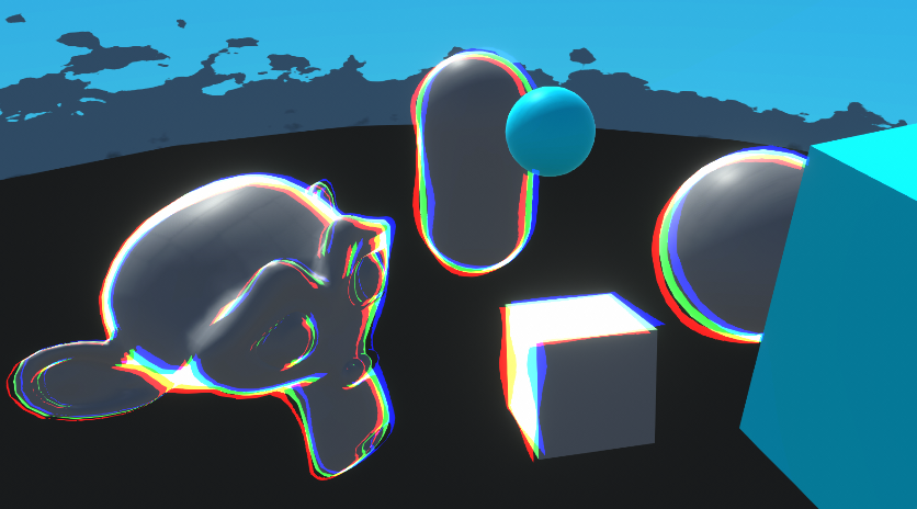
currently working on a custom shader that i'll use so sprites get affected by 3d lighting, i'm trying to flip the normals of the object if the displaying face is the back face

but i cant seem to attach "Is Front Face" to the predicate in the branch
despite the fact that its a bool?
i'm a bit confused
i'm basically trying to avoid this behaviour where if i flip a sprite on the x or y axis the lighting gets all wonky
I'm getting an error about not including INTERNAL_DATA.... but it's included?
            struct Input {
                float3 worldPos;
                float3 worldNormal;
                INTERNAL_DATA
            };

            void surf(Input IN, inout SurfaceOutputStandard o) {
                // Calculate the triplanar weights based on the world normal
                float3 weights = abs(IN.worldNormal);
                weights /= dot(weights, 1);

                // Sample the textures using the world position scaled by _Scale
                float3 uvw = IN.worldPos * _Scale;
                float4 tex = 0;
                float3 nrm = 0;
                // Use the grass texture and normal map for the top plane
                tex += tex2D(_GrassTex, uvw.xy) * weights.y;

                nrm += UnpackNormal(tex2D(_GrassNormalMap, uvw.xy)) * weights.y;

                // Use the rock texture and normal map for the other two planes
                tex += tex2D(_RockTex, uvw.yz) * weights.x;
                tex += tex2D(_RockTex, uvw.xz) * weights.z;
                nrm += UnpackNormal(tex2D(_RockNormalMap, uvw.yz)) * weights.x;
                nrm += UnpackNormal(tex2D(_RockNormalMap, uvw.xz)) * weights.z;

                // Output the final color and normal
                o.Albedo = tex.rgb;
                o.Normal = nrm.rgb;

            }
You can only connect the Is Front Face node to the Fragment stage. For a Lit Graph there will be a Normal port there too, either in Tangent or World space (depending on the Normal Output Space set under Graph Settings).

does anyone know how to apply fullscreen shaders only on tagged gameobjects?
Need to use alpha clipping (at least in the ShadowCaster pass)
yes, dude. How can I do it?
HLSL or Shader Graph?
Would be clip(alpha - threshold); in code
Fragment shader
UsePass "Legacy Shaders/VertexLit/SHADOWCASTER"
Built in shader
I have shadows for sprites but it uses meshes not sprite alpha
You'd need to copy/rewrite the ShadowCaster rather than using a UsePass
Unless it already implements alpha clipping with keywords / specific property names
A fullscreen quad/tri is always fullscreen. You can render specific objects into a render texture and use that in the fullscreen shader to mask it though. Or use stencils. Or just render the shader effect while drawing the objects/meshes themselves. Depends on the effect.
So, there is no way to handle it without rewriting ShasowCaster?

GitHub
Various shaders. . Contribute to przemyslawzaworski/Unity3D-CG-programming development by creating an account on GitHub.
Could try using the AlphaTest version of the shader Unity provides. Imo it's easier to just copy the pass into the shader though.
UsePass "Legacy Shaders/Transparent/Cutout/VertexLit/ShadowCaster"
(That expects _MainTex, _Cutoff and _Color properties)
I want sprite order
They are transparent
ZWrite Off
I mean use the ShadowCaster from it, not swap the entire shader
I get pink one
UsePass "Legacy Shaders/Transparent/Cutout/VertexLit/ShadowCaster"
Oh, seems the pass name does need to be all caps. So SHADOWCASTER instead.
It does not differ dude
:/
UsePass "Legacy Shaders/Transparent/Cutout/VertexLit/SHADOWCASTER"
Again pinky
Do you know a good tutorial on how to use unity’s custom render feature?
Apparently it's named "CASTER" 😞
If that still doesn't work you could just copy the Pass manually.
https://github.com/TwoTailsGames/Unity-Built-in-Shaders/blob/6a63f93bc1f20ce6cd47f981c7494e8328915621/DefaultResourcesExtra/AlphaTest-VertexLit.shader#L128

I have a post on writing custom features for URP 2022 - https://www.cyanilux.com/tutorials/custom-renderer-features/
Goes through examples of Renderer Features and explains how to write Custom Renderer Features and Scriptable Render Passes for Universal RP

Thanks, but it does not work
It is like //UsePass "Legacy Shaders/VertexLit/SHADOWCASTER"
UsePass "Legacy Shaders/Transparent/Cutout/VertexLit/CASTER"
You'll need the properties it expects - _MainTex, _Cutoff and _Color
_Color ("Main Color", Color) = (1,1,1,1)
_MainTex ("Base (RGB) Trans (A)", 2D) = "white" {}
_Cutoff ("Alpha cutoff", Range(0,1)) = 0.5
Make sure you have these in your Properties section
Really appreciated 🙂
Is there a way to make a procedual wave in shader graph, that wraps around a circle?
Something like this?

Oh, somewhat. Do you see my profile picture? Im trying to make waves go up and down within the circle, serving as a sort of audio visualizer. Not actually representing the frequencies, just a general move whjen sound is played
Ive been trying to achieve this effect for ages, but I never really manage to. My shader graph knowledge is limited, and I have no ide ahow complex it would be to get that
Can add/multiply Time outputs in at a few parts to add some movement or use float properties then control those from C# (probably needed if you want to match it to audio). But yeah, sounds pretty complex.
I dont suppose I could DM you, to ask you sometimes for help? if not thats obviously fine lol
I don't do DMs
How to have the texture/color on the backside of my object instead of transparent?
You need to use a shader that has back-face culling disabled (Cull Off in code, or RenderFace : Both in Graph Settings for ShaderGraph)
And where do i find it?
If you're in the Built-in Render Pipeline, afaik Unity doesn't provide one but if you google "double-sided Standard shader" you'll probably be able to find one.
If you're in the Universal Render Pipeline, the URP/Lit shader should already have a Render Face dropdown.
Youre right for urp, but i switched to builtin, i searched in the asset store and i found only one asset, and i tried and it added my back texture but it ruined my front texture by moving it
        private RTHandle source;
        private RTHandle depthRenderTexture;
        private RTHandle colorRenderTexture;

        public override void OnCameraSetup(CommandBuffer cmd, ref RenderingData renderingData)
        {
            source = renderingData.cameraData.renderer.cameraColorTargetHandle;

            RenderingUtils.ReAllocateIfNeeded(ref depthRenderTexture, colorDesc, name: "_PDepthBuffer");
            RenderingUtils.ReAllocateIfNeeded(ref colorRenderTexture, colorDesc, name: "_PColorBuffer");
        }
        public override void Execute(ScriptableRenderContext context, ref RenderingData renderingData)
        {
           cmd.Blit(source, colorRenderTexture, colorBufferPixelizeMaterial);
           cmd.Blit(source, depthRenderTexture, depthBufferPixelizeMaterial);
        }
When my mouse is pointing at a material of spriterenderer or meshrenderer in the inspector i get assertion failed error. I removed the blits in the execute function and noticed the error was gone. I am guessing that it is because of the source, since i am getting cameraColorTargetHandle. How can i prevent this from happening?
Is it because the feature is running in inspector previews? I usually prevent that with if (renderingData.cameraData.isPreviewCamera) return; in the AddRenderPasses method.
https://www.cyanilux.com/tutorials/custom-renderer-features/#addrenderpasses
Thank you so much! Exactly what i was looking for. Solved the issue
if an object already has a material, how do I add a shadergraph material ontop of that instead of replacing it?
There isn't really a way to do that
so if I want to put an effect over a material I have to take in the old material / texture as a variable? :c
If the effect is used a lot, you could have multiple objects share the shader with the effect, only turned off via a property until needed
Otherwise I might swap the object's material to a material instance with the effect and pass properties like texture and color with a script
I'm just trying to learn more about shaders
I'm just thinking about how I would do some things in shadergraph (or HLSL if I get into that) like a character having a dusty effect overlay over their basic skin and clothing material
I expect you could lerp the base color to a dust texture, perhaps masked by a mask texture and/or object normal vector
- also lerp the metallic and specular values
that's 1 effect, what if I want multiple? xD
Same deal, you'd have to either include them all in your shader at the risk of making it costly, or making more shaders to use with the replacement script
It's technically possible to do another shader pass on the same submesh but from what I understand that's not recommend for performance or workflow reasons
noted, i'll see if i ccan manage to fix this
i'm having multiple difficulties getting this to work properly
https://youtu.be/764si-ArcIU
idk if it means anything but i'm trying the fix stated here
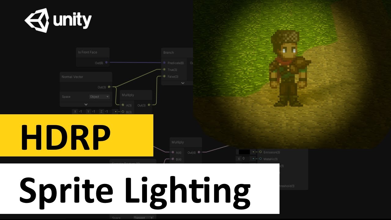
In a short follow-up to my previous tutorial on Sprite lighting, I'll show you how to achieve the same effect with the Unity's HDRP.
Standard Renderer Shader - https://youtu.be/flu2PNRUAso
Follow me and my game "Destiny Break" on Twitter - https://twitter.com/SayAllenthing
Sections:
Intro: (0:00)
Lighting Sprite: (0:18)
Fixing Backfaces: (1:2...
i'm using URP for the render pipeline in this case
the issue is basically that one of the faces of my sprite if i set the render face to both end up with some weird lightingn artifacts
if anyone knows a good fix for this i'd be much obliged, because i'm in a bit of a roadblock rn
i think it might indeed have to do with the normal of the object on the fragment stage as Cyan stated
but no combination of normals and isFrontFace is working
ok nevermind, this does actually work, i can rotate the sprite object and it keeps its correct look

altho now flipping the sprite causes both sides to have the wrong color, which iirc is just because the scale is set to -1
i'll take this win for now, but if anyone knows a good way to fix this now i'd be greatly obliged
https://i.gyazo.com/ee4e2471c272e6b75e03f0a69b38bbaf.mp4
I was thinking about getting the Object's scale from the Object node and do some comparasions if the scale was negative, but idk how to do that
@regal stag How would I use a layermask to write to a texture via a custom render feature only objects with the tag to the texture?
Oh yeah that's pretty interesting, I think I've ran into a similar issue but when it comes to 2.5D you usually billboard your stuff so it's always rendering the front
You can pass a LayerMask into the FilteringSettings struct used by the ScriptableRenderContext.DrawRenderers function.
what does the function do?
.
thats what i plan on doing, i was also planning on doing what doom does (ie: flip a sprite on the x axis) so i can just do 6 sprites, front, back, side and corner views
and then flip the side and cornver views for the other missing sides
what do I do?

Hello, I'm trying to load a texture located in my streamingasset folder in linear colorspace using UnityWebRequestTexture
I've read I just need to use ImageConversion.LoadImage(tex, tex.GetRawTextureData()); to convert from sRGB to RGB
This texture is channel packed with albedo in red, normal x in green, normal y in blue and alpha in alpha
When loaded, it appears the colorspace is still not set to linear.

When I put this texture in the root asset folder and disable sRGB in the texture importer, I get this

Which is correct and when I replace the web texture by the one from my asset folder, I get the desired result.
How can I get my UnityWebRequestTexture loaded texture to be the same as the texture importer ?
Ok, to answer my own question, it appears I was using the wrong bytes[] source.
It's working fine with ImageConversion.LoadImage(tex, uwr.downloadHandler.data);
how do I get tesselation factor as an option in my shader graph? I'm following this video that has it in the vertex space but I'm not sure how to get it for myself

It's currently in HDRP only
can it be done in another way outside of hdrp
Not really for Shader Graph, but can add tessellation to shader code
For Built-in RP can add tessellation to surface shaders - https://docs.unity3d.com/Manual/SL-SurfaceShaderTessellation.html
Or for vert/frag style shaders (which would also work in URP) - https://catlikecoding.com/unity/tutorials/advanced-rendering/tessellation/
thought so. not very experienced in shader code yet unfortunately
How to achieve something like this
Ignore that skull

Should I do gradient node then split alpha?
I guess that could work, if its 3d it looks like a cylinder to me with a gradient
Well, my object is cylinder without top and bottom
nice
Hey can can someone help me

i wanna create outline shader
like in tutorial
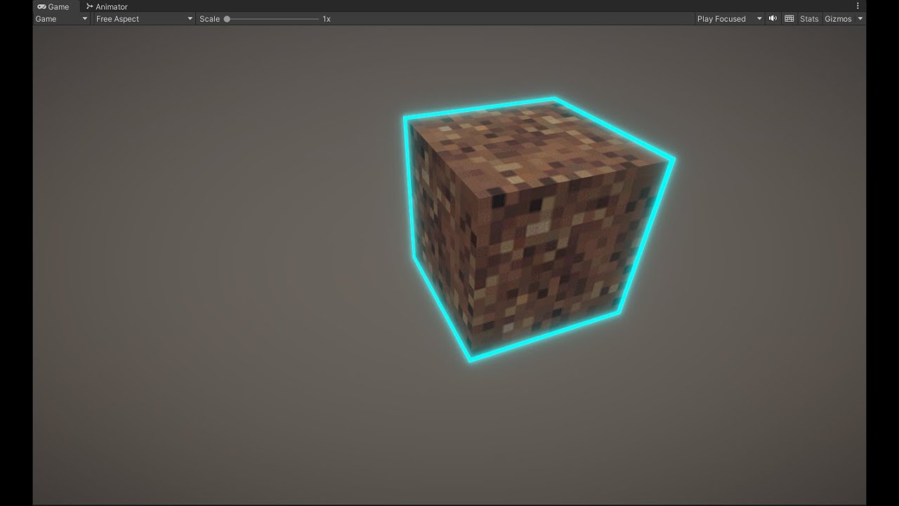
i have my own object
heart
this is how i set my shader


when i apply it on object it doesn't do anyhting

What do you mean? In the viewport it works
maybe save your shadergraph?
oh wait
you have 81 set as your scale
thats way bigger than your object
probably want to reduce that
also, if your normals are smooth you should base your outline on normals
and not scale up the object
It's from video
void Unity_ColorspaceConversion_RGB_HSV_float(float3 In, out float3 Out)
{
    float4 K = float4(0.0, -1.0 / 3.0, 2.0 / 3.0, -1.0);
    float4 P = lerp(float4(In.bg, K.wz), float4(In.gb, K.xy), step(In.b, In.g));
    float4 Q = lerp(float4(P.xyw, In.r), float4(In.r, P.yzx), step(P.x, In.r));
    float D = Q.x - min(Q.w, Q.y);
    float  E = 1e-10;
    float V = (D == 0) ? Q.x : (Q.x + E);
    Out = float3(abs(Q.z + (Q.w - Q.y)/(6.0 * D + E)), D / (Q.x + E), V);
}```
I am having a problem with unity's colorspace conversion formula. The problem is that when Value is zero, Saturation also becomes zero. This is causing bugs further down the line that expect a saturation of 1 when the color value is on the fully saturated side 🤔I havent found some way to fix the bug, and forcing the value to be nonzero is only causing even more bugs in different places
or something? I'm poking and prodding but I can't seem to figure out where this color problem is coming from, somehow red is becoming not red and its so frustrating to debug because I can't just extract a @#$@^ float balue from the red channel to tell EXACTLY how much and where its coming from 💢

Gist
"Print a value" custom function node code for Unity ShaderGraph, aware of +Inf/-Inf and nan - DebugNode.hlsl
I found this online
be productive instead of angry 
How do i add a valid keyword? If I change size, it increases the size of invalid keywords instead

Or is there any other way to set these shader keywords in unity 2021
Oh, I got it
These keywords just appear in the material properties
Hello,
I'm making a shader with a top-down world space texturing.
It's quite a simple one, but I am missing something and my normal maps look wrong.
I assume there is an easy way to fix it, but I simply don't know how.
Can anybody help?

Assuming it's the typical tangent-space normal map (the bluish ones), ShaderGraph will transform that from tangent into world space using the tangent & normal vectors stored in the mesh data. Those tangents are aligned to the mesh UV0, hence why it might look wrong when using different UV coords.
I think in this case you can just Swizzle the "tangent" space normal (RGBA result of the Sample Texture 2D set to Normal mode). "xzy" should work.
For a Lit Graph, under the Graph Settings you'd change the "Normal Fragment Space" to "World" then connect your output to the "Normal (World Space)" port in the Fragment stack.
@regal stag that actually works! Thank you so much!
having foilage render both faces only checks if the sun hits on one side forcing me to have it rotated towards the sun to look right, and i think having duplicate faces (giving each grass like this 8 quads total) would be kinda costly with the wind shader? what can i do about this?

I can't really have it rotate toward the player because plants like the one on the right needs to be static
Also just having it be unlit would make it look glowing in shadows
In shadergraph you can use the "is front face" node to selectively invert the normal for the back faces
I saw someone do something like that on the unity forums (image), but shadergraph doesn't let me do what the image shows

You're not trying to connect it to the vertex normal are you ? 🙂
oh, i might
Would look like this in newer SG versions, in case that helps

I don't think you have to set the fragment normal to world space, tangent should still work
If you also set the "normal vector" to tangent of course
- keeping tangent makes it easier to work with imho
I'm using unity 2021.3 so I'm on a bit older version, my fragment doesn't have as many nodes
For tangent you only want to flip the Z I think. https://www.cyanilux.com/faq/#sg-two-sided-shading
Hum, that depends if you "flip" or "mirror" the normal
But yes
Yeah I meant negate, not one minus
Found that i can add blocks to the fragment node, but they grey out what i connect to them

It looks like you're using an Unlit graph
Should be able to switch to Lit in graph settings
oh wow, oops
Unless a normal map is used wouldn't it being in World space be cheaper though, since the tangent->world transform isn't needed 🤔
I guess it is easier to swap out later if you want to add one though
Yes, this is what I had in mind
Hey, I was wondering if someone could help me. I've created this shader. It's suppose to put the gravel texture on the bottom of the Object. But right now it's set on goble coordinates, so it doesn't proplery work on on other objects which don't share the same height level as this one. But if I change the Position node to object space there is only one texture shown

I'm new to this would be great if some could help
Anybody familiar with the Unity Shaders Bible? I've been working through it and have a question about a specific section about rotating the UVs. Not sure if it would be acceptable to post like 3 or 4 pages from the book, so if someone else has it and can look up the page numbers I've got questions on that would be helpful!
I haven't used transparent meshes much, usually only opaque, are there any good resources of breakdowns of what all the values mean and do? I am currently reading https://www.cyanilux.com/faq/#transparent-sorting and learning its non-trivial 🤔

For example, does any of those parameters mean 'render all of the faces, no culling anything' ?
Hello
Im trying to figure out how to write shaders for the new FullScreenPass Render Feature in 2022LTS. With the old way of writing a custom render feature we could use any old unlit material and it would just work. So something like:
Shader "Unlit/Test"
{
    Properties {
        _BaseColor ("Example Colour", Color) = (0, 0.66, 0.73, 1)
    }

    SubShader {
        Tags {
            "RenderPipeline"="UniversalPipeline"
        }

        HLSLINCLUDE
        #include "Packages/com.unity.render-pipelines.universal/ShaderLibrary/Core.hlsl"
        ENDHLSL

        Pass{
            Name "ColorInversion"

            HLSLPROGRAM
            #pragma vertex ColorTestVert
            #pragma fragment ColorTestFrag

            struct Attributes
            {
                float4 positionOS   : POSITION;
                float2 uv           : TEXCOORD0;
                float4 color        : COLOR;
            };
            struct Varyings
            {
                float4 positionCS   : SV_POSITION;
                float2 uv           : TEXCOORD0;
                float4 color        : COLOR;
            };

            float4 _BaseColor;

            Varyings ColorTestVert(Attributes IN)
            {
                Varyings OUT;

                VertexPositionInputs positionInputs = GetVertexPositionInputs(IN.positionOS.xyz);
                OUT.positionCS = positionInputs.positionCS;
                OUT.uv = IN.uv;
                OUT.color = IN.color;
                return OUT;
            }

            half4 ColorTestFrag(Varyings IN): SV_Target
            {
                return _BaseColor;
            }
            ENDHLSL
        }
    }
}
Gives the expected output of a cyan screen when tested with Cyanilux's blit render feature. But if i use the same material with the new FullScreenRenderPass it wont do anything.
I know that the shader is running because the frame debugger shows the that it was used

Ztesting Always means it will not cull based on the depth buffer
cont.
i added another FullScreenPass which comes with a default color inversion material attached and noticed it was using _BlitTexture.

so i added that as a property to see if that had any effect
Shader "Unlit/Test"
{
    Properties {
        _BaseColor ("Example Colour", Color) = (0, 0.66, 0.73, 1)
        _BlitTexture("BlitTexture",2D) = "white"{}
    }

    SubShader {
        Tags {
            "RenderPipeline"="UniversalPipeline"
        }

        HLSLINCLUDE
        #include "Packages/com.unity.render-pipelines.universal/ShaderLibrary/Core.hlsl"
        ENDHLSL

        Pass{
            Name "ColorInversion"

            HLSLPROGRAM
            #pragma vertex ColorTestVert
            #pragma fragment ColorTestFrag

            struct Attributes
            {
                float4 positionOS   : POSITION;
                float2 uv           : TEXCOORD0;
                float4 color        : COLOR;
            };
            struct Varyings
            {
                float4 positionCS   : SV_POSITION;
                float2 uv           : TEXCOORD0;
                float4 color        : COLOR;
            };

            TEXTURE2D(_BlitTexture);
            SAMPLER(sampler_BlitTexture);

            float4 _BaseColor;

            Varyings ColorTestVert(Attributes IN)
            {
                Varyings OUT;

                VertexPositionInputs positionInputs = GetVertexPositionInputs(IN.positionOS.xyz);
                OUT.positionCS = positionInputs.positionCS;
                OUT.uv = IN.uv;
                OUT.color = IN.color;
                return OUT;
            }

            half4 ColorTestFrag(Varyings IN): SV_Target
            {
                return _BaseColor;
            }
            ENDHLSL
        }
    }
}
it didnt, the texture never even got set according to the frame debugger
any guidance would be appreciated
The easiest way is to use the new Fullscreen Graph as that feature is written with that in mind.
But if you do want to use shader code, the vertex shader can't use the regular object->clip conversion with the Fullscreen Feature. You should include Blit.hlsl (#include "Packages/com.unity.render-pipelines.core/Runtime/Utilities/Blit.hlsl"), and use the vertex/fragment programs there or copy & edit them.
https://github.com/Unity-Technologies/Graphics/blob/master/Packages/com.unity.render-pipelines.core/Runtime/Utilities/Blit.hlsl
oooh i see! thank you ill give this a read
hmm tho im still confused as to why that would affect the texture being used or not?
It's basically because you'd be applying the camera view/projection matrices, and Unity isn't overriding those like it does with cmd.Blit. So the triangle rendered by the Fullscreen pass probably ends up at the scene's origin rather than attached to the screen.
wouldnt it still show up in the framedebugger tho since its being used?
The Fullscreen feature is still showing in the frame debugger isn't it?
If you aren't using the texture in the fragment shader it's probably being removed by the compiler though
oh i see yea thats what i was curious about. Thats why it isnt showing the texture in the debugger
thankyou that clears things up!
lit/universalpipeline doesnt work and whenever I adjust the slider it goes transparent and I cant see it
I used pp double sided and it works fine, but I want to use lit for the lighting because it looks better


AHHHHH found it
its fine ignore it
I am working on a transparent plastic shader and hitting some early snags I'm not sure how to resolve 🤔 All the blending modes and alpha I've tried using have the same problem - the more front/back faces the mesh has, the more opaque it becomes which is directly opposite how it works in real life where material's thickness is what builds up opacity, and not the number of faces passed through
Can new Blending Modes be written and added to shadergraph, beyond Multiply, Additive, Premultiplied Alpha, Alpha?

I am using a lego brick as my reference material since it's the only example of the kind of transparent material look I am shooting for that I have easy to find practical examples to compare against
You're trying to do one of the hardest challenges in realtime rendering.
Even with raytracing in HDRP it's hard af: https://youtu.be/Xh_b9WDfZ-s?t=962
Hm good to have the context that this is extremely non-trivial. I did see this video while googling, he says they wrote SDFs of the meshes and raytraced those, which makes sense since lego shapes are relatively simple and easily described by math
hey,
i keep getting this error that is pointing to a commented line
Shader error in 'Test/TestShader1': Unterminated conditional expression. at line 378

Compiling Subshader: 0, Pass: <Unnamed Pass 0>, Vertex program with <no keywords>
line 378 is a comment and when I remove it it just pick another line ( sometimes commented and others are not ) and just throws errors that doesnt make sense, what is that ?
could you send full code?
Hello,
I am looking for some tutorials about writing shaders in Unity but not with ShaderGraph. I have experience with Godot shaders, and I managed to translate most of my shaders to Shader Graph but the node system makes everything very messy and hard to follow. Especially with more complicated shaders.
Can anybody point me to some good resources for learning shaders for URP in unity in the traditional way?
Based on the error description I'd expect it's maybe to do with a #if/#ifdef that doesn't have a corresponding #endif perhaps.
I've got an article, https://www.cyanilux.com/tutorials/urp-shader-code/ for writing vert/frag shaders in URP and some examples https://github.com/Cyanilux/URP_ShaderCodeTemplates
Writing Lit shader code currently is a bit complicated. Unity is also working on "block shaders" (essentially the SRP replacement for surface shaders), so be aware you may have to relearn stuff when that's released.
Is the Rider Unity extension might to provide auto-complete, tab completion etc. for shaders? Mine recognises when I have typed out a reserved keyword, but that's about the extent of any IDE features I get when writing them out
Rider should provide you with things like that
Hmm, I guess a good'ol uninstall reinstall is in order
How can i make such kind of shaders? is there any tutorial for this type of games

There are likely multiple at play. Any object in specific?
how can i make the lines left by the trailrenderer stay flat on the ground?
idk if i put this here or somewhere else
rn im just turning on or off the emitter based on if the drift key is being held down
I would go as far as say that these shaders are pretty much identical to what Unity's built-in PBR shaders can do; what is more interesting here is the lighting that achieves this effect
(there is also some kind of line detection on the sides etc but I'd say that's separate)
this example mainly looks like some untextured meshes with a standard PBR shader with some smoothness and baked lighting (including GI and reflection probes)
helloo I need a little URP shadergraph help
I have a shadergraph that applies a texture to an Image, and I need the texture to display independent of the Image's scale. Do I need to scale the SampleTexture2d somehow?
see here the same material/shader applied to different images of different scale. I want the texture to appear the same scale behind both of them

You can get the scale of the object in shadergraph to use this.
Otherwise use world position (maybe with the object node to get the position as an offset)
I tried setting the tile based on the scale from the object but that didn't work so not sure if I did it wrong
You gotta share the graph if you need help with that

In the image I don't have anything connected to the tile node
Because I couldn't get that to work
could someone help understand why the left-hand texture looks brighter than the right-hand one?
the latter is an actual Texture2D put together using a Photo-Editing software, while the other is supposed to be an identical copy of it...
the process of making a clone is done via a C# script -> https://paste.ofcode.org/GyHybyDrkjEREFHEVqzwbf
that sets the originating values to a User-Defined shader -> https://paste.ofcode.org/HR3KmbPub5GsczVUWrd6Yh (it's an Unlit shader),
where there's a predefined amount of range properties (48 one), each 3 representing the RGB channels of a given color, all channels range from 0 to 255.
byte values conversion is done by dividing range by 255F aka:
// NOTE: `uint` instead of `byte` since there's no such data type in ShaderLab.
float ByteToFloat(uint value) => value / 255.0;```
is the above function the reason why the end result isn't quite as accurate?
and if so, what else am I recommended to do?

otherwise, could you hint me where am I making the mistake?
I think it is just some gamma correction applied : try to power your float value by 2.2 or 1/2.2 (I can never figure out what way it is) to convert linear -> sRGB or inverse.
Maybe look up triplanar and use that?
Or hook up scale somewhere with the tiling and offsets
the correction made:glsl float byteToFloat(uint value) { return pow(value / 255.0, 2.2); }
the new end result:

sex!
You could also use the screen coordinates as UV input for the hash texture
@ocean orbit To put it short, retrieving an arbitraty value of a pixel from a shader is not an easy task. Why do you want to do that specifically ? What is the intend ?
In fact it's useless, I built a complex shader to generate a map more easily but now I need the result in a c# script. But as realize I won't need this shader as a shader I have to convert it to C# it will be better...
You could render the shader to a texture, and read the individual pixels from this texture afterwards
Storing height/biome/color .... whatever values you want in the 4 available color channels
By using layers it is possible
Or command buffers, but that's a bit more advanced
It's culling mask ?
Yes
Thanks I'll try
Hello, I am trying to make a procedural skybox using shadergraph but I keep getting seams in the skybox like these:

I have looked online and although their are solutions to smilair problems none of the results create a seamless skybox
Can you share a screen of your graph ?
right now its only a gradient noise attached to an unlit shader base color
just so i could screenshot to show

Building a flexible procedural skybox shader in Shader Graph for Unity's URP! We'll be tackling sky colours, stars, a sun/moon, clouds and fog!
here is an example solution I found but even it doesnt solve the problem
The gradient noise is using a 2D coordinate input, and output a 2D noise, for nice 3D noise you would need a 3D verison of it, with 3D coordinates input (view direction i.e.)
Or use some form a triplanar mapping.
As for the small white seam in the middle of your image, I think it is cause by the UV inversion resulting in undefined noise value ? Or maybe the noise is not so great and is just white at the edge, try to offset a bit the UV value.
- I need to make options for shaders, which is usually done with toggles, #ifdef and pragma. Can this be applied to enum field as well? I.e. can i check for specific entry of an enum field with ifdef, or should i work this around with N toggles and custom inspector to hide them behind the enum field?


Here's some more pictures
I'm having trouble in general understanding how uv mapping works mathematically in shadergraph
but its resulting in things warping in ways I dont think they should be
Use KeywordEnum attribute ! 🙂
https://docs.unity3d.com/ScriptReference/MaterialPropertyDrawer.html
The graphs you've showed transform world 3D coordinates to a 2D lat/long projection and use it to generate a vornoi noise.
Figure out an earth map (unless you're from flat-earth society) wrapped to the globe.
But the issue is that the voronoi noise doesn't wrap, so left edge of the map doens't match the right one
Hello, I am trying to get a Vignette effect but for some reason, the shader doesn't take the colour I assign. Here is the script: https://hastebin.com/share/sedojabeku.cpp
This is what happens when I give it red. I want the white part to be red too

Hastebin is a free web-based pastebin service for storing and sharing text and code snippets with anyone. Get started now.
Try saturating vignette
How can I do that? I have never written a shader till now 😔
vignette = saturate(vignette)
Like this? Nothing happened

Yes. Nothing changed? You definitely saved? I can't think of what else could cause it. What happens when you use _VignetteColor.rgb instead of the whole lerp, do you get the color you expect?
It's because most shader functions are unclamped. Saturate is clamp01 for shaders
So what was happening is that on the edge of the alpha where lerp was 1 the color was perfect, but after that it interpolated past and went into white and hdr colors
How would I go about making a skybox shader with no horizon? I am trying to make a procedural skybox which is all made of stars but am having trouble uv mapping it and texturing it without stretching.
Ahh makes sense, thank you
- I get this shader error while the indicated line is completely empty. Googling didn't help. What could it be?


upd: it turns out parethesis was the cause. Solved
so, i just create compute shader to spawn mesh, but instead of activate it right away i spawn it later using unity timeline, but it always crashing the unity editor, already tried to decrease the spawn to only 100 mesh but it still crash (i use simple sphere from unity as a mesh)
anyone know other solution?
- Regarding this. I used keywordenum and now try to set this property through code to change the shader's behaviour, but it doesn't work. Am i supposed to de/activate keywords manually?
Kind of yes : The keyword update is done within the material inspector, meaning that if you change the float value from code, it will not propagate to the keyword.
Also, in builds be sure to have the shader variants with the keywords you need compiled, else it will not work
- How can i make sure that i have these?
The following HLSL code, which works fine in URP's Forward rendering, produces flickering in Forward+.
What do I have to change to correctly read light data in Forward+?
int pixelLightCount = GetAdditionalLightsCount();
for (int i = 0; i < pixelLightCount; ++i)
{
    Light light = GetAdditionalLight(i, WorldPosition, 1);
    // light.color flickers
}
I think you need to use some additional defines and macros.
Look at how Cyan did it here : https://github.com/Cyanilux/URP_ShaderGraphCustomLighting/blob/main/CustomLighting.hlsl#L211
Thank you, I'll try it out 
This render texture doesnt work on mobile 🥲
It's just a blank white image
- One more thing: do i need to include this collection somewhere, like shaders in project settings? Or just creating and letting it be is enough?
I forgot to mention that if you used multi_compile it will force compile all the keywords, so no need for the collection
But if you use shader_feature that's when it can be striped
Else ... Hum doc is definitively fuzzy on this, but I think that adding the collection asset in the resources folder is enough
Hello, I'm having an issue with my model where it simply won't show in play mode.

But in preview mode, the model loads fine

Out of the 15 hair styles I've imported, 2 of them have this problem.
I use the same method to import all of them so I can't figure out why 2 of them simply don't work :x
When I add it directly in the scene, it seems to work??

I've checked the position and scale to make sure I didn't mess up. I also ticked the "Update when Offscreen" jsut in case but still nothing.
I've tried replacing the instanced materials by the original ones but still no luck
Any ideas what could cause the problem?
It's also not a problem with fully transparent color
Slight question because I don't know how this channel/the server feels about it.
Thoughts on reverse engineering a shader?
Ror2 (2019.4) has a shader that it uses to draw damage numbers on the screen using a particle system and a shader, been thinking about trying to reverse engineering that for my game
I can give more details on what I know, assuming reverse engineering is ok, lol
The shader itself has a texture (where in the case of ror2 it's a sheet of 4x4 distinct symbols (0 1 2 3 4 5 6 7 8 9 KMB!)). And it has a color parameter for tinting, tinting the final results is easy since that would be just multiplying the color with the texture
The issue arises at how it would build the numbers, it uses the particle system's custom data module to give it a Vector4 of values, 0, 1, damageAmount, b where damageAmount I'd the final number that gets displayed on the material and b wether or not it should re-multiply with a "critical" color for critical his
I am unsure if this would be possible to recreate using shadergraph nodes
The Flipbook node should help with this. It selects a portion/tile of a larger texture
If damageAmount is for example, 132.45f, the displayed value is just "132". For bigger numbers, if it's larger than a thousand, it uses the first three digits and appends a K, larger than a million, it uses the first three digits and appends an M
I was actually thinking on using the flip book node, tying an index to a specific symbol is the easy bit and I figured that out
The use came with reconstructing or stitching different numbers
Mainly because afaik there isn't a way to like, "move" the pixels taken from the flip book node
Or resize them
Neither something that would allow stitching, with nodes that is
Was thinking about doing this as a shader because well, it's extremely performant as it's just on the GPU side, and doesn't Involve objects at all appsrt from a single manager that has the particle system itself
There's some "debug value/int" subgraphs for ShaderGraph which can display values like this, might be able to look at how they work. Though you'd need to adapt it to be able to display K/M. Can probably use some comparisons.
e.g. https://github.com/RemyUnity/sg-node-library/tree/master/Runtime/Nodes/Debug
Though it might be easier to just use something like TextMeshPro.
Ohh, nice
I did see some debug ones for regular hlsl
Didn't know there where ones for just shadergraph
Oh definetly, but I do think getting this would still be beneficial as a while
Specially if I make it open source and MIT later 
The only issue I'm aware is that this doesn't work with split screen, but that doesn't matter since my game is single player only
Why wouldn't it work for split screen? 🤔
oh, sorry i mean the "particle system" aproach
idk how the server as a whole feels about unity game modding, but as a hobby i like to mod ror2, which is why i know fairly well how it's aproach works, appart from the shader since there is no way i could decompile it or see how it works due to limitations
at least in ror2 modding, splitscreen coop mods fail to properly render the damage numbers, i dont know why personally
another reason why i wouldnt want to use just textmeshpro is because there is no text mesh billboard shader
so to make it feel like one i have to constantly call lookAt the camera object
which again, is more strain on the cpu

thats bloody massive

well it does work
thanks for the insight @regal stag
i'll see what i can cook up

Just trying to apply very simple textures... and running into this.. I want it to map over the entire surface, but some object it seems to just go, "nope"... The object is single mesh
Should look into "UV unwrapping" in whatever modelling program you used to make the mesh
Ok, it was Blender and I looked at teh Normals... the texture was applied in Unity
....anyone?
anybody using toonchan? i wanna add some vertex displacement, so i thought of copying some shadercode, so it still fits with the environment
ahh i forgot that you can get the coed from shagraph, this way i cann add it easily to the toonchan shadercode
You already got the answer, the UVs are the issue here
Thank Ole.... I'll need to read more into UV mapping I suppose, perhaps you can give me a leg up though? Are we talking the UV Mapping for the object in Blender? As far as I knew, the object is just a mesh in Unity... which is where I was applying the texture
yes, the UV map of a 3D object determines how a texture is applied to it, regardless of the software
The UVs are part of the mesh data
Hi,
I'm using a shader for raising mountains, but the meshes are not uniform in shape
From the Y axis, how do I make it so the vertices closer to the borders are less influenced, until the very edge is a Y of 0?

side image for clarity. I'd want the edges to be touching the tile beneath.
Alternatively I'd be willing to do the same by just editing the mesh itself (in code), but again, I'm not really sure how to determine how close to an edge the vertex is as it's not a uniform shape and each mesh used for mountains can be a different shape

this shiny map
and also like this map and objects

I am newbie in unity i want to make this style games
Searching for a tutorial to create scene like the image i sent
Thank you for clairifying!
is there anyway to create tessellation in shadergraph urp?
Hey guys, I'm wondering how I'd shift the color palettes of some basic materials textures using shaders.


Ideally it would go from 1 to 2 to 3 interchangeably with some smoothing/interpolation.
I'm currently using built in render pipeline, but I'm down to switch to URP to get the job done.
I just have no idea where to start: Complete beginner with shaders.
Create a texture the same size as that "island" or whatever it is....the stuff inside that orange outline.
Using a paint/texture editor, create it such that you have a MASK texture that represents the scale values you want...for example white in the mostly-center areas, tapering off to black at the edges. Use blurs, gradients, whatever to create this.
Assuming it is UV mapped to your island, use that texture to scale the offsets (multiply).
You might also manually calc it using a distance field, assigning distance from center values to the mesh verts.
I've seen people saying they're using heightmaps and such on their maps. But, for the level of detail needed for the gradient, would the texture not need to be quite large?
Lets assume the map is 100x100 hexes in a rectangular format, with the top left being UV 0,0 and the bottom right being UV 1,1
How large should I expect the texture to be? maybe ~30 pixels per square, so 3000x3000? is that reasonable?
I was considering that, the formations are essentially multiple hexes, but the downside is if it's distance-based, it'd need to be the distance from the centre of each hex, which would make calculating the edges that meet in a shader basically impossible, I assume?
The heightmap sounds more plausible, I'm just not sure if I should expect it to be ~3000 squared
(or if there is a more efficient method)
If you're stuffing it into mesh data the last thing you'd want to do is calc that every frame...maybe you could use a compute shader to get it done, and then read the data back, and then stuff in into the mesh in C#, and do that ONCE per change of the mesh. All other frames would just read it.
Or you can do it in C# ONCE and unless it changes, you don't have to calc it again. Don't do it every frame.
Yeah, you're right. I'll probably do it with a heightmap, without the shader for verts. My only issue is going to be that since it's generated terrain, I'll need to figure out how to generate the heightmap texture based on terrain types
(with fading gradients, etc)
Also, if it is a gradient, it might not be too bad to use a smaller texture and let interpolation handle the in-betweens. As long as you get it mapped to the right shape so that the edge pixels match up.
Yeah, so long as the mountains match up in general. The downside is each tile is it's own mesh, except mountains atm. Since most tiles are only 6 triangles, with mountains scaled up in tris, I may just try combining it all into one mesh once generated anyway
Uh, only mentioning this in terms of the edges lining up and normals appearing correct
I think some mobile has a limit of 2048 in both the x and y dimensions of the texture. But that's pretty old hardware. See Unity docs in texture importer.
Yeah, IDK then. If you re-use meshes across hex tiles.
I'll experiment with a heightmap in any case, it sounds like my best bet
If you don't reuse meshes (each is its own unique instance) you can still assign height values to a UV set.
Yeah, each hex is generated in code atm, so they are all unique
I appreciate the replies. Heading to bed, but I'll give heightmapping and altering the mesh verts in c# tomorrow
ok so, i've found a guide on GameDeveloper.com that does exactly what i wanted, which would be making a shader that displays text to use on stuff like damage numbers

Game Developer
A Unity gamedev guide by RocketBrush Studio programmer Timur Gadeev.
i'm working on translating the shader code itself into shadergraph
however, one of the methods theyre' using is UnityObjectToClipPos(), i dont think this helper function is included in shadergraph by default...?
I dont understand your question, but I assume you want to have a different texture for the sides and for the top, if that´s the case, create another material with the texture you want to apply and assign it to the first or second slot of your mesh renderer materials
Hey, I got some shaders and such optimized for android, and they look great in unity, but when i put them onto my meta quest, all the quality goes. Is there a setting I can change to keep the quality as normal?
Wait, I might've misunderstood something, forget it lol
You can get pretty close with the URP lit or simple lit shaders. Just play with the variables
Look up how to make plastic / clay materials/shaders maybe if you want something more custom
Hello, is it possible to channel pack grayscale albedo, normal map (X & Y then use reconstruct Z node) and alpha into one texture?
Reading about it, albedo and trans seem to be in gamma colorspace while normals are in linear, which would prevent them from being packed together?
Or since albedo and trans are both grayscale, would it matter if they are also forced to linear ?
So I've been teting this around. Left node is my not packed normal map. Middle is the combine node getting the green/blue channels from the packed texture. Right node is the reconstruct Z.

From what I see, if Combine has the Z at 1, it gives the same result as the reconstruct node. So does the reconstruct node simply set Z to 1?
Second question, the original normal is more blue-ish than the reconstructed one. Why is that?
The sample is set to "Normal" mode which is remapping the values into a -1 to 1 range, rather than 0 to 1 like the purplish result.
You probably don't even need the Normal Reconstruct Z. You'd usually put it through a Normal Unpack node that'll do the remapping and reconstruct for you
The reconstruct uses float reconstructZ = sqrt(1.0 - saturate(dot(In.xy, In.xy))); though it's possible the normals here are quite subtle so that results close to 1.
You could probably use a Colorspace Conversion node as well to solve the problem of packing color & normals together.
Oh, I didn't know there was such a node. Good to knowindeed
Is it important for the texture file to be tagged as sRGB or RGB for this node to function properly?
It can convert both ways
But does the sampler give a different result if a texture is tagged as sRGB or RGB ?
I'm using a script to pack stuff together and can change the resulting colorspace but I had the impression it didn't affect anything?
I think it does differ but I'm no expert at colorspaces really, they always confuse me
Changing to a normal unpack node does give the intended blue ish but there is some black in the final result strangely.

I was using the wrong original normal texture by the way, I updated to the actual normal one. Actually, I only have a bump map and was using Unity bump to normal feature which seems to give a better result thant the software I use to convert bump to normal. Is there a way to save the Unity converted bump to normal once it's done?
Not sure if there's a way from the inspector, but could probably sample and output the result as Base Colour in an unlit shader, then blit that to a texture. I've got a repo which has some baking stuff - https://github.com/Cyanilux/BakeShader
o.vertex = UnityObjectToClipPos(v.vertex); (or the equivalent) is already handled for you by Shader Graph so isn't something you need to replicate.
Got it, thanks. Any tips for the unpacked packed normal having black colors in it?
That might be why you need a Colorspace Converison before. I'm not too sure.
Got it, thanks
Great! That worked! Not 100% the same result obviously but close enough for my need. Thanks again for your help!

How could I save multiple values in the stencil?
Very cool, there's a bit where it seems like in the shader code it's accessing an indexer for float3, would float3var[1] be just the y component?
And also uhh, what would be the best way to replicate the for loop? Was thinking on doing it in a custom function
Correct, and yes for a loop you'd need a Custom Function node
Depends what you mean exactly. The stencil buffer is 8-bit so can store values from 0-255. But each pass can only write a single reference value, or increment/decrement the current value.
Could I somehow make that two 4 bit numbers?
With ReadMask, WriteMask and some bit shifting, yes.
In a stencil block, you can set the ReadMask and WriteMask to read from and write to only specific bits.
But just note that you can't use the increment or decrement operations on bitshifted numbers.
Or at least, it won't do what you expect most likely, since it will still try to increment with the ignored bits.
Great, thanky you!
I dont quite understand how to calculate anything inside the stencil and pass it on, do you know any resources?
The operations you can do with the stencil buffer are limited to the fixed functions provided to you. You can't modify it with your own shader code (or at least not easily). So it's similar to blending operations or depth operations in that regard. You specify the input variables, like Ref, ReadMask, WriteMask and then you specify what comparison operation to use to compare Ref with the current value in the stencil buffer, then you specify what you want to happen under different conditions. All predefined and limited operations you can do.
Oh, so I cant do the increment part myself?
No
Fixed functions. You can only specify the rules and some input variables, with those rules being limited to whatever some committee at Khronos/Microsoft picked for their graphics libraries decades ago.
But I believe DirectX 12 and maybe Vulkan allows for shader access to read and write to the stencil buffer.
But it also comes with performance overhead, since the hardware can no longer predict what the stencil value is going to be ahead of time.
Do you know how bad it is?
Would there be any other way to achieve something similar that might be better?
Are you sure you need to increment? What are you trying to do with these two numbers?
Should I explain the whole problem I'm trying to fix or keep it short(Just say what I'm trying to do)?
Best to include all the details.
Storing multiple numbers in stencil buffer
uhm, hi, I'm having a problem with compute shaders
I've to find a way to parallelize this thing
element[i].x = element[i].x - element[id.x].x
I have to execute in this way:
when all x threads are finished to execute increment i (i= i+1)
and then execute them again
for calculate the next element[i].x
I think I'm confused about how depth works in URP. I've got a depth only pass (ZWrite On, Cull Off, ColorMask 0, with a frag output) and my actual shader pass. How can I make sure the actual shaderpass is masked by the frag output of the depth pass?
What exactly do you mean by masked? Perhaps you want ZTest Equal in the main pass?
Also are you doing anything to render that depth only pass? You might need a RenderObjects feature
I guess explaining the problem more broadly might be helpful
I'm trying to render hair (which is on it's own object) with transparency (not alpha clipping). I've got the aforementioned depth pass, and my main pass, but in the main pass, which has Blend SrcAlpha OneMinusSrcAlpha, ZWrite On, and ZTest LEqual, and Cull Off the hair renders on top of itself when viewed straight on
(I need to render both sides of the plane)
there's no issue with the hair rendering relative to what's underneath it, just the fact that it "doubles up" on itself
I was experimenting with reading the alpha of the texture during the depth, but no matter what the fragment shader output in the depth, there was no effect (I could return 0 or 1 and nothing would change)
It wouldn't matter what colour value (SV_Target) the fragment shader returns as with ColorMask 0 the target buffer isn't going to be altered.
But you can also write to the depth buffer with SV_Depth. Unsure if that'll help here though really, usually you use alpha clipping for hair afaik.
Algorithm:
- Calculate increment
- Call "GroupMemoryBarrierWithGroupSync()";
- At this point all additions will be calculated. Calculate the rest
It is possible that you will require "AllMemoryBarrierWithGroupSync" function instead, depending on your algorithm.
oh, that's new stuff, I'm gonna take a look to these functions, thanks
I am looking for keywords to help me google search a specific shader effect - URP.
I want to do a sorta 'scrub reveal' shader, as in a position is dragged around which writes to a stencil buffer which is used to then reveal a material. The material I want to reveal is one of Freya's Shapes assets so I can't write a custom material for the reavealed thing itself to take in a texture to use as alpha, so I have to do it in the stencil buffer
What is this effect called? In my mind I think 'some kind of pencil draw shader' but 'Draw' and 'Pencil' have totally different shader connotations, I can't find anything close to what I am trying to do on google
like imagine you are physically manually scratching off a scratch and win ticket, that but to the stencil buffer
https://i.gyazo.com/a696cdb5cc8a5f9a4e8428a50bf994b2.mp4
Well, that isnt precisely what i expected
The closest thing this reminds me to is this:
https://www.youtube.com/watch?v=LnAoD7hgDxw
Doesn't seem related at first, but I think the gradient mask texture is similar to what you are thinking of. However "gradient mask" doesn't seem to be a keyword people use.

In this Visual Case Study, we use shaders to recreate the various screen transitions seen in Pokemon and other RPGs.
Support me on Patreon:
https://www.patreon.com/DanMoran
Unity Documentation - Platform specific rendering differences:
http://docs.unity3d.com/Manual/SL-PlatformDifferences.html
Get the Assets for this Video here:
http://danjoh...
Hm yeah this is very similar, the same concept of 'drawing' the mask over time, I will look into this for clues. Thanks!

Hi, I'm new to shader. Can anyone tell if I'm doing something wrong here? The shader won't display the normal map...?
Hey, so if my water shader has a fade depth of sorts, would that case performance issues? How about vertex waves? How can I optimize it?
Not sure if this is possible but, i have a door frame and would be cool to make walls transparent inside it, can be done with shaders?

aight so my first attempt at recreating the hlsl shader has failed
mainly cuz my graph looks like this while the shader file looks like this
https://i.gyazo.com/a80aa0220ddea443eb49ced493e738c0.mp4
oh my graph is just straight up wrong
lol
ok so i need some sanity checks.
i'm trying to re-create this shader inside shadergraph using URP, i think i've managed to get most of the structure working, however, when i try to use the shader ingame i see absolutely nothing, i'm unsure what's wrong in this shader so i'd like some insight or help on trying to figure out what's going wrong
i'm leaving both the source shader, a texture atlas an the shadergraph here in case someone wants to help. if you want to set this up you can use this guide here #archived-shaders message

i'll try to condense the shadergraph on my end so i can take some pictures
the first step i thought on replicating was the source shader's v2f vert (appdata v) method, which from what i understand it calculates some UV related changes

the second part is a lot more complicated, but it's the source shader's fixed4 frag (v2f v) : SV_Target method. Regarding the two custom functions there, this is the source code for them:
Getsum: https://hastebin.com/share/laxajicuru.ini
ForLoop: https://hastebin.com/share/likeleqaye.python

i'm positive the issue is from my actual shadergraph and not outside factors, as trying out the original .shader source does result in correct display, as shown here:
https://i.gyazo.com/a80aa0220ddea443eb49ced493e738c0.mp4
(well "partially", since that flickering number shouldnt happen, no idea what causes it but thats not the issue i want to tackle rn)
If anyone needs more info on the subject lmk and I'll happily oblige
Hello, it nice to found international Unity Discord group, I dont know where to post this kinda large project but I wrote multi-platform custom SRP targeting toon stylistic. Hope you like it https://www.artstation.com/artwork/LRr2BP

ArtStation
Realtime Unity renderer created with SRP targeting toon and illustration stylistics. Optimized for consoles and low-end devices. Test scene inspired by artworks of Blue Turtle Design.
so... I took a look at these functions, and I want to understand what is the meaning of shared accesses in this context, is it possibly that is referring something like all threads of a group accessing to the same variable?
kinda threads 1,2,3 are accessing the array at index i "array[ i ]" and when they're done accessing it and have reached the call, the program says "stop everything"
am I right?

Yes
What's a good way to get the world space motion vectors of vertices in a URP shader?
I'm using this for a material that will highlight moving objects that I want to apply globally in a Render Objects Feature.
I don't want to BLUR the objects, I just need to know the object's speed, and not just it's XY speed relative to the camera, but its ABSOLUTE speed.
I've been looking at the depth/motion buffer, but that only gives 2D motion vectors, and what's worse, is it's mixed in with camera motion.
It seems that the motion vectors buffer is created with a special render pass using an internal shader: "Shaders/ObjectMotionVectors.shader", which is then written to a specific buffer
I was able to find this shader within the packages, and its full name (used to reference it) is: "Hidden/Universal Render Pipeline/ObjectMotionVectors"
the Attributes struct (presumably used for verts) uses the TEXCOORD4 semantic to hold the prior position of the vertex but I don't know what populates that

like, I dunno if querying TEXCOORD4 on any vertex shader will get you the old XYZ position (noting that it is a float3, and not a float4 like position)
this is where I hit a dead end
There's this line.... but it says "legacy Unity" which has me doubting

I also dug through MotionVectorRenderPass.cs, but I don't see anything that mentions where prior vertex positions are stored (and passed on to the motion vectors shader)
I thought there'd be some sort of buffer that stores prior vertex positions
damn, I feel like I need to talk to the Unity engineer responsible for motion blur
https://forum.unity.com/threads/how-to-access-motion-vector-data-in-shader-without-rendering-motion-vectors-using-camera.1115077/ hmmmm there's this forum post... and apparently texcoord4 gives the previous local coordinates of a vertex for any skinned mesh renderer (and only skinned mesh renderers...)

Unity Forum
I would like to access the motion vector data and render to a texture using MRT as part of my forward pass, without having to render a whole other pass...
Unity Forum
Unity docs say skinning is double-buffered mesh verts.
So how do I get access to the last-frames verts in a shader?
This doesn't work for example. So...
tl:dr, you need to set camera depth texture mode to motionvector
cam.depthTextureMode = DepthTextureMode.MotionVectors
Thank you
After some simple tests, with https://github.com/Estradel/URP-Simple-Per-Object-Motion-Blur/tree/main I determined that there's a compatibility issue with ECS-instanced entities -- they register intermittent motion even when stationary! So until Unity fixes this, I think it's best if I shelve the feature for now and move on.
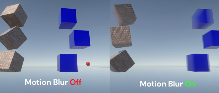
GitHub
A simple implementation of a Per-object motion blur effect for Unity URP (v14+) - GitHub - Estradel/URP-Simple-Per-Object-Motion-Blur: A simple implementation of a Per-object motion blur effect for...
I SUSPECT (without looking, admittedly, so I shouldn't be typing this at all really) that it's all the "other way around".
That attributes struct contains the variable to hold the calculated result of the previous position to pass to the frag shader via interpolation. Calculated in the vert() function.
So the question isn't "how did Unity populate it" but "How do I calc it to populate that variable"? I think they're using the current position and grabbing the motion vector and calcing the previous position from that. In the vert stage. So setting camera motion vectors to on gives you that motion vector and its associated magnitude. That direction and magnitude gives you the previous position.
As to ECS jitters, I get jitters just thinking about it. 😉 IDK
Oh that makes sense. Then they don't have to store previous values. They just have some way of getting the current motion vector of moving objects... which is a bit of a black box to me. I'll have to take one more look at their code for the motion vector pass. If I can create my own custom pass for 3d motion vectors it'll be swell. But there is that ecs eccentricity.
Shader error in 'Hidden/Volumetrics/ApplyToOpaque': invalid subscript 'uv' at line 74 (on d3d11)
https://pastebin.com/XLJ8AQ76
Pastebin
Pastebin.com is the number one paste tool since 2002. Pastebin is a website where you can store text online for a set period of time.
I'm using URP
And I updated my unity version from 2022.1.14f1 to 2022.3.0f1
And now I'm getting this error and the screen is totally purple, but not the UI
Compute threads are the independent simulataneous processing queues, and when one thread writes memory there is no guarantee that other threads will see value changes in that memory. So, to guarantee that all memory write opearations are completed at given shader point, GroupMemoryBarrierWithGroupSync/AllMemoryBarrierWithGroupSync functions are introduced.
Any idea why the shader preview is appearing as black? Also the light looks like its softer than it should be... I'm using Shader Graph in Unity 2022.2.1f1 Built-In

It's an unlit shader, but also occurs on a lit shader
Because in relatime 3D, all meshes are made of triangles, when exporting from blender the mesh get's triangulated and that's what it shows.
To have a similar wireframe as the one you see the easiest choice would be to bake the UV lines in the texture of the mesh.
what about a shader that uses quads instead?
There is no such thing
?

The page mentions that it removes diagonal edges.
I'm not 100% sure about how they do it, maybe just some filtering (you can still see some triangles), but really, shaders work with triangles and that's all
No sure. At the center of your mesh you have a n-gon that might be tricky
Like I said, baking the UV lines in a texture might be enough

there is a small mistake in this shader that I am having difficulty tracking where its occurring.
Everything works except that its 'default' state is a range of 1 to greater than 1, where as I want its default state to be 0.
Every attempt to compress that default to 0 from 1 hasnt worked


Ive tried subtracting 1 at various stages but so far nothing i've done has made the mesh be 0,0,0 instead of 1,1,1 at its default
where do I subtract 1 to make the meshes be 0,0,0 at the end? Do I even subtract?
hm removing the add seems to do it but that might be just because its a sphere 🤔
gotta test other meshes
Yeah, you're adding ontop of the original vertex positions so makes sense there's an initial size. Though if you want this to scale other meshes you should just Multiply against the Position rather than using the Normal Vectors.
Hm thats a good point, I am not sure if my intent is for the mesh to 'swell' along vertex normals vs. multiply the entire thing larger 🤔 I will get better test meshes in than the temp sphere
Yo cyan, sorry to bother you but I was wondering if you could help me out a bit with the shader I've been converting from hlsl to Shadergraph
I've been stuck on it for a while since the shader on hlsl does display properly but not the one from shadergraph, as it has no display at all 
I replied to my original message of it, but if you need more info I'll gladly provide it
It looks "softer" here because the project is using Gamma colour space rather than Linear. Should be able to change it under the Project Settings somewhere (I think under Player).
As for the Main Preview being black, not sure. Try dragging to rotate it, maybe the white side is facing away? Otherwise it's bugged - could try a different Unity version. Otherwise just save and preview in Scene/Game views, that's where it's important anyway.
There is no point filter? Is it possible to define a custom filter?

"Nearest-Neighbor"
But it don't feel sharp enough. Its doing this which shouldn't happen

Actually there is. Quad patches for tesselation shader input. But this is whole different story and skill level 🙂
Switching to Linear did fix the softness, but the actual lighting is still broken. When I add a smoothstep for instance, instead of the result matching it, it changes the color of the entire object. This persists outside of the shader editor in the scene / game view.


What are we looking at? Is it geometry boundary or a texture?
Also make sure AA is disabled on the camera
its a shadow on the groound
Yeah, a bit different also as most of the time wireframe shaders use the geometry stage to do barycentric coordinates calculations
Try disabling soft shadows and increase shadow resolution (or increase their effective resolution with cascades)
if you want to shrink the object to nothingness use multiply for values smaller than 1 and add normal when larger than one
Of course this is far from direct equivalence between this methods.
This shader is applied to individual spheres, right ?
You could as well use a lerp on the vertex position :
Lerp from vertex position to 0,0,0 based on the distance to the object.
its only a sphere in testing, ideally it would be other meshes
Not sure what you mean by lerp, my understanding is transforming vertex positions should be done in shader rather than CPU because thats more performant 
Lerp like lerp node
ok so i need some sanity checks
This would be even more valuable as other meshes with complex normal would react very differently than spheres
OH linear interpolate, for some reason my brain was reading that as a for loop. I see what you mean now
Hey guys sorry to inturrupt but im making a tower fesne game and im tringto make a radius effect kinda like in Ballons tower dense when you place a money you can see its range.I was wondering howcould i achive an outline around a towers border in unity?Woud this be considered shaders?so see that irclecollider how could i highlight that or put a outline over it in game so i can see he towers range?this isalso unity 2d btw

Looks like you're in a situation that calls for vector graphics which involves procedural geometric modelling. Personally, I would use acegikmo's Shapes asset for that sort of task, especially if I had other hud elements that had to be vectorized but if you only have a few fixed radii then you could get away with sprites that indicate the radius, and not need any fancy geometry creation.
well i lawalys change the radius for the tower once at the start and another one when upgrading
could you link the asset pack?
mycomputer is slow
Scalable circles can be made easily with a shader
The Shapes asset is good but totally overkill
No it's a paid asset. Kind of expensive and if it's just for circles it would be overkill, as spazi said
https://assetstore.unity.com/packages/tools/particles-effects/shapes-173167 it's here if you want to consider it

Use the Shapes tool for your next project. Find this and more particle & effect tools on the Unity Asset Store.
At it's simplest, you could use a quad with a circle texture. OR use something like the default particle texture, with an Alpha Clipping/Cutout shader.
For different sizes, just scale that quad.
A shader in favor of a simple texture is necessary only if it's important to have a hollow or bordered circle with an absolute width edge
I am trying to increase the distance of my shader effect but my brain is failing to grasp when/where to do this. Currently the effect goes from 1 at 0,0,0 to 0 at 1,1,1+, but anywhere I try inserting multiplication on that just screws up the whole effect

the end goal I want is a float value that increases the distance over which the effect lerps from 0 to 1
I havent gotten to the other suggestions people had from before yet, I am still trying to get this version working before I completely re-write it
Should be before the Saturate i think
I tried that and it just broke everything. Additionally I tried using its position instead of vertex normal like someone suggested but that also broke everything

I cant describe the way its broken so here is a gif of what I mean by it broke everything
oh I was using world postions instead of object positions, thats on me since the vertex normal was in object
the problem occuring is that this does the opposite of what I want
- I have to saturate it or else the meshes turn inside out
- I have to one minus it or else the effect is 0 at 000 instead of 1 at 000
- but I cant multiply it because all that does is make it smaller range instead of larger

You probably want a Divide instead of a Multiply here
as in a 'distance' of 2 means the range becomes 0.5 to 0
hmm I guess that makes sense since I want to do the opposite 🤔 , let me try that
I always avoid using divides where I can since mult by 0 cant break like divide can
(not that this value should ever be 0)
made it a slider to prevent accidental divide by 0s

I mean, you can keep using multiply but then you'd need to use values like 0.5 rather than 2. It's probably easier to keep it in terms of units rather than 1/units
Yeah that worked, thanks again Cyan 👍
Yeah you're right
Trying to do a basic shader, learning hsls. First image is how a single tile in an isometric tilemap looks like with the Sprites-Default material. Second image is how it looks with my material. This happens with a simple shader unity creates on Create/Shader/Unlit Shader. I was following the docs on https://docs.unity3d.com/2021.3/Documentation/Manual/SL-VertexFragmentShaderExamples.html


The Unlit Shader template is an Opaque shader so isn't really designed for sprites, which are typically Transparent and need to use the alpha channel of the texture. Could instead use the Sprites-Default.shader and UnitySprites as a basis - https://github.com/TwoTailsGames/Unity-Built-in-Shaders/blob/master/DefaultResourcesExtra/Sprites-Default.shader
https://github.com/TwoTailsGames/Unity-Built-in-Shaders/blob/master/CGIncludes/UnitySprites.cginc
Hi, maybe this is a dumb question but even ChatGPT says this should be correct.
I'm trying to make a shader that reveals a gameobject only up to a specific height (usage in a 3d printer scene). I get the following error:
undeclared identifier '_Height'
In my opinion _Height is defined, what am I missing?
Shader "Custom/printerRevealShader"
{
Properties
{
_Height ("Height", Range(0, 1)) = 0.5
}
SubShader
{
Tags { "RenderType" = "Opaque" }
CGPROGRAM
#pragma surface surf Lambert
struct Input
{
float2 uv_MainTex;
float _Height;
};
void vert(inout appdata_full v)
{
// no changes required
}
void surf(Input IN, inout SurfaceOutput o)
{
o.Albedo = 1;
o.Alpha = 1;
float height = _Height * IN.vertex.y;
o.Position.y += height;
o.Normal = normalize(UnityObjectToWorldNormal(IN.normal));
o.Pos = UnityObjectToClipPos(v.vertex);
}
ENDCG
}
FallBack "Diffuse"
}
What am I doing wrong?
What am I doing wrong
Using chatgpt, at least
It's useful for learning new stuff, it helped me a lot, so I thought it could also help me learning how to make sharders
at least for fixing my shitty shader
Chatgpt can teach you some fundamentals but it will not fix your shitty shader, atleast the version 3.5 is not capable of doing so
And sometimes ChatGPT will make up solutions that contain things that don't even exist!
For the most part, I use it as a sort of search engine. The variant I use is called Phind, because it includes sources, and I often wind up following up on those sources.
Hey all, I'm trying to setup up my sprite with lighting. I went and created a normal map for my sprite, and I installed the universal pipeline, set it in project settings, created a material with the nromal map using the sprite-lit-default sahder. I then applied that to my sprite and.. well nothing. Oh I also created a light.
But ChatGPT 3.5 absolutely cannot be trusted to create a whole working shader from scratch because it jigsaws code together that could be for URP, HDRP and even BIRP, and doesn't take into account whether that shader needs to work for Single-Pass Instancing / XR, or whether that shader is a full-screen image effect or meant to be applied to a mesh.
lol speaking of, I tried to have GPT 4 create an outline shader... it didn't work very well
Could you provide a screen shot that could better help us understand the nature of the "nothing?" Did it wind up completely transparent? Did it turn magenta? Is there a sprite shader but it doesn't react to lighting?
The sprite didn't change at all
no weird artifacting or anything

tried restarting since I just installed URP, that didn't help
oh normal lights odn't work
yeah... I remember something about 2D lights
I've never used them myself, but this came to mind
hope it works for you
they must be part of a package I don't have
it kind of indicates it's part of URP though
OH btw I linked an OLD version of the manual (link updated)
ahh, so I can add the light 2d component
but it throws a warning I don't have something set
that must be why
yeah your render pipeline asset needs some setup stuff as well. The manual page talks about some prep steps.
Yeah it's not selectable so I must be missing something there
got it, it was the setup stuff I needed, thanks 😉

not really viable for what I'm doing, but I wanted to see how it looked. I created a normal map from a height map.... that I made by hand.
I'm not sure you got an answer?
Anyway add "float _Height;" somewhere in the area between functions at global scope.
The Properties section is used by unity and the inspector, but it doesn't actually declare it to the code. You have to do both.
I SUSPECT without looking admittedly so
I've got a shader that is mostly working but I can't seem to get normal maps to work

I've verified the texture is being read correctly by applying it to the albedo, and ive double checked that it's setup with the correct texture type

I've also tried using UniversalFragmentBlinnPhong, both don't appear to be influenced by the normalTS surface data property at all. Am I missing something?
ugh, looking at the source, it appears i misread it and it expects the normal in the lighting info and not the surface data, guess the surface data normal is just not used :S
Woo, its working, though i still gotta fix the smoothness of the mesh itself

Ohh okayy, thx

Assuming Unity 2021.2+ "Category" should be on the same + button/dropdown that you use to create the properties
Should be able to drag them. There's no shortcut that I'm aware of
Anyone got a suggestion on how to make a magic cloud type of effect? Something with a little bit of movement, a little bit of twirling
hello everyone, i'm wondering if it is even possible to create realistic blood splatter decals (the ones on the ground and walls) only using shader graph? if yes, then how, because as i've been experimenting with various noises, it still doesn't look quite realistic enough.
premade textures I guess
so the answer is no?
If there is a way, then it almost certainly requires multiple layers of noise. One for the main shape, and additional layers for detail.
it is possible purely by shader graph, but it is not advised, it's expensive to calculate noise and you should ideally use a lookup texture everywhere you can without noticable quality change
also, if you want further advice, post a pic of what you have, one of what you want, and another one for the background you are planning to use it against
otherwise there's so many looks blood can take on, could be dried, slimy, wet, smeared, droopy etc, there isn't just one "realistic" look
also, which rendering pipeline
new version built-in, which as far as i'm aware supports both shaderlab and shader graph, since using PCSS shadows made for unity 2019 built-in version causes no problems, and so does my custom shader graphs
1, 2, 3 are what i get, basically miles away from being even a bit realistic, 4, 5, 6 are what feels realistic to me, though they all are a bit different so keep that in mind (also for the mods these are just assets from unity)


yeah, i think i should just stick to textures, or perhaps it's possible to mix a bit of textures and the noise 😄
okay, so the circular cutoff is just completely wrong, you should treat the noises and the circular distance as height, and add /subtract them together
so maybe 1 low freq noise - 1 slightly higher freq noise, - 1 distance from the center * distance falloff ,
you also need to have a normal map for it, theres a height to normal node. I'd suggest using a gradient to control the height, as it's easier to replicate surface tension at the edges with that
the shinyness and environtment reflection is completely missing, grab a free skybox and bake the lighting for the scene along with a reflection probe
then add to the specular and metallic values with some random noise aswell
this doesn't have to be as accurate as the shape of the blood
the color is also way off, the blood on the bottom is waaay darker in the middle
thanks, but since i'm a beginner i'll need some things cleared up: i really don't understand how to do that falloff that you mentioned, i found the height to normal node, so what do i put in the "in" node?
height is just a float value you calculate
so, grab 2 noises and subtract one from the other
ideally the one you subtract is higher in frequency
after that, grab the distance you have calculated for the circular falloff, and add it to the combined noise we just calculated
btw to get a more similar color, shift the color to the darker side and a bit towards full red or blue, it's just too orange
yup, it doesn't help that i'm using this falloff thing which is brighter in the middle
