#archived-shaders
1 messages · Page 47 of 1
thank you!
no it's more like Vector2

Yep, the shader is incompatible with your render pipeline, or has errors @boreal berry
is there a way to change my render pipeline without happening a lot of bad stuff?
Having some strange issues with normal maps on my surface shader
to debug some issues im currently just using a color as the normal so i can get the entire surface in a single direction

i can only get the normals to point straight in the Z direction if R and G and 0
the ordinary default value for an empty normal map is 0.5, 0.5, 1, 1
but this makes it point bottom left


Hey I was wondering if I could add multiple materials on one object
That fade away shader material I did earlier I want that to still happen but I want each objects to have texture of their own
More like they have their regular materials but with a different material that controls the alpha with step node
I could actually just make the one fade shader do everything come to think of it. Add texture and tiling that can be changed for all of them
I think this is the place to put this
so I'm putting the texture maps onto a material, one of the exported maps is a mask map
This isn't on the material, after doing some digging I found one person who made it show up by having the material selected, going edit > render pipeline > upgrade to high definition, but that option isn't there for me either
does anyone know any other ways to make this appear?
Materials are basically interfaces for shaders and their property. If a material doesn't have a certain property, it's using a wrong shader.
Also, shaders from outside unity don't always map to unity shaders 1 to 1.
Unless you recreate that shader in unity.
The most common way is with a custom shader or a postprocessing effect(also involves a custom shader).
Not necessarily. It depends on the specific shader that you use.
It should still have normals.
Hard to say anything specific without the details of your implementation.
Did you try using the opposite of the normal direction?
-normalDirection
Because that should push the outlines into the mesh. Although, I'm not entirely sure about the rest of your implementation, so it's just a hypothesis.
It's better to use edge detection to draw the outline if you want the outline to be inside the mesh.
would it be possible to export a shader texture into multiple pngs to resemble a flipbook like animation?
Does anyone know if there's a way to cut a hole in a mesh using another mesh?
I know there's culling masks, but that acts like a magic lense and causes problems at certain angles.
Usually you need to change a lot of materials. It's easier to change the materials on the asset instead
a shader only has one output target
I highly recommend stencil buffers as well
It looks like stencil buffers are the exact same thing as the mask I'm referring to. Let's envision the desired result:
I have a plane and an invisible sphere. I can move my sphere into any part of the plane and I will see a circular hole in said plane. All angles its viewed at will result in a circular hole.
However the buffer will make it so anything seen through the sphere is gone even if the sphere isn't meeting the plane. Looking at the sphere at some angles will result in a long hole.
fixed4 color : COLOR;
https://docs.unity3d.com/Manual/built-in-shader-examples-vertex-data.html

Maybe the vertex color didn't export properly ?
What format are you using ?
One way to check would be to import the mesh back in a brand new file in you modeling tool, and check if the colors are still there.
Maybe you've missed a checkbox when exporting ?
But this is more a question for #🔀┃art-asset-workflow I guess 🙂
Does anyone know if it is possible to pass a array of positions, instead of matrices when using gpu instancing (fixed scale/rotation). Cant find any examples online, thanks a lot
https://alexanderameye.github.io/notes/rendering-outlines/
https://bgolus.medium.com/the-quest-for-very-wide-outlines-ba82ed442cd9
https://www.youtube.com/watch?v=5EuYKEvugLU

Different techniques for rendering outline effects.


In the realm of image based edge detection, aesthetically pleasing edges are hard to come by. But, what if we could get stylized edge lines by just blurring our image twice?
Download my GShade shader pack!
https://github.com/GarrettGunnell/AcerolaFX/wiki
Patreon: https://www.patreon.com/acerola_t
Twitter: https://twitter.com/Acerola_t
Twitch: ...
That last one is a really interesting full-screen stylized technique.
But from your question I cannot tell if you're after an outline art style or an outline effect on one object to "highlight" it.
Hi, is it possible to make a node composed of other nodes ?
For example, I've would like to regroup this pack of node in one node named "GetMinMaxValues"

select and "convert to sub-graph"
Fantastic, ty
yes the dog is pretty fucking cool
hello guys, I need help with ShaderGraph.
I`m beginner in unity especially in ShaderGraph and I want to know why Alpha in Sample Gradient is not has Alpha like Gradient
||sorry for bad english||


It has alpha, it's just not displayed on the thumbnail


Thank you very much! it works now.
I'm looking to learn more about shaders and the book The Unity Shader Bible has been highly recommended, but I'm curious if anyone has read it and thinks it might be quickly outdated? Considering it sounds like it covers shadergraph, render pipelines, and other unity specific components, I'm concerned about it's validity as I start working through it, especially given the time frame that it was released, during a lot of major changes with pipelines in Unity. Is it still worth it for the general information?
if you are looking for books for shaders and rendering I can recommend you gpu gems, zen and pro, they are by far the best resource for learning real world rendering techniques. They are not specific to unity tho.
Those all look pretty advanced. Looking through them they seem to expect that you have a pretty decent understanding of the basics of graphics api's. I'm looking for something fit for a beginner.
The basic concepts are the same whether you use shader graph or HLSL, I would recommend the unity shader bible for that reason. Also catlikecoding and https://www.ronja-tutorials.com
hm, I do not really know any books like that, but I can always recommend catlikecoding, its a very good recourse
Yea I have just started looking into that website as well! Sounds like I should continue there and I may consider picking up the unity shader bible as well just to have something to go over for reviewing the general information. Thank you both!
While books like that do collect information into one place, I will mention that most of the content is probably similar to free tutorials by other creators. I've got a list of some resources/tutorials/sites here which could be useful : https://www.cyanilux.com/resources/ (as well as my own tutorials on the contents page)
Oh wow this is a great list of resources! I do use a lot of the free stuff that are online as well, but I find that for subjects like this I tend to learn best from books as they tend to cover the topic as a whole in one place, vs tutorials that tend to be split up or cover just one very specific way of doing something. Books tend to usually get into the how something works or the why we do this, vs just showing how to do something.
thats a great list allready, but, if you are including shaderbits raymarching, not including scratchpixel is a capital offense 
hey im looking for good resources to learn more about vertex animation textures, could someone please provide me any ressources?
https://github.com/keijiro/HdrpVatExample
Probably stuff like this and other VAT repos

GitHub
VAT (Vertex Animation Texture) with Unity Shader Graph and Visual Effect Graph - GitHub - keijiro/HdrpVatExample: VAT (Vertex Animation Texture) with Unity Shader Graph and Visual Effect Graph
is it possible to make a shadergraph that is normal map only... like it blends with the surface behind it, without using deferred rendering?
Should be possible in URP with the Decal Renderer Feature (DBuffer mode) & Decal Shader Graph.
So, are the texture sampling methods themselves (bilinear, nearest neighbor, etc) hardcoded into the render pipeline, or handled in each shader which uses texture sampling?
Or something else
I would guess it'd be pretty hard to implement new sampling methods into texture importing itself
Afaik the texture filtering is handled in shader by gpu hardware itself rather than Unity.
For custom filtering you can do multiple point-filtered texture samples with offsets and then combine those with some logic, I think that's what Remy is probably suggesting. But that won't be as cheap of course.
idk if this is a shader question but
idk why this happens or how to fix it
i suppose it is some crazy bloom
Looks like negative/NaN values being output by the shader. Probably need a saturate function/node somewhere.
ty i'll look for that : D
i figured it out
it was post prossecing
i had accidentally duplicated my global volume
i'm targeting oculus quest so i feel like the dbuffer stuff might not be a great idea
there's no other way to do it? if not i'ma just re-use the texture map of the surface underneath the "decal" for the diffuse channel of the decals that go on top of it
in forward rendering the object is shaded in it's own fragment pass, so if you were to add a normal map on top you still can't know how to alter the already shaded surface
you can go in the route you mentioned tho, should be decent enough
is it possible to adjust properties in the "pass" stage (or earlier?)
I have a serialized variable in a bunch of legacy scripts using "glossiness" and newer hlsl includes that should be using "smoothness", so I'd like to make smoothness hidden in the inspector, but equal to glossiness, which already has values set
if you are asking if you can do something like this in the subshader or pass (not in frag/vert..): float smoothness = glossiness, then no
I figured. Would you happen to have any other suggestions for how I could solve this problem?
Wondering if I should write an editor script to store all references, change the shader, then re-apply, but I'd love to know if there's an easier approach
Hello can someone help me understand why this shader is not working? my main preview seems to be blank. I downloaded the file from a tutorial video but them main preview that I see is different for some reason

is there a method to debug the exact value of a float? If I know the float is a single value for every fragment
There is a value that I -think- I know the value of, but thats only guesswork 
that question is xy of course
what im -really- trying to do is make my shader dynamically compensate for these values changing

Mathematically, how can i warp a texture to fit the normal map applied to a flat plane

like consider the following normal map
the texture being applied to it would need to warp so that the image would warp away from the camera around the edges
float2 morph = o.Normal.rg;
float2 offset = _WorldSpaceCameraPos.xy * _ReflScroll * _ReflTex_TexelSize.xy;

reflUV = reflUV / morph + offset;

fixed4 refl = tex2D(_ReflTex, reflUV) * _ReflMap;
o.Albedo += refl;
this is what im doing right now, but it's not correct

hm I have values but now my problem has turned into a math problem and I am not skilled at math

if XYZ are those values, then W is that value, but how do I use this information to determine the formula that automatically calculates W for me from XYZ
is there some brute force machine method that can solve this just by giving it enough samples of data until only one formula can possilbly fit?
Where can I even ask a math question like this to get a sollution?
chatgpt unironically
hi ,
I wanna ask about something that is probably related to shaders but I'm not sure.
if i'm building an FPS game and I wanted to add a healthbar on the screen (I think its called GUI but, not sure.), what is the right approach to it?
do we make a gameobject stuck to the camera all the time and make child transparent images for health bar and other details ?
or is there is a better approach that Im not aware of ?
unity has a UI system
use that
yes i know , the canvas ? I thought there might be a more professional approach from the camera component itself
yep the canvas

Let's create a simple health bar using the Unity UI-system!
Get up to 91% OFF yearly Hostinger Plans: https://hostinger.com/brackeys/
Code: "BRACKEYS"
● Brackeys Game Jam: https://itch.io/jam/brackeys-3
● Project Files: https://github.com/Brackeys/Health-Bar
···················································································...
oof we are in the shader channel
oh well
but any further UI questions ask in the UI channels but there
Thanks a lot ❤️
Hi I’m using Blit to create post processing effects with URP Shader Graph, but it seems to only have access to the screen texture, how can I mask specific objects in Blit Shader Graph, I’m thinking I need to use stencils or layer mask? But I don’t know how I would access that in shader graph
I’m hoping the new Fullscreen Shader Graph Unity added will have some useful masking features
So if anyone can shed some light on that let me know
on 2022.2 now with the built in fullscreen shader
i see the fullscreen shader graph has 'enable stencil' in it and can set values, but i can't find where you would set this on other objects in unity?

seems to be missing in normal material shader graph:

and objects don't have a setting for it:

ideally i'd want to mask out stencil values in the post process based on what stencil values are set for objects, not set a stencil value for the post process itself, seems kinda backwards
if you're using URP and want to apply a shader only to specific objects i suggest you look into the Render Objects render feature https://www.youtube.com/watch?v=szsWx9IQVDI

Let's learn how to render characters behind other objects using Scriptable Render Passes!
This video is sponsored by Unity
● Download Project: https://ole.unity.com/occlusiondemo
● More on Lightweight: https://ole.unity.com/lightweight
····················································································
♥ Subscribe: http://b...
can anyone help me with a vertex color issue?
is it possible to change the way vertex colors are interpolated when used by the fragment shader?
heres what i mean:

trying to avoid the muddy blending and get a flat-shaded look while still using vertex colors
shader graph or hlsl, it doesnt matter
I think the name of this is regression
I have never tried myself, but in theory you can use hlsl interpolation modifiers to you v2f struct members : https://learn.microsoft.com/en-us/windows/win32/direct3dhlsl/dx-graphics-hlsl-struct
Like this in your case : nointerpolation float4 color : COLOR;
Struct Type
not sure what you mean by that
Hi, is there a way to do something like clip(-1) and clip(1) in URP shaders ?
I have entry door, with two corridor on each sides and I want to cut them with two clliping planes
Anyone know if there's a way to use stencil buffers in a localized area? I want to only affect a small portion of a model to achieve a stylized mouth effect. This is in opposed to regular stencil buffers that will affect anything seen through it.
I've tried using stencil buffers so I know how to construct the mouth part. I just need to know how to basically cut into a model that intersects (preferably the paired materials)
[doodle for stylized mouth]

I think the nointerpolation uses the value from the first vertex for each fragment or something similiar so the whole triangle gets the same color, not exactly what they drew but could give the result they want
That's the closest solution I had.
Other is to implement some sort of custom interpolation, but that would require to greatly raise the number of interpolator data (something like weights per vertex and 3 colors)
and why would you not like to have two passes
Yeah, with barycentric coordinates it should be possible but bit tricky
Interesting. That looks new to me.
As you note, there's two "sides" to stencils. The setting (1) and the testing (2).
You want the setting to happen on the objects in question.
The testing happens on the full-screen post processing pass.
What ends up happening is that the frag shader will only be called for those pixels that pass the stencil test.
Now, the question becomes (and you asked it) whether or not SG supports setting the stencils on regular objects or not, or if you can use custom node to inject the needed shaderlab code for the stencil setting. I don't know that answer, but if SG isn't giving you the options to set the stencil values on "regular materials" that's about your only hope: Code injection with custom function. Or you can generate a graph, and then turn around and manually edit the code afterwards. Ugh.
no, not always, there is the overhead of setup up things again but thats negligible and you will still have to do the same work no matter where you put it
Is there a way to have tessellation in ShaderGraph URP?
Looking at the net it seems like they added it for HDRP, but I can't find it in the other pipeline.
Looks like you want the resulting color to be one of 3 colors (whichever channel is the max value of the interpolated pixel color). Conditional logic. Could be any 3 colors BTW. Or just return a 1 in whatever channel is the max value. Watch for equalities.
No
Are you remapping the vertex color to the [-1;1] range ?
Also, you might need to do a Gamma -> Linear conversion of the color beforehand
its best to do it inside a compute shader
Normal unpack might do a Z recalculation, as it is made for 2D normal map textures. If you store a Z value in the vertex color, I would recommend to do a simple normal = normal*2 - 1 calculation .
As for the colorspace, I would not trust any export setting, and would try in the shader anyway, I'm never sure how Unity / shadergraph handles the colorspace for vertex colors
You'd want to look into transformation matrices if you don't understand those. You don't necessarily need to understand the maths behind them, but how to use them is pretty important.
For tangent space in particular, this looks like it goes through some explainations. https://catlikecoding.com/unity/tutorials/rendering/part-6/
In short, converting to & from tangent space uses the tangent and normal vectors stored in the mesh (and a binormal/bitangent, which is a cross product between the two). That article uses bump/normal mapping as an example :
float3 binormal = cross(i.normal, i.tangent.xyz) * i.tangent.w;
i.normal = normalize(
    tangentSpaceNormal.x * i.tangent +
    tangentSpaceNormal.y * i.normal +
    tangentSpaceNormal.z * binormal
);
(also common to construct a matrix instead)
float3x3 matrix = float3x3(i.tangent.xyz, binormal, i.normal);
i.normal = mul(tangentSpaceNormal.xyz, matrix);
It's more common to go from tangent->world space as that's the space for dealing with lighting calculations. For tangent->object it's probably the same thing, you'd just wouldn't convert the tangent & normal to world first.
Unity's shader includes will also provide functions for converting between spaces. e.g. For SRPs : https://github.com/Unity-Technologies/Graphics/blob/master/Packages/com.unity.render-pipelines.core/ShaderLibrary/SpaceTransforms.hlsl
So, for some reason rotating my object is changing how the material looks, anyone know why?
having trouble finding results by googling
moving the camera is also changing it
Is it a custom shader? Can you provide screenshots?
this is how it looks when i enter the player view

these are materials made in substance painter
i'm trying to posterize/step post process my scene

problem is the posterize node doesn't use the original colors, it just kinda makes it's own:

how would i get it to posterize like this and respect the original colors?

Unpack normal already does a * 2 - 1 conversion
So your doing it twice
Oh my bad, on discord mobile it crunches the codw together
You are adding a tangent space normal to an object space (or world space) vector, that being the vertex
This worked before because the normals on the object are in basically the same "space" as the verticies which is object space
And?
Same results?
Ah
I'd been working on a grass shader to make it move in the wind but when I'm testing it on a plane in the scene, the plane turns invisible. I have checked all my nodes are set to object space and I have enabled double sided normals for the graph. anyone know what's up?


You'll want to check your spaces & maths. You're using Object space for the Position node, but then transform from World to Object. Either remove the transform or use World space on the Position node.
You also subtract the worldspace position of the camera? If that's because you're working in HDRP (which has camera-relative world space), you can use Absolute World space instead. For other pipelines, you probably don't want the grass moving with the camera so would remove that subtract.
still has the same issue from trying those
https://www.youtube.com/watch?v=R9MoyEOdmeA
^ i followed this dudes tutorial and it's throwing me this error the viewport and game tab is blank i'm losing my sanity over this shit please help
i'm tryna make a custom post processing effect with shader graph
dumb question: I'm struggling with setting up keywords to toggle a block of code in an included .hlsl file.
In the shader I am doing
Properties{
[Toggle(_KEYWORD_TEST] _KeywordTest("keyword test", Float) = 1

Pass{
#pragma multi_compile_fragment _KEYWORD_TEST

#include "SimpleLitInput.hlsl"
#include "UseInput.hlsl"
inline void InitializeInput(){
#ifdef _KEYWORD_TEST
  (test thing that doesn't happen)
#endif
initialize input gets called in the fragment shader of UseInput
you don't use
"#pragma multi_compile_fragment _KEYWORD_TEST"
instead
you use
#pragma shader_feature_local _KEYWORD_TEST
@blissful marlin
works perfectly tyvm
hi everyone i have a question i want to design game like this photo
but i dont know which type of shader i have to use for this graphs

am i dumb or is this the wrong description for uvs:

pretty sure they meant the uv vector
poor description imo
I imagine a lot of the pages were copied and edited (i.e. from Sample Cubemap where that does have a Normal field). Obviously they forgot to change that part. But it only says that in old versions of the docs, v8+ onwards says "UV coordinates". https://docs.unity3d.com/Packages/com.unity.shadergraph@12.1/manual/Sample-Texture-2D-Node.html
It's quite annoying that google tends to list old v6.9 links first though
yeah i often get some times unity 5 docs when searching for regular monobehaviour stuff too lol
Just to be clear, shader_feature works better if you're toggling on material but strips unused shader variants from the build. If you need to toggle at runtime from C#, you do need to use multi_compile. From the sounds of it you don't need that, but still good to know.
Note that the syntax for multi_compile requires at least two keywords (for the off and on states). Can at least use #pragma multi_compile_fragment _ _KEYWORD_TEST with that extra _ to specify the keyword isn't needed.
For some reason the shader_feature syntax is different and allows for one keyword. 🫤 With that it automatically handles the off state, hence why it fixes this.
More info in docs : https://docs.unity3d.com/Manual/SL-MultipleProgramVariants.html
Hey there, I'm having an actually strange problem where my shader becomes invisible when I run the game in the editor. I have only one script that changes one value which doesn't affect the colour of the shader, it simply moves the normal maps. Left is the normal one, right is when I run the game.


I'm distorting a mesh using vertex position offset, how can I get the correct fresnel effect for the new mesh shape? I feel like the fresnel looks the same when the mesh is not distorted. Any idea?


You would need to calculate the new normals as well as vertex positions. I've got a couple methods listed here : https://www.cyanilux.com/tutorials/vertex-displacement/#recalculating-normals
Looks like it's a water shader. If it's using the Scene Depth node make sure the Depth Texture is enabled on the URP Asset. Same goes for Scene Color & Opaque Texture.
Thanks @regal stag that's exactly what I was looking for!
you'd probably want some vertical fog for the base tiles, and some screen depth based foam for the water, but I'm assuming the picture is just drawn since the shadows are very random. Other than that the standard urp lit shader may work, shadows may not look exactly like in the pic. You may also need a LUT for the lighting to have it stylized like that, but thats more complex
how come Unity compute shaders compile just fine when you write to global variables but something simple like this fails to compile here? https://godbolt.org/z/r7cvhcWGf
// The entry point and target profile are needed to compile this example:
// -T ps_6_6 -E PSMain
RWTexture2D<float4> Result;
int forA;
int testMethod()
{
int forB;
int variableA;
for (forA = 0; forA < 10; forA++)
{
for (forB = 0; forB < 10; forB++)
{
variableA = forB;
if (variableA == 5)
...
I don't know about compute shaders in particular but variables that are defined in the global scope have some default modifiers, like extern which specifies it is an external input (set by Unity). Apparently also const meaning it can't be edited by the shader and the declaration must set it. See : https://learn.microsoft.com/en-us/windows/win32/direct3dhlsl/dx-graphics-hlsl-variable-syntax
Adding the static modifier seems to make it compile on that site, but that's meant to only be initialised once so not sure the ++ will work?
the thing that weirds me out is that in unity it seems to not matter at all whether a variable is global or not, or static or not. i can still write to it just fine in the script and there's no issue.
except in some edge cases
where it just breaks
man i wish my code wasn't so big so i could post something because i'm having huge issues with for loops still which is why i am grasping at straws
for example i wrote that code to recreate the for loop bug i was running into
and at first as I was running that it would return 0 instead of 1 no matter what
which confirmed my bug from my main code
but then my computer bluescreened and when i ran it again it worked and i could no longer recreate the bug
but in my main script i keep having weird things happening when you have a nested for loop where you assign to a variable with a global scope or at the top level of the method, and then use it outside of the for loop after it exits or you break, where it would basically use undefined data or reset it to 0
If the loop is branching there could be some weirdness with that if pixels aren't taking the same branch
Could try specifying [unroll] before the loops if the count is known, but then exiting early probably doesn't give the same perf benefit
yeah i've tried that but only one loop is unrollable and it just makes it run worse. i've tried setting all the variables as globals, global statics, local variables but nothing seems to really solve it or even change how it acts at all. welp, i'll keep digging i guess, might still be something else.
I downloaded URP but I don't have it as an option my graphic settings, how do I fix this?

Check the pinned links in the #archived-urp channel. The documentation will go through the setup
I just ruined my entire project by converting into URP
is it reversable?
suddenly the trees are black and my character is pink

Not automatically afaik. Typically you should backup before doing changes like this so you can rollback. Would need to remove the pipeline asset from the project settings and switch the shaders on any materials back to what they were.
Thank you so much man it worked 🙏
you can just go to material and do alpha clipping and for character pink just go to the char mats and change it to URP/lit
well roll back is an option too tho
oh, I already fixed the problem, just removed URP and changed all materials back to standard
hey in my new unity project (URP-3D Template) i have written a simple shader: Shader "Unlit/SimpleShader"
{
Properties
{
}
SubShader
{
Tags { "RenderType"="Opaque" }
    Pass
    {
        CGPROGRAM
        #pragma vertex vert
        #pragma fragment frag

        #include "UnityCG.cginc"

        struct VertexInput
        {
            float4 vertex : POSITION;
            float3 normal : NORMAL;
            float2 uv0 : TEXCOORD0;
        };

        struct VertexOutput
        {
            float4 vertex : SV_POSITION;
            float2 uv0 : TEXCOORD0;
            float3 normal : TEXCOORD1;
        };

        //sampler2D _MainTex;
        //float4 _MainTex_ST;

        VertexOutput vert (VertexInput v)
        {
            VertexOutput o;
            o.uv0 = v.uv0;
            o.normal = v.normal;
            o.vertex = UnityObjectToClipPos(v.vertex);
            return o;
        }

        fixed4 frag (VertexOutput o) : SV_Target
        {
            float2 uv = o.uv0;
            float3 normal = o.normal;
            return float4(normal, 0);
        }
        ENDCG
    }
}
}
The preview is rendered but not actual gameObject in my scene can someone help me?
Newer versions of URP have "Depth Priming" enabled on the Universal Renderer.
The shader needs to have a DepthOnly pass (and DepthNormals if using SSAO as well) to be able to prime the depth buffer correctly. e.g. https://github.com/Cyanilux/URP_ShaderCodeTemplates/blob/main/URP_Unlit%2BTemplate.shader
Could instead disable the depth priming, which will make the object visible, but it still may not appear in the Depth Texture / Scene Depth node.
The alternative is using a Shader Graph, which will generate the passes required by URP.
oh god ... but thanks for the info
So if i wanted to benefit from depth priming (less gpu work as i understand) do i have to use hlsl?
No, shader graphs would automatically support it. But for shader code, you need the DepthOnly/DepthNormals passes.
Ok if i use shader code then i would have to use hlsl and not cg like in my example or are hlsl and cg compatible with each other
123
<Compilation failed>

# For more information see the output window
DXC 1.7.2207 - 1228ms
<source>:2385:36: warning: implicit truncation of vector type [-Wconversion]
    mapDepth = shadowDepthMap.Load(int3(shadowBrickMapPos.xy, 0).xyz).r;
uuh what am i missing here
mapDepth is an int
I'm setting .r from the shadowDepthMap.Load and it returns an int
hlsl and cg are essentially the same thing. But "cgprogram" tags include some additional shader files which are used by the built-in render pipeline. It creates conflicts when including shader libraries from other pipelines, hence we need to use "hlslprogram" instead.
ok thank you
I tried to apply simple lighting with a dot product and a light direction i defined in fragment shader but im getting this weird white lines. I used the shader from @regal stag as a Base because of the depth pass.

Likely need a saturate. This kind of thing happens with negative values + Tonemapping post processing.
I also have lit templates in the same repo btw. https://github.com/Cyanilux/URP_ShaderCodeTemplates
Though I'd still recommend using Shader Graph where possible.
Managed to resolve my issue (i think). From what I can gather, if you use certain variables (in this case float3s and bools) that are too far out of scope when using nested for loops (in this case I have at least 3 loops inside each other) the code will break. i experimented with moving variables in as close as possible within the function and eventually it worked after i moved some bool declarations further into the loops instead of being declared within the function but outside the loop.
my float3s worked as globals but bools can't be global if you're going to set them
(but the float3s didn't work as static globals)
the problem is i am trying to learn shader code because i want to implement a simple way to for baking an animation and then displacing the vertices and with instancing support. I would like to instance those objects and i think that this isnt possible with shadergraph.
I already have some experience in shadergraph and is more applicable for me in most cases.
Unity Toon Shader does that by pushing out the normals i think
One more mesh means 1 extra draw call. Polycount is not a very big deal at this point if you optimize other models well or you are targeting PC and console.
Normal extrude is the most common solution for toon style outlines. In most cases, the performance will be fine.
i just clamped the output value to be between 0 and 1
What are you going to do with that normal?
Do you mean something like spherical normal on the face?
I don't know which 3D modeling software you are using, but most of the software has a feature called "mesh data transform" or "normal". You can create a shape that represents the normal you want and transfer the normal data to another mesh. For example, you can create a sphere and transfer the normal data of that sphere to your character's head.
In that case you need to remake your normal map based on the new mesh.
Do you understand Chinese? I have a very great pdf which teaches you the techniques and tricks to make toon shading look perfect. If not I can share with you some presentations on this topic.
In English
PDF File
https://www.youtube.com/watch?v=egHSE0dpWRw
Here is the presentation in English.

Jack He / miHoYo Technology Co., LTD / Technical Director
Anyone know if objects drawn with DrawMeshInstancedIndirect should be affected by post processing in URP(got crickets in the urp channel)?
Have answered in #archived-urp
Is there something like colorramp in shader graph?

If you just need two colours can use a Lerp node
also this work fine

Sample Gradient is closer to what the ColorRamp provides yes, but be aware that gradient values can't be exposed to the material. (If you need that it's common to use a gradient texture & Sample Texture 2D instead)
I am currently stuck with this shader. In the main preview i also want the black parts edges to become blue but I dont know what I can do

Does anyone here use ProPixelizer enough to help me with an issue?
I'm trying to make a custom version of the shader, using the guide in the ProPixelizer Manuel
but when I switch my copy of the shader code to use my copy of the shadergraph
it throws up these errors

It seems no matter what I do, if I switch
            UsePass "ProPixelizer/Hidden/ProPixelizerBase/UNIVERSAL FORWARD"
            UsePass "ProPixelizer/Hidden/ProPixelizerBase/SHADOWCASTER"
            UsePass "ProPixelizer/Hidden/ProPixelizerBase/DEPTHONLY"
            UsePass "ProPixelizer/Hidden/ProPixelizerBase/DEPTHNORMALS"
with
            UsePass "ProPixelizer/Hidden/ProPixelizerGradientVariant/UNIVERSAL FORWARD"
            UsePass "ProPixelizer/Hidden/ProPixelizerGradientVariant/SHADOWCASTER"
            UsePass "ProPixelizer/Hidden/ProPixelizerGradientVariant/DEPTHONLY"
            UsePass "ProPixelizer/Hidden/ProPixelizerGradientVariant/DEPTHNORMALS"
like it says in the userguide for making variants of the shader, It bricks the shader and results in those errors.
You need THREE points to calc a new surface normal. In the vert stage, you have access to ONE point directly...the current vert.
Now, since you're extruding the vert, maybe you can manually calc two other points on the surface...they don't have to be actual polygon verts, just two other points. If you can calc the other two points, the three points make a plane and you can do a cross product to get the new surface normal. The formula is
float3 newNormal = normalize(cross(p1 - p0, p2 - p0));
(I haven't checked that code)
If it is the shader that modifies the vert locations, that's where you would calc them. It's not too bad if you can do it in the vert() function since that's not done for all pixels (unless you have really small triangles), just the polygon corners. It's the "price" of shader vertex modification.
BUT....
If you can modify the mesh on the CPU and calc them, say, once per minute or something, you can look into that. Depends on what you're doing.
If it is changing every frame it's something that I'd do in the shader.
If it is something that changes the mesh, say after taking a potion, and then it stays that way until something happens...do it on the CPU.
you can also do it in a compute shader will be faster and give's you the control of calling it whenever you want
Hey how can i get mainLight direction and color in my hlsl shader? I couldnt find anything on my own.
_WorldSpaceLightPos0
and for the color its unity_LightColor0 although you will need to include unitys cginc file for lighting
Assuming built-in RP you'd want those ^, but for other pipelines it would be different.
URP has it's own includes and would use GetMainLight(). See Lighting.hlsl & RealtimeLights.hlsl in the ShaderLibrary folder of the URP package. (Or can use the Graphics github but will be more up to date. https://github.com/Unity-Technologies/Graphics/tree/master/Packages/com.unity.render-pipelines.universal/ShaderLibrary)
Could someone please tell me why is my clean texture with transparent background turns into this abomination with a white background, once imported into the shader graph?


I think thats just the preview...

how do i get posterize to use a specific color palette? because the colors it produces by default are awful
Sadly it is not. I connected it to the base color and added the material to the object and it looked just like on the preview
Thank you cyan really appreciate your help!
Posterizing and a palette shader are different techniques, seek out the latter
i think i figured it out
but a new problem:

why doesn't render objects material override work with sprite lit/ sprite unlit materials?
works perfectly fine for default lit/unlit shaders, just not sprite ones
here's what happens when i switch my mat to sprite lit to default lit:
https://gyazo.com/4a2bf16413b7e6b40225ec023504b382

the red sprite in the top left should always be blue, but it won't have it's material overridden when it's using a sprite shader
don't forgor to make the shader transparent or alpha clipped, and plug the alpha into it's proper spot
To work with the sprites, you'd need to change the Queue on the RenderObjects filter.
Sprites are always in the Transparent queue, while the Lit shader has the option to choose between Opaque & Transparent (defaulting to Opaque)
😮
very helpful, thank you!
Hi, guys do you know how to convert builtin custom shader to urp?
by rewritting it in urp, if its shadergraf you can probably just copy the nodes tho
Okay thank you
Oh right. I forgot about alpha clipping. Thanks!
Why does the default HDRP/Lit shader sometimes have a _EmissionMap property and other times not regardless of whether or not there's an emission texture?
that almost worked, but it's kinda just putting the new sprite overtop the old one?
https://gyazo.com/56ed009c1329ecfbfc9145f8c3a778ad

That is how the RenderObjects feature works. It renders objects again with given overrides.
With the Universal Renderer asset, there are Opaque/Transparent Layer Masks at the top of that asset to remove layers from being rendered normally, but if you're using the 2D Renderer I don't think it has that option currently.
ah i see, not sure i'll need the override afterall then, just masking the layer should be good enough
thanks again!
sorry one last thing, how do i get the render objects to respect the depth/ sort order?
https://gyazo.com/fea830f4fb6b1045f3d467b7d7985e70

Not sure you can, afaik it's always before all other objects or after (by using the event field).
But I don't deal with sprites often, I mostly do 3D objects where there's still a depth buffer to test against at least.
dang, almost had it working, just trying to mask out objects from my blit post process
what does the sprite mask output in shader graph do?

doesn't seem to affect any masks in the scene
I believe it's for the 2D lights system. On the lights there's blending modes that interact with the mask
Heya everyone, I've got a quick question about custom bindings! I thought I could get nice custom ports for colors and uv's in my subgraphs, but I only get the string I typed in.

which tbf is also what I see here for example so maybe I'm confusing something

I think displaying a string is just how it works
Can have subgraphs have Color properties? Maybe using that over Vector4 would display as a colour box?
huh I see. I was hoping https://docs.unity3d.com/Packages/com.unity.shadergraph@16.0/manual/Port-Bindings.html meant I can have the nice uv input
curiously subgraphs display colors as vector4s too, but I was after the uv's anyway
If I read your whole article I would've seen the branch on input connection, that works just as well! 😁
i am trying to make a transparent shader, but although it appears transparent, it occasionally blocks out objects with the same material that are behind it, effectively making it opaque rather than transparent. i'm not sure what is wrong
here's my shader code:
How do I apply a shader to a certain material without any 'cull command'? I don't know anything about shaders but someone recommended me this as a fix for an issue I was having
Which issue is that?
these white lines appearing when looking at the planet from behind caused by the clouds


Would you guys happen to know how can I do the following via c#?
float2 pos = vertex.xy;

    float3 worldPos = mul(unity_ObjectToWorld, float4(pos.x, pos.y, 0, 1)).xyz;
    float3 originPos = mul(unity_ObjectToWorld, float4(pos.x, 0, 0, 1)).xyz; //world position of origin
    float3 upPos = originPos + float3(0, 1, 0); //up from origin

    float outDist = abs(pos.y); //distance from origin should always be equal to y

    float angleA = angle(originPos, upPos, worldPos); //angle between vertex position, origin, and up
    float angleB = angle(worldPos, _WorldSpaceCameraPos.xyz, originPos);
    //angle between vertex position, camera, and origin

    float camDist = distance(_WorldSpaceCameraPos.xyz, worldPos.xyz);

    if (pos.y > 0)
    {
        angleA = 90 - (angleA - 90);
        angleB = 90 - (angleB - 90);
    }

    float angleC = 180 - angleA - angleB; //the third angle

    float fixDist = 0;
    if (pos.y > 0)
        fixDist = outDist / sin(radians(angleC)) * sin(radians(angleA)); //supposedly basic trigonometry

    //determine move as a % of the distance from the point to the camera
    float decRate = (fixDist * 0.7 - offset / 2) / camDist;
The reason I'm pondering this via c# is because I'm having trouble integrating it with my current shader
it would be pretty much the same but float3 would be Vector3 unity_ObjectToWorld would be transform.TransformPoint its all provided in c# as well for you
I have no idea what I'm looking at, should this V vector be then tangent or bitangent or something?
not really...
Maybe I'm just dumb, but this sentence doesn't make sense to me.
If it is "connected like a cylinder", it must have 3D coordinates, and not all points exist in a plane (it's not planar).
My understanding is tangent/bitangent directions are aligned to the UV coordinates
OK, in your 2nd pic, the verts (green arrows on the plane) are shared verts. So their normals could be set on the mesh to have the normal vectors point in those directions.
It would interpolate accordingly.
For a plane. It wouldn't be a true surface normal though
As Carpe mentions I'd probably look into editing the normal vectors, assuming you don't need them for shading normally - otherwise find a way to pack those vectors into vertex colours or a uv channel
Is it an actual (round) cylinder?
Oh. Like cloth simulation or some such.
If you can compute the world space positions of the verts, maybe you can compute the world space position of any pixel?
If so, you need THREE points to calculate a surface normal...the current pixel, and two close/adjacent areas.
If you can calculate those vectors in Unity, Mesh.SetColors apparently allows you to set them with whatever precision you specify. https://docs.unity3d.com/ScriptReference/Mesh.SetColors.html
But yeah, imported data will likely be 4 bytes.
Like cyan is saying, the tangent and bitangent vectors lay on the plane, orthogonal to the surface normal.
If you're in world space, all rotations and scales are applied already. And the 3 points you'd have would all be world space.
Think of each pixel as a "mini plane" and have the 3 points be .0000001 world space units apart. 😉 (I made the offset up)
But IDK if you can get the 3 points.
How about originPos and upPos? Vector3.zero and Vector3.up respectively?
no originPos would be more like: Vecot3 originPos = transform.TransformPoint(new Vector3(pos.x, 0, 0)
upPos = originPos + Vector3.up
Something like this?
var worldPos = transform.TransformPoint(transform.localPosition.x, transform.localPosition.y, 0);
var originPos = transform.TransformPoint(new Vector3(transform.localPosition.x, 0, 0));
var upPos = originPos + Vector3.up;
or should I use the transform.position instead of localPosition?
well if you are using transform.position you don't need to transform it to world space
although transform.position is not the vertecies position of a mesh, but seeing that I do not really know what you are trying to do...
That part is offsetting the mesh taking into consideration the camera zoom
After that it does
float4 view = mul(UNITY_MATRIX_V, float4(worldPos, 1));
    float4 pro = mul(UNITY_MATRIX_P, view);

    #if UNITY_UV_STARTS_AT_TOP
    pro.z -= abs(UNITY_NEAR_CLIP_VALUE - pro.z) * decRate;
    #else
    pro.z += abs(UNITY_NEAR_CLIP_VALUE) * decRate;
    #endif
(at least i think it's doing that)
okay and why do you want to do that on the cpu?
I cannot for the life of me integrate it with my current shader
I have created a thread on the forums https://forum.unity.com/threads/camera-facing-billboard-messing-up-with-layers-zindex-and-shadows.1438030/ but no luck so far

Unity Forum
Hi all!
I'm trying to build a 2d sprite (using quads) with 3d world, there is a problem with billboarding by copying the camera rotation which makes...
That’s the current shader I’m using, I’ve tried a few things but none worked however I do not discard the possibility I may have done things in the wrong way
How can I get the color from a particle system to affect my shader. _Color doesn't seem to work
The color is transferred as vertex color, so your shader has to get it from the vertex shader input.
I have made this terrain shader but it is super shiny how do i stop it from being shiny

You made the shader, you should know or atleast you should provide something about your shader show we could help
I have a problem with the KawaseBlur shader, it works really fine on a empty project, but when i try to import it and apply the mat on an image, it doesnt applu like the empty project. The only thing i notice is when i click on the shader file ine the working project, in section 'Porperties', it is written " _MainTex" " 2D: Texture" and on the wrong project " _MainTex" " Texture (Texture)"
Hello everyone, i am trying to learn unity for a school project i have, and i would like to get some help. i have a basic transparent png as the template, but when i import it to my shader graph it is entirely white and not transparent anymore can somebody guide me around a little, please?


i used a tutorial because ive never used the shader graph if this helps heres the tutorial i usedhttps://youtu.be/uJSxqr3a0cA
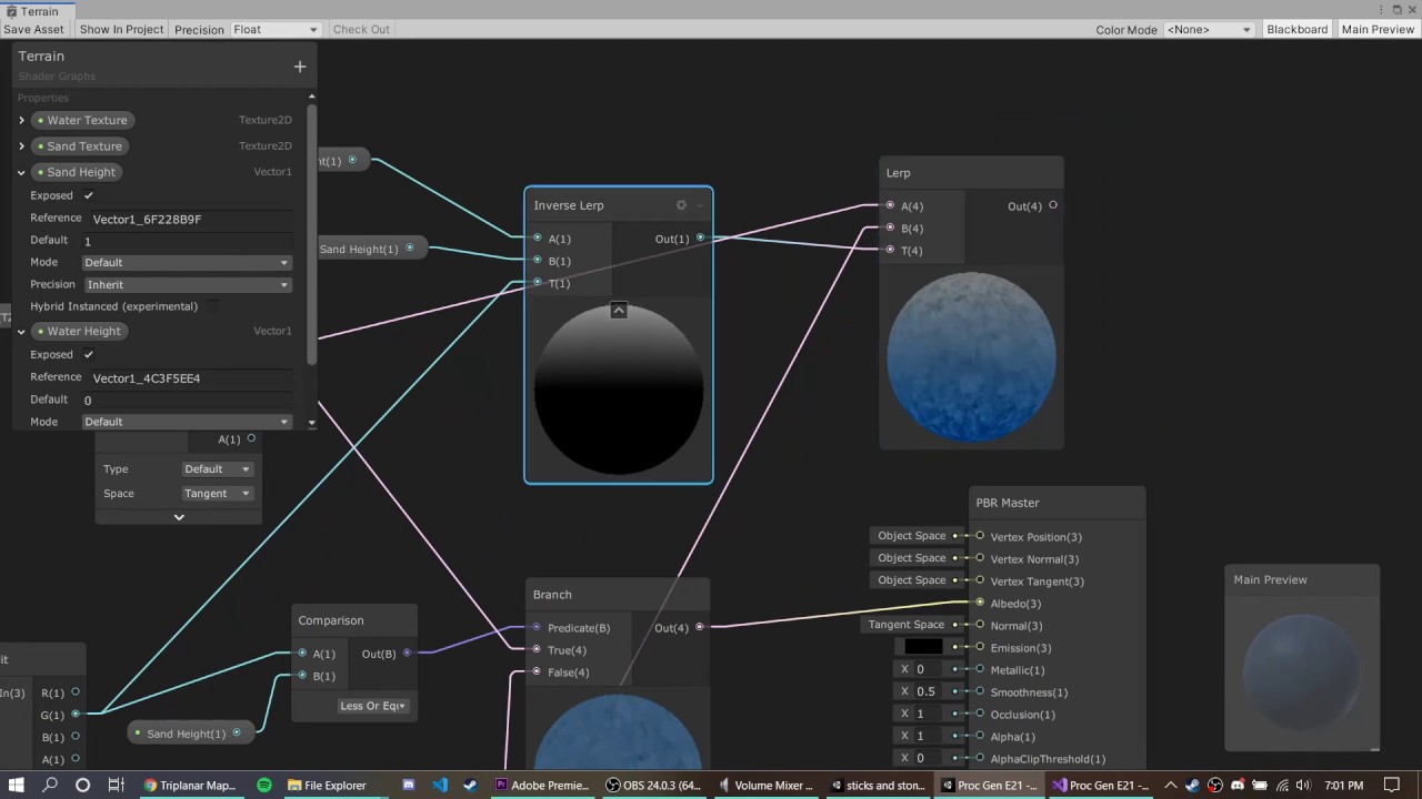
DOWNLOAD THE PROJECT HERE: https://github.com/jacklaplante/Unity-URP-Terrain-Shader
FOLLOW ME ON TWITTER: https://twitter.com/_snubber
This tutorial explains how to use the new shader editor graph to create a shader for procedurally generated terrain that works in the new Universal Render Pipeline in Unity.
Take a look at those other inputs for the PBR node
thankyou i fixed it i didnt realise there was a smoothness setting on the pbr node i thought them settings were in the inspector
When you make your own shader graphs, the only values that are exposed in the inspector are those you define in the blackboard
How do I use a custom compute buffer inside shadergraph using the custom node function? Im using DrawMeshInstancedIndirect to draw a bunch of meshes and the material I provide with is made with shadergraph. I have written a few shaders in code but since writing them is such a hasle I want to learn more about shadergraph.
this is my custom function in file
#ifndef SHADER_GRAPH_SUPPORT_H
#define SHADER_GRAPH_SUPPORT_H

struct Boid {
    float3 position;
    float3 direction;
    float health;
};
StructuredBuffer<Boid> boidsBuffer;

void GetHealth_half(in float instanceID, out float health)
{
    health = boidsBuffer[instanceID].health;
}

void GetHealth_float(in float instanceID, out float health)
{
    health = boidsBuffer[instanceID].health;
}

#endif
and this is how it looks in shadergraph

but I get this error: undeclared identifier 'GetHealth_float'
I can't tell you if this is still the best solution since I wrote my instanced renderer a few months ago. But I had the same issue and had to revert to a trick I found online somewhere.
I define a proxy function that initializes a global variable to the current element you're trying to access in the compute buffer. That proxy function needs to be setup in a custom function node like so:
#pragma instancing_options procedural:Configure
Out = In;
where Configure is the proxy function.
#if defined(UNITY_PROCEDURAL_INSTANCING_ENABLED)
StructuredBuffer<float4x4> instanceData;
#endif

float4x4 curInstance;

void Configure()
{
#if defined(UNITY_PROCEDURAL_INSTANCING_ENABLED)
    curInstance = instanceData[unity_InstanceID];
#endif
}
The Out = In is just so you can pass through a variable in shader graph, otherwise you wouldn't be able to connect the proxy setup custom node to your graph and it wouldn't get executed.
Then you can actually define your custom node that calls something like
void GetInstancedData_float(out float4x4 instance)
{
    instance = curInstance;
}
Shader graph nodes display the RGB data, not transparency - but it is there. Use a Preview node on the A output.
Depends exactly what you intend the texture to be used for, but typically you'd set the graph type to Transparent in graph settings and put this into the Alpha port that appears.
I have an example here which might help, https://www.cyanilux.com/faq/#sg-drawmeshinstancedindirect
Thank you for the idea, in graph settings i added additive blending mode too i think it fixed my problem with your suggestions
thanks a lot! I got it working now
Hello everybody, I have a strange issue with my shader graph on the initial load of my character
The skin shader is a custom shader graph I created and it work fine when I load a new scene after the main menu. However for testing purpose, I try to launch directly the scene I want with the character in it and that's when my shader doesn't work. Even if I delay the character creation by 30 seconds, once the character loads, his skin is messed up

The strange thing is that if I keep this scene playing, edit some script and go back to the scene still playing, the script reload and then, the skin shader gets displayed properly??

Would anybody know what's causing my initial shader issue?
Is it possible to use custom struct in shader graph?
don't think so tbh. probably only in a custom function node if so
Hey im trying to read a value out of a texture where i have baked the x,y,z coordinates into a texture. Now im trying to read those values in my vertex shader and apply the transformations to the vertices. The problem is my object is always transparent because the passed vertex coordinates are not right or the sampler doesnt work like i think it does.

What graphic format are you using for the texture? Textures often use a format with unsigned normalized values, which would clamp your coordinates outside of the range (0, 1). You would probably a format with regular float values.
Can someone tell me why for the love of my life my goddam tesselation shaders not working ```cs
...
#define MY_DOMAIN_PROGRAM_INTERPOLATE(fieldName) data.fieldName =
patch[0].fieldName * barycentricCoordinates.x +
patch[1].fieldName * barycentricCoordinates.y +
patch[2].fieldName * barycentricCoordinates.z;
        struct VertexData
        {
            float4 vertex : POSITION;
            float2 uv : TEXCOORD0;
        };
        struct Interpolators
        {
            float4 vertex : SV_POSITION;
            float2 uv : TEXCOORD0;
        };
        struct TessellationControlPoint {
            float4 vertex : INTERNALTESSPOS;
            float2 uv : TEXCOORD0;
        };
        struct TessellationFactors {
            float edge[3] : SV_TessFactor;
            float inside : SV_InsideTessFactor;
        };

        TessellationControlPoint vert (VertexData v)
        {
            TessellationControlPoint o;
            o.vertex = v.vertex;
            o.uv = v.uv;
            return o;
        }
            TessellationFactors MyPatchConstantFunction (InputPatch<TessellationControlPoint, 3> patch) {
                TessellationFactors f;
                f.edge[0] = 1;
                f.edge[1] = 1;
                f.edge[2] = 1;
                f.inside = 1;
                return f;
            }

            [UNITY_domain("tri")]
            [UNITY_outputcontrolpoints(3)]
            [UNITY_outputtopology("triangle_cw")]
            [UNITY_partitioning("integer")]
            [UNITY_patchconstantfunc("MyPatchConstantFunction")]
            TessellationControlPoint HullProgram (InputPatch<TessellationControlPoint, 3> patch, uint id : SV_OutputControlPointID)
            {
                return patch[id];
            }

            [UNITY_domain("tri")]
            Interpolators DomainProgram (TessellationFactors factors, OutputPatch<TessellationControlPoint, 3> patch, float3 barycentricCoordinates : SV_DomainLocation)
            {
                VertexData data;
                MY_DOMAIN_PROGRAM_INTERPOLATE(vertex)
                MY_DOMAIN_PROGRAM_INTERPOLATE(uv)
                return vert(data);
            }
            fixed4 frag (Interpolators i) : SV_Target
...
I think TessellationFactors of 1 means no tessellation. You'd need to set those to higher values. It's typical to use a property so it can be controlled from the material.
RGBA.Half
oh yeah wait I wasn't specifying what wasn't working, its that my mesh is completelly dissapearing which with a tesselation factor of 1 shouldn't be happening
and it also happens with 2 and so on
Ah okay... I think it's because you're using return vert(data); in the DomainProgram. That takes and returns a TessellationControlPoint struct (not Interpolators), which would be removing your SV_POSITION variable.
The idea is you're meant to have two vertex functions (kinda), one is the actual vert function that occurs before the tessellation stages and one after where you can have additional vertex displacement, if that's required. If not, just having return data; in DomainProgram is fine.
oh I see that makes sense, I have tried that now but its still not showing anything: cs Interpolators data; // tried VertexData here but no luck MY_DOMAIN_PROGRAM_INTERPOLATE(vertex) MY_DOMAIN_PROGRAM_INTERPOLATE(uv) return data;
Hmm, I can't see anything else wrong atm
Oh right, there's no transform to clip space currently
now it worked, don't know how I did not see that😅. Thanks a lot <3
Is there a way for me to create a graph that will write to the depth buffer without other rendering costs?
I'm trying to create some sort of depth mask which I'll use to prevent parts of other meshes from rendering. Is there a way for me to do this without rendering the depth mask mesh as transparent?
eyy, higher tesselation factors work as well

If you're in URP, an opaque graph (or transparent with ZWrite forced on) should already be generating a "DepthOnly" pass. Should be able to render it using a RenderObjects feature.
@regal stag Ugh, I get the desired behaviour but only when I override the material with a transparent one, which I believe will end up being the same in terms of rendering costs? How do I avoid rendering it at all?
Nevermind! Thank you, all solved
Is there a way to prevent the Unity shader compiler from striping out unused variables?
Hi, I really love this effect in games such as Tunic, Death's Door and Wonderbox, like inside a dense forest with some sun rays passing through.
Does anyone know how to achieve this effect? Is it using shaders or lighting effects? (or both)... I could not find any videos or shaders in the asset store that can do exactly like these ones.


Hello, I wanted to know if there was a way to basically replace the renderer with one that uses ray tracing, so I have more control of it. I'm doing this because I saw this video: https://youtu.be/Qz0KTGYJtUk
And I wanted to try to do it myself. I know there's HDRP but it also comes with a bunch of other things bundled in which eat performance.

I tried creating a custom ray/path tracing renderer. Featuring: maths, shaders, and cats!
This project was written in C# and HLSL, and uses the Unity game engine.
Source Code: https://github.com/SebLague/Ray-Tracing
Support the channel: https://www.patreon.com/SebastianLague
Coding Adventures Playlist: https://youtube.com/playlist?list=PLFt_AvW...
you can make a raytracing renderer and use that one instead...
Yeah that's what I meant
But like, how?
well the video you watched is allready a pretty good explenation but if you want a more step by step guide this is a pretty good one, although making a proper renderer requires waaaayyyy more work than this: http://blog.three-eyed-games.com/2018/05/03/gpu-ray-tracing-in-unity-part-1/
I know but since I want to try and make an rt renderer that's as fast as it can get, so it's more accessible I'm just gonna try to do it myself
ok then what is your question I gave you a pretty good recourse as a starting point up there
Nothing, just saying
Thanks
It looks like the spots are on every object, maybe even the once that are moving, so its probably not on the shader of each object. Maybe its simply done through lighting and shadow casting, or maybe its faked with a decal shader which would probably be the cheaper option
alright, thank you
hey, so i have a shader that shows a sprite on your screen, and some more stuff that only sprites can do. However, the sprite is a transparent image with transparent blur, but when the shader displays it, the blur is gone and replaced with black. Kinda hard to explain because I'm bad at explaining things so I'll show the before and after image.
To achieve the second image, i just filled the blurry parts in photoshop with the fill tool.
Anyway, is there a way to keep the blurry parts when the shader displays the image?
This probably didnt make any sense, so please tell me if you don't understand the question and/or if you want the shader code too.
Thanks :)


so the alpha is being cutoff
Since this video did not use rtx core to speed up the calculation, it's impossible to render this in real time. The performance will be much worse than HDRP.
So there's no way to get it to run well
There are two ways, the first one is using rtx core, the second one is using restir technique for path tracing sampling.
No like without having to have a special gpu with rt cores
I'll try restir
Which works without having to have an rt core right?
That's almost impossible if you want to run this in real time. The performance will be really bad.
30 fps is enough for me
Maybe even not 3fps if put this in game
If you really want to achieve some similar look in real time without rtx core
You can try vxgi, or SDF gi
Ray tracing is a very heavy effect on the GPU. Even if you have a 20 series GPU like 2060 or 2070, it's still hard to run ray tracing in real time in 30fps
Without dlss.
Really just want lighting to look good
Or well, more specifically, reflections, but like actual ray traced ones
Since that's part of why I'm doing this
Because screen space didn't work, planar didn't work
You can use a planner reflection and ssr, or using vxgi and SDF gi. Vxgi and SDF gi are still expensive but much better than ray tracing .
As I said both of those didn't work out
Why didn't they work?
Screen space was well, limited to the screen, so a lot of things looked pretty weird, planar reflections required you to set the height manually + only worked for 1 water surface
So I assumed ray tracing was the only thing left to do
And because URP doesn't have support for ray traced reflections
I just went with this
There's nothing I can do is there
Maybe like many games just using ssr if you have no rtx core. That is the limitation of rasterization.
As I said it didn't really work
And even if it did it requires the material to be opaque to work
Which isn't really good for water
Are you using a water asset or you make your own one?
using shader graph?
Yeah why
Because shader graph is hard to make the water support ssr
Something I do wonder though, is that I've seen other games with water that has full reflections and even other effects, and still run at very good fps
And on realtime too
That's a reflection probe
No
There'd have to be like
Thousands
On just a small area
And with almost full quality
So unless that somehow barely affects performance I don't think that's it
Might check out the shader and figure out what it is
That must be a reflection probe or a planner reflection if the GPU does not have rtx core.
But like
Don't planar reflections only work on flat surfaces?
And only 1 without any height variation?
Or is that just the asset I used
No, it can support other surfaces unless there are not huge curves.
I think it's actual ray tracing
Can you show me some images of the water you are talking about?

No clue?
I'll just look at the shader when I get home
And see how it's done
That's ssr.
Thing is it also renders things off screen
Or at least that's what I remember
But that doesn't fix the opaque issue
What can I do about that?
If you really want to make ray tracing, it's up to you. But I just want to tell you even if your GPU has rtx core, the real time ray tracing is still a fake ray tracing since. Doing the same thing as the video you share will be impossible to run in real time in real games.
Unless you do some sampling tricks like restir and have 4090
Well I just want to get some level of realism
For now
So I think I can get ssr to work but I don't know how to fix the opaque issue
Ssr required your material to have depth information, which is impossible to do in shader graphs. Buying an asset is a good option.
this can also be planar reflection
Well
Yeah but I just realized ssr didn't work because I didn't put fresnel in it
Not really
What the ssr asset does is basically replace metallic reflections with ssr automatically
But if the material is transparent it just stops replacing them for some reason
Yeah i guess
Does somebody know what the unity built in rp macro equivalent for UNITY_RAW_FAR_CLIP_VALUE is
Hey guys, so I imported these shaders into my project
Learn to write a toon shader for Unity engine with specular reflections, rim lighting and shadow casting.
However, they are pink and unity says there is no way to upgrade them and make them work with the current pipeline (URP)
Is there a way to upgrade them so that they work in the current pipeline?
No those are planar reflections, not ssr or even raytracing @grand jolt
Hi, There is a voxel world. I would like to highlight some specific voxels with certain types and render them on top of others (overlay). How can I achieve it?
Suppose a chunk has a mesh
what do you mean render them on top should they be like semi transparent so the voxel below is visible
Yes, probably I should go with semi- transparent for others but those specific voxels should be visible completely
Is semi transparent shader OK for a chunk mesh?
The appearance is not good, edges
Don't think so, unless they somehow managed to get the height right for all height levels
I am still unsure what you are trying to achieve with this
They are planar reflections, that is how they achieved those in source. This is 2004 tech LMAO
then how do I make them work properly for all heights
great, gonna do ssr
SSR + reflection probes would be the way to go in that case
what do you mean guys by work with all heights with what heights do they not work, I implemented planar reflection once and it pretty much worked all the time...
He means non flat surfaces
oh, I see, tbh. that surface up there is more than flat for planar reflections 😆
I am looking for a shader for Terrain that will exclude reflections in areas with shadows (like Filamented does on non-terrain objects). Does anyone know where I could find one? Using Unity 2019.4, URP

Comparison with a diffuse. The shadows should end up like this image below, but the reflections should stay wherever there is light.

hi ,
is it possible to generate a random value on shader frag between -1 and 1 ?
I also want to ask for advice
is it too crazy if I have 5-7 (if-else) statements in the shader frag function? .. Im still learning shaders and I was wondering if that is too expensive?
Hey I was watching this Blender low poly tutorial and he shows these edge highlights, does anyone know how you would get something like this in Unity?

He's just doing it with this "cavity" setting here ... I'm not sure how it translates to shader
Another question, does anyone know if it's possible to get Object IDs in a post process shader (using standard render pipeline)
Btw I have just gone back to standard pipeline from trying for ages to get shit working in URP and it's just so much easier
yes
static branching, not really, with dynamic branching it depends.. Its important to note that the compiler will restructure your code if it can to not actually require branching so: var b = value1 == value2 ? 1 : 0. There are unity keywords with which you can specify that the shader should specifically compile with an if statement. Now for if it is fast or not it really depends. Gpus are based of of wavefronts, to put it simple if statements can screw this up, and when it does a new wavefront has to be created data passed over which can be expensive. So not requiring an if statement but rather an expression like above is first better because you cannot really run into that problem second like pretty much every platform supports that branching type. Now to say how fast an if statement is hard to say cause its all kinda hardware dependent and specific to how you used them. You should check out unity documentation for static, dynamic... branching
probably with some flat shading and maybe some blurred wireframe shader could do the job
pp shaders aren't specific to any object... Its a fullscreen quad renderer at last, so what ids from what object do you want to get
could u give me a code example ?
just google white noise will give a number between 0-1 and then just remap it to your desired value
if pseudo random numbers is what you want
well for example like cryptomatte pass, you can see what object is being rendered by each pixel
aha, well not sure what cryptomat pass is, but I don't really know...
thank you so much but, the problem is I have a branching that consists of 4-12 branches ( 12 if & else if() statements), i dont think its possible to use the first method with 12 different outcomes.
since its based on hardware structure, do u think modern computers can handle it ?
would switch/case statement be a better substitute?
its not really anything I can say.. You will need to debug that. And even if it has slowdown because hardware can't handle it, I'm gonna say it shouldn't be bad, decent enougth. But if you want make your code as fast as possible there will always be room for change in some way..
Usually we have in graphics programing this "rule" that no shader should really take longer than two milliseconds
thats even worse
@lunar valley Thank you so much! ❤️
there is switch in hlsl? 😰
i have no idea
im sorry, one last thing , is there is a way to test how long does my shader take to compute ?
download RenderDoc, theres a really good unity integration
in there you can capture a frame and see timings for each object drawn
The sharper your edges are, the stronger the highlight will get as it seems, that part of it you should bake into vertex colors or uvs
could be calculated screen space, but that would look horrible when moving the camera
the rest of it is a kind of outline shader as said before
you can google that, its basically a texture where each object has a flat color
It's really important for my game because I'm relying heavily on custom post process shaders and I need the ability to apply them different for each object.
Which can be done in screen space but in order to do that I need object id / cryptomatte
pp is a fullscreen effect, I don't think unity has such a thing for you. Maybe you can make each object write to a texture and set it to specific color? but just rambling around now.
That's a good idea ... can you overwrite certain parts of a runtime virtual texture? Like accumulate different objects into the same image
I think you are onto something
If I make two cameras which each render their own postprocess shader output to a Render Texture then a full screen overlay which composits them together
I kinda think the performance / resolution will be trash but it probably would work
that might work...
Sure, but switch statements (in pretty much any language) compile down to a bunch of conditionals and branches, same way if/else sets do. It's probably syntactic sugar. At the low level code of any processor it ends up being <compare, branch ne next check, do stuff, bail-out>, <compare, branch ne next check, do stuff, bail-out>, etc. At least that's my guess.
You can try researching "barycentric coordinates"...they're used to tell how close to an edge you are.
But that effect might not be such, because intensity varies. Or that's just lighting, not sure.
Oh yeah, I remember why that render texture approach doesn't work. The render textures are accumulative so you basically end up with wacky Windows 98 shit like this

Clear the render texture between frames......
In a script?
yeah.
I am currently trying to render a sphere on a quad. The normals are close but not quite correct. Is it possible to achieve the same carvature as the real sphere on the shadows?

Its pretty simple currently

🤔 try adding power by 2 node before outputing to vertex
Yeah... could guess that's how they worked, but never actually used it or seen it used anywhere, probably for a reason 😂
Doesnt work. Looks like this

this covers everything
Yeah thx. I know this blog post. But it uses path tracing which seems to be a bit overkill for my use case. I am trying to make it cheaper
It does not use path tracing, it uses intersectors https://iquilezles.org/articles/intersectors/
Articles on computer graphics, math and art
I've used it in a shader before, runs smooth even on mobile and webgl
cause there is no looping, most expensive thing in there is probably that square root
(and if you want it to look correct, there is no cheaper way, because how the camera frustum behaves)
Yeah the problem is I need to combine it with a quite complex shader graph shader that already exists. The solution from the blog post does not wor with shader graph so I would have to rewrite the existing shader completely 🤔
I would like to avoid that but keep it in mind if I cannot find another solution
I mean probably you'll need to write to the depth buffer and that's not possible in shader graph as far as I know
because currently I'd imagine your object does not play well with other nearby objects
Yeah thats right. But luckily it doesnt need to as there will not be any clipping objects
Ah, okay
@worldly drift Don't output in the vertex normal, but in the fragment
As it will only output to the vertices, and is then linearly interpolated
Ah I see. That makes total sense 😅
But that would mean calculating the lighting in shader graph would it? There is no vertex input for the fragment block.
It's an unlit shader ?
No its lit. But there is no vertex position input node for the fragment part is there?
No.
Bu you can output vertex position in the vertex stage, and normal in the fragment stage
Oh yeah I meant Normal not Poistion. And obviously there is a normal output in fragment shader
But shouldnt this work then?

Close, but it's not fully correct to mimic sphere normals.
You should use sin and cos.
Let me quickly set it up and screenshot

Applied to a quad it is still missing the depth information of a sphere, but you get close :

Wait no, forget this, it's wrong
Hello, guys. an apology, I don't know where to post this. A few days ago I have been experiencing a brutal performance drop in my game (in editing) and now I realize that at NO TIME has it used the graphics card. This is fucked up because slow editing is the worst. The graphics stays between 0 and 0.5% (ridiculous oajsdkjaskljd). What could I do to fix this?
@worldly drift I'm probably to much comfused to get why I can't make it with trigonometric operations that should be fully exact.
This one is quite easy though, and ok-ish :

Not post on every possible wrong channel atleast
Oh thx that is exactly what I was looking for. Did not know about the Normal Reconstruct Z node 🙂
Hey I'm not sure if I'm in the correct channel but I'm having an issue using a tilemap which provides an infinite looping background. The camera is locked to my player and as the player moves toward the edge of the tile a copy of the tile is placed at the edge to give the feeling of a continuous background.

The scene works perfectly when I run it in the editor but when I build the game to desktop everything is pink unless I set 'Clear flags' from 'Don't Clear' to 'Depth Only', in which case you can see the tilemap fine but at the edge where it should be showing the next copy of itself it only shows pink.
So whilst I'm aware that pink usually means the render pipeline and materials don't match I'm not sure that's the problem in this case
this is how it should look

Pink doesn't nesseceraly mean that, it simply means there are compile errors of any sort
this is how it looks when I build it (in 'depth only' mode)

I'm getting this compile error:

And I have no idea what that means
Also if I set 'Clear Flags' to a bg colour that colour does show up

is it possible to use shadergraph to render an object twice?
No, you'd use another material, clone the object or use the RenderObjects feature if in URP.
👍
Would it be correct to say that GPU accelerated painting shouldn't be used for a simple guess-the-drawing game with 1 brush preset? Idk how likely mobile GPU stalls with big brush radiuses would be. Is drawing usually implemented on CPU in such usecases?
Why GPU would stall and CPU wouldnt?
How do I use an enum block palette from my C# class in a compute shader for voxel terrain? There doesn't seem to be an enum type in HLSL
no there isn't use integers instead
hm
That won't work, I don't think
I would need to allocate all the regions of block types by hand and that is impossible
The advantage of being able to use an enum-like structure is that I could add values on the fly without having to double check the hard coded int values, as the enum names would always be the same, in case block identities were changed. Is there anything that might allow me to achieve a similar thing in HLSL?
Idk, a huge burst of drawcalls for a big line and a weak GPU 😅
if I have a texture like a noise texture, how can I add color to the black parts of the texture?
I thought about something like splitting the color out and using an add node but that seems like a mess
no
How cordial
simply check if the color is black using a branch node
im just getting into shaders, does shader graph replace coding?
interesting, would I feed a comparison node into the predicate? never seen branch nodes before
ty
now is the time to research how they work^^
well this was helpful enough I suppose. Thanks
Is there a gospel to setting numthreads in a compute shader?
My chunks are 10 by 10 by 10; is it unoptimal in some way to have 10x10x10 threads?
yes, the numthreads you specify will depend on your usecase. In your case your 10x10x10 chunks will be computed in one wave front, which is probably more optimal than 10x10x10 wavefronts per chunk but this depends on what else you are computing with your chunks. If per chunks you are computing like 256 verts then splitting up the work like this might be better.
I don't understand your 'wavefronts' analogy, sorry
What situations are you comparing when you say "probably more optimal"?
My [numthreads(10, 10, 10)] as opposed to?
when you are working with compute shaders you should get yourself a bit of some basic gpu hardware knowledge. gpus work on wavefronts with each wavefront you can specify thertain number of threads.
hey guys, does anyone know UnityInstancing.hlsl and DOTSInstancing.hlsl well enough? specifically in regard to HDRP real-time lights
I just tried 2023.2a (after 2022.2) and my meshes (drawn via indirect calls) don't receive lights. gbuffer and shadow maps look ok though
is there an easy way to toggle a pragma shader wide instead of on a material by material basis? Like a bool I can set in the shader inspector and affect all materials
By pragma, I assume you mean keyword defined by either multi_compile or shader_feature. If so, you can set global keywords with Shader.SetKeyword. But if any other shader has a keyword of the same name, it will also be set on those shaders.
yeah that's exactly what I meant. I assume I'd need to write a custom inspector for the shader/set this in an editor script somewhere?
Yeah, this would have to be set from a script.
These keywords are not saved, by the way. Setting them from an editor script will only persist for that editor session.
does anyone know of a good NON-URP triplanar shader guide
why non-urp
because I would like to learn a bit about writing shaders
writing as in code shaders?
yeah
Any particular reason you are trying to do a triplanar shader?
also I imagine you can search for it without unity and if your goal is to learn you should be able to adapt it to unity shader code (if it even differs!)
this might help either way, probably cant follow it exactly, but still useful
https://www.youtube.com/watch?v=s79Zu0F8fu
𝖣𝖾𝖺𝗋 𝖴𝗇𝗂𝗍𝗒 𝖥𝖾𝗅𝗅𝗈𝗌,
𝖨 𝖺𝗆 𝗂𝗇 𝗇𝖾𝖾𝖽 𝗈𝖿 𝖺𝗌𝗌𝗂𝗌𝗍𝖺𝗇𝖼𝖾 𝗋𝖾𝗀𝖺𝗋𝖽𝗂𝗇𝗀 𝖺 𝗐𝖺𝗍𝖾𝗋 𝗌𝗁𝖺𝖽𝖾𝗋
gonna have to be a tad bit more specific
what kind of water shader?
stylized? realistic? ocean? pond? river?
etc.?
𝘛𝘩𝘢𝘯𝘬 𝘺𝘰𝘶 𝘋𝘢𝘷𝘪𝘥 ,
𝘪 𝘸𝘰𝘶𝘭𝘥 𝘴𝘢𝘺 𝘢 𝘚𝘵𝘺𝘭𝘪𝘻𝘦𝘥 𝘴𝘩𝘢𝘥𝘦𝘳 ? 𝘪𝘵 𝘪𝘴 𝘧𝘰𝘳 𝘢 𝘱𝘰𝘯𝘥
you don't have to be so formal lmao
but anyways
is this something that you are making?
or are you looking to find an existing shader?
𝘠𝘦𝘴 𝘴𝘪𝘳, 𝘢𝘯𝘥 𝘢𝘯 𝘦𝘹𝘪𝘴𝘵𝘪𝘴𝘵𝘪𝘯𝘨 𝘴𝘩𝘢𝘥𝘦𝘳 𝘸𝘪𝘭𝘭 𝘥𝘰, 𝘮𝘺 𝘷𝘦𝘳𝘴𝘪𝘰𝘯 𝘰𝘧 𝘶𝘯𝘪𝘵𝘺 𝘪𝘴 2021
what render pipeline?
𝘪 𝘵𝘩𝘪𝘯𝘬 𝘵𝘩𝘢𝘵 𝘮𝘢𝘺 𝘣𝘦 𝘸𝘩𝘦𝘳𝘦 𝘪 𝘢𝘮 𝘩𝘢𝘷𝘪𝘯𝘨 𝘪𝘴𝘴𝘶𝘦𝘴
what? not knowing what render pipeline your on?
𝘺𝘦𝘴, 𝘪 𝘴𝘦𝘦 𝘪𝘯 𝘮𝘺 𝘴𝘦𝘵𝘵𝘪𝘯𝘨 𝘏𝘋𝘙𝘗 𝘨𝘭𝘰𝘣𝘢𝘭 𝘴𝘦𝘵𝘵𝘪𝘯𝘨𝘴?
oh so you are using hdrp
𝘐𝘴 𝘵𝘩𝘢𝘵 𝘨𝘰𝘰𝘥 𝘰𝘳 𝘣𝘢𝘥, 𝘪 𝘵𝘩𝘪𝘯𝘬 𝘪𝘵𝘴 𝘥𝘦𝘧𝘢𝘶𝘭𝘵?
honestly neither, but the real question is whether or not its good for your project needs
also my trees have respawned pink
for a stylized project personally I wouldn't use HDRP
what would u reccomend
URP or the classic built in pipeline
okay ty
but I would first ask if you have reference images to the kind of water you want to emulate


are you willing to spend money on a shader?
some of these look like screenshots of existing packages you can get
up to $10
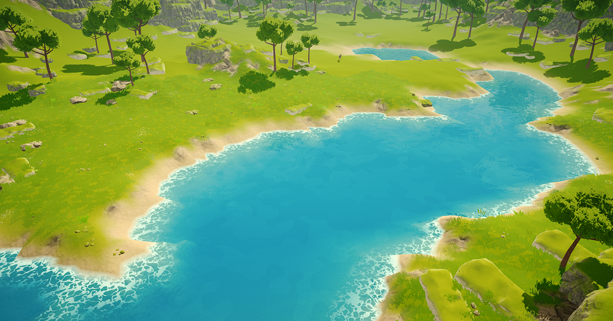
Add depth to your next project with Stylized Water Shader from Staggart Creations. Find this & more VFX Shaders on the Unity Asset Store.
this might work
thanks
how can i make a cutout surface shader
Hello humans, silly question here, I can't see any of my .PLY files in my game tab, I can see them in the scene tab, and the plugins are installed but it won't show up in the game scene 😦
(it's not a clipping issue)
Trying to make a transparent surface shader that can recieve shadows, but running into some issues with z-order
When i use the transparent render queue the order is correct, but i cant recieve shadows

using any other render queue causes it to render behind everything else

Pastebin
Pastebin.com is the number one paste tool since 2002. Pastebin is a website where you can store text online for a set period of time.
the shader itself is just a simple surface shader
Burst of draw calls?
I'm using shadergraph to create normals for a plane. It's very simple, 5 nodes:
Perlin noise => Gradient nodes X and Y => Combine => Normalize
The issue is that with large scale perlin and a far-away camera, crazy moire patterns emerge quickly. Is there any way to fix this? I couldn't find a way to downsample the perlin
Hello there, this may be kinda a beginner question, I have a sprite graph where I modify my sprite to have the effect I need, and one of those effects is basically making a buble around my sprite.
The problem I am facing right now is that my bubble effect does not appear using the alpha channel of the graph, any ideas of what's causing it?
This is the sprite

this is the effect

this is how it should look

and this is the result, as you can see, it seems like some parts of the alpha try to render that way, but it results in weird artifcats (look around the head band, I kind of a triangle formed there)

I asume this is happening due to my sprite import settings, but I have very little knowledge on 2D, so Im not sure of how my sprite settings should be
is this tile selection thing a shader? https://cdn.discordapp.com/attachments/532260045887373352/1110397343846637668/image.png

So what you think is shader?
not sure, are they dynamic materials?
Everything rendered by Unity uses a shader, so I suppose it also uses a shader.
No clue what you mean by dynamic materials. I dont see anything in the picture that would not be possible without custom shaders but thats just still image. The effect, whatever it is, could be easier to create using shaders tho
Most likely image(s) and line renderer
I'm trying to educate myself on HLSL, and I'm trying to get my head around rendering to a texture in one pass, and then using that texture in a subsequent pass. I feel like I've googled around quite a bit, but I can't seem to find a concise explanation of how to do this. Can anyone point me to a resource on this?
A shader has one specific output target, it cannot have more, except compute shaders
Perhaps I'm phrasing it incorrectly (which is probably why I'm not finding anything). In short, I'm trying to understand how to calculate some stuff in pass1 and then use the results of those calculations in pass2.
it could be done in multipass
pass 1: render the object with texture just as usual
pass 2: grab the output using grabpass into a rendertexture
pass 3: do something with the rendertexture
If I understand you correctly, this would mean that I would be using the frame buffer to pass data between the passes. Is that right?
yes, I think it does use frame buffer
Is there no way to just declare a texture or struct that is scoped to both passes?
🤔 that's what I'd like to know too actually. Using framebuffer means I can't use the grabpass method for transparent shader since the buffer will be polluted by anything drawn before (under) the object
The more I look around the less possible it seems. If I figure anything out, I'll certainly let you know
Well, painting is basically just stamping the brush texture for every pixel of the path, so a draw call for every stamp.
I dont know how that requires many draw calls but whatever. I still dont understand how doing things one pixel at a time on CPU would be faster
Not faster, just less sus to do on a budget phone in a dumb 2d game maybe?
hey, anyone else having issues with the noise nodes on stable? All noise nodes are completely grey instead of noise for me
Sounds like you are giving it a constant coordinate as input
Noise functions are just mathematical functions afterall, if you give same input, it gives the exact same output
Thanks for the reply! Turns out I just had to update to a newer version it was a bug that was fixed a few weeks ago.
@agile token It totally can, that's how deffered shading is done. With a declared output structure : https://forum.unity.com/threads/multiple-fragment-outputs.283013/#post-1867683
Unity Forum
Hey!
As I continue studying shaders I'm trying to convert a shader from some dialect (probably GLSL?) to Unity. It seems that in Unity fragment...
Reposting my question from yesterday, anyone have any ideas
@agile token Else, what your are trying to do sounds like multiple blits with render textures
I understood him competelly wrong I thought he meant something else. I thought he meant like a fragment shader which sits on an object while also writting to a seperate texture at the same time or something
also, don't ping me
I've written down "multiple-fragment-outputs" and "blits with render textures". I don't know what they mean but I will read up on them. I found a little bit about "Multiple Render Targets", but I'm still reading. It seems crazy to me that there is no easy way to pass data from one Shader Pass to another.
It's just how it works 🤷♂️
Thank you for your help. I will look into all that you have mentioned
Is there any way I can control the z-depth of a transparent surface shader in a non-transparent render queue?
I’m writing a fog plane shader that needs to be able to receive shadows
When I’m on the transparent render queue the z order works correctly, but changing to a non transparent render queue always make it render behind everything else
For context, my environment is made up of sprite renderers and tilemap renderers, I know that these use the transparent queue by default but I’m assigning a surface shader material to them, and their render queue is set to geometry
The fog planes however are quad mesh renderers
I have a feeling this discrepancy is the source of the problem but I’m not sure what can really be done to correct it
Do sprite renderers override their render queue or something?
hi, i implement stencil to my shader unlit for sprite, but instead of gradually showing it self it just render everything the moment it touch the mask rect UI component, i want it to render like the plane does,did anyone know how to fix this?
i am using this ;
Stencil
{
Ref 1
Comp Always
Pass Replace
}
and i use screen space overly for the canvas
Is there any documentation about this node? Does it work with the quality settings set in the project settings?

I think in HDRP it exposes Material Quality settings somewhere (maybe pipeline asset / camera?). URP doesn't seem to have that, but should be able to set the keywords through MaterialQualityUtilities.SetGlobalShaderKeywords. https://github.com/Unity-Technologies/Graphics/blob/master/Packages/com.unity.render-pipelines.core/Runtime/Utilities/MaterialQuality.cs
Or just use your own Bool/Enum Keyword
Thanks!
Hey guys 🙂 I'm quite new to shader programming so I might ask a rather trivial question but i ran into a problem which i don't really understand.
When trying to calculate shadows using the main lights "light.shadowAttenuation" it results in jagged shadows on my sphere. All other shadows casted by the object look pretty good. Anyone who can explain to me why that happens?


its because of the shadowmap
normally you wouldn't be seeing those shadow issues since that area would be in complete shadow
i don't really know what that is 😄 but thanks for that buzzword, i will take a look into this
shadowmaps are essentially "shadow textures" rendered from where a light is placed
they are the standard technique when it comes to creating shadows for light sources
they have their own set of issues though, namely in that they have a set resolution, but also when not configured properly can introduce alot of aliasing artifacts (shadow acne namely)
what your seeing there is like I mentioned, is the shadow acne and aliasing issues that are hidden from view because normally with a regular NdotL lighting model those artifacts would be completely hidden
but since it looks like you are using a custom NdotL lighting model, your going to be running into those issues
this is shadow acne for the record if you need to see another example

I see, so there eighter might be a configuration problem with my shadow settings somewhere or my NdotL model is the problem. Since i don't know what the NdotL is (I guess something like the dot product of normal and lightdirection?) that might be the problem here
yes that would be your NdotL, baiscally your main light shading product
there are ways to mitgate it
for one, with your NdotL product I would make sure that the lighting doesn't go past the main line
I'll show what I mean

ignore the names in here
but the one on the left is your classic NdotL
you can modify it to make it so that it wraps around like the one in the middle
but the issue with that is if you are using shadows, like I said you will expose that shadow acne that is meant to be hidden normally with the classic NdotL
so basically the solution there is basically to avoid wrap lighting (or at the very least, make sure that the lighting doesn't go past the point where things should be in shadow)
the second solution I have in mind is simply adjusting the shadow casting settings on your lights
adjusting the bias and normal bias factors
hi ,
Im trying to pass either uv.x or uv.y to the frag shader as a parameter, how do I do that ?
im trying to optimize my shader code as I have few braches if-else statements that I was adviced aganist by a few.
and correct me if I'm wrong but, frag function runs every frame ! (that is an if statement runs on each frame for each pixel)
i wanna move the if statements else were and only send a value of float2 as a parameter, what are my options ??
can I do it in c# ? , is it possible to get the uv.x or uv or uv.y as vector2 or vector 3 in c# and maybe pass it to the shader as value of float2/float3 ?
may I ask why?
normally what you would do if you wanted to use the UV parameters is define it in a struct, assign it in the vertex shader, and then use the final value from there
case and point

appdata which is the model data

then in the struct that is used by the vertex shader, you define a field for the UV coordinates

then define the actual value in the vertex shader

and then in the fragment shader, to use the UVs from the v2f (vertex to fragment) struct
examples come from here
I should be able to get the shadows from the 2. picture by using NdotL * 0.5 + 0.5 or something like that. But using this would also result in shadow acne. Sadly changing the bias of the lights only gets me to a certain point. There are still artifacts 😦
yes adjusting those shadow settings wont completely eliminate them, which is why I said that you should avoid NdotL products that will wrap your lighting. There isnt much you can do to fix those issues with shadow mapping
https://64.media.tumblr.com/e372b61adb77f2adf2601b2e97e2a7fa/tumblr_inline_nqtgw1fo3n1ri0s9d_540.jpg

notice here how it doesn't wrap around
multiple paths with serval different purposes , for example, Its a bit complex shader and a bit out of my league but with options I m able to make many variaty of shapes from the same shader instead of making several shaders for each.
so I would like to just make the decision on C# and just pass it to the shader for it to use it
which would keep it optimized since I dont have to go through all the hadious braching statements on each frame for each pixel
what kind of shader is this? to my knowledge I don't think you would be able to pass UV coord data through C#, since remember that in the fragment shader (which runs for every frame for every pixel), if you pass UV coord through C# that means that the UV coord will be the same value for every pixel since you have no control over where exactly you could change it
so I still don't get how the common approach i.e. this wouldn't suit your needs?
UVs typically are calculated in the vertex shader, which unlike the fragment shader run for every vertex (instead of every pixel) so it's pretty fast
also if your trying to optimize your shader by avoiding using if-else statements, why not use shader keywords and preprocessing blocks?
using an if directive?
makes sense, i might need to rethink my approach there. The cell shading 3 cuts is basically what im aiming for. I'll get back to my testing lab 😄
@prime shale
Imagine having a liquid that deforms into some objects or strings or gases, I just need to know which one is it
they are all similar in terms of equation, I just need to pass few parameters instead of having to check on each pixel
example
gas eq: uv.x * foo
liquide ux.y * foo
so i cam to the concolusion that all i need is to make float2 and send its value
float2 state;
newState = state *foo
if I could just change the valure of state by uv.x or uv,y then I wont need to run a check every pixel for every frame
is this a compute shader or a regular shader?
I'm geussing regular since you mentioned fragment
yes its fragment , i m still learning I dont even know what compute is lol
still a bit confused, so are you just trying to avoid running the fragment shader (i.e. ignoring certain pixels) depending on the UVs?
because in a case like that I think your going to have to be checking every pixel, I don't think there is a way around it
oh wait , does the uv.x value change for each frame and each pixel ?
yes
ohh!!
well it doesn't change for every frame necessiarly
I mean if we want to be pedantic, it depends, technically it can, sometimes it doesn't
but assuming that this is in the case of like a regular object shader, the UVs will be different for each pixel
but wait , that is irrelevant in my case
because i m trying to tell the frag to use uv.x on each frame for each pixel whatever its value is
quick question
so it can change however it like as long as it's uv.x then the function should return the right result
if your looking to optimize, why not move it to the vertex shader?
if your worried about performance?
that way you'd be computing per vertex
instead of per pixel
it havely relay on the pixel itself and not the vertex
but if i could tell the function to use uv.x next time it run through the vertex function then I think that would also be a good move.
ultimately if i could do the switch from c# that would be great , i think unity should do something about it , a function that runs 1 time on change
like ( start() )
forgive me I'm still not following and feel like I'm misunderstanding you quite a bit. Can you step back and explain what you are doing, what this shader is, and what you are trying to do?
I have a gut feeling that is telling me that whatever you are trying to do, there is most likely a much easier way to go about it lol
but just to avoid any misunderstandings can you explain in detail what this shader is, and what you are trying to do
well as I mentioned a very simple example
I have optimized many shaders in the same function but to keep it simple Im just talking about 2 simple example
the only different between those two functions is one of them uses uv.x and the other uses uv.y
float2 state;
function :  state *foo
if I could do a check outside the shader function to tell the shader use the uv.x as the value of state then that would be the best optimized solution as for shader all it do run on each frame and on each pixel without any branching or what so ever while c# defines few parameters within the function ( example , use uv.x or uv.y )
directive?
#if USE_UV_X
#endif
so your wanting to avoid using dynamic branching
which is fine and ok, dynamic branching can have runtime performance impacts
so in a case like that, use static branching
i.e. through directives and shader keywords
it has no runtime impact unlike dynamic branching, and it does what you are most likely trying to attempt
that would be your solution
ohh , hmmm that might be a good idea but I usually use those to check if user is on pc or android , u know the general big things, how reliable is that?
its reliable? not sure what you mean by that
your defining your own directive/keywords though, your not using existing ones
how do I change the value of float2 state to uv.x ?
your asking to change the value of a float2 to a float?
nah , i dont know how to use the derivative to change the vlaue of any variable ?
ok
in your example you mentioned that you want to have a function switch from using uv.x to uv.y
yes?
without using if/else (i.e. dynamic branching)
yes!
#pragma shader_feature_local USE_UV_X

float myFunction(float2 uv)
{
      #if USE_UV_X
             return uv.x;
      #else
             return uv.y
      #endif
}
Sweet thanks but can I change the value of USE_UV_X dynamically ?
Yes
then yes
I'll show one more example
I have a custom shader I wrote for volumetric lighting, and I have an option to where the user can enable animated noise if they want to

so I have a property here that is togglable through the material interface
(this doesn't have to be through the material interface, this is something that can also be set thtrough c# code if you desire)

in the main shader I have to tell unity that this is a keyword within the shader that is togglable
so what this does is that it will basically in the pre-processing step of the shader, compile a shader variant (basically another version of the same shader) that uses whatever you have defined with that keyword

a bit complex here but I wrapped most of this in the keyword
so if the user wants animted noise, I have code in there for doing animated noise,
and if the user doesn't want it, then the simpler function is used
with the keyword here, basically two versions of the shader will be created and compiled (and can be switched at runtime), where one uses the code inside the if block, and the other will use the code inside the else block
does that make sense @pale python ?
this is what we call static branching
yes thanks so much for sharing but how do u change the value of _ANIMATED_NOISE ?
in c# ?
oh!! i dont need to add it to the directive of the whole project ?
the one under performance menu
ohh i cant believe it , this is awesome !!
just to be sure , i dont need to add it here

for android or pc or any built, that has nothing to do with the shader , ocrrect ?
@prime shale thank you so so much , this is fantastic ! , no need to use dynamic branches anymore ^^
Be aware though its not like its completely free
These will introduce shadee variants, and too many could cause issues down the line
I.e. long build times and others
But since i imagine your proritizing runtime performance then that would be the way to go
ohh , is 20 variants is too many ?
Nah
perfect 😄
Well 20 keywords would be alot
oh
oh but can i use a keyword / int like #if ANIMATED == 1 ?
that way I can use only 1 keyword for many
Ehhh not quite
Pre processing is not really for "runtime" checking so to speak
Hmm how can I phrase it
If you have values that will change at runtime frequently then dynamic branching will have to do, but if say (using my shader example) you wanted a version of the shader with animated noise, and one without animated noise. You can switch between them at runtime by toggling those keywords
In the example you told me you wanted two versions effectivley of a function that would use one thing, and one that uses another. Keywords will help you there, but keywords will not help you if you wanted to check the value of a certain thing at runtime within the shader
Does that make sense?
Hoping I explained it ok
sort of :S , yeah unity should really make a tiny reference upgrade that we can just use to shader, but I can imagine a good combination between keywords and dynamic branching would help
Thank you so much @prime shale ❤️ ❤️
you have really saved my day !
How can I implement voxel based cellular automata in a compute shader?
For each voxel, I should get its neighbors.
There is a 3d array for voxels
Should I get the neighbors of voxels and add them to that voxel struct?
I want to get neighbors efficiently
So you mean make each voxel also save its neighbours? I dont see how that would be faster in any way. You would then need to update the neighbours of the voxels too when the voxels update. Just getting the neighbouring cell from the 3d array isnt really that slow
so i have a really newbie question about shaders. i don't know the first thing about programming them yet but i picked up a shader asset that lets me palette swap my sprites by changing the material. i got it working just fine in a 2d urp project but now im' trying to use it on a spriterenderer in a 3d urp project and it's not changing the colors with material. i'm pretty sure i set it up right, do some 2d shaders not work in 3d even on 2d assets like spriterenderers?
there shouldn't be no
OK, so is the standard way to get neighbors using indices?
How then if not using indices?
I need help with making a pixel perfect sobel outline shader
OR really, any 3D outline shader
Or alternately, help with the ProPixelizer assets, which I can't get working correctly.
Anyone here who has experience with any of these three things?
I've got both a sobel fullscreen outline shader, and propixelizer's outline implementation, but I can't get either of them working the way I need.
My fullscreen sobel pixel perfect outline shader can't render 1 pixel thick outlines, no matter what I've tried, (as seen in the posted image)
While, at the same time, propixelizer throws up huge glaring errors if I try to follow the usermanual tutorial on making copies of the shader for modification, no matter what I do.

And here's the Sobel Filter HLSL file that I'm trying to use. I thought I could use the DepthSobelUnderlay function I made in order to remove outlines based on if a pixel is the highest depth among its neighbors, but for some reason I can't understand, all this does is make the outlines turn a darker grey, without removing any of them
Pastebin
Pastebin.com is the number one paste tool since 2002. Pastebin is a website where you can store text online for a set period of time.
Hey guys, I want to create this shader graph effect and need your help:
A plane with a texture on it with it's alpha set to 0(making it transparent), but only the part of the plane that has the mouse pointer over it will be opaque..
I'm not good with shaders, so I have no idea how to design this..
you could maybe get the mouse position from c# (not sure if its possible to get it in hlsl), then transform the pixel coordinates with the depth all the way back to world space. And then simply use the distance value for the alpha. not sure how well this would work tho
idk. maybe viewVectord normal?
I said. One way is to get all neighbors and store them for each voxel outside the compute shader.
For example voxel 0 has neighbors voxel 1, ...
The latter way is to get indices of neighbors in the compute shader
No idea how to do any of that...
well you have got a lot to learn then
how do you sample the NormalWorldSpace in hlsl? I know you can get Scene Depth and Scene Color using
SHADERGRAPH_SAMPLE_SCENE_DEPTH and SHADERGRAPH_SAMPLE_SCENE_COLOR
but is there a snippet of code I can use to grab the NormalWorldSpace? There's a node for it in the shadergraph, so it should be possible, right?
there is the normalVector node
Yes, but I want to get it in hlsl code
just pass it into the custom function as an input
both normalVector and URP Sample Buffer output a vector3, I need a texture2D that I can sample at various uvs inside the hlsl include itself.
// This function runs the sobel algorithm over the opaque texture
void ColorSobel_float(float2 UV, float Thickness, out float Out) {
    // We have to run the sobel algorithm over the RGB channels separately
    float2 sobelR = 0;
    float2 sobelG = 0;
    float2 sobelB = 0;
    // We can unroll this loop to make it more efficient
    // The compiler is also smart enough to remove the i=4 iteration, which is always zero
    [unroll] for (int i = 0; i < 9; i++) {
        // Sample the scene color texture
        float3 rgb = SHADERGRAPH_SAMPLE_SCENE_COLOR(UV + sobelSamplePoints[i] * Thickness);
        // Create the kernel for this iteration
        float2 kernel = float2(sobelXMatrix[i], sobelYMatrix[i]);
        // Accumulate samples for each color
        sobelR += rgb.r * kernel;
        sobelG += rgb.g * kernel;
        sobelB += rgb.b * kernel;
    }
    // Get the final sobel value
    // Combine the RGB values by taking the one with the largest sobel value
    Out = max(length(sobelR), max(length(sobelG), length(sobelB)));
    // This is an alternate way to combine the three sobel values by taking the average
    // See which one you like better
    //Out = (length(sobelR) + length(sobelG) + length(sobelB)) / 3.0;
}
Like how in this snippet, rgb is sampled directly from an hlsl function
what do you mean you need a texture2D? You mean a normal map or the meshes normal?
I need an equivilent to SHADERGRAPH_SAMPLE_SCENE_COLOR(), but for the NormalWorldSpace render instead
that I can use in hlsl, and sample at UVs of my chosing from within the code itself
since I'm wanting to run a sobel over it
ah thats what you mean, tbh. not sure how you would do this in urp, in built in there is something called depthnormals, maybe you will find something equivalent to this but for shadergraf urp
There is no equivalent iirc as there is no normal buffer.
You can however add your own normal buffer with custom renderer features, that's how the URP ambiant occlusion works.
To my knowledge, you can even access the AO normal buffer if it is active, avoiding you to write an additional renderer feature
I'm not sure if there's a macro specifically, but should be able to include and use functions from https://github.com/Unity-Technologies/Graphics/blob/master/Packages/com.unity.render-pipelines.universal/ShaderLibrary/DeclareNormalsTexture.hlsl
Otherwise just declare and access the texture like that does
That assumes the normal buffer is generated like Remy mentions. In Forward, would need a renderer feature. In Deferred, probably always generated since it's part of the gbuffers?
What is "Custom Render Texture" in shadergraph? I can't find any documentation for it

It's used on materials used on the Custom Render Texture asset. https://docs.unity3d.com/Manual/class-CustomRenderTexture.html
ahh. So not what I'm looking for, in trying to get a camera to output its normals to a render texture that I can use for other stuff, then?
For URP you can use a renderer feature with m_ScriptablePass.ConfigureInput(ScriptableRenderPassInput.Normal);. If you're using the SSAO feature (with normals source), it's already doing it for you.
Can you increment an integer field on a compute shader thread and have it synchronize across threads?
its better to ask your actual question. In a server of 100k people its very likely that someone knows
well you said if someone knows how to
so i have a really newbie question about shaders. i don't know the first thing about programming them yet but i picked up a shader asset that lets me palette swap my sprites by changing the material. i got it working just fine in a 2d urp project but now im' trying to use it on a spriterenderer in a 3d urp project and it's not changing the colors with material. i'm pretty sure i set it up right, do some 2d shaders not work in 3d even on 2d assets like spriterenderers?
#pragma kernel MeshMain
/*
This shader will create a mesh from the given voxel data
 */

int numThreads;

int faceIndex = 0;

StructuredBuffer<int> voxels;

RWStructuredBuffer<float3> Vertices;
RWStructuredBuffer<int> Triangles;
RWStructuredBuffer<float2> UVs;

float3 v3000 = float3(0,0,0);
float3 v3001 = float3(0,0,1);
float3 v3010 = float3(0,1,0);
float3 v3011 = float3(0,1,1);
float3 v3100 = float3(1,0,0);
float3 v3101 = float3(1,0,1);
float3 v3110 = float3(1,1,0);
float3 v3111 = float3(1,1,1);

[numthreads(10,10,10)]
void MeshMain (uint3 id : SV_DispatchThreadID)
{

    int voxelIndex = id.x + id.y * 10 + id.z * 10 * 10;

    // adjacent indexes
    int voxelAboveIndex = id.x + (id.y + 1) * 10 + id.z * 10 * 10;
    int voxelBelowIndex = id.x + (id.y - 1) * 10 + id.z * 10 * 10;
    int voxelNorthIndex = id.x + id.y * 10 + (id.z + 1) * 10 * 10;
    int voxelSoutheIndex = id.x + id.y * 10 + (id.z - 1) * 10 * 10;
    int voxelEastIndex = (id.x + 1) + id.y * 10 + id.z * 10 * 10;
    int voxelWestIndex = (id.x - 1) + id.y * 10 + id.z * 10 * 10;


    // check if voxel is air
    if(voxels[voxelIndex] == 0){
        return;
    }

    if(voxels[voxelAboveIndex] == 0){ // above is air
        Vertices[faceIndex * 4] = v3010;
        Vertices[faceIndex * 4 + 1] = v3011;
        Vertices[faceIndex * 4 + 2] = v3111;
        Vertices[faceIndex * 4 + 3] = v3110;

        Triangles[faceIndex * 6] = faceIndex * 4;
        Triangles[faceIndex * 6 + 1] = faceIndex * 4 + 1;
        Triangles[faceIndex * 6 + 2] = faceIndex * 4 + 2;
        Triangles[faceIndex * 6 + 3] = faceIndex * 4;
        Triangles[faceIndex * 6 + 5] = faceIndex * 4 + 2;
        Triangles[faceIndex * 6 + 6] = faceIndex * 4 + 3;

        UVs[faceIndex * 4] = float2(0, 0);
        UVs[faceIndex * 4 + 1] = float2(0, 1);
        UVs[faceIndex * 4 + 2] = float2(1, 1);
        UVs[faceIndex * 4 + 3] = float2(1, 0);

        faceIndex ++;
    }

}
I'm trying to fit the mesh faces snuggly into an array for easy unpacking and assigning to a mesh object in the Monobehaviour, does my use of faceIndex work as I intend it to (iterating when a face is added, not otherwise)? I'm supposing it doesn't since my mesh won't generate, but there's no error. I'm simply trying to avoid needing to run a loop through the vertex values from the compute shader in C# after the fact.
I am confused since your faceIndex seams to be static to me like you would be iterating through the same entire thing over. Like where are you incrementing it
if(voxels[voxelAboveIndex] == 0)
At the end
if a face is needed > add face, increment face index
yeah but that wouldn't do it in the way I think you want it to be. Things run in the gpu in parrallel, so faceIndex would be same on multiple threads so you would be doing the same thing
Yeah, ok. So I must do a loop in C# do clean up the data from a compute shader, and/or use jobs and/or burst.
I have a question, I'm trying to make a simple shader in unity to set the alpha of the sprite to 1 and the color to red```Properties
{
_MainTex ("Texture", 2D) = "white" {}
}
SubShader
{
    Tags
    {
        "Queue"="Transparent"
        "IgnoreProjector"="True"
        "RenderType"="Transparent"
        "PreviewType"="Plane"
        "CanUseSpriteAtlas"="True"
    }

    Cull Off
    Lighting Off
    ZWrite Off
    Blend One OneMinusSrcAlpha

    Pass
    {
        CGPROGRAM
        #pragma vertex vert
        #pragma fragment frag

        #include "UnityCG.cginc"

        struct appdata
        {
            float4 vertex : POSITION;
            float2 uv : TEXCOORD0;
        };

        struct v2f
        {
            float2 uv : TEXCOORD0;
            float4 vertex : SV_POSITION;
        };

        sampler2D _MainTex;
        float4 _MainTex_ST;
        float4 _MainTex_TexelSize;

        v2f vert (appdata v)
        {
            v2f o;
            o.vertex = UnityObjectToClipPos(v.vertex);
            o.uv = TRANSFORM_TEX(v.uv, _MainTex);
            return o;
        }

        fixed4 frag (v2f input) : SV_Target
        {
            return fixed4(1,0,0,1);
        }
        ENDCG
    }
}``` But when I do I use this shader it doesn't set the entire texture to red instead it still uses the texture's alpha as a mask to run the shader
this is the output

I want the entire rectangle to be red
Does the sprite renderer have this 'bullet' texture assigned?

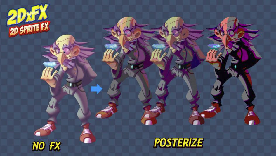
try to use a square?
how can I set it to be the size of the sprite texture?
set what?
the square's size
I'm trying to disable that masking effect the sprite renderer is doing using the texture's alpha so I can develop a more complex shader that covers the whole texture's size
wdym by set the square size to be the size of the sprite texture what texture?
what other texture is there? the bullet texture has a rectangular size
the square has a square size
the texture is not a square
I even thought setting something like queue or rendertype to opaque would work but it doesn't

thats what I'm trying to say so I'm not using a square sprite
You'd need to change the import settings on the Sprite to "Full Rect" rather than Tight if you don't want it to follow the shape of the sprite.
thank you, that worked
It could be a lineRenderer/Spline and a shader on the line/spline mesh.
I'm struggling to get the correct colors in my UI shader graph.
If I have 2 images sitting next to each other, 1 uses the default UI shader, the other is vertex color hooked directly into the color output. There is a mismatch in the colors, why?
Using URP, linear colorspace if that helps
What kind of mismatch? Be aware that Shader Graph doesn't work on UI if the Canvas is set to Screenspace-Overlay mode. Need to use Screenspace-Camera or Worldspace.
@regal stag Aye, it's a ws canvas
The goal is to have the below image producing the same color for both ends. Bottom one uses the default shader, top one is vertex color into color output.
If I try changing the color, it seems that in general the vertex color will end up being slightly darker and higher saturation

grey lines are just wireframe / safe to ignore
Hmm maybe try putting the vertex colour through a Colorspace Conversion node? with RGB/Linear, not sure which order.
I've tried that -> linear to RGB produces results that are slightly closer but definitely not right on
RGB to linear produces something farther away
Hmm well, could try replicating what the UI-Default shader does. It seems to have _Color and _TextureSampleAdd properties that might be affecting the colour. https://github.com/TwoTailsGames/Unity-Built-in-Shaders/blob/master/DefaultResourcesExtra/UI/UI-Default.shader
oh my god
the sprite unlit graph's output is affected by vertex colors from outside of the shader
or at least from outside of the graph
e.g. leave color node to default with nothing plugged into it. Assign mat to image, change the color of the image on the component and it'll affect the render
oh well, solved, thanks @regal stag
This is so confusing. Like hey we will multiply the colors from the component for you but we're not going to take care of the multiplying the texture's alpha from the same component
Ah yeah, sprite graphs automatically tint using the vertex colour.
Hello, I'm using a procedural skybox which dynamicaly moves a texture in the sky. Now I would like to use the "scene color node" in a shader graph to add a refraction effect on a cube in the scene. My problem is that the "scene color node" gives me the colors of the sky at the first frame, it is not updated when I the procedural skybox moves its texture. So I have a "moving" sky while the refraction on the cube doesn't move at all. Is it normal ? How to solve this problem ? I'm in URP.
Is the shader using the Scene Color node set to Transparent surface mode under Graph Settings?
Yes
That's odd then. The scene colour node should just be the camera view before rendering transparents, if the skybox is animated the refraction should be too.
@regal stag is there a way to check the content of the camera view before rendering transparent ? I don't now how to debug this problem.
The Frame Debugger window should show you
Either step through it or find the refracted object/cube and check it's texture inputs for _CameraOpaqueTexture
@regal stag, ok thanks, I never used the Frame Debugger window. I'll try 🙂
@regal stag, from the frame debugger, I can see:
My cube (in fact this is a plane) is probably one of the 3 "SRP Batch", But I don't have any _CameraOpaqueTexture or any info

Sounds like a bug... I have no info available at the right panel 😦
I have the same problem than this guy: https://answers.unity.com/questions/1937807/frame-debugger-has-no-info-on-draw-mesh-calls.html
Unity is the ultimate game development platform. Use Unity to build high-quality 3D and 2D games, deploy them across mobile, desktop, VR/AR, consoles or the Web, and connect with loyal and enthusiastic players and customers.
I can't seem to get Scene Color to work in Unity's default render pipeline, I'm using shader graph. I usually have no issues with this in URP and HDRP
Edit: I just switched to URP, screw this

Hello eveyrone, I have a basic Slash Mesh and wanted to create a Shader for it.
I have this parameter to control what angle of a slash I want by setting Alpha on specific parts of UV,
but for some reason Unity is Offseting it weirdly as you can see from the video. The Angle is not straight at it should be and UVs seems to be correctly unwrapped.


