#archived-shaders
1 messages · Page 45 of 1
did I set up your fix wrong?

Hm no, that looks okay
That's the inside of the 'Mesh Depth' node pictured above
Ah I see
the full flow ignoring other stuff unrelated going on bellow

Those bias are applied during the ShadowCaster pass, which is used when rendering objects into the shadowmap. So there isn't a way around it that I can think of, apart from the offset we're doing.
Provided that offset is larger than the normal bias it should look fine though?
doing a gif capture of what different values do
changing the bias to be any larger than 0.05 produces jank

I am going to try to frame debugger step by step a scene with just this one mesh and nothing else in it
nuts, debugger didnt show anything useful

the first time you can see the mesh the problem is already there


the output of Mesh Depth with and without Normal Bias from the URP renderer
maybe the problem is that the bias we're applying isnt biasing it in the same direction that the normal bias that unity is using does 🤔

adding bias healed SOME of the jank but not all
mm, there is no ComputeShader.SetUInt, how do you set unsigned ints?
ill experiment with different spaces, you can see here that adding unity's bias and adding your bias don't move it in the same directions 

Seems like Unity applies the bias using this. Maybe try the same thing but with bias values negated/*-1? Idk
Good find, will try. I tried the 4 spaces on the node but none of them were a magic fix (world, object, tangent, view)

this is me trying to fill in all the values, still getting pink atm only half done
hm it seems pissed about the names but wont let me change the names
Gotta sleep so good luck. If you post any more messages may want to move into the #1099329453106143242 thread or make another so you don't fill up the chat here
Does Compute Shader has a PI constant?
no
Oh
can somebody explain the difference between the scene depth sampling modes. I've looked at the api and don't really understand them

I always just use a #define
the vertecies the material is assigned to
I’m not really sure but my guess is that “Eye” is for VR applications (so maybe it gets two values, one for each eye). Linear01 returns the depth value as a linear value where 0 is closest to the camera and 1 is max distance from camera (the camera’s far plane). Raw probably returns the raw depth value, which is not guaranteed to be linear. I’m not sure if you’re familiar with how depth values are stored, but you can read the “Using depth textures” page on the docs for more info. Lmk if you want more detail. (I’m guessing you’ll most likely want to use Linear01)
no eye is not only for vr or each of the two values for each eye😅
eye depth or view depth is the to the cameras perpendicular distance between the near clipping plane of the camera and some position in the scene
Oh true. Well @full loom see the above answer 😁
I don't know if anybody has ever had this specific issue and I don't really know how to explain it, but I have the artifact that always appears from depth based outlines, so I fixed it using a fresnel, but adding fresnel causes it to erase the outlines on objects in front of where the fresnel would normally be applied. Does anyone know any other ways to fix the first artifact that doesn't cause the second?


The first artifact is the black face on the left and the second are the missing parts of the outline by the way
Might be too specific of a case for anyone to help but I appreciate any ideas
hard to say, we don't know how you did your outline, we only know that you used depth to construct it
I'm basically just checking a 3x3 radius around each pixel, and then if the depth increases by a certain threshold, it will draw an outline. The way that I fix the artifact is by removing parts of the outline where the faces of the object they are on are at a steep angle relative to the camera view. This makes it so that the object behind can remove an outline of the object in front if it is steep which causes the second artifact.
it depends...
@full loom
https://alexanderameye.github.io/notes/rendering-outlines/
https://bgolus.medium.com/the-quest-for-very-wide-outlines-ba82ed442cd9

Different techniques for rendering outline effects.

So I have this water shader
yet when im in play mode
it is invisible
URP project
Any ideas?
@full loom I’d also recommend this article I like. It talks about how to solve that specific issue on the left. https://roystan.net/articles/outline-shader/
Learn to write an outline edge detection shader for Unity engine, integrated with the post-processing stack. This effect is especially popular as a compliment to toon shading, or in CAD and architectural rendering.
Is there a property a script could use to check if a material/shader has shadowcasting enabled?
Hi, I am using Shadergraph and URP, for some reason my material always mixes to one solid color when I apply it to my sphere (not the usual sphere but a code-generated one)
Is there any settings or anything I need to change in order to make it work?
P.S.: when I apply that same material to a unity sphere it shows the texture just fine, so it is the generated spheres fault, but no clue why)
The left one is the usual unity sphere, the right one my generated sphere made of 6 meshes

are you sampling your textures using uv's? If so does you generated mesh have uv's? If not, then that is your problem
Voronoi Noise from shadergraph seems to work with UVs, and I am not sure about my code but it probably isnt haha. I will look into it
OMG thanks that helped! Ive got the seems showing now, unless it would be a quick fix (which I guess is not) I wouldnt care about it. Do you maybe know how to fix it?

nice, seams are just something that goes along with uv's, because you can't project a something 3D onto 2D without unwrapping it
but what you can do is use triplanar mapping instead of uv's. Just search it up
This whole post might help, but in particular this section gives some info : https://www.cyanilux.com/tutorials/depth/#modes
If the water shader uses the Scene Depth node, make sure the Depth Texture setting is enabled on the URP Asset. Same goes for Scene Color node and Opaque Texture setting.
I'd also double check the water plane even has a draw call by using the Frame Debugger window too. Perhaps something is culling it? Culling Mask on camera?
Alrighty, I will check it out in a bit
I'm trying to displace the vertex position on the edges only, is this possible?

Hi everyone, I'm working on a project for my masters thesis, and I've got a seemingly simple problem that I just can't solve.
I'm trying to put a texture on a terrain, however, I've got a picture that I want to use as a texture for the entire terrain, and not as paint as the terrain tools provide.
I'm sorry if this is in the wrong channel.
I'll have to test it when I get home, but this method should work for me because they just change the threshold based on angle instead of setting the color to no outline.
Hey there! Question… I am using Unity URP, and I am wondering how to use a roughness map in the metallic map surface input? Can I simply inverse the colors of the roughness map in Photoshop – Or is it more involved? Thank you!
The metallic input takes a mask map, so the roughness/smoothness is in the alpha channel
Thank you, so I can just take the alpha from the roughness map? Or do I also need to invert it first

Awesome thank you!
When your putting your roughness map in, enable import as roughness
Unity uses smoothness which is roughness inverted
Awesome thanks @spring fox
Hello there, I want to start learning compute shaders for processing large data, but I cant seem to find a guide or tutorial that covers my needs; all the things I have seen use a Texture as tutorial and what I need is just pass and retrieve data, specifically I need to output float or int values (I want to do perlin noise calculation in a compute shader) does anyone know any guide for this?
not for perlin noise itself but for processing data different to textures in compute shaders
Not much of a tut but you need to use this https://docs.unity3d.com/ScriptReference/ComputeBuffer.html

I have seen this concept, which indeed is what I need, but my question is about the computeshader itself, tutorials use the default texture rather than process an int or a float and return a result
Hi im creating basic forest but im having some white things problems on shaders/materials
could anyone explain me what could that possible been the cause of this problem / URP

I know it depends of each function. But I can't find any guide which explains how do you determines that.
I only found that 32 and 64 are minimum preferential numbers used by AMD and NVIDIA, so 64 is usually the minimum used. Apart for that, you should always use multiples of that number to avoid wasting threads... but no guide tells you when is good idea have more than that, like 128 or 256.
this should give you all you need to know https://gpuopen.com/learn/optimizing-gpu-occupancy-resource-usage-large-thread-groups/
when to use single thread groups, when to use two thread groups when to use large once and so on
I'm trying to make a scrolling / paralax background for my game. I want to have multiple layers that scroll at different speeds. I'm able to move the uv of my sprite renderer like sprite.material.SetTextureOffset("_MainTex", camera.transform.position * s.damping);
but it seems that unity is slicing up the image into many smaller meshes so it only has to render the non-alpha parts. Is there a way to disable this behavior so that the sprite renderer mesh remains intact?
Here is an image of a star before the image has been scrolled at all, and another when it has scrolled slightly. As you can see, there appears to be an edge of the mesh on which the star is drawn. If I scroll further the star will disappear completely until it appears on a place where there was another star drawn.


I believe this covers what you want https://catlikecoding.com/unity/tutorials/basics/compute-shaders/
A Unity C# Basics tutorial about using a compute shader to make it possible to show a million moving cubes.
I am getting a very unexpected result when trying to use a URP Unlit Shader Graph shader for an Image

Anyone know if you can use triplanar texture sampling but with a randomized rotation for each tile?
this looks like UV coordinates
it looks normal in the scene view, but it shows up like this in the game view
turning off "Cast Shadows" makes it turn a dark reddish color; it's busted either way
neither case seems to care about the actual base color
this might be a gross mis-use of the shader graph 🫠
d'oh! i just needed to change this

Is there an "in range" node?
that tells you if a float is between two other floats
i can just slap together some comparison nodes with an And
but it'd be nice to cut down on the clutter

why is it pink
i followed a tutorial

✅ Get the Project files and Utilities at https://unitycodemonkey.com/video.php?v=IC5JoS0wX0s
🌍 Get my Complete Courses! ✅ https://unitycodemonkey.com/courses
👇
👍 Learn to make awesome games step-by-step from start to finish.
🎮 Get my Steam Games https://unitycodemonkey.com/gamebundle
🔴 RELATED VIDEOS 🔴
3 Ways for a Scope Zoom Effect (Unity Tuto...
Somehow the shader go invisible after restarting Unity 
And there after

Unity version: 2022.2.1f1
Is this a bug or have I forked up something?
Attached inspector for said trail renderer

Ah, confirmed bug.
Of course, what else..
I deleted the meta file and now it works.
If you just connect a Vector4 to a Float port it'll use the red component. You need to use a Split node to obtain the alpha component instead
That's what I had originally.
Even then it bugged out.
This is what I had before

But thanks for the heads-up
It's probably best to patch often especially when not using an LTS editor
That one is quite a few bugfixes behind
Fair enough.
I had to go with this one because UI Toolkit is insanely bad in Unity 2021 and below
I think HLSL is the only way to go (there may be some packages made by others tho). When building to openGL etc. the shader code will be translated to GLSL but I dont think you can code directly using it
darn. I write my shaders in GLSL before porting them to unity manually. Does anyone know of any good real time shader editors in HLSL
(im adverse to the shader graph because it doesn't really work with my workflow)
Oop, it actually seems to be possible but as the site implies, its not recommended https://docs.unity3d.com/Manual/SL-GLSLShaderPrograms.html
Only one that I know of is Rider, may be some others too. Visual studio atleast doesnt co-operate with HLSL well at all
how about an easy way to port GLSL code to HLSL? Even something that automatically converts simple syntax differences (like texture2d to tex2d and vec to float) would be good
is there any way in shader to detect how much of a mesh is in shadow vs how much is in light?
I dont mean x is in shadow and y is in light, I mean a single value summed % of surface area in light
I know in code I could fire raycasts and see if they collide with anything but that sounds really unoptimal
Find and replace feature would be my best bet
my xy use case is when an object with high internal light scatter is partially in light, the parts in shadow get emissive luminated 🤔 like an orange slice or a gummi candi
i do that, but it's quite tedious to do find and replace for every difference
Not in fragment shader no, fragment shader can run math only for the current pixel, it doesnt know anything surrounding it (well, partial derivatives are thing), and even less it can access data from the areas of the mesh that is not rendered by the camera (occluded by other objects/not in view frustum)
nuts, good to know though
Youd need to render some sort of light map for the object and count the pixels on shadows which is not going to be cheap anyway so atleast for me it seems like the factual persentage is not available in any reasonable way but you could probably approximate it in some way
is there any way to solve shadow acne that DOES NOT use normal bias?

I have a shader that completelt breaks if normal bias is above 0
but inversely shadows look bad if normal bias is 0
and I want both
Sounds like you gotta fix that shader then… Somehow URP manages to make the shadows have very minimum acne even when normal bias set to 0. I assume this is for birp in which case im out of clues, normal bias is quite essential for avoiding acne
shader can't be fixed, or if it can, I am not skilled enough to fix it
also normal bias is creating janked up holes in shadows for unknown reasons as well

those same holes are the problem breaking my shader, but the mesh has no holes
googling it seems to have something to do with smoothing groups
Splitted/flat shaded edges rather
Making the shadows render both sides can make most of the edges disappear
right, by smoothing groups I meant by it not being one giant smoothing group, what you said

that did help a little bit

but wasnt a magic bullet
am i going to have to author bespoke normal maps for every single 'low poly' mesh if I dont want the shadows to have seams like this
I guess that rock doesnt have a bottom face in it? (That would help on those gaps)
it does not, you are right I didnt include one since you aren't supposed to ever be able to see under it
Moving it into the ground does hide those lines, I had it floating for no real special reason, though even with 2 sided seams do appear


capping the bottom in 3d modeling software easy to do
two-sided mostly fixes it save for on narrow edges, I can just rotate the mesh so its less noticable but that doesnt feel like a 'sollution' as much a bandaid, plus the sun moves
I guess the 'perfect' sollution is to make it all one smoothing group and then author a normal map from the lowpoly

which requires an UV unwrap thus erasing the benefits of the 'low poly' look
So you want to render it as low poly right?
I would like it to look like the mesh on the right, but to cast shadows as if it were smooth
hrm how hideously unperformant would it be to hide the smooth mesh inside the poly mesh

that would be doubling the geometry for every mesh where I did this, that sounds terrible and not something I should do

smooth mesh set to cast shadow only inside of poly mesh set to not cast shadows at all
this definitely feels like a bad idea

Luckily getting smooth shaded model to render as flat shaded is surprisingly easy with shaders https://hextantstudios.com/unity-flat-low-poly-shader/
That might be just what I am looking for, and doesnt involve terrible double mesh hacks Thanks for the link Ill try this out
Sorry, its 3am here so maybe I should go get some sleep now 😅. Ill be back tomorrow
Is something like this a good parallel reduction function? Not sure about the loop. (Compute Shader)
RWStructuredBuffer<GridAllocationInfo> gridAllocationInfos;
groupshared GridAllocationInfo gridAllocationInfosShared[128];

[numthreads(128, 1, 1)]
void PrepareGridAllocationInfo(uint3 dtId : SV_DispatchThreadID, uint3 gId : SV_GroupID, uint gI : SV_GroupIndex)
{
    int from = dtId.x * 64;
    int to = min((dtId.x + 1) * 64, particlesDataCount);

    GridAllocationInfo info;
    info.Count = 0;
    info.Radius = 0;
    info.Min = positiveInfinite;
    info.Max = negativeInfinite;

    [unroll(64)]
    for (int i = from; i < to; i++)
    {
        ParticleData particleData = particlesData[i];
        if (particleData.Radius == -1)
            continue;

        info.Count++;
        info.Radius = max(info.Radius, particleData.Radius);
        info.Max = max(info.Max, particleData.Position);
        info.Min = min(info.Min, particleData.Position);
    }
    gridAllocationInfosShared[gI] = info;

    GroupMemoryBarrierWithGroupSync();

    SubPrepareGridAllocationInfo(gI, 128);
    SubPrepareGridAllocationInfo(gI, 64);
    SubPrepareGridAllocationInfo(gI, 32);
    SubPrepareGridAllocationInfo(gI, 16);
    SubPrepareGridAllocationInfo(gI, 8);
    SubPrepareGridAllocationInfo(gI, 4);
    SubPrepareGridAllocationInfo(gI, 2);
    SubPrepareGridAllocationInfo(gI, 1);

    if (gI == 0)
    {
        gridAllocationInfos[gId.x] = gridAllocationInfosShared[0];
    }
}

void SubPrepareGridAllocationInfo(uint gI, uint threshold)
{
    if (gI < threshold)
    {
        GridAllocationInfo info = gridAllocationInfosShared[gI];
        GridAllocationInfo other = gridAllocationInfosShared[gI + threshold];
        info.Count += other.Count;
        info.Radius = max(info.Radius, other.Radius);
        info.Max = max(info.Max, other.Max);
        info.Min = min(info.Min, other.Min);
        gridAllocationInfosShared[gI] = info;
    }
    GroupMemoryBarrierWithGroupSync();
}
im beginning to wonder if my render pipeline settings or project settings or shadow settings or some setting buried somewhere is bad and I'm trying to 'fix' it at the wrong place 🤔

getting acne even with normal bias
The resulting buffer, I copy it to the CPU and do the final reduction there
Does anything change when you move the normal bias slider? Could it just be that you are modifying a wrong URP asset? Second thing that I am thinking is that maybe your meshs normals are messed up somehow, atleast it looks like it. Those edges seems very hard for smooth shaded. Any clue why would that be?
Hello, I'm looking to make a mirror room in unity
so basically the character is transparent so it would just mirror the rest of the map
but I got no idea how do I go about making a shader for it in an optimized way
because I'm gonna have hundreds of mirrors going in at the same time
and mirrors can also face eachother too
which is a headache
there's one more thing which is the fact that I'm gonna give the mirrors a water-like effect but I found a tutorial on that on yt so no issues there
What does "the rest of the map" entail? Objects other than the player that are in the room?
yes
mainly just cubes
basically the rooms contain the 3D mesh of the room itself, cubes, the player which has no visible mesh and ofc many mirrors
If you need to distort the reflection, that rules out stencil portals, which is the most efficient way to draw portals. Portal 2 uses that technique, whereas Portal 1 uses textures, which you will need if you want to do distortions.
Mirrors == portals in graphics
ah I see
well actually I was going to use the mirror for a portal
so in the end it is a portal nonetheless
using the stencil portals method would you be able to let's say draw at least 20 of them in the same room (not level)
cuz if so then I might just be going with this and see what I can do
The portals themselves are pretty minimal cost. It's more of a question of what needs to get rendered in the portals. If you have a room with 20 objects and you have one mirror covering a wall of the room, then you need to draw up to 40 objects (some of them may not be visible from both perspectives and can be culled). With every new portal, you have to render the scene again from that perspective.
But for portals facing each other, you have to fake it at some point, because they will be infinitely recursive.
oh I see
You can hear a Portal 2 developer talk about their rendering technique in this talk. He starts with comparing textures vs stencils and then goes through all the problems they had to solve:
https://youtu.be/riijspB9DIQ?t=281

Developers who created the game Portal discuss problems they faced and how they solved them.
This beginner's course teaches the foundations of game development. This video is lecture 11 of CS50's Intro to Game Development from Harvard University.
Check out the full course playlist: https://www.youtube.com/playlist?list=PLWKjhJtqVAbluXJKKbCIb4x...
thank you very much
Hello! Sorry if this is basic, but I haven't been able to find a solution for this. I am currently trying to create a custom render texture with a camera. I have the texture and the camera configured and working but now I want to apply a shader to said render texture. The shader is a simple fog post processing effect. The problem is I have no idea how to make the shader work properly, nor how to apply it. I am a bit lost, I have tried making a Custom Render Texture Shader and applying it using a material but I don't seem to be able to get it to work. How could I do it?
Any idea how this error is possible in this scenario?

This is because the third parameter which you have set to 255 is not the z dimension of a 3D texture. It is the bits assigned for the depth buffer of the texture. To make a 3D RenderTexture, you have to change its dimension to Tex3D and then assign the z dimension through volumeDepth.
Both of these are not in the constructor, so you have to set them after the constructor and before .Create()
not really, no
Yes it's sneaky that it uses a variable name that is easily confused with something else.
I tried following this tutorial (results left) but its weird in a way I dont understand


it looks like its not receiving any shadows or something
is it lit or unlit shader? (should be the first one)
Its lit

the website shows Vertex Color plugged into base color but that doesnt make it look any better


anything obviously wrong in here?
oh I think I found it


I was doing DDX on top and DDY on the bottom
turns out order mattered
working as desired 👍

lets agree to disagree¯_(ツ)_/¯
if the order is different, cross product gives the exact same vector except opposite direction which obiously will mess up the lighting
you can use the right hand rule to figure out the cross product input order although in this case I'm confused myself of why the vertical derivative must go first 🤔
I just realized that I can make the portal as a stencil poral and then use a transparent cube with a water shader in which the portal will reside
that solves one problem
That would mean you would only see distortions on the outer most portals. You would not see any additional distortion on portals rendered inside other portals.
But with enough distortion, you may not be able to tell.
do I have to use a different camera for each portal?
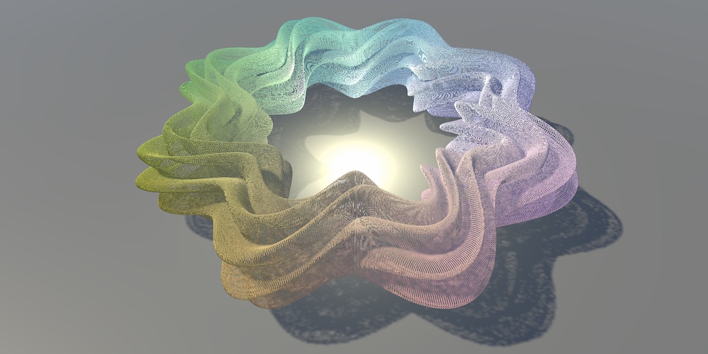
I have been working on making my cloud system less symmetrical, and the main issue I am running into is I can't get my whorly based fBm noise to tile. The whorly noise part tiles, but the moment I add more than 1 octave I get results like the one above. Any idea what the issue might be? I have attached the computer shader I used to generate the noise for context

im trying to make a edge line like this output of the add, lerps with sample texture and goes to base color any helpfull idea ?


what does 'like this' mean?
sorry the like the red drawing, i mean trying to make a linear line at the edges while disolving, but now im blending them wrong
in here im trying to limit blue noise edge

hi ,
im self learning shaders and i was wondering if shaders could send to a regular c# script some data like an array or a list of world position points ?
well it seams like you accomplished pretty much what you wanted the only thing missing is to make it actually transparent instead of white
it is possible with buffers
You can have shaders write to arrays/buffers, but you just have to keep in mind that a shader is executed for each vertex and pixel, so it's not like you can just return one number from a shader.
buffers like float3 ?
well a buffer can contain a float3 but I mean more specifically ComputeBuffers
ohh !
ok then maybe i could just make a condition for to limit that and actually keeps the list on the shader and just read the list value from c# on update and compare it's value , is that is the right way to do it ?
could u give me an example code wise , i'm not sure what u mean , iam still trying wrap my head around all that
But which vertex or pixel do you want to write to the array? Should they all try to overwrite each other? There might be millions of pixels.
fine in c# you can do ```cs
ComputeBuffer buffer = new ComputeBuffer(....);
buffer.SetData(something);
material.SetBuffer(buffer);
buffer.GetData(...);
in hlslRWStructuredBuffer<...> buffer;
buffer = ....;```
that's a good point , maybe one time on a single frame , with some conditions maybe i could limit the number of pixels as well and from those each pixel check if it's position exists on the list and if not they add themselve's to the list , right ?
Could you explain what kind of data you want to get from the shader?
thanks a lot , i have never seen such code before , u have just opened my mind to a new possibility ❤️
nothing on my mind, i just know that we send data to shaders and I wondered if it was 2 ways route and if that was practical, in my example i was wondering if i could notify a c# script about maybe the dots or a simple position on shader? like a terran or a platform maybe.
Moving data from CPU -> GPU is fast, but much slower the other way around. The GetData call can take a while. Still just milliseconds, but when you only have 16.6ms to reach 60 FPS, every bit counts.
So that's why you don't commonly see shaders outputting data other than the color on the screen.
thank you so much for explaning that ❤️ ❤️ , that makes a lot of sense now
yes GPU -> CPU reading can call a pipeline stall, what you could try is to use is AsyncGPUReadback, which overcomes this problem. The catch is that the recieved data will have a few frames of delay, depending on what you want to do this can be problematic or not. But it is something useful
yes i agree, i believe it wont be perfect for all applications but its good to know the capabilities and limitations of shaders.
Well, SetData also not so fast (And SetData specifically introduces additional data copies here and there under the hood). One of ideas behind whole BRG is exactly reducing sending data from CPU to GPU - frequency and amount (not only this of course, but is one of ideas). But yeah GetData is a lot slower. (Well which can be avoidet partially with AsynGPUReadback)
Ah and as a side note instead of SetData you should always use Begin\EndWrite API, it's always faster, even on hardware that doesn't support "direct" GPU memory pointer.
In shadergraph, how do I get access to matrix4x3?
I can't declare them in the editor, and not sure if there is a way to get them in a custom node without something ugly like declaring 3 separate Vector4.
I can send them easily via BatchRendererGroup, but don't see how to read them directly.
There must be a way since "unity_ObjectToWorld" and other root transform properties are matrix4x3.
You can create Matrix4x4 properties in the blackboard. But I don't think SG supports non-square matrices.
Hi everyone
Im stuck in this problem: can't figure out how i can make it possible
so i made shader like in this tutorial: https://youtu.be/5dzGj9k8Qy8?list=LL
and i want make is pixelated. I did pixelated UV and dont know how i can put position node and my pixelization node together.(1pic)
Position node i need because noise is stretched along sprite sheet, because it have animation and i need it
Result i want is on second pic


I'm trying to write a shader however something with the URP is giving me trouble I believe, even following an online tutorial for a super simple shader results in nothing showing up unless I set to the render queue to transparent for some reason (nothing about this shader should be transparent) I'm reaching my wits end with this. Also please do not suggest using shader graph, I have 0 desire or inclination to play with spaghetti.
Shader "Unlit/SLit"
{

    Properties
    {
        [Header(Surface options)] // Creates a text header
        // [MainTexture] and [MainColor] allow Material.mainTexture and Material.color to use the correct properties
        [MainTexture] _ColorMap("Color", 2D) = "white" {}
        [MainColor] _ColorTint("Tint", Color) = (1, 1, 1, 1)
    }

    SubShader
    {
        Tags{"RenderPipeline" = "UniversalPipeline" "RenderType" = "Opaque"}

        Pass
        {
            Name "LightForward"
            Tags{"LightMode" = "UniversalForward"}

            HLSLPROGRAM

            #pragma vertex Vertex
            #pragma fragment Fragment

            #include "SLitLightForwardPass.hlsl"
            ENDHLSL
        }
    }
}
#include "Packages/com.unity.render-pipelines.universal/ShaderLibrary/Lighting.hlsl"

TEXTURE2D(_ColorMap); SAMPLER(sampler_ColorMap);

float4 _ColorMap_ST;
float4 _ColoTint;

struct Data
{
    float3 positionOS : POSITION;
    float2 uv : TEXCOORD0;
};

struct v2f
{
    float4 positionCS : SV_POSITION;
    float2 uv : TEXCOORD0;
};

v2f Vertex(Data input)
{
    v2f output;
    VertexPositionInputs posnInputs = GetVertexPositionInputs(input.positionOS);
    output.positionCS = posnInputs.positionCS;
    output.uv = TRANSFORM_TEX(input.uv, _ColorMap);

    return output;
}

float4 Fragment(v2f input) : SV_TARGET
{
    float2 uv = input.uv;
    // Sample the color map
    float4 colorSample = SAMPLE_TEXTURE2D(_ColorMap, sampler_ColorMap, uv);
    float4 ColorTint = (1, 1, 1, 1);
    return (colorSample * ColorTint);
}


The shader must have DepthOnly (& DepthNormals) passes.
(Technically you can stop it going invisible even without these, by disabling "depth priming" on the URP asset. But then objects still might not appear in the depth texture, so better to have them)
You seem to have the pixellated result, so I'm not sure what the problem is?
Is it possible to replicate how unity blends vertex colors in shader graph?
There's a Vertex Color node. SG already interpolates the values for you if you use it in the fragment stage, is that what you mean?
yes, I'd like to replicate how SG calculates the vertex colors
except I select the colors at each vertex myself
I'm aware that I can change the vertex colors of a mesh but when multiple triangles share a vertex it yields results that I don't want
I could separate the vertices when creating the mesh but then I'd end up with more vertices
Yes, this is what you need to do. It can't be done in the shader
Unfortunate
Hello Folks! Can somebody tell me what this means? What is UNITY_SHOULD_SAMPLE_SH?

Anyone got any hot tips for why this is not working?

I figured this was a way to get multiply blended decals in urp but I guess not ?
"SH" probably stands for shadows..? Not sure. Looking at other places where that define is used would provide a better answer.
Either your texture is all opaque or the shader/material/renderer ignores the alpha channel for some reason. Hard to say anything without knowing the context.
How can I set data to a ComputeBuffer in a background thread?
It takes a lot of ms to do it in the main thread 🥺
It's stretched, because the main texture in shader graph, for example, is single texture. But in game a whole animation. In tutorial on 9:25 he shows the example and why he added position node. So final result for me is not pixelated
How its looks actually:

I am confused, you usually set the buffers in c#?... or what do you mean exactly?
You use this https://docs.unity3d.com/2020.1/Documentation/ScriptReference/ComputeBuffer.BeginWrite.html pass the native array to a job, do your work and then complete the job in late update and call EndWrite
nvm, i finally figured out how to make it.
Hello! I'm working on a script that overrides the textures of a specific terrain layer at runtime. While the diffuse and normals are stored in their own Texture2DArray's, the Height/Smoothness/AO are stored within the green channel of the diffuse/normal textures (not sure how that works). However, those textures can also be accessed through a struct that's found within the subshader of the shader I'm using for this (MicroSplat). Is there a way to access the struct through code to override these textures?
My script:
    {
        StartCoroutine(ReplaceTexture());
    }

    IEnumerator ReplaceTexture()
    {

        yield return new WaitForSeconds(1);

        Debug.Log("10 seconds waited");

        myTerrain.materialType = Terrain.MaterialType.Custom;

        Material terrainMat = myTerrain.materialTemplate;
        Shader shader = terrainMat.shader;

        Texture2DArray diffuseArray = terrainMat.GetTexture("_Diffuse") as Texture2DArray;
        Texture2DArray normalArray = terrainMat.GetTexture("_NormalSAO") as Texture2DArray;

        Debug.Log("Array depths:" + diffuseArray.depth + " " + normalArray.depth);

        Texture2DArray newDifArray = new Texture2DArray(diffuseArray.width, diffuseArray.height, diffuseArray.depth, TextureFormat.DXT1, 11, false);
        Texture2DArray newNormArray = new Texture2DArray(normalArray.width, normalArray.height, normalArray.depth, TextureFormat.DXT5, 11, false);

        for (int x = 0; x < diffuseArray.depth; x++)
        {
            for (int y = 0; y < diffuseArray.mipmapCount; y++)
            {
                if (x == 1)
                {
                    Graphics.CopyTexture(diffuse, 0, y, newDifArray, x, y);
                    Graphics.CopyTexture(normal, 0, y, newNormArray, x, y);
                    Debug.Log("Custom layer replaced");
                }
                else
                {
                    Graphics.CopyTexture(diffuseArray, x, y, newDifArray, x, y);
                    Graphics.CopyTexture(normalArray, x, y, newNormArray, x, y);

                    Debug.Log("Texture copied");
                }
            }
        }

        terrainMat.SetTexture("_Diffuse", diffuseArray);
        terrainMat.SetTexture("_NormalSAO", newNormArray);

        Debug.Log("Textures set");
    }

}```Can we convert custom shader into urp lit shader
Hey, any idea how to create a shader which duplicates the rendering of a mesh ? (I want to simulate a crowd with any a few animators& skinned meshes).
just dublicate the actuall people
Or do gpu instancing if it is a lot of people and they don't need to exist on the cpu
I would like to save the calculation of the animators and skinned mesh renderer (they are they performance killers)
that didn't make things clearer for me to understand
you want to use a shader to save animation data??? why? purpose??
What do you mean by calculation of the animators? Like a baked mesh per frame? (Otherwise as far as I can tell I agree that gpu instancing is the solution). You could also limit bone influences from 4 to 2 or 1 per vertex to increase performance slightly. Also these pages might help: https://github.com/chengkehan/GPUSkinning and https://forum.unity.com/threads/experiments-with-instancing-and-other-methods-to-render-massive-numbers-of-skinned-meshes.447749/

GitHub
Contribute to chengkehan/GPUSkinning development by creating an account on GitHub.

Unity Forum
Hi,
For the past week I've been contemplating and experimenting with methods to render massive numbers of skinned meshes in Unity. Initially I was...
Thanks, I'll take a look
I can only find APIs to set buffers in the main C# thread
But EndWrite must be called on the main thread an it takes like 1.4 ms, run that several times per frame and it takes considerable time
I guess there is no other option, right?
are you setting the buffer multiple times?(every frame)
Once per physics update, which means several times per frame
why
Because I must copy the position and velocity of my entities each time they are updated.
I'm trying to make a Smoother Particles Hydrodynamics which can interact with rigidbodies.
So each particle is an entity with LocalTransform, PhysicsMass, PhysicsVelocity, PhysicsCollider (Spherical).
Which means, each time position or velocity updates in Unity side, I must send that info to the GPU, compute particle/particle collision, and send it back to Unity.
@midnight wren End write taking 1.4ms is strange
I use it on a 100mb compute buffer that stores rendering info and haven’t seen a hitch
Ah but I see you are doing it even multiple times per frame
Then I can recommend the command buffer approach from here https://github.com/Unity-Technologies/Graphics/blob/graphics/gpudriven/com.unity.render-pipelines.core/Runtime/BatchRenderer/BRGTransformUpdater.cs. Or look into the sparse uploader from entities graphics https://github.com/needle-mirror/com.unity.entities.graphics/blob/master/Unity.Entities.Graphics/SparseUploader.cs

GitHub
[Mirrored from UPM, not affiliated with Unity Technologies.] 📦 The Entities Graphics package provides systems and components for drawing meshes using DOTS, including support for instanced mesh rend...
How do I obtain Texel Size for a sprite in an atlas?
Hi
I have a compute shader that sets a bunch of points into a scene, but I would like it so that if there's one that doesn't pass a certain criteria, a single bool is passed back to the cpu telling me that at least one is not passing, how could I do that?
you can do that with computebuffers for example
I was hoping to have another option, but otherwise I will continue with compute buffers
I have a shader that needs to read from scene depth/color. Is there any benefit to making it an opaque shader and changing the render queue to transparents, or is it the same as if it was transparent?
Assuming shader graph, the "Blend mode" would be off if using Opaque surface mode. That might make it slightly cheaper but I doubt it'll be a huge difference really.
It would also write to the depth buffer but you can disable that in the Graph Settings (if you're in 2021.2+ I think?)
@regal stag Ah, yeah I can see it 2021.3 -- super, thank you for the runthrough
Like {TextureName}_TexelSize ???
There's a node in shader graph for that too.
yea but my textures are in atlases so it doesnt give me the correct texel size or something. Effectively when we moved them to Atlases the shader stopped working properly
Well then you'd have to adjust the math to divide by # of tiles x and # tiles Y. But atlas use also needs to compute the starting offsets.
All depends on how you use it. I mean, it gives the right value for the atlas as a whole, but not for a tile.
And you'll probably have to pass that info in somehow.
What's the shader graph equivalent to blender's generated input coordinates? It seems like it's still using badly unwrapped UVs still
im noob, in tactics games, is the grid showing movement range a shader?
Hey guys, Im new on unity, how I can do to make a shadow to my sprite, Idk how I can proceed

Hello! I'm struggling with shader graph and was hoping someone could help. I have a tiling and offset node, and a sample texture 2d node. I would like to add padding or spacing between each tiling of the image. Any advice?
The easiest and cheapest way would be manually editing the texture to have that padding.
But you can also do it with maths, (see image).
One problem here though, is if the texture has mipmaps enabled you'll get pixellated seams. Either disable mipmaps or swap it out for a Custom Function so you can use SAMPLE_TEXTURE2D_GRAD(Texture, Texture.samplerstate, TiledUV, ddx(UV), ddy(UV)); where TiledUV is the result of the group, and UV is the result before the Fraction node.
https://www.cyanilux.com/faq/#sg-pixellated-seams

Idk why the noise isn't 3D using world space

Thank you so much! Serious life saver.
been trying to do this for hours 😅
Shader graph doesn't have 3D noise functions built-in. There are some custom function/subgraph libraries that add some though.
https://github.com/JimmyCushnie/Noisy-Nodes
https://github.com/RemyUnity/sg-node-library
An alternative is sampling a tileable noise Texture2D using the Triplanar node, which samples the texture 3 times from each world space axis and blends based on normal vector.
I was trying to use a triplanar node but didn't know how to work it out actually
This is my setup

I am trying to simulate backscatter and to that effect I need to mask out a specific range of values (only the backscatter)
Picture 1 you can see that range's mask working well. there is some falloff onto an adjacent object but that's acceptable, they both use the same material so there's no way to fully mask that one's object but not the other's
The problem


the problem is the method I got this mask creates this white band and I can't figure out how to get the mask I need without this band forming

means of generating the data


everything pure white needs to be masked out , but without generating that white line
and anything that is not pure white should not be masked out at all
the problem is probably that im using a sine to get the range I want

but i am not sure how to get the range i want without it
is there a node or a formula that will isolate a specific band of values
for example this method to isolate a specific band of values

still generates 'the line'

yeah every combination of values creates this line

and I need it to not
somehow masked it from just the front, but how to also do the back

it might be impossible because the value range I want to mask out is the exact same values on both objects, and there is no data available to me that only one of these two instances of that material shares

how do I make screen space reflections in URP shader graph
so I don't have to use reflection probes
yeah i think im just going to abandon this entire attempt, its not giving me the results i need
time to start from scratch again for the 100th time 😿
oof
or reflections in general
but like accurate
What's this funny effect called so I can google it, and how can I get rid of it in my CRT shader? I'm really wondering about the funny lines. They seem to result whenever I have something that's pixelated (this shader or otherwise)
I'm wondering if I should like blur / feather the output or something to try and get rid of it


In mathematics, physics, and art, moiré patterns (UK: MWAR-ay, US: mwar-AY, French: [mwaʁe] (listen)) or moiré fringes are large-scale interference patterns that can be produced when a partially opaque ruled pattern with transparent gaps is overlaid on another similar pattern. For the moiré interference pattern to appear, the two patterns must...
It's Moiré as Bugbeeb said, but in your case it happens because you're under sampling the subpixel pattern. To fix it in my screen shader I just fade the subpixel pattern out with mipmaps so it scales nicely with any resolution.
Does anyone know what happened? i just installed urp and now when i bake lighting its all weird. help

Whenever i bake something it turns pink... maybe a light?

@dark garden Check scene debug views for texel invalidity and lightmap UV overlap after baking and continue the topic in #archived-lighting
nvm im using post processing
Is there a way for a script to tell if a shader/material has shadow casting enabled?
Shadow casting is done in the ShadowCaster pass in a shader. I suppose you could check for that pass type on the shader:
https://docs.unity3d.com/ScriptReference/Rendering.PassType.html
To access the name of a Pass from C# scripts
, you can use APIs such as Material.FindPass, Material.GetPassName, or ShaderData.Pass.Name.

Note: Material.GetShaderPassEnabled and Material.SetShaderPassEnabled do not reference Passes by name; instead, they reference Passes using the value of the LightMode tag.```
^ from https://docs.unity3d.com/Manual/SL-Name.htmlThanks, I will try with this then.
Hi, is it possible in shader graph to feed generated RGBA heightmap to parallax node? It needs Texture2D input so i'm kind of lost.
Can copy the code for the Parallax Mapping node but swap the texture sample out (line 41 in ParallaxMapping.hlsl)
https://docs.unity3d.com/Packages/com.unity.shadergraph@10.2/manual/Parallax-Mapping-Node.html
https://github.com/Unity-Technologies/Graphics/blob/master/Packages/com.unity.render-pipelines.core/ShaderLibrary/ParallaxMapping.hlsl
Try something like this in a Custom Function node
Out = UV + ParallaxOffset1Step(Height, Amplitude * 0.01, TangentSpaceViewDirection);
Could also replicate it in nodes. See ParallaxMapping.hlsl for what the ParallaxOffset1Step function is doing.
Hello! I have a question about filtering/bluring textures.
In my top down tile based game every tile has a light level.
I want to blend light levels smoothly, but I don't know how.
1st image is raw light texture.
2nd image is light texture with biliniear filtering.
But as you can see blinear filtering is not enough, it looks werid.
I have tried the bicubic filtering (through the shader), but it does not look much better than bilinear.
Please help me to find the way to make smooth transition between light levels!


Is it an option to change how the raw light texture is generated? It looks like you're generating it with a limited set of shades, fewer than 8-bit/256 shades.
Yes, it's possible I guess. Will it affect the result?
I think so.
But I guess it will make the light circle either really big or with hard edges between light circle edge and complete darkness
If I got it correct
I don't see why that would happen. The problem here is not the resolution, but the limited color palette. In a gradient, it doesn't ever make sense for two pixels next to each other to be the same shade, unless your resolution is greater than the number of shades you can use.
Ah. Here is only 1 color - black. But alpha channel drops every step to the darkness.
So the light texture is rendered on top of the world. It's completely black, only alpha values change
Do you know what texture format you are using? Is it compressed? Some texture formats and many compression methods use fewer bits for alpha, which can lead to this sort of issue.

Did you override any texture import settings or just leave it default?
I don't think it's compressed.
All imported textures are compressed unless you specify otherwise.
Also, PNG is compressed already, but Unity compressed on top of that.

I have it like that
Should I try another format for that texture?
I would recommend against using the alpha channel for this. Instead, I would use RGB. White pixels can be the same as 100% alpha and black pixels the same as 0% alpha.
With additive transparency/blending. Which is more accurate to how light works anyway.
Many shaders that support transparency will also have the option to use Additive blending, but otherwise you need to make a shader with additive blending.
In Shader Graph, it should look something like this, but it's probably outdated because they're always updating the UI

no
Expensive?
Expensive to do at runtime, and unnecessary since the root problem can be solved.
So you think I should use bilinear filtering + additive blending instead of alpha blending?
To combine the world and light texture
And avoid using alpha for the light texture
And that could heal the artifcats?
Well, there is something wrong with your texture. I opened it in Photoshop and put a green background underneath it to see the transparency. Here's how it compares with a radial gradient:

This could be caused by the PNG compression when you exported the texture.
Yes, really looks weird, haha
Compression algorithms often don't put as much priority on alpha as they do for RGB. So using RGB instead of alpha should be more resilient against compression, but you could also continue using alpha and be more careful about what compression you use.

No problem. Actually, multiplicative blending makes more sense here, since your texture is storing darkness instead of lightness.
Yes, thanks!
But also I calculate light levels on CPU
And I need to somehow create such light textures on the fly
I mean light spread on tiles is calculated on cpu
And I want to convert light level on cpu to pixel darkness on the texture
How complicated is the light spread going to be? More complicated than just a smooth radial gradient from points of light?
Like in minecarft but simpler, because it's 2d only.
Light flows from the sources and loses levels in process.
So light loses levels when it avoids obstacles
Example in 3d

Light spread is calculated on cpu
Well, you won't have to worry about compression if you're generating the texture at runtime, but I think moving to RGB was still a good move because now you can do colored lights properly.
It's interesting how many light levels should I use to get the result like on the left part of the picture
And not on the second part 🙂
Well, most screens are only capable of displaying 256 different light levels (unless it's HDR) and it just so happens that the smallest texture formats supported by GPUs, and by extension Unity, are 8-bit, meaning 256 different levels.
So while you could artificially choose a number below 256, you'd be forced to use textures that are capable of storing at least 256 shades.
Thank you! I was looking in a completely wrong direction to solve that problem
Hi! I'm learning unity for VRChat and I'm wondering if anybody knows a method or shader that makes the 2D object looks like the same in every angle of sight.
I can't find any information through my googling 😦
I do not quite know what you want exactly....
Sounds like a "billboard" shader
i want to learn more about shaders/ shadergraph, are there any good tutorial series you guys recommend?
also, ive found ben clowards tutorial series which looked interesting. but its for unreal. does that translate to unity?
At a glance is there an obvious reason why this shader is affected by scene viewport size?


so for example, this 2D avatar doesn't look like a paper by looking at the side. The front image faces to the viewer at any angle.

What Shader Graph template has "MeshDepth" as output? What specifically is it expecting? Depth can come in various forms: eye depth, linear depth.
mesh depth is my name for the subgraph shown in the image
And are you just displaying the MeshDepth value in the GIF?
Yes that node's output is what is shown there and nothing else
it isn't just for unreal he does it in both unity and unreal but yes core things translate to unity pretty well actually
this is the custom function being invoked in meshdepth which I assume is the source of the problem
Yes I doubt that anything else is directly related to that
What depth are you trying to calculate? Why does it require calculating soft shadows?
thanks, guess ill start there then
Mesh depth from its light side to shadow side
as in a single float that says 'this much thick'
for Transmission
Can you think of other ways to calculate mesh depth from the point where light hits its surface to the fragment being calculated at render?
ah yeah, 5 mins into the first video he says it will be applicable for both unity and unreal 😛
and its not about depth from eye to mesh through mesh, its depth from Main Light to mesh to beyond
Your approach makes sense for that. Do you know if you have screen space shadows enabled?
I can't think of anything else that would be affected by viewport size in your shader.
How would I know/check? I do have SSAO on (I think let me check)
It seems to be an optional renderer feature in URP
https://docs.unity3d.com/Packages/com.unity.render-pipelines.universal@13.1/manual/renderer-feature-screen-space-shadows.html
SSAO was not enabled, I must have turned it off while debugging other things. Checking that now
Hm I think I might not have that feature at all due to being on 2020.3
let me get you a screenshot of what I see, I might be blind thats also likely

One thing you could check is if you notice the shadow map changing at all at different viewport sizes, in the Frame Debugger for example. I don't know enough about URP shadow map rendering to know if there is any connection there. I suppose it might mess with the cascades, sort of like mip mapping at different screen resolutions.
Hi, I don't know if someone can help me but i'll try :)
So i followed this tutorial https://www.youtube.com/watch?v=RMt6DcaMxcE&t=128s to add post process outlines to my game. Now i'd like the line to be "wiggly" so that it looks kinda like the line is drawn by hand. I know i may have to add perlin noise to the graph, but i have no idea where to add it :(
(If you can't see the graph properly, it is litteraly the one from the video)
Can someone help ?


I am not sure where to find the shadow map in the debugger

Unity Forum
When I was learning this SRP tutorial with Unity2019, the rendered shadow map was not displayed correctly on the frame debugger panel. I don't know the...
google search says its bugged and never fixed?
fiddling with the debugger options makes no difference in the appearance

I plugged an override material into the URP renderer to render everything as the shadow texture
you can see clearly at the edge between cascades it does something jank 🤔
i think maybe the cascades are happening in a sphere around the view point? meaning they change at the edges before anything else maybe?
or maybe my copy/version/thing of the shadow texture itself is the problem?
meant to reply to your post with the above
not junk but a transition from one size to another, making the transition less distant from each other can make it a bit less noticeable, or you can make a soft transition yourself, which is a bit of hackle and havent found any info online for one yet
you can test if its transition to just change it while debugging the effect, the cascades should be in URP asset settings
the method being used to get that data

I will try scrubbing them instead of scrubbing the camera

should the edges be that hard?
soft shadows are on
soft shadows only mean that you sample shadows multiple times at one point but only on XY axis, the depth Z axis stays the same, so it wont smooth the transition between two cascades.
hmm, do you have any suggestions on what I could do to to make it less noticeable? You mentioned some kind of a hackle?
I have read that blur methods are generally slow to do at runtime, I don't know if there is some form of blur I could apply that is dead simple, an ugly result is probably still good enough
putting the first splits way closer, so they dont do big texel size jumps, it can hide itself in a scene then
Closer where? As in bunch them together?
yea like 5/10/20 o smth
hmm all it seems to do is change 'when' the jank transition occurs, there's no perfect set of values because the camera /object can move and when it hits the cascade point, jank happens
yeah currently there is no clean solution done I can see :/


Hmmm....
OK, I'll bite (Byte)...
Because you're using a post processing screen pass, you can't change the current pixel's location. But you CAN change where you sample from in the opaque, depth and possibly depth-normals textures. So what you'd do is to sample a bit left/right/up/down based on some offset selected by noise. And you'd want that consistent for all sampling that you're combining so you don't get diverging lines for each sample type. By varying that noise over time somehow, things would "wiggle" where you draw the line color. I suppose you'd want to be careful not to wiggle where there's no line.
@meager pelican Ok, I'm so sorry, i'm kinda a newbie on unity 🥲 So this is what i have to modify, the subgraph ? The way i am sampling is here right ?


how does anyone even use unity urp shadow cascades
the more I poke and prod to try to make it look even remotely usable, it just gets worse and worse
and now im at the point where it looks like complete dogshit and I dont know how to disentangle myself from how compeltely uselessly broken this is
shadow resolution was set to 256
as usual the problem was between monitor and chair
per that video, the sampling is in the custom node code....
im new to unity so excuse me, when i drag my skybox in i cant see it being there, what do i do?
Badly
you guys know why HDRP looks so much better than BRP? I'm thinking it's the tone mapping more than the shader light math
Its the shader light math
hey all, sorry for really newbie questions but i am using cyanilux's toon shader. i'm wondering where in the shadergraph would i be able to make an adjustment to make the overall shadows brighter, including the cast shadows? very unfamiliar with shader graph and unity in general. hoping that i can just make all shadows lighter and not just having cast shadows and form shadows multiplying over each other (my attempt did this.) 

You need to edit your ramp texture to change how your shadows looks. You can make it lighter on the left. It should look like something like that (see the minuscule image at the bottom lol). The more diffferent color you add, the more "steps" you will have on your shadows, and the lighter they are, the lighter your shadows will be
i did try that, and the cast shadows ended up looking like this:

what are the dimensions on your img ? Can you link me to the tutorial you used ?
so i thought maybe there is a spot in the graph that would adjust ALL the shadows to be lighter?  i'm terrible at reading this.
oh the dimensions on the ramp texture? it's 256x32. also i used the shader straight from this link:

GitHub
Some custom lighting functions/sub-graphs for Shader Graph, Universal Render Pipeline - GitHub - Cyanilux/URP_ShaderGraphCustomLighting: Some custom lighting functions/sub-graphs for Shader Graph, ...
If your ramp texture has 3 steps, why does your on scene object has 4 ?
i was assuming maybe the cast shadow is multiplying over the top of the form shadows and making it look like a 4th step in "combine ramp with shadows" but it's also being used for a culling mask (i don't know what this does.) i tried putting an add node and just testing some stuff there, but the cast shadows were still multiplying on top
Ahah sorry I'm not that good either, still a newbie , hopefully more experienced person will answer 😅
Personally I know that when I wanted to change the colour of the shadows and add more steps, I just modified the ramp texture
I personally used this tutorial https://youtu.be/RC91uxRTId8
✔️ Works in 2020.1 ➕ 2020.2 ➕ 2020.3 🩹 For 2020.2 and .3:
► When you create a shader graph, set the material setting to "Unlit"
► The gear menu on Custom Function nodes is now in the graph inspector
► Editing properties must be done in the graph inspector instead of the blackboard
► In Lighting.hlsl, change the line "if SHADERGRAPH_PREVIEW" to "...
thank you i will look at that too, i did try another tutorial by him that the code was just not working in this version of unity i think? or else user error, wouldn't really be surprised. 😭
yeah I did have to tweak some things and change some part of the code for it to work for my version, but if you look in the comments and the video description, pretty much all the changes that are needed are explained here
well thanks for taking a look, i will try to poke at this a bit more since i like how the rest of this shader looks a lot before i give up on it. appreciate the link a lot!
You should be able to make the shadowed areas brighter by changing the ambient/environmental lighting in the Lighting tab. Though that will affect all objects.
If you want to change it for just this shader, changing the value in the Float node in that "Combine Ramp with Shadows" group, should do it iirc.
Omg thank you so much, changing the value works perfectly. I wasn't sure what that did so I was afraid to mess with it. Also I love your shader, thank you for your sharing your hard work 
just started learning about shaders, why is my preview not updating to green?

Save the asset
didnt work, i was messing with a vector 2 node connected to the base color earlier and then i did see the preview update live
i deleted that node and just changed the box next to the base color and now it doesnt work
Is it just the preview ? Is your material green ? If so then I think it is just unity editor that need to be restarted
yeah just the preview, the shader isnt connected to anything yet
does it need to be connected to a material first?
ill try restarting aswell
You don't need to connect it to anything rn, it'll work just fine once you do
If you really want to see the preview, try to connect the base color to a color node
thanks, restarting seems to have fixed it
Perfect 👍
Just so you know the main preview sometimes doesn't update well until you connect new nodes to it but it doesn't mean your material (if connected to a material) hasn't updated it's just the preview that isn't working properly when nothing is connected
thanks, ill keep that in mind
@meager pelican
Ah yes sorry I lost track 😅
So I need to modify the hlsl file that is sampling where to put the line ?
And so how to do that ? If I understood properly, I need to add a Noise float parameter to both ColorSobel and DepthSobel and then add that to where i sample (i don't know how to add the noise to the sampling :/ ) or generate the noise directly in the hlsl (but i don't know how to do that :/). And inside the shadergraph plug in the noise to the custom function and also make it so that the noise texture moves according to time ? And use that noise to offset the sampling points ?
I can get around on how to do the noise (even if all help is appreciated ahah)
But I have no idea how to offset the sampling points using the noise :/
(If anyone also has an answer, your help is greatly appreciated ahah :)
i got another shader related question
im also working on a procedurally generated terrain, but im not happy with the uv coords ive set there. is it possible to overwrite those uv coords with a shader based on world position?
ive seen some videos where the shader seems to correct uv values based on world position or other conditions but i got no clue how it works under the hood yet, basically i want to know if i have to fix the uv coords on the mesh first to get something like that to work, or the shader will just dictate over the mesh and i dont have to bother fixing them now
I am still a newbie so I'm not sure, but I think if you do a shader it'll overwrite your mesh uv.
You can look up some tutorials, and you can even procedurally generate terrain using shaders
https://youtu.be/2AV1tb7_sm4
The first part - https://youtu.be/q4rDPH7J3zw
I really hope my awful explanations were enough for you to learn something useful!
My twitter - https://twitter.com/TMixer17
i just started with a tutorial series on youtube from ben cloward. ill look into more specific stuff once im more familiar with the tools
It's up to you, that's you programming.
I'd sample the noise (whatever one you use) at the same UV offset you're sampling the other textures at, plus some wiggle offset to "distort" it, You may just want to pass that in as uniform value, but maybe not. Up to you.
That result gives you an offset in both X and Y.
You can scale that too by some passed-in value.
And THAT end result, the offset and the original UV added, is what you use to sample the depth texture and the color textures. These offsets are likely to be pretty small float values, since the entire UV range is 0-1.
Basically what you're generating is a wiggle-offset over time.
I guess another way to say it is to...wiggle the distortion/noise sampling, and use that result to offset the line sampling.
In the end, all you're doing is modifying the UV sample location a tiny bit with some maths that vary over time.
You'll have to dig in, as I'm not set to write it or demo it for you.
Ok, thanks a lot for your help, I'll do my best to split everything you said in little parts to do it step by step 🥲
Yo, is it possible to render both low quality and high quality things in the same game view? Basically, I have like an overlay that covers the screen. It displays by having a certain script on the main camera which controls a shader that creates this overlay. I want that overlay to be high quality. But then I also have the game itself, and I want that to be really low quality. Is there any way to achieve this?
Currently I have 2 cameras with one having a low quality render texture, but they only work individually, not together.
Thanks.
Idk if that makes sense lol
no it doesn't at least I do not know what you mean. Because what I am understanding is that you want a high quality overlay but not a low quality one and you want a low quality one but not a high quality one everything everywhere all at once or something idk. I don't get it
Blit the lower quality render texture to the main camera, before rendering the overlay
okay ill try to be more clear, im really bad at explaining things lol
Basically imagine you are looking at your monitor and are playing a low res game. Your monitor is high quality because ofc it is, its in real life, but the game is low quality because its on your screen.
In my case, the shader is kinda like the look of the monitor, with the edges and overlay and stuff
Idk if that makes more sense lol
Hmm okay, a little confused tho, mind explaining further? Thanks
What pipeline are you using
urp
What Unity version?
2020.3.21f1
Should be able to use this - https://github.com/Cyanilux/URP_BlitRenderFeature
Create a second Forward/Universal Renderer asset and add the feature to it. Add the renderer asset to the list on the URP Asset. Set that Renderer field on the Main Camera.
On the feature, use source as RenderTextureObject, drag the low res Render Texture asset used by the camera into that. Will also need to create a shader/material that just samples _MainTex and outputs it. The Unlit Shader template might work, or create an Unlit Graph.
Okay thanks, I'll try that soon and let you know if it works
Hey, I have a question about Compute Shaders. Should I post it here or in #archived-code-advanced ?
Alright xp
I have an issue with Compute Shader IDs acting weird, or rather me just not properly understanding them.
I made a mesher (Dual Contouring) for my voxel engine and I'm now trying to program it into a Compute Shader for massive performance gains.
Here's the plan:
- Construct chunks one after another on the CPU.
- For each Chunk one after the other: Dispatch the compute shader to calculate the vertices and other relevant information for each voxel on a chunk, store them in a buffer, access that buffer on the CPU again.
- Format the data from a raw one-dimensional array to a nice list of structs.
- Finalise the algorithm by winding together triangles, creating the vertex array and forming it into a mesh.
It's all done now, but, of course, it doesn't work. I've been debugging it line by line, fixing various issues, and it's time to test if the algorithm can even properly assign vertices, nevermind the actual computation for them. So, in the shader, just to see if the connection between shader and C# script works properly, I wrote this, leaving what I've had behind a return line:

It takes the unsigned integer id and converts it to the id I'm using, which is basically just shifted so that 0, 0, 0 is the center of the chunk. (this is idSigned)
Then, in the vertices buffer, which is a RWStructuredBuffer of float3x2s, it writes the computed vertex (for now just (0, 0, 0)) and after that the id of the voxel in the chunk
In the C# script, this is the method the voxel engine goes into when executing the meshing algorithm:

Everything other than the two circled bits are irrelevant.
We declare the two buffers that will store our results, and enter the method preparing and executing the compute. Afterwards, I want to simply see in visualisation through cubes what the actual voxel IDs are that it computes. Voxel IDs are really just identifiers for each voxel in a Chunk.

This is the struct in which we get the most important info; the vertex of a voxel, and the voxel's unique identifier.
Now, in executeCompute:

In prepareCompute we simply set everything for the buffers. I've tested it, that bit works.
Directly afterwards we dispatch the compute to the main kernel and the given 3D resolutions

At the end of executeCompute is this; we get the buffers and read them into arrays (the get methods) and then we format them into structs (the format methods). Notice that these two variables, winders and voxelData, are the important list of structs we iterated at the second photo.
I'm only going to show the two methods for the voxelData, as that's the only thing we're testing right now:


Notice that in formatVoxelData() we read from the one-dimensional array based on the elements of the float3x2, which if we remember is as follows: vertex.x, vertex.y, vertex.z, id.x, id.y, id.z .
Okay, so what are we doing, or at least, trying to do?
- We are dispatching a compute shader that simply writes an ID, signedID, to the buffer, on the address of its own id, so that for buffer(threadID (which is the voxel's id but usigned)) we should get the voxel's signedID.
- The buffers come and we read them into arrays, which we then format into lists of structs to organise our data.
- We iterate through these lists and spawn a cube at the position at which our voxel claims would be its ID.
When we hit play, we should expect a nice big cube of smaller white cubes. They are not at the real-world positions of the voxels, but instead, at the abstract ID position inside a chunk. Something like a local position, so to say.
Now, what do we see? :D

Bummer....
Okay, so apparently, it managed to write and correctly read the Y and Z coordinates, but every voxel whose X is not 0, it... failed?

Not quite, the voxels are spawned, but their X coordinate was not set. (I clicked on one at saw that there are many in one spot, probably as many as there are X layers)
So... the entire Chunk was simply... squashed.
Typically, this is an issue of an X coordinate just being not set properly, but looking through the code with pinched eyes, I'm pretty sure I set X properly wherever it had to be set...
Seeing this, we can conclude that voxel.voxelCoordinate must be set improperly, as that's where we read all coordinates. Y and Z work properly, but X... apparently bricked.
This is where VoxelData.voxelCoordinate is set. I don't see anything wrong here, the pattern by which we set the info (first 3 elements are x, y, z of vertex, last 3 are x, y, z of ID) is the same by which we set it in the compute.
Hm, maybe VoxelDataRaw (should prolly rename it to voxelDataRaw) is at fault? But, all the other info comes back correctly, so it cannot be the fault of the buffer being read into an array (which is a method Unity gives anyways)
So therefore I say that the issue must be directly in the compute shader. (One sec)

Hmmm... I wrote something to spew out VoxelDataRaw and enumerate the variables x1, y1, z1 (it's just prefixes to the Debug.Log) to give some organisation.
Apparently no, x is indeed set correctly....
So, the error is not at the compute shader, it must be somewhere in the pieces of code I've shared...
Okay this is weird. If you didn't notice yet, my debug buffer recorded just the ID, that is, it's a float3. Recording the very same thing the vertices buffer is written to, we see this:

Notice something about the red circles?
We expect three zeros, and three signed integers, which can be zero.
Well...
Turns out z1 and x2 are swapped.
But this just makes no sense
I'm iterating every element one after the other, so the order in the very buffer must be wrong. How could that be?
Or, the Unity method that writes the buffer's contents to an array is bricked
It could be that the matrix type itself in HLSL is a little tricky.
I just noticed, there's a real difference between float3x2 and float2x3. However, switching didn't help. It simply made it mix up y1 and y2, instead of z1 and x2.
float2x3 is defined as m11, m12, m13, m21, m22, m23, aka two float3 in two different rows
this should be exactly it, but... still not working
(remember: x1, y1 and z1 should all be 0, and x2, y2, z2 should be some signed integer value, as seen here)
I'd probably try ditching the matrix type and use a float3 array/buffer
Honestly, I think I agree.
I'll try it out
Yep, the debug buffer works. Let's translate it over to the vertices buffer and see if we finally get our cute cube of white mini cubes
If so, well... don't use matrices in buffers.
Kinda sucks if you have to use things like float4x4, but... eh, sometimes it is like that.
At least nothing on the C# side has to change, as it formats an expected one-dimensional array anyways.

There it is! :)
Alright, for anyone in future: Don't use matrix types in RWStructuredBuffers. Use vector types stored one after the other. (At least if you use the ComputeBuffer.GetData(Array data) (data being one-dimensional) method to retrieve its contents)
@regal stag Thanks for the tip ^^
Huh, maybe if I had put a multi-dimensional array in the ComputeBuffer.GetData() method it would've worked properly?
Something to test.
hey,
i wanna draw a gradient on one section of x axis not the whole shader , i usually use something like lerp(float4(0, 1, 0, 0), float4(1, 0, 1, 1), uv.y); to make a gradient but that changes the whole shader
how do i limit this to be something like this

how do I limit the gradient effect to be on a small section of the shader?
For a line where both sides of the gradient are symmetrical, I'd probably do saturate((abs(uv.x - xPos) - Thickness) * Hardness), then lerp using that
Otherwise if you need more control, can do 2 inverse lerps (Out = (T - A)/(B - A)), saturate and multiply them together
In shader graph they'd look like this

thank you so much !!! , that is just lovely ❤️
Hello 🙂
My extremely simple shader that pretty much only samples a texture shows up fine in the inspector preview, but renders as a white square in the editor view. Any idea what's happening?
Shader:
Shader "Unlit/ClosedSpriteEdge"
{
    Properties
    {
        _MainTex ("Texture", 2D) = "white" {}
    }
    SubShader
    {
        Tags { "Queue"="Transparent" }
        LOD 100

        Pass
        {
            CGPROGRAM
            #pragma vertex vert
            #pragma fragment frag

            #include "UnityCG.cginc"

            struct appdata
            {
                float4 vertex : POSITION;
                float2 uv : TEXCOORD0;
            };

            struct v2f
            {
                float2 uv : TEXCOORD0;
                float4 vertex : SV_POSITION;
            };

            sampler2D _MainTex;
            float4 _MainTex_ST;
            float4 _RendererColor;

            v2f vert (appdata v)
            {
                v2f o;
                o.vertex = UnityObjectToClipPos(v.vertex);
                o.uv = TRANSFORM_TEX(v.uv, _MainTex);
                return o;
            }

            fixed4 frag (v2f i) : SV_Target
            {
                fixed4 col = tex2D(_MainTex, i.uv);
                return col;
            }
            ENDCG
        }
    }
}

(the material is properly assigned to the square's SpriteRenderer)

Note that this is 2D, sorry for not including it in the original message. Also, built-in renderer
The weird thing is that if I return something that's not the sampled texture, it works 🤔

All in all I think the tex2D function always returns white for some reason. But only in scene/game view, since inspector's preview shows up as fine 🤷♀️
The SpriteRenderer component passes the texture from the Sprite field into _MainTex. The idea is that the grass block would be the sprite, rather than whatever "Square" is.
Hey thanks for the answer 🙂 Though I'm not sure I understand @regal stag, in my shader I'm already sampling _MainTex
What is this sprite?

Yes, I'm guessing this is only relevant when you're using the defaut material?
I imagine you'd want to import the grass block as a sprite and use that there, rather than Square.
It applies to any shader that uses the _MainTex reference. Technically you could change it to a different reference, then you can keep the texture assigned on the material. But that's a bit of a weird workflow to ignore the sprite texture itself
Ah yes you're right. But this is weird 🤔 I think the SpriteRenderer override my material's _MainTex
Yes, that's what it's meant to do
Probably the far plane culling. There's camera controls in the top right of the scene view.
But it probably won't happen in game view so I wouldn't worry too much about it.
Is there a way of fixing this in the scene view because its quite distracting with the scale I'm creating at
Try adjusting the camera settings. There's a button in the top right as I mentioned
As soon as I create a new shader file. I get thrown these errors
Why is that??

There are plenty of other shader files existing in my game
imported through assets
Why do it throw THESE many
they all seem unrelated too...
Thank you, it was the dynamic clipping option!
I get this error...
But
Line 2 in this file is a damn comment

I am so stumped.
I even tried REMOVING TMP
my shader is empty
Hey guys ! I am using compute shaders, and i create a file .compute, that contains only arrays. No kernels at all. When I include It to my main compute shader, i can access the data of the arrays, but if I change the data (manually), the editor will not recompile it.
Futhermore I have this error displayed :
Compute shader Table.compute was not imported correctly. UnityEngine.GUIUtility:ProcessEvent (int,intptr,bool&)
But i didn't find documentation to find how to import it correctly.
Can you help me ?
// ============== THIS CODE IS AUTO GENERATED =====================//
#include "UnityCG.cginc"

static const int triTable[64][37] = {
    {-1, -1, -1, -1, -1, -1, -1, -1, -1, -1, -1, -1, -1, -1, -1, -1, -1, -1,
 -1, -1, -1, -1, -1, -1, -1, -1, -1, -1, -1, -1, -1, -1, -1, -1, -1, -1,
 -1},
    ...
};

static const int3 offsetForVertex[6] = {
    int3(0, 0, 1),
    ...
};

static const float3 verticesForEdge[8] = {
    float3(-0.5, 0.125, 0.5),
    ...
};
it's only that. And in my main compute shader I did this : ```cpp
#include "Table.compute"```
Wait, you mean access the data through intellisense? As in, it shows you that it found the tables? Or in runtime?
And change during runtime or in the editor? And where?
No I only write these arrays then lunch my game. But unity do not recompile the Table.compute
The data change only in the editor manually, in Table.compute
When i am trying to access the data, i only get the old data
When access? What old data? You're saying you change it in the editor, then you hit play, and when you read it during runtime, it retrieves the data before you changed it in the editor?
And in unity the compute shader is display differently

Yes that's right !
Sorry if my english is bad
It's okay, don't worry ;)
That's very weird.. if I were you I'd have everything in one big compute file. It isn't pretty, but shaders are barely my province (maybe isn't yours either). Just include them at the very top.
Not the best advice, but if you can't get it to work another way...
How many tables do you have?
// Each #kernel tells which function to compile; you can have many kernels
#pragma kernel CSMain


//8, 3
static const float corners[] =
{
    -1.0, -1.0, -1.0,
    -1.0, 1.0,  -1.0,
    1.0,  1.0,  -1.0,
    1.0,  -1.0, -1.0,
    -1.0, -1.0, 1.0,
    -1.0, 1.0,  1.0,
    1.0,  1.0,  1.0,
    1.0,  -1.0, 1.0,
};

//12, 2
static const int edges[] =
{
    0, 4,
    1, 5,
    2, 6,
    3, 7,
    0, 1,
    4, 5,
    7, 6,
    3, 2,
    4, 7,
    5, 6,
    1, 2,
    0, 3
};

//12, 4, 3
static const int crossingEdgeVoxelIndexDifferences[] =
{
    -1, -1, 0, -1, 0, 0, 0, 0, 0, 0, -1, 0,
    -1, 0, 0, -1, 1, 0, 0, 1, 0, 0, 0, 0,
    0, 0, 0, 0, 1, 0, 1, 1, 0, 1, 0, 0,
    0, -1, 0, 0, 0, 0, 1, 0, 0, 1, -1, 0,
    -1, 0, 0, -1, 0, -1, 0, 0, -1, 0, 0, 0,
    -1, 0, 1, -1, 0, 0, 0, 0, 0, 0, 0, 1,
    0, 0, 1, 0, 0, 0, 1, 0, 0, 1, 0, 1,
    0, 0, 0, 0, 0, -1, 1, 0, -1, 1, 0, 0,
    0, -1, 1, 0, 0, 1, 0, 0, 0, 0, -1, 0,
    0, 0, 1, 0, 1, 1, 0, 1, 0, 0, 0, 0,
    0, 0, 0, 0, 1, 0, 0, 1, -1, 0, 0, -1,
    0, -1, 0, 0, 0, 0, 0, 0, -1, 0, -1, -1,
};
//12, 3
static const int edgeCoordinatesVoxelCenterOffset[] = {
    -1, -1, 0,
    -1, 1, 0,
    1, 1, 0,
    1, -1, 0,
    -1, 0, -1,
    -1, 0, 1,
    1, 0, 1,
    1, 0, -1,
    0, -1, 1,
    0, 1, 1,
    0, 1, -1,
    0, -1, -1,
};


float noiseThreshold;
float noiseScale;


... rest of the code
This is how I've done it.
Imagine my code was that :
    {-1, -1, -1, -1, -1, -1, -1, -1, -1, -1, -1, -1, -1, -1, -1, -1, -1, -1,
 -1, -1, -1, -1, -1, -1, -1, -1, -1, -1, -1, -1, -1, -1, -1, -1, -1, -1,
 -1},```
And i change it to that :
```static const int triTable[64][37] = {
    {6, 8, 10, 5, 6, 5, 3, -1, -1, -1, -1, -1, -1, -1, -1, -1, -1, -1,
 -1, -1, -1, -1, -1, -1, -1, -1, -1, -1, -1, -1, -1, -1, -1, -1, -1, -1,
 -1},```
The editor will display the triangles like if the data  was that :
```static const int triTable[64][37] = {
    {-1, -1, -1, -1, -1, -1, -1, -1, -1, -1, -1, -1, -1, -1, -1, -1, -1, -1,
 -1, -1, -1, -1, -1, -1, -1, -1, -1, -1, -1, -1, -1, -1, -1, -1, -1, -1,
-1},```You advise me to delete my Table.compute, and put the arrays at the top of my main code ?
-1 is generally reserved for when memory is allocated to a wavefront but is not used. At least that's what I've seen...
Maybe your code never even read from triTable to begin with, and defaults with -1 no matter what...
Hahaha, it's not my field yeah 😢
But okay i will do that, and wait to find a cleaner way.
Oh it was just an example
That's how I've done it. Not a good practice, but compute shaders rarely need so much info as to need their own libraries. But yeah, until someone can properly document everything needed, I suppose it's better doing it that way xd
  0,  4,  6,  0,  6,  2,  0,  2,  3,  0,  3,  1,  4,  5,  7,  4,  7,  6,
 -1},```
To that
```  {0,  1,  5,  0,  5,  4,  2,  7,  6,  3,  2,  6,  1,  3,  7,  1,  7,  5,
  0,  4,  6,  0,  6,  2,  0,  2,  3,  0,  3,  1,  4,  5,  7,  4,  7,  6,
-1},```Aaaah I see...
I have no idea; debugging shaders is hellish, there's barely any documentation, I suppose there are times you just have to write a little dirtier, just because the environment you're coding in.... isn't that clean to begin with xP
That's what I think at least
OMG I found the practices !
@grand jolt Okay so, i was on github and searching a people who was splitting their code in different files. I find out that is pretty simple.
You just need to create a folder and name it : "Includes"
Then put the Table.compute in it.
then write in the main compute shader : #include "/Includes/Table.compute" instead of #include "Table.compute"
And TADAAAAA
I see!!
Nice, that's better xd
Could someone with a solid understanding of Compute shaders help me?
I've stumbled across a true witch bug
Nvm. Out of bound memory accesses screw up everything. This isn't C# XDDD
Man, I'll never get the guts to program in C
- My first time trying shaders. I tried to do a basic "if visible, return this color, else if behind opaque meshes return this color". My attempt is to create 2 passes with different ztest values, gequal and less, where i will return respective colors. This didn't work however, and i would like to ask am i in the right direction at all?
Assuming both passes have ZWrite Off & in Transparent queue, and it's for the Built-in RP that should work.
For URP, multi-pass shaders aren't supported. But you could split it into two separate shaders/materials. Either apply it as a second material or use the RenderObjects feature to re-render a layer with an override material. There's an example in docs : https://docs.unity3d.com/Packages/com.unity.render-pipelines.universal@16.0/manual/renderer-features/how-to-custom-effect-render-objects.html
-
Will they still behave like opaque objects after i move them to transpatent queue? I want them to interact with the world as any other solid meshes, i.e. overlap objects behind them, but also overlap objects in front of them with specified color
-
I assume i need to keep the first pass at standart opaque queue, and move the second one to transparent, zwrite off and ztest less?
hi ,
im trying to learn shader make something a bit complicated as gradient color between multiple colors , but I basically suck at this.
i couldnt even mix 2 colors together!
i know the easiest way to mix two colors is to just lerp but when it it's more than 2 colors, things get way complex.
in this case i tried to create alpha for the first 2 colors c1 and c2 then somehow add them together , i was able to do so, sort of but i think it ended up horribly wrong as they sorta mixed together with very little grey area between them
float4 mixColors(float2 uv) {
    float4 color = float4(1, 0, 0, 1);

    float4 c1 = float4 (1, 0, 0, 0.5);
    float4 c2 = float4 (0, 1, 0, 0.5);
    float4 c3 = float4 (0, 0, 1, 0.5);
    float4 c4 = float4 (1, 1, 0, 0.5);
    float4 c5 = float4 (0, 1, 1, 0.5);

    float3 a1 = 1-saturate((abs(uv.x - 1)) * 1) - 1;
    float3 a2 = 1-saturate((abs(uv.x - 0.1)) * 1) - 1;

    c1.a *= a1;
    c2.a *= a2;

    color = color*c1 + color*c2;
    color.a *= a1 + a2 ;


    return color;
}
my end goal was to create something like this , if someone knows any tutorial or tell me how i could achieve something like that , that would be greatly appreciated it !

the corrent result i have is , the part marked on the far left is just a hight concetration of red , but the rest are relatavely the same grey/alpha value

I would still use lerp tbh. but haven't done something like this so idk
lerp only takes 2 colors
Perhaps I misinterpreted what you were trying to do originally. But yes, rendering the first pass in the opaque queue then the second after that (can use Geometry+1) with ZTest Greater might do what you want?
simply do multiple lerps
If it's meant to be a rainbow, why not interpolate in HSV space, then convert back to RGB. In Shader Graph you could do it with Colorspace Conversion or a Hue node.
For HLSL, the code on this page might help : https://docs.unity3d.com/Packages/com.unity.shadergraph@12.0/manual/Hue-Node.html
May also be interested in this article : https://www.alanzucconi.com/2016/01/06/colour-interpolation/
The alternative is applying a gradient texture instead which may give more control
I'll give it a try, thank you so much
i tried that the results are horribly wrong

for my use case, texture would be terrible idea , but yes texture would have been a better choices in many other used cases.
also i was afraid of shaders and kept ignoring it since I started learning unity, its time to face it , i dont wanna run away from it anymore 😄
Why would a texture be a terrible idea?
because i need to be generating them on the fly
Hmm, well you can generate textures in C# and pass them to the material. That would work unless the colours need to change over time.
i thought that is what shader does, it sort of generates a shader then pass it to the material and the material just applies it on the object.
so if i changed anything on that shader, it should be applied on the material as well. so that is sort of what we already doing , isnt it?
Shaders are what are responsible for drawing pixels straight to the screen (well, vertex/fragment shaders that is)
Materials are just collections of textures and other properties that the shader can use. It's so you can use the same shader math, but have the result look different.
The calculations in the shader also happen every frame. But the GPU is usually good at that.
With a texture there's still a cost of uploading & reading that from memory so it might even end up being slightly more expensive... but could also more flexible as you can then pass any gradient texture in. And might batch better (especially with URP/HDRP where different materials can srp-batch if they use the same shader)
-
I'm unable to test it atm, will do it later. Can i ping you then in case i get any problems again?
-
Also as for now, can you elaborate on the geometry+1 part please?
If you have any problems it's better to phrase it as a question to everyone. But if I'm around I'll probably chime in (if I know I can help/answer)
thank you so much for those tips , i'll keep that in my mind, i think i'd go with URP in the future and make HDRP optional but first i need to get to get the shader to work 😄
As for Geometry+1, that would be the "Queue" tag in the SubShader block in shader code. https://docs.unity3d.com/Manual/SL-SubShaderTags.html
Can also usually override it on the Material.
Any objects using "Geometry+1" would render after the regular "Geometry" queue used by opaque objects.
@regal stag btw , what does this function really do ?
https://docs.unity3d.com/Packages/com.unity.shadergraph@12.0/manual/Hue-Node.html
i applied both of them with offset value 0 and 1 , and both of them didnt do anything
the square's color was completely unchanged
It's basically a hue-shift iirc. You can input say, red (1,0,0,1) then provide a shift/offset to change the hue. If you use the "Degrees" I think it's 0-360 (so a value of 360 wraps back around to red), while "Radians" (actually should be called "Normalised") is 0-1 (so 1 would wrap back around to red)
If you're using the Degrees, try testing it with a higher offset, like 60. Or with normalised use something like 0.2
Or input an offset of UV.x * 360 or UV.x to actually see the gradient
oh now i see it, i guess its a step, I input the yellow it returned green with 60 dregrees
and yes uv.x returns a nice gradient between black and white but i think if i just return uv.x or uv.y i would still get the same results without passing it to the function at all
is there is a way to use this function to just make it color 1 potion of the item like a line ? then maybe color another portion with a different color to make the gradient effect ?
I mean using the UV as the offset, not the In param. Unity_Hue_Degrees_float(float3(1,0,0), UV.x * 360, out color); should produce a rainbow, as you're shifting red through all the other hues.
oh yes !, that is actually beautiful !! thanks a lot!
is it possible to rearrange colors though ?
like make a mix between blue, red and green in that order ?
just those 3
maybe by limiting the offset values ?
like only output between ( 30-60 ) and ( 90-120) ?
If you just want blue/red/green it might be easier to ditch the hue-shift and use multiple lerps
oh not always, that was just an example, at some point i would go with rainbow others just 3-5 different colors that can be completely random
Hmm for that I think you'd still need lerps rather than the hue-shift - that only really works for that specific rainbow result. You can limit the colours but it would just jump between hues rather than be a gradient then.
You'd basically want to use the line or inverse lerps I mentioned earlier (#archived-shaders message) to get a mask of where the colours should blend together. Then lerp to apply that.
i did try it ended up horribly wrong , here is the code
float4 mixColors(float2 uv) {
    float4 color = float4(1, 0, 0, 1);

    float4 c1 = float4 (1, 0, 0, 0.5);
    float4 c2 = float4 (0, 1, 0, 0.5);
    float4 c3 = float4 (0, 0, 1, 0.5);
    float4 c4 = float4 (1, 1, 0, 0.5);
    float4 c5 = float4 (0, 1, 1, 0.5);

    float3 a1 = 1-saturate((abs(uv.x - 1)) * 1) - 1;
    float3 a2 = 1-saturate((abs(uv.x - 0.1)) * 1) - 1;

    c1.a *= a1;
    c2.a *= a2;

    color = color*c1 + color*c2;
    color.a *= a1 + a2 ;


    return color;
}
where should I learp and how do i lerp with more than 2 colors? for example 5 ?
i tried to mix the alpha but that didnt work
i've also tried this
 float4 lerp1 = lerp(c1, c2, 0.5);
    float4 lerp2 = lerp(c3, c4, 0.5);
    color = lerp(lerp1, lerp2, 0.5);
that gave me a constant bronze color
i think it was a mix between blue ,red , green ,yellow
To apply multiple colours you'd want something like
float4 color = lerp(_Color1, _Color2, mask1);
color = lerp(color, _Color3, mask2);
color = lerp(color, _Color4, mask3);
So chaining the result of the lerp with another, using a different t/mask value
In shader graph it would look something like this, if that helps for visuals

interesting , do you happen to have any code example of this ?
i think my biggies challenge would be defining those masks
like i could try something simple like mask1 = from left to right , mask2 = from right to left ?
or is it supposed to be more like mask1 has a width of x.1;, mask2 has a width of x.2 (since 2 colors are supposed to be mixed) ?
The mask would be defined by this code from earlier #archived-shaders message
For the above graph (3 colour gradient), It should be equivalent to :
float inverseLerp(float A, float B, float T){
  return (T - A)/(B - A);
}

float4 Cyan = float4(0,1,1,1);
float4 White = float4(1,1,1,1);
float4 Blue = float4(0,0,1,1);

float mask1 = saturate(inverseLerp(0.5, 1, UV.y));
float mask2 = saturate(inverseLerp(0, 0.5, UV.y));
float4 color = lerp(Cyan, White, mask1.xxxx);
color = lerp(Blue, color, mask2.xxxx);
awesome , i will give it a try
thank you so much !! ❤️
Is there a way to have a field that references a GameObject's transform in ShaderGraph?
I would like to make a Shader that switches between 2 Textures as an object passes over them. So that I can have some sort of sweeping effect over multiple objects sharing the same shader.
Either that, or a way to sync all my object with the same shader to the same variable
Is there a way to prevent my skybox from distorting at the very top and bottom of my skybox?


Left being the view looking forward. Right being the view when looking straight up
Hey all. I'm working on a volumetric ray marched clouds shader and I've run into a weird issue where the self-shadowing (light-marching) lights don't seem to be in the same direction as the sun. Two sides that should have the same brightness don't, and when I rotate the directional light on the x-axis, nothing seems to happen. I've stepped through it so many times now but can't figure out what is wrong. I was wondering if anyone who's worked on this stuff before can take a look? Here is the snippet and image:
{
    float3 sRayDir = normalize(_WorldSpaceLightPos0);
    int sStepCount = _SunMarchSteps;
    float sStepSize = _SunMarchStepSize;
    float sStepVector = sStepSize * sRayDir;

    float3 cPos = _WorldSpaceCameraPos + (cRayDir * distToNearPlane) - cStepVector;
    float cTransmittance = 1;
    float lightEnergy = 0;

    for (int cStep = 0; cStep < cMaxSteps; cStep++)
    {
        cPos += cStepVector;
        float cDensity = SampleDensity(cPos);

        if (cDensity > 0.001)
        {
            // Sun Ray Marching (Cloud Point to Sun)
            float3 sPos = cPos - sStepVector;
            float sAccumulatedDensity = 0;
            ...
        }
    }

    float3 radiance = (tex2D(_MainTex, i.uv) * cTransmittance) + (_LightColor0 * lightEnergy);
    return float4(radiance, cTransmittance);
}```

Edit: Found the issue. sStepVector is initialized as a float, when really it represents a vector in 3d space so should be float3.

You can set a global shader variable in c# with Shader.SetGlobalVecotor("_yourtransform", value)
Then to reference it in the shader you'd write "fixed4 _yourtransform" in the pass
I'm trying to make a script that can filter materials depending on whether they cast shadows or not.
Tried to use Material.GetPassName/FindPass/etc, but impossible to get a positive for "ShadowCaster". Those materials are all using URP shaders made in ShaderGraph.
GetPassCount return only 1 pass and calling GetPassName(0) return "<Unnamed Pass 0>". Best info I can get is with GetTag("RenderType") which correctly return Opaque/Cutout/etc, but that doesn't tell me much about shadows.
Is this normal behavior, a bug, or I'm doing something wrong?
Hi! Having a very odd (at least to me) shader-related problem. I've followed a tutorial on making water in unity, and everything seems to work just fine except one thing - my water is ... gray?

I can control the shallow water tint, it is fine
but whats funnier than rest of it being gray
is this:


Its blue as it should be, but only when placed below terrain?????

Is this some project settings specific problem?
Because same rules apply to fresh spawned cube and plane
Below terrain - blue
above, gray
Or is this something with skybox? I have no idea at this point
looks like maybe the shadows are blue, which tints the rest of the objects?
You're right, but also this is related to lightmap. I've set the lightning settings and set Auto Generate to true and it somewhat fixed the issue
Although the lighting is pretty weird in some situations
for example my character is unlit
guess I need to dig some more into the topic
It's difficult to map 2d textures onto a sphere perfectly without warping. But you could do multiple texture projections with different uvs and blend between them based on the Y position/normal.
Hello, does anyone know how this effect is done?
Is that a terrain shader thing or are the planes themselves conforming to the terrain with displacement?
https://mbaadsgaard.files.wordpress.com/2019/02/chameleoncraters.gif?w=1091

The vertices of the craters don't appear to be moving, and they're outlined in orange so they're definitely separate meshes that are displaced by the terrain's heightmap, also sampling terrain colour, possibly normals too.
started making my own polybrush shader, but when i select grass it paints stones and vice versa, what am i doing wrong?

ah never mind, seems flipping the channels around fixed it
Trying to make a shader that can do this in urp anyone have any ideas or can point me in the right direction

my quick idea would be to make it transparent, have the paper rendered just regularly lit, as it should be, and add emission to it, which could be calculated from the opaque buffer and a bit of blurring (multiple samples scattered a bit). I guess some light also gets through from the paper getting lit itself, so calculate the lighting of the other side and add some as emission to it too.
a bit of faking here and a bit of faking there
(the self-lit part would be from subsurface scattering)
best way to look at it I think, is just get a piece of paper, hold it at a bright surface and put something in front, see how it reacts etc.. experiment irl 😉
in shadergraph, is there a performance difference between placing the same node multiple times or dragging the output from just one node multiple times?
I made this model and downloaded it (every part seperate) as a .STL then I converted to .fbx because the program could not download as .fbx and then I imported it into Unity. Now, I can add materials but when I add textures it just becomes white or dark colour. How do I fix this?


You can get some easy cloth shader by calculating your lighting with inverted normals.
Just make sure to multiply it by -1 if it's the backface and disable culling of course
#madewithunity #shaders #urp
Likes
126
Could probably use something like this
Though I have no idea how exactly the material works both ways here
When I tried it the material was either only showing on both sides the lighting hitting the true front face, or always show only lights hitting the face away from camera
In addition to showing shadows through the paper screen you might also be able to utilize scene color and depth to show objects through it in a fuzzy way, and to make them darker closer to the surface to simulate ambient occlusion seen in the reference
im very new aswell, but im currently watching ben clowards tutorial series on youtube. it seems very good so far if youre looking for a more proffesional tone
is there an easy way to edit this so vertical faces also take world position into account?

are you trying to make triplanar mapping?
not sure what you mean
ive heard the term triplanar mapping before but i dont know what it does:P

mapps a texture from every side, with this you don't need any uvs and you also don't have any stretching in the texture
ye this is a perfect use case for it
im guessing the shader i posted above only works in 2d?
i guess, but you could also use uvs instead of the vertecies world position, but with that you would need to make a proper uv map for the texture. I would just use triplanar tbh.
thanks, ill start looking into triplanar
SG has a node for it by default
another question, here im blending 2 pixel art textures with just the albedo as an heightmap, would it be beneficial to create a heightmap for better blending if the textures are so simple? or would it be better to modify the albedo to look more like an heightmap?

Using albedo as the heightmap is a bit of a hack that may save you a texture sample, but also limits your artistic control
If it's important to you to control the blending with a heightmap I'd just make it a separate texture
Trying to twist the albedo to be also a heightmap sounds like an ineffective compromise
thank you, i just found out that the program i use for normals also has a hidden function for heightmaps. so ill try making some
im also not sure how to word it better, im just wondering if it impacts performance if i place the same node multiple times simply to keep the graph more organized. as opposed to just drawing lines from the same node over and over
Normal maps have to be made from a height map to make sense, so you might want to start by creating one
ive been using laigter and dont know of any other free alternatives. i like the effect from it so far but im also very new so my standards are probably not that high:P
i basically make sprites in aseprite, load those into laigter and play with the sliders till i like the result
I'll continue this in #🔀┃art-asset-workflow
ah yes, we got a bit offtopic
ah I think I know what you mean, and well it depends. If you are putting a precomputed node like the Position node then it doesn't matter. But if you are calculating things over and over again just to keep you shader graf clean then yes its more costly. For example this is now not shader graf but I hope you still get the idea: cs float a = 1 + 2; float b = a + 2; float c = a + 2; float d = a + 2; // and then for each different input you use b, c, d. Instead of always just using b then yes it is gonna be more expensive
yeah that makes sense, thank you
- Hello. My second time trying shaders, and this time i achieved a world position of a fragment as a uv coordinate to sample a texture. The problem is, world position and uv are different dimensions, so i have to project them onto each other. I can do this in c#, but i'm utterly helpless when it comes to cg. While i was testing this thing with top-down quads it was as simple as
frag.WorldPos.xz, but it doesn't work on anything else. So how can i project vectors in cg?
what do you mean project vectors in cg, project to what?
- A 3d space position of a fragment to uv coordinates
- An example of what i try to achieve in case my english is too poor
<www.youtube.com/watch?v=2XowjFAaukA>
It sounds like you want to look into "Triplanar Mapping". It's sampling the texture 3 times from each axis (worldPos.yz, worldPos.xz,worldPos.yx) then blending based on the worldspace normal vector.
https://www.ronja-tutorials.com/post/010-triplanar-mapping/
- Looks like exactly what i need. One more question before i jump into it: does it take into account object's rotation, or does it sample based on global axes?
If you use the worldPos, it'll be global axis. It might work with objectPos too, but will then scale too, unless you pass the transform scale in and divide with that.
hello, i am making a grass shader (shadergraph), and i am curious on how id make the grass in the red circle be as bright as the one in the blue circle? im using render face both, and i imagine it has something to do with the normals, but i am confused on how id go about fixing it? thank you

You can try Switching from a lit shader to an unlit shader
that should fix your issue
- After i read the article and played around with the included shader, it turns out that it's not what i'm after. Or at least, not always. After i place a perfectly axis-aligned cube and stretch it, it works as expected. But as soon i start to rotate the object, it neither follows its rotation nor tiles properly. I already tried using local coordinates, and this doesn't seem to have any effect
that does make them look the same, but then the grass wont recieve shadows
I just fixed this same issue today, mind creating a thread? i can help you out with recieving shadows
i tried adding my base tile node (float) directly to the uv, but it seems that broke the shader. i want to try this material with the uv's ive set on the mesh myself but how can i add a simple slider for tile size?

You probably want to put the Base Tile into the Tiling port of a Tiling And Offset node
thanks that worked
would using triplanar make all the different faces allign? and would triplanar be feasable if im aiming for a switch release?

triplanar is cheap, so don't worry about that, you are only sampling the texture like 3 times
I want to make a shader that makes an object "shatter". Each face should move off in a random direction.
It's easy to randomly move each vertex, but that turns the object into spaghetti. I'm trying to think of a way to figure out which face a vertex belongs to (i'm exporting from blender with flat shading, so the faces are already disconnected)
maybe i'll just need to bake this into a texture or something?
or do something funny with UV1
and about the alligning it would be yes and no, so on each side everything is gonna be perfectly alligned but one the transitions if you have like a brick pattern it won't be 100% alligned because you can imagine it how it works by having 6 textures on for each side of a cube and then the texture will be projected onto the geometry you have, so at the transitions between the sides of the textures you will blend between the two textures or not its optional but if not you will have a noticible seam
so like an explosion, where the individual bits and pieces fly into random directions?
Yeah.
I just need to get a consistent random value for each vertex on the same face.
i'll probably blend the normal with the random value to make it explode outwards
allright thats good to know, thank you
idk. doing it inside of a shader? I mean you won't get interactions with other objects with that
I don't need interactions or anything
particles would be cool, I guess
this will be a very fast 'shattering' effect
i see
one amusing problem i've had so far; my test object is a cube
all of the UV coords are 0 or 1
so gradient noise doesn't work
since it produces the same value at every position
you could just use white noise, that returns pretty random results
well, that'd jitter all over
the main issue is still that I can't get all of the vertices from the same face to move together
that would be what I wouldn't really know how to do, I mean how would you check which vertex belongs to which face
yeah
i might just go with another solution instead, since I did just realize this will make enemies look hollow
well gl then
thanks :p
this has to be some kind of rubber ducking
"this was a bad idea all along"
hi , is it possible to pass a list or an array to shaders ?
from c#? yes
thanks , but like float[] floatArray; or float4[] colorsArray ?
yes
no
?
ah ok , so float4 colorsArray[]; ?
yeah but you need to specify the size of the array
yes
cool! thanks ❤️
I don't think there is a way to make them show up no
I need someones opinion, how should I make scene reflections? Should I use light probes which saves the scene into a cubemap which I could sample from. Or should I do screen space reflections for my water
wait , why does this break everything float4 function(float4 colors[], float value[]){}
as soon as i wrote that line mentioned above in shader , the entire shader went purple even after removeing the line , it stayed purple
i hade to hit undo multiple times
that was the only way to fix it
no errors in the console.
so what exactly is your problem now, is it fixed or...?
yeah , i fixed it by adding number to the array i changed this float4 function(float4 colors[], float value[]){} to this float4 function(float4 colors[3], float value[3]){}
without the number in the array, the array turns purple without an error , even deleting the function doesnt fix it , i had to undo and redo
its so weird!!
yeah in shaders you can't have dynamic arrays
so if i wanted to give option for 3 and 6 arrays , i have to make a function for each ?
I think since each vertex will be part of multiple faces, its not possible to do so by simple vertex displacement.
what you can try doing is that in your 3d modelling software, saving a version of the mesh which has all faces separated, (so many vertexes will be overlapping)
And then moving the vertex based on the vertex normal
I think so yeah, or I guess you could fill out the rest of the elements of the array with 0 but I guess that isn't optimal
They're not shared between faces in this case
you can then try adding the normal vector to the vertex position
both in world space
you are right not ideal for every case, so i'll try to avoid passing everything to the array as much as possible
thanks so much ❤️ !
np
You can pass in the “Face ID” into the vertex colors, or some other vertex property. Just a suggestion if you need the Face ID in a shader.
over in blender?
I’m not sure how to do it in blender sorry 😅. But in Unity you can pass it per triangle.
i didn't see a node named "Face ID"
As long as you have a list of faces/triangles, you can pass the index of the face. So each one will be unique.
ah, so i'd need to grab the mesh data and write the vertex colors
Hey guys ! I am making a voxel game using marching cubes,
I succeed ! 🥳
BUT, i noticed that when i am upscaling my chunk, i have weird shading issue, and some part of the mesh arrent visible / generated.
How come ?


use classic reflection probes
technically you can use light probes as reflections, since technically with light probes they are a representation of an enviorment at a given location. But they are sampled at most using 3rd order spherical harmonics so the results are VERY blurry and low frequency. and are primarily used for diffuse lighting
You mean reflection probes.
But yeah, they're cheaper than SSR, particularly if they're time sliced or under control of the CPU side..
It all depends on your GPU budget. I suppose you could get clever and use conditional compilation and shader keywords and do both. Turning on SSR on high-end GPUs, and falling back to reflection probes as default.
parallax corrected cubemaps + SSR is pretty much the standard when it comes to handling reflections in rasterized rendering
so yeah both are a typical combo
if your absolutely broke I suppose one could use light probes to get a semblance of reflections lmao
I think they just meant to type "reflection probes"...
yep ik
but just saying technically you could
but its definitely not desirable especially since a better alternative already exists


this was a test I did recently actually, top using reflection probes, bottom using light probes sampled with 3rd order SH (highest quality that unity has by default) as a proxy for reflections
in a pinch, could work, but definetly better off sticking with reflection probes/cubemaps if you can


Just upgraded from 2021.3 to 2023.1, and one weird thing that happened is that my blit isn't working anymore? When looking the same renderer feature in the rendering debugger, it looks like it's not drawing a quad (4 vertices) anymore.
Renderer feature in 2021.3:

What it looks like now in 2023.1:


And the blit command:

Basically, no matter what I output in the shader, the render texture stays black. I assume it's because a quad isn't even being rendered
I’m not sure where to ask this tbh.
I have been working on a character customization system for my RPG game for some time now. And so far, the character entire body shape can be customized, and the next thing to do is to allow players to customize colors on different parts of their characters, like lip color, body color, eyes color, etc. One way I know of to achieve this is using multiple materials, but I read that it isn’t good for performance. So what do you suggest?
Hi. I have a cube using default lit material, and a slightly bigger cube in the same position using my custom shader.(image 1, bigger cube is slected)
This shader is very simple. It just uses a main color and changes ZTest to GEqual.
    Properties
    {
        _MainColor("Color", Color) = (0,0,0,0)
    }
    SubShader
    {
        ZTest GEqual
        Tags {
            "RenderType" = "Opaque"
            "Queue" = "Geometry+1"
            "RenderPipeline" = "UniversalPipeline"
        }
    ...
    }
I dont' know why the bigger cube is not showing anything.
There are three faces of the bigger cube behind the smaller one(back left, back right, and bottom). Why did they not pass ZTest?
I've created a quad using the same shader, and place it behind the smaller cube. And it behaves as expected.
So what I'm missing here?


yeah sorry, I meant reflection 😅. I thought SSR was undecirable because things that aren't on the screen get cut off
That's not marching cubes and that's not a shading issue, you are messing up your mesh somewhere
make sure to clear the mesh and your buffers before regenerating it
Full screen triangle, maybe? What's your vert() doing/assuming?
Did you try LEqual?
But isn't LEqual the default of ZTest? I change to LEqual and the smaller cube is occluded. Well, since the smaller is inside the bigger one, this is expected and makes sense to me.

Hello I'm trying to create a procedural skybox. I would like to render a cubemap from my shadergraph. I have added a cubemap asset node, then a sample cubemap and the output of the sample cubemap is put into the fragment base color. It doesn't work, it's like if only the Front face is rendered. Could you please tell me what is wrong ?
is your hdr or exr texture you are using set to cube in the import settings(not sure if thats the correct name I kinda forgot it)
Newer versions should use RTHandle and Blitter API. The Blit function itself may already be doing this behind the scenes now. Should use _BlitTexture instead of _MainTex and it needs a specific vertex shader. Can use the Fullscreen graph type, or a shader similar to this : https://github.com/Unity-Technologies/Graphics/blob/master/Packages/com.unity.render-pipelines.universal/Shaders/Utils/Blit.shader
Yes it is imported as cube
For skybox shaders you need to use Transparent surface mode
Cyan, what do you mean ?
URP shaders require a DepthOnly (and DepthNormals) passes to work with Depth Priming - enabled by default on the URP Asset. It primes the depth buffer.
It's usually much easier to use Shader Graph - can change ZTest settings in Graph Settings (assuming 2021.2+ I think?), but otherwise these templates may be useful - https://github.com/Cyanilux/URP_ShaderCodeTemplates
Cyan, currently my skybox shader works properly. I would like to add a cubemap texture into it. But this texture is not rendered correctly. Is "World Space" is the correct Dir for a sample cubemap in a skybox context ?
It might help if you show an image of what is wrong with it. " it's like if only the Front face is rendered" isn't very clear.
ok I'll show you
This is my test cubemap texture:
Only the Gray is rendered on sceen

And this is my shader graph:

Hm, now that I re-read this I might have misinterpreted the problem 😅
And this is my cubmap texture import settings:

Actually, I have disabled depth primming because previously I encountered problems with depth primming on and no DepthOnly pass. Still, I'll have a try with your template.
The Dir defaults to using the normal vectors which doesn't exist for a skybox. Connect a View Direction, Position, or UV node to the port instead
Thanks, I try this.
I know the tags mention Geometry+1 but are you sure the larger cube is rendered after the default lit material (maybe you've changed the sorting priority / render queue on the materials)? Frame Debugger might give some clues too.
Multiple materials isn't that bad in URP due to the srp batcher, which batches materials as long as they share the same shader.
But you could also create a texture palette (Point filter mode) that is passed into the shader. Each pixel could correspond with a different body part, and the mesh would be UV mapped to match that. To allow for customisation, can regenerate that texture at runtime (e.g. via SetPixels method in Texture2D class) and pass into Renderer.sharedMaterial. (Only generate the texture when changes are made that is, not every frame)
View Direction: World, Object, Tangent give me a black screen, View give me gray screen.
How to know the correct UVs to render the cubemap on the sky ? Should I enter to math tricks with Arcsine/Arctan stuff ?
Thank you for your help. I'm a begginer, this is my first time using Frame Debug.
I found the SRP Batch of my shader is below the defalut Unity Lit shader, so my shader is rendered after it?

Hm yeah, it should work then
If I adjust their positions, not making them overlap and make the smaller in front of the bigger one, I can actually see the larger cube which means ZTest GEqual is working.

Are you testing it in scene view and looking around? When I tried with the View Direction, Position or UV node connected to the Dir port of the Sample Cubemap it looked fine.
Make sure it's using Transparent surface mode in the graph settings too.
Could you please show me your shader graph ? Because it doesn't work for me. (except UVs but it gives me strange behaviour on one cube face). (I have enabled the Transparent mode)
CarpeFun and DavidM you guys still there?
I would like to know normally is it supposed to behave like this? When they overlap, the overlap face of the larger cube is visible from left side, but not from right. But I think no matter from which side, the overlap face of the larger cube should pass ZTest GEqual.

Actually this does make sense. The faces of the larger cube (from all sides except left) are infront of the smaller one, meaning their depth is less, so GEqual is going to fail.
Perhaps you want Cull Front so you're rendering with the cube's back faces instead
I've already deleted it but it was the same as your graph but with a node connected to the Dir port. It's possible that there are differences in each pipeline or unity version though.
Once you moved shader graph from Opaque to Transparent, what did you set to the Alpha port of the fragment ? Did you let it to 1 ?
Yeah I left it at 1. I think it just needs to not write to the depth buffer as that seemed to break the skybox rendering in URP
Wait, this seems to explain the problem I described above? I set the shader's Cull to Off. Now the faces of the larger cube behind the smaller one is showing...

Yea, I missed that earlier
Many thanks, Cyan
Hey everyone. In my game I use URP and standard toon shader made by Unity. I've bumped into a problem where decals do not project onto objects with toon shader. Is there a fix for this or a workaround? Maybe I need to make a special shader for this or scrap the idea of using decals
I have never used unitys toon shader or unitys decal, but you can always write your own custom shader for sure.
I imagine the decal feature being set to Screen Space should work, as I think that would just project the decals using the depth texture. Unless the toon shader also doesn't have depth passes.
Wow, it worked, thank you so much
I just realized that reflection probes wouldn't work on large water planes, because it captures the reflection from a single point in the scene so its going to look of, I would need to use some kind of planar reflection...
is split the only way to do this? I want to grab the output from the x and y coordinates separately but Split gives me too much

You can collapse unused ports on nodes by pressing the arrow in the top right when hovering over them
There is also a Swizzle node that can grab components, if you prefer that
hmm swizzle only has one output tho?
collapsing works but it feels like a hacky solution cuz it gets me RGBA values instead of x and y 😂
RGBA=XYZW, they're the same thing just different labels
oh
so then it's a proper solution lul
so in this case Split acts like a vector 4?
Split always assumes 4 components yeah. Even though the input is a Vector2. The BA/ZW components likely default to 0 and 1.
aha
updated my shader to now use triplanar, i couldnt work out what the blend mode does on the triplanar node, could i use it for blending vertex colors?

also made a heightmap for blending but didnt really notice a difference, think its not really necesarry when the textures are so low res

I have a bit of any issue, I am doing some reflection by rendering the scene twice using the camera setup shown in the second picture, the second camera which is flipped is being rendered into a render Texture which then is displayed on the flat plane you can see there. The issue is that when the cube is about-to-go/is below my plane the reflection on the plane still exists. How can I prevent that?


Hi Cyan I'm using your Blit Render Feature, all I want to do is reveal the scene on the black part, how would I do that?

check if the pixel is black if so render your game else not
hi ,
how do we add items to an array in shader?
float4 array[2]; , how do i add float4 to it ?
i think shader is written in c not c# right ?
no, shader is written in hlsl
I said c syntax before because this: float array[]; is also c syntax
but in the frag function you can set the element of an array just like in c# by doing array[0] = float4(1, 1, 1, 1);
I'm using a Shader Graph
thanks a lot 🙂
no matter same principle applies
so how do I do that in the graph?
what are you even making, is this shader applied to a plane, or a full screen quad, or?
It's on the camera through URP, I used Cyan's Blit feature to do that
I am guessing you have got the black and white stripes somehow going in shader graf so you could probably just do a bolean condicion where you check if the output is black if so use the scene color node to output your background. Although haven't used cyans blit feature so, I might be saying something stoopid
I've never used a branch node tbh
time for documentation then

