#archived-shaders
1 messages · Page 44 of 1
why is my Simple Noise just blank?

change the scale to something smaller
oh preview is broken
How can i disable frustum culling for an object? I wrote a shader that sets the vertices to fill the camera screen but the effect disappears when the object goes off the camera frustum.
Interpolators vert (MeshData v) {
    Interpolators o;
    o.vertex = float4(v.uv * 2 - 1, 1, 1);
    o.uv = v.uv;
    return o;
}

float4 frag (Interpolators i) : SV_Target {
    i.uv.y = 1 - i.uv.y;
    return float4(tex2D(_CameraDepthTexture, i.uv).xxx*50, 1);
}

so i start to use the shader graph and I wanted to make a texture that scrolls on itself but I don't understand why the texture doesn't give a mosaic effect


The "wrap mode" in the import settings on the texture is set to Clamp, rather than Repeat.
Not sure Unity lets you disable it. But you can override the Renderer.bounds in a C# script. Setting it to something very large would likely work.
If you want to do fullscreen effects there are alternatives :
- For Built-in pipeline can use Graphics.Blit in OnRenderImage function (script on camera). Or write a custom effect for the Post Processing package.
- For URP can use a renderer feature (2022.2+ provides a fullscreen one + fullscreen shader graph).
- For HDRP, I think there's a Custom Pass thing. Don't know much about that pipeline.
Thanks, was mainly just messing around not necessarily going for a specific effect, but its good to know!
ha ok thanks so much for the help
you can set the bounds of the object to something very high and also set its position to be at the camera so that it is never getting culled by unity
how could i damp this down, the original object is a sphere


I'm trying to make it so that the grid background becomes green instead of transparent. How would I do that?

I keep changing the borderlines instead of the transparent part
nvm I forgot add exists
I'm making an octree in a shader, but I am confused on how to create the Texture3D which stores the tree. Do I create the tree texture on the CPU then pass it to the GPU? If so, how do I do that cause I am trying but cant figure it out.
On the CPU I got most of the code I think, iterating though the tree recursively to assign values to the texture. But I don't know how to fill in the texture with the RGBA values and at what 'pixel' i should set. The RGB values are either pointers to another node by index, or to a leaf. The A value says whether the node's child is a leaf, empty, or a branch.
Really cool. Great work. How did you end up calculating the mesh depth?
how is this black

just how
tried to reload graph and everything
but for some reason subtracting 1 from 2 is not working 💀
okay errhm it's happening when the values are not defined as properties and just hanging in the node's input
it thinks those are just 0
nah bro, you got it all wrong 2 - 1 is in reality -10
you will need some kind of displacament strength variable, to control your displacement
you can totally create the texture inside of a compute shader for example if you don't want to do it on the cpu
Can't use a structured buffer instead of a texture? Do you have platform restrictions?
Hey guys, i have a character using multiple spritesheets for its animations. I want to add an emission map to some of the spritesheets but just realized that I don't know how to do that if im using multiple textures for the character. Is there any way to do that or should I make one big spritesheet for all the animations at once? that seems pretty bad for performance etc
Hey everybody! I am trying to achieve an effect similar to the one that appears in the picture, with the lines appearing like a +. I am using a LineRenderer and I am trying to write a shader that randomly fades pixels on the outer side of the line. However, I have quickly noticed that doing this randomly is not good enough, since there should be some kind of "logic" to the fading.
I am considering using some kind of noise in order to achieve this, but I am quite new to this (not noise specifically, but using it and writing shaders). Most of the resources that I can find online are using ShaderGraph, but I do not have access to it as my team is using Unity 2020.3 with the built-in render pipeline.
What is a good way to use noise in a written shader? I feel like calculating it every frame may get pretty expensive. And what kind of noise would be ideal to use in this case? Thanks!

when using a shader graf noise you are also calculating it every frame (although kinda confused what you mean). There are many hlsl noise implementations out there that you can use.
You can also sample a pre-made noise texture and use that
Oh, I had assumed that there would have been a more complex/efficient system underlying. I had once read about sampling a pre-made noise texture, but I wondered if that is a standard thing to do.
Do you know if there are any notable ups and downs with either of the approaches?
well if you are sampling a pre-made noise texture it is going to tile eventually, which may or may not be what you want. And also sampling a pre made noise texture isn't always faster sometimes it is actually faster to just simply do the math instead of sampling textures
np
Im having some trouble using camera depth texture, the distance im getting doesnt feel correct, shouldnt the black line (0 distance) be where it intersects the floor?
float distCam = inverseLerp(_ProjectionParams.y, _ProjectionParams.z, length(i.worldPos - _WorldSpaceCameraPos));
float depth = tex2D(_CameraDepthTexture, screenPos).r;
depth = Linear01Depth(depth) - distCam;

return float4(abs(depth.xxx), 1);```
You're calculating the distance between the fragment pos (worldPos) and camera, but depth is to a plane perpendicular to the camera, not the exact camera pos.
Rather than length(i.worldPos - _WorldSpaceCameraPos), I would transform the i.worldPos into view space, then take the -Z axis.
e.g. -mul(UNITY_MATRIX_V, float4(i.worldPos, 1)).z
Probably also a macro that does that for you but not sure
Hello when I calculate the vertecies world space position of an image effect shader, I am not getting correct results, but with a simple quad it works as expected```cs
float3 wPos = mul(unity_ObjectToWorld, v.vertex);
why?
Just started with shaders, how can i do so if a boolean is true the dissolve effect happens
(i dont know where to put the boolean but I basically want the dissolve effect to start when its true then to go back when its false? if that makes sense)

You can't stop/pause the time node with a boolean. It's always counting up.
You should instead swap the Time node out for a Float property, that you can set from C#.
Oh alright, so id just put a float properly then increase/decrease it myself in script?
Yep
And use material.SetFloat to pass it in. https://docs.unity3d.com/ScriptReference/Material.SetFloat.html
thanks ill try out
Cyan did all the heavy lifting with that, my maths are not up to snuff in that regard
damn, cyan you should get paid

It's best to post only to one channel at a time
i'm working in 2d, how can i get it so that when i scale my sprite up or down, my material does not scale?
wdym
a material can't "scale"
so how would i go about making a "grass" texture that would be infinite,
so that it repeats itself?
So how did that go
okish
you mean grass/ground from topdown view?
kinda yeah
the idea was that itcould be applied to a blank sprite and just create an infinite non repeating ground
Using world space coordinates as UVs is usually the way to go
trying to do a simple scrolling texture in a shader and for whatever reason im getting this big gaps

havent really messed with this before so i used internet + chatgpt to guide me so heres the frag
sampler2D _MainTex;
            float _ScrollSpeed;

            fixed4 frag (v2f i) : SV_Target
            {
                float2 newUV = i.uv;
                newUV.x -= (_Time.y* _ScrollSpeed);
                newUV.y += (_Time.y * _ScrollSpeed);
                newUV = frac(newUV);
                fixed4 col = tex2D(_MainTex, newUV);
                return col;
}```why are you taking the fraction of the uv's?
no clue tbh, my texture was not appearing correctly before and that was the suggestion from chatgpt and then it started working
havent really thought about whether that is the problem lol
i've taken away that function and its the same result, seems like something weird is going on
and these black gaps aren't because the texture has black gaps?
as far as i can tell it doesn't have those gaps
but i will triple check
yeah so the gaps are definitely there in the image, they're just very hard to see in the editors i was using
not sure how this got through the art pipeline like this but ah well
happens
So, the chatbot gave an incorrect solution neither it or you understood
That's an effective example of why not use it
it was a good starting point but yeah i generally dont like to rely on it
i find it gives very little useful code snippets so i just kinda take the idea and then make it work
this was just something i haven't tried before so
I am trying to convert the ViewPortToWorldPoint function you have in unity c# to hlsl, it is not going greatcs float4 ViewportToWorldPoint(float3 viewportPos){ float4 clipPos = float4(viewportPos.xy * 2 - 1, 0, 1); clipPos.zw = mul(UNITY_MATRIX_VP, clipPos); return mul(unity_ObjectToWorld, clipPos); }
damn what I made makes no sense
hm...
Is there any way to write custom image sampling filters? I have a shader for downsampling images in a very specific way, but I’m curious if I’d be able to simply make a custom image sampler for this that can be applied via import settings instead
hi,
i'm trying to learn shader's code.
i have a question why do everyone writes the first parameter of each variable a string of description , do i need to do that in everyshader i have ?
example: _StencilComp ("Stencil Comparison", Float) = 16 , do i need to write "Stencil Comparison" as a first parameter for the float ???
cant i just do it normally like float _StencilComp = 16 ?
The string is how it displays in the inspector on the material
The syntax is explained here : https://docs.unity3d.com/Manual/SL-Properties.html
@buoyant geyser It might be easier to run that outside of Unity, but good luck with it either way
thanks 🙂
Probably want to use the inverse view/projection (UNITY_MATRIX_I_VP?) to convert from screen space to world. And ObjectToWorld shouldn't be needed here.
I don't think there is UNITY_MATRIX_I_VP in unity, at least its not in the documentation
wait , i cant write a bool in shader scripts ? 😄
_iamGrot("im grot", bool) = false
that is not alowed ?
Ah.. there is in URP/HDRP, but I'm not sure what the Built-in RP equivalent is 😦
Not in the properties block. The docs I linked above gives a list of the available types.
If you use Float/Integer types in the properties block, I think you can still specify the bool type when you define the variable in the cg/hlsl portion. (0 will map to false, anything else to true, I think?)
If Unity doesn't provide the inverse matrices in BiRP, maybe you can still calculate them in C# and pass it into the shader/material.
Matrix4x4 viewToWorld = cam.cameraToWorldMatrix;
Matrix4x4 clipToView = GL.GetGPUProjectionMatrix(cam.projectionMatrix, false).inverse;
Matrix4x4 clipToWorld = viewToWorld * clipToView;
I will try this
that would work for me , thanks a lot ❤️
does anyone know how to have a curve as a property of a shader?
Could convert the curve to a texture. May even be able to use a MaterialPropertyDrawer to do it for you. e.g. https://gist.github.com/ghysc/b4f9b3266ee82edf2b02e00cef0bc6b7 (assuming shader code, not graphs that is)
can't really say that this works the result is not the same
thats a cool idea, i have no clue how to do that but i will investigate
Do you guys know of any tutorials that explain how to enable opaque texture in the shader graph on modern unity version? Any links i find online are dead and any there is no updated videos on the subject
Or even better if u have any tutorials on how to make a transparent shader i can apply distortion to
I don't have a mac, can anyone tell me if the frame debugger is available on mac?
@regal stag every camera in my unity project is now catastrophically broken in ways I cannot even begin to understand or explain, do you think the transmission thing we're doing could be the cause? Everything is @#$@#^%'d but I cannot find a single option or setting anywhere to unfuck it, and restarting unity only made it worse
all previews now contain wtf shadow artifacts, game view camera is more blurry than an 800x600 upscaled


Is your script doing something to unity's under the hood rendering, like did it irreversibly turn something on related to rendering that is now affecting everything?
Im ripping my hair out in catastrophic panic trying to fix this but as it stands my entire project is just irreversably broken and I cant find a cause or fix it
Hmm, I don't think so. Maybe it's related to SSAO? Would be a renderer feature assigned to the Universal Renderer(s).
Hm turning off SSAO does fix this
except its been on for months and never did this before today
and it doesnt fix that game view looks like its being upressed into a blurry mess
I dont understand why the SSAO is causing this here and now
Yeah very odd, I haven't seen this before
wow it gets way worse if I turn up SSAO intensity

I tried restarting unity and that only made it worse, going to try rolling back like a month in Git, maybe that will fix it
If game view is blurry, maybe check the "render scale" slider on the URP asset
its at 1x unfortunately
Then yeah, no idea sorry 😦
there is an option about 'low resolution' forced on

but no option to turn it off
people on the net post that the low res thing is the problem and to 'just turn it offf'
no one anywhere says HOW to turn it off

anyways doing a git revert maybe thatll fix it
I see that setting forced on on my end too, so probably not causing this
hm well thats good to know at least
but means i have no leads now to look for the cause, that was my only one
Maybe the frame debugger can give some clues?
hello cyan do you by any chance know in what space the v.vertex in an graphics.blit shader is. I have done some digging and it is not in object space. I need to know so I can be sure I made the right matrix multiplications to transform it back to world space
ill try that after my revert here
Assuming that's the vertex shader input with the POSITION semantic, it should be the positions of the vertices. For a graphics.blit call, it's a quad mesh though I'm not too sure the exact coordinates.
found it out, usually it would be in object space, but with an image effect shader we are appereantly skipping some steps and v.vertex seams to be in clip space
rolling back from github fixed it, so now I just have to pull commit after comitt until it breaks again
which is very nontrivial because using github for anything is like trying to juggle fire
one wrong move boom whole entire branch or repo destroyed
It's hard to give a name to the space they are in. I think Graphics.Blit is overriding the model/view/projection matrices, so object/world/view/clip is all the same thing in a way.
thats confusing
btw. I used your clipToWorld up there to transform these blit vertecies to world space. Do you think that matrix would work?
I feel you happened to me once
It should do yeah. But that would be the world space coordinates of the blit quad. If you want world positions of the actual objects in the scene, you'll need to reconstruct them using the depth texture.
whatever broke breaks in that push


one of these is the culprit 🔥
I do want the one for the blit quad. Btw. wouldn't then that be equivalent to the camera near clipping plane world position corners

Most likely
now to figure out where that setting even is
It should be that slider I mentioned. Maybe the actual exposed slider value isn't matching the private one behind the scenes?
ah yeah

setting this to 1 fixes 🤔 it fixes the low res game camera at least
let me check the ghost thing
Yeah I think so
Hello guys... I'm trying to overcome a problem where my custom shader won't display the shadows correctly because my source texture doesn't have an alpha channel. I'm using a single channel atlas + another texture with the palette. I am then using this function to sample these textures and have a result with color applied, like the second picture. However, if the source texture has color, the result is a complete mess but on the other hand the shadows are now applied correctly.
Do you have any idea of how could I change the function to sample these textures to identify the sourceTexture as a single channel? Or if there's any other solution


ok good, because I compared the world space position of the actuall corners with now my blit calculates corners and they do not match up..
it was totally that setting, sliding the slider even controls the SSAO's position in the preview, bizarre

https://i.imgur.com/d40DGzq.png anybody know why shader graph previews would be rendering incorrectly in 2022.2 but correctly in 2021.3?
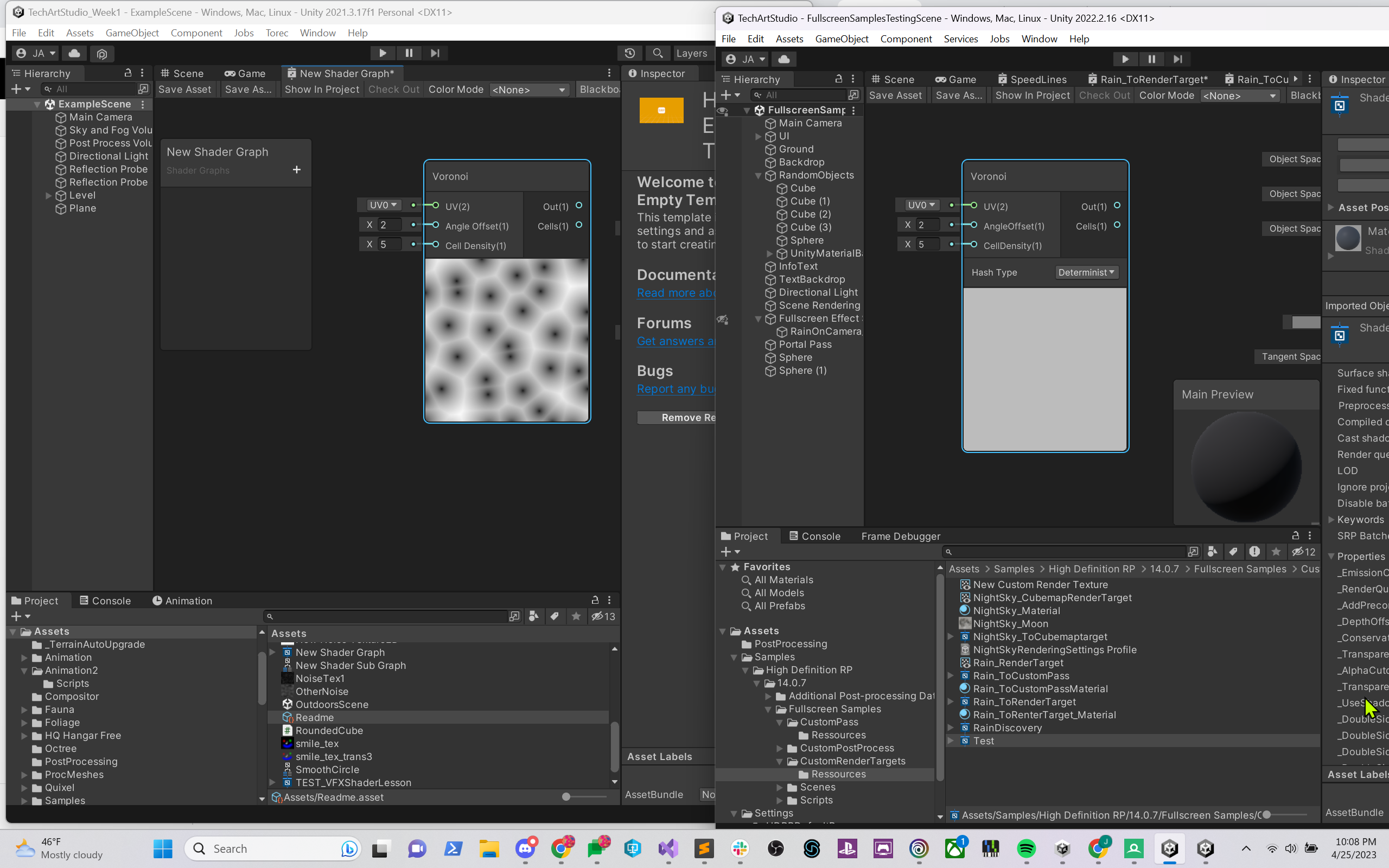
I'd love to not have to have both versions of the program up in order to show my students how this fullscreen shader works...
although I can copy nodes from one program to another, which works for now...
love to tell my students about a technique and then tell them about a workaround because there's something broken in the editor that renders said technique less useful...
Hello, I have a simple shader graph of a hollogram that I created in URP but I needed to change everything and go for the standar pipeline and my shader have a weird issue, When I look in the inspector or if I start the app, the shader is there but if I build and run, everything that have that shader doesn't showed. I saw online that I needed to add it to the "always included saders" section but it still doesn't work

Hello friends, I have a animation on the shader that was made using voronoi noise for a slash effect, but the problem is that I think the cells are too circular, I would like to Streeetch them if possible, but I can't find how
I try to multiply the resulting value but this made them change color
also try to use many types of offset, but still can't find a solution
Streeetch the texture in the case
Not sure, it may be a version bug, you could try using another variant of 2022 instead
since you are not using URP any longer, there may be a bug that lets you see URP in the editor even if you disabled it (or it can also be that you did not fully disable URP so its visible in editor but not in build)
hi ,
im still testing water with shader scripting but, I've a probably rather newbie question.
is it too bad if I added 3 float4 empty variables that wouldn't be used regularly but occasionally?
wdym?
if you don't have static branches it is always used by the shader
if you have connected them to logic they are used
it could be a good idea to create a separate shader with less features, if that is your question, but it depends more on what you do with those variables
if you just multiply something, or add it to something then it's probably cheap and you can get away with it
properties don't really matter unless you are passing in textures or large objects
Hey anybody knows whats wrong with my model
it looks perfect on blender
but the problem is
when i put a specific texture on model
it shows from this


to this
the flesh texture dont work
and other textures too
on the monster
You should import textures separately
Procedural textures must be baked to image textures
Why do you think that?
Importing the textures also involves creating materials for them and assigning them to the mesh, usually

i think something is wrong with the export setting
maybe
cause it is only the monster cant get textures
You can try assigning the baked textures in blender first, using mesh UV coordinates
Only UV mapped textures can be displayed in Unity without special shaders
ok i try that
that makes better sense
now it does it on unity

after i did sculpting on
it
it messed up the textures i think
The textures are surely fine, but the mesh likely lacks an UV map
Dyntopo for example resets any vertex data like UVs
funny i did use dyntopo
I have a simple shader in shader graph, which moves an object's verticies around. If I have more than one object with the shader on screen, they disappear. I read online that adding "DisableBatching" = "True" to the tags of the top most subgraph makes object space work again, which fixes my issue, but I couldn't find a way to make shader graph always do that. Is there a way I can tell shader graph to always disable batching for that one shader?
so how we fix that?
UV unwrap the mesh again
What type of objects / renderers is the shader used on when it seems to break?
you do not have any seams in your model
moving to #🔀┃art-asset-workflow
they're game objects with sprite renderers. They are moved ~100 units from world origin and have slicing enabled. No transform scale or rotating has been applied


exporting the shader code and disabling Batching using the tag fixes the issue, yet I feel like there's a way to not have to export the shader on every change
I will try to track down which nodes are causing this to happen
tracked the issue down to a branch instruction I have inside the shader

So, object space position alone still works? I'd expect it to break if sprites are dynamically batched into a single object space
what if you use uv's instead of object space positions
I am pretty sure it's related to batching, because if I create another material with the same shader, both objecs display at the same time
Here's a recording, if that helps
this is the generated shader code responsible for the surface if all the variable names were replaced by readable names

At this point I am just wondering if branching is causing it all to fail
@craggy torrent Sprites indeed batch. I'm not sure there's a way to break it in shader graph though, without editing the generated code like this.
Could assign different materials (or create material instances at runtime with renderer.material), that would also work but not ideal.
The other option is to avoid using Object space, or ports from the Object node. Depends on the effect you're trying to do.
the thing is that object space wasn't the issue I first thought of, but instead this simple shader
I'm not sure it "fails" exactly
Your graph sets alpha to 0 when position in object space is less? than 1
Which can happen a lot when batching suffles the sprites around
if all fails, then I will resort to copying a new material at runtime
does that also occur only when regarding only the y position?
but I can try moving some closer to the world origin


the center block is at 0 0, so the shader is working as intended, but just using world coordinates
I think this is somewhat a better visualization of how batching alters object space values
You have to assume that all the visible sprites are one object
Refer to Cyan's advice how to work around it

Could use UV coordinates instead
Though if the sprite is in an atlas the Y coordinate of the bottom/top is a only portion of that atlas texture, not 0-1
using UV coordinates fixes the issue. The shader won't be used in an atlas, so it should be fine. Thanks!
So should be fine as long as it's an individual sprite and not included in an atlas
So I am guessing there's no way to disable batching with shader graph at this point in time, right?
you can break batching in some cases by using override property declaration
Afaik that's only SRP-batching, not the dynamic batching thing sprites use
ah right, sprites
It'd be nice if sprite renderer wrote per-sprite UVs onto the vertices on another channel
Seems to also be plans to make sprites use SRP batching so I imagine that'll fix this too. https://github.com/Unity-Technologies/Graphics/commit/1c33741dc47b1ea8c5800dd9dd0d93b26b1c5c46
I have tried to replace object position nodes with UV nodes, but when stretching the sprite mesh using a sliced sprite, I loose my intended looks. I will try multiplying/dividing by the object's node scale and report if I still experience issues
Ah yeah, slicing will also change UVs
and the object node sadly doesn't fix stretching issues

sadly I also can't use tiling, since the voronoi texture isn't seamless
You could project the voronoi in world space coordinates. Assuming the sprites themselves don't move it should look fine
Oh, though you may want a tiling texture with that
the shader is essentially generating all of what's visible and the sprite renderer is only there to generate the square mesh. I have a seperate part of my shader responsible for the alpha mask applied to the object, which relies on object space coordinates
Maybe you could use MeshRenderers for these objects instead?
having them be mesh renderers instead actually works. I have no idea why the sprite renderer is behaving differently, but for now I will replace them with a mesh renderer
I think sliced retain the UVs of the whole original texture
Hi. I'm using Shadow Caster 2d. The problem is that it displays shadows on top of objects. How to make it take into account the sorting order? I have it dynamic by Y.

here are the settings on the character

there is a target sorting layer option there and you have set it to all
With this, you will get a mapping only to specific objects. Dynamic sorting is needed. I tried to change the code, but it didn't work:(
ok I finally managed to pull of the transformation from clip to world space. (This took forever) Turns out that there is a unity_CameraToWorld matrix in unity hlsl which I assumed was the same as the as camera.CameraToWorldMatrix. Turns out, it isn't! I have no idea what the difference is only that one works and the other doesn't, lol. I also made the silly mistake of using v.vertex instead of o.vertex which is the correct clip space vertex. Anyway at least now I am getting the correct results.
Not sure I don't have much experience with the 2D renderer's features and the 2D renderer in general
Is there a way to loop over the existing lights in the scene rather than using a second pass?
How can I get the height difference between the shader object and the view? This seems simple but I just can't get it to work properly
You can get height difference in math just by removing one positions Y coordinate from the other.
I think you can get view Y using a node's "view space" but I don't remember off the top of my head if you need "world space" or "local space" for the actual object's location.
Oh yeah might also need to be .abs for absolute number, so that you don't get negative distance
lol
Yeah ive been trying different combination of those but it produces weird results
I FINALLY DID IT

the position nodes didnt work because they return position info per vertex i think
hi,
could someone explain to me why in shader we use float2 instead of Vector2 ?
in fact, i've tried to use Vector2 it said its unrecognizable and all shader broke
its the same thing really
The shader language used in Unity is HLSL. In that language, it's called float2. The reason it's different is because not all developers agree on what to call their types. HLSL predates Unity, so maybe you should be asking why Unity doesn't use float2 instead.
@low lichen @lunar valley thank you ❤️ ❤️
i have one more question though , is it possible to use Sin()/Cos() in shader's script ? im trying to draw a sold circle
Yes, they are global functions in HLSL, called sin and cos
are they also available for cginc ?
For future reference https://learn.microsoft.com/en-us/windows/win32/direct3dhlsl/dx-graphics-hlsl-intrinsic-functions
The following table lists the intrinsic functions available in HLSL. Each function has a brief description, and a link to a reference page that has more detail about the input argument and return type.
thank you :)!
And if you are on the old build in pipeline that uses cg https://developer.download.nvidia.com/cg/index_stdlib.html
Cg Standard Library Documentation
I found a flaw in one of my shaders
The verts get deformed and then I recalculate the surface normals so that light works correctly
The problem is that I discovered if you rotate the mesh, this breaks the math
How do I fix this?


Do I pass in the object's rotation somehow? Or change the math to work in world space instead of object somehow?
If you're using tangents, you also need to recalculate those.
I might be? I am not sure, its complicated and ive been away from it for a length of time to the point that I don't grasp how it works much anymore

There's a Tangent output that is unmodified. It's required for normal maps.

the final compute is doing this, is one of these the value I need to Out?
Yeah, you should be able to just output modifiedTangent and connect that to Vertex Tangent.
Cool, trying that now 👍
That worked, the normals seem to work now even when rotated
weirdly it seems to rotate twice as fast enough

I am guessing it rotates twice as fast because its rotating when I rotate the game object, but its rotating AGAIN because of one of my transformation
hrughm, when I fix the rotation thing, normals break
but if I fix normals, it breaks the rotation
the problem to my undertanding is spaces

the three inputs want to be in object space? Or is world space okay? Or am I already in object space?
doing this fixes some problems but causes other problems

You need to give it object space values
what space should all these be starting in?

You can either stay in object space throughout or convert from world space to object space at the end
in earlier versions of this shader I appear to have mixed spaces, some were object and others were world
which probably was not doing me any favours
I will try setting them all to object at the start
everything in object space appears to be the ticket

i am beginner and i dont know why my material is pink ? anyone can help me ?

Usually the magenta error shader appears when the graph is incompatible with your configured render pipeline
Since your graph's active target is Built-In, it could be that your project is using URP or HDRP instead
Sorry, I don't understand what I need to do to fix the problem
If your project is using URP or HDRP, change the Active Target to match that from Graph Inspector over there
But if your project is using the built-in render pipeline, do not change the active target
like that ?

can anyone help me with unity keyword nonsense regarding custom shaders? writing a custom ubershader at the moment and adding support for LPPVs
which uses the following keyword
UNITY_LIGHT_PROBE_PROXY_VOLUME
however, its like its consistently on
and I have the keyword
#pragma multi_compile _ UNITY_LIGHT_PROBE_PROXY_VOLUME
mind you I've also tried without the underscore as well, same results
but its like consistently UNITY_LIGHT_PROBE_PROXY_VOLUME is enabled
should I be using a different keyword when an object is using LPPVs?
anyone from unity got any ideas?
how do you convert degree to radiant in shader HLSL ?
I looked it up and i found this https://learn.microsoft.com/en-us/windows/win32/direct3dhlsl/dx-graphics-hlsl-radians
when I tried it ret radiant = radiants(90) // 90 degrees celsius , it said radiants is unrecognized
Converts the specified value from degrees to radians.
or is familiar with these keywords
radians(degreeValue)
nvm i think i fixed it , i had a variable called radians as well , that was causing the confusion
Thanks ❤️
hi , im trying to loop in a shader script but, i keep getting on a forloop unexpected integer constant
for (int i = 0; i <= 90; i ++ 1) {} , what am i doing wrong? ... i believe this is triggered by i because when i changed the i to float , it said unexpected float constant
your syntax is wrong
for (int i = 0; i <= 90; i ++ 1) {}
i ++ 1 - is wrong
i++ is already a shorthand increment for incrementing by 1
so it'd just be
i++
altogether @pale python
forgive me but @nimble otter would you happen to know anything about "UNITY_LIGHT_PROBE_PROXY_VOLUME" and LPPV specific keywords?
thanks that was it 😄
but im still getting another error loop never exits
i have even tried i+=10 ... still loop never exists error
loop never exists means its an infinite loop
I don't think you are familiar with how forloops work
W3Schools offers free online tutorials, references and exercises in all the major languages of the web. Covering popular subjects like HTML, CSS, JavaScript, Python, SQL, Java, and many, many more.
i highly doubt that , i have been coding for more than 4 years , its just a bit weird in shaders
shader syntax is not that different
are you perhaps modifying the i value in the loop?
if you arent mabye try adding [unroll(90)] before the loop
well , w3school has this example
for (int i = 0; i < 5; i++)
{
  Console.WriteLine(i);
}
how is that different from mine ?
for (int i = 0; i <= 90; i ++) {}
doesnt make a difference , same error 😄
aye?
for (int i = 270; 270 < i <= 360; i++) {} also here
: infinite loop detected - loop never exits at
what line
I just pasted this line into a shader and no issues
for (int i = 0; i <= 90; i ++) {}
that is the exact line
        for (int i = 270; 270 < i <= 360; i++)
        {

        }
i used to have a function inside the loop but i removed it temprory for the error , just to know why the loop never ends
pasted it in, yeah it would mean your conditional is wrong
270 < i <= 360
for (int i = 270; i <= 360; i++)
no need for the 270 <
you already set variable i to 270
yeah that fixed it lol , thanks for your help , its weird that i still make dum mistakes like that 😄
it happens to the best of us so no worries
also nevermind, found my answer

URP is reporting that unity_SpecCube0 is not set when attempting to access it via a Compute Shader. Is there anything special I need to do to make this texture available?
I've added #include directives for GlobalIllumination.hlsl and UnityInput.hlsl, e.g.
#include "Packages/com.unity.render-pipelines.universal/ShaderLibrary/GlobalIllumination.hlsl" #include "Packages/com.unity.render-pipelines.universal/ShaderLibrary/UnityInput.hlsl"
The specific error is Compute shader (...): Property (unity_SpecCube0) at kernel index (...) is not set
I was able to access unity_SpecCube0 from a custom fragment shader with the same #include directives.
if your working in a compute shader most of unity's default variables will not be set unfortunately
you'll have to assign them yourself
Ah, gotcha. Thanks for the tip 🙂 How would I go about getting the SpecCube0 and SpecCube1 properties that Unity uses to set for the Fragment shader side so that I can set them manually? Is there an API I can pick them from? I imagine not but just looking to confirm.

That is what I was looking for -- thank you!
Not sure exactly what you're using this for but it's beautiful. Well done. 
https://cdn.discordapp.com/attachments/996979168304697384/1100885856857890866/image.png
thank yoou, here is what it looked like EoD

Oh hell yeah! 😄
I have a wierd problem with my shader. All I have is a sample texture node and it messes the alpha channel in some wierd way.


no clue what so ever what is going on...
does your texture that you are feeding it even have an alpha channel?
yes it does
with native shader it look all fine, but when I give it a custom Sprite Unlit shader then this happens
that red background is the issue?
giving that it should be transparent, yes it is
hmm and you have the graph in transparent mode?
also dont know if it matters but it is an UI image

RenderQueue is transparent I mean

looks correct in the material 🤔
render que... i dont know if i can set that here
but it should be transparent anyway
nvm that, UI shaders dont have that
I think?
what is more wierd I took a shader from already existing projects of a friend, where it worked just fine
also checked all rendering setting etc.
everything seems fine
only difference is Unity version, but not some drastic one, from 2021.3.12 to 2021.3.22
when I unusign material then it is all fine


Ok I found some thread on unity forum about some bug that appeared since Unity 2020 I think, with which you cant use custom shaders on UI elements with screen space overlay canvas, couse it just breaks for some reason. Changing canvas to Camera space fixes it
Hello hello ! Using shader graph (HDRP 2021.3 unity version), I'm trying to get some control on the strength of my shadows on a specific mesh so I'm looking for the Shadow tint node and play with the alpha of it. Unfortunately, it's greyed out. Any help to be able to have some control on it please ?

Hey guys, I am writting a compute shader for a GPU version of the Perlin Noise.
I've followed the Wikipedia pseudo-code, but the return texturemap is all black... Some one can review my code ? pls 🥹
It's very simple to understand I swear, But i need help to solve this pls, Or advise
well what about you show us your code
there are many reason why your texture might be black
THANKS ! I was waiting for your endorsement ^^
This to long... But with vs code
I put a lot of comments ^^ I hope it's not too overwhelming
I did a two-dimensional grid of gradient vectors

Perlin noise is a type of gradient noise developed by Ken Perlin in 1983. It has many uses, including but not limited to: procedurally generating terrain, applying pseudo-random changes to a variable, and assisting in the creation of image textures. It is most commonly implemented in two, three, or four dimensions, but can be defined for any num...
I did exactly like this
@lunar valley Do you think you can get a look ? 🥹
I will take a look at it but I won't guarantee anything also, have you debugged which part isn't working? You sure that the noise function is the incorrect part?
i think the problem is in the Noise(float2 pos) function,
the variable n0 is black, so the interpolation ix0 is black too,
So the interpolation of the value return black black.
I don't understand why
Thanks for helping ^^
How would I make the fresnel only appear on the top right of an object (no matter which angle I view it from, I don't care about the light direction)

using amplify or shadergraph, they're both basically the same
simply multiply your fresnel effect with the dot product of the normals and some direction you want
the world normals?
this is my setup

it doesn't move when I move the camera. I'm trying to get a sort of toon highlight that's always on the top right of the object no matter which angle I look at it from
yeah thats correct
again, it stays in one place
even when I move around the object
I assume it's because I'm using the world normal, but I'm not sure which node I would replace that with
oh well you can use the cameras up direction then instead, then the glow always gonna be up no matter from where you look at it
I'm sure there's a way to do it with Amplify
I'm just too inexperienced to know which node I need to be using
I do not use amplify so idk
if not you can always do material.SetVector
this is how it'd be done in blender

idk what the equivalent to the geometry node is in Amplify
it's just taking the object normals
I think it would be the "Vertex Normal" node
still seems to only appear on a single side of the model depending on which angle I look at it from
@lunar valley hey did you take a look ? If you didn’t can you advise me someone else who could ?
Hi, I have a question on NDC. Most materials I've read define NDC space as a cube with x, y, z ranges from -1 to 1.
And by perspective division, we can get a vertex's NDC from clipspace.
I encountered a line of shader code using unity shader library function ComputeScreenPos. I did not quite understand what this function does. And the comment said this function is deprecated and should use GetVertexPositionInputs. After some searching I happen to find this thread(https://forum.unity.com/threads/confused-on-ndc-space.1024414/) about GetVertexPositionInputson unity forum. The first answer is great and since the new function and the deprecated one basically share same logic, they make a lot sense to me now.
Then this is my question. In both functions, they all refer to the position as NDC. The first answer in the forum thread said
NDC is not just
clipSpace.xy / clipSpace.w,...NDC’s x & y have a 0.0 to 1.0 range.
This seems to contradict with what I've seen online. So does this mean NDC is not a fixed, rigid stantard, and you can define your NDC?


Unity Forum
Hello,
From textbooks, NDC space is clip space / w. However, I found some weird code in Core.hlsl in package com.unity.render-pipelines.universal....
Yeah, sometimes it's 0 to 1, but can also be -1 to 1. It depends on the engine / graphics API.
Unity defines it's range to be 0-w, which becomes 0-1 after the division by w.
Good to know. Thank you!
I have a tiling texture that represents spatial coordinates; I would like to sample it using bilinear filtering. If I use a point filter it works well, but obviously it looks pixely.
I floor the uvs and add them to the sampled texture values to get the "real" coordinates, but I get these problems on the borders of the texture.
I sample with Wrap Repeat, because if I use Clamp with a modulo 1, the effect is even worse.
Any ideas?

wow brain, sample using linear filtering will not work, it will blend with a completely different color 🤦♀️
I need to line up world space scale/coordinates with something that used to use UV coordinates but I am struggling to get the right values

is there a formula, what info do I need to get it to be 1:1? 🤔
so far any time I can see the actual stuf, its super tiny, and when I try to scale it up it scales off into the distance so the center is definitely wrong
but I cant figure out how to determine what those values should be
After much experimenting I found what magic numbers I need to make it look right but I am still unclear on why its those specific values that work
let me know if its not allowed here, but how do I get chatgpt to write proper shaders? it keeps throwing undeclared identifier errors on every shader it writes
By learning how to write shaders and fixing it
I considered that, but I was only gonna use it once, and the scope of the shader is way beyond me anyway so i didnt want to sink the time into it
I do not really understand with what you mean by 1:1. Uvs are ranged 0-1 world position isn't
chatgpt is dumb as fuck its just gonna keep lying to you. If it doesn't know something its gonna make something up. You can't expect chatgpt to write complex code for you. (yet (let us apprecciate these moments before we all get obsolete xD))
If you want to teach the chatbot to do the job right you need to get that proficiency you're avoiding anyway
as in whereas the plane's UVs were 0 to 1, world position'd UVs that sit exactly where the previous 0-1 did

in world pos it won't be 0 to 1 anymore
I found the 'correct values' but I dont know why they are correct
these are the magic values to take world position and align it to what the UV used to cover

so you are essentially trying to do worldpos -> uv?
I am trying to stop using UV for this plane and use worldPos instead, but see no difference at all when compared to mesh UV originally looked
because I have use cases that need world pos that UV can't supply
well I can see that you are scaling things down by multiplying with 0.01 or something, I do not know how big your plane is but could it be that you are just doing wPos / planesize?
well unfortunately I can't use any of that because I forgot that you can't sample a texture in the vertex step
so now I have to find some other way to pass the data I need to my shader
You can use SampleTextureLOD. if you want to plug this into the vertex input
oh, I will try that
Hey that worked, that solved me finding some other work around to mask away terrain deformation under props 

nice
This is actually so good looking.
Is URP unstable or something? Im expiriencing all kinds of errors after I install it
Sometimes my project wont save and sometimes there is a null reference or something
Also i dont have any scripts its a fresh project
It's not known to be unstable
I've got a lot of internal editor errors using 2021.3. in general, but in the rare cases they've broken functionality the fix hass just been a matter of restarting the editor
so I have a custom shader for materials that I want to receive shadows but remain invisible/transparent. I have the effect going pretty much how I want it except for one issue where it receives shadows but does not stop the shadow from casting past the object. You can see the issue here:

I'm not really sure how to fix this
Hello, I was working with the fullscreen shader graph introduced in unity 2022 to create a screen distortion effect, I am not that familiar with shaders and can't find tutorial for it online, would love any sort of help for it, Thank you
What type of screen distortion are you trying to make?
so I want to apply a screen freezing (as in ice) effect with distortion which starts from the edges of the screen to the center, and I just want to achieve some sort of distortion but can't seem to get it
Well I'm still not really sure what you want the distortion to do, but for ice you could use voronoi noise.
alright I tried with different noise pattern but the problem I am getting is to show it on the screen, like it is not transparent and it just covers the whole screen in that color, is there any node I am missing I don't know
Do you have the uv node plugged into the noise node
Also if you want transparency you will have to plug the noise into the alpha. I don't remember if Fullscreen shaders are transparent by default but if there is no alpha spot you need to enable transparency in graph settings.
keep in mind chat gpt has outdated info which sometimes is not valid in modern unity versions, and also keep in mind that you can not rely 100% on chat gpt, you will need to learn a bit of shaders by yourself for solving those problems
Uh, Its been a long time since I last used unity, glad it now supports screen shadergraph; anyways, you can create the border mask by using a spheremask node and adding a -1 to it so white color appears on sides rather than on center, and regarding ice, you will need to mess with some noise there . finally just multiply the noise by the sphere mask to get noise only on the corners
Exactly what I was thinking. I think voronoi noise would probably be the best for ice.
I have tried and mostly achieved the ice effect but the not sure how to achieve distortion like shifting the screen where the mask it present
Hmmm, I think you should combine it with some gradient noise too, voronoi noise alone would make a non realistic looking ice , or rather ice cracks looking effect if you only use the ridges
Not sure how the full screen shadergraph looks like now, but if it does not have a built in distortion node, you can plug the noise result into the UV of the camera or the texture that does the actual render, it will distort that texture
if that doesnt work then maybe adding the noise result + uv node and then plugging that into the resulting texture should do the trick then
sorry not well versed in shader can you name exact nodes to use for the uv of camera
I think the node is called URP sample buffer to get the screen texture.
And then you would probably just add values to the uv input of that
good question, I have no idea what the name for it is, as I said, I just noticed unity now supports shadergraphs on screen
I tend to use URP with ScriptableRenderPasses so I don't really know how Fullscreen shaders work that well either.
alright I will try the suggestion that you guys gave, thank you @full loom @silk wharf you guys are godsend
I'm not even sure what you did, so...
Hi! not sure where I should ask this, but I can see a shader being useful? so i'll ask here for now.
I have a texture with different discretized colors, for example the only red pixels will be (1,0,0,1) fully red, ie its easy to tell what color a pixel falls under. I want to count the number of pixels of each color in the texture and sum them in buckets, so i can tell if for example 50% of my texture is red, 20% yellow, 10% blue etc. Exact accuracy is not important, I just need generally which colors are there more of than other colors, and approximately how much more. Does anyone have suggestions on how to do this?
this sounds more like code rather than a shader, you should ask in a code channel
It's not that different from a normal lit shader, except I have the normals disabled so objects render as a pure 255,255,255 white object, and I have blending mode set to multiply
could i make a shader for a tilemap that takes in a parameter of a custom tile and uses that to change what it renders?
Hello, I am having an issue with taking a texture I made in blender into unity the texture looks fine in blender but when I feel like I am missing something. The eyes are a lot darker in unity but less so in blender I am using a Lerp node in unity to blend the 2 textures together.


Hey!
i have a trouble, never did shaders in my life in HLSL
_MainTex("Texture", 2D) = "white" {}
can i somehow make it take sprites instead of textures?
i have a sprite atlas
but that doesn't show up
If you reply to me, please ping
it's 1:33 am and i am slowly going to sleep now
thanks tho!
Hay I have a set of tiles and want to draw a outline of a specific color around a area of them to denote the range of say attack distance or movement range but I have no clue how to even start could anyone point me in the right direction?
Btw the tiles are 2D objects with sprite renders (not a tilemap)
What I can think of is you render the floor twice, one with shadow and stencil test pass, the other one without shadow and stencil test fail, then use the wall to write to stencil buffer.
I'm not sure but there should be a better way than above...
how can i turn albedo color, specular color, smoothness, emission color, and alpha into SurfaceData and feed it into :
Legacy code which unity changed at some point:
// The URP simple lit algorithm
// The arguments are lighting input data, albedo color, specular color, smoothness, emission color, and alpha
return UniversalFragmentBlinnPhong(lightingInput, albedo, 1, 0, 0, 1);
}
you are lerping between a texture and the color depending on the alpha of the texture why would you even want to do that
I'll look into this, thank you!
Does shader graph has analogue of "UnityObjectToClipPos" ?
Guys I just downloaded a shader and it makes my Texture look way darker on default.
In the documentation of the shader it says the following:
This is because of the gamma correction that is applied to textures when they are imported into the engine. In this case we want to use the texture as a linear data texture, meaning we want to use the rgba values as a way to store information instead of a color value.
Therefore we want to make sure this information remains unaltered by the importing process.
This can be achieved by making a small adjustment to the texture import settings for this particular texture.
In the “Import Settings” window, set the texture type to “Advanced” and make sure the “Bypass sRGB Sampling” flag is enabled. In the animation below you can see the difference between having this setting enabled and disabled. This can be of great importance when dealing with more advanced shader effects that make use of data textures.
But I cannot find that option maybe because the shader was made in unity 2018.

Any idea on how to make my shader use linear instead of gamma?
This option would be "sRGB (Color Texture)" in modern import settings

Well, not "nothing"
It does change the color space
Don't forget to apply changes
These are my settings rn.
Maybe another type is more suitable? The shader works in terms of effect. the problem comes to how the texture shows.

Your texture looks like it is a color texture, so maybe your shader expects a height map or something instead
We don't know how the shader works or even what it does so it's hard to speculate
Include "SurfaceInput.hlsl", initalise the struct SurfaceData surfaceData = (SurfaceData)0;, then set fields you need. I have an example here : https://www.cyanilux.com/tutorials/urp-shader-code/#simple-lighting
(or https://github.com/Cyanilux/URP_ShaderCodeTemplates/blob/main/URP_SimpleLitTemplate.shader)
Alright so. Let me lent you some more info.
The shader makes the diffusion effect you see in the middle.
All the other should stay unaltered.
The map you see in the middle of the diffusion ( behind it) it is just a copy of the texture without the shader.
That's the color I want to achieve. The default one.
This is the shader:
https://pastecord.com/jadigyjeqi.mm
And that's where I got it: https://gamedev.stackexchange.com/questions/175274/how-can-i-dissolve-using-dynamic-mask-objects
Hi! So I was messing around with the Shader Graph trying to make a dissolve effect for my map so I can make an animation where the map would color itself over time (I hope you understand what I want to achieve). The problem that I have it that as you can see in the video and images, the whole ground is very bright if I am using the material from the graph while if I use a normal material the part from underneath is darker, so any ideas what could I do to achieve those shadows ?


Since it's a surface shader, it's affected by lighting. Intended more for use on 3D models, not UI. So that might be why it's darker.
Should be possible to move the dissolve effects into an Unlit Shader.
How do I do that? Do I change something in the code?
It's bright because your effect is in the Emission port. You likely want to Lerp between the original texture and another colour (white) with the result of the Step in the T input. Then put into Base Color
Yes, it's not a simple change though - it needs rewriting.
If it's intended for UI, I'd copy the default UI shader : https://github.com/TwoTailsGames/Unity-Built-in-Shaders/blob/master/DefaultResourcesExtra/UI/UI-Default.shader
Then copy the dissolve parts of the code into that.
You are right. Disabling the scene light it makes it look okay in the scene view but not in the game view. Thats because it si a 3d project.. and I want it to be 2d basically.
Can I make teh lights off in general in teh scene?
Yep, indeed it works! Thanks!
I'm struggling with enable gpu instancing
anybody know why I have this behaviour?
I want to have a sphere around my object, but only the parts of this sphere that touches other planes needs to be shown. Anyone can help me do this?
I think it applies frag with wrong parameter, like it fails the index of prop
What pipeline is this? Is the shader a graph?
it's urp with shader (not graph, like hlsl)
Maybe something like this forcefield (or at least the "depth intersection" part of it), if you're in a pipeline that supports shader graph - https://www.cyanilux.com/tutorials/forcefield-shader-breakdown-simple/
The shader requires specific changes to work with GPU Instancing. https://docs.unity3d.com/Manual/gpu-instancing-shader.html
But, if you're in URP you should probably make it work with the SRP Batcher instead, as that's considered the replacement. For that the shader would need to use HLSLPROGRAM (rather than CGPROGRAM), include urp-Core.hlsl rather than UnityCG.cginc, and set up the UnityPerMaterial cbuffer. https://www.cyanilux.com/tutorials/urp-shader-code/#unitypermaterial-cbuffer
SRP Bathcer doesn't work with material property block, as far as what i read online
With the SRP batcher, you'd use different materials instead

Cyan... are you someone I know?
mmm, i'm not including UnityCG
@regal stag beat Saber?
Is a game? No idea what you're getting at
Lol someone on another discord of that game has the same name and the same color on his name
Well the colour is from roles, it isn't the same across servers anyway. "Cyan" is a colour, so isn't that uncommon.
Okay I thought you were the Cyan dude from there but apparently not 😂
Shader graph handles the object->clip conversion on vertex positions behind the scenes. If you're trying to convert code doing that, it's already done for you.
But if you need to calculate the clip position of other positions, can use the Transform node to go from Object space to World space. Then take the ViewProjection matrix from the Transformation Matrix node, and Multiply it with the world space input.
The mode on your Sample Texture 2D node is set to "Normal" which is intended for normal/bump mapping.
If it's a colour texture, you want to use the "Default" mode instead.
I tried to follow the tutorial to make the shader graph, but it comes out like this

Hey, I've downloaded a shader, and it came with a script too, but I don't know how to test the shader, can someone please help me out?


I do not know what text the shader should mean. If you want to use the shader you need to create a material and assign it to something
oh test
I meant test*
Yeah mb
I just wanna try the shader out to see if i can use it for me game, but ive only ever worked with shadergraphs, so im kinda confused
well I do not know what these shaders even do, so it is hard for me to say
I imagine the repo you got these from has an example scene? That should show how it's set up
I downloaded the package, but ill download the entire project and check it out once
or at least an explanation
But in general, with shaders, is it the same as the shadergraph where i can just right click the shader and hit create material?
yes
Generally yes, but I've found where those are from. The scripts use OnRenderImage to blit the shader to the screen. In that case it creates the material in the script for you. Would just place the script on the Camera.
But OnRenderImage will only work in the Built-in RP
Ah that makes sense, my project is in URP
well then it won't work
Alright, thanks a lot guys!
Hard to tell what the problem is from this image. But make sure the graph is transparent, and the Depth Texture is enabled on the URP asset.
Which one should I use?

For a 3D object, Lit or Unlit depending if you want lights to affect it. I'd probably use Unlit.
Wanna hear a pun?
Your shader looks lit
Anyone has a shader for built in that achieves this:

I want to have a sphere that highlights the overlap with other objects
That requires sampling a depth pre-pass texture to sample the depth at each pixel to calculate a world position and then checking if that world position is inside the sphere. In built-in, that's done through the _CameraDepthTexture shader property and with Camera.depthTextureMode set to Depth or DepthNormals.
More documentation about it here:
https://docs.unity3d.com/Manual/SL-CameraDepthTexture.html
Could also be done using stencil operations + ztest/cull. The old docs page had an example at the bottom
https://docs.unity3d.com/2018.1/Documentation/Manual/SL-Stencil.html
(though uses surface shader. You may want unlit template instead)
I tried doing it with with stencil, but I keep getting this error and I can't find info on how to fix this

Anybody knows how can I achieve this effect in shader graph?

That error seems to do with custom render texture assets, not stencils? Not sure if shader graph supports that. But stencils also can't be done with shader graph.
Tysm
Ty for explanation. i want this move to shader graph and i did it like this. Am i right?


In the case of the Vertex Position, Shader Graph is doing the transform to clip space for you. So shouldn't need to worry about it, just connect the subgraph output.
NonInstanced properties set for instanced shader??

Hey all, is there a way to programmatically add inputs and subgraphs to a shader?

does different property with material property block cause to break the gpu instancing ?
why I have this matrix in the shader prop?

awesome thank you for the help looks like that worked.
what the HELL are you doing?! 😅

how can i make the clouds blend with the skybox?
this is how i set up the fog so far:

set the fog color to be the same color as your background
oh man it didnt work when i did that before because i had a post process filter
after removing the filter and sampling the skybox color they are the same color now thanks 😄
not quite sure what you mean but if I understood your question correctly then: no
hi, is there a built-in variable similar to SV_InstanceID with the total number of instances indicated in the DrawProcedural call?
@cosmic prairie @lunar valley heh an organized spaghetti mess? Essentially there is a basemap (the first node), then there are layers(all the nodes after) in which i control the uv position, tiling and offset with a generated gizmo. I was hoping to be able to dynamically add in or take away the "layers" instead of having a hard set amount.
you can't do that, the only way I could imagine it being possible is to use a for loop inside of a custom function
Alrighty, thanks! 👍
No.
ty, do you know of any resource listing the SV_ variables available? I'm getting nothing from google and I'm not sure I'm using the correct terms to search
I did get a list from chatgpt but I don't know if it's complete
do not trust chat-gpt
A semantic is a string attached to a shader input or output that conveys information about the intended use of a parameter.
If you need the total instance count, you can pass it to the shader through the material or through MaterialPropertyBlock
tyvm!
yep I ended up doing that
Is there a way to preview or just strip shaders inside editor? I am stripping shaders in build using IPreprocessShaders, but this takes time to build it, it would be nice if I could strip it while in editor to see how will it end up.
Anyone know why this preview is pink? Multiplying a normal vector by a scalar seems like it should work...

The default/preview value of the Object node Position port is (0,0,0). So when normalising, it's dividing by zero. That tends to cause unintentional behaviour like this.
Hmm, I would have expected the normalize preview to be pink if it were NaN
that was the problem though
hi ,
does anyone know how to make a custom's shape edge's gradient from solid transparent?
I have asked this before but it was late at night so im asking again. I'm making an octree in a shader, but I am confused on how to create the Texture3D which stores the tree. Do I create the tree texture on the CPU then pass it to the GPU? If so, how do I do that cause I am trying but cant figure it out.
On the CPU I got most of the code I think, iterating though the tree recursively to assign values to the texture. But I don't know how to fill in the texture with the RGBA values and at what 'pixel' i should set. The RGB values are either pointers to another node by index, or to a leaf. The A value says whether the node's child is a leaf, empty, or a branch.
I used this documentation before to create a 3d noise texture. I saved it as a file and then attached it to a material. https://docs.unity3d.com/Manual/class-Texture3D.html
im trying to store an octree in a 3D texture so that i can pass it to the gpu
i need to know how to store it
should i create the texture on the cpu even? Cause i dont know how to do it on the shader side and cant find any examples online
not just trying to render a 3d texture, but that is useful too
how do you guys apply fade to the edge of your shapes ?
I asked before if you could use a structured buffer instead of a texture. Unless your target platforms don't support them for some reason, that's the way to go IMHO.
The structure is built with index pointers to other nodes of the tree.
Leaves just have 0 valued or -1 valued pointers since there's no next-node
i was trying to follow an article on it because i have never worked with octrees before. I didn't understand the article very well and the c++ example with cg code was complicated. But okay ill try to do that
Well, you CAN do it with a texture, but you're more limited as to what you can store, being limited to a <scalar>4 type:
see texture formats https://docs.unity3d.com/ScriptReference/TextureFormat.html and https://docs.unity3d.com/Manual/class-TextureImporterOverride.html
That said, if you want to use a texture with a float4 or 16 bit uint4 you can do that, it's just awkward.
OTOH if you're trying to run on really old or weird hardware, you may want to use a texture2D. YOU have to tell us what hardware you want to run on. Since you're trying to use a Texture3D, you'd need SM 5 anyway I think. And SM 5 supports structured buffers.
That's all filed under "IIUC"....
My hardware can support structured buffers. im trying to create one right now
Cool. That's easier, IMO.
is it possible to pass my own struct though a shader?
YEAH! That's what structured buffers are...your own structure. Big grin 🙂 Banana dance time.
i mean my own type
but what you don't have in shaders is recursion.
like a class or struct
Struct. Yes. YOU define the struct. But you'd want to use GPU native types...ints, floats, and such.
so like Struct Node{int typeOfNode; int value0;} RWSrtucturedBuffer<Node> octree;?
and then i just match that struct on the cpu?
Yep
Several new resource types have been added in Direct3D 11.
{
    float4 Color;
    float4 Normal;
    bool isAwesome;
};
StructuredBuffer<MyStruct> mySB;
....
float4 myColor = mySb[27].Color;```hi , I managed to get the shape i wanted ,
i still trying to figure how i did it lol
but for now , does anyone knows how to make it fade ?

why is this 1-a

while this is a ?

and this is a/2 ( less alpha )
how is alpha being caluclated ???

I don't understand what the question is, all of these results surely just make sense
make it fade by multiplying the alpha by a fade amount, 1->0
I just dont understand how shader works under that hood , how a value between 0-1 that should only represents the alpha parameter of the object perform a cutout or a cutin ? , when i tried to divide it ( assuming its like 0.5 or 0.3 = cutout / 2 then the expected results a smaller cutout ? .. but no, it effected only the alpha of the same cutout)
Why would scaling the alpha of a fragment change the shape? It of course will only fade
Each pixel has a 0->1 value representing how transparent it is. If you multiply that by a value less than 1 it will make it closer to 0, and therefore more transparent. Only more complex maths can affect shape
Unless you had the transparency defined as a gradient and clipped it against a threshold
HI everyone, I'm following this tutorial on compute shaders but it was written for Unity 2020 and I'm on 2021.
The macro UNITY_PROCEDURAL_INSTANCING_ENABLED no longer exists, and unity_InstanceID is undefined.
Any idea how I can port this to 2021?
Shader "Graph/Point Surface GPU" {
    Properties {
        _Smoothness ("Smoothness", Range(0, 1)) = 0.5
    }
    SubShader {
      Tags { "RenderType" = "Opaque" }
      CGPROGRAM
// Upgrade NOTE: excluded shader from DX11, OpenGL ES 2.0 because it uses unsized arrays
#pragma exclude_renderers d3d11 gles
      #pragma surface Surf Standard fullforwardshadows addshadow
      #pragma instancing_options assumeuniformscaling procedural:SurfProcedural
      #pragma target 4.5
      struct Input {
          // contains world position of what gets rendered
          float3 worldPos;
      };
      float _Smoothness;
      void Surf (Input input, inout SurfaceOutputStandard surface) {
          surface.Albedo = saturate(input.worldPos * 0.5 + 0.5);
          surface.Smoothness = _Smoothness;
      }
      #if defined(UNITY_PROCEDURAL_INSTANCING_ENABLED)
        StructuredBuffer<float3> _Positions;
      #endif
      float _Step;
      void SurfProcedural ()
      {
        #if defined(UNITY_PROCEDURAL_INSTANCING_ENABLED)
          float3 position = _Positions[unity_InstanceID];
          unity_ObjectToWorld = 0.0;
          unity_ObjectToWorld._m03_m13_m23_m33 = float4(position, 1.0);
          unity_ObjectToWorld._m00_m11_m22 = _Step;
        #endif
      }
      ENDCG
    }
    Fallback "Diffuse"
  }
how the shape is formed in the first place was the mistery , sorry sometimes i just forget stuff from all the work , thanks for reminding me 😄 , so yea my code actually turned some pixel's alpha to 0 that is why i can see a cutout and cutin xD
thanks 😄
is there is some sort of debug.log() function for shaders ?
Theres not but you could try something like this if you have problems debugging your code: https://docs.unity3d.com/Manual/SL-DebuggingD3D11ShadersWithVS.html, https://learn.microsoft.com/en-us/previous-versions/visualstudio/visual-studio-2017/debugger/graphics/hlsl-shader-debugger
Some people attempted to create a node that displays the value:
https://gist.github.com/aras-p/657a4947bb8a4549fda53a84bb91fb25
That's not even a compute shader, so..... ????
Maybe the unsized array warning is due to the macro not existing, IDK.
What @dim yoke said. There's also PIX and then GPU vendor-specific tools if you really want to dig in deep.
hi!
im trying to make a simple edge detection shader but no luck any good tutorials?
are you looking for post processing shader or fragment shader?
and what sort of edges you want to detect? discontinuities in depth, normal or something other like object outline?
https://www.youtube.com/watch?v=J_mJQqbuGac&ab_channel=niuage
a bit like this

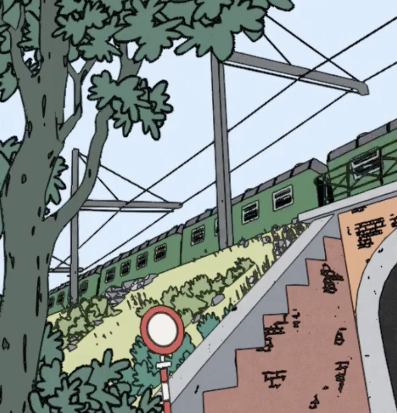
Used an outline shader based on color difference, depth, and normals to give a hand-drawn look to a 3D scene.
Built with Unity.
#unity #hand-drawn #outline #shader #japan
what I'm assuming they are doing is they are doing a edge detection and then adding some distortion to make it look hand drawn
wait hang on
https://www.youtube.com/watch?v=1vJx-YLYOgc&ab_channel=niuage
in another vid in the comments they link a website from where they got the code

I've been in love with Krzysztof Nowak's work ever since I first stumbled upon it. This scene especially inspired me: https://www.artstation.com/artwork/L39Xyl. I thought I would make a freaking amazing game.
Well, I didn't quite turn it into a game, but I had fun making it 3D, adding elements from some of his other pieces.
I couldn't come clo...
my problem was solved
Drawing outlines as a post-processing effect in Unity.
small hickup i dont think vector 1 exists..... do i just use a float?

Yes, they're the same thing
cool
now i have another problem
but this goes in #💻┃code-beginner not in #archived-shaders
I broke one large mesh into individual pieces, but lost the smooth shading effect in the process, is there a way i can compensate for this by rounding off the normals of each plane in the shader? It is a cross section of a sphere, so I imagine there must be a trick i can use given the radius

The easiest way is to just take the average normal from the neighbouring vertices
well, normal of sphere is really straight forward, you will realize it if you ponder it a bit (hint: how would you use the vertex position to get the direction?). but why don't you calculate the normals correctly on the mesh generation script as life said?
I used blender to create the objects, not a script, however I found a way to correct the normals using blender
what's up with my unlit sprite shader graph? why is the alpha channel ignored?

in this second picture, the alpha is supposed to be 1, the mask should be white

Previews on nodes don't show transparency, only the RGB data
The node is masking the Vector4 to only include the alpha channel, so the result is (0,0,0,1)
got it... it's still weird tho

i feel like it should just display white on the right side
Perhaps you want the Split node instead then to convert it to a Float rather than Vector4.
alright, the main preview should a completely transparent image, makes sense

but what is this? which value of alpha is being converted from the RGBA output??

I'm learning shadergraph and tried to make a simple water/goo shader, and it turned out pretty well on a small scale, however on a large scale it repeats often due to the Voronoi not sampling a large enough area, which makes it look very bad & repetivie. Anyone know how I can fix this?
When going from a Vector4->Float it would use the red channel. You'd instead want to Split, or just connect the A from the texture sample.
You can also just connect the RGBA from the sample to the Base Color, which would truncate it to RGB.
I figured this out by using the position node, and it looks fine in the preview but for some reason the voronoi effect is extremely stretched along one axis when I apply it. No the plane is not stretched in any way


got it, thank you!! if I understood it correctly, when unity wants to convert a Vector4 to a float it just chooses the first channel (in this case R) since it doesn't have a way to know which channel I want to use; and that's why I have to split it myself and plug A into Alpha


have it be one mesh
It is one mesh its a subdivided cube
Hey everyone, I have a problem with a code snippet that I found online that basically should render volumetric clouds trough ray-marching and signed distance fields. The problem is that I don't know how to implement this code snippet into my project. Can someone help me figure out a way of doing that for rendering volumetric clouds in the editor?
(I will provide the code snippet in some minutes btw)
Here is the code
@dim yoke @cosmic sphinx @meager pelican thank you so much , fortunately i got my problem fixed but thanks for sharing , i will visit them for possible future problems
why does this edge around the uvs from shadergraph happen

Hi! i want to pass a set of points into a shader, and have the shader find each pixel's distance to the nearest point. As far as I understand, GPUs don't work with loops, so does anyone know of a way I can do this? The only problem is I can't guarantee the number of points passed to the shader at any time, it could be anything from 1 to like 30 or 50
Can someone help me with some HLSL stuff? I am very much so a beginner at making hlsl scripts, and this one isn't working, and I cannot find the HLSL function for what I want to do, which is to take "LUT", (which is a Texture 2d), and get an output of the pixel color at the given coordinates.

So I input an X and a Y, and a texture 2D, and the output is the color of a pixel on that texture.
I'm deeply sorry if this is a stupid or unworkable question, but I tried to figure it out on my own and was unable to.
I basically just want the output of this to be the color of the texture at a given pixel coordinate, but I'm unable to find documentation explaining how to get an RGB value of a given pixel at a given coordinate on a specific texture image
"Texture Coordinates" in shaders are best expressed as UV's in normal shaders. I'm uncertain what type of shader you're writing, compute shader or normal vertex/frag/surf shader or what pipeline you're in.
UV's are basically percentages across or up the texture, 0,0 being the lower left and 1,1 being the upper right. They use a vector2 (called float2 in shaders). And the GPU has to SAMPLE the texture at the given point. And there's different sampling settings, but those are on the texture import, or they can optionally be overridden in the shader.
Anyway, what you're actually looking for, I think, is a function called tex2D(textureName, UVvalues). Maybe you want a helper macro called SAMPLE_TEXTURE2D(textureName, samplerName, UVvalues) which is "more modern".
Here's some links:
https://forum.unity.com/threads/difference-between-tex2d-and-sample_texture2d-post-processing-effect.651580/
https://learn.microsoft.com/en-us/windows/win32/direct3dhlsl/dx-graphics-hlsl-tex2d
In Unity the sampler and the texture ref are usually the same name. But if you really want to get confused you can read this:
https://docs.unity3d.com/Manual/SL-SamplerStates.html
Unity Forum
What is the difference between tex2D() and SAMPLE_TEXTURE2D? I am trying to create a four corner pin post processing effect, and my lines come out...
Samples a 2D texture.
I'm writing a Shader-Include for a post-processing shader in HDRP
Apologies for my clumsy questioning, I'll try to use what you showed me here, and come back if something goes wrong.
np, but be aware that colors in HLSL usually range from 0 to 1 values in each channel. So just like in the UV case, you'll have to do the math to convert things. And be aware that out of range values may wrap or do whatever the sampler state is set for (like clamp).
I'm having another issue
specifically, it's not liking the fact that I'm using a texture2d
Here's the specific errroor

and here's what the current code looks like
I think I need to somehow get a sampler2d instead of a texture2d?
but I don't know how to get that
if that's what it's wanting
Yeah, I'm not sure what's going wrong here.
OK, firstly, if you're in HDRP why can't you be using Shader Graph?
Secondly, as I mentioned, the UV values have to range from 0 to 1, so are your inputs such that they do that?
Thirdly, the "T" is NOT capitalized in tex2D
I don't know how to sample a specific pixel in a texture in Shader Graph, and am writing a custom fuction for it.
I am going to troubleshoot for the UV values once I have something that compiles at all.
corrected accordingly.
Apologies if I'm being frustrating, I'm just very new to this, and trying to figure things out.
Is there a way using shader nodes to get a specific pixel on a texture, and output its color?
You're fine, np. It's just that I lack context for my answers 🙂
Compute the UV value.
I'm making a custom LUT implementation
because unity's LUT does not allow Point Filtering for 3D textures
wait
pixelX/width, pixelY/Height.
...
Okay, so
having read that
I might be coming to the conclusion that I'm stupid as hell, lmao
I had a little jeopardy theme playing in my head as the gears cranked and I realized that's literally what UV coordinates are
There's ways to simplify your code too.
For example you have a float3 coming in for SceneColor. You don't need to break it out into 3 variables.
You can just reference the .r, .g and .b directly and save 3 variables. I mean the shader optimizer will probably do that for you anyway, but still, shader programmers are used to reading things like
float2 blah = float2(SceneColor.r * SceneColor.g, SceneColor.b); or whatever you end up actually using.
ugh
I don't know what I'm doing wrong.

So, here's my current shader.
it converts the RGB values of each pixel on screen to a UV coordinate, and an Array Entry, which it then feeds into a 2D Texture Array, 32 by 32 pixels, and with 32 entries in the array
but
I can't seem to figure out what values the color is actually outputting
because no matter what, what comes out looks like a muddled mess.
Well, I give up. I can't figure out how to fix this, no matter what I do.
I assume you mean those scratches which could be caused by uv discontinuities on texture sampling. Disabling mipmaps on the texture would help, though calculating the mipmap level yourself would still allow using mipmaps for better looking textures
i dont know what happened. i just fixed my pc and now it has an error. i reinstalled easy inputs and visual scripting
I dont see how this has to do with shaders in any way. That error seems to be coming from visual scripting package
sorry i was in wrong channel and didnt see. but its fixed now
im fairly new to vertex painting. in blender you can have different vertex paint layers. is it possible to access the layers in unity? if so, how? im currently just using the vertex color node in shadergraph for one layer.
guys how to edit gradient in shader graph in unity 2021.3?
"Vertex colors" are really just data stored with each vertex in the mesh. Verts have data that can be set in C#, so you should get familiar with how to build a mesh in C#. You can then manipulate it to "paint" using either a color stored in the vert data, or a location (UV map) that references the colors in a texture. The usual use of UVs.
So here's the mesh definition:
https://docs.unity3d.com/ScriptReference/Mesh.html
There is a single dedicated color attribute of a vert, but there's also at least 8 UVs. You can stuff additional color data into UV data (which can be a float3 or float4). You'd write the shader to use that data. Be aware that some UVs are used for lighting.
As to how blender maps those multiple vert-paint layers to the mesh data, IDK.
The usual technique for debugging shaders is to output values AS A COLOR (remapped as necessary).
So in your case, I'd start on the left of the graph and output values to base color, maybe re-mapping as necessary to get them to a 0-1 range. You can then "see" (and use a color picker) the values showing each step as you map each step.
How would i go about highlighting all edges on a mesh? That's a needed effect for the game i'm working on yet i can't seem to find anything recent that works with URP and is comprehensible to me considering i'm really bad at shaders
I'm basically not using any lighting whatsoever in the game, using simple shapes like cubes, pyramids and basically any simple shape that you could count the number of faces so its the only way to make them not look flat
I could manually use a texture but i plan on making the meshes change shape a lot, and if i did use textures i would probably need to use a high resolution image for it to not look bad
I am generating NaN somewhere in my shader. I am currently trying to hunt it down by checking if a float is NaN and returning early
is there a better way to do this? I imagine you can't just attach a debugger to a shader, of course...
in the meantime, I think I tracked this down to me sending a NaN in because of bad script logic
so at least this one's resolved
Nvm i'll just make a blender script to inset each face on a model then export that
Search for "wireframe shader", if that's what you mean by "all edges".
Oh thanks that looks a lot more promising
You can actually, with software like RenderDoc. Of course, it's not as simple as setting a breakpoint. You have to choose which vertex/pixel you want to debug and then you can step through the vertex/fragment shader for that vertex/pixel.
ah, cool, i'll look into that (on my windows machine) if something gnarlier comes up
I got to find exactly what i wanted, thank you
Is this the appropriate channel to ask about Compute Shaders? Or should I use #archived-code-advanced?
Given the word compute shaders and the channel called shaders, I'd think here.
sounds good to me!
hello, i have been trying to create a puddle shader but i get non shiny puddles, why may that be?

looks kinda shiny to me
perhaps you should adjust the color that you blend to get the smoothess
raise it to a mid-gray and it'll look shinier overall
you see those spots created by the noise texture? those are not shiny at all
Hi, does someone knows a page or documentation where I can read about the programming language and libraries used by ComputeShader?
I.e: which math functions have I available, stuff like SV_DispatchThreadID and other magic parameters, etc?
As you may notice, I'm inexperienced in this hehe
The language is HLSL, so https://learn.microsoft.com/en-us/windows/win32/direct3dhlsl/dx-graphics-hlsl
That applies to all shader types though, not just compute. It's also probably easier to learn from Unity-specific tutorials.
SV_DispatchThreadID is known as a "semantic". There's a page on them : https://learn.microsoft.com/en-us/windows/win32/direct3dhlsl/dx-graphics-hlsl-semantics
As for math functions available, the intrinsic functions page lists those (specific pages should tell you if a function is limited to specific shader types) : https://learn.microsoft.com/en-us/windows/win32/direct3dhlsl/dx-graphics-hlsl-intrinsic-functions
Thanks
Which shader model uses ComputeShaders?
Hi,
I have two meshes next to each other using the same shader.
I want to have them look like mountains and look connected
I added a shader that raises the height of a vertices based on world position and a gradient noise
I offset the noise by the world position too
If the two meshes are sat on top of each other they, look exactly the same, but if I put them side-by-side, the vertices do not line up. It is worth noting that the edge vertices are in exactly the same positions in world space to my knowledge. I must be doing something fundamentally wrong, but not sure what

My shader is just me experimenting, so I kinda expected it to be wrong, but I am not sure where

So, from what I can tell, it's almost right?
If I look at it top down, looking at the gradient noise and move it left to right, the noise moves slightly in the opposite direction to the direction I move the object
So it's moving with the offset, but not enough?
And that seems to be why it doesn't line up with two meshes side by side
ok, fixed it. Apparently I just didn't need tiling and offset at all and it was what was offsetting it to begin with
what do you mean by that?
In the microsoft documentation of HLSL, some features has "Minimum shader model"
So I was wondering if Unity meets the requirement of that "shader model"
I do not know, most of the functions there that I am using relatively regularly are from min shadermodel 1
I don't understand why this compute shader is not zeroing the array:
RWBuffer<int> actualParticlesCount;

[numthreads(64, 1, 1)]
void ClearActualParticlesCount(uint3 id : SV_DispatchThreadID)
{
    actualParticlesCount[id.x] = 0;
}
int clearActualParticlesCountKernel = computeShader.FindKernel("ClearActualParticlesCount");
ComputeBuffer actualParticlesCountBuffer = new ComputeBuffer(64, sizeof(int), ComputeBufferType.Raw, ComputeBufferMode.Dynamic);
int[] actualParticlesCountArray = new int[64];
computeShader.SetBuffer(clearActualParticlesCountKernel, "actualParticlesCount", actualParticlesCountBuffer);
computeShader.Dispatch(clearActualParticlesCountKernel, 1, 1, 1);
actualParticlesCountBuffer.GetData(actualParticlesCountArray);
// actualParticlesCountArray contains non-zero data ???
And what keyword do you use in discord so HLSL is highlighted?
what is it instead?
Random numbers, and very large
maybe try a structuredbuffer instead
I deleted ComputeBufferType.Raw, ComputeBufferMode.Dynamic from the ComputeBuffer and now it seems to work
🤔
computebuffer type raw is for byteaddressbuffers or rwbyteaddressbuffers
Oh, thanks
np
I noticed that InterlockedMax and friends only works in int and uint... what should I do then if I want float?
(I am iterating an array of positions and wanted to store the largest and smallest of them)
You could choose an integer range to map the floats to.
I would loose a lot of precision 😦
That would depend on the range you need. If it's just between 0.0 and 1.0, then mapping that between 0 and uint.MaxValue is more precise than what float can store within 0-1.
Alternatively, I could store both a float and an integer. I would use Interlocked on the integer to use it as a "lock" while modifying the float.
int, uint and float are all 4 bytes, so they're all capable of storing as much data. It's just a question of how you map it.
I don't think interlock works that way.
Oh right, I can emulate interlocked max with compare exchange and reinterpret the int to a float
It doesn't, but if you define two values "LOCKED", "UNLOCKED" then you can emulate a basic lock with it, I do that in C# sometimes when I know will be faster than an actual lock
How can I reinterpret values in HLSL? I'm not finding how hehe
not quite sure what you mean by that yet
Just found asint and asfloat
I think this would do the trick, didn't test yet:
void InterlockedMax(in int slot, float value)
{
    float old = asfloat(slot);
    while (true)
    {
        float newValue = max(old, value);
        int newValueInt = asint(newValue);
        int original = 0;
        InterlockedCompareExchange(slot, newValueInt, old, original);
        if (original == old)
            break;
        old = asint(slot);
    }
}
When I try to use interlocked I get:
interlocked targets must be groupshared or UAV elements at kernel
The error is produced in the commented line:
void InterlockedMax_(in float slot, float value)
{
    float old = slot;
    while (true)
    {
        float newValue = max(old, value);
        int original = 0;
        //InterlockedCompareExchange(asint(slot), asint(newValue), asint(old), original);
        if (asfloat(original) == old)
            break;
        old = slot;
    }
}
I am not sure how to fix this 🤔
Aaah, there's a channel for shaders!
Im moving my question from code advanced to here
What would be the best way to schedule dispatch calls of a compute shader so that there's only one or two running at the same time?
I have to dispatch a compute shader, let's say 100 times, I would like to do it in packs of 5, so that the GPU stays busy, but not with memory overload
Not sure how could I schedule them, like in a queue or something
I tried using a graphics fence, but I'm running other compute shaders, that don't need scheduling, that would trigger the fence too
Why don't u cast to int?
Like float value = (int)wathever
(i meant the asint, not sure if it would solve anything of the main issue)
Because that would reduce the value, i.e: 5.7 -> 5. Instead I do a "bitwise" cast, as I only use the integer for the interlocked swap operation which only supports integers
So you would like to transform that 5.7 into 57?
The asint reinterpret the bit content of the float to an int (that is, it creates a non-sense number), however that is not a problem, since I only use that integer to do the interlocking
Aaah I see
So you're using Graphics.ExecuteCommandBufferAsync to add the dispatch to the async compute queue? Normally, only one dispatch will be run at a time. I'm not sure how async compute changes that, but I'm pretty sure that's only letting you run it alongside other non-compute tasks on the GPU (i.e. graphics). It doesn't let you run multiple compute dispatches at the same time.
Im not using that, I have a for loop that dispatches multiple compute shaders
Then they will run in sequence.
If you do:
computeShader1.Dispatch(...);
computeShader2.Dispatch(...);
Graphics.DrawMesh(...);
computeShader3.Dispatch(...);
Then the GPU will do those things in that order, one at a time.
Oh, i see, i thought the dispatch was called instantly and didn't wait for the shader to finish before executing the next one
It is. All those methods are just adding the commands to a queue, which is later submitted to the GPU on the render thread.
I see
So, what would be the best way to schedule those dispatch calls?
So that there are more queues but shorter ones?
The GPU can only do one thing at a time (but each one thing can be massively parallelized to finish quicker), unless we're talking about async compute, which only some platforms support.
So at most, you can schedule those dispatches to the async queue (assuming your target platform supports it), but that only allows those dispatches to run at the same time as graphics related tasks, like draw calls. Your dispatches will still be sequential.
Yeah, it's not a problem if they are sequential, i just want to spread them in multiple frames so that Unity doesn't get stuck waiting for all of them to run
Then you must use the async queue, because otherwise those dispatches will stall the graphics queue and not let the GPU draw the frame.
If you want to spread the execution over several frames, you'll need to implement some kind of queue that keeps track of the frame time and only dispatches shaders when it's within the time budget.
Is there any callback that would let me know if the compute shader is done?
AsyncGPUReadback as I mentioned in the other channel.
Mmmm
I'm not sure that would work in combination with async compute. Since AsyncGPUReadback is just requesting to read a texture or buffer, it's not really concerned about what needs to write to it before it can read it.
And CommandBuffer.RequestAsyncReadback is not one of the allowed commands to be submitted to the async queue:
https://docs.unity3d.com/ScriptReference/Graphics.ExecuteCommandBufferAsync.html
So, mmm, i don't really need to read anything from the compute since all the data generated is only later used by other compute shaders and never by the CPU. However, i do need to know if the first one is done so that the next can run. The next one runs every frame and is lighter. So what Im doing now is execute dispatch on first, add an object with the bufffers on a list, and at each update check the list for the new compute shaders
What i want to say with this is. Is there a callback that can be executed to add an object to a list on the cpu, after the dispatch is finished?
hi ,
how do you guys draw outline of a custom object ?
my current method may not be the best and i wanna hear about yours .
so im basically drawing the object twice ( its not a rectangle of course , it has curves and stuff )
and i just delete the smaller part and keep the bigger one
is this is the right way to do it ?

by delete , i mean setting it's alpha to 0
This looks useful for my second case, but, could i run DrawMeshIndirect through that async dispatch?
It's the thing, I have all my data on the gpu, and I would like to do it all from there, but i still need to use the cpu for draw mesh indirect for example and I'm not sure why
If your compute shaders are generating data required for a DrawMeshIndirect call, then surely they must finish before the frame ends, right? Otherwise there might be frames where the mesh isn't drawn or is drawn with old data?
With async compute, the idea is to use fences to synchronize the async compute pipeline with the graphics pipeline. So in your case, you could dispatch the compute shaders as async, creating a fence after they finish. Then in the graphics queue, you wait on that fence before calling DrawMeshIndirect
True
So, back to the first problem. Solution A, async compute, create fence, wait for all to finish, and then start executing the rest of the compute shaders (the second part that will draw mesh instanced)
Is there a solution that would allow me start to execute the second part and draw the mesh as soon as the first part is finished?
The problem with all of this is that im calling so many dispatch that I cross a memory treshold I think (my gpu crashes if I call to many, and says "system running out of memory"!)
You mean something like this?
CommandBuffer asyncCmd = new CommandBuffer();
asyncCmd.DispatchCompute(firstShader, ...);
GraphicsFence fence = asyncCmd.CreateGraphicsFence(...);
asyncCmd.DispatchCompute(secondShader, ...);

Graphics.ExecuteCommandBufferAsync(asyncCmd);

Graphics.WaitOnAsyncGraphicsFence(fence);
Graphics.DrawMeshIndirect(...);
This would add the two dispatches on the async queue, while the DrawMeshIndirect only waits for the first dispatch to finish.
The number of dispatches shouldn't contribute to any significant memory allocation, unless you're creating GPU resources (buffer/texture) alongside each of those dispatches.
just to know , am i asking a dumb question or is it too complicated for everyone just as for me ?
i'm still testing the water with shader so i dont know
That message:
interlocked targets must be groupshared or UAV elements at kernel
means that wherever you're storing this data, you don't have the right type of object.
You need (as the message says) a data structure in group-shared memory (shared "locally" by all threads in the thread group) or in a UAV (unordered access view). Basically UAV is random R/W memory area that the GPU knows to keep track of as such, and can be read and written all over the place by many threads at once. Structured buffers are UAVs, for example. But there's a flag to allow modifying by multiple thread groups. It gets complicated fast I think.
Anyway, what the hell are you actually trying to accomplish? If all you need is a max, that's a read-only operation, unless you need to store it. And if you do, you can do two passes, one to compute "maxes" and another to use them. That way you can "just" use group local memory to pass over some large array and figure out the max in local memory, and at the end, update some shared global resource(s) ONCE. Much faster, IIUC.
It's one viable way. Maybe instead of setting the alpha, render the "outline" object first with a plain color shader, and then render the normal object with the regular shader on top.
Some other ways are extruding the vertices along the normals in the vertex shader or using a post processing shader to detect object edges and draw an outline along them.
thank you ❤️ , i will look into the extruding method , seems to be the most optimized as i would only need to draw the shape ones instead of 2 times.
I need to store the max value in a place where the CPU can read it later. What you mean with two passes exactly? How would you do it?
does someone knows where "Unlit Graph" is?

Yeah, i create a buffer for each dispatch, but now I see that even if I reschedule that, the bufffer will still exist and therefore fill the memory
Well if you need it for the CPU, not the GPU's next pass, you'd only need one pass I suppose.
You could create a RWStructuredBuffer for example. Have a struct with floatMin and floatMax in it. So what if it only has one entry.
But for the compute shader, each thread group would have local shared group storage that you'd do the interlocks on. And perhaps have a loop in each thread and partition out your data such that you don't have to interlock everything, just interlock across threads. So each thread could check, say, 100 items in a for() loop, finding the min and max. Then do an interlock min and max for storing between threads after exiting the loop. Then probably some barrier so that you'd know all threads/groups are done, and then finally ONE SINGLE THREAD in the group would update the RWStructuredBuffer (again, interlocked since you can have multiple groups).
This is just me spit-balling. The idea is to minimize the number of interlocked operations required, since they're slower.
IDK if this would really work, but it's how I'd attempt to start going about it. Shared group storage is faster than "global" memory. So local variables are fastest (100 iterations of a loop in a thread), shared group memory is next fastest (store thread's loop results across thread groups), and "global" memory is slowest (store results across all thread groups into CPU accessible net result).
As to how to map floats to ints, that's a rough one, as the binary representation of a float using asint() won't sort/compare properly with min/max that I know of but I'm unsure of this. Whatever you end up doing, isolate the conversions to/from float in macros or functions so that you can screw around with it at will.
Remember to bounds check your indexes so you don't read outside of the actually buffer bounds.
It should be noted that SM6.6 allows for some limited bitwise float operations (not min/max though).
For example, it has InterlockedCompareExchangeFloatBitwise using a float. Hilariously, it seems that they officially rejected naming it InterlockedCompareExchangeFloatyMcBitface. ROFLMAO
https://microsoft.github.io/DirectX-Specs/d3d/HLSL_SM_6_6_Int64_and_Float_Atomics.html#interlockedcompareexchangefloatbitwise
Also found this interesting thread (see 2nd page too):
https://www.gamedev.net/forums/topic/613648-dx11-interlockedadd-on-floats-in-pixel-shader-workaround/
They're doing an add not min/max but there's a mutex implementation posted in a couple of answers.
I want the part of the force field that is under or behind other objects (planes) to be invisible. I am using this in AR and now it goes under the ground.

Anyone has an idea on how to do this?
{
Properties
{
    _Color("Color", Color) = (0,0,0,0)
    _NoiseTex("NoiseTexture", 2D) = "white" {}
    _DistortStrength("DistortStrength", Range(0,1)) = 0.2
    _DistortTimeFactor("DistortTimeFactor", Range(0,1)) = 0.2
    _RimStrength("RimStrength",Range(0, 10)) = 2
    _IntersectPower("IntersectPower", Range(0, 3)) = 2
}

SubShader
{
    ZWrite Off
    Cull Off
    Blend SrcAlpha OneMinusSrcAlpha

    Tags
    {
        "RenderType" = "Transparent"
        "Queue" = "Transparent"
    }

    GrabPass
    {
        "_GrabTempTex"
    }

Pass
{
    CGPROGRAM
#pragma target 3.0
#pragma vertex vert
#pragma fragment frag

#include "UnityCG.cginc"

    struct appdata
{
    float4 vertex : POSITION;
    float2 uv : TEXCOORD0;
    float3 normal : NORMAL;
};

struct v2f
{
    float4 vertex : SV_POSITION;
    float2 uv : TEXCOORD0;
    float4 screenPos : TEXCOORD1;
    float4 grabPos : TEXCOORD2;
    float3 normal : NORMAL;
    float3 viewDir : TEXCOORD3;
};

sampler2D _GrabTempTex;
float4 _GrabTempTex_ST;
sampler2D _NoiseTex;
float4 _NoiseTex_ST;
float _DistortStrength;
float _DistortTimeFactor;
float _RimStrength;
float _IntersectPower;

sampler2D _CameraDepthTexture;

v2f vert(appdata v)
{
    v2f o;
    o.vertex = UnityObjectToClipPos(v.vertex);

    o.grabPos = ComputeGrabScreenPos(o.vertex);

    o.uv = TRANSFORM_TEX(v.uv, _NoiseTex);

    o.screenPos = ComputeScreenPos(o.vertex);

    COMPUTE_EYEDEPTH(o.screenPos.z);

    o.normal = UnityObjectToWorldNormal(v.normal);

    o.viewDir = normalize(UnityWorldSpaceViewDir(mul(unity_ObjectToWorld, v.vertex)));

    return o;
}

fixed4 _Color;


fixed4 frag(v2f i) : SV_Target
{
    float sceneZ = LinearEyeDepth(SAMPLE_DEPTH_TEXTURE_PROJ(_CameraDepthTexture, UNITY_PROJ_COORD(i.screenPos)));
    float partZ = i.screenPos.z;

    float diff = sceneZ - partZ;
    float intersect = (1 - diff) * _IntersectPower;

    float3 viewDir = normalize(UnityWorldSpaceViewDir(mul(unity_ObjectToWorld, i.vertex)));
    float rim = 1 - abs(dot(i.normal, normalize(i.viewDir))) * _RimStrength;
    float glow = max(intersect, rim);

    float4 offset = tex2D(_NoiseTex, i.uv - _Time.xy * _DistortTimeFactor);
    i.grabPos.xy -= offset.xy * _DistortStrength;
    fixed4 color = tex2Dproj(_GrabTempTex, i.grabPos);

    fixed4 col = _Color * glow + color;
    return col;
}

ENDCG
}
}
}```So you want to draw it behind everything? if so you can do that with the depth texture for example
C# ?
No I want the parts that are behind other objects to be invisible
I do not know what parts you mean...
Looks to me that they are
At least it is occluded by opaque geometry
The orange dots is my plane. The sphere goes through the plane, but it needs to be cut off
So the bottom part needs to be gone

So something like the white line should be where it is cut off

When using a solid plane material it works, but when I am using something transparant, like the dots material, you can still see the full sphere

Can someone explain to me why this is returning false?
https://i.imgur.com/QAeEMD9.png
204 in the g channel should equal to .8 yet for some reason its being extracted as a value less than .7

I'm trying to pass in some values into the shader without having it changed (due to interpolation e.g UVs / Vertex Colors).
Tried accomplishing this by passing a texture but apparently the values gets converted to a number between 0-1
Is your plane supposed to be "infinite" ? Like your force field would never be on edge of plane. And how many planes you have at a time?
Since I am using it in AR it depends on the users situation, most of the time 3/4 planes. Floor + 2/3 walls
And you wouldn't expect anything to be draw behind these dots planes right, not only force field but anything else? (well of course except camera image)
yes exactly
Change alpha to something in your red color
Well, as you're on built-in render pipeline you're a bit tied. But you can construct your command buffer and add your own pass which will render all your planes to custom depth mask for them, and then all your shaders - like force field etc. just sample this custom depth and compare with your current pixel view depth and discard pixels (in case of force field not only for discard but gives you second depth value you pick for edge intersection effect)
Also, you can simplify some bits by early discards by ground and floor planes if they're parallel to XZ plane you can just pass two global floats of at which height cut off things.
This is very smart, thank you so much! I will try and see if it works
cutting on y = 0 works now, so I will just use the planes vars to cut off the right parts

Another solution, less performant but still, sort of, ok is populate buffer of planes data (straightforward is plane normal and any point on plane or a bit smarter, like float4(planeNormal, dot(planeNormal, pointOnPlane)) / length(n0)) and then check dot product for calculating is pixel in front or behind plane (depends on how plane data packed calculation will be a bit different)
I think I will just shoot raycasts from my object in all directions to check the first plane it hits
and then cut off based on the position of that plane
Position is not enough, you need plane normal and dot product anyway if plane not axis aligned
nope, still fails
Turns out it works fine with the alpha channel
so I'm using that
Question, is the values of a variable with groupshared shared across different kernel functions declared in the same file?
What fails?

Maybe just SG refresh issue? Try to change comparison back and forth
tried, also restarted Unity and still does not work
don't need it anymore though so its fine
Which are the negative infinity and positive infinity float constants? (Compute Shaders)
I don't know that myself, did you find something Enderlook?
I have the following problem, I hope I can explain it well enough. I have a 1D array of vertices and I want to save their x position in a 2D texture. My problem is that I can't do something like this obviously, ```cs
[numthreads(8, 8, 1)]
Result[id.xy] = float4(vertices[id.x].xxx, 1);
and all of my efforts to map the 2D index into a 1D index failed and I always got incorrect results. The texture 30 * 30 and the vertecies array is 900 (so also 30 * 30 but just a 1D array instead) so same resolutionNot yet
Another question, does each group thread, has its own space of groupshared? In order words, groupshared int array[10] is shared across all threads inside a same group numthreads(10, 1, 1), but different groups have different arrays?
And all they shared across different kernels? I.e:
groupshared int array[64];

[numthreads(64, 1, 1)]
void First(uint3 id : SV_DispatchThreadID)
{
   array[id.x] = id.x;
}

[numthreads(64, 1, 1)]
void Second(uint3 id : SV_DispatchThreadID)
{
  int x = array[id.x]; // Will this read the values written in First?
}
For some reason my shader stops rendering when going into fullscreen on WebGL

After I enter fullscreen on the compiled version it disappears
Nothing in these nodes looks like it would be doing that
I assume its a unity bug cause I see no reason why it would disappear even when making it small again
also applies to other scenes after that happened once
so I guess webgl might have broken
So ive just finished a shader graph tutourial, but at the end it says to input it onto a albedo slot, which I do not have.... How do I output my shader to the material? It's the first time using shaders, sorry...
its also called Base Color in shader graf
ah i see
ah perfect, thanks
np
Hm, I read something about this but I can't seem to find it again.. There was apparently some sort of setting in my URP project that I need to enable. My water shader looks fine within the editor but I cannot see it properly within Play mode..

Not sure where this person is refering too..
But it is 2 years old ahaha

Found it!
Although still did not fix my issue..
I am looking for a tutorial on a specific effect that I am not sure how to word to find a tutorial
The effect is when you have like a render texture, and you write to the texture in real time, and then sorta multiply it with itself so that it fades?
Its a method to make trails that fade out over time, does that make sense? Do you know the name of this effect?
I'm not looking for a fade or dissolve effect, which is all I'm finding when trying to google it
https://blog.theknightsofunity.com/practical-use-of-render-textures/
something sorta like this water trail they're showing but not done through particles I think is what I mean 🤔
Can't really think of a name / search term. But I'd use a blit, where you output _MainTex subtract some small amount. Assuming you want it to fade to 0/black that is.
Blit sounds like the right/familiar term, that might lead me where I want to go
If you're already using a blit to draw into that render texture can do it in the same shader
Does anyone know why material emission intensity is not having any effect with an orthographic 3D camera? And is there any way to fix it?
Using URP with default settings
did a visual example, when you say blit to subtract a small amount I think this is exactly what I was going for, thanks 

in my example it would have to move over time to the end destination otherwise there'd be no smear, but its original position would fade out
Hello everyone, does anyone know how to activate the shader graph?

You'd install it from the package manager
I was on my phone, not fair
Do I need to use a specific template? In conventional 3D, the package manager doesn't give me the option
Shader Graph also is more more less supported in built-in render pipeline from 2021.2. onwards, but is intended for URP and HDRP
i see in the brackeys tutorial that i need to create my project in lighweight rp, but there's not in my unity hub
The tutorial is outdated, there is no LWRP
ok here in the package manager it says that i have the shader graph but when i try to create a shader it doesn't show me the option "prb shader"


"pbr" graph is now called "lit" graph
thanks, sorry for the inconvenience 😅
I'm using vertex displacement on a subdivided plane, does anyone know how to fix this shadow issue? I tried messing with the shadow settings like strength and bias but nothing helps much

I'm having an issue with my pipeline
I recently decided to switch from HDRP to URP
so I stripped out all my old materials
removed the HDRP package
installed the URP one
made all new materials, ect ect
but for some reason, ALL shader graph shaders come up as pink, no matter what I do
Even new ones made using the URP Shader Graph, as far as I can tell
How do you determine what values to put in a [numthreads(x, y, z)]? (Compute Shaders)
Working on a sprite shader and for some reason the alpha channel is appearing as this orange color around the sprite. Graph attached. Is there something I'm doing wrong?


Is there any perfomance difference between an array of structs with two fields (one that you only read, and one that you only write), vs having two different arrays, one that is only read, and other that is only written?
I've never had anyone ask that, nor thought about it that way.
TO ME, group shared memory only persists during the execution of that group of cores in that kernel while active. I wouldn't count on different vendor implementations being consistent on this either, so I'd assume minimal lifetime.
Guessing, but yes. Because in the last example one is read-only and as such has less overhead for the GPU to keep track of coherence. The first example doesn't have any read-only stuff in it, it's read-write, even if you never write to one member.
There's usually an error message when the shader compiles
@regal stag I found the source of the dark line jank that was plaguing my models, I discovered it way worse on another mesh and tried to track down the cause.
The problem souce is the 'Normal Bias' added to shadows in the URP render asset to combat shadow acne


the problem is while setting normal bias to 0 completely fixes it.. then I have shadow acne again 🤔 Do you think there is some way to have the best of both worlds, no acne and no distortion?
your earlier fix was to add bias in shader at this earlier step but with bias 0 its not needed anymore

Is maybe the shadow texture before unity does whatever it does in the step that makes use of the Normal Bias slider is accessable somewhere?

overriding the renderer with the light setting bias there also janks it
