#archived-shaders
1 messages · Page 40 of 1
If you want to sample the full res texture in the vertex stage just provide level 0 to it
ok yeah i think if my understanding of shaders is correct, then i'm stuck doing it in the vertex stage

You can do it in vertex stage, but I think you can do it in fragment stage just as well
i've done something wrong im just trying to puzzle out what
i'm looking for like the normal of the pixel in world space, that''s what i want to be changing
Like this with object space normals and with tangent space normals


At least these seem to look right to me

Tangent space normals are enabled, so object space normals can't be used

It does but doing it that way causes some distortion around tight polygons
the second one is after converting from object space


so i make it first, then transform it to tangent space, and that's a better result?

ah :) this is cool! it looks to be working as i instructed

spazi, if you were to make a retroreflector what would your approach be?
the biggest drawback of this approach is that the retro surfaces is always acting that way even where that doesn't seem lifelike
like in the front here

Thread
i also wish i could make the cone of response narrower somehow but i don't think that's possible with my naive approach
hey everyone
how can i make the diffuse reflection of this red object only reflect red and absorb other light?

We already have a thread for this
thank you for suggestion. that would do.
but, is it possible to mapping based on world + normal coordinate like if the object is something that's need variation but not flat (let's say like roller coaster track)?.
It's not possible to follow properly a curve by only using world position and normal.
You can do things like simple shapes and lines, but if it is some sort of pattern you will break continuity
does anyone know how to unclamp the base albedo in pbr
why would something like this on a surface shader not work? cs IN.screenPos = ComputeScreenPos(v.vertex.xyzw); cs // -------- Calculate water depth -------- float nonLinearDepth = SAMPLE_DEPTH_TEXTURE_PROJ(_CameraDepthTexture, IN.screenPos); float dstToTerrain = LinearEyeDepth(nonLinearDepth); float dstToWater = IN.screenPos.w; float waterViewDepth = saturate(dstToTerrain - dstToWater); // Albedo comes from a texture tinted by color o.Albedo = waterViewDepth;
the surface is simply pitch black and not visualizing the depth
Unclamp? Maybe you want to enable HDR in the color property's settings
let me check.
Not sure, but try outputting the individual values (dstToTerrain, dstToWater).
I'm wondering, right now, if you're getting the same values, or if dstToTerrain is zero.
@civic lantern i'm not sure what you're referring to. im using hdrp

We did try that
Seems that HDRP clamps albedo values to maintain physical accuracy
Ah, well you could fake the same effect with emission I guess
The goal is to intensify reflected light for a more powerful retroreflector
I don't think there's a way to use emission for that without custom lighting functions
dstToTerrian is definitelly not zero but on one side of the sphere it seams to be darker but on the other side not changes with the distance to the terrain tho, and for the dstToWater seams to be exactly the same as dstToTerrain

that explains why waterViewDepth is black, but I am wondering why they are the way they are
does anyone have any good resources for learning about shaders? preferably like a youtube playlist or something
i found one but it was quite old
https://youtu.be/kfM-yu0iQBk Freya Holmér has one in video format
https://halisavakis.com/category/shaderquest/ HarryAlisavakis has a series for BiRP shaders
https://www.cyanilux.com/tutorials/intro-to-shader-graph/ Cyan has one for URP Shader Graph, plus some for more specific topics
how can i make the settings from the shader graph avaliable in the material ?

Allow material override
thanks
How do you
A: Get A native pointer to a computebuffer on the gpu while in c#
B: Set an offset to that pointer in bytes
C: Upload it and use it in a shader
@regal stag Sorry to ping directly on week end 😅
I know you've made some handy nodes and custom functions to get lights info in URP.
Did you by any chance also experimented to do the same with the built-in renderer ?
Nah, I haven't really tried. But I have noticed there is a Lighting.hlsl in the shadergraph package under the BuiltIn target. Looks similar to older versions of URP. I'd guess this gets used? https://github.com/Unity-Technologies/Graphics/blob/master/Packages/com.unity.shadergraph/Editor/Generation/Targets/BuiltIn/ShaderLibrary/Lighting.hlsl
It seems to, but the code is ... surprising ...
Light GetMainLight()
{
    Light light;

#ifndef BUILTIN_TARGET_API
    light.direction = _MainLightPosition.xyz;
    light.distanceAttenuation = unity_LightData.z; // unity_LightData.z is 1 when not culled by the culling mask, otherwise 0.
    light.shadowAttenuation = 1.0;
    light.color = _MainLightColor.rgb;
#endif

    return light;
}
Like, if built-in api is defined, do nothing ?
Yeah it's not really what I expected
On my side I tried to just use the _MainLightPosition value, but it seems to be a constant 0
I tried searching for it on the github and can't find anything that sets that property too. Maybe this Lighting.hlsl file isn't actually used? 😕
Not sure, but this define could be set at c++ / engine level
I guess could try some of the built-in shader variables like _WorldSpaceLightPos0, unity_LightColor, etc
https://docs.unity3d.com/Manual/SL-UnityShaderVariables.html
I feel like additional lights will be more complicated, since doesn't Built-in use AddPass for those instead of everything in the main Forward one
The 4 first should be ok, but yes, other ones will get tricky
Still not sure why I can't get the shadergraph functions to work there
Looks like it's what the generated shader is doing after all 🤔 https://github.com/Unity-Technologies/Graphics/blob/master/Packages/com.unity.shadergraph/Editor/Generation/Targets/BuiltIn/Editor/ShaderGraph/Includes/PBRForwardPass.hlsl#L88
I'm so confused
Yeah I've seen that too now.
As far as I can tell, it appears that the Built-in target is a weird copy of LWRP/URP but set up in a way that allows including the Built-in shader includes as well. Can kinda see that from that PBRForwardPass and Shims.hlsl : https://github.com/Unity-Technologies/Graphics/blob/master/Packages/com.unity.shadergraph/Editor/Generation/Targets/BuiltIn/ShaderLibrary/Shim/Shims.hlsl
The Lighting.hlsl does appear to be included in the generated shader graph code, but hard to tell if any of the functions are actually being used.
Pretty messy 😅
IDK what I'm looking at in that pic, but I'd be using the frame debugger next.
I'd also want to check if the water is in the transparent queue or not (depends on how you want to implement it)
Opaque objects write to depth and they're also drawn front-to-back, so water would be drawn first if they're in the same camera and queue.
Yeah :(, prolly "for historical reasons" and cross-compatibility, stubbing out some functions so things don't blow up. Light lists seem messy for all GPU implementations, due to how each thread has to process it and you end up with all threads processing most branches...
except for Forward+ rendering, with screen-space-tile based light lists or some hybrid. I'm looking forward to Unity's documentation on that, and since they appear to have abstracted much of it with macros, if they implement or plan to implement acceleration structures to search the light list(s) for each pixel.
Then we'll be in a post-deferred era with the locally-relevant light list available to all pixel shaders.
Unfortunately, my quick test of forward+ didn't have a million local small lights as being performant, we've probably all seen the demos of that on another site in native DirectX I think it was. But it did support a few thousand, IIRC. Would depend on GPU of course.
Anyway, just rambling....
Light lists seem to come up a lot here.
Hi everyone! Iam following Brackets tutorial about shaders. It seems that since the video was uploaded, some things have changed, and I have a hard time getting the last part to work correctly. Everything except the color of my shader is working correctly.
This is how brackeys has it:

This is how I tried to make it work:

But I dont get the same result :(
His lines are red around his shader:

Mine are only on the edges, and even then they dont show up or change the color when I change my color variable.

Any help would be highly appriciated :)
adding anything to white is still white (color channels are in the range of 0-1, so adding to 1 is still 1 in the end), if you had the same sprite as Brackey it would probably look like it does for him.
if you want to make it work for bright colors/white, try something like lerping the colors instead of adding for example
@shell fable Ah! I see what you mean! Im still very new to this, and lerping does give me the effect, but changes the original color of the sprite, is there a way to fix that?

Can someone explain to me how you can syncronize a computebuffer with the one on the gpu side,
I have following issue:
ComputeBuffer buffer = new ComputeBuffer(100,sizeof(float)*4);
buffer.SetData(someData);
material.SetBuffer("Name",buffer);
//Everything works fine untill now
Now I do
Color[] dataB = new data[50];
buffer.SetData(dataB,0,30,50);
=> //My Shader still outputs the same colors
would somebody be free to help me do some troubleshooting with a shader i got from the asset store? i had it working and now i can't get it working again and i'm probably missing something very obvious
You would instead lerp to the solid color using your noise as the mask or T
Look ok at 1st glance.
Was looking to see if there was buffer.apply() or something but I don't see it.
See https://docs.unity3d.com/ScriptReference/ComputeBuffer.BeginWrite.html for faster option, also see if shader bug is culprit.

hm I see a lot of new stuff like computebuffer modes but not sure if that s it
i keep getting these errors and have no idea why because the references textures are there

don't know how good that will look, but try using a color conversion node and use the red overlay's brightness value (z value) as the lerp factor
click on them it s gonna show you where
i have but i still don't understand why the lines are causing issues
i tried contacting the person who made the shader and they don't know either, but what's confusing is it was working before and i don't know what's changed
where can I find a list of reference names I can use? I know I can name it anything, but aren't there like "built-in" ones commonly used, like for normals it's _normal or something usually right?

_BumpMap for normals, if you find the lit shader in the packages and select it you will get the full list of properties and their names
ah okay, thank you
hey sorry i saw this a little late but ye i watched freya's video on it and it was pretty good, ill take a look at those other resource thanks :]
Use the inspector. Select the shader, and enable debug mode (google is your friend to find it if you need to).

following a tutorial for water shader, but this makes the water plane pitch black when depth > 0, and white when depth < 0. i want it to be blackish towards land, and white towards deeper parts

https://www.youtube.com/watch?v=gRq-IdShxpU this is what i was following

In this video, we'll take a look at how we can use the Shader Graph feature in Universal Render Pipeline, or URP for short, with Unity to create a water shader! The water shader can be simple or complex, and include the features you desire. Let your imagination get wild in this tutorial, or simply follow step-by-step to get about the same result...
alright, so apparently i had to set surface type to transparent
it's fixed :)
Why wouldn't there be? Remap is just math and an unlit shader is just a shader that doesn't implement lighting
I would like to calculate normals in frag shader. anybody can help me?
float InvLerp(float a, float b, float v)
{
  return (v-a) / (b-a);
}
``` ```cs
float Remap(float iMin, float iMax, float oMin, float oMax, float v)
{
  float t = InvLerp(iMin, iMax, v);
  return lerp(oMin, oMax, t);
}```I do not really understand what the problem is?
Using shader graph, how can I have it affected by UI mask?
at the moment I have a gradient shader graph for my ui background but it ignore it's parent's mask
Shader graph is ñot compatible with ui
no way!
Hi Spazi, im not sure I understand correctly, what do you mean by solid color? I tried putting my noise as the mask and it works good until I change the base color of my base sprite to anything but white, then the edge color changes with it.

Works fine when base color is white


edge changes to black when base becomes green, even though its still set to red in the material
clamp it to a small value then i guess
float satur = 1 - cMin/ clamp(cMax, 0.00001, 1);
I do not think that, this is how you get the saturation from rgb
lets just say rgb = .5 so max and min would both be .5, 0.5/0.5 = 1, 1 -1 = 0, and the saturation with rgb being .5 is definitelly not 0
but saturation is 0 if all rgb values are the same
@torn dew I managed to solve it by tinting the sprite color before combining it with alpha :)
oh right it is I am so brain dead, my sincere apologies
Maybe you have some negative colors or values slipped in somewhere
This is how I'd do the same effect
As you can see I'm lerping to just the color

I tried to change it to your, but I failed xd
I managed to make it work in the end by tinting the sprite before combine, so I will just keep it like this for now ^^
I really appriciate your help though !!!

Why is the preview not changing color?

presumably the shader is not compiling. Magenta usually means there's an error
I fixed it! i realised i didnt set the render pipeline asset in project settings
hey guys, I have this massive shader file and my compiler gives me the "} expected" error. Sadly I can't figure out where I'm missing and why it happens... Any help is very much appreciated! I'm getting kinda frustrated on this :^)
I made a custom terrain shader but it stopped working when I imported the terrain tools package. can anyone help ?
How to correctly apply normal strength?
if anyone can take a look
Hey there, ive never used shaders before And I wanted to try this fur shader. Can anyone point me to a tutorial on where to put this code?
Download the file, import in unity, assign to a material, assign the material to an object
Might not work from scratch, it's pretty old
and for built-in renderer
What are you doing in your shader ?
Im not sure what you mean by download it, its just raw code
I see "download raw" but it just gives me the raw code again aha
is it to be saved as a.c file?
Yep, do this, right click "save as", and save in the unity project with .shader extension
Ow, didn't see second one.
The second should be in the same folder, and named FurHelper.cginc
Thanks
got it fixed by upgrading URP to 10.10.1
Not sure if this is just because its old and probably doesnt work anymore ahahaha

But I would guess so?
I think so 😅
Ill try to find an updated one
Ill probably have to learn to use shadergraph at some point
Im not sure what sort of artstyle I want to go for yet
Hey, so I have a shader which does some rendering and what not, but I would like to do something where I save the newly rendered frame somehow and then get the average of all the frames rendered from the beginning. A little like the code in this message. How would I go on about saving the render for a singular frame so I can use it later on?
_MainTex is already a variable in HLSL which gets updated when you render it, but I am not sure how I would save the old frame and use it
float4 frag (v2f i) : SV_Target
{
  float4 oldRender = tex2D(_MainTexOld, i.uv);
  float4 newRender = tex2D(_MainTex, i.uv);

  float weight = 1.0 / (Frame + 1);
  float4 accumulatedAverage = oldRender * (1 - weight) + newRender * weight;

  return accumulatedAverage;
}
You need two textures for this. In your shader, you would read from one texture and write to the other. Then you'd swap them before the next frame.
That way, the texture you read from is the one from last frame and the texture you write to is two frames old.
Ohh I see, now how do I write to a texture? I am new to this whole shader thing haha
The active render texture is what gets written to by the shader. I've been assuming that _MainTex is the screen texture.
Are you not writing a shader that is drawn full screen, with a blit maybe?
Yeah I assume that too, when I return a color in the frag function that pixel becomes that color
Thats right I am using graphics.blit on my camera
Ok, so whatever you feed as the dst texture is what gets written to.
You may need an additional blit if you also want to render to the screen.
Hmm so maybe where I blit, I can put in the old texture like this?
material.SetTexture("_MainTexOld", texture);
Something like that?
Idk if its called .SetTexture, but you know how you can .SetInt or .SetBuffer
Like that
Hm I just dont know how to get the last texture then
is there a node or some HLSL code for custom node that converts Vector4 into Texture2D?
You could copy the texture to another one after the blit, using Graphics.CopyTexture. You just have to make sure the texture you copy to has all the same settings.

You only need this if you want to be able to change the Tiling & Offset settings of the normal texture separately from the base map. Otherwise, it will use the same settings as the base map.
Hey all, I am trying to write a surface shader in shader lab that uses uv0 for a certain shell layout, and uv2 for laying another grunge texture on top of that. What I am finding is that the grunge texture is getting its own uv channel, it is not using the shell layout from uv2. Really been struggling.
if my base tex is 2kb and normal tex 512b?
any suggestions on shaders to achieve the look of OSRS? Dithering, pixelation, etc? I tried pixelation but the effect was too strong
It doesn't seem to be about pixelation, just old tech : low res textures, vertex lighting, no normal/bump maps
Lack of antialiasing is probably what makes it look "pixelated"
thanks @amber saffron @grizzled bolt - I know they used some sort of dithering for the shadows though~~, and the lighting had that "ring" look~~ hmm no lighting at all actually, until later
this is antialiasing?

I can't see any lighting, or textures in the examples I can find of OSRS
Or shading either, looks like shadows are stored in vertex color the same as all material variance
Only visible pixel boundaries are the hard un-antialiased geometry silhouettes and point filtered UI images and text
Some select spots seem to have texture mapping but I can't tell if they're bilinear filtered or point filtered, either are valid options
On the right we seem to have gotten rid of the pixelated outlines thanks to antialiasing, and there's more textures though vertex coloring seems to be used a lot still
Can't see clearly enough how the shadows are done
thanks for the explanations 😄
Shadows look like good old "blob shadow" effect
shadows like this - something like a gradient

These are probably not reactive "real" shadows in any way, rather more details added with vertex coloring
The characters will likely have transparent sprites projected below their feet
this is my first time using shaders in unity (I'm coming from using GLSL), how can i set up a fullscreen pass that can "communicate" with a c# script?
anyone?
No, it doesn't make sense ... what do you have in mind ? What are you trying to do ?
Search for "custom post process"
im trying to make a custom POM as the default one acts strange
can i use glsl instead of hlsl in some way?
No
so there is no way to convert vector4 back to texture2d?
The default PoM nodes takes a tex2D as input, and outputs values ... why would you want to do it the other way around ?
But no, you can't convert a vector value to a texture object
to do something like this

basically to modify the depth map
is there a way to just assign the shader to the camera?
Okay.
Well, you will have to make your own PoM node, and input the remaping values to it, as PoM is sampling the texture in a loop, you will have the remap the sampled value each time
Kind of what a post process is
then i didn't get the process, can you quickly explain it here?
btw, the node on the right looks like the regular parallax node, not PoM ?
oh no, it is a custom POM from this video: https://youtu.be/LKhGqKYOmbo

This is a tutorial on using the Parallax Mapping in Unity Shader Graph
Node Code:
https://github.com/anaseinea/Parallax-Mapping-Node-Unity
Checkout my assets for more Tuts!
Popular Links
URP Material Pack Vol 1: https://bit....
wait.. now that you mention it.. it is indeed just a parallax mapping
what is the difference then?
Looking at the code, it's PoM
what is the difference between the two?
Here's where you can remap the heightmap value : https://github.com/anaseinea/Parallax-Mapping-Node-Unity/blob/master/paralaxNode.cs#L49

GitHub
This is a custom node for unity shader graph to create the parallax mapping effect - Parallax-Mapping-Node-Unity/paralaxNode.cs at master · anaseinea/Parallax-Mapping-Node-Unity
is there a way to change the code so it will take as an input Vector4 instead of Texture2D? from what it looks, it is necessary for it to be texture2d
and can i use hlsl instead of the graph for URP?
oh, hmm.. you mean like connect that node as input?
Parallax Mapping will "blindly" offset the UVs based on view direction and height map value for offset.
Parallax Occlusion Mapping will recursively sample the heightmap to hit a sort of "virtual surface" represented by the heightmap, and return the UV offset. It will occlude the ray base on the map
No
i mean the difference between URP and built-in-renderer ;)
I mean like : add the remap input to the node, and add the remapping math in the node code
I recommand to use the graph to avoid all the boilerplate code required for the shader.
You could use a very simple graph, and a custom function node storing your HLSL code
alright, i will try that, thank you!
also, another thing i've been looking, do you know how I can enable this POM to have it's own shadows? from my testing it has no shadows at all
my goal is to do everything in hlsl, so i can just make a shadergraph, add a function and write it like normal and it should be done right?
Just for acknowledgement : shadergraph has it's own pom node.
For shadows, you will need to also offset the depth in the shader : this is only supported in HDRP
trying to make something like that

Yes
oh, so there is no workaround for it for URP?
It is technically possible, but you need to modify the generated shader
i see, alright thank you
Are there any known ways to make a 3D skybox?
You know kinda like in source
Where you set up objects and they get kind of projected onto the skybox
There's also this unity game called distance that also does this
Camera stacking is one way to do it
URP importable examples have an example of exactly this kind of setup
Is there a way to achieve this effect but only for specific objects? If yes, then how

This short video tutorial covers how to get a pixelated look (also called "low resolution look" or "retro look") in Unity. This is a great effect for 2D and 3D games.
In this tutorial we learn:
- How to create a Render Texture
- How to create a Raw Image
- How to tweak some settings (game scale, camera warning, crisp pixels, resolution)
You ca...
Every single tutorial makes a script for camera, but i want it only for specific objects
"Samples" in package manager under URP package
If you're not using URP you will have to look for something else, but the principle is pretty universal
(Many other official packages have great importable samples too)

Hi all. I'm pretty new to Unity, and I am just looking for some advice about an effect. I have a shield sprite for a 2D spaceship, and I want the shield to appear from the center out on input from the user. Is using a shader the best way to do that? If so, would you be so kind as to point me toward the nearest bone?
I appreciate all your help and tips
use the stencil buffer

same effect for fullscreen, but with a specific stencil buffer ref value to check against
in BIRp its done with adding a stencil buffer block, in URP you can do it with renderer features > Render Objects
this is really advanced
When I create a new shader graph, it creates a child material inside it. If I use/assign this child material to an object I can't edit any of the properties I've exposed.
I can work around this by creating a 2nd material outside the shader graph and referencing the shader, but now I have 2 duplicate materials that show up in any search boxes, one of which is not usable for me.
Ideally I would just use the material in the shader graph by making it become editable when applied to an object or delete it, but haven't been able to figure out how to do either of these. Is there a way to do either of these things?
All the tutorials I've found do not seem to have this problem, they all manually create a material.
What do you mean by "material inside it" precisely?
Not sure the term 😛 but here is a picture:

This seems to be a brand new feature/quirk of SG or material variants possibly
Not something I've seen before
Probably for convenience so you can quickly use a material with default properties
thanks
Hello
I can't connect the subtract node from scene depth and screen position to my smoothstep node

I want to change my vertex position only if the mesh is not clipping in itself

Scene depth node can only be used in fragment shader stage
Oh
So how I can check if the current vertex is not clipping in the mesh?
Or change it to draw over the mesh if it's clipping
Do you know how I can do something similar in the vertex stage?
I don't have any ideas
That sounds many kinds of tricky
Ok thanks anyway
I will try to do something about that
i downloaded a water shader asset and its pink...
How i can make lazer like this using shader graph

looks like simple image to me
can i make this lazer using shader graph
Yes
how i can make this rough idea
I'm not sure what kind of laser do you want to make, from the image, it looks like simple image
It's exactly what @grizzled bolt said.
The idea is that you can use the material subasset on an object, and if will always reflect the default values of the graph, but you can also make a material variant (or even a chain of variants) from it, allowing to inherit some of the default values, and override the ones you need.
okay
maybe post a video or gif so we can see the laser animation
Either it's a lot of small sprites moving, or a line mesh with a scrolling texture
yes i am also creating shader graph but texture is not moving
@tacit parcel

scrolling texture in shadergraph
https://www.youtube.com/watch?v=sL2o82VTxcM
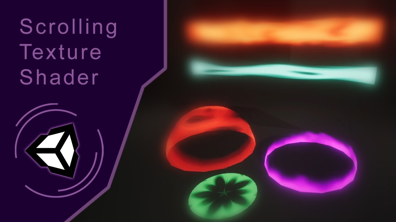
Here's a quick tutorial on how to create a panning texture shader in Unity ShaderGraph. Ask me any question!
Follow me on my socials:
Arstation: https://www.artstation.com/zemasu
Instagram: https://www.instagram.com/mg.zemasu/
Linkedin: https://www.linkedin.com/in/manuelghezzo/
yes but my custom made texture is not moving
show us your shadergraph setup

Why the Vector2 node ?
two decide direction
No
Wrong
You should have put it before the tiling and offset
multiply -> vector2 -> offset
but default particle texture is working

Default particule texture should show a gradient disk
i did't get it
your texture gradient horizontally, but you are scrolling vertically
you should rotate your texture 90 degree using image editor
tbh, I'm not even sure to fully understand what I'm seeing in that last screenshot XD
The UV of the sample node has a constant X value, but the gradient is still horizontal 🤔
The screenshots look all blurry here, I can only guess which is which 😅
But @flat orchid trust and try my maths :
- Time x speed for the scrolling speed
- ↳ Vector2 X or Y (and other component to 0) for the scrolling direction
- ↳ Tiling&Offset offset input to make the UV scroll (and adjust tiling to your need)
- ↳ Sample UV input
still not working for my custom texture
plz show graph, and texture import settings (also please zoom enough in the graph so node names are visible)

Import settings ?
I suspect that it is not tiling

Yep, change the "Wrap Mode" to "Repeat"
nothing happened
Did you apply the import settings ?
yes , ofcourse
Oh, in the graph, you've set the tiling to 0,0 : it is collapsing all the UVS.
Set it to the default 1,1
thanks bro its not working like i want but now i am understanding how texture actually works
I have this weird problem
So I made this simple shader which takes in a RenderTexture, I called it _MainTexOld. The only thing the shader does is return _MainTexOld pixels color + 0.1... I Graphics.Blit it to a RenderTexture I have saved in my c# script and then feed it to the same shader the next frame. So theoretically it should just gradually go from black to white right?
But the screen is just gray, and it does not increment? When I debug.log the pixels color before and after Rendering it, it's just gray?? Anybody have any idea why this is?
My code looks like this (Every frame)
RenderTexture _accuTex;
// _accutex does get initialised I just dont show it

// Prepare shader
ShaderHelper.InitMaterial(accuShader, ref _accuMat);
_accuMat.SetTexture("_MainTexOld", _accuTex);
_accuMat.SetInt("Frames", _frames);

// Render
Graphics.Blit(null, _accuTex, _accuMat);

// Show result
Graphics.Blit(_accuTex, target);
Oh right I will post the code of my shader
sampler2D _MainTexOld;

fixed4 frag (v2f i) : SV_Target
{
  float4 oldRender = tex2D(_MainTexOld, i.uv);
  return oldRender + 0.1;
}
I would avoid using _accuTex as a texture being sampled in the shader (or used as source, which is kinda the same thing here) and the blit destination. According to the blit docs it leads to "undefined behaviour", possibly why it's just grey.
Instead, can use two RenderTextures and swap between them each frame. e.g.
private RenderTexture rt;
private RenderTexture rt2;
// Init (in Start)

// Render (in Update/LateUpdate/FixedUpdate. Also may want to pass Time.deltaTime into a float property, rather than just +0.1)
Graphics.Blit(rt, rt2, blitMaterial, 0);
(rt, rt2) = (rt2, rt); // swap buffers

// Show result
Graphics.Blit(rt2, target);
}
Or can use a CustomRenderTexture object instead with double buffering enabled, but I think that requires a specific shader.
I see! Thank you, I will try that out 😁
Yeah that did it 👍
how do i smooth out the transition of the black border into white?

Can try replicating what the Rectangle node does, but use a Smoothstep instead of dividing by fwidth. https://docs.unity3d.com/Packages/com.unity.shadergraph@12.0/manual/Rectangle-Node.html
Or use box sdf and Smoothstep. https://iquilezles.org/articles/distfunctions2d/
thanks
ok so a potential solution is to put the object on a seperate layer, and then you can put the pixelated camera to only render object on those objects.
but it might be expensive not sure
thats a good question, does anyone know if cameras are super expensive even if you turn the culling mask to only render specific objects, what about if you do something like a single image rendering on the camera, is that expensive?
hhello
rain in the car's headlight is lit, but in the dark area it's not

this is cool and i like it but it only works on the reflected side
viewed from this angle the rain remains dark, what can i do to make the illumination carry through and be visible from this side of the particle?

i have my mat set up like this currently

You could try translucency or transmittance
I was working on that kind of material for URP using custom lighting functions, but it was bit too complicated for me so I shelved it
Custom lighting functions probably aren't a practical option for HDRP
I am adding the keyword _ADDITIONAL_LIGHTS to Shadergraph since I’m using custom lighting. Should I use Shader Feature or Multi Compile? I’m super confused about that 🫠
shaders question
You can make multipass shader (assuming you are using built in, not sure how to do that in urp, sorry)
1st pass, draw the object itself
2nd pass, grab the drawn object
3rd pass, redraw the object with pixelated shader.
Is it expensive? It depends on how big is the object drawn in the screen space, but I've done this for topographic shader and it run well in low end android.
using translucency makes it go green apparently @grizzled bolt

Translucency requires a diffusion profile which if missing will appear green
oo
Refraction is probably a better candidate
this shi so complicated, and yes, im using urp
Ah, you used thin mode. Maybe try the sphere mode, as droplets are basically stretched spheres

By transmittance I meant refraction
Apparently that refers to tinted refractions and absorption
Extreme IOR values will make refractive materials look incorrect
I wouldn't be surprised if 2.5 IOR makes them seem black or solid
it looks alright from the front

Try "realistic" values, like 1.2 for water refraction value, and 1 or 2 mm thickness

Do thos particles have some normal information ?

It would probably help, as since they are currently "flat", they don't bend the light like srops would do
alright, one sec
Also, you might not need to make them fully transparent, maybe a little opacity would make them more visible.
I assume the refraction needs roughness also, since their speed would blur them out in reality
i use this normal

this might be easier if faked using light shaft and multi layered scrolling texture, just saying

Raindrops are also quicker than any ordinary eye or camera can capture, so we expect them to look blurry and smeared when falling
The stretching when the camera move is what bothers me the most here :/
That looks weird for sure, but it seems kind of logical too considering the great relative speed of the camera here


@grizzled bolt :)

this is good but there's one thing i don't get
i'm not sure what is causing the particle lines to get aliased in this way

default resolution rendering helps but they're still aliased
Are they rendered in the low resolution transparent queue ? (shouldn't, else you wouldn't have refraction working)
Also, do you use an opacity mask to shape them, as you have the sphere looking normal texture ?
i removed the normal texture now because i didnt see any effect from it when comparing
i believe the lines also have no texture, they're just white rectangles
it's the default rendering queue here and they are sharper but still aliased

Do you have any form of AA enabled ?
yeah
Have the lines a bit wider with an alpha texture might give you a "free" anti aliasing (texture opacity sampling)

Does anyone know why unity refuses to render this cutout wall in a replacement shader?
The replacement render is at the top and the normal render is a the bottom

I do the replacing with cam.RenderWithShader(depthShader, "RenderType");
The shader has an opaque-only pass and the cutout wall is technically opaque

How can I fill each of these hexagons with a random color?
The hexes are a result of a very long and complicated formula to describe hexagons, but I lack the understanding to find when/where in the huge graph to extract the per hexagon position
I know random color can be generated based on the pixel's position in world space, but how do I fill the hexes with that data to be able to do that?


If each hex was an individual game object it would be trivial to give each a random color based on world position, but because its its a texture, I can't figure out how to isolate 'one hexagon' to pass that data into the random function

how do I get filled hexagons instead of gradient hexagons based on world position out of this?
if I had solid color filled hexagons filled with a greyscale float where each hex was its rounded hexagonal position in world space nearest to the center of the hex it would be easy to get random colors, but I don't have that, I have hexes filled with gradients which is of no value to me

Observable
If we have points in a hexagon grid represented using “axial coordinates” – and coordinates aligned with two grid axes oriented 1/6 turn (60°) apart – we can round to the nearest hexagon with the pseudocode below: def axial_round(x, y):
xgrid = round(x); ygrid = round(y)
x -= xgrid; y -= ygrid # remainder
if abs(x) >= abs(y):
...
the answer is somewhere on this page
but its 1000000000000000000000000000% WAY too programmer, I cannot make any sense of this, its frustrating to know the answer is buried in this incomprehensible gibberish but im too stupid to find and extract it
use chatgpt
seriously, I've used it actually when reading some graphics ressarch papers to help translate math equations to code, or even using it to translate from one programming language to another
give it a shot
<@&502884371011731486> @prime pivot nitro links bot
ive tried, i cant find words to make it understand what i want
that page is not condusive to copy paste, if you try to make selections youll see it doesnt go into the text boxes of code
i know what i want visually, i cannot describe to gpt what i have and how to get what i want from what i have because im just cant
for reasons im not allowed to say
Does anyone have any general tips on how to speed this up? I'm not sure what I'm doing that's causing it to be so slow except just having large amounts of code. Any ideas what kind of things to look out for or try to avoid? I'm doing some raytracing so there's a couple of for loops i'm calling as a method in a bunch of places for one which seems to be a huge culprit. Is it bad to have large amounts of globals or is it better to define them locally?

When the Standard shader is set to Cutout, it changes the RenderType to TransparentCutout, so your replacement shader has to have a pass with that tag.
I already figured it out, but thanks
I looked up the source code for the shaders and couldn't find the TransparentCutout part so I just assumed cutout used the Opaque tag
an example of how it just doesnt get it

I cant seem to find the language to explain to it what I am trying to do, no matter how simple or complex it doesnt understand
another insane sollution that is way off the mark

How do I get random filled cells from what I have on the left?


if your not able to get it to work then I would abandon chatgpt and jus tkeeping asking here
Yeah thats what I am doing as we speak 
my cells have no concept of world position, but I can't just add the world position to them because I don't want gradients in the cells, the cell must be entirely one single value across its entire face
but I dont know how to derive that

as it stands im plugging nodes into nodes with zero comprehension
and that will never result in what I need
so all I can do is ask for help
because I'm too inexperienced to know the answer, and too stupid to find the answer
all I can do is ask
its a struggle to even visualize if it working or not


part that confuses me is that my hexagons are a float
but coordinates are XY
but colors are Vec3
but I dont understand any kind of math to go from 1 to 2 to 3
the closer I get to a filled hexagon, it just turns into a solid wall of white, its not a hexagon at all

I cant even explain it to gpt I'm that clueless
how is that not a hexagon?
its not a hexagon in the way I need it to be

I need this
this is what I want
I dont need anything else, I dont want to argue or fight, I just want results
so random colors or what?
Yes, every cell to have a random color completely filling the entire cell
getting random colors is easy
filling hexagonal shaped cells is not
I dont know how to create that
you said something about checking each hexagon using world position?
there is no other way to fill each cell with a random color to my knowledge
you need some value to create the randomness
use uvs instead
sure, literally nothing changes between XY in uv space and XY in world space
doesnt get me any closer
yes it does, if you are implying that they are equivalent then...?
No it doesnt and I dont know why you are fighting me on this
is this how you generate the hexagon tiles?
yes
I cannot see the full extend of your code
has anyone attempted to create a shimmer effect for 3d textmeshpro?
no diffrence between uv and world space


let me get you that
not fighting, just eaying that they are not the same
you are fighting me by insisting they are not the same because its important to you that you be correct, when for all practical and functional purpose they are the same. They are a vector 2 of values that range
can I also see what one hexagon so untilles looks like?


There isn't a concept of one hexagon
or if t there is, I dont know how to get it
the hexagon only comes into existence at the vector 3 in this image, at every step before this is all squares

anyone?
I'm really sure there is a solution as for squares you would just divide x or y by the square size and you would have the square coordinate
I dont want squares, I want hexagons
here is my shader in its current state because I'm going to go take a shower and make dinner to clear my head
and I feel lik showing pictures is useless when I can just share the shader itself
we know what you want let us think
possibly stupid idea incoming, but whatever: as long as you know the maximum width/height of your hexagon you should be able to check what hexagon we are currently prossesing by checking how many hexagons fit into the coordinates we currently have if its the same amount we use the same color if its another amount we use another color. (no garantie of this theory, i haven't checked it mathematically, just logical thinking here)
this is my randommization function/subgraph, but it only works if the hexagon's entire surface is all the same value


Hi all. I'm pretty new to Unity, and I am just looking for some advice about an effect. I have a shield sprite for a 2D spaceship, and I want the shield to appear from the center out on input from the user. Is using a shader the best way to do that? If so, would you be so kind as to point me toward the nearest bone?
a shader can do that fairly easily. Something like this should get you started

set the Reference value to something sane and then use that to assign to the value in code to animate your shield growing out


more shader stuff today
i want to make snow based on the normal
this is my snow lerp:

how can i
a) make it interpolate the normal direction between verts
b) make it incorporate the normal map texture into the calculation?

what do you mean with a
so the amount of shading is based on the surface normal and you can see in the picture that this is different for each polygon, so they have hard edges
but this is not being caused by split normals in the mesh
i want the shader to be smooth
a) I could be wrong but I think this has to be done in the model itself - either in the modeling software or if it's procedurally generated in the code (search for "smooth shading")
b) blend normal node should do the trick - blend between the mesh's normal (that you're already using) and the normal map (you'll have to define a new exposed texture of type normal map)
here's what my modelling is showing me: it seems to be using combined normals

in unity also the import settings uses 'import' and not calculate

so i don't think it should be changing them
finally here's when using a shader not made by me

so it's definitely my shader's fault i think but im not sure how to fix it, do you have any ideas?
for b, perfectt, thank you :)
Unity docs say the "Normals" and "Blend Shape Normals" import settings should match, try setting both to "Calculate"
alright
hmm that didn't seem to change anything yet
whoa? i fixed it but uhh i don't know how
i was messing with the normal blending of a different part of the shader and that had an effect here too as u see

@tight phoenix If you're not getting what you want with the full nodes setup, may I suggest to maybe throw it away in favor to simply using a texture for the hexagons ?
You have 4 channels to store information, and from what I understand you might need only 2 or 3 to do what you want :
- one to store a gradient "shape" (distance field) of the hexagons to draw them
- one or two to store the UV relative coordinates of the center of each hexagon -> you could then use this as source for the random color
@arctic flame To use also the info from the normal map, you can :
Sample the normal map as usual -> use the transform node to transform the value as Direction from Tangent to World space.
Oh, and unless you want to tilt how the snow it applied, if it's straight from the top, just get the Y value for the normal, no need for dot 🙂
oh, you're right! good thinking
Can you describe a bit more your setup here ?
The default shader should not look like this
wdym ?
how do I use cubemap in shader graph? for some reason it looks like this

graph itself

I think it's something to do with the graph settings but I'm not sure what
Sometimes skyboxes seem to work despite the error "shader of this material does not support skybox rendering"
Had luck fixing it with these settings

worked with transparent only for some reason
or wait
now it works with opaque
🤔
mystery
is there any way I can apply fog on skybox?
The warning, the problem and the solutions online are all pretty arcane
for specific height only
You can sample scene fog color with Fog node, and then lerp a specific height of the skybox to that color
I'm not really following lerp specific height part
Using a height gradient such as this

You can get the height
Lerp your skybox color to your fog color using the gradient as the T
Before that step you can shape the gradient using multiplication, addition, power, gradient sampling or any math that helps
ok, so I have this remap part (blindly followed from tutorial)
I have fog node
how can I simply have alpha value per height with it?
The gradient is your "alpha" via the lerping
oh, I think I start to get it

now I'm not sure how to define specific height
where it starts gradient
and where it ends it
From the lowest point of the sky to the highest point
I mean in graph
rn I have it so gradient is applied globally
from lowest point to highest
I want it to apply on specific height
basically define horizone, where fog ends
That's what I mean by using the gradient as the T of the lerp
lerp of what values though?
You blend between A your sky and B fog color using T your gradient as the lerp factor
What do you mean by "dynamically"?
where height can be defined in material
Yes, for example by making properties of the remap's inputs
If you modify the Remap inputs by a lot you'll want to add a Saturate node after it so you won't be lerping with values below 0 or above 1

somebody knows how to make a collider for a vertex shader?
Not possible.
You need to deform the collider mesh using the c# mesh API
how do materials work for shaders?
is there a better way to do this?

(mainly the offset)
i was thinking of splitting the RGB channels and then offsetting those but that just doesn't seem to work
so i have ot sample 3 times
which i feel is unneccessary
This is a Uniform chromatic aberration shader that i somehow managed to make as my first shader
(I am in unity 2021.3.22f1 using URP)
A material hold the properties values for a shader : You can assign the same shader to multiple materials, and change the properties for each of them to change the look and behaviour of the shader
Indeed, the only way to do is how you did it : sample 3 times the texture
how can i assign a shader to a material?
It's the topmost setting on any material :

oh right
after making the shader and assigning it to a material, how can i control it from a script (for example if the shader should be active or not)
What do you mean by having the shader active or not ?
Else, you can modify the material properties from script using the material API : https://docs.unity3d.com/ScriptReference/Material.html
from my understanding i can do inside of my script Graphics.Blit and passing into it the shader material if i want the effects of the shader to be seen or just do Graphic.Blit and pass the source and target texture untouched if i don't
it's just that it isn't working for me
Oh, so you're using the shader in a blit. Ok
What is "not working" ?
I'll send the code give me one sec so i can explain better
If i put this script in my main camera, assign to shaderMaterial the material that has the shader attached and edit boolean while the scene is on play nothing changes
private void OnRenderImage(RenderTexture src, RenderTexture target) { if(boolean) { shaderMaterial.SetTexture("_MainTex", src); Graphics.Blit(null, target, shaderMaterial); } else { Graphics.Blit(src, target); } }
boolean in this case should be a serialized bool
What render pipeline is this in?
Graphics.Blit(null, target, shaderMaterial);
Look at the doc :
Passes source to the mat material as the _MainTex property.
So you are passing null as _MainText : the SetTexture line is useless.
And like Cyan pointed out, OnRenderImage is not supported in SRPs
URP
Then yeah, OnRenderImage is not supported. You'd likely want to use a Renderer Feature instead. e.g. https://github.com/Cyanilux/URP_BlitRenderFeature
Or if you're in 2022.2+ there's also a Fullscreen Graph & Fullscreen Pass Renderer Feature. https://docs.unity3d.com/Packages/com.unity.render-pipelines.universal@14.0/manual/post-processing/post-processing-custom-effect-low-code.html
so should i use HDRP?
If you are a beginer, I suggest URP
No, OnRenderImage isn't supported in HDRP either. I just explained alternatives
then when is it supported
Built-in render pipeline
Never
An other API or way to do the post process was introduced with SRPs
i already feel comfortable with shaders, i just don't get how to set up them for unity
so when making a new project i should use this?

Yes
If you're so set on using OnRenderImage specifically, sure
is this unnecessary?

(is having the simple noise output into a vector2 slot going to duplicate the channels by default?)
Yes, by default casting a float into vector2 will set the value in the two channels
is there toon terrain shader for unity urp?
i know in unity srp there is a toon terrain shader
like how to achieve this kind of look in unity urp

in unity terrain
rest i have already done it
is it possible to ask unity to arrange this?

how do you turn a rgb into a texture in shader graph?
wdym?
Shader Graph can't do that, you'd need to arrange manually. Adding groups around some nodes can help with organising. You can also collapse some nodes to make them smaller
oh that
You don't
oh ok
are you intending to create a texture?
or modifying a texture?
creating a texture. i got a custom function to blur a texture but i have a rgb
How can I make my a spotlight cut through fog?
That's usually up to your render pipeline's type of sepcific fog
what do you want to blur on an rgb value
there's nothing to blur it with
ty
you're modifying a texture by blurring it though, no?

what render pipeline are you using?
How do I check it
@grand jolt
Does anyone know whether it is possible to get BIRP shader graphs to work on Quest 2? It doesn't seem to work even with the very simplest shader. EDIT: the solution was going into unity's CGincludes and ripping out the relevant section. I don't love that, but it works.
Getting undeclared identifier 'UNITY_DISPLAY_ORIENTATION_PRETRANSFORM' at /2022.1.0b8/Editor/Data/CGIncludes/UnityCG.cginc(813) (on vulkan) whether or not I actually use Vulkan. This is both with and without "Apply display rotation during rendering" in the Vulkan section of Player Settings.

It appears im not using a render pipeline and when I go to create one I dont see the "rendering" option under "create"
i have this shader for getting vertex color + alpha. it works for parts with proper vertex alpha but also screws with parts that are fully opaque like this doorway, any ideas how to fix this?


Is there a way to have like a dissolve effect on a model affect all its submeshes?
Are they using the same material?
Nope. The mesh typically has a body, mouth, and eye material, and they use shaders that deal with image arrays.
It is a transparent material, so it isn't depth sorted.
So you'd need to either pass the same dissolve parameter to each shader, or render the object and all submeshes to a render texture and dissolve that.
So, if I were to take the RenderTexture approach, I could use a secondary object to dissolve the model as I see fit, correct?
[Like, a model with a special shader can basically mask out the render texture, right?]
[I'm using built-in]
Then in that case you can use stencil buffer for masking.
And if some objects have transparent geometry, that'll cause problems, right?
So, I can configure the shader so it can decide if it writes to the stencil buffer or not?
Correct.
Haha, finally got it to build with no errors https://i.imgur.com/jBOXRr9.mp4
Really cool is this using VATs or what did you use to achieve this ?
Similar idea with baked pivots, though I am animating them procedurally.
Interesting. Care to elaborate on the baked pivots part? How does the texture work? @pulsar kelp
Aw man... I wish I had the brains to do that stuff...
why does this not move the maintex texture?

like transform it
it does not move at all
the output wire is going out to the fragment color
holy shit i am so stupid i haven't connected the animated UV but the static one 😭
holy crap shaders are so cool

There is no actual texture for this one; you could bake the pivots to a texture basically the same way but I used the UV channels of the mesh itself, which lets you reuse the same material for multiple meshes.
This article gives a pretty good overview of the concept.
Uses a shader which displaces (scales/rotates) vertices of a prefractured mesh with pivots baked into UV maps
Ok but how does the actual data look like? How do you group vertices by a pivot ? Im just interested in how the technique generally works. If you have some links about it that would be great.
Ah perfect
My version is a bit different, since he's using normalized uv values, but the basic idea is the same.
Oh its from Cyan ofc
Yeah, you can learn a lot of good stuff from him. 😄
My method of baking is somewhat different since I'm not using blender
That's all you need to bake pivots in houdini. The biggest difference is that you don't need to remap the pivots from 0 ,1 to -1 ,1 . You still need to invert the x. Like he says, that could be fixed by fiddling with the baking, too.


Just multiply the vertex positions.
I put too much time fiddling with vertex colors instead of UVs, but that was a pretty big dead end.
Vertex textures work basically the same way, except that it is stored as a texture.
Hey I used a position node to make a flag wave, and when I hit play it moves my flag off of the pole and to a spot far away from where it should be, is there a way to fix that?
How do you have it set up?
Like this

(Unfortunately, no I could not have just taken a screenshot lol)
Was that directed at me?
Hi does anyone know how to create a shine/light sweep effect on 3D object using shader graph? I've been trying to do it for last 2 hours but couldn't achieve it, i've tried using a rectangle, rotate it and move it bottom left to up right and only make the pixels within the rectangle range glow but failed with it since my texture doesn't go from left to right in 3D world, it's scattered and packed on islands like many textures
i thought about using the position instead of the texture but i don't know how to rotate it 45 degrees to look like a light sweep
something writing to depth when it shouldn't be
It looks like you should just be using alpha clipping, which can write to depth just fine, there's no need for true transparency here is there, everything looks to be transparent or not, no half-way
I have no idea how you made this material in the first place
yes, but is this your own shader? Or are you using a built-in material, what is it?
Expose a value like _Cutoff ("Alpha Cutoff", Range(0, 1)) = 0.5 so you have a slider to control the cutoff,
make sure you declare it float _Cutoff;
and then put this at the end of your fragment block
clip(color.a - _Cutoff); (with your alpha replacing the obvious)
it makes it so anything below the cutoff value is below 0, which the clip function interprets as completely transparent or not
seeing as it's interpreted as completely transparent, it shouldn't write to depth
You aren't actually making use of the original z position of the vertex, so it will always be the sine output times the U. You are replacing the position instead of offsetting it.
Thank you! Any idea how to fix it?
The outline is probably from the RGB channels :
Force RGB to a single color and only use alpha for masking, you should be good
yeah, the outline is because in the image the color fades to black before the alpha reaches the cutoff threshold
I guess you would wanna make it a bit thicker? 🙂
Looks like you basically want an opaque with cutout
Usually +, but that depends on the BlendOp. https://docs.unity3d.com/Manual/SL-BlendOp.html
(Add is the default)
i managed to make my shader work with Graphics.Blit but is there a way to make it work in the scene view too?
not by default, but this guy has made a script (its in the description for download) which should apply the blit to the scene view as well

Welcome to the 'Raymarching Shader' tutorial!
Scene View Filter download link: https://www.patreon.com/posts/23512446
I'm super excited to share this video with you all. It took me a couple of months of research into the subject, and many days to create this video,...
If you do not set a destination in the blit command, it should render to the screen.
https://docs.unity3d.com/ScriptReference/Graphics.Blit.html
To blit to the screen in the Built-in Render Pipeline, follow these steps:
Set dest to null. Unity now uses Camera.main.targetTexture as the destination texture.
Set the Camera.targetTexture property of Camera.main to null.
I'm trying to fix a little quirk in my volumetric ray-marching tornado shader. When the camera enters the volume the tornado is being rendered in, the transparency of the funnel increases:


(left: outside, right: inside)
I calculate the ray-box intersection, and start the raymarching from there. The step size is set to distance inside box / number of ray marching steps
I'm not sure if it's a ray marching, or blend mode issue
Is there such a thing as "extending a shader"?
I have this built in unity toon shader package, and I wanted to add things to it
but I don't want to need to figure out how this black magic work, just, do extra things after it
do I need to make a copy of it and modify the copy or there is some way to add stuff before/after the shader passes like it was a c# class?
Nope, copy and modify is the way
how do you rotate a UV?
figured it out

that was obvious
how can i get a discreet time output, like 10, 20, 30?
i started messing with shaders yesterday
im very new
Time -> floor -> multiply by 10
ooo
yeah that makes sense
ty :D
yay i made a glitch effect now
does anyone know why the shadow is bugging?
aaa
const float2 s = float2(1, 1.7320508); // 1.7320508 = sqrt(3)

float3 hue( float c )
{
    return smoothstep(0.,1., abs(fmod(c*6.+float3(0,4,2), 6.)-3.)-1.);
}

float random(float2 co)
{
    return frac(sin(dot(co.xy ,float2(12.9898,78.233))) * 43758.5453);
}

// xy - offset from nearest hex center
// zw - unique ID of hexagon
float4 calcHexInfo(float2 uv)
{
    float4 hexCenter = round(float4(uv, uv - float2(.5, 1.)) / s.xyxy);
    float4 offset = float4(uv - hexCenter.xy * s, uv - (hexCenter.zw + .5) * s);
    return dot(offset.xy, offset.xy) < dot(offset.zw, offset.zw) ? float4(offset.xy, hexCenter.xy) : float4(offset.zw, hexCenter.zw);
}

void mainImage_float(float2 fragCoord,  out float4 fragColor)
{
    fragColor = (0,0,0,0);
    //float2 uv = (2. * fragCoord - _ScreenParams.xy) / _ScreenParams.y;
    float2 uv = fragCoord;
    const float tileAmount = 3;
    float4 hexInfo = calcHexInfo(uv * tileAmount);
    fragColor.rgb = hue(random(hexInfo.zw));
}```

I am trying to port a shader from Shadertoy to HLSL.
I've gotten to the point where it doesnt throw an error, but the resulting shader is pure black.
What is wrong with this code?I fixed alpha to be 1 instead of 0 but its still pure black

this is the code im trying to convert
is fragCoord normalized?
Should it be? Right now I am passing in UV for that value
this is all I am doing, I plan to make it do what I want later, I just want it to show anything at all to begin with

Normalizing it first made no difference
i couldn't help you im a noob ¯_(ツ)_/¯
You may need to add static at the very beginning to the s variable. By default, values in the outer scope are set externally so default to 0 even if you try to initialise.

Ah yes I came to the same conclusion, s was not a thing, manually replacing it worked
Ill try reverting and adding static to see if it makes a difference
I'd also be a bit careful with converting mod to fmod as they deal with negative values differently. Might be okay here though.
https://www.cyanilux.com/faq/#glsl-mod
Ooh interesting, thank you for the insight. Going to try to move as much of this shader out of the custom and into nodes now that it does render
Still looking for answers
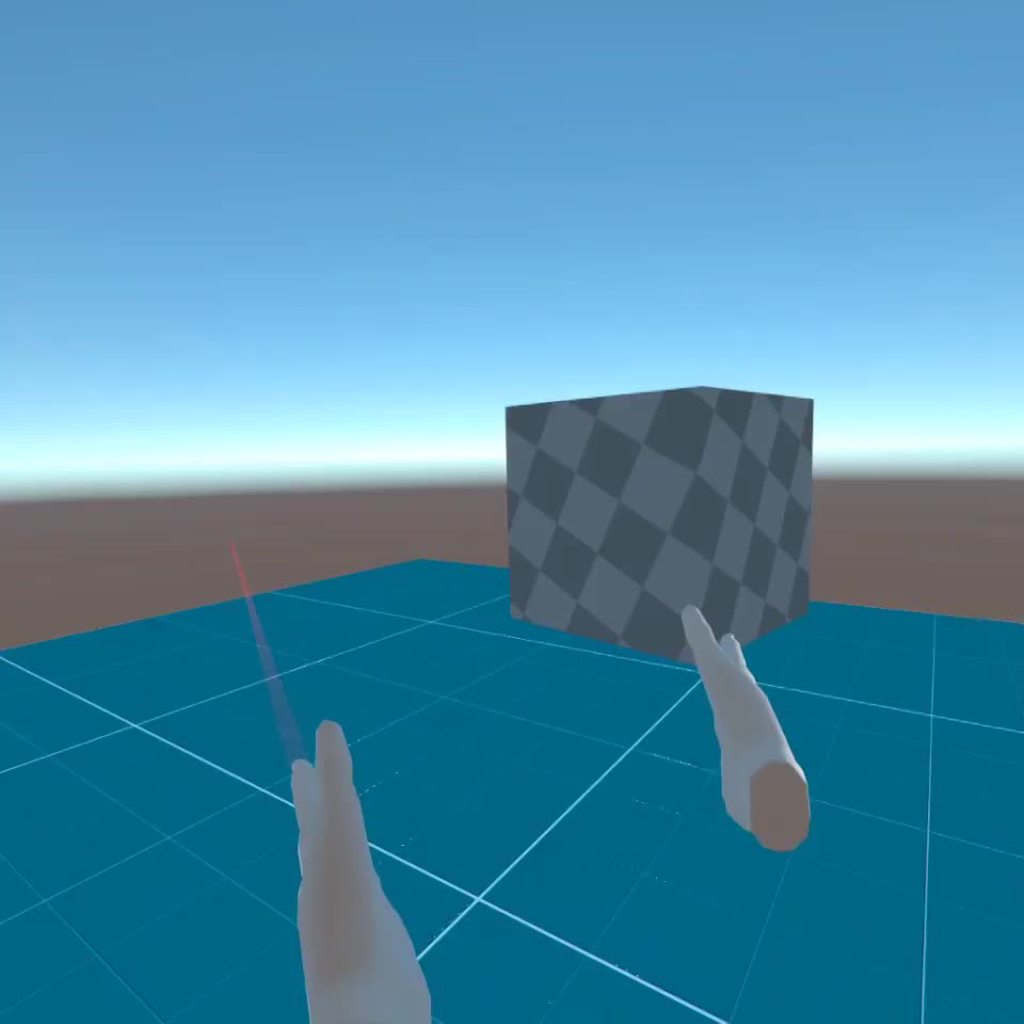
if i wanted to blur everything behind that box, how would i go about doing that?

would it be possible by adding a shadergraph material to that
but how would i get the display texture behind the material to blur it
Like it was already answered :
You are replacing the position instead of offsetting it.
You can use a transparent unlit shadergraph, and the scene depth node to grab the content of the screen.
However : it doesn't support LOD on URP, so no easy blur, and you will have to do a blur yourself, like a simple box blur.
And it will not do it only for what is behind the box, but "everything that is on screen and was rendered before" => all the opaque objects
what about the UI, would it blur that too?
Yes, that does explain why it’s happening, but I don’t know how to fix it
Offset, do not replace :
- You are setting the Z position, instead of adding the wave motion value to the current one
- insert an ADD node between combine and multiply, other input is SPLIT.z
If UI is drawn as "ScreenSpace - Overlay", no
hello everyone! i created a basic room in blender with shaders and all and im wondering how do I carry it to unity? When I use the fbx file it dosent really carry over with the shaders. Im new to 3d 😅

Yes
noo but i want my post processing to happen on there too
Thank you! I’ll try this when I get home!
Unity can't import blender shader nodes, you will have either to :
- re-create the same node setup in unity with shadergraph / amplify
- Bake the textures to "regular" blender materials with UV mapping

Then world space canvas is ok, but all the sprites there would need to be rendered as opaque (with cutoff), they are rendered as transparent by default, and I'm not sure it is possible to change it without using a custom sprite/UI shader
that makes sense, are the nodes similar to blender or would I have to learn some stuff?
they are
somewhat
but what about the blur then
if it's opaque
i see
Is there a point to explicitly avoid using "if" in shaders?
Sure the if only ever helps if all cores are in the same branch, but that at least has a chance of happening, meanwhile a massive piece of code that at the end enables/disables it with a 'lerp' sounds much worse than simply using "if"
Am I just wrong about how it works?
probabbly not
but it can decrease performance and efficiency
lerping is generally faster
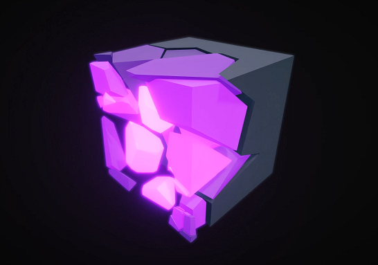
Guys I am fascinated by this fracture shader, I want to replicate it but I need some keywords, can anyone help?
https://youtu.be/iYrAevFK8sE?t=7945

SODA CRISIS Full Game Gameplay Walkthrough Longplay on PC RTX 3090 with No Commentary and in 4K 60FPS.
► Rubhen925 is a Gaming Channel that makes gameplay videos focusing on a Walkthrough, Playthrough, Full Game runs, Boss Fight, All Bosses, Cutscene, All Cutscenes, Ending, Endings, Compilations, Showcases & Guides for games new & old with No C...
I know the fundamentals of vert and frag shader
There's a lot of misinformation and they aren't that bad, especially if it's a property that won't change per-pixel. Also, using an if doesn't even mean it'll branch - the compiler is pretty clever about it, but you can also specify [branch] or [flatten] to try to force either. Can always try both and profile, see what performs better.
Also do need to be careful when sampling textures. This article mentions using LOD or GRAD versions : https://medium.com/@jasonbooth_86226/branching-on-a-gpu-18bfc83694f2
Can look into "Pivot Baking". I also did a similar effect + breakdown recently (but "strength" is inverted compared to that video, can use One Minus or swap edge inputs on Smoothstep)
https://www.cyanilux.com/tutorials/fractured-cube-breakdown/
Uses a shader which displaces (scales/rotates) vertices of a prefractured mesh with pivots baked into UV maps
I will go through this thank you
is it possible to get the colors of the screen behind the object i have the shader on?

Assuming the shader is set to Transparent and the Opaque Texture is enabled on the URP asset, can use that Scene Color node
It'll only contain opaque geometry that is though
If you need to grab the screen at a different point in URP, can use a feature to blit the screen to your own render texture.
e.g. https://github.com/Cyanilux/URP_BlitRenderFeature (source : camera, destination : texture ID. Can then sample in shader/graph using Texture2D property with reference set to that texture ID.
(But then you need to render your shader/object with the RenderObjects feature to force it to occur after that blit)
If you're using Built-in target / render pipeline... not sure. Can probably do something similar using Graphics.Blit. Or code a shader manually and use GrabPass.
I am using URP, what is a Texture ID?
i already have used the blit feature to do some post processing
Just a random string basically. It'll be the same reference you want to get the texture later
hmm
As a global Texture2D that is. In shader graph would need to untick "exposed" on the property
I have this


and this
but

Change the graph to be unlit and use _MainTex instead
that shadergraph
is from another normal material
it's not the same material that's being blit
Oh okay, but the Passthrough material is using one with _MainTex?
The Blit Material on the feature
yeah that is just a generic material because i didn't know what to put there
and it was giving me warnings if i left it empty
It needs to be a unlit material that samples _MainTex and just outputs it. It's there because the feature can also apply shaders for image effects / post processing, but in this case you probably just want to copy the texture as-is

How do I set a custom shader to additive or multiply, blend modes that something like URP/Particles/Unlit has?

it just renders normally
Ah okay found it in here

my shader was opaque that is why I couldnt find it, needed to be transparent
okay, i've setup the passthrough material

this is extremely odd

the material
displays the preview icon for the selected material in my assets folder???!!!


wow this is strange
only seems to happen for textures
Yeah that's a bit odd. I guess the feature is running in previews too, not really intentional.
it seems to be affected by my mouse cursor position, selected file and a bunch of random things, without the game running
this is the shader for the square

it feels like it's reading memory that it shouldn't be
I haven't had this problem before, but may need to add if(renderingData.cameraData.cameraType == CameraType.Preview) return; into the Execute method in the Blit.cs script

okay
i just realised you made this 😱 that's so cool!!
the extra line did not do anything

Ahhh

it was because i had the material on a UI element, i changed it to a sprite renderer

It looks like it's rendering to itself which isn't really good. You need to make sure that quad gets rendered after the blit occurs rather than before
Should be able to do that using the RenderObjects feature.
Can put the quad/sprite on a layer, remove that layer from the Transparent Layer Mask at the top of the Universal Renderer asset, and add a RenderObjects feature filtered to that layer with Event set to something after whatever event is on the blit one

the flickering doesn't happen in play mode
i missed this part "remove that layer from the Transparent Layer Mask at the top of the Universal Renderer asset"
i can't find it
The asset is the same thing you add the render features to
yes i know that but
i just cannot find the "Transparent Layer Mask"
I'm running 2D renderer
with URP and unity 2021


I guess it doesn't have it. I'm not sure how to set it up for the 2D Renderer, might not be possible 🤷
hmm would using multiple renderers be possible?
Not sure. Probably not recommended though. But maybe using camera stacking with 2 x 2D Renderers would work? Have the first one handle the blit, and a second empty one. Use culling mask on cameras to only render the quad on the second one. Not really sure
i see what you mean
You know, surely it cannot be that hard to blur a part of the screen
can it?
(it can)
the beauty of the scriptable render pipeline :)
😭
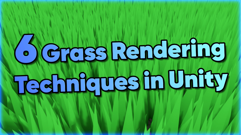
The first will be easier on the GPU, but potentially more CPU heavy if you use that for rotation.
The static version in the screenshot will look a LOT better however. Especially if you stand above it it won't flatten out
https://danielilett.com/2022-12-05-tut6-2-six-grass-techniques/
https://www.youtube.com/playlist?list=PLUKV95Q13e_U7nZFPIpiG9-z_3BdWcCOA
Some good sources

YouTube
The point is that "object space" doesn't really exist if batching is combining meshes
But I imagine billboarding is still possible if you use GPU instancing
i created this water color shader in blender which gives my models a water colorish look, would i be able to do something similar in unity? If yes , would someone help me with the process 😅

how can i make shader, that will gradient my text from left to right infinitely?

Create a smooth animated gradient text effect in Adobe Premiere.
Learn video production, editing, and more at 'Brooker Films Video Creator Academy':
https://www.bfvca.com
» Video Production Pro: Learn how to film amazing videos.
https://www.bfvca.com/videoproduction
MUSIC
The music in this video was supplied by Epidemic Sound: http://share.e...
something like that in 3:52
im using text mesh pro as my text
Yep, lerp the color based on the position and use time with sine waves to repeat it
Not sure how it integrates with text
i just dont understand how can i put it like on that text
because i can't see anywhere a slot for a material on text mesh pro
@rare wren
You can change the shader on the text asset. Probably need to add alpha clipping so it looks sharp.
Googling 'unity text shader graph' also helps probably. You could also look into the tmpro shaders and/or having the text as texture with a custom shader on it


but that'll change the shader for that material
and im using this material for many texts
and just want the gradient on this particular one
and disable the shader conditionally
i can just copy the material ig
Then duplicate the text asset?
i need further explanation as im just starting with shaders :/
so i've created an unlit urp shader graph @rare wren

assigned it to the material, and assigned the material to the text
and this is the outcome
this is my graph, did not just but reduced the alpha to 50%

i just want to be able to see this text with my custom shader, then i'll figure it out how to make a scrolling gradient
this is probably not that easy with a text :/
Not very easy as there doesn't seem to be documentation for it
You'd have to use the exact same properties in your SG as TMP does in their shader, and replicate the font rendering features you need in it too
is there any work around such as making like an Image over that texxt
with some alpha
or just an image with that text instead of the text
that gradients, would be easier i think? @grizzled bolt
Sure yes, if you have your text stored as a simple texture you won't need to worry about any of that
i just realized that might not work
as i have localizations in my game (translations)
so will need each image for each language and enable them based on the language
there must be a simplier way just to put the gradient on the text
and make it scroll horionztally lol
From what I hear the Localization package handles any kind of asset
Whether it saves you effort or not to make a custom TMP shader will depend on how difficult that turns out to be
Maybe all it requires might be to find the font texture reference
I'd google around for examples in case there's some
okay so this is what i managed to do

im trying to do that on a Image
and it seems to work but in game it looks like this

tho this little visible piece is blending fine
now questions, how can i make the gradient scroll horizontally instead of gradienting the whole image
There's probably many tutorials for that
there none i could find
are you using urp or hdrp?
Urp
alright you should just be able to create a shadergraph that does the same thing as your blender shader
oh okay I'm not at home right now would you mind guiding me how to do it when I'm back home
if you're okay with that , that is
well the nodes are fairly similar
probably not the same names always but it should be easy to figure out if you know what they do in blender
alright i will try it , thank you
also, if you cant figure something out, you can ask about a specific part of your shader and how to convert it
alright , thanks for the help . I will let you know if i face any issues 😀
There's no equivalent in Unity for "shader to RGB"
But the rest of it should be okay
what does that one do though
Sums up the shading result to a color output, for example to make a toon shader that includes all incoming light
anyone can link a tutorial for horizontal scrolling gradient shader on an image
literally there is none
how can i make this edge to blend aswell instead of being that roughly cutted color


In blender i have baked the material map, and I want to import the model with the texture to unity, I have downloaded the unity graph editor and done this. My question is how to allign the objects uv map to unity. Bc, as you can se the UV - alligment is wrong(the third pic),Thanks!


Does the object in blender look good with the baked texture applied ?
Ooh, apparently not, you have any clue why?

Do you maybe need to input the UV coordinates to the node here ?
Does the object UVs match what you have in the baked map ?
hey i made a triplanar shader for my terrain at least i tried - is it possible to add the material with the shader on the terrain?
Yep, assign to a material, and assign the material to the terrain in the terrain settings
thanks#
wierd, that it's not working

what is the formula to make two values relative to eachother?
R increases the radius, Add also increases the radius but also makes it more rounded
I want to control the roundedness without increasing its radius, but every combination of two floats and math hasnt given me that result

I know logically that radius must strink when Add increases to offset the grown size, but I havent been able to make that work
Multiple UV maps ?
Previews show the raw RGB data without transparency. Colours are typically stretched out like that in fully transparent areas to avoid artifacts. If you use the A output that's usually not a problem.
Shouldn't it be something like ? :
d =>
r = 1+d
add B input = 1-d
Getting close, the only part of this that bugs me is that the effect gets more rounded when adjusting the size, trying your formula now

Use the UV node, split take X. Add Time. If you want the gradient to repeat smoothly, use a Sine or Triangle Wave node. Can then apply colour with a Lerp, or Sample Gradient/Texture2D

i did it like this and it seems to work just fine
thank you tho i will try your approach aswell
@tight phoenix
Or maybe to have more clear variables, if you want to have a rounded hexagon (what I seem to understand ?) :
Inputs : final radius & roundness
r = final radius - roundness
then subtract roundness from the SDF result
I fixed it now the uv map is correct in blender, but the uv map still look likes this in unity -

got there 👀 this arangement lets me control radius without affecting roundness, and roundness without increasing radius

@tight phoenix If you feel adventurous, you can take the code from the rounded polygon node : Under the hood it is doing a sort of SDF, but you can control the % of chamfer for each edge
I' am an idiot, it's was a really dumb problem, I fixed it, but thank you very much anyway
so i have this "broken glass" effect, although it doesn't look very convincing that it's broken glass, do you guys have any suggestions?

i think the biggest problem is that I don't see any glass, if what you want to create is a broken glass
well i mean like a screen effect
like the refraction of a broken screen
like this

but with refraction
anyways nevermind that but
i have this set to foreground, so Background, Default and Foreground are rendered to _CameraSortingLayersTexture

these are my sorting layers

i have this sprite on the layer which isn't supposed to be rendered to _CameraSortingLayersTexture

i have _CameraSortingLayersTexture property in my shadergraph for BlurMaterial

and i am simply rendering it back into the sprite

the sprite is gray

I've never been so stuck
nvm i have but it's still hard
what am i doing wrong
I just changed the shader for the blur to be Sprite Lit now it is rendered as black
I'm having problems reading from StructuredBuffer in my shader
I set up one and gave it an array without a problem, when reading from it and trying to output to screen its information i get a black screen even though the array it's not a vector of 0
i made an example of what my code looks like for the part i'm having problems with
C# code
`private ComputeBuffer buffer;
void Start(){
Vector4[] colors = new Vector4[length];
colors[0] = new Vector4(1.0f, 0.0f, 0.0f, 1.0f);
buffer = new ComputeBuffer(length, sizeOf(float) * 4);
buffer.SetData(colors);
shaderMaterial.SetBuffer("colors", colors);
}`
Shader code
`StructuredBuffer<float4> colors;
fixed4 frag(v2f i) : SV_Target{
return colors[0];
}`
I am having some difficulty with blend modes, I am working on a shoreline shader but I'm getting unwanted behaviour when things approach each other.
What I would like to see is blending similar to Minimum or Maximum, but I can only select Alpha, Additive, PreMultiply, and Multiply.
Is there a method to have it blend differently? I tried asking GPT but it had no clue, google the same


in a handwritten shader you'd do stuff like 'Blend DstColor OneMinusSrcAlpha' but I cant seem to find the equivalent
the xy end goal sollution I am seeking is for the black mask to exist around each object, exactly perfectly, without any kind of build up like its doing in the above - equivalent of minimum (or maximum?) blend mode

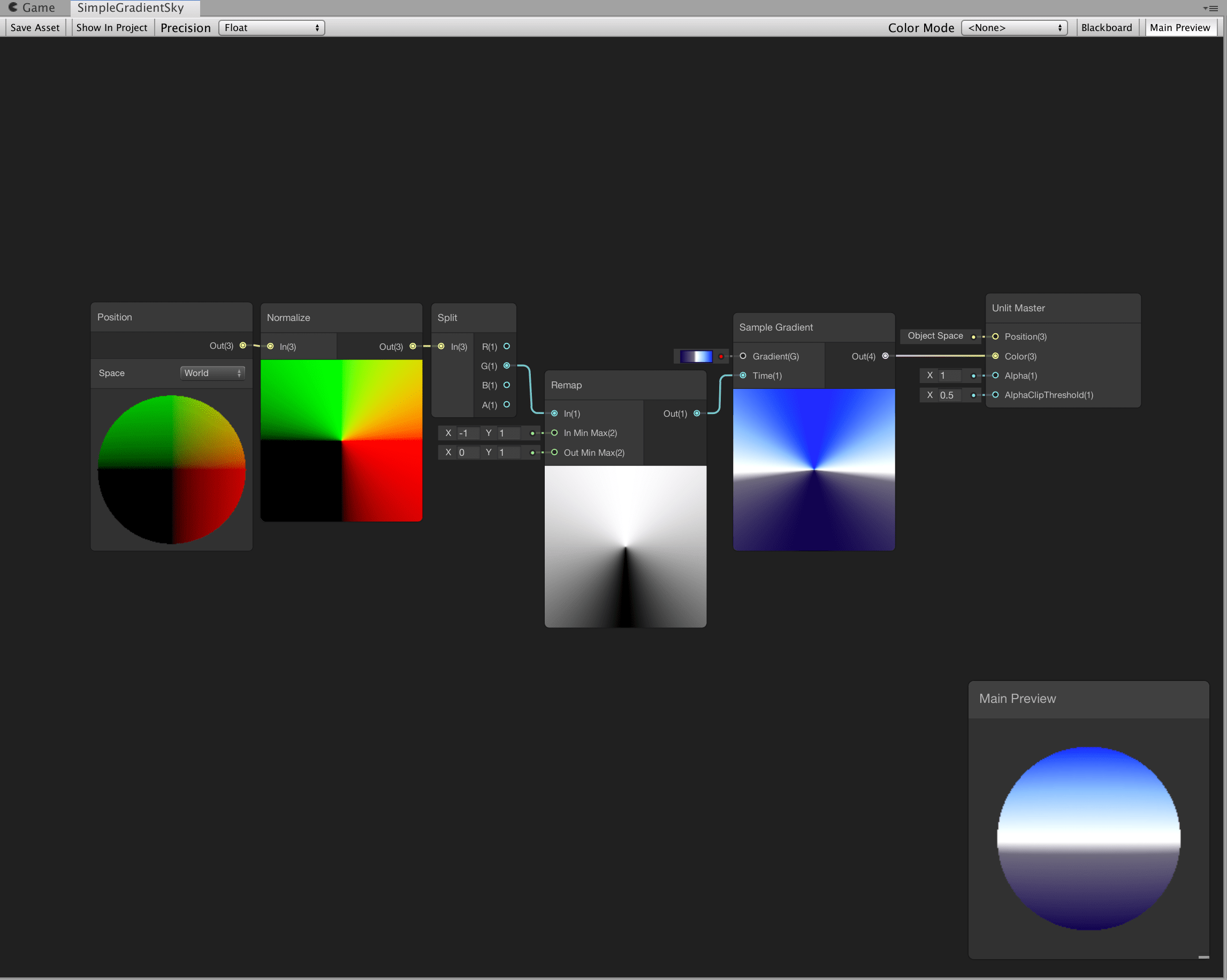
so far all four blend modes display this screwy blending when near eachother

I need a sollution that allows them to be adjacent without this occuring
i have a shader for a FullScreenPassRendererFeature. the core of it is
float4 _BlitTexture_TexelSize;
half4 frag (Varyings input) : SV_Target {
    UNITY_SETUP_STEREO_EYE_INDEX_POST_VERTEX(input);
    half4 tex  =  SAMPLE_TEXTURE2D_X(_BlitTexture, sampler_BlitTexture, input.texcoord);
    return tex;    }
but its outputs grey? I can see in the frame debugger that the actual _BlitTexture shows the actual scene
full shader is here, nothing too special - https://pastebin.com/fU95q8Qc
I didn't solve my problem, a series of extremely ugly hacks that are barely half working, extremely inferior useless sollution, but this at least shows what im trying to achieve

How do I do the above, except not hideously ugly?
The 'real' sollution is to somehow give the shader a 'minimum' or 'maximum' blend mode
https://docs.unity3d.com/Manual/SL-Blend.html
how do I do these in shadergraph?
Do I have to compile and show code and somehow edit that?
hi i made this simple shader for texturing my terrain (im new to shaders) and applied it on the terrain is it still possible to draw textures on the terrain for creating paths etc. or how would you do that?


not jagged but not precise either
still working on it
xy im still trying to solve the above, how can I in shader precisely control a gradient of values into a very specific curve?

I know 'power' changes the curve, but Im struggling to visualize what the resulting gradient currentlky looks like
I got the values to be tight enough I guess, end sollution was judicial use of power, multiply, and extremely faint gradients


Did you try debugging with the frame debugger and/or PIX? Or RenderDoc might help too.
Something that lets you look at the buffer contents. Not sure off top of my head what ones of those will let you dump the buffer, since you're after the 1st element (red, opaque).
I can't verify your code fragment, and I don't know where you set the variable "shaderMaterial". Makes sure "length" isn't zero too. Perhaps you want sharedMaterial not Material in the reference from the renderer if that's how you set it.
hi guys, not sure where to go with this - Unity game screen is pitch black only when a plane (with shadergraph) is visible from the camera's POV. Do you know why this might happen? It seems to work as intended in Scene view
that looks very nice :D
is that metaballs?
either a texture is missing or lighting
could be a shader outputting blank
thank you, is there anywhere I could see an error that's not in console?
not sure if you can see errors for that kind of stuff
also maybe something is not transparent or is transparent
thanks I'll retrace my steps
How do I do an extra pass that just adds a masked texture on top of a previous Surface Shader pass?
aren't there meant to be two outputs for this??

i am extremely confused with this branch node
Pseudocode

"Use Pass: DrawEyeWhites"

surf ()  {

  texture irisTexture;
  texture opacityTexture;

  irisTexture.alpha = opacityTexture.a;

  o.Albedo = irisTexture;

}
How do I get something like this working?