#archived-shaders
1 messages · Page 39 of 1
I am pretty sure your sprites are transparent, so make sure to connect the alpha node from your texture to the alpha of the fragment
Hello, I'm repeating the function by loop (120fps) below to make a rendertexture slowly fade (multi is between 0 and 1). When the slightly transparent rendertexture A is processed through material _Post with shader PostPen and then blitted onto B, it seems that B has some sort of black background or something, hard to explain. The video shows some colored strips, but they gain brightness=0 properties where alpha is considerably higher than 0.

as the Fade() function's "multi" decreases from 1, the blackness which can be seen in the strips approaches 0

probably since the strip's alpha reaches 0 in like a few repeats when multi=0.9
the video demonstrates multi=0.99
Hello there, not sure If I have to post this here, I want to enable the SRP batcher / GPU instancing for my project as I have many objects with the exact same mesh and material but it is just not working, I even followed the steps provided by unity for using it but no result. I'm using HDRP and I realized that enabling GPU instancing flag on the shader does not work because of the SRP batcher. does anybody know how to fix this
how do you know that gpu instancing isn't working
He probably checked with frame debugger
"probably"
There's some info here about intentionally breaking the SRP-batcher compatibility for certain objects without needing to disable it entirely. https://docs.unity3d.com/Manual/SRPBatcher.html#intentionally-removing-compatibility
In short, use MaterialPropertyBlocks on renderer, or in shader declare a property not inside the PerMaterialBuffer. For graphs, I think you can do this with the "Override Property Declaration" setting on an property (e.g. set an exposed property to "global")
You got any reference as your goal?
Like COD Modern Warfare. Nothing complex, just a standard white line around the object.
I dont know the games visuals. but did you google for outline tutorials on shadergraph? There are a trillion about it. Just pick the most recent
Most of them is outlining all edges. I alredy managed to do this kind of shader.
I want something like the Unity Editor has. It outlines gameObject in oragnge if you click on it.
Still enough tutorials. You want something like a wall see through outline or RTS like selection. Just get the write keywords in google 😉
Outlines in general are quite complex. But the simplest is the "inverted hull" method that redraws the mesh pushing out normals.
e.g. If using URP, can use this shader/material with the RenderObjects feature : https://github.com/Unity-Technologies/UniversalRenderingExamples/blob/master/Assets/_CompletedDemos/ToonOutlinePostprocessCompleted/Shaders/ToonBasicOutline.shader
Also got a bunch of links about outlines here https://www.cyanilux.com/resources/?filter=outline
Thank you, its a good resource. I'll try out some solutions and come back with more exact questions if I have.
Does anyone know how to only call #pragma multi_compile _MAIN_LIGHT_SHADOWS_CASCADE when shadow cascades is enabled (>1) in the URP asset?
Currently my shader (graph) breaks when shadow cascades is at 1, while this pragma is there
It would already be doing that. The multi_compile pragma complies the shader into two versions/variants, with and without that keyword (and code it relies on).
Actually in v11+ the correct way to handle the shadow keywords is actually as an enum, like #pragma multi_compile _ _MAIN_LIGHT_SHADOWS _MAIN_LIGHT_SHADOWS_CASCADE _MAIN_LIGHT_SHADOWS_SCREEN, to avoid creating unnecessary variants.
If by "breaks" you're referring to an invalid "shadowCoord" error, then you can fix it by using #undef REQUIRES_VERTEX_SHADOW_COORD_INTERPOLATOR in a custom function.
I know it should, it works in 2020 and recently fixed it in 2021, but not 2022 gives issues.
It also gives the issue if I use the enum (but without shadow screen, since that breaks 1 material)
By breaks I mean the shadows just stop rendering without error :/
Hi, I am really close to my desired effect with shaders, the glow part of my sword can be seen as transparent over the UI in low lighting, anybody know how to fix this?


as you can see, middle image is middle lighting level and the effect becomes a problem
this issue also occurs with floor tiles, but it is less noticeable as floor tiles are lighting dependent, whereas the UI is permanently 'lit'
With a little more thought: I think I'm looking to clear all alpha values underneath my glow material

problem solved
Anyone got any idea why this is? lol
So... Standard URP shader has Tiling settings.
Any idea what is name of that property? To set/get from material in runtime?

It's likely the Tiling & Offset values associated with the _BaseMap texture, so would be float4 _BaseMap_ST; in the shader.
As that's marked as the main texture, I would assume material.mainTextureOffset and material.mainTextureScale should allow you to set it.
_BaseMap_ST as float4, huh
I am doing entity material override, so no material helpers for me here
any idea which part of float4 though? 😅
xy components is scale/tiling, zw is translation/offset
I see, thanks
hmm, doesn't seem to be working
I need direct reference of shader property
same as _BumpScale for example
It's no help in entities
Not sure what to suggest, that is the correct reference
https://github.com/Unity-Technologies/Graphics/blob/master/Packages/com.unity.render-pipelines.universal/Shaders/LitInput.hlsl
since there is no Material exposed
And using the IComponentData method with _BaseMap_ST doesn't work ?
https://docs.unity3d.com/Packages/com.unity.rendering.hybrid@0.51/manual/material-overrides-code.html
no
looking into MaterialOverrideAsset atm
but doesn't seem like it has it either


annoying
but I guess I can solve it with my own shader
Any tip how to implement tiling? 😅
turned out to be a node actually
Thanks for the info! it seems the reason why the batcher is not working is because of Entities graphics (my project uses ECS), whenever I disable SRP batcher or use override properties I get errors in the console related to BatchRendererGroup which is part of entites graphics
Hello, I have an issue regarding Graphics.Blit, where if I blit a RenderTexture A onto a RenderTexture B through a material called Post, and the post-processing shader in Post makes A have some transparency, then B turns out different; instead of B having transparency as well, it inherits some black color. It seems like Graphics.Blit is putting A onto some black image and making that be B. I was wondering if I could avoid this in any way. Thank you very much for your time.
It's a little unclear what you're asking, but afaik Graphics.Blit does not deal with transparency. You shouldn't use transparent blend modes, just sample the source texture as _MainTex and alter it.
https://forum.unity.com/threads/blend-mode-on-transparent-background-texture-used-for-compositing.542683/
Is the above link related to this matter? Their issue seems related, how do I work with blend modes?

Unity Forum
Hello,
I'm working on an AR game that needs bloom for the 3d objects without affecting the camera feed image. To do so, I'm rendering the content on...
basically this is what happens, and the latter demonstrates the use of Graphics.Blit
the shader itself is pretty simple, just changes the alpha of the source texture. There might be a simple workaround that I'm not considering

I need to recreate this shader in URP. I've got the Shader Graph Shader Editor window open, but can't find the equivalent properties from the left. Where are they!

how can i get the color wich an object is standing on ?
Some are accessible in the graph settings tab of the graph inspector
Some simple don't exist
Best you can do (in shadergraph) is to use the scene color node (transparent objects only) to get the color of what is on the screen.
Else, you will need to find other ways to do what you want like raycasting with script
oh, so I'm gonna have to write it instead? 😬
What propery in particular do you need ?
could i make a custom node for this ?
Stencil buffer. Need to recreate this shader in URP

Stencil in URP is used with renderer features
so i feel dumb but i cant connect some of my graph to the vertex(position) node in shadergraph. are there limitations here or is this a bug?
For raycasting ? Physics.Raycast is a c# function, so not for shader.
You could maybe hack some things around, but seems very complicated
There are limitations, in particular texture sampling : for vertex stage, you need to use the SampleTextureLOD node
Reformulating the need : what do you need ? A single color for the whole object ? What if the thing which your object is standing on has a texture ? Which color should you pick ? What about the lighting ? : If the object is on something, it blocks the light, so under it everything is dark
i found a difrent way but how do i mage a custom shader compatible with the texture painting o terrain
the object doesent cast shadows, its its grass
A bit old, but still relevant : https://forum.unity.com/threads/terrain-custom-shader-graph.1172447/#post-7510127
Assign the material with your shader to the terrain, and assing the terrain splatmap and textures to the material
Oh, so you need to get the terrain color, for grass blending with the ground I guess
Tricky, but I think you can use a script to get the terrain basemap and use this as a rough terrain color
yes
hello i did atmosphere shader URP and it is not showing both side. i checked render face both, but not working. can you help me?
A shader I am using for trees to try and make them "wave" still has issues. 1. there seems to be a pause, they wave a little, return to the original "position" i guess, and then rest for a moment before moving again? and i dont know why. 2. there are artifacts of little white dots whenever it waves. The shader is being applied to Tilemaps, I will send a picture of the shader along with a video of what its currently doing

Hey, i might be mistaken, but i think there was some kind of preview window for materials (shown as on a sphere), but no such preview pops up anymore.
Im on URP and unity 2021.3
is there a way to get a material preview?
Make sure you have main preview selected

I downloaded a water asset but i dont know how to apply it can anyone help

If you're referring to the material inspector, it's likely just minimised. Should be able to drag the bar at the bottom to expand the preview
Create a new Material, select the shader (Shader Graphs/Water Volume-URP) on the dropdown. Assign that material to the plane.
Since the shader is intended for URP, make sure you're using that render pipeline or it'll appear magenta.
how do i use render pipeline?
Be aware that other shaders intended for the Built-in pipeline might not work if you switch to URP
hey im wondering what block "divide" give as result from two arrays and how it works?

Huh? There's no arrays here. But if you mean the Vector2s, it's returning a Vector2 doing division on each component separately.
you cant divide two vectors
I'm sorry! but i don't understand I am new to unity

Lol that was it. never would have guess to just drag on random border 👍 thanks
You can in HLSL. Math operations on vectors does them per-component. float2(a, b) / float2(c, d) would be equivalent to float2(a / c, b / d)
https://learn.microsoft.com/en-us/windows/win32/direct3dhlsl/dx-graphics-hlsl-per-component-math
The shader assigned to that material is still the Standard one. You can change the shader on that dropdown.
Though it'll likely appear as magenta error material, as the water one you downloaded is intended for URP not the Built-in pipeline.

what should i change it to? and i think i have URP also thanks for your help
I hear they make creating post processing easier for shader graph but only for unit 2023,any plan to make this doable for older unity version?
I have a shader, where I multiply the cross of the object position, with another vector, to then use it as an axis for rotation (plant wind)
but it has a problem
when the position is the origin, 0, 0, 0
the cross product is 0
what can I do in that case?
I dont know how to solve this without using an "if"

If URP shader appears magenta but standard shader doesn't, as in the previous picture, that suggests you didn't configure URP as per the instructions
he has rendering but i don't


I can see it in both, just not in the same spot
Omg I'm so sorry
for the shadergraph, i changed it from Sine Time to normal Time, but it didnt seem to change anything
now this one is pink?

That's expected
Built-in RP shaders aren't compatible with URP
how do i fix it?
You don't
You choose a render pipeline and only use shaders that are compatible with that
Instead of Standard shader you'd use URP's Lit shader
how do shape keys/blend shapes work? like, how is the info passed from the cpu to the gpu
because it seems to be able to, have different materials, so its not a material property, and it isnt per vertex, so its not a vertex attribute
or skinned meshes
same deal, info being passed per mesh
I need a way to pass info per mesh, and I would rather not have to create a new material for each mesh
also, the moment I set a property in a material, the updates to the sharedMaterial stop affecting the material, even if it isnt the property I updated
Any idea what's happening with my Shadergraph normals?
(Above: the ShaderGraph; Below: The shader applied to a sphere)

It's likely post processing (i.e. tonemapping) affecting it
Yep, looks like that was it: The Neutral tonemap looks bad on negative numbers.
shadergraph make me commit war crime mmmm, fun i am not having, commit a war crime, i will
i cant find anything on what could be causing the "pause"
I'm getting the following harmless error message quite frequently
Metal: Error creating pipeline state (Hidden/Universal Render Pipeline/CopyDepth): depthAttachmentPixelFormat is not valid and shader writes to depth
(null)
anyone know how to get rid of this? I'm using URP 14
Hi guys, I found a shader for a Holosight that involves stencil buffers but the shader was not for HDRP, can someone be kind enough to help me convert both shaders 😦
In urp, how can I compile a shader for fog_exp2 only?
Hello I am having problems with my terrain shader graph.
When I make a float in shadergraph, It automatically makes the float work on the X axis. I want to make a float that is on the Y axis
how do i do that
Make a Vector node and connect the float to the y component
vector 3 node?
If you need XYZ then yes
hello
it did not work

do you want the shader to check it?
please help
i am a newbie sorry
it all went pink
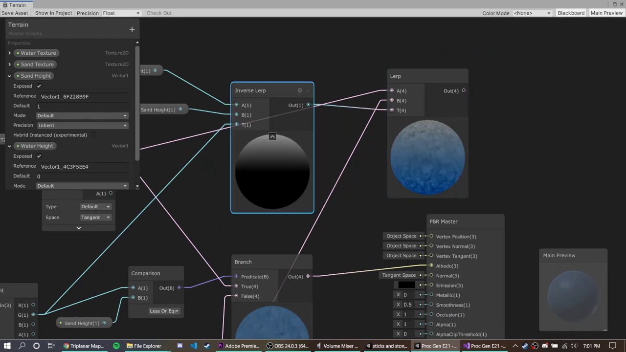
this is a terrain shader for procedural map generation, and when you apply the shader the terrain looks like this:

i want it to apply on y axis, instead it is applying on the x axis
sand hieght is 03
0.3
this is the tutorial i followed :
https://youtu.be/uJSxqr3a0cA
DOWNLOAD THE PROJECT HERE: https://github.com/jacklaplante/Unity-URP-Terrain-Shader
FOLLOW ME ON TWITTER: https://twitter.com/_snubber
This tutorial explains how to use the new shader editor graph to create a shader for procedurally generated terrain that works in the new Universal Render Pipeline in Unity.
Then some other input value you are giving it is zero or otherwise invalid
Hey guys Im having and issue with a StencilMask shader for my Holosight
Basically I want the crosshair to be visible only while looking through the glass of the holo
But for some reason I cant figure out how to make it render behind the skybox while not seen through the glass
Here is a video showcasing my problem:
does the shader graph not support tessellation in version 2020
well no
what is the best way to make water. I cant find any tutorial that goes in to details and how to set everything up
Refraction, transparency, possibly use the depth texture for foam and blending
Normal maps, scrolling textures
Theres some keywords for you
Semi-vague question but I've made a relatively large function in a compute shader and call it in 3-4 places in the shader. This has however made the shader take like 30 seconds to bake every time I edit it. Any idea what might be causing this? Is it because I have a lot of return points in the method, or maybe just because it contains a for loop?
how do i make the noise move?

Move the UVs
with?
its just blinking

I'd use Time node into a Vector2 node (to select which axis it should scroll on), into offset of Tiling And Offset.
There should also be tutorials that you can find that include stuff like this.
thanks
this as well. but i think a better alternative if you want control would be a parameter into the shader that controls the speed of both axes
Yeah that would work too
is there any way i can make it look more like a wave
ok now my question, is it possible to write my own post processing effects using shader graph without using a blit render feature in URP? or am i pretty much doomed if i want to have a brighter camera
you might want to look up tutorials of water shaders
but maybe someone here knows
also alternatively can i have a specific volume effect only one camera? maybe i could use exposure
If you just want it brighter you should be able to use the post processing volume stuff URP already provides.
There's a volume mask on the camera
maybe. but my character has a flashlight, and it would probably look very overexposed if i used exposure during nighttime to make it look bright
You could adjust the exposure amount from a C# script at runtime, depending if it's day/night
I have been trying to find a tutorial but everyone just shows the final result and dosent go in to detail about anything
Use a normal map
yeah but again the difference between pitch black and the character's flashlight is very strong
Can't you use a spot light?
so if i want the minimap to look bright, i have to also make the flashlight look EXTREMELY bright and overexposed
but then that ruins night time
i have not figured out how to render a light on only one camera at least
Light layers?
witch?

thats for affecting objects, not cameras
from height is my guess
From height is kinda pixelated IIRC but you can try it
Best to use an actual normal map
how do i do that?
Download one or create it in photoshop or gimp or some browser tool for example
Try the Normal from height/texture nodes first 🤔
With a basic noise texture like the one in your screenshot
How does a light affect a camera if not via objects though (Except volumetric fog)? Or am I missing some context here
i want light to affect my terrain on one camera
but not the other
In HDRP you can render a light on certain cameras only, I think its similiar on URP
HOW tho, everything ive found says you cant
maybe i just havent looked enough? ive been trying to solve this problem for a while
like this

theres a unity tutorial on youtube for that
no thats not how you use a normal lol
you pass simple noise directly into that blue node
and you also pass it into the normalf from height
you put the light on a maskthats not rendered by the cameras culling mask
then you pass normal from height into the normal output of your shader
that does not work
already tried it
does for me on URP
what am i doing wrong then what
ah right, the light has a culling mask too
not sure which one does what, i just set them both to the layer they should render/illuminate
oh I mean first time ever opening a graph. and Witch blue node I don't understand
the one you tried attaching your normal to
disconnect normal
connect the same way you had before
and then connect normal to your normal map output on the right hand side of your shader
You know, I might have misspoken, looks like I was just using layers on the game objects
But its really hard to test because light layers dont get updated when I change the values, its pretty buggy for me
Couldve sworn that was a feature 🤔
You could probably work around it by changing the terrain's layer just before the camera renders
like this

Connect the noise to the normal from height
In urp these sketchy changing stuff before render things dont work for me
how do I change the color then
If you dont know what a normal map is/does, you are expected to look it up
Or ask. Its just to fake some surface detail without adding extra geometry
I wanted to make the sound look more like waves and someone said i should use normal from height
Yeah
The normal map should be connected to the "normal" output of your shader
NOT base color
Omg thanks I'm so sorry
Apologies for my naivety but why is this happening?

Whats wrong
I'm expecting the triangle to be added to the hollow circle
My understanding is extremely limited
how do i apply a shader to a object
Is there some negative values @tame swan
actually, i indend to subtract the triangle fromt he hollow circle
Use the shader on a material
How would I work that out?
@tame swan You can easilly fix out of 0-1 range value with saturate node
(before the add/mult)
BTW, for shapes intersection, instead of subtract, use min / max nodes 🙂

Nice
Ah thats why you use min max
But if you used the minimum node with the circle and the balck triangle, it would do the same shape at the end, while staying in the 0-1 range
It's the basic operation for signed distance shapes combination : min for intersection, max for union
combine with negate or one minus (depends if you workd with real sdf, or black/white shapes), you can do :
min( 1-A, B) -> subtract shape A from B
Oo fun question i have
How do I map a texture onto a white spot in a shader graph
So does the preview just show absolute values?
I have a sun/moon shader, and i would like to map a texture onto my moon, so i need to know how
The preview, as it displays colors, is limited to values in the [0;1] range in RGB channels
I think anything over 1 is 1 and everything under 0 is 0
Yeah
Ahhh I see
Lerp
Lerp
A = base
B = new value
T = mask
Output is A if T = 0, B if T=1, and a mix between A & B in between
So, take whatever your base is for A, the texture for B, and the white moon mask for T
That's up to you on how you want to map the texture
The moon moves through the sky so if the moon moves the texture would change since its just a mask
Yep
Ahhhh alright then
Ill try and figure it out i guess
At some point, why not do this with objects instead of trying to do everything in a single shader ?
Not sure what you mean


yeah
Have something like a plane for the background/sky, and a quad for the moon on top of it, instead of using a single shader to drawn everything
Did you SAVE the shadergraph ?
thanks man
extremly dirty hack im using (for now at least):
attach a sphere to your world direction light with 5km offset and scale it up.
voila, its a sun
Games are holding up with hacks like this 🙂

I guess i can have a fancy shader for the sun and make it have emission or something and give it glow if i seperate, i think i will try this
But how do i make my moon/sun fade behind clouds? Do i need physically based clouds? Is there a good guide for this
if its on a skybox, everything is rendered in front of it
or make the cloud shader render after the sun shader so it overlays
unity keeps putting these weird spots on my build once I generate the lightmap and bake the lights, anyone has a idea how this could be? I'm really lost at this point.

Can you switch your scene view mode to Texel Validity?
something tells me that the "red" isn't exactly good lmao

so, uhh, to fix that 😅
is that a issue with the 3D model of the "building" itself or a lighting issue
https://forum.unity.com/threads/lightmapping-troubleshooting-guide.1340936/#post-8467202 It's a problem with your models exposing backfaces
Unity Forum
Introduction
I developed this guide in order to help developers get the most out of Baked Global Illumination (GI) in the Unity Editor. Here, I unpack...
Yeah my dad needs to look into this 💀
(he makes the 3D model, I do the lighting.)
What the hell

all I did was add three light sources
good news! I fixed it!
bad news! I have no clue how 💀
I suppose that there are enough valid rays from the lights you added to the middle that reach the texels that were invalid before 🤷♂️
Still kinda sus
It seems to be that way yea haha
Thank you, for your help. I appreciate the quick response !
how do i make it more transparent

How?
Step 1 make sure your surface type is set to transparent, step 2 set your alpha value
? Wdym
I thought the sun is supposed to be its own object
does time counted for how long the scene "played" (eg: the trigger was activated in 50 second of game, unity count from there (50, 51, and so on))
or when it triggered? (eg: I trigger the animation at 50 second unity count 1 from there (so in 51 second it's 1 second, 52 it's 2, and so on)

How long the scene played
let's say it's 50 second when triggered
I was no asking, but answering 🙂
ah yeah my bad
The time value is the time in seconds elapsed since the scene started (It might even be since you've entered play mode)
is there's any way to reset it to 0?
Not that I know of.
But from script you can get Time.time that is the same value, pass it to you material through a property, and do a subtract to "offset" it.
Or you could just use a custom time variable updated from script
so basically the time node in shader mostly used for something continuously repeating rather than in given time frame right?
Yep
https://youtu.be/1yevpCAA_rU on 7:35 how do I get those purple ball texture
Bring your game to life with this stunning crystal clear stylized water Shader Graph.
Download project files (Patrons only): https://www.patreon.com/BinaryLunar
This tutorial will cover creating the following features for your water Shader Graph:
1- Depth fade with deep and shallow colors.
2- Refraction
3- Foam
4- Waves
5- Smoothness
In additio...
Those are just SampleTexture2D nodes, with an assigned normal map
But previewed in 3D and not 2D
How do I do that
Grab a normal map texture representing waves, add a Texture property in the blackboard, drag the property in the graph, and connect it to a sample node
If you are asking questions like that while trying to follow a water tutorial, I recommend that you start with a more beginner friendly tutorial , probably searching for "introduction to shadergraph"
Where do I get a map texture? It’s really just the water I need to set up in shaders
Google ?
Does it matter witch one I take
Obviously, changing the texture will change the look of your material
For scrolling/offset-time noise shaders... Whats a good way to avoid seams like these?
tilling the texture so that it repeats itself
Is that simply done with just a tiling and offset node within shader graph?
i guess and making sure that the textue itself is seamless
hmm ty
I still cannot figure this out
What is a non-naïve way of handling character blinking, ala Smash Bros, or any game where player takes hits, or has invincibility frames?
Is this best handled at the shader level with a property?
dang, this is weird, I need it to behave more like an unlit shader during the blinking
Could achieve that by just swapping the renderer's material back and forth
But if you use a single shader, maybe slight emission could help in making it look "unlit"?
Might be easiest... this is not terrible for performance? Just checking
I wouldnt say its terrible. Having a single more complex shader would have its own performance costs too, though probably neglible.
I wouldnt worry about it
👍 Thanks, I'll go that route
Though it's probably too early to be worrying about optimization on that level, there's render pipeline differences for that sort of stuff
SRP batching for example shrugs off extra materials if they're similar

I'm on HDRP, for whatever that's worth. Maybe I will try pursuing using material property blocks instead, seems like it might be easier actually, but no idea of that's gonna wreck my instancing or anything. Kind of a shader noob
HDRP does use SRP batching which is not compatible with MPBs or instancing, and usually outperforms both
Your recommendation in this case might be separate materials representing the different flicker states? It's tricky because I'm copying Smash Bros, which appears to quickly ease between the flicker state and back to normal over the course of several frames.
(but I can't be entirely sure... so hard to analyze crappy compressed YouTube frames, haha)
I think the way to do it is to use a script to loop through all mesh renderers and their materials, store those in an array in order, replace them with the bright material when flicker on, and when flicker off loop again and replace them with the previous materials from the array
Or use a shader that can lerp the base color and/or emission color to white based on a property controlled via scripts
Both of them seem valid approaches
Thank you, sounds good.
I'm in a somewhat performance critical situation since I'll be trying to support 4 player splitscreen (cameras), so little performance optimizations along the way could help because a mistake could be 4 times as expensive as a single player game
(in HDRP... good luck to me...)
HDRP is kind of the worst fit for that due to the overhead cost of the cameras, as I'm sure you've noticed
There's the Frame Settings which could be helpful to cut down noncritical rendering features
Yup, many many features have been significantly degraded/axed
Still, I get decent performance. ~60-70 FPS currently 4 player splitscreen 5120x1440 on a 2070 Super
can't ask for much better from HDRP at this time...
A URP shader I am using for trees to try and make them "wave" still has issues. 1. there seems to be a pause, they wave a little, return to the original "position" i guess, and then rest for a moment before moving again? and i dont know why. 2. there are artifacts of little white dots whenever it waves. The shader is being applied to Tilemaps, I will send a picture of the shadergraph. along with a video of what its currently doing.

Ok so the "white dots" from the second problem is because the shader is being applied to each tile individually (I think), and when one tile moves beyond its 1x1 limit it wraps around to the other side (I think) (major thinkage) (still don't know how to fix that).
I cranked up the values of the material to make the issues more clear and visible (white dots inbetween tiles) (waving seems to stop when the values for WindSpeed get high enough i think)
How do I make it so that the snow (white stuff) is on the top of the mountain, Followed by rocks, grass, sand and water respectivly

here is the shader if anyone wants (tutorial) https://youtu.be/uJSxqr3a0cA
DOWNLOAD THE PROJECT HERE: https://github.com/jacklaplante/Unity-URP-Terrain-Shader
FOLLOW ME ON TWITTER: https://twitter.com/_snubber
This tutorial explains how to use the new shader editor graph to create a shader for procedurally generated terrain that works in the new Universal Render Pipeline in Unity.
I think it is because of the water height, sand height etc floats, but these floats are values for x axis, i dont know how to make the floats that represent values for Y axis
cant i make one myslef?
If you know how to, yes you can
okay thanks
do you know nay tutorial
Nothing on top of my head
do you know any tutorial that explains what it is?
what will happend if i skip this part
What part ?
sampleTexture2d
Well ... you won't have normal maps, and the surface won't profit from detailed lighting
Handy browser tool for generating normal maps from images
https://cpetry.github.io/NormalMap-Online/
Online NormalMap Generator FREE! Create a Normalmap directly inside your browser! No Uploads required, completely client-based
If you dont have photoshop or anything
in what file form should i download it to
it dosent look the same as in the video https://www.youtube.com/watch?v=1yevpCAA_rU&t=455s
Bring your game to life with this stunning crystal clear stylized water Shader Graph.
Download project files (Patrons only): https://www.patreon.com/BinaryLunar
This tutorial will cover creating the following features for your water Shader Graph:
1- Depth fade with deep and shallow colors.
2- Refraction
3- Foam
4- Waves
5- Smoothness
In additio...
7:35
Note that you need to import the texture as "normal map" and not "default texture" in the texture import settings
Hi! I finally managed to get that shader for the water, but I have a little problem... As you can see, in the scene view, the water looks perfect with that foam on it, but once I switch to the game view, the foam isn't on the water at all (the one at the edges)... Any idea what's going on here?


why does is look like that

Wrong "Type" setting in the sample nodes.
Carefully look at what was done in the video you've shared
Looks like the depth effects aren't working. Is the Depth Texture enabled? If it's URP, would be on the URP Asset.
Yep, depth texture wasn't enabled, thanks
The Position node (absolute world space) -> Split -> G is the Y axis. You should be able to remap that (using Inverse Lerp like that video does, I'd Saturate too to make sure values stay between 0 and 1), and blend/lerp between textures using that as a mask.
how to make planet atmosphere?
thank you, But what do you mean by "G"
im a newbie sorry ;;-;
The port on the split node, they are labelled RGBA which corresponds with XYZW.
oh okay
it's called Substance from adobe, i never use it tho
okay thanks
Hey, I'm trying to translate a parallelizable algorithm to HLSL as a compute shader. In the original code, I was using rather big constant lookup tables, which often were in the shape of nested arrays.
As far as I understand, cbuffers are good for constants. However, matrices and vectors don't support some of the sizes of the lookup tables, for example an array of 8 vector3 fields.
Is it stupid to just split up the matrices into smaller ones (for example matrixA holding the first 4 and matrixB holding the second 4 fields, and then in code conditionally selecting the matrix if the index is for matrixA or B)?
Or is it a legitimate thing to do?
does gimp work well for this application? thats what ive been using.
I use gimp too but I dont think it has normal map generation built in
there is an option under filter>generic for normal maps
Oh nice
well i was asking if it works well lol
dunno if anyone else knows
it seems fine to me but im not a normal map expert
It seems good enough for most purposes
@distant dirge Seems like you have to use Flip Y so it's in the correct format for Unity
The difference is not too noticeable for some patterns
i mean my test is snow soooo
Yeah that might look good with Flip Y off too

How can i get rid of shaders?
Elaborate (you dont)
Disabling all scene cameras could do the trick 
You can define your lookup tables as static arrays in HLSL
I'd prefer that over constant buffers.
Is there any reference how to make a shader compatible with SpriteRenderer?
property names and etc
for URP
in particular interested for Tiling and Offset
Ooh, how come? I‘m very new to shaders (but advanced with normal OO languages), so don‘t be afraid to be more detailed :)))
I passed an array of integers from Unity C# into an HLSL shader's StructuredBuffer, but all of a sudden that array's contents seem to be persisting between Play sessions. No matter how much I randomize that array of int, the running game proves that the same sequence of integers is still being passed into the shader

Basically, no matter how many times I restart Play, the same pattern of Beige and Orange (pulling in data from the array of integers) happen. I've confirmed that the RNG is working properly, but passing in new sequences of integers still doesn't change the StructuredBuffer
What methods exist to supply random data to a single shader/material? Specifically not based on it's world position.
Example of what I mean: 100 of the same shader/material on objects, each object doing sine time different from a different 'moment' so they dont all pulse identically
the reason not based on world position is because the thing has to also move, and it will flicker wildly if it moves and its based on world pos

visual example of what I mean
is there a way to supply random data so that all of those can have random colors, but not based on world pos
Is there a function to just ask for a specific pixel instead of having to convert into UV and use a texture sampler?
I want to store a whole bunch of non-color data in a fake texture, but extracting them back in a custom node is awkward.
I dont think unity provides any data of that type to you, you have to provide that data yourself (like give the material the objects id)
Ah wouldnt passing that data into the material make a separate instance of the material? Is that performant?
Yes, or using material property blocks. No, making bunch of material instances is not great for performamce
There may be some way but none that I know of. I think buffers are the way to store and access data at certain position, textures are mostly meant to texture objects
you can also use gpu instancing
If the objects use the same mesh and otherwise same material, sure
is there a way to color a sprite in the UI based on the color behind it?
for things like a aiming reticle to make it negative or compliment the color of what ever is behind it
Hey! Anyone able to give me a hand? Trying to create a shader that limits colours to a palette and pixelises the texture but it seems to just make the material brown
       fixed4 frag (v2f i) : SV_Target
          {
                half dx = _PixelWidth * (1. / _ScreenWidth);
                half dy = _PixelHeight * (1. / _ScreenHeight);
                half2 coord = half2(dx*floor(i.uv.x / dx), dy * floor(i.uv.y / dy));

            float4 baseCol = tex2D(_MainTex, coord);
            float4 palCol = tex2D(_PalTex, 0);
            float palDiff = 1000;

            for (int p = 0; p < 37; p++) {
                float baseColDiff = abs(tex2D(_PalTex, p).r - baseCol.r) + abs(tex2D(_PalTex, p).g - baseCol.g) + abs(tex2D(_PalTex, p).b - baseCol.b);
                palDiff = min(palDiff, baseColDiff);
                palCol = (abs(palDiff - baseColDiff) < 0.001) ? tex2D(_PalTex, p) : palCol;
            }


                // sample the texture
                float4 col = tex2D(_MainTex, palCol);
                // apply fog
                UNITY_APPLY_FOG(i.fogCoord, col);
                return col;
        }
        ENDCG
    }

Ignore the colour 1,2,3,4 I gotta remove that lol
try color distance instead of difference
So sorry I'm really new at this what exactly would I be swapping out? I thought difference here was all self-made variables
gimme a second
Really appreciate it thank you!!
fixed3 baseCol = tex2D (_MainTex, coord).rgb;

fixed4 col = fixed4 (0,0,0,0);
fixed dist = 10000000.0; // for prosperety

for (int i = 0; i < _ColorCount; i++) {
    fixed4 c = tex2D(_PalTex, 0);
    fixed d = distance(baseCol, c);

    if (d < dist) {
        dist = d;
        col = c;
    }
}
UNITY_APPLY_FOG(i.fogCoord, col);
return col;
try this
Should I be declaring original somewhere?
sorry got it confused, should be baseCol
Sweet!!
So sorry to keep bothering you!! Just wondering why this error is now popping up?
This is everything I've got
   v2f vert (appdata v)
            {
                v2f o;
                o.vertex = UnityObjectToClipPos(v.vertex);
                o.uv = TRANSFORM_TEX(v.uv, _MainTex);
                UNITY_TRANSFER_FOG(o,o.vertex);
                return o;
            }

           fixed4 frag (v2f i) : SV_Target
          {
                half dx = _PixelWidth * (1. / _ScreenWidth);
                half dy = _PixelHeight * (1. / _ScreenHeight);
                half2 coord = half2(dx*floor(i.uv.x / dx), dy * floor(i.uv.y / dy));

                fixed3 baseCol = tex2D (_MainTex, coord).rgb;

                fixed4 col = fixed4 (0,0,0,0);
                fixed dist = 10000000.0; // for prosperety

                for (int i = 0; i < _ColorCount; i++) {
                    fixed4 c = tex2D(_PalTex, 0);
                    fixed d = distance(baseCol, c);

                    if (d < dist) {
                        dist = d;
                        col = c;
                    }
                  UNITY_APPLY_FOG(i.fogCoord, col);
                  return col;
}

        }
        ENDCG
you're not returning correctly
Oops my bad
return after finishing the for loop
Is it not already returning then?
   v2f vert (appdata v)
            {
                v2f o;
                o.vertex = UnityObjectToClipPos(v.vertex);
                o.uv = TRANSFORM_TEX(v.uv, _MainTex);
                UNITY_TRANSFER_FOG(o,o.vertex);
                return o;
            }

           fixed4 frag (v2f i) : SV_Target
          {
                half dx = _PixelWidth * (1. / _ScreenWidth);
                half dy = _PixelHeight * (1. / _ScreenHeight);
                half2 coord = half2(dx*floor(i.uv.x / dx), dy * floor(i.uv.y / dy));

                fixed3 baseCol = tex2D (_MainTex, coord).rgb;

                fixed4 col = fixed4 (0,0,0,0);
                fixed dist = 10000000.0; // for prosperety

                for (int i = 0; i < _ColorCount; i++) {
                    fixed4 c = tex2D(_PalTex, 0);
                    fixed d = distance(baseCol, c);

                    if (d < dist) {
                        dist = d;
                        col = c;
                    }
                  }
UNITY_APPLY_FOG(i.fogCoord, col);
                  return col;


        }
ENDCG```Perfect!! Thank you so much!!
does it work?
It's taking the colours from the palette now but seemingly only applies 1 colour no matter how high I set the colour count


you're using _ColorCount right?
it should be an int
Ah I see my bad my bad
that shouldn't matter tho
Same error even with int unfortunately
Setting it to 0 affects it though so it definitely is doing something
Now that i think of it it may be worth me reversing the order of operations so it remaps the colours THEN pixelises it
Appreciate all your help anyway!
ey, hopefully quick shadow question this time, I have the following stencil shader but it seems to either catch or cast shadows as you can see in this screenshot. How could I avoid this? It shouldn't render at all unless it's in the card art "window" but itseems to happen with some effects and shadows where you can see a transparent thing in the shape of the sprite that should be hidden.
https://hastebin.com/share/iqiyeduceh.csharp
As you can see the shader code is rather simple too, thanks!

Hastebin is a free web-based pastebin service for storing and sharing text and code snippets with anyone. Get started now.
i found this shader for toon water and for some reason whenever i remove depth of field from my post processing the entire material just becomes white.https://cdn.discordapp.com/attachments/497872424281440267/1089431397485269062/ToonWater.shader
Hello, any one did a cartoon-like metal stripe shaders before?
https://www.youtube.com/watch?v=6iDN7ynzals
Basically I use the tangent vector to use as UV for the stripe, at some angle it's very beautiful (see video), but for some angle it does not appear at all.
I think it is something with the fact that the tangent vector is 3d, while UV is 2d.
How do we got consistent showing of stripe?


I made Bor's new hammer and test in game.
⭐️Support my works
https://www.patreon.com/spikebor
https://www.ko-fi.com/spikebor
♦♦♦♦♦ My links ♦♦♦♦♦
Website https://www.spikebor.com
⭐️Follow me
Twitter and IG @iamspikebor
📗 Read my series Happy Meow Cafe on webtoons
https://www.webtoons.com/en/challenge/happy-meow-cafe/list?title_no=387086
or We...
especially the angle at the end of video, there is no stripe shown at all
around 0:03-0:05 of video, it's most beautiful
Is there a way to get the triangle's ID in ShaderGraph?
From what I see HLSL language has "SV_PrimitiveID" for that, but ShaderGraph doesn't recognize it in my custom node.
does anyone find they need to boost the metallic on non-metallic materials to get realistic reflections?
i have a hardwood PBR floor material from gametextures.com
and its very shiny but the metalness in the metalness map is black and it barely produces any reflections. IRL my hardwood floors are reflective af.
@onyx cargo Hardwood and material like that need a shader with "coat"-style reflection.
what does that mean?
It's a shader property in URP/HDRP, not sure how exactly to code it in Legacy.
It's made specifically to simulate coating reflections like varnished wood, car paint and the likes - as cranking up Metallic&Smoothness doesn't really give the proper effect.
I'm following a guide to recreate a stencil shader to render some objects only through a quad, so far seems pretty simple but I noticed that my opaque object for some reasong has details of thinks behind it

Here's the tutorial: https://www.youtube.com/watch?v=EzM8LGzMjmc

Games like Antichamber feature impossible geometry where multiple objects seemingly inhabit the same physical space, but only appear when viewed from certain angles. We can recreate the effect in Unity using stencil shaders and Universal Render Pipeline's special Renderer Features functionality!
👇 Download the project on GitHub: htt...
Sir, we are not a search engine. But here you go https://www.youtube.com/watch?v=DxfEbulyFcY&t=139s

The planets in my solar system project are looking a bit hostile and uninviting, so in this video I'll be attempting to add some cozy atmospheres around them.
Watch the previous solar system video: here: https://youtu.be/lctXaT9pxA0
Some notes:
• I made a little build where you can play with the atmosphere settings yourself, which you can find...
Looks like SSAO. The stencilled objects (cyan cube) probably aren't rendered into the camera depth and normals textures since you've excluded them from the default opaque layer mask. You may need to handle that manually via a custom renderer feature.
Possibly something like this
https://gist.github.com/Cyanilux/be5a796cf6ddb20f20a586b94be93f2b
Bit outdated though, might need to switch to using RTHandle stuff for 2022+
Probably also want to use DepthNormals shader tag ID and no override material
Afaik it's not possible. Might be able to bake that data and pass it through Vertex Color? Though not ideal, since that means duplicate vertices
Oh I see, the SSAO is another "stack" that gets added to the base render, so the stencil gets exclude from that calculation right?
I have no idea of what RTHandle is, if there is a newer/better way of achieving that result please feel free to let me know what it is
@regal stag It look like Amplify Shader Editor has it actually. Will try to rebuild my prototype with them and see if it work.
Kinda? I don't think it's the stencil that's causing it though. It's just because those objects are taken out of the regular opaque rendering queue/layermask.
This is the current render setting

The base opaque layer mask renders everything except "layer 1" which is the only thing that the override renders
Exactly, so that layer 1 likely isn't rendered into the camera depth and normals textures, so the SSAO feature doesn't know about them
I found out that a simple solution seems to just set ambient occlusion in UPR Renderer Settings to After Opaque
still have to find it tho
oh it was just a toggle in the SSAO render, seems it fixed it well
Now last thing to consider is if and how much this render thing has impact on performances
i know this video this method is good but it has bad perfomance
Define bad performance and tbh. anything that requires taking samples is going to be more performance intensive
If taking samples is not so much your thing, then you can fake some atmosphere scattering with some hacks that look about right
i did shader but its working only front
cool
it is visible from space but from earth it is not visible (
and what do you want me to do about that
i dont know :d can you help me?
possibly yes
how?
What about elaborating what you have done, sending the main part of your code and what do you want to change
here or pm?
if you do it here, other people might also be able to help
create sphere from sphere. create material from this shadergraph and assign it sphere
I cannot open this right now, send it in a form of a screenshot

what exactly should I do with this
i want to be visible on both sides
I am aware of that, but you did not send me a screenshot of your code, you sent me a screenshot of your shadergraf file which is completelly useless to me

You could try changing Render Face from Front to Both
If you want the fresnel to work on back faces, you'll also need to flip the normal vector. Something like this

i tried both but not working
If I where to make an atmosphere shader, I would do it using a post prossesing shader
im trying to make some visual effects to use on this 2d mesh im procedurally generating, i made a mockup in photoshop of roughly what i want to get it looking like, any idea how to do something like this?


from the googling i did it seems like doing outlines like this on 2d meshes is impossible for a shader to do? is there something else i would need to use for that
bless you god :d
pretty sure he's a human
One way would be, change the edge of the mesh to be something like this. You can then set vertex colour or uv data on the outer/inner edges to get a 0->1 gradient, which you can recolour in the shader.

not really sure what that means can you elaborate, i just started learning shaders
Well this is more changing the mesh generation. There's not much on the shader side.
yeah what is the vertex color i mean how do i edit that
If it's procedurally generated, you'd set it through the Mesh class. Either using Mesh.colors or Mesh.SetColors() function. https://docs.unity3d.com/ScriptReference/Mesh.SetColors.html
It would store a colour value per-vertex, which gets interpolated in the shader
alright thanks ill give that a try
editing the mesh like that might be tricky, its generated by sampling along a grid so making them scale out like that would have to go off the grid
ill see how it looks just using the mesh i have now first
as for the transparency in the middle im sure thats a lot simpler but when i tried to make it the transparency was only either fully opaque or invisible is there a setting i need to enable to get partial transparency
I'm sorry if this is a stupid question, how do I set up a public variable in HLSL?
fresnel effect has opposite effect
I tried doing js Shader "Assets/PlayerVision" { _MainTex ("Texture", 2D) = "white" {} but got the error, "Shader error in '': Parse error: syntax error, unexpected TVAL_ID at line 3"
using vertex color with the unmodified mesh, progress at least!

You need to put it inside a Properties {} block
https://docs.unity3d.com/Manual/SL-Properties.html
Thank you
cyan can help?
i want like this

now it is

i want transparent fade out color
Hey, I'm sampling a cubemap and rotating it in a shader, but there's a weird effect that happens:
It seems to have these random blue and reddish squares on it, but when I put it onto a cube or a sphere the issue isn't there


Here is my graph:

I'm trying to set this as the skybox material, and it appears fine but the reflections have a weird blue tint as a result of (I'm assuming) the big blue squares
Oh actually nvm, it does't appear properly, it appears like this:

ok I think i've fixed it by setting the material type to transparent
how do i pick a mesh to use in the preview here

clicking it just gives me this error

That is how
The error is not intended behaviour
which shader node do I use to mirror a texture?
You could also set the sampler state to mirror the texture, or the import settings on the texture to mirror. UV values outside of 0-1 will mirror.
There's a text version of an explaination here:
https://docs.unity3d.com/Manual/SL-SamplerStates.html
    Wrap modes can be specified per-axis (UVW), e.g. “ClampU_RepeatV”.```
As far as SG and nodes, there's a sampler-state node that should help you.
https://docs.unity3d.com/Packages/com.unity.shadergraph@16.0/manual/Sampler-State-Node.html
Thanks, I will try.
I had a question but after spending 30 minutes to write it correctly, I found the solution, so thanks you 
hi, so i know we can make a heat distortion effect using scene color node in shadergraph, but let's say instead of distort it i want to make it more clearer, how do i achieved it?
you mean sharpen the image?
yeah.that one

In this post-processing shader video for Unreal and Unity, I show how to create a filter that blurs the image by taking 7 samples and blending them together. Then I show how to use that same filter to apply sharpening to the final image. Next week, we'll use everything we've learned so far to create an underwater appearance.
Here's last week's...
I guess this could work for you🤷
thanks man

@stiff furnace
Probably a mix of (1 or 2) fresnels with different intensity, and (smooth)step
can help me?

i did but it is not visible both side
Hmm never used the blackbody node.
I'd try with 1 regular fresnel and a one minus fresnel and then maybe use (smooth)step on it
not possible, you can assign multiple materials to a mesh tho, one unlit and the other not
OK, HOW DO I MAKE IT TO WHERE PARTS OF THE MATERIAL ARE ON PARTS OF THE MESH
oops caps
sorry
what? What are you saying? Where parts on the mesh are on parts of the mesh?

oh I read mesh instead of material, sorry
all good
you can go into blender for example and assign the material only on parts of the mesh
but if you tell me what you want to create I might be able to give you a better solution which only needs one material
so i want the buildings to be the exact same but
the neon colors glow
thats it
am i able to mask it with an emission?
yes, you can do it with emission and a bloom post prossesing shader
In this case it has nothing to do with the shader being unlit or not
I made a script that only is able to place objects on a plane if it is at least 20cm away from the edge. Now I want to show this area in the mesh renderer. I am using the standard PlaneMat from the template. I want to show the area where the user can place objects in green and the rest in red. Anyone managed to do something like this?
if it's just a simple plane, you can use uv coordinates to check and render the green part i guess
i tried but not working can you help me?

Something like this?
And then tweak the values
it is visible both side but it is not good result
What?
If you want something be very specific
We dont see what you see
@stiff furnace

@tight phoenix sorry for the ping, but I got curious, I see you hacking away at something cool each day here, do you happen to have a collection of these effects somewhere, where people can check these out? or are they for private projects? 😄
Back to the stencil shader I was working few days ago, the last thing I need to fix is the fact that the camera renders object outside the stencil layer, as you can see the sphere on the botton should be cut once it gets inside the render plane, how I should exclude objects from different layers from being rendered above??

Unity again break skyboxes.. Previously I could just simply make Shader named Skybox Shader and material named Skybox Material and it was working but now? This happens, any possible ideas what is going on?

Standard Unlit shader works fine.
This is the result I'm trying to achieve


Yo, its mostly just a disorganized mess on my end. I am learning shaders and trying to do them for small projects but atm there is no single full repo
Basically this but I want to not render objects outside the layer I select, think it as some sort of window on another dimension
In this example I've already done the stencil part but from the plane with the selected render layer I want to exclude the inner cube

So you need set of N cameras and each need render your desired dimension.
So for each dimension you need camera.
That render this dimension on render texture.
And then you need map result on face with correct aspect.
Yeah that was plan b but the the render texture will be flat
It does not matter.
what do you mean?

so it will distort based on camera position?
But there is some limitations.
Render texture need to have same aspect ratio as your "game".
yeh for sure the render texture is one of them, I don't want to have 1 camera for each of these windows
Ah, I was hoping for a showcase more than a repo 😄 The dice set was especially cool a few months back. It's allright tho 😄 good luck with the shaders! 😉
I will have more to show in the future 👍
Ill try to put together a showcase if the stars align
I don't really know if this is a shader question, but is there a way to set the value of the depth buffer over the entire screen?
draw a full-screen quad 🤔
GPU question - technically for Unity but I don't think it's engine-specific:
Do textures get loaded in-GPU as float3, float4, or is it flexible and follow whatever format it had CPU-side?
Asking because I'm using textures to transmit non-texture data to my shader.
Most of it is float3, and I want to know if it can optimize it by setting the texture as 24bits format, or if the alpha channel is going to be there anyway and I should use it to cram more data.
Ok thanks, I'll do that.
I have a kawase blur when my UI is open but it doesnt always work with other shaders (water and glass shader here) at a certain distance and i dont know why


Just getting started with writing shaders, and I'm getting the pink error material on my sphere, where I'm expecting to see some lighting and an actual color applied. I've rewritten my code maybe a million times but I have no idea why this is happening. Here is my code: https://pastebin.com/XjQTLUaR


Pastebin
Pastebin.com is the number one paste tool since 2002. Pastebin is a website where you can store text online for a set period of time.
what does this mean: cs use PGM to create an input mesh for ocean wave modeling. Here, PGM is a good choice as the moving ocean surface hides the morphing vertices its in the context of oceans waves on spheres
What is PGM?
Also second question (lol), I am trying to make some gerstner waves on a sphere, so I wanted to ask if I managed to successfully convert this math talk into code? ```cs
//WorldSpacePos is in my case the position of the sphere gameObject
float3 o = normalize(v.vertex - WorldSpacePos);
float3 vec = normalize(v.vertex);
float3 dir = cross(vec, cross((vec - o), vec));
        float r = _Radius;
        float li = acos(dot(vec, o)) * r;

        v.vertex.xyz = vec * r + vec * (_Amplitude * sin(_Frequency * li + _WaveSpeed * _Time.y)) + (_WaveSteepness * _Amplitude * cos(_Frequency * li + _WaveSpeed * _Time.y) * dir);


Hello, I have a gameobject using shader "Universal Render Pipeline/Lit". Could you please tell me how to set it "transparent" at runtime using C# script ?
Currently I try this:
GameObject go = GameObject.FindGameObjectWithTag("MyTag");
Material m = flagStick.GetComponent<Renderer>().material;
m.SetFloat("_Surface", 1.0f);
m.color = new Color(m.color.r, m.color.g, m.color.b, 0.3f);
I can see in the editor that the Surface and Color values are correctly changed, but in game the gameobject is always opaque.
don't think you can change the render type at runtime through a c# script
Hi, I try to achieve a rat ondulation
But it looks like that, can you figure out what I miss to join all the vertex?

Can you send your shader?
@hot kelp I found my error, thanks 🙂
Procedurally generated material?
hi, sorry for asking. may i know is there any method to replace alpha in the sprite to white color by using shader graph?
do you mean show white when there's alpha transparency, or actually replacing the color in the sprite with white when there's alpha transparency?
both answer is yes btw
replace the alpha transparency with white color
basically add a white background to the current texture that has transparency
then this should be done by code, not shader
just read the pixels from the texture using GetPixels, interpolate between pixel colors and white by pixel alpha, then write the modified pixels into the texture using SetPixels
or a proper image editor
nope it's persistent grid mapping algorithm, just haven't read carefully enough
Desperately need help on seeing why I'm getting errors here
          struct appdata {
                float4 vertex : POSITION;
                float2 texcoord : TEXCOORD0;

            };

        struct v2f
        {
            float2 uv : TEXCOORD0;
            UNITY_FOG_COORDS(1)
                float4 outvertex : SV_POSITION;
        };

            sampler2D _MainTex;
            sampler2D _PalTex;

            sampler2D _Palette;
            float4 _MainTex_ST;


            uniform int _ColorCount;
            uniform fixed4 _Colors[256];

            half _PixelWidth;
            half _PixelHeight;
            half _ScreenWidth;
            half _ScreenHeight;

            v2f vert(appdata v)
            {
                v2f o;
                o.vertex = UnityObjectToClipPos(v.vertex);
                o.uv = TRANSFORM_TEX(v.uv, _MainTex);
                UNITY_TRANSFER_FOG(o, o.vertex);
                return o;
            }

            fixed4 frag(v2f i) : SV_Target
            {
                  half dx = _PixelWidth * (1. / _ScreenWidth);
                  half dy = _PixelHeight * (1. / _ScreenHeight);
                  half2 coord = half2(dx * floor(i.uv.x / dx), dy * floor(i.uv.y / dy));

                  fixed3 baseCol = tex2D(_MainTex, coord).rgb;

                  fixed4 col = fixed4(0,0,0,0);
                  fixed dist = 10000000.0; // for prosperety

                  for (int i = 0; i < _ColorCount; i++) {
                      fixed4 c = tex2D(_PalTex, 0);
                      fixed d = distance(baseCol, c);

                      if (d < dist) {
                          dist = d;
                          col = c;
                      }
                    }
  UNITY_APPLY_FOG(i.fogCoord, col);
                    return col;


            }
                ENDCG
    }
}
}```"Shader error in 'Unlit/GB-Unlit': invalid subscript 'vertex' at line 66 (on d3d11)"
try renaming outvertex to vertex
or o.vertex to o.outvertex
With compute, try both and see what works best. It also depends on how you send and receive the data in both c# and shader.
Unity probably stripes the alpha channel data if it's not there, but not 100% sure
Is there a way to make a 2D shader consider only a single sprite and not the take the entire spritesheet with it ?
I'm talking about these types of spritesheets :

The spritesheet is the base texture the 2D shader will work with.
The sprite is sort of a "where to cut" information.
You can pass this info to the shader with c# code, it's basically a tile/offset value
Thanks I'll look into it
Hello everyone, I have a little problem: I have a Sphere and I want to have something which is working like an outline shader. I am working in AR, and when I am looking at a sphere I want to see the circle, which is like the outline of the sphere from the current position I am standing at. This is kinda working right now with fresnel effect (+step & lerp), but when I am streaming the video of the view to another device, the circle is filled black and not transparent so I don’t see the content which is behind the black filling of the circle – the content which should be circled... I have already adjusted a few settings (surface type, transparency-value), but I was not able to get the result I am looking for. I would be glad if anyone could help.

Does anyone have a link to a good outline package on asset store? Or is there a pre existing unity solution to produce an outline?
I'd like a blurred outline on 3d objects
Is it possible to get a normal map that is stored as a secondary texture with 3D lights? I only see it mentioned with 2D lights

Ive setup my secondary texture as suggested but I dont seem to get any effect
Thats only for 2d lights
Is this still on a SpriteRenderer? I'm not sure secondary textures get used otherwise.
Also what shader is being used? If it's something like Standard / Lit, the normal map property name is usually _BumpMap
If you need partial alpha/transparency, the Surface Mode needs to be Transparent.
If you just want to discard some pixels, can keep it Opaque but enable Alpha Clipping in graph settings.
For either, you'd then connect the fresnel/step to the Alpha port that appears in the Fragment stack.
@regal stag This is what im currently using on my tilemap renderer

Your v2f struct uses outvertex, but you're trying to do o.vertex in the vert function.
I'd try naming the secondary texture _BumpMap then, as that's what the URP/SimpleLit shader uses.
You may also need to assign a texture to the material to make sure the _NORMALMAP keywords are enabled.
@regal stag Sadly no dice:

That's the base map, try assigning one here?

My hope is that'll keep the keyword enabled so it uses the correct shader variant, and the Tilemap renderer will override the texture to the secondary one. But just guessing here.
This has an effect but not quite intended:

It doesnt seem to map to the correct tiles
No idea then, sorry
Ah no problem thanks for trying. This is what I get for trying to use 2d tools inside of 3d 🙂
@regal stag I may have actually figured it out
I think you are right its just the other tiles in my sets dont already have a normal map setup so its applying the default

Also I know my normal map is borked just testing
Oh right, I see there's a dark blueish colour on some of the squares in the first normal map.
The path tile and the grass are separate sprite sheets so now I have a normal map for each it seems to work
Thanks for the nudge in the right direction regardless ❤️
yes you can, @lyric vortex set the blend mode to read from a property then set the property through your code
hey im a unity beginner (i hope this is the right channel) and currently trying to create a tree now i want to create the leaves using as less triangles as possible but if i do it like that (image) you can see the single planes is there a way to avoid this effect? (heard sth. about depth / z- buffers)

use one of the set methods in a material instance to control properties at runtime

from something i wrote
maybe do the leaves as a basic sphere with a transparent texture? could play around with zwrite too, see if that gives you a result you like


Does any one know if there is a urp shader for TMP or Super Text Mesh, that is lit? I am using STM right now and it seems to only have unlit shaders.
Ive made a simple shader to make a texture visible in 3D space by applying the material to a quad. Now is it possible to give the said quad some depth thickness based of what is not alpha on the texture?
Anyone able to help me work out how to fix this
Pastebin
Pastebin.com is the number one paste tool since 2002. Pastebin is a website where you can store text online for a set period of time.

So you have height map stored on the alpha channel and you want to make the quad look like it has 3d bumbs in it?
Since in using a plane with 0 thickness I want to know if its possible to give it volume by shader
What do you mean by volume? It could mean a couple of things
Maybe just vertex displacement based on the texture alpha?
hi guys, how do we use GPU instancing on shader that created with shadergraph? I'm on unity 2021.3 and trying to make a custom 2D shader that will replace pixel color
Something like this? The quad is the red square and I want it to have that blue depth

You may be able to fake some depth with parallax effects (e.g. offsetting with tangent space view direction), but you won't be able to render outside the original quad.
Might help, https://www.cyanilux.com/faq/#sg-gpu-instancing
Hello ! Just wanted to know if it was possible to use a smoothness texture (or an entire material) in a VFX shader graph ? The only things I see about that are these float 🤔

If you're using a VFX shader graph inside VFX Graph, it should list whatever properties you set up in the shader graph Blackboard here
So do you mean something like these fake interior shaders or do you want to cut holes in the plane using the alpha in a way it looks like it is thicker plane?

Yep, but in VFX graph is there a way have a texture input and not a float. As I can use a texture (from my black board)
i would create a second texture that stores a distance map; outlines are complicated and usually expensive
thanks!
Hello, I have a dog model that I want to make it look like a ghost and follow you around. How can I remove this effect that I see here on my object? (marked with red)

The transparency adds up, i can't find anywhere how i can fix this to show only the mesh that you see, without the parts in the background
you need an empty pass to clear those
            Name "Empty"
             ZWrite On
            ColorMask 0
}```I am using ShaderGraph since the project is in URP
oh, I dont think its possible with only shader graph
I dont know if colormask is available to set via shader graph, but you can add a second material with a code shader that just does that pass
make sure the empty pass material is first in the material list though
okay thanks, that worked
works like a charm 😄

awesome 😄
Let me give you a straight example, I made an texture sign that I then apply to a quad to make it visible in a 3D space, I just wanted it to have thickness. But nevermind I'll just do that in 3D as a mesh
Image of that "texture sign" would help a lot
Hi, I'm new to shaders.
Is there a way to have these cubes make parts of the purple mesh fully transparent?
I want to make a fog-of-war type thing

Forgot to mention It's in URP
hey so i want to learn shader graph but every tutorial i am watching shows me the nodes or how to create a specific shader now the question: how do you know which node to use when? (please send me some useful tutorials)
There is no list of rules to say what nodes to use when.
Node are mathematic operations and functions. It's up to you to figure out the goal of your shader, the inputs you have available (UV, texture, properties) and set up the logic to achieve the desired effect
@lime vector could you explain what you want to do again?
Do you mean like the purple ground having transparent 'holes' in it?
someone get this man a texture sdf calculator
Do u have a link for it
no, I tried searching for it haha
you have to generate a texture map where each pixel has a value encoded into, which gives you the nearest distance to a surface
that way you can wrap a gradient all over it to your liking
SDF is your keyword, but I got no idea if any tools exist, sorry.
Can also search for "jump flood algorithm" implementations in unity, as that can be used to generate an SDF afaik.

here it's described, but I was hoping an artist tool would have this implemented by now
it's not that uncommon
If you use noise textures and step at a threshold to generate this kind of 2D terrain/map that might also already work as a distance field kinda. Would multiply by a large value and use a Sine function to get the repeating lines. Then take noise again, remap a section of it and mask those lines.
I know catlikecoding has one, though it might be a bit old and not sure it worked last time I tried it
https://assetstore.unity.com/packages/tools/utilities/sdf-toolkit-free-50191
https://catlikecoding.com/sdf-toolkit/docs/texture-generator/
I would imagine it's hand painted, usually you would want more control. If you layer noise you also kinda lose that distance field-iness the more you layer it
thats pretty nice
would do the job
I`m using navmesh to generate it
navmesh -> mesh
then draw from top with a ortographic camera
Edit oops, I was scrolled up
is there to make a portion of a shader lit and another be unlit?
yes there is, at least in built in
how?
make a texture mask and make a custom lighting function which interpolate between lit and unlit based on mask value
https://docs.unity3d.com/Manual/SL-SurfaceShaderLightingExamples.html
is there a way to do this in shader graph? i havent really started learning how to make proper shaders
that is something I'm not sure
well maybe you can use an unlit shader as a base, and add some manual lighting calculation, then interpolate between them using a texture mask
i think in that case I might just use 2 sprite renderers and have 1 that uses the shader material as that seems more simple. maybe one day ill learn how to actually code shaders
Yeah that's pretty much it, I want to make holes so I can see where the cubes are
I'm looking to recreate the Killer7 Shader with shadergraph, as shown in this video: https://www.youtube.com/watch?v=NmcuJbcEddU

I want to make a cel-shaded game (I had a look at this effect https://www.youtube.com/watch?v=lUmRJRrZfGc) but with that simplistic colour-only style seen in killer7 where everything has a gradient, rather than using textures
i want it to look exactly like in that video, but all the tutorials and code I find online are doing a more BOTW approach to cel shading without the gradient
because it's not cell-shaded (except for the characters), it more looks like screen space gradient
how do I achieve that effect in shader graph?
I want cel shaded characters and screen space gradients for the geometry
ideally also those hard shadows
if anyone can help me create my shader it would be cool to hop in voice chat and do it together if anyone is down for that
idk if anyone on this server does collaborative work like that but hmu if so
Can make the screen space gradient by using the Screen Position node, Split and take the G output (Y axis). I'd put that into an Inverse Lerp to remap it, then Saturate. That gives you where the colours should transition, as in the video I think the gradient itself is only really in the center of the screen - the top third is solid colour at least? (a little hard to tell with the compression)
For applying colours, can put it into T of a Lerp, with A and B set to color nodes/properties. e.g. https://www.cyanilux.com/tutorials/color-swap/#lerp
For the toon/cel-shaded part, if you use URP you should be able to find shader graph tutorials for that, but you'll need custom functions to obtain lighting info. e.g. https://github.com/Cyanilux/URP_ShaderGraphCustomLighting
Should be the Transformation Matrix node, with View on dropdown
thank you! I will try this out asap 👍
I'm trying this now. Wondering about the inverse lerp node and how to get it to show anything (im pretty new to shaders in general)
it seems to work!
I just messed with the value on the lerp
this isn't quite producing the effect i wanted however - it's not "looking" at the camera

meaning the effect breaks when the player looks around
why my material is not shown up in Unity (i used alpha textures)


You are using the screen position input, which means that the effect is based on the pixel position in screen coordinates : the gradient will "stick" to the screen, whatever the position/rotation of the camera. Is this what you want ?
Look at this page to see how Unity (tries to) import materials : https://docs.unity3d.com/2021.3/Documentation/Manual/FBXImporter-Materials.html
Looks like it didn't import properl as transparent, and didn't find the alpha map.
Else, you can still re-create the material yourself in unity
yes, you worded it much better than i did lol
like how old games would do skyboxes, where the texture is the same no matter the orientation of the camera (or the end gateways/portals from minecraft for example)
So, wasn't clear to me, is something not working as expected with your setup ?
sorry, only just seen this. it doesn't quite look the same as killer7 or the recreation. I'll try doing some experimenting with it, and adding outlines and such
I also saw a post about adding persona 5 style "dithering" effects which looks neat so there's always that to try out too
The new dots rendering system need to be provided 4x3 matrices for each mesh Scale/position/rotation.
I know 4x4 have Matrix4x4.TRS to generate them, but I can't find an equivalent for 4x3. And I can't find documentation on this either (even Unity's own sample project just manually fill the matrix but that only work with non-scaled, non-rotated objects).
Anyone know?
trying to convert an existing shader to work in single pass instanced xr environments, but for some reason my object's position (works fine normally and is defined as o.pos = UnityViewToClipPos(UnityObjectToViewPos(v.vertex));) seems to cause bytecode errors from the shader compiler whenever used (ex. o.perspective.x = 1.0f / o.pos.w). The strangest part is that it works fine without accounting for single passed instanced rendering, but while that could be excused as differences in environments or available data, it works when I try and use o.pos.w in calculations in the fragment shader, but when i pass it into a function (ex. myFunc(o.pos.w), it's when I get the bytecode errors. I am legitimately confused.
So I am making a low poly planet and I was wondering if I can just create a sphere that goes into the deep areas of the map that have the water shader. And then I wanna take that and make code that makes the sphere like buoyant or whatever. Is that possible?
Hey folks. I'm pretty new to shaders, but I'd like to find some performant way to make ghibli / botw grass in unity. Any advice? I know a decent bit of code so I'm down to write shaders, but I could use a tutorial or something of the like to start. Using URP. Any advice?
Any advice?
Don't use URP, not yet
I have this shader
It's supposed to make text scroll like this

It works on my windows PC, in editor and build. But it doesn't work on other windows PCs
Please anyone able to help?
if I want to have dot following the normal face of the line, do I need to use normal or tangent vector?

something like this the green triangle is direction following the local face space of mesh

hi, why did my sprite lit shader preview come up different when in game mode


How "doesn't it work" on other pcs ?
That's a very strong statement, and would require some argumentation
The best would be to have the line have proper UVs, U oriented along the line and V perpendicular, and use this to draw the triangles
Probably because they are also facing the light when rendering into the shadowmap
You're doing the billboard effect in the vertex shader by using view vector / direction I guess ?
Instead, calculate the same vector by subtracting the camera position (camera node) to the vertex position (might need to normalize).
That way, it will always face the camera, including during the shadowmap pass
Imagine the shadowmap pass as "render the depth of the scene from the light point of view".
Well, in that case, using view direction/vector gives you values like if the light was the camera
Using the camera node, which contains the camera informations used for a full frame rendering, and calculating those vectors yourself, you force it to be in the camera view space
Got a client's project made in Unity 2021 LTS + URP, asked for optimization, convert to built in, nothing else changed, performance improved from 8 fps to 25 fps on low end android.
is there a way to debug shader variables on the CPU ?
for example how would i log input.worldPos.x
can i write it to some sort of global var and then use mat read vec ?
I think it would be hard to log since shader works in vertex and fragment/pixel
imagine a model with 5000 vertices, with a 512x512 texture, it could dump a lot of log lines
I usually 'log' them by outputting it to the mesh color, where I can inspect it visually

- You need a way to distinguish the outer ring vertices from the rest. This could be by using a vertex color mask for example
- As it's a circle, you "just" have to push them along the radius vector. Normalize the XZ (or whater the plane axes are) coordinates, and add it to the vertex coords
how do I create a vertex color mask?
You can either use a tool in unity to paint the vertex color, like polybrush, or do it in blender
Hey Guys how to create TextMeshPro "fontAssetType=1"
thank you
How to have different compiled shader with only one .shader file?
for some object i haven't normal.
for some object i haven't metallic.
I wont duplicate code
Can define keywords via #pragma shader_feature SOME_KEYWORD, or multi_compile _ SOME_KEYWORD if you need to toggle at runtime.
https://docs.unity3d.com/Manual/shader-keywords.html
You'd then surround the code with an #ifdef SOME_KEYWORD ... #endif
where i set the value of this keywords? like if I have the metallic texture in the shader property I want the shader_feature on
If you want the texture property itself to control the keyword you may need to write a custom ShaderGUI https://docs.unity3d.com/ScriptReference/ShaderGUI.html
Otherwise can have an additional float/bool property using the [Toggle(KEYWORD)] attribute
Might also be able to write your own attribute/drawer that works with MaterialProperty.textureValue https://docs.unity3d.com/ScriptReference/MaterialPropertyDrawer.html
It works like a charm!
hello I'm trying to add this shader to unity but its entirely pink and I don't know what to do. https://www.youtube.com/watch?v=mWg4CE6ybKE&t=112s&ab_channel=SpeedTutor

Ever wanted a FREE water shader for URP and Unity, Including: Reflection, customisation and simple parameters for Unity? Well, here is an in-depth look at the features of the Simple Water Shader for URP & HDRP by IgniteCoders.
➡️Simple Water Shader Asset: https://assetstore.unity.com/packages/2d/textures-materials/water/simple-water-shader-urp-...
was there ever a main light node? iirc you can make a custom node to show it; it's a pretty obvious thing they should add though.
There is a Main Light Direction in 2022.1+
But if you're using URP, I've also got https://github.com/Cyanilux/URP_ShaderGraphCustomLighting
Which has access to light colour, distance atten (which stores if the light appears in the culling mask iirc). Can also sample shadowmap via Main Light Shadows subgraph.
Pink/Magenta means it's not compatible with the current render pipeline. If the water shader is intended for URP, make sure you are using URP.
https://docs.unity3d.com/Packages/com.unity.render-pipelines.universal@12.1/manual/InstallingAndConfiguringURP.html
If it's a Shader Graph you may also be able to change target under the Graph Settings to make it compatible with other pipelines.
ok, I'll try that, thanks 👍
Hi I am having a problem with the lines of the other side of my box showing through the cube, I have this shader graph attached to my cube is this reason why it looks like this?


it also renders through walls

this is what its supposed to look like


https://i.imgur.com/c1ZPmnF.png here is a better image (the link has more resolution)
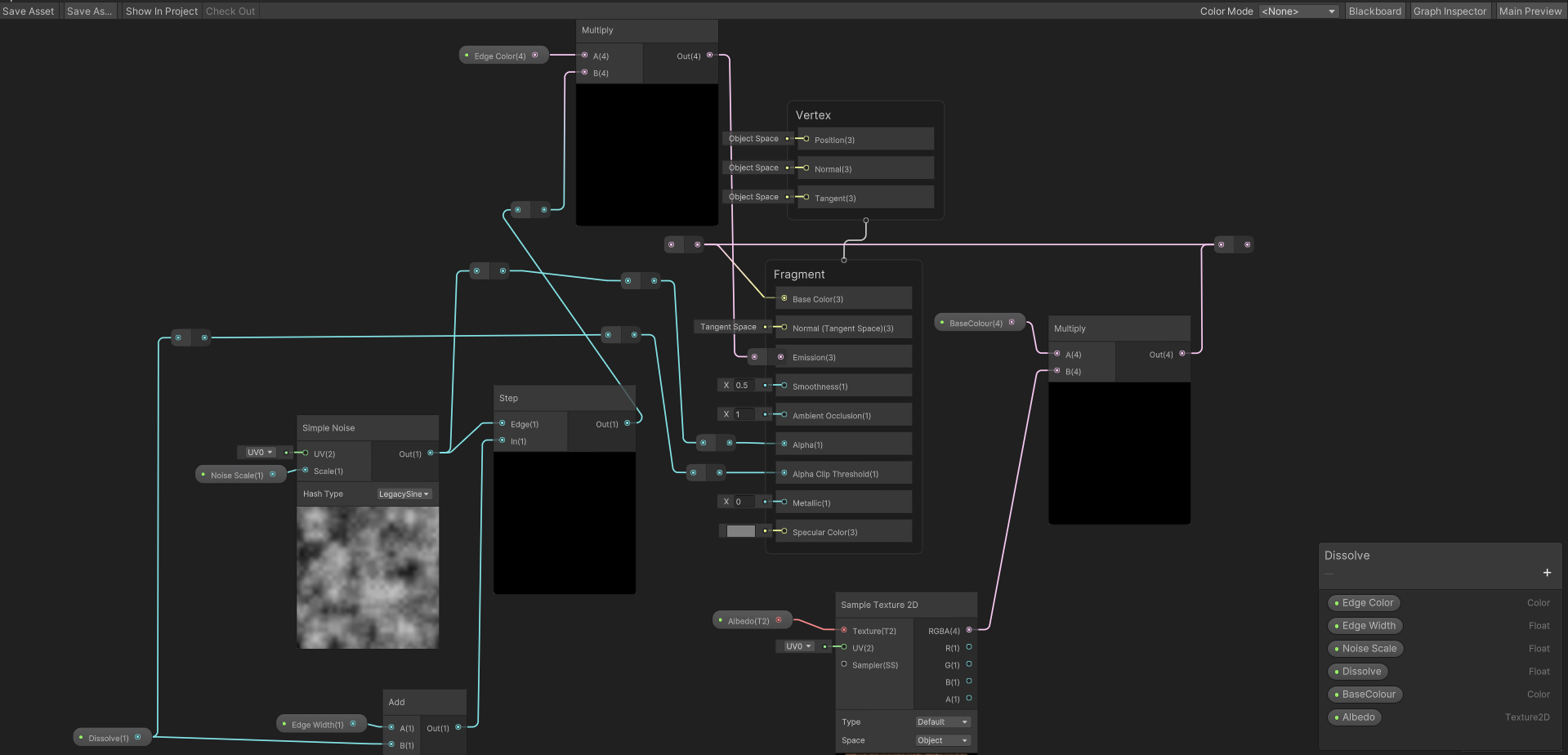
What are the graph settings? Is surface type transparent?
is it a known limitation of material variants that I am unable to lock Vector2 properties on a material?
Hey guys i got this shader on built-in rendering pipeline, its a shader that fades things when the camera colides with them, but with this magnets stickers of the fridge they get not to have transparency info cutout, im trying to make a cutout +fade to transparency, although idk if its possible to have cutout + fade?


Is there a computebuffer that has an extendable size?
No, you must define a max size.
so is there a better option than having an array of ComputeBuffers, and then setting them when you need them, while doubeling the size each time?
I'm having issues with my custom shadergraph, depending on the rotation of the object, the mesh gets colored differently
No clue why this is happening, whether its the fragment or vertex
It's based off a tutorial for a waving grass shader
Without the vertex shader part, which waves the grass, it doesn't change when rotating, but some parts of the mesh are darker then the rest:


Depends on the viewing angle
The most likely reason might be that the meshes are one-sided with the shader rendering both front and backfaces
Despite this only front faces get lighting which is duplicated on the backface, so if the front face is facing away from the light both sides appear dark
If it's not that it could also be just the lit surface reflecting different amounts of light by angle
You could duplicate the faces with flipped normals in a model editor, or use a shader that inverts the normal if it's facing away from the camera
I usually do this
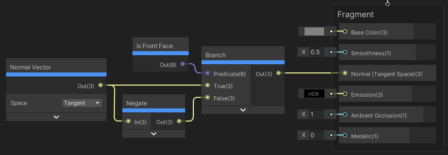

Though there's probably more than one way
Okay, that helped tremendously


But not completely, some angles still have very dark areas
I also use a normal map, instead of that normal vector you use, any difference?
I multiplied the normal map by the normal vector, and the results are great!
The side not facing the light source is pretty dark, but i have no clue how to fix that
If you're using a normal map, you would replace the Normal Vector node in their example with the Sample Texture 2D, rather than multiplying them together
I tried that, and the results were worse
Some faces may still be dark though as they would be facing away from the light source
before, and after


I think a typical way to avoid that is to make the normals match the terrain or point directly upwards instead - which you could do by switching the normal output space to World in Graph Settings and using a Vector3 of (0, 1, 0)
May also be able to keep the normal map, but Transform to World space, add an amount to the Y axis and Normalise to get a similar result.
Yeah, I'm not sure if the normal map is adding much detail here. Can try both and see what works
It looks a bit more fake without it, because it doesn't look lit at all
i'll try both
World space is second image


looks better
im trying to find a good shader graph tutorial and alot of them use the old pbr shader graph and im wondering if there is anything else to use (im new to using shader graphs)
Lit is same as the old pbr
ok thanks
why does the particle system has this black shadow and how do I get rid of it

Your particle texture's color is a gradient from white to black
You'd need a texture that only has that gradient in the alpha channel with a pure white RGB channels, or have the material use additive blending instead of alpha blending
got it,thanks
Hi I am having a problem with the lines of the other side of my box showing through the cube, I have this shader graph (https://i.imgur.com/c1ZPmnF.png) attached to my cube what is the reason why it looks like this?

why does it also render through walls

here are my graph settings too

Hmm, you have Allow Material Override ticked, so maybe the surface type on the material is transparent? (This kind of thing happens with transparent objects as they don't write to the depth buffer. But if you're doing dissolve you can still do that with opaque + alpha clipping)
It really was just as simple as checking one box off 😭
thanks
are there functions that allow you to directly copy from computeBuffer A to computeBuffer B in unity?
Anyone got any ideas why this shader (https://www.youtube.com/watch?v=EzM8LGzMjmc) no longer works on PC?
In Unity 2021.3.16 (probably just 2021.3..?) and URP 12.1.8 the stencil no longer works when the platform is set to Windows/ PC/ Mac. Swap to Android or iOS and it works again.
I used this some months back and it still works on my 2021.3.19 / URP 12.1.10
I haven't used any platforms besides Windows for this project though
Oh, that's good to know - I'll try updating to the latest 2021.3
Nope, still not working in 2021.3.22 / URP 12.1.10 on PC
My implementation seems to be the same as the video so perhaps the issue is with something else in your project
I'd try to do it again in a test project to rule that out and to catch any obvious mistakes
each time I've done it it's been in new projects
Just now though, on 2021.3.22 I had missed something.. sorted it now
It's working on PC
Cheers Spazi
I can't seem to figure out where to mess with shadows, to me, these are to dark, where should I mess with this? The Directional Light settings? Shader Graph?

(Behind the directional light here btw)
So, not sure where to post this, but I'm trying to move creating a texture rendering some mesh using a custom shader from using a custom camera to a pure CommandBuffer approach.
This is in the context of modding, so a limitation is that I don't have access to the shader source, but what the shader does is :
- Outputting the normals in the red channel
- Outputting the depth in the green channel (with inversed values compared to the raw depth)
Example :

The is the result when using CommandBuffer.DrawRenderer(renderer, material) and then calling
camera.AddCommandBuffer(CameraEvent.BeforeForwardOpaque, cameraCommandBuffer);
camera.Render();
However, if I try to do the same thing with a camera, but setting a command buffer view/projection matrices, setting the target with CommandBuffer.SetRenderTarget(someARGB32RenderTexture) and finally Graphics.ExecuteCommandBuffer(myCommandBuffer), normals are going to the red channel as expected, but the green channel (depth) is empty :

Complete code :
CommandBuffer manualCommandBuffer = new CommandBuffer();
manualCommandBuffer.name = "manualDragCubeRender";

Matrix4x4 projectionMatrix = Matrix4x4.Ortho(-cameraSize, cameraSize, -cameraSize, cameraSize, 0f, farClipPlane);
Matrix4x4 viewMatrix = Matrix4x4.TRS(cameraPosition, cameraRotation, Vector3.one);
Matrix4x4 scaleMatrix = Matrix4x4.TRS(Vector3.zero, Quaternion.identity, new Vector3(1, 1, -1));
manualCommandBuffer.SetViewProjectionMatrices(scaleMatrix * viewMatrix.inverse, projectionMatrix);
manualCommandBuffer.SetRenderTarget(manualRenderTexture);
manualCommandBuffer.ClearRenderTarget(true, true, Color.clear);

CommandBuffer cameraCommandBuffer = new CommandBuffer();
cameraCommandBuffer.name = "cameraDragCubeRender";

transform.position = cameraPosition;
transform.rotation = cameraRotation;
camera.orthographicSize = cameraSize;
camera.farClipPlane = farClipPlane; // nearClipPlane is set to zero

foreach (Renderer renderer in part.GetPartRenderers())
{
    Material material = new Material(dgs.dragShader);
    manualCommandBuffer.DrawRenderer(renderer, material);
    cameraCommandBuffer.DrawRenderer(renderer, material);
}

Graphics.ExecuteCommandBuffer(manualCommandBuffer);

camera.AddCommandBuffer(CameraEvent.BeforeForwardOpaque, cameraCommandBuffer);
camera.Render(); // camera.targetTexture is set to a RenderTexture
camera.RemoveAllCommandBuffers();
The RenderTexture are created as follow :
new RenderTexture(textureSize, textureSize, 16, RenderTextureFormat.ARGB32, RenderTextureReadWrite.Default)
{
    antiAliasing = 1,
    filterMode = FilterMode.Point,
    autoGenerateMips = false
};
is there a way to get the world position of additional lights?
I'm trying to fake volumetric lighting and need to do some ray casting
looking through HLSL or CG includes lights don't have that luxury
but, I can get an approximate position using the direction and the square inverse of the distance attenuation
since it is 1/d^2
What's the functional difference between _ScreenParams.xy & _MainTex.xy on image shaders?
Working on an effect using multi-channel shadow maps... I think it's turning out nicely.

ooooo sampling shadows? that sounds sick
using a shader i got from the asset store and it is just not working and really not sure why because i got it working before rather easily... god my brain hurts
you'd tweak your ambient light contribution, possibly GI (if you use it), maybe custom post processing that isn't using ACES tonemapping, maybe overall increased exposure (also via postprocessing). ugly shadows on billboard-style grass cards can be fixed by making a shader that overrides the mesh normals to be perpendicular to the terrain (point up), alternatively you could rotate them in your 3d software.
Thanks for the response, and you reminded me this server exists!
New question!
I can't use the GPU Instancing with the game I'm modding this map in for some reason, the grass refuses to render in game if I use it on the grass for some reason. What could possibly conflict with it? And if I just can't use it, how does the Vertex Lit and Grass mode work? It just renders the mesh vertices in Vertex Lit unless I use URP/Lit.
Before I was using a ton of grass prefabs, but that's laggy as shit, so I'm trying to use the unity terrain system
the reason there was a ton of prefabs is because I was using Vegetation Studio, and the game doesn't support it, because it doesn't allow scripts in maps unless they are DLLs, no clue why.
so it was difficult to get around it, and I baked the grass into the scene as prefabs
that makes it difficult for performance, so I scratched all that, and here I am lol
Any idea why my depth texture seems to be disappearing?
I am using a custom scriptable render pipeline and the PostFX post processing stack. Is there anything unique I need to do to preserve (or create..?) _CameraDepthTexture?

for now, I'm working around it by defining a separate depth target called _CameraDepthMap, but I found that it doesn't work if I do the same but using the ID of _CameraDepthTexture.
Is this the place to talk about compute shaders?
why can't i connect these? they're both real number pins, right?

im really confused about where exactly the nodes are in shader graph to cast to different vectors, wherever they are they aren't named such that i can find them with searching o_o
You should be able to connect the individual rgb components to the ports of the vector3
i seem unable to do this
That is strange to say the least
oh wtf

@mental bone so that specific node was broken i guess? look at the screen closely and you'll see one accepts and the other doesn't
wtf 🥴
Im not sure what is going on but it justworks for me

ok so what's happening i think is that the output types are different in an invisible way
i got the left side connected and the output is not compatible with Normal

so i guess that Normal is not actually a vector and is something else (idk what)
Its a vector for sure
i think i understand the problem
i think the issue is that philosophically it doesn't make sense for a vertex normal to be sampling the texture, i suppose? but i don't know what else to make it.
okay, i'm gonna ask a new question and outline the issue:
hi! so i'm trying to make a retro-reflection shader, and the way to do this is to make the normal of the object always face towards the camera. I'm doing that successfully.
my next goal is to make it so that this black and white reference texture is used to control the amount of reflection. so i'm lerping between the default normal and the modified normal using that texture.
My expected result is that each pixel gets rendered with a normal that's affected by this texture.
i'm not sure how to achieve this in shader graph though. vertex normals only affect vertexes after all but the fragment normals are all in tangent space so don't seem suitable for this purpose either.
Oh I think I know whats the issue. You cant use SampleTexture2D in the vertex stage you have to use SampleTexture2DLOD and provide the lod level yourself
alright, i'll try that. what's the difference between the nodes?
this might seem like a dumb question on the surface but... i don't use LOD management in my project yet.
unless LOD refers to something else
In this case lod refers to the mip level of the texture
Its just how textures are sampled in the vertex stage you have to manually fetch the desired mip level
is it easy to make it use the mip level it was always going to use in that situation anyway?
I dont get the question. You have to manually provide the mip because at the vertex stage the system does not yet know what mip to use
oh, darn.
i was really hoping i could leave mip controlled by the engine. so i have to essentially re-implement mip mapping again in my shader?
i guess i lost mipping when i made a new empty shader
ok wait hold on
You haven’t lost anything
i'm going about this the wrong way