#archived-shaders
1 messages · Page 37 of 1
but you can't access data from one shader in the other
shaders are just their own isolated mini program
you can barely do anything crazy
only way to read and write info in shaders is with buffers
but i'd recommend you just compare the shaders you have by eye and maybe paint
its what everyone does, it's the fastest way
graphics almost never has to be precise
if it looks good, it looks good
maybe if you describe why you need all this debugging crazyness, what kind of effect you want to achieve I can help
Then copy this?
It's not a tutorial or open project so I cant
Not sure what an RP is
No
Render pipeline
The built-in unity one
Well i have clue how to actually write shaders sooo
Shader graph in URP makes life much easier for me
Hopefully someone else knows
No problem and I hope someone does
there's shader graph for built-in now too
you can do outlines by rendering the mesh a second time inside-out, vertices offset by their own normals
and the color is just any color you define
No clue how I'd do that
are smoothness and roughness the same thing?
some threads i just read i'm led to believe if i'm packing a roughness map into the alpha of a metal map for the standard shader, i should invert it first because smoothness is the invert of roughness
Roughness = 1 - Smoothness, is my understanding (aka inverting yes)
@regal stag thanks! I'm using some materials from gametextures.com and I notice if i download their prepackaged version for unity PBR, the metal map has nothing in the alpha (it says RGBA in the inspector, but when i open in photoshop there is literally no alpha channel), and they don't provide the roughness/smoothness map when you choose that download option
that's straight up wrong, correct?
Maybe? I know with Unity the smoothness can either be the alpha channel of the albedo map, or metallic map. That's why there's a "smoothness source" dropdown on the Standard shader. So maybe they put it in the albedo?
I don't work with PBR textures a lot so others might know more
What are possible reasons why object space positions calculate correctly, but the same positions in world space do not 🤔

the only difference between these two is changing from object to world space
The object is rotated or scaled, or simply translated?
Object & world position only match if the transform of the object is (0,0,0)(0,0,0)(1,1,1)
in this picture the world space one is at 0 0 0 with no scale or rotate
which is why the noise is the same shape as the left one, which is in object space
but you can see the normals are completely blown out, despite that being the only difference

also unrelated buy sometimes shadergraph wont let me connect nodes
and I don't know why this is the case
If the chain is connected to the fragment stage it sometimes blocks you from connecting to vertex stage (and vice versa). It's best to keep them completely separate.
There are also nodes which can't be connected to the vertex stage (like DDX, DDY, Sample Texture 2D) but since you're using a Preview node to reroute that's not the issue here.
Are they the same object ? If yes, the left one is definitively rotated then, explaining the difference ?
Ahh I see, yes I had to connected to fragment because I was trying to debug the problem

the left one is in object space
so its rotation is unrelated to the problem
though I dont understand why they dont match in that regard
somehow changing object space to world space did that
I don't know if this is related to the current issue, but for the record btw, if you want to debug the normal, use the Normal Vector node in the fragment stage, as that'll already be the normal you input into the vertex stage.
If you try to connect somewhere along that normal recalculating chain to the fragment stage, it'll be doing the calculations again, with that already adjusted normal, so what you'll see would be kinda wrong.
Sorry, I'm trying to understand what I see and what is the issue, but a lot of things you've said are confusing :
- in the screenshot, what are the color showing ? Positions like you've said ? Looks like normals
- You want to compare object space vs world space positions. Supposely, the world space object in the screenshot (right) is unscaled, unrotated, and placed a 0,0,0
Then why did you rotate the one showing object space ? To have a better comparison, just translate it, it only makes it more difficult to compare if you add rotation
okay, I wasnt doing that because previously connecting normals wasnt working to visualize them
but it seems to be working now
let me try to explain from the top to help make understanding clear
left is in object space, its deformed and recalculated
right is in world space, same, its the same exact shader in every way, except for the space being changed

but in world space the normals are completely wrong
resulting in the blown out look there
It might also be a good idea to make a thread, these conversations always get so long 😅
yeah good point

I need this to be in world space, not object space
but the math to recalculate the deformation normals doesnt work in world space for some reason I dont understand
and I am trying to fix it but I have no comprehension of why its not working
They should.
Switch all the nodes to world (absolute world for positions)
But at the end, you need to transform the outputed normal to object space again.
yeah I was, it wasnt working though. Give me a minute to try to strip out everything to figure out where its going wrong

now its behaving completely differently
when all I did was flip it to object space and back to world space
which makes no @#$@^ing sense
suddenly the normals are correct


but when I move the mesh, it moves further than the mesh moves further than the game object
which also makes no sense
shaders are completely and utterly illogical and random
literally the only thing I did was turn it to object space and back to world space
No they aren't.
Shaders are math, and math are logical and predictible.
that cannot change the shader that fundamentally
k
if you just wanna be a dick to me why do you even bother replying, I need help not abuse
I'm trying to help, and I gave you some guidance, and apparently it worked ? Is that beeing a d**k for you ?
I'm just saying that there is no magic here, and no random value that changes when you look away from you screen, if something doesn't work at some point, and then seems to work after you do "the exact same thing", then you didn't do the same thing.
adding a second material in the mesh renderer achieves the second rendering of the mesh
if you create a shader graph shader and add it to your new material
"Works", but no recommanded nor supported workflow
what is the supported workflow?
Have an other mesh object, or use custom passes (HDRP) / custum renderer features (URP)
and what benefit does it bring to have multiple gameObjects / meshrenderers over multiple materials?
and how much extra work are custom passes?
It is supported.
Let me explain : a mesh/meshrenderer has basically one material per sub mesh. If you add more materials then there are submeshes, effectivement unity will re-render them over, but this is more by chance than something else, and you should rely on this behaviour as it may change per renderer pipeline, or in the future.
Custom passes / rendering feature have the benefit of beeing integrated in the rendering loop, and can automatically re-render meshes from a specific layer with an other material.
I know about the benefits of that part, but try to explain this to a begginer
Here's an official tutorial on how to do it : https://learn.unity.com/tutorial/custom-render-passes-with-urp#

Unity Learn
In this tutorial, you will learn how to use custom render passes to render a toon outline post processing effect on selected objects
Assigning a new material just seems way more convenient
By the way, this is just a random decision that it isn't supported, there's no reason why it couldn't be
The way it would work with multiple submeshes (and I think worked a long time ago), is that after all submeshes are rendered with their material indexes, it would just loop around and all un-rendered materials render with the looped submeshes
with submesh 1 and 2: mat1 mesh1 mat2 mesh2 mat3 mesh1 mat4 mesh2
Well, it is "supported" in the way that we mention it in the doc. But if you have a bit of complex object with more than one material, you're screwed and it won't work anymore : https://docs.unity3d.com/Manual/class-MeshRenderer.html#materials
Note: If there are more materials than there are sub-meshes, Unity renders the last sub-mesh with each of the remaining materials, one on top of the next. If the materials are not fully opaque, you can layer different materials and create interesting visual effects. However, fully opaque materials overwrite previous layers, so any additional opaque materials that Unity applies to the last sub-mesh negatively affect performance and produce no benefit.
I've also read about submeshes and Unity, and it's more like submeshes are not supported not the multi-material part
Submeshes are supported, that's for sure, it's more the behaviour of "more material than submeshes" that is clunky.
Yeah, but again, I wonder why that is since having this would be like 3-5 lines of code added tops
And it would make sense
IDK why it was decided like this, and probably that the persons that took this decision had also valid arguments.
It is now to late to rollback I guess.
Imho, it should just be impossible to assign more materials than submeshes, and that's all.
Imho it should be easier to add custom passes in URP
Until then, i'll just use this when there's 1 submesh
Because what if I don't want to replace the materials? I do not want to replace anything and have any business with tags
just have an object drawn multiple times and to it's own thing
not going to add multiple objects, because that's a useless memory footprint, and if you go back to change something all other objects need to be changed
it just doesn't make sense
Either multiple materials should be supported, or multiple shader SubShaders or Passes that render without any previous setting up
That's the other thing
SubShader
????
what's that even
Why not add support for multiple?
All these old but useful features that have seen no love in URP
It's more about LOD and fallback than stacked rendering. It is supported to have multiple subshaders
ah, so only a fallback
Or LOD, like I said. Raise the LOD shader level -> switch to simpler sub shader
isn't this kindof what fallback also means? in general terms
Maybe I shouldn't have use fallback in that case.
We do have a fallback mechanic for when a shader can not render on a platform/api, it falls back to an other supposed compatible one
Yeah, I know that one, it's also usable for passes, right? Or when passes fail the subshader fails?
According to the doc, it is for the full shader
The command I mean.
But indeed, it states that
If no compatible SubShaders are found, use the named Shader object.
So subshader are used to do fallback within a shader itself
Ah, okay
Thanks! I was able to get it to work

This is the only mention of Property Blocks that I can find with code example. And I needed to enable GPU instancing on the material.
https://forum.unity.com/threads/can-shader-graph-materials-properties-be-edited-locally-in-each-isntance-of-the-material.665803/

Unity Forum
Hello ! I am using shader graph for creating a toon shader. I am creating a library of basic colors that are used for different characters across...
I have a surface shader I cobble together that clips objects to a plane
but I need functionality that the standard shader adds
is there a way to write a shader that extends the standard shader instead of a surface shader, with cginc standardcore includes etc, but have it clip to a plane?
Im still confused about all this never done anything with coding before from what i have seen it should be a pretty simple script just no clue how to make it
Hey, I have a stupid question, is there a way to fixe the normal of a mesh when we apply him a World space texture.
Like :
I have a tilleable texture, I apply it in world space to a mesh, I duplicate the mesh and rotate it on the Y Axis (so the planes faces the same direction).
Actually normals will act like I have rotate the light source.
How to fixe this and make the normal moove only when the light source is mooved ?
Wtf is this?

looks like a light leak
how
I have no idea about shaders, but I'm working on a project with my friend who's not available right now.
He wrote a shader that I have to edit right now.
His shader makes big splotches of paint over objects and I need to make that paint black, but when I set the paint to be black then nothing appears.
I guess that's because black is the alpha channel.


Can someone help me figure this out?
Probably because it's fed into emission color. Try multiplying it with the texture sample and feeding into base color.
Although then it might make the non painted areas black 🤔
This didn't work
BUT
I just had a thought out of the box
And I thought that instead of trying to color the texture black I colored the black the texture 😄
I don't know if I said it clearly. What I mean is that now the color is under the texture instead of the other way around
Anyone know why this shader is showing black in the transparent areas in the game view, but it shows transparency properly in the scene view?


If its a ui shader i dont think its gonna work unless you enable opaque with alpha clipping
Hello! Excuse me if I may seem a bit clueless, I'm very new to unity.
This part of the model I'm working with only shows on one side. I've been told that by making a custom shader with Cull Off would allow it to appear on both sides, but can't find a a way to simultaneously have the material show on both sides and have the rendering mode set to Cutout (the black bg isn't supposed to be there). Is there a way for me to get rid of the black bg and have it be double-sided at the same time like it does in blender?
(First two images are in unity. Second two are in Blender, which I'm trying to replicate.)


hi, quick question.
is there's any way to "convert" this to black white?

yes, you can for example add the green values to all 3 elements of a channel so
cpp BlendModeAdd(Color.black, new Color(othercolor.g,othercolor.g,othercolor.g,1);
@wraith wing
well, thank you
but found easier way using saturate node instead
How to calculate Light Attenuation for custom lighting?
You can find the hlsl light attenuation function if you dig into the URP/HDRP shader files, or do you own maths for any other stylized effect
Can you show the import settings of your 2D sprite and the Shader and Material?
Can someone help me graphically solve this bezier curve?
the points are the ponts of the aqua bezier curve, which is how it should be

What do you mean by "graphically solve" ?
like I want to be able to graphically solve each point on the curve at a given interval
Anyone have any resources on how I could go about making this sort of spiral texture procedurally
using shader graphs?

my current method gives me this which does not seem correct or usefull at all

The non factored math behind this is : p = lerp(lerp(pA, cA, t), lerp(cB, pB, t), t)
Does this help ?
what does factored mean?
Not cleaned and optimized 😅
oh xdd
The logic is : lerp between point A and controll A, lerp between controll B and point B, and finally lerp between the two precedent point, all by the same factor
Ah no, it's even more complicated XD, forgot a lerp step
Here's a nice visual explanation : https://twitter.com/FreyaHolmer/status/1063633411246628864?s=20

Bézier curves are, to me, one of the best examples of mathematical beauty. It's fascinating what such a simple function on some points can achieve. Here's a step-by-step visualization of how a cubic Bézier curve can be constructed. Note each point's position along its own line
Likes
508
And formulas : https://twitter.com/FreyaHolmer/status/1500862081070944262
three different perspectives of a cubic bézier curve
Likes
599

The thing you explained gives me this
I don't think it's correct but it seems better already

The one I badly refered to was the "DeCasteljau" one
Using the Polar Coordinates node should help. Perhaps something like multiply output for scaling, split and add together the components, perhaps with some slight noise, then use a step node. That's off the top of my head though so might not be completely correct.
i will look into this, thanks a bunch for giving me a direction!
I think it's working pretty good!

Out of curiosity I tried to do it, I think this is what you'd want ?

This is indeed what i need, the only problem here is that there are 3 swirls
i wanted a single swirl
could you, if its not too much asking, also explain the logic behind this, like
how did you visualize this
how did you know that multiplying the abs and one minus nodes would remove the seam
The 3 swirls would come from the multiply by Y=3 at beginning. Changing the Y value of that to 1 should mean only one swirl.
Doing it like this might also be a little more intuitive, but basically the same thing

Fraction output is 0-1 repeating, could just step this but has a harsh edge.
Subtracting 0.5 centers that (moves the range of values to (-0.5, 0.5))
Absolute brings negative range into positive, so values go from 0 to 0.5 in center of swirl, then back to 0.
hmm
idk how to ask this but, how did you know what to do
like I want to be able to get to a point where I can also make these patterns out of understanding
i could follow this setup but then i wouldn't understand why it works the way it does
Kinda just practice? Idk. I've done a bunch of experiments with polar coords before. e.g https://twitter.com/Cyanilux/status/1123950519133908995
Knowing the values the polar coordinates node produces is also probably important. In short, the red/x axis is the distance to center, and green/y is the angle going clockwise from the downwards direction. I've got a bit more info + images here, I should really update it with some of these swirl examples
https://www.cyanilux.com/tutorials/polar-coordinates/
I also made a few patterns/shapes using polar coords. The rotation is useful for repeating patterns around a circle, for procedural flower shapes... or maybe snowflakes or cogs? I probably won't use this but might inspire someone else I guess. 😄

A post explaining the Polar Coordinates node
The base idea is this : take X & Y UVs, if you add them together you get a slope.
If you multiply any of the X or Y values, you alter the steepness of that slope:

If instead of rectangular UVs you use polar coordinates, instead of a straight slope you have one that goes from the center of the coordinates and circles around -> a spiral

ok i understand until the add node
I'm a bit confused by the fraction node
from what i read on the wiki, it returns the decimal part of any input
so if I enter 0.3, it will return 3?
No it would return 0.3. If you input 3.3, it returns 0.3 too
okay, that makes a bit more sense, but how does the resulting pattern come to be?
Can think of it like, a range of values from 0->3 would become 0->1, 0->1, 0->1
The preview can't display properly anything that is greater than 1 (as 1 is white, and nothing is brighter). But by using the fraction node you can see the fractional values of anything greater
ah... makes sense, that results in the "edge" because those points are where the range passes a whole number
any place where 0.9 -> 1.1 turns into an "edge"
Yep
is there any workaround to this?
for example if it were somehow possible to see the actual values of any given point while hovering over the preview or something
that would help visualize the patterns in numbers
is there any tool like that?
Hmm.. that would be kinda neat
Technically, it might be possible, but I guess all the preview are rendered in unorm format (so, 0->1 range), and having a feature like that, while probably usefull, isn't trivial to implement I guess.
makes sense
Easiest way to visualise values under 0 or above 1 is to just use nodes like Absolute, Negate, Fraction, etc to bring them into the 0-1 range
coming back to this, okay i understand upto fraction till now
we subtract 0.5 to normalize it to -0.5 and 0.5?
I'd use the term "remap" instead of normalize, but yes 🙂
remap yes my bad :P
and then we absolute it, so that negatives just get turned right back into positive..
hmm
Yes, this is done in order to have a symetrical shape
Because after absolue the value does 0.5 > 0 > 0.5
ok!! that maeks sense
once you put it into words, the patterns just sort of "popped" into my eyes.. i don't know how else to explain it, but I see it now
And so, it is easier to trace the line based on a single thickness value : the step / smoothstep node
okay while i understand how smoothstep is being used here
to sort of limit the range of values
would there be any repository / something of other applications of smoothstep
I prefer to consider smoothstep like ... well, a smoother version of step 🙂
i'm unfamiliar with step also T_T
step : returns 0 if the input value is under a threshold, 1 if it is over
very simple
okay, makes sense
smmothstep : uses two thresholds , if the input value is lower than the 1st one : 0. If it is over the 2nd : 1. If it is in between : interpolate smoothly
It is a very easy way to do anti aliasing :

Forgive me if this is not the right channel, but I'm wondering if there's a shader or component which can do what I'm looking for. This dome has flipped normals. I'm trying to give it a background that looks like a "portal" almost. Like a skybox, but even more-so. If you're looking at the background of this object, it should show the clouds way far back, as if it's the real skybox.
I fear my request doesn't make sense, haha.
A simple shader that samples a cubemap (skybox) based on view directrion should do the trick.
this makes sense, usefull application to know :0
ty, I'll try
thank you Remy and Cyan for your answers and patience!
i think i'm understanding it now ^_^
@tropic field It is with shader code, but quitte accessible imho, a very good explanation of how you can draw shapes in shader with mathematical functions. From our god Inigo Quilez : https://www.youtube.com/watch?v=0ifChJ0nJfM

LIVE tutorial on the basics of Painting with Mathematics. Source code/math for the painting here: https://www.shadertoy.com/view/XssSRX
Support this channel: https://www.patreon.com/inigoquilez
More tutorials on maths , art, SDFs and computer graphics: https://iquilezles.org
Donate: http://paypal.me/inigoquilez
Subscribe: https://www.youtube.c...
god blessss
Does anyone know how to make my shader graph actually see transparency? I'm using a Lit shader graph and I'm using version 2019.4 (what it should be and what it is)


Set graph type to Transparent in graph settings (for 2019 versions that might be the small cog on the master node?). If it's a sprite there might also be a Sprite Master node?
Also make sure the A output from the texture sample is connected to the Alpha port.
Doing the skybox/cubemap with this image with the texture shape of cube, 6 frames layout gives me this result:

Possibly my UV mapping is off.
For the dome.
HEre's what it looks like in Blender

Shouldn't need to UV map. What Remy is saying is import the skybox texture as a Cubemap, then in the shader sample that cubemap with the View Direction vector (vertexWorldPos - _WorldSpaceCameraPos)
How exactly to do that kinda depends on the pipeline / whether you're using code or graphs. In SRPs there's a SAMPLE_TEXTURECUBE macro.
Ah, okay. ty. I misunderstood. I'll give it a shot.
Alright, this is something I'll have to pick up after work. I'm a bit out of my element.
@regal stag do you have any tutorials on your paint shader you made a while back? Someone just pointed it out to me
I've been working on a paint shader and beginning to think I need two different layers, one for "standing" liquid and one for flat/drying liquid
an easier and more general Shader question: if I have a Shader Graph that takes a Texture2D input, do I need to create 2+ Materials from it if I need each Material to have a unique texture input?
Yes
so I can't just reuse the same Material sadly
has to be a different Material if it's supposed to have a different Texture
Yes.
Materials are basically a group of settings for shaders.
You exposed the shader settings as "properties", and materials overrides those.
So, if you have a shader with a texture property, that you want to change per object, you need multiple materials using this shader, overriding the texture property each time.
What was your intend initially to avoid having multiple materials ?
Well it's nonessential but I just didn't want to redo it each time if I could avoid it
If that's the way it has to be done it has to be done that way

Jokes aside, if what bothers you is that if you want to a change you have to do it on multiple materials, "recent" versions of unity implement material variants : like for prefabs, materials can inherit properties , so you can have a few "root" materials with your base settings, and multiple "child" one that only override, let say the color texture.
If for some reason you want to change the smoothness for all of them, you can just change it on the root one and if will propagate to all the children
how can i recreate gamecube style reflections with shader graph? i know its not super complex but im not good enough with shaders

the reflections work by taking a texture and stretching it across the object, it also uses the cameras position to move the texture accordingly
this is the texture being used for reference
if anyone has any ideas i would really appreciate it
I think they are what's called MatCap shaders, or a similar technique
yeah thats it, thanks dude
I guess I'm not too worried about that, but it's good to know those options exist. I'm not trying to do anything too complicated just yet
I have a texture with pretty strong normals and am trying to reduce the "glint" from the smoothness
is there a clamp option for that?
It's all sparkly and I want that to stop
This usually happens when you have extremely strong normal mapping with extremely high smoothness values
You'll want to avoid both
no way to keep the high normals? only way I'm getting the right shadows on the underside of my paint
If you just tone down the smoothness, maybe the issue will be solved without having to alter the normal mapping as well
Generally though visual glitches may ensue when trying to represent sharp 90° angles with normal maps
Let alone even more extreme angles
how about smoothing the normals of a normal map, in SG? any way to go about doing that?
given that it's a paint shader I do kind of need the high smoothness. If I could alter the normals I'd happily do that
High smoothness alone isn't a problem, but combined with very sharp angles, steep normal map or otherwise "noisy" surface you get very random reflections per-pixel
If you already have normal map textures, it's probably more practical to get a smoother one than trying to smooth them in shader
Reducing normal map strength already smooths them to be more even, but doesn't blur or smudge them
Blurs and smudges in shaders are more complicated than with premade textures
Hello shader people, i need help figuring out how to make the vision mesh around the player look more like "light" and also to not have such hard edges. Right now im using a shader that basically plays with opacity and a Fresnel effect, but i don't really like how it looks, any suggestions? I'd also like it to serve as a saturation filter, although im not sure if that is possible, thanks in advance!
Sorry for the bad quality*
The thing is the normal map is coming from the paint splats the user is painting. The edges of the paint splats is blurred in SG and then that evidently is so fucked up that this is happening
I am thinking about trying to have two layers; one for the crisper texture and one for the smoother one
@grizzled bolt There's a way to just multiply the shadows or something, isn't there?
weak normals, but decreased RGB values or something for dark spots?
Not easily
I'd rather try doing fake shadows by darkening the texture near the relevant edges depending on normals
hey, a couple questions...
-So I tried making a fire tornado, but for some reason I can't get it to glow, any ideas?
-second, the Color variable had an update, which kind of ruined it, and turned my bright orange effect into a mustardy-yellow (I fixed it by just using a copy of the old deprecated variable, but still) - is there any known fixes for this too, using the up to date variable?
I don't do a lot of work in VFX/Shaders, so I don't entirely know what to screenshot for relevance...
For a visual glow you need post processing bloom
I don't recall if VFX graph uses HDR color properties, but in any case HDR color intensity is what controls how much the material blooms
With Particle System I prefer custom particle shaders that reintroduce intensity variable to the color
Which just multiplies the color by a float
You know how I'd use the Normal Map to darken the Base Color at the relevant spot?
ah thanks 👍
alternatively--is there a way to have the Bloom in Post Processing not target the texture? (I meant for my thing, not Armoraxis')
Well, a normal map separates each edge in tangent space by color, so that color could be overlayed as shadow on the texture, as long as you figure out which in tangent space is the right one after it's being applied in world space
Not easily
Post processing always processes the whole rendered image, so you'd have to render and composit the images entirely separately
Is it actually possible in Shader Graph or would something else have to be used?
I'm sure it's possible
Wouldn't know the math exactly though without putting time in to figure it out
I think I'm just turning off bloom for now '^_^
there's got to be a way to get an object to not contribute to bloom though, isn't there?
I found a youtube video that purports to do just that
Nope, not without rendering multiple images
how do I use one Float to plug into several different Material inputs? Some sort of Global variable and script?
like
if a material has "Tex3D" in the title, it gets that input?
You can pass gobal properties using the Shader.SetGlobalX methods. https://docs.unity3d.com/ScriptReference/Shader.html
The property name used there would be the "Reference" field of the property in Shader Graph. Would also need to untick Exposed.
Anyone know how to use this parallax uv?
https://twitter.com/SineVfx/status/1370336423300186114
Author showed how to get parallax uv, but I how to use them to get the same effect?


I've created cavity maps, plugged it in, nothing happened.
Hey all! I have been having a bit of trouble with URP/shaders. I figured out what my issue is after posting in
#archived-lighting , but can't really figure out a solution on google. I have a tree asset from the asset store, and I have it urp/nature/seedtree8, this is the only shader that will correctly display the material. However, it does not correctly display shadows, as you can see in my recent post in #archived-lighting . Any help appreciated!
update: it appears I fixed it.... I'm not exactly sure how but it may have been upgrading materials to URP in that broad menu
does anyone have a collection of textures they use to sample noise?
untick? interesting
Do you have a tutorial handy for your Splatoon paint SG? I'm trying to do something like that and having some luck but wanted to see how you did it
I haven't written one but I can share some info/links.
I did a few methods, one "2D" which was drawing to a render texture and projecting that over the scene (basically sampling it using XZ of fragment position in world space, but remapped).
Also did a "3D" paint effect (could paint on walls too) which used baked GI to generate lightmap UVs. I found this video useful : https://www.youtube.com/watch?v=c7HBxBfCsas (Bleeding-Edge Effects on Mobile)
Also since then this video has also been released, which uses the same techniques : https://www.youtube.com/watch?v=YUWfHX_ZNCw (Splatoon - Painting Effect in Unity)
Sorry for the late response!
Here are my settings exporting my model from blender as an .fbx
These are the two materials I'm trying to effect. Both of them use the same texture for their albedo. Both are attached to one object as with all the other textures.


Apologies if this isn't what you meant- As I said, I'm really new to all this
Do I need URP or HDRP to make my own shaders?
Any suggestions on how to render many, many lines all at once?
Like hundreds, enough where using line renderers is probably not the best move.
only if you want to use shader graph
what are you actually trying to do?
render a bunch of lines to represent a network on nerve tracts
and it can't just be a mesh?
anyway probably vfx graph is the way to go for something like that if it's mostly visual and don't need mobile support
but it's going to depend a lot on how the lines are viewed and interacted with and what they need to do what the best solution is
nah there's like hundreds to thousands of lines
Oh okayy thank youu
I also have a doubt, why is my model transparent on one side. I modelled it in Blender

Check your normals
Or try select all faces in edit mode, and recalculate normals outside
thats not that many lines…
You think just doing it with Line renderers is alright then?
and do you need to render these lines in 2d or 3d
3D
just make a mesh
youll save yourself a lot of time and hassle
you could probably get away with using line render
but making a mesh isn’t difficult and if you want to texture it or write shaders for your mesh you can
A Unity C# Procedural Meshes tutorial about creating a mesh via code, with the simple and advanced Mesh API.
one of my favorite articles
they only go about how to generate a quad, but thats all you need to know
the transparency isnt a normals problem, normals only calculate how the light should bounce off of the surface.
Its actually a triangle winding order issue. Somethings probably wrong with your triangle indicies
HELP! ^^
So currently i have this kind of ground in my game (see image). The issue is, that is a full 3d model currently, which is obviously causing ALOT of unnecessary vertices. I am thinking that it must be doable with a flat model with the texture and a displacement of some sort? How would i do that and keep the same effect?
I tried using a heightmap, but that looked... Groovy to say the least 

I am on URP btw.
Flat texture, flat plane, parallax occlusion mapping node in the shader, with a heightmap
Cool, i'll look into that! Thank you so much ^^
How do you read stencil buffer in urp frag shader? I want to read the value then set a colour based on what the value is ranging from 0 to 4
noob to shaders here, can someone tell me how to fix this? The gravel merging with grass (red with green) doesn't look right

Your mask texture is sRGB, but should be linear. Maybe that's contributing to this?
I mean to me it looks good
By default Unity culls backfaces, Blender does not
It does make meshes invisible on one side
Winding order matters only with a transparent shader for sorting faces within the mesh
Shouldn t need to UV map What Remy is
Im not 100% sure did this a bit long ago, but divide "c" by sum of mask.rgb, this should "normalize" the output to be the correct brightness
something like this in one liner "c /= mask.r+mask.g+mask.b;"

I've got this node and a Color parameter.
How can I combine them together to have the Color from the parameter fill the black spaces?
I thought Add is going to work, but with a grey color it makes the green brighter

Maybe plug the output of this into a "Not" node to get a white mask for the black parts.
Multiply that mask by your external color
THen add that result to the original?
The not node is a logic node. I can't plug that into it. It's for booleans etc. Or is there some other "not" node?
aren't booleans just 0 and 1 values?
I know it's logic but wouldn't it work here?
I assumed it would treat 0 as false and anything else as true

ok
you can use Step then probably
Trying to get ShaderGraph open in my project to try it lol
Thanks

This is the whole thing rn
wait
why did I create that last one
I've got the same back there
lmao
Sorry, I might not fully know what I'm doing, because it's not my work. It's a group project and the person who made it is not available. I have to edit it.
Basically I've got two parameters - BrushColor and Starting Color. I have to "mix" them in a cow-like pattern.

Looks like it. 😄 Let me try it out

Thanks 😄
It works great!
I've been thinking drawing parallels between this and photoshop. I looked for something that works like the Screen layer option in PS.
That solution was kinda out-of-the-box-thinking for me.
I got trapped in that box
For the record the Not node does work here the same way as Invert Colors, it just doesn't have a preview 😆

As does one minus!

really?
oh
look
I tried attaching it to one with pink dots
You're attaching to blue
Step is binary
(i guess)
and pink is just values
I'm not sure if those colors mean anything
you can't NOT a #FFFFFF


sure ya can!
can't
well whatever
The pink dot just doesn't attach to purple
oh it's because you're trying to plug a float4 in
I'm plugging a float(1) in
I plugged the oputput of the step function in (which is still a float(1))
you're plugging in the output of your multiply with the color(whichis a float4)
think about float vs Vector4 in C# for example
float is one number
float4 is four numbers (the four color channels rgba)
So step isn't binary because it has grey values too
well the output of the step is just 0s and 1s (in each channel)
but since the input is only one number
it's only outputting one number
If you plug it like Noise -> Step -> Not it will work
it's not until you multiply by the Color node that you expand to 3-4 channels
how can I loop over each element in a StructuredBuffer (ComputeBuffer) using a for loop in a compute shader?
you set a variable for the length of the buffer

I'm wondering though why when the same is done with a texture then the texture turns out brighter

The last two steps next to eachother
I don't think it's brighter - optical illusion possibly
lemme pull out my color picker
yeah color picker is showing the same colors
lmao you're right
e.g. the brown is 4d170d on both sides

compared to?

well i mean what if you used a normal shader with that texture
do you not get the "greying"?
is that just lighting?
nope

I can't set the underlying color to black
it's grey
I mean I can but it turns grey
Nevermind, I managed to make it right. 😄
I don't know how. I just started kind of from scratch. Thanks for the help, Praetor. 🙂
Sorry if this is the wrong channel, I don't know what channel is a better fit for this.
I'm learning about projection matricies so I can commit some funny business in the game's camera. So far my matrix gets an accurate near and far clip plane with adjustable orthographic size, but I can't figure out how to add perspective. Code: https://pastebin.com/wDKbxyGb
I have a couple separate attempts to apply perspective commented out. Dividing by the tangent of the field of view is what tutorials are telling me to do, but this only seems to make my orthographic camera smaller when I try it.
Pastebin
Pastebin.com is the number one paste tool since 2002. Pastebin is a website where you can store text online for a set period of time.
I once made a perspective camera in open gl, you basically multiply some matrices from a math library in the correct order
Hello I'm trying to make a procedural skybox using shader graph. Here is my current result:
It works but I'm looking for a way to get a more shiny sun. Do you have any idea on how to do that ?

how do you do that?
Depends how you're making the sun now, but if it's a Step, could use a Smoothstep instead.
I also like to multiply the sun mask by a value over 1 and use Bloom post processing.
I think you can use GetDimensions on it to get it's length? I don't do a lot of compute stuff so not too sure.
https://learn.microsoft.com/en-us/windows/win32/direct3dhlsl/sm5-object-structuredbuffer-getdimensions
Heyyy, is there a free asset for a water shader? (HDRP), if not can anyone help me make one since tutorials are to big for my small brain... 
-
Look on the asset store
-
Nobody is going to provide you with free tech art. Respect people's time.
-
The latest version of Unity comes with a built in Ocean system for HDRP you can look at
-
The only assets are for URP and SRP
-
Sorry...
-
Cant use the newest version since my project is using 2019.3.5f1, and unity doesnt do good with upgrading projects to new versions, or atleast for me.
Thanks - Swivel
Then you're out of luck, outside of making your own.

Hopefully it still works 🤷♂️
it does
i got it to work
i initially had an issue where it wouldnt render but i fixed it when i found out it didnt import the subshadergraph
how do you read the stencil buffer in a frag shader so you can output based on its value ?
eg :
if value == 1 : green ? value == 2 ? blue : red
all the examples i see seem to just compare to one value then either clip or draw which is kinda basic and not useful for my needs
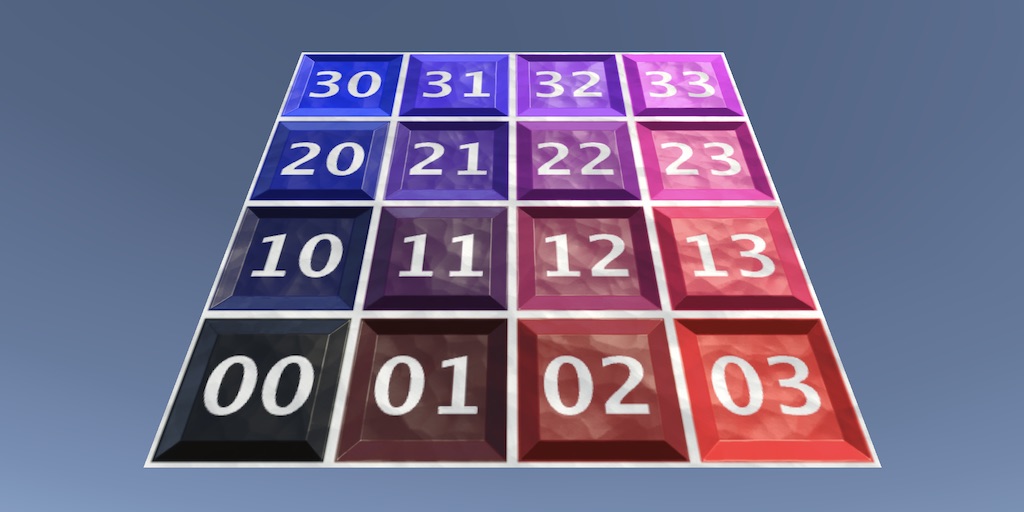
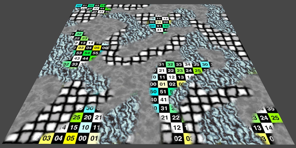
I'm trying to make a shader for my terrain to not tile so bad, as you can see from the picture, the tiling is really bad. I was told you can make a shader to make the terrain tile nicely. Does anyone know how I can do this? The tiling really bothers me when looking in the game, and it would be nice to be able to turn the tiling scaling down for nicer looking details and normals

btw if I have to make my own shader id like to use shader graph if that is possible
https://www.youtube.com/watch?v=aLCgoI0oYUo, ok so following this tutorial, I tried to make his fancy rotation node, since he makes a terrain tiling fix shader, but when i try to scale, my texture gets warped? Any ideas to fix this?

In this shader tutorial, I show how to move, rotate, and scale UV texture coordinates in Unreal and Unity. It sounds simple, but it can be tricky because of the order in which the operations are done.
Here's last week's video on UV rotation:
https://youtu.be/q62CdbKNdJQ
Here's the playlist for the whole series:
https://www.youtube.com/playlis...
In his video it just tiles
As you can see from the thumbnail, but unless i missed a step there isnt some magical tiling node that he has?
Thank you
You might want to look into this https://github.com/keijiro/HexTileTest
GitHub
Hex tile sampling test (Unity). Contribute to keijiro/HexTileTest development by creating an account on GitHub.
You don't. At least not like you're thinking.
The stencil operations are filters...they decide if the frag function gets called or not.
To do what you're asking based on stencils you'd need multiple passes. Perhaps to make an accumulated texture to then later shade based on conditionals. Or multiple materials on one object, one for red, one for green, one for blue.
Yeh I want texture based on conditional and different alpha. I'm shocked there isn't a way since it seems like a feature that would be quite useful
For many effects
There IS a way, just not with stencils.
Don't use a stencil if that's not what you want. Accumulate the data you want in a texture instead of in the stencil buffer.
Is it not just a buffer of memory with values you'd think they could expose the value in frag
How do I do it in a texture
Depends on the platform you want.
Maybe research Multiple Render Targets.
Well how many would I need
So as you're outputting "regular" stuff, you can be writing to a 2nd texture.
Not sure what you mean by platform
Some mobile might not support MRT
I need obstacles write a 1 and characters write a 2. So I need only an 8 bit r channel
Mrt??
Sure. That's one way that I can think of. Probably other ways.
MRT = multiple render targets.
https://forum.unity.com/threads/multiple-render-targets-in-urp.1068539/
Unity Forum
I'm trying to create a multiple render target shader in the most recent version of URP, based on this simple example:...
GTG, work pays the bills. Good luck.
@meager pelican when you get time to reply, is it possible to write to depth buffer's blue channel for these ids since I'm generating the depth buffer
Since it only uses the r channel for height values
I found the issue actually

My texture was clamp im assuming
well sure but what I gave is a compactly different solution that works probably better
if you end goal is to remedy the repetition of the terrain texture that is
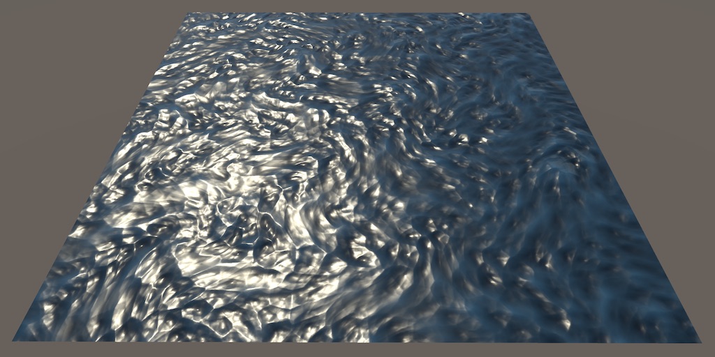
Hi, I am doing a water shader (using shader graph) and while the foam looks right when the mesh has a uniform scale of 1, it looks too stretched when the mesh has a x size of 200 and 1 along the other axis.. do you know any fix?


This is the shader (there are some subgraphs, don't know if you need also those)

This happens as the noise is based on the UV coords stored in the mesh (UV0 channel is automatically used, can see in Tiling and Offset node)
A common way to keep the tiling consistent on planes like this is to use a projected / planar mapping instead. https://www.cyanilux.com/faq/#sg-planar-mapping
Would be the Position node, Swizzle to obtain XZ and connect to the UV port on that Tiling And Offset node.
Ok thanks, it works now! Even thought the depth fade sub graph that I made (to check the intersection of the water with other objects) has broken
Now it's like the water mesh collides with everything

This is the depth fade

Is the graph type set to Transparent?
Oh ok.. now the only problem is that it seems to invert the foam with the water color

Ok I've made it work, thanks!
the solution he is working towards is the exact same as in that project from my very limited understanding
he is also making hex tiling
anyways quick question (not specifically for the guy i replied to lol)
im passing my sampled texture with UV modifications to the fragment shader, but it won't apply to the main preview. why is this is happening?

Are unreal shader graph videos relevant for unity shader graph?
Well, that entirely depends on how well you are able to translate the base concepts. A lot of things can be translated between them(though not everything.)
I saw someone above link a series on unreal’s shader graph and the series looks awesome, but it is unreal specific. Are there any decent series like that for unity? Something that is more than just “let’s build some stuff” but more teaching the system as a whole as well. I’ve written a handful of shaders and shader graphs but could certainly benefit from something a little more educational
If you're referring to Ben Cloward's series it looks like it also goes over a Unity Shader Graph example at the end? Either way it's still useful, most of the nodes are just math so isn't that engine-specific.
Though with the UV manipulation in particular ShaderGraph has Tiling And Offset and Rotate nodes which would handle that math for you.
Correct. And that’s interesting. I’ll give it a look through and see how well I can follow it
Is there a way to make a shader that not only colors a specific part of the sprite but also allows that color to be a gradient?
hey, im making a 2d pixel art water shader, and i need help. I have been following this video that showcases how it works and i would need something similiar to this except that i dont know how shaders work because im very new to this, i have most of the nodes copied exactly like he has in the video just dont know how to continue. Or I could just start over but I need help with:
- making the water transparent
- making the outline of the water
- making a wave system using the spring system thing

Heya Pals!
Today I just wanted to show off a little effect that I created for one of the obstacles in Insignia over the last couple of weeks. I was pretty happy with the result after trying a few different approaches, so here's a vlog covering the process.
Enjoy!
Chapters:
0:00 - Introduction
0:30 - Concept
1:32 - Function
2:19 - Colour Consi...
it is not unreal specific lol
oh cyan mentioned that
Oh I thought it was in unreal. The few parts I looked at were in unreal
Though with the UV manipulation in particular ShaderGraph has Tiling And Offset and Rotate nodes which would handle that math for you.
yeah he mentions that at the beginning of the whole UV thing that those nodes exist, he just wanted to show us the math behind it lol
yeah most of the tutorial is unreal, but the nodes are nearly identical between unreal and unity
Ah awesome
SDoes anyone know how I could recreate my own shader that can take a directional light (the sun) and create an actual 2d sun I can adjust like the built in Procedural Skybox shader? I have a custom shader graph I made that I like. But I'd want to add that feature.
How would I go about converting my shader graph into a shader that can be applied to a terrain? What special features does a terrain material need?
It should be possible with the Lit Graph, but probably not recommended. You'll usually get a warning in the terrain settings, saying the shader doesn't have a "TerrainCompatible" tag, that's not possible to fix in SG afaik but it could just be ignored.
If you need the splatmap / terrain layers, it's only possible to support 4 layers, but would use the same texture references (e.g. _Control, _Splat0 to _Splat3 etc).
(It's only possible for 4 layers, because normally a Terrain shader specifies multiple shader passes via Dependency shaderlab keyword but this isn't possible with SG)
Looking at the terrain shader code URP provides might also be helpful. https://github.com/Unity-Technologies/Graphics/tree/master/Packages/com.unity.render-pipelines.universal/Shaders/Terrain
not recommended by you or by the engine
I mostly mean by the engine, like this is the warning you get.
But even so, I still use SG for terrain sometimes.

btw what is the splatmap
all i want
is normal and diffuse texture
The terrain system allows you to paint different textures (for example like grass, dirt, sand, stone, whatever). The shader could support up to 4 of those layers, but not necessary if you just want the whole terrain to use a single texture.
how does the splatmap work?
Can also blend between textures based on normals, which is useful to make cliffs appear as stone. Looking up "triplanar mapping" might gives some examples to that too.
This isn't for a terrain specifically, but goes over the idea of splatmaps. https://catlikecoding.com/unity/tutorials/rendering/part-3/
A Unity Shader tutorial about combining multiple textures. Part 3 of 20.
can you read normals and textures from the splatmaps?
and like blending levels or whatever
idk exactly how the terrain texture layering works
because im def going to need multiple terraiun layers
ill read it later lol sorry im busy rn
That tutorial should give the general idea. The splatmap is masking where each layer/texture should appear.
And each terrain layer usually has multiple textures, like albedo, normal and a mask texture (containing metallic, ambient occlusion, heightmap and smoothness).
https://docs.unity3d.com/Manual/class-TerrainLayer.html
ohhh ok ok
so my problem rn, is i have no idea how to get a reference to the terrain layer data, i understand the splatmaps now
Also i AM correct in assuming that as the terrain shader, its my job to process the splatmap, textures, normals, etc. right?
Like I mentioned earlier would be texture references, _Control, _Splat0 to _Splat3, _Normal0 to _Normal3, etc. Can look at the TerrainLit.shader as an example. https://github.com/Unity-Technologies/Graphics/blob/master/Packages/com.unity.render-pipelines.universal/Shaders/Terrain/TerrainLit.shader
There's also functions in TerrainLitPasses.hlsl which may be useful to look at, to see how those textures are sampled & mixed together. https://github.com/Unity-Technologies/Graphics/blob/master/Packages/com.unity.render-pipelines.universal/Shaders/Terrain/TerrainLitPasses.hlsl
Technically, you don't have to process these textures unless you actually need the terrain painting.
Yes, the shader is always responsible for calculating the pixel colour from it's materials inputs.
and i am not a shader expert so it looks bananas to me
yes
I'm not sure you can guarantee that, particularly if you also use stencils or motion vectors.
https://docs.unity3d.com/Manual/SL-CameraDepthTexture.html
And depth is encoded, and varies by platform.
Maybe you can tell us all here what you're trying to do in general and more importantly WHEN you want to do it? Like in a post processing pass, or after opaques are generated?

im trying to draw vision cones based on depth and stencil buffers
Well, sounds like you have the 2 types defined, can you not "just' do two passes, one for each type?
im not an expert with shaders so i have no idea. was just curious if i could read a stencil value in a single pass but apparently i cannot
Yeah, it doesn't work that way unfortunately.
if it was in a different channel of the depth buffer like the blue channel so i had depth , stencilID
it would be all one pass
Oh, I get that much. Do all your platforms support multiple render targets?
@regal stag Also, how would I go about making the blending between hex tiles smoother? even with really low focus, there is still really sharp edges... ofc if you dont know its fine
first image is the weights for my tiling, and second is one of my hex channel outputs. Im assuming i want to blur the latter as well for better blending between textures. ALSO this entire question is based on the assumption that you understand the hex tiling method that was shown in the tutorial ive been following


I'm not that familiar with the method, someone else will have to help here
ok a more simple question (hopefully)
is there a good way to blend softly between the red and green channels when i go to combine them?

hmmm idk if thats what i want to do actually
nvm
but yeah very clear hexagon tearing

Some mobile won't support it. If your platforms support deferred shading, they'd support MRT since that uses MRT. According to this:
Model 3.0 (or later) and support for Depth render textures
. Most PC graphics cards made after 2006 support deferred shading, starting with GeForce 8xxx, Radeon X2400, Intel G45.

On mobile, deferred shading is supported on all devices running at least OpenGL ES 3.0.```

But you may not need it at all!  I mean there might be other ways, I still can't really tell exactly what you want, but you could maybe use layers for each "type"?  And draw each layer with another camera with different shader globals?  Or something?  IDK, maybe ask the group
```How do I support multiple colors for 'vision cones', for each object type``` or something. I fell like I/we may be over complicating this, but I'm unsure of the exact nature of the beast.@quaint grotto
hmmm, i tried downloading the solution you sent, but there are missing subgraphs that i cant find...
Hello,
I tried to switch my unity to hdrp and then back to urp but I can't get it back to my original state.
This is what my scene looks like right now, thanks for your help.

OHHH ok i fixed the issue i was having, apparently you cant mess up the order of the output hex grid channels
i didnt know that lol, now it works, and damn it looks clean
unfortunately (unrelated) turning on my flashlight reduces fps by 40
@meager pelicanlike this

i think they use stencil ids to determine what obstacle it is
If I use custom vert attributes can I pack uints into the mesh to read in the shader?
Yes
OK, but that's On or Off. You can do that with a stencil, since the "off" is filtered out and the only thing you need is the "on".
But if you want TWO of them on the same screen, one red and one blue, you'll have to do two passes to do stencils...one pass for red and one for blue.
I thought I need two because the ref decides if the frag is executed at all so I need one for solid green and one for textured no?
OK, "solid green" is one, and "textured" is two, sure.
Okay so two passes is the best I can get out of this then
Unless you know a smarter way
Sounds like it. But the good news is that it's pretty fast filtering...happens at rasterization, the frag() is only called for the pixels that pass, and that's USUALLY where all the time is spent in a shader.
Do you think I should skip using depth buffer to clip on obstacles and just use stencil
For both green, texture and clipped
That's 3 passes but no need to use depth buffer would that be more performant
Hmm....you have a separate pass for depth?
Each npc has a camera that renders depth to target texture atm
And I pass that depth to the material
OK, so not scene depth from main camera, but sight-depth from custom camera.
Yeah then I do mesh wp and depth to wp to determine if occluded
Sounds like a form of shadow casting, but in reverse.
I dunno what that is don't do shaders much
A Unity Rendering tutorial about supporting shadows. Part 7 of 20.
@quaint grottoThere might be a "cheat" or optimization you can do for those NPCs.
If you add layers for "occluders" of any type, you could have a layer that has super-simple geometry for those objects with a lot of polygons....if you have them. IDK your scene.
So when you draw that depth-buffer, you'd use the super-simple geometry and NOT the complex geometry. For the visible cameras, they'd exclude that layer.
I was planning to use simpler planes of geometry to represent the visual
Any tips, I'm struggling a bit
But can that be done if they aren't visually rendered
Ive only been able to make streams of existing data types eg vector3
And I can't seem to have multiple streams, I can put everything into stream 1 so I'm sure I'm setting it correctly but it won't let me split it up over 2 streams
By "stream" you mean UV's on the mesh?
Not quite
Each vertex on the mesh has a bunch of UV values that come across in the shader as UV0, UV1, etc. That's custom vertex attributes.
Oh
Why are they custom if they are built in
I thought custom would be new and anything I like
IDK, they're just not "stock" I guess. And the # of them has changed over time.
It's new and anything that you can pack into a float4
😉
Having said that if I could make UV into a uint that would be great
Are you sure you really need to do that? What range do you need your uints in?
I'm trying to bit pack data and the uvs as float32 is causing issues
Thanks 🙏
No idea how I can fix this pls?
Did you put your project on version control?
So the UV data is in a float4. That can make packing a 32 bit uint really easy. You could just put 8 or 16 bits of data into each float and put them together later using bitwise operations in the shader.
So you'd do
    uint packedG = uint(color.g * 255) << 8; // shift bits over 8 places
    uint packedB = uint(color.b * 255) << 16; // shift bits over 16 places
    uint packedA = uint(color.a * 255) << 24; // shift bits over 24 places
    uint packedColor = packedR + packedG + packedB + packedA;
(I shamelessly stole this from Ben Golus from this post: https://forum.unity.com/threads/encode-float4-rgba-to-uint.695176/)
That's storing 8 bits in each color channel. You can probably get away with 16 bits and only two operations rather than 4.
I think the post was about the other way around, but you get the general idea.
@indigo ginkgoYou're sure you need this per vertex?
I can get the packing working but the data type is still fp32 isn't it?
This question is for me?
It's for baking material properties into the mesh so I can merge the meshs into one material and save drawcalls
I've got the texture combining part working ok
Maybe I should be doing some texture based lut...
IDK what "the" is...which you're referring to.
I mean, in the shader it's a float4.
that's 4 32 bit signed floats. (128 bits total)
In C#, it's also 4 floats.
UV by default is vector2 of 2 fp32 values
I know I can make it vector4 but it breaks some stuff in the pipeline
Yeah, OK. Still 64 bits then.
But if you can use a texture, I'd do that. IMO.
I suppose I'd like a quick fix for now
It depends on what you need. "Splat maps" and other such techniques are common.
Which is making the fp32 a uint
Bust it up into two, and use bitwise operations.
What does bust it up mean?
Sorry if this is a stupid question
I might be missing something simple
In C#, you want to encode a bit value, so you have some uint, yes?
If I bit pack 8bit white or black into fp32 it ends up all 0000 or 1111 and that causes issues with sending the mesh data to the gpu
I think it counts as nan or infinity so the number gets lost
Yeah it's uint in c# but then it gets set back to fp32 when it's applied as uvs
Yeah
How many bits did you say?
No, float32's x 4
So that's 128bits?
Yeah, that's a problem.
What I was suggesting is storing whole numbers in 4 floats 16 bits worth of precision, but that still only gets you to 64 bits in one float4.
That way you don't get a binary representation in the floats, the floats are just floats. The binary comes back OUT OF the conversion to the uint. Then you don't worry about NaNs and stuff.
Like reading a hex dump that is two bytes wide
So you'd have a float (maybe the .a part of a float4) that represents values 0 to 65535
And you'd have a float that represents the multiples of 65536 to whatever, etc.
Will the whole numbers not fall foul of fp errors?
you're only storing 16 bits per float as a whole number. It can do that.
Because they're not binary, they're floating point whole numbers.
If you wanted to store the value 0x00000000 00000000 00000001 00001111
in the float4, you'd store it as (0, 0, 1, 15) and in the shader you'd do
uint myInt = uint(uv5.a) + (uint(uv5.b) << 8) + (uint(uv5.g) << 16) + (uint(uv5.r) << 24);
But that's only for 32 bits, not 128 of the damn things.
But that's for storing 8 bit whole numbers.
Now if you put 16 bits worth of values into each float, you can double that to 64 bits encoded in a float4 and still I don't think you'll hit your Nan issue since you're only storing whole numbers and they range from 0 - 65535, which is easily represented in a float32. The trouble comes in when you try to store too much in one float32. It's signed and also has those special values.
You'll never stuff 32 bits of data into a float32 without hitting those values, as you've observed.
So it's probably easiest to use 16 bits of resolution.
and to do what you're asking you'd need TWO float4's....16 bits per channel x 4 channels x 2 floats = 128 bits.
Ok she's asleep on my lap 😅
Yeah I see. I think I'll implement that then look at the splats
Splats is just a texture storing information?
Im baking materials to arrays so have the slice index saved in the mesh
I assume I can use that as a value to sample the splat
There is a texture format that is binary, but it maxes out at 64 bits.
Not all GPUs support all texture formats, be warned.
https://docs.unity3d.com/ScriptReference/TextureFormat.RGBA64.html
Yeah, but that's not your 128 bits, right? Because you shouldn't need a 128 bit slice-index
hey, so I have been following brackey's tutorial on how to make an outline shader, but i cant really figure out why but the outline doesnt work like it just doesnt show itself in the subtract preview and when i apply the shader material to the object (this is a 2d project) its not even the color its supposed to be. Could anyone help me with this? (im a noob at shaders)


Thanks to NVIDIA for sponsoring!
Learn more about NVIDIA Studio► https://nvda.ws/38AaA8K
Razer Blade Studio laptops► https://www.razer.com/studio
In this video we create outline effect using 2D Shader Graph!
● Learn more about 2D Shader Graph: https://youtu.be/5dzGj9k8Qy8
● 2D Glow Tutorial: https://youtu.be/WiDVoj5VQ4c
● Get Gothicvania Ch...
It took me time to understand too, I mean it's hard to communicate that level of detail back and forth.
If you find a better method let me know.
Find a more recent tutorial. I love Bracky's but the shader graph stuff is too old now.
See here:
https://alexanderameye.github.io/notes/rendering-outlines/
https://bgolus.medium.com/the-quest-for-very-wide-outlines-ba82ed442cd9

Different techniques for rendering outline effects.

thanks
At pc now & testing it out
I'm still very interested in knowing how the custom vertex attributes work too
but I guess that can wait
Hey everyone Im not sure should I post this here or in #archived-lighting but here we go

this is the model in unity
and this is how it should look like

what Im doing wrong why unity is polishing my model?
In lighting
The cause is ambient lighting, reflected sky and likely also smoothness defaulting to 0.5 when the materials are generated on import
is there any way to fix it? @grizzled bolt
Hey does anyone know of a shader that would work for VR hands that doesn't have the depth issue when making a fist. I just need to be able to fade it i and out
Also put a reflection probe into the center of the room (if only using one, or spread some around). Depending on the lighting settings you may have to bake lighting.
thanks for advice
Any idea how to achieve this look? At first glance I thought its simply unlit shader but the more I look at it the more little shadows I see, some how this picture seems lit and unlit at the same time lol

I think unlit with AO might get you most of the way there - most of the 'shadows' occur near crevices on 3d objects (e.g. the tree blossoms)
Is there an easy way to rename a shader? If I change the name of a shader in the .shader file, but keep the files metadata the same, will Unity be clever enough to carry on using the renamed shader? (in particular, for assets in different projects)
that must be it you are right! thank you a lot sir
Does anyone happen to know why Parallax Occlusion Mapping doesn't seem to displace the material at all in scene view?
i can see the displacement happening in the preview but nothing happens in the actual scene, using the standard Parallax node works absolutely fine and shows the displacement in scene...

Hey there, does anyone know how I could change the colour of only the white parts of the image on the top? Basically, I want the plant and dirt part to stay the same but I want the hand to be set to the colour that they player choses. As you can see in the image I tried doing a mask but it did nothing except cause a lot of weird glitches like the top of the leaves changing colour.

You'll probably want to Lerp the base map to the color using the mask as the Lerp factor, rather than multiply and add
I figured out a really weird work around using a node called replace colour. It doesn't completely get rid of the white but from the way I'm using it it makes dark colours have white outlines which is nice. Thanks for the info though!
The graph you posted would also work if you removed the hand from the first texture (leaving black pixels)
How could I make a 3D "dark fog" effect? I have some cars that exit from a tunnel that the player can't access (which is like a simple quad with a black png for the tunnel) and I would like to make the parts of the car that are still in the tunnel really dark.. something like a black fog inside the tunnel (I am using URP)
you'd probably have to look into depth textures for that
or just use environment fog
Hi ! I have basic (i think) shader graph question, given a grayscale texture (a Mask with one Channel basically) how can i remove values under x and over y ? For example a perfect black to white gradient and i only want what's between 0.4 ans 0.6, outside this range i need values to be replaced by 0
it sounds simple but i cant figure out what nodes combinaison to use
i tried playing around with step, smoothstep, clamp, lerp but at best i remove one side of my min/max but not both
That's because it's a two-step process. Step black to color, and then step color to black. With appropriate thresholds for each step function.
how do I change the intensity of an HDR color via code?
for this on my draw distance influence where can I change the draw distance

Colors are in 0-1 range, HDR colors are colors multiplied by intensity value
ah yea, I figured it out! but thanks~
https://giant.gfycat.com/PointedAggressiveEchidna.mp4

Hey, maybe somebody knows how to solve shaders errors? These errors comes after I trying to built the project

@tender tusk Please do not crosspost
Ok deleting it
I know that lit shaders are affected by light and unlit shaders are not, but what is the difference between sprite shaders and the normal ones?

Sprite shaders would support sprite renderer features like masking and 2D lighting
ty! So If I would want a 2D sprite to be affected by a 3D spot light, I would need the lit shader graph?
Or is that not possible? since it's not working
And would it be possible to have light affect a raw image attached to a canvas?
I've been stuck on this for a while now
I assume so, though you must not be using the URP 2D Renderer since it flat out doesn't support any non-2D shaders for whatever reason
In my experience 3D shaders at least mostly work on sprites but I don't know what all of the drawbacks are
I haven't ever tried to get lighting onto canvas images or heard of anyone doing that, but I assume it'd be impractical, if even possible
I'm having an issue setting global shader values: It seems like CommandBuffer.SetGlobalInteger doesn't work (or at least, it's value isn't being passed to the compute shader I'm targeting)
Hello I have a problem with a UV distortion effect, I can't do it correctly, it changes the scale of the texture and it comes out on the sides (I took example on a tutorial (https://portamedia.studio/quick-tip-simple-uv-distortion-in-unity-shader-graph/)
If someone can help me to make UV distortion in shader graph, thank you very much! ❤️

Instead of the Lerp, take the noise output, Subtract 0.5, Multiply by Distortion Intensity, and Add with output of Tiling And Offset (or Offset input)
Also it works, but shouldn't need the Split and Combine at the top. Just multiplying the Panning and Time works fine (like you're already doing with distortion speed at the bottom)
thanks ❤️ I made the change, is that right? @regal stag

I'd put the noise into the A port on the subtract node. But yeah looks okay. It's not doing the "scaling" anymore at least.
Though the result looks like it's shifting diagonally a bit, that might be because 0.5 isn't the average value of the noise, so may need to try some other values / alter texture ranges / import as non sRGB. Not sure.
Could also try a noise normal map / flow map instead. Or use Normal From Texture node.
May also want to scale down the original texture to give some padding to distort into, since if the texture goes outside the quad/mesh it won't be rendered. Can either do that by editing the texture, or do something like (UV - 0.5) * 0.9 + 0.5 + distortion as the UV.
Also if you don't want it to repeat, change Wrap mode on texture to Clamp (or attach a Sampler State node to Sampler port on sample)
I managed to get a result but I have to cheat with the values, I don't have much control. thank you! ❤️
I would be interested if you have links explaining how noise normal map, flow map, normal from texture node, staging these nodes / technique work. Maybe you talk about it on your website ? thanks @regal stag
Looks good.
I just meant those as alternative ways to handle the distortion. e.g.

Though Normal From Texture samples the noise texture 3 times so is more expensive. But that could be swapped out for a proper normal map instead and then it's only one sample again.
I thought it might make the distortion look a bit better, as when you're adding with just the float/R output it's adding to both axis so only really distorting diagonally. While with a normal map it's distorting in all directions. But with strengths this small it's not noticeable anyway.
nice that gives me other variants thanks @regal stag ! I could even make the normal map myself to reduce costs (I guess)
And the flow map is this a technique that is done with a node scripter?
Yeah flow map isn't built in, but would be something like this : https://catlikecoding.com/unity/tutorials/flow/texture-distortion/
Also example graph below.
But might not apply that well in this scenario, idk.
I mostly mentioned it because a flowmap texture is similar to a normal map but with just RG channels (which is all we need for texture distortion)

A Unity Flow tutorial about distorting a texture to simulate flowing surfaces.
Thanks 
I have a shader that does a kind of liquid possibility with particles but I need it rewritten is there a place to put up job offers like this
does anybody have any clue how i could come even close to creating an effect like this game in unity:
https://www.youtube.com/watch?v=1yqSxMqHnOI

i have 0 experience in creating shading effects and dont even know what to research/look up for this sort of effect
its like gritty, grainy, but looks almost hand drawn/ink
Maybe some kind of thresholding effect, some noise, and some color quantization?
Hello, I have an issue which I assume is shader related.
I have a single mesh as an fbx (it has animation), this fbx has several planes to form a 2D asset in 3D space.
I "baked" the alpha channel within the image texture I'm using for the model, a single atlas for the whole model.
Problem: I don't know why every time the meshes, all belonging to the same object (all the model is one single mesh), when overlapping one another, some parts of the topology disappear, like the hair for example.
What gives?
I send some images regarding my texture and my material settings.
Thanks

I'd like to prevent the time sine from going to zero or 1...any nodes that can help me with that?
Trying to do the shader tutorial thing where you make the flag wave
And I’m pretty sure the tutorial is out dated because it just not work how they say it will work
This is what I have down

cant you share a screenshot instead of a shot of the screen? 😄
Sorting of transparent objects is tricky.
But it looks like you don't need partial transparency, so should switch to Opaque but enable Alpha Clipping to clip/discard pixels below a certain threshold instead.
It goes from -1 to 1. Perhaps you want to Remap it? Or just Clamp?
Depends what you are doing. Might be better to ask in #archived-urp though, this isn't really related to shaders.
Looks fine from what I can see. But make sure the mesh you apply it to has enough vertices to displace, the correct orientation (since y axis is the one being displaced), vertices have an appropriate scaling, and UVs set up.
The default unity Plane mesh is probably a good one to test it on.
Make sure you also save the graph (button in top left).
hi, i am working on VR dev as junior tech artist, i already learn shadergraph, and want to learn about compute shader, is it worth it? and what make it different? isnt it basically just make you have the ability to use GPU in almost everything?
It's worth it if you intend to create custom rendering features that can run fast.
i see, is there any other benefit?
i mean sure, it's very helpful but learning compute shader is definitely not easy
It's also useful in realtime and offline simulations
Any computational task that the GPU architecture is a good fit for (a huge number of small, repetitive calculations in parallel) so the possibilities of "what it's good for" are pretty much endless
I'd go googling for examples of what people usually do with it to get a better picture
i see, thank for the information, i just want to make sure, because i already learn the basic of compute shader and it's very confusing
If your experience is with Shader Graph so far, you'll probably want to learn shader languages next
Compute Shaders are further ahead from those both
hi
I installed a map to test, and here is the result nothing at all for the textures
the dev says that
Note: When importing the package I noticed
All the shader materials show up pink in
the project editor, Im still working on why
this would be. Though they all work fine in
scene as is and if you want to fix the pink
colour just reapply the shader to the
material.
before exporting it to FBX I would like to have the textures but I don't know how to do it

Check the package compatibility with your editor version and Render Pipeline

that the problem ?

It could be a problem but you haven't really stated what you're trying to do or how
If the render pipeline is incompatible with the assets you'll need to change the assets or change your project
But is your goal to make a project work with a specific RP or the assets work with a specific RP
idk just download unitypackage and i have only readme
______________________________________________
Note: When importing the package I noticed
All the shader materials show up pink in
the project editor, Im still working on why
this would be. Though they all work fine in
scene as is and if you want to fix the pink
colour just reapply the shader to the
material.

what is simple noise on shader? is it perlin?
If you're referring to the shader graph node, it's multiple layers/octaves of value noise.
Can i do it on CPU with unity mathematics?
i have it on my game. It has 2 colors and noise blends both for ground texture

Now i want to do the same for grass meshes
Set the grass mesh color based on same noise (for same world position)

Like this but i don`t use terrain
I'm trying to transfer Shader code from shadertoy.com to Unity, but when I transfer it to Unity I just get a black screen. I tried changing almost all variables in the functions to static, but that didn't work either.
I'm getting no errors in Unity either
needed a fairly lightweight gore shader, pretty happy so far
any optimizations, please feel free to suggest, fairly new to shader graph

Not sure where I should paste my code
on a mesh
Hastebin is a free web-based pastebin service for storing and sharing text and code snippets with anyone. Get started now.
Does anyone have any idea how much more processing intensive it is to render both sides in a shader? Do I need one-sided and two-sided variants?
Is there anyway to make a shader in urp only replace the value on the stencil buffer if nothing is in front of it?
good questions that I have in addition to this, does the shader compiler automatically optimize stuff
like the C compiler does
It basically doubles the geometry you're rendering so only use it when absolutely necessary
Is it possible to edit another texture in an image effect shader? I tried to compile the following code in an image effect shader, but it gave me this error message Shader error in 'Hidden/TestShader': maximum UAV register index exceeded, target has 0 slots, manual bind to slot u1 failed at line 42 (on d3d11)
            uniform RWTexture2D<float4> _Tex2 : register(u1);

            fixed4 frag (v2f i) : SV_Target
            {
                fixed4 col = tex2D(_MainTex, i.uv);

                _Tex2[int2(i.uv * 1024.)] = col;

                return col;
}```At the moment, I'm just trying to set pixels in _Tex2 to pixels in _MainTex, just to see if I can edit a second texture using an image effect.
Trying the code without the : register(u1) part yields this error message: Shader error in 'Hidden/TestShader': maximum ps_4_0 UAV register index (0) exceeded - note that the target doesn't support UAVs at line 42 (on d3d11)
Is there a way to convert flat image to distance?
Like this:

For some reason I can't access it at all
Hi all, I would like to create a fade effect on the edge of a sprite mask, after some research I saw that it could be possible with Unlit Shader Graph but I am completely lost... If you have a solution to create a fade effect I'm interested!
Plug this in to your Alpha

Swap noise with your texture
Swap time with your float fadeTime (0 to 1)
Not just with shaders, but there are tools such as this
https://catlikecoding.com/sdf-toolkit/
Thanks for your answer I tried to implement it but unfortunately my level on shader is close to negative 🥲 I finally found an asset on the asset store that does what I wanted.
Its a procedural map, ideally it could be done in shader if possible.
I am thinking of expanding the shape, then use shader graph's distance(original, expanded)
But expanding it is a challenge too while keeping sharpness
Or maybe adding distance to edge
Distance is just the difference of two values
Fragment shaders don't really have knowledge of adjacent pixels so it's not a trivial problem at all
https://www.shadertoy.com/view/4syGWK something like what's done here may work but it's beyond me
Ah, so its like blur
How do I pass down array in HLSL?
I am getting syntax error.
float SomeMethod(float2 UV, float2[] vertices) // syntax error: unexpected token '['
{
}
@astral pecan https://iquilezles.org/articles/distfunctions/ since your shape is procedural, another option is to describe the shape itself with an SDF function so you don't need to try to generate it afterwards
Hi guys, does anyone know what I have to do in order to make my shaders work with deferred setting in URP?
I found basically nothing online 😦
Your first option should be to make the shaders in Shader Graph so it'll take care of that
If that's not an option I believe this guide is the best one out there https://www.cyanilux.com/tutorials/urp-shader-code/ also goes over deferred rendering
uh already done that, I've got all my shaders done in shader graph (with few lines of code for custom functions in hlsl). But this doesn't seems to change anything
for example: if I have a plane with my shader, and I place 10 lights above that, the lights shown will be maximum the number set in the URP setting asset, as if the rendering was NOT set to deferred (it is). But if in the same scene, with the same lights, I place a URP lit shader into a plane (or that same plane), then the plane will take all the ten lights, ignoring the lights limit, as it should with deferred.
So I guess it must be a problem with my shaders, still linked to the lights limit.
The likely explanation is that the shader is transparent
Is it?
some of them, yes
but not the terrain (the plane where I tested)
it's... unlit, also
thye're all unlit - maybe that's the problem?
I also use custom lighting to apply additional lights, from a script taken from a video online and slightly modified:
however I can't find any reference to a forward renderer or a light limit... so...
The shader would have to implement deferred lights as well to support them, I expect
Deferred rendering also doesn't support transparent materials at all
if the transparent objects behave as in the forward renderer, then it's a smaller problem (it would be bad in rare cases, but not in most of them)
but... it behaves in the same way with opaque objects, like the terrain
and that's a huge problem
so, any guide to implement that..? I really found nothing online
No videos, no recent forum posts...
The one I linked is probably the closest there is
Transparents fall back to forward rendering
can unity surface shaders find out the dimensions of a texture?
By using the HLSL GetDimensions function : https://learn.microsoft.com/en-us/windows/win32/direct3dhlsl/dx-graphics-hlsl-to-getdimensions
Gets texture size information. The syntax block shows all the parameters that are possible in the method declaration. The table in the Remarks section shows which parameters are implemented for each texture-object type.
Tried also the |TextureName]_TexelSize macro ? https://docs.unity3d.com/Manual/SL-PropertiesInPrograms.html
I think thats the same 🤔
do you know which one would be best?
I've got another question, I'm baking some textures to use as LUTs
@thin crater @grizzled bolt Custom lighting can't be done in deferred, as the shading/lighting is done in a specific pass after GBuffers. All you can do is alter how the GBuffers are filled.
Unless you want to dig into the URP code and add some branching in the deferred rendering funcion
but I'm not sure what to do with regards to them be power of 2 textures
for example a LUT texture might be 12 x 72
Maybe the macro is easier to use, as it is declared more or less automatically
will do that then, thank you!
So ... 6 times a 12x12 texture ?
I'm just trying to understand the LUT format here ^^
oh its not the colour grading luts
Im just storing data in rgb values
to use in the shader
But worst case, you can just use it as uncompressed not power of 2 textures.
It is small enought to not have a big memory footprint, and you probably want uncompressed anyway to avoid loosing data
yeah def uncompressed
I'm not 100% sure what happens to uncompressed non power if 2 textures, do they still get sent to the video card?
or do uncompressed textures not need to be power of 2
Yes, they still get to the video card 🙂
IIRC, it's more about memory optimisation, as a non PoT texture won't allow to fill the video memory as efficiently as only PoT ones
So is there a way to code a shader graph that works with deferred setting on?
Technically, yes, but not without modifying URP source code
Or if you only want to alter the GBuffers (understand PBR surface properties), it should be fairly straightforward
thank you Remy you've been a big help
Uhm... And if I want to have unlimited lights per object with a custom shader? Is it straightforward? Are there docs?
My problem is just the light limit per-object, having a huge terrain chunk limits the number of lights that can be placed above it, to 8
And that's a big problem, some mobs will have lights on them, and the player might want to build more than 8 light sources in a single chunk..


New versions of URP have forward+ rendering path which may work with custom lit shaders, though I'm not familiar with it
I've got URP 13.1.8, seems to be the latest. I'm also using Unity 2022.1.3f1, if needed I'll try to upgrade to Unity 2022.2.10f1, that's the latest 2022 build.
Forward+ is in 2022.2 Beta, URP 14
How about using a gradient or a 1D texture ramp to control the colors ?
Does it have a maximum light count?
is that a beta? I can't find any 2022 beta, only 2023 beta

2022.2 is out of beta
so it has not URP 14 with forward+, right?
I mean 2022.2 beta was when the feature was released
As you can see on the doc page, there is still light limit, per camera
oh man, so it would fix my problem! Thank you!!
Now the problem is upgrading, last time I tried that I had many, many errors and I had no clue on how to fix them 😅 but that's another topic
thanks a lot @grizzled bolt @amber saffron
it's 256, pretty high, and if the lights that are not in the camera range don't count then it's not a problem (what I mean: if I have 400 lights in the scene but only 200 are in front of the camera and they're all rendered, then it's not a problem for me... but also with 256 lights per camera, breaking this limit will be pretty hard)
Experimenting with some post prossesing god ray shader, but for some reason these black dots start to appear and I don't know why. ```cs
fixed4 col = tex2D(_MainTex, i.uv);
float2 texCoord = i.uv;
float2 deltaTexCoord = (texCoord - ComputeScreenPos(float4(SunPos.xyz, 0)).xz);
deltaTexCoord *= 1.0f / NUM_SAMPLES * Density;
            float3 color = tex2D(_MainTex, texCoord);
            float illuminationDecay = 1.0f;

            for (int i = 0; i < NUM_SAMPLES; i++)
            {
                texCoord -= deltaTexCoord;
                fixed4 s = tex2D(_MainTex, texCoord);
                s *= illuminationDecay * Weight;
                color += s;
                illuminationDecay *= Decay;
            }
            return float4(color * Exposure, 1);```
still looking for help on this. I tried using #pragma target 4.5, and it got rid of the error message, but I'm still unable to modify the pixels on _Tex2.
by the way I made something that looks similar to what you're looking for

I did this by taking each pixel's distance to a point and setting its brightness based on a function that looks like this.

In order to make it separate into bands of red, green, and blue, I just multiplied the input of the function above by a number between 0 and 1 for each color channel, with the number being less for green and even less for blue, like so:

hope that all makes sense 😄
here's the function I'm using btw, it doesn't have to be exactly this, this is just what I decided on in the moment lol

i love desmos :)
I upgraded to new URP 14, and it has Forward+! However, there's still a problem: lights flicker a lot, and it's not really usable
They flicker like that: https://forum.unity.com/threads/urp-forward-lights-flickering.1373658/
Unity Forum
Hi, I just changed URP render path to Forward+ and all the lights are flickering now.
I'll edit this thread with the video showing this issue.
Unity...
That's my project; it flickers so hard I should put a graphic warning
Thanks, I was able to produce similar results as well!

Well, since others are having the issue at least it's not specific to your project, and probably will be getting fixed
Maybe filing a bug report of it will give them more data to work with
but not everyone is having it 😦
so maybe there's a workaround
also, it only does it with my custom shaders, not with lit/unlit URP shaders
Custom shaders made with Shader Graph?
That could be another reason to file a bug report, so they can potentially update the system to support custom lighting Graphs
I have no clue how to file a bug report 😦 I'll look for it
Maybe it's intended to work with the hlsl lighting functions, maybe not
But it's worth doing anyhow
but I need a solution.... if there's one, maybe I'm still getting something wrong
maybe I'm using something outdated
Also, sometimes stuff just breaks when you upgrade a lot
It's best to make a repro project just showing the issue for the bug report, and by doing that you'll also confirm if the problem carries over to a freshly created project
Did the Shader Graph package update automatically when you updated Unity/URP?
If it doesn't carry over and you can't reproduce the problem, that means you have the means to work around the bug yourself
Why is there no "Create > Shader > Empty HLSL"... or similar?
How are we supposed to create HLSL shaders from within the Unity interface?
You mean something like "Create > Shader > Unlit Shader", but one that uses HLSL instead of CG?
no, a button to just create an empty HLSL text document
cause I'm lazy
That is very lazy indeed. Is it not convenient for you to create these files in your IDE?
I'd rather do it in Unity & double click to open up - that's what I do for everything else
don't wanna have to browse for the correct file path of my project in the "save as" menu
maybe Unity editor scripts can help me out with that
edit: ye, I'll just do it with editor scripts, seems very doable
Well, you can always create you own menu items:
[MenuItem("Assets/Create/Shader/Empty HLSL", false, 1)]
private static void CreateNewAsset()
{
    ProjectWindowUtil.CreateAssetWithContent(
        "Empty.hlsl",
        string.Empty);
}
yep, thanks
Hello :),
i am facing some weird behavior with my shader, when i put it on plane i am getting some whole midle , as you can see on second pic wireframed one edge is disolved, Any idea to solve it plz?


Can somebody tell me why im getting this error?
Im using a lit shader graph as part of the URP
im using a custom function with the following code https://pastebin.pl/view/829a15ef
I dont understand why its not working, I tried following the tutorial and then just copy pasting from the patreon directly and both dont work

Pastebin.pl is a website where you can store code/text online for a set period of time and share to anybody on earth
how can i use a image on gameobject which is invisible so I see only the image in the game (its a bullet impact)
I dont quite understand. Why dont you use decals?
sorry i'm a beginner whats this?
I want that if i shoot with my weapon, the image of the bullet impact is shown in the game
It does sound like you're describing decals
how to use them i cant put the image on an empty gameobject
Search online for Unity's decal systems, see if they fit your needs
Not sure how decal works if there's no renderer to project it on
Having a fully transparent renderer and enabling Affects Transparent in the decal projector settings would work, In HDRP at least
They mentioned that the other gameobject is invisible, in case you missed that
Could also be looking for sprite masking
Hard to say
Right, I didnt even consider 2D
anybody have any idea on why this is happening
It says it's at line 193, it might just be so far down you havent even checked there
Does #pragma multi_compile not allow global variables in compute shaders?
trying to use it to define a texture as a float2 vs it being a float4array(built in motion vector vs hdrp motion vector texture)
if somebody knows something?
i have like 36 lines of code
it takes me to the unity code manager or smth like that
Yeah, but you might've just coppied the upper part or something like that
i downloaded the file from thje patrion
Might be something completely different tho
and the shader graphh
yeah I downlaoded all the materials they used for the tut and made sure to hook everything up and it doesn't work
hello, im new to hlsl. Im trying to make a shader that takes height map information and uses it as a mask for a texture. Any help on this or if you can point me in the right direction . Thanks
I forgot to put the URP as the pipeline to use for rendering 
i spent 3 hours trying to figure that out
I feel u lmao
Hi! As I said in some previous messages, I upgraded to Unity 2022.2.10f1 and URP 14. My goal was to use Forward+ in the settings so my custom shaders could use an (almost) unlimited light count on them.
But the problem is that when I enable Forward+, the lights starts to flicker.
Digging into the problem I created a fresh new project (so if it's a bug I can report it), and I imported all my shaders. I managed to create a minimal shader with just the bare minimum to be shown and reproduced the bug.
So, this is my current shader.

The problem seems to be in the CalculateLightingRamp subgraph.
This is the subgraph.

(if it's not clear, it's the second node in the main shader)
I've noticed that if I link the main light diffuse to this CalculateLightingRamp node, the cube flickers like in my main project. But if I set a constant value - like light intensity, or just a float static value - then the cube with the shader will not flicker anymore (but will have only one light everywhere in the cube, as if the light came from every side of the block).
This is the calculateMainLight subgraph, if you want to see how I calculate the diffuse value

And that's the custom function

I have absolutely no clue if that's a bug, or if it's intended to be, because docs for Forward+ is very scarce and very few posts have been created for it 😦
Make sure to include that info in the bug report summary
I doubt many here can help with that
The number of people who've tried to use custom lighting with URP's forward+ renderer so far might very well be in the single digits globally
that makes me feel somewhat special ahahah
I'll report that now, hoping to get some help
Im using a height map, and "catching" certain ranges of 0 - 1 values. Im trying to blend in and out from that range. my goal is the second image or atleast something similiar


The first image is what i have so far. Looking for hlsl solution . im using URP
It sounds like the problem is with the Diffuse, not the lighting ramp then. I would test each part of the diffuse calculation. Check the outputs of the CalculateMainLight on their own - see if the direction flickers, or distance atten, or shadow atten.
any advice on how to do it? I'm not good at all with hlsl 😦
I also thought the problem could be on diffuse, but I was not sure....
https://www.youtube.com/watch?v=E4PHFnvMzFc&list=RDCMUC7M-Wz4zK8oikt6ATcoTwBA&index=6 @thin crater good information on hlsl , if this video doesnt have it one of her other ones will most likely contain what you need
In this final lecture we dive into normal maps, tangent space, height maps and image-based lighting
If you are enjoying this series, please consider supporting me on Patreon!
🧡 https://www.patreon.com/acegikmo
00:00:00 - Intro
00:01:17 - Recap
00:10:34 - Multi-light support (assignment 2)
00:14:48 - .cginc include files
00:21:18 - Multiple pas...
covers some lighting/shader stuff in depth
Is there anyway to make a shader in urp that only replaces the value on the stencil buffer if nothing is in front of it?
Output each of those ports to the Base Color, might be easiest to copy it inside the main graph to do that). That's usually the easiest way to start debugging a shader
As long as the shader is rendered after other objects, and uses ZTest LEqual it should do that