#archived-shaders
1 messages · Page 34 of 1
I think compute shaders are specifically intended for that kind of purpose
You can also use Blit for this.
I just got the shader from a big popular sprite shader store-package, I don't actually know what it uses to work.
I'm new to Unity. Why's my shader graph material pink?

Shader error, missing or invalid graph target or misconfigured URP/HDRP
How do I know if URP is misconfigured?
Or how do I know I have an invalid graph target?
Check the pinned messages of #archived-urp, find the installation instructions and make sure you've followed all of them
It's very common to miss some of the steps
If that doesn't work you can check what targets the graph has and make sure there's one for the active render pipeline
https://docs.unity3d.com/Packages/com.unity.shadergraph@12.1/manual/Graph-Target.html
Hey folks! I have a question on how I can store an attribute on mesh in maya and use it in shader as a mask?
Would a mask texture or vertex colors do?
I don't want to use textures but I vertex colors work. How do I set them up? I have no idea where to begin
Hello Everyone i have a texture that i want to apply to all my walls. But the tilling needs to be different on each wall how do i go about that? I tried looking online but most of the post were over a decade old
most materials expose tiling and offset controls
also can control that in the models themselfs when creating them with UV's
Yeah i tried messing with the Tilling offset on a specific wall but that changed all the walls at once
I figured i have to go the UV route
thats only if each wall uses the same material
They do have the same material
I ended up just make a script that changes the tilling
Idk if thats best practice tho
yes thats why it changed for all walls
Yeah that makes sense
I wanted to know if i can just the specitic material props on specific walls if they have the same material
It seems weird to have to make a material for each wall
don't think so
Yeah which is insane to me
The script ended up working so i wasnt too stressed about. I appreciate u talking to me tho friend best of luck to u on ur game dev journey
the script is working since its creating a new material instance per object and modifying it
that sounds bad for performance....also i ended up just making the thing i didnt want to in the first place lmao
i was trying to avoid making multiple materials and ended up doing that anyway lmao
F@)# i thought i had it figured out
Oh i see it in the inspector now.... It says Texture (Instance)
Ill do some research on the instance part
accessing .material creates a instance
.sharedMaterial uses the existing mateiral asset
other way of doing it per object but not creating new material instances would be modifying the mesh data and adjusting the UV's there
How would i be able to access the mesh data in unity tho? Im sorry i dont mean to ask alot of questions but im not super familiar with UVs
you reference the mesh and there you have then all the data
Aaahhh i see
in a shader graph, is there a way for it to grab data from somewhere in code? like, for example, an array that represents squares for paths to be placed. can a shader on a terrain grab that data from the script somehow?
Gonna figure out the difference between Mesh and Mesh Filter ill look at the documentation and come back if i need anything thank u both so much
you can pass data from a script to the shader
how would I start to do that? I'm still new to shader graph
reference the material the shader uses and then use setTexture, setFloat, set... to pass over some data
in this case I worry I'd have to make like 4 million floats to represent the array of size I want
my array is 500x500 atm so not quite 4 million but still
unless there's a data type in a shader that an array can map to?
in hlsl you just straight up have arrays, but in shader graf I am not sure..
hmmm
maybe there's a better way of storing that data, then
I am trying to make it so that the player can place paths on a grid, and the shader respects the paths placed and draws the appropriate texture
so my first inclination was "make an array the size of the terrain size" and have the shader read the array values and sub out the texture I need
but if there's a better way I'm all ears
why would placing paths need to be in a shader?
mostly because I am using a shader to do the rest of the texturing
if you just need to place some textures in a specfic order next to each other, why does the shader need to figure out which to pick? To me it sounds like you can do that on the cpu
what does "do that on the cpu" mean in this context?
sorry, I'm a little out of my depth here. do you mean just apply the texture using standard terrain stuff and forget the shader?
unitys terrain system? I thought everything was on a grid?
like a 2D grid
well, sorta - the paths are on a 2d grid because its a top-down game and storing that info in a non-overlapping way means a 2d array of ints where the values represent predefined paths and 0 represents no paths
the terrain itself is sculpted during my terrain generation, a shader handles the texturing, and then I wanted to be able to walk around in-game, place paths, and see them visually show up, yanno?
so my thinking was there might be a way to translate the array of paths to some sort of data the terrain shader could read, I could grab the rounded x/y of the world pos, associate that with the path index, then display the texture that fits
but it seems like shaders might not handle that kind of data well? I dunno. not really my area of expertise
to me it sounds like you can figure out which texture to place on the cpu and then pass the correct texture to the shader
c#
that's an unconventional route, I like it!
ah, hmm, but how would the shader know which texture to grab?
like, I translate my array of ints to an array of textures. how does the shader know which texture cell to read from?
the shader isn't grabbing any textures you are giving the shader the textures you want the shader to have
how does the shader know where to place them?
the shader handles my other textures by reading data from the world position - angles to do cliff textures, heights to do grass vs sand, etc
I'm not sure how to get the data I'm looking for in a place where the shader can read from it
you can get position from the player for example
actually
like, to be clear, if this is literally impossible for a shader to do, that's also an answer, I'll figure out another way of handling this
to me it sounds like you are making some sort off texture painting tool.
yeah! sorta!
well thats a thing you can research about now, how people do these tools, cause they can be quit specific on their own
Lmfao just looked up a tutorial and made one from scratch
Is there a way to add shadows from multiple lights?
Hello, could someone help me converting it to URP?
// Upgrade NOTE: replaced 'mul(UNITY_MATRIX_MVP,*)' with 'UnityObjectToClipPos(*)'


Shader "Hidden/SegmentationShader" {

    Properties {
        _MainTex ("", 2D) = "white" {}
        _CutOff ("", Float) = 0.3
        _ObjectColor("", Color) = (0, 0, 0, 1)
    }

    CGINCLUDE

    #include "UnityCG.cginc"

    uniform fixed4 _ObjectColor;
    uniform sampler2D _MainTex;
    uniform float4 _MainTex_ST;
    uniform fixed _Cutoff;

    struct input{
        float4 vertex : POSITION;
        float4 texcoord : TEXCOORD0;
    };

    struct v2f {
        float4 pos : SV_POSITION;
        float2 uv : TEXCOORD0;
    };

    v2f vert( input v ) {
        v2f o;
        o.pos = UnityObjectToClipPos(v.vertex);
        o.uv = TRANSFORM_TEX(v.texcoord, _MainTex);
        return o;
    }

    fixed4 frag(v2f i) : SV_Target {
        fixed4 tex = tex2D( _MainTex, i.uv);
        if(tex.a < _Cutoff)
            discard;

        clip( tex.a - _Cutoff );
        return _ObjectColor;
    }

    ENDCG

    SubShader{
        Tags { }
        Pass {

            CGPROGRAM
            #pragma target 3.0
            #pragma vertex vert
            #pragma fragment frag

            ENDCG
        }
    }

    FallBack "Hidden/InternalErrorShader"
}
Hi in a shader graph can you not modify the UV in the vertex shader part, only in the fragment (per pixel?) part? Or does it work differently to that?
No, you can't modify the UVs.
If needed, you can use a custom interpolator
Looks like an unlit with alpha clip ?
that seems strange, say you want to do rotation or other transform on the UVs, you can do it cheaply in the vertex shader or as part of fragment shader which is (possibly) much more expensive
For ... reasons ( 🤷♂️ ) shadergraph doesn't allow to write UVs in the vertex stage, so you can't do this.
But you can transform the UVs, store the value in a custom interpolator, and then use it as UV for sampling in the fragment stage
ok 👍
guys anyway to reverse this?
i want white part is black part and so on

there is a one minus node
thanks
Hi all, here I have the texture I read to get access to the first 4 layers of HDRP terrain, I was wondering if they ever added a second control texture for the last 4? it would be great to be able to modify all 8 layers in HDRP...

guys how to combine 2 this?

add
unless your trying to render that texture over only the white parts, that would be Multiply
im about to render texture on black part

then dont use One Minus, make the middle dot white
delete the one minus node, then put both outputs into a Multiply node
I haven't used HDRP but I have seen that it's TerrainLit shader specifies a keyword, #pragma shader_feature_local _TERRAIN_8_LAYERS and uses _Control1, and Splat/Normal/Mask 4 to 7. So it does seem possible. Whether those will work in SG though, idk.
https://github.com/Unity-Technologies/Graphics/tree/master/Packages/com.unity.render-pipelines.high-definition/Runtime/Material/TerrainLit
oh wait
ok, im fairly sure I tried _Control1 a while back and it didn't work but ill give it another shot and report back so you know
i forgot
put it to output stack? XD
what texture are you rendering?
I might be getting confused when you say render texture, are you rendering the scope view?


yes and texture in middle
with OneMinus XD


but it will became this

ok
also i think you may have your size wrong somehow, as it seems offset to the left a little but im not sure if thats the camera angle your looking at it from
needs to be something like this

lemme try
Yeah, look into Render Textures, then use that as your _MainTex and it should render to middle circle
im AFK anyway, good luck
thank you anyway
thanks @amber saffron , about to check it out 🙂
Hello, i'm trying to figure out how to make a sprite outline be visible only on UI layer and excluded from other layers
Does anyone know how can i achieve that?
I was considering using SpriteMask, but it doesn't work on UI
- I have an outline shader that is used for a material attached to a sprite renderer
- Outline shader is "sprite unlit", switching it to "unlit" draws the sprite and outline on top of UI, which is not really what i'm trying to achieve;
Should i make a separate sprite with that material (which theoretically should make it similar to a silhouette, which is nice too)? - Canvas render mode is "screen space - camera"
- I'm using URP

how could i make a grid of repeatable UV cells that can be translated around as a whole?
im attempting to recreate this pattern where the "pixel" is shifted up every other row

I've got it worked out but since im using the fractional component of the UV coords, it doesn't actually translate up properly, instead it just cuts it off where it wraps from 1 to 0


You can "just" add a Y offset when U is odd or even
Yeah, sorry, I've written before reading your code 😅
Haha no worries, I appreciate you stopping to help either way
Ah, issue is : apply the offset BEFORE the fractional part calculation

Need to also offset the display texture UVs 🙂
for this particular effect, i dont think i have to
I was basing the effect off what i learned from this video:
https://youtu.be/dX649lnKAU0?t=580
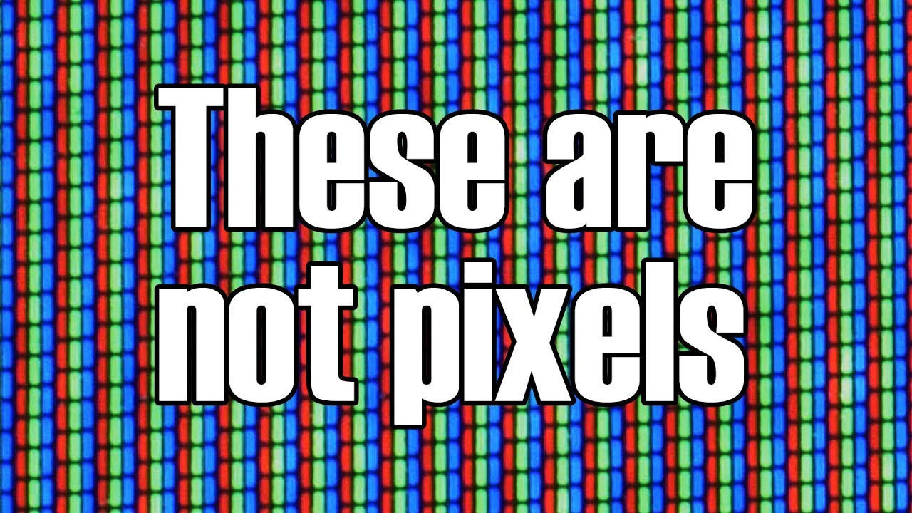
In this video we explore how we added color to everyone's favorite passive entertainment medium. Modern color broadcasting began in 1954 after years of experimentation, and this video will teach you the early history.
Technology Connections is a YouTube channel dedicated to exploring the history of technological innovation. You can support th...
i think if i were to replicate a more modern LCD display, i would have to "pixelate" the input texture
i may be totally wrong though
It's more that in you screenshot we can clearly see that some sub pixels are half illuminated, which doesn't make sense ?
https://youtu.be/dX649lnKAU0?t=680
Ok, my bad, it is possible. You learn every day 🙂

just use your oultine shader on the sprites for ui
i'm not sure how to do that
do i need to attach it to UI image?
or do you mean i should edit the shader itself?
i'm sorry, my shader knowledge is very limited, despite searching stuff on the internet
hola fellow coderz, i have a shader issue with my water plane. im using RGB to do vertex position displacement but the old format used G in RGB to connect to the input of the Combine but then i read it was swapped to B (blue) in the Y axis. when i have it in G the water plane appears but has no displacement. when i use blue the plane goes all scrunched up and flat. cant figure it out. can provide screenshots of my shadergraph if necessary
please send us the code and when you are working with positions can you please say the axis instead of colors its much clearer that way
Sure but the combine node has an output of RGB and it is not clear as to which is XYZ 🙁
I'll grab a screen in a min
((Its shadergraph))
rgb is essentially the same as xyz
Hello, I am trying to follow this tutorial for creating grass: https://youtu.be/wbEn3PqX80c
However, when I go to paint, the tool seems to be selected on my player object and does not want to paint on the terrain. Any ideas? I have tried googling and couldn't find anything

Post about the Grass Painter tool update: https://www.patreon.com/posts/61761853
Post about the Grass Compute Shader and Blending: https://www.patreon.com/posts/62240948
My Github site with all tutorials
https://minionsart.github.io/tutorials/
Discord: https://discord.com/invite/astrokat
Twitch: https://www.twitch.tv/minionsart
Twitter: https...
it's like this

Is there some form of URP Shadergraph texture to get the Exposure of the Camera? I am trying to convert an HDRP Post Process over to URP and I need an Exposure node that doesn't exist.
Hey, anyone know how to access the Volume and Slice and SDF features of a 3D texture in Shader Graph?
Is there actually a way?
Hi! I made a small water shader but when testing on my mobile phone the game is running in like 3fps when looking at water


I think I figured this out, had to change this setting:

I assume you're referring to the visualisation modes for Texture3D assets in the inspector. You'd need to look up "raymarching" or "volumetric raymarching" techniques to replicate the SDF and Volume ones. You'd need to use Custom Function nodes to achieve those in shader graph as it requires a loop.
As for the Slice one, that's probably just 3 quad meshes, sampling with swizzled uvs & slice position passed in via property.
Could try swapping the Simple Noise node out for a repeating noise texture instead.
So basically the Texture3D is the density of liquid (amount of liquid) at a given point in the container. It's a hot liquid, and I'd like to show the amount of heat imparted to the container, with some kind of heat decay (red-->orange-->yellow-->green-->dark green). You have an idea as to how to best do this, whether in Shader Graph or in C#?
@regal stag It's better now, can i do other improvements?

Trying to hook up the 4th layer now, I'm not even sure if this is how to correctly specify that keyword.....
are there any tutorials on it anywhere?

here is my shadergraph and the result im getting

anybody have this problem before? i just want the water to be displaced so it wibbly wobbles
if i switch the out to B it has displacement but its squished, if i switch it to G it will display a flat plane but no displacement. cant figure it out
You'd just need the _TERRAIN_8_LAYERS part for the reference. (Whether it'll actually do anything though idk)
hmm, odd, no dice
Which axis you want would depend on the orientation of the plane mesh data - but usually Y/G is up.
Since you're doing displacement in object space, maybe check the scale of the plane object too as that would also be taken into account. Make sure the Y scale isn't set to 0 or something.
any idea how I can add a custom float out on a shadergraph? or would I need to do a regular hlsl shader for that functionality
legend, thank you
Shaders don't typically have outputs like that. What exactly is the intention/usage behind this float value?
I have a script that flips a bool controlling which sprite sheet is playing, and I'd like to have the script know the index so the bool can only be swapped when the sprite index is currently 0
the sprite sheet is flipped as a function of time
ie if I had a getFloat("currentIndex") then it would be trivial to handle
I don't really know what part of HDRP enables that 8-layer keyword/feature. Maybe it's a setting somewhere on the Terrain component?
Ill check it out, thanks
Instead of using a bool & time in the shader, I would calculate the index in the C# script and pass the index as a float property.
Oh I've just realised you've used a enum keyword for this too. You'd likely want a boolean keyword instead.
Hi, do anyone know how can I blur a Texture in unity shader graph ?

In this post-processing shader video for Unreal and Unity, I show how to create a filter that blurs the image by taking 7 samples and blending them together. Then I show how to use that same filter to apply sharpening to the final image. Next week, we'll use everything we've learned so far to create an underwater appearance.
Here's last week's...
here you go
Thank you I will try it
@regal stag need expert advice if possible, I have a feeling this is way above my head generally
just trying to figure out how to do a heatmap (like infrared goggles) shader from a RenderTexture with said 3d properties
like so but not flat:

Why do parallax occlusion mapping looks ugly at some angles?


IDK what you RT has as informations, but maybe just take the luminance as input for a gradient sample ?
At grazing angles POM need more steps (more precision) to resolve. If it lacks them, you get this stepped effect.
with more steps it eats fps
Well, yes.
I mean, that's just how it works.
You can control the steps count depending on the view angle to have less steps when viewed vertically and more when the angle is near tangent, but this look is just normal for POM
Tried to make a shader, that would flip through a sprite sheet, but the frame was different depending on the object's position. It works fine if viewed from top down, using an orthographic camera, but otherwise it looks like this. I don't know what went wrong, and I don't know how to describe it. (also sorry if the images cause the previous conversation to get knocked out of sight...)


Can i do it on shader?
If you want the frame to be different depending on the object position, use the Object node.
Here you are using the Position node which returns the pixel position, so it is changing for every pixel.
You can still use it, but you may need to step it so that the value is constant for all the pixel that a single tile will display.
Shader or shadergraph ?
Either way, the formula is something like : steps = lerp(max, min, abs( dot(normal, viewDir) ));
shadergraph
Ok
Well, same, but with nodes 🙂
Thank you
surprisingly, the pixel position is what i want, i think, cause then it makes the animation transition smooth, and actually looks better then using the object's position. Do you think that could be what is causing it to render all weirdly?
I can not say what is weird or not in this capture, I only see noise on purple pixels ...
BUT I am 100% sure that using the pixel position to offset the tile index can result in errors if not controlled properly
ill try it with object position, and I'll get a better screenshot using some debug textures with easy to see edges, brb!
ok this should be easier to see what is weird (these should be a flat plane of these cubes using the debug texture)

A flat plane ?
But the geometry doesn't look flat ...
@amber saffron is it fine?

that is the issue, believe it or not, those cubes all have the same y level and the same scale
and sadly switching to object position did not fix it
Ah, the issue is alpha rendering order then I guess.
Looks like
potentially, as this is a ground block (nothing should be below it), should i then set it to be in the negatives for sorting priority?
If all the cubes are submeshes of the same mesh object, the faces are not sorted against each other, resulting in unpredictable overlaping of faces
Easiest would be to set the shader to be opaque if you don't plan to have transparency
I didn't even know submeshes existed before that message lol, I'm pretty sure each one is its own mesh
i plan on using this shader for a few things that will need transparency, so should i just have a transparent version, and an opaque version then?
I have a normal map that is updated when the texture is changed. How do I get that to update in the game after it changes? I can see it changing in the material as it changes but it doesn't apply to the game.
Yes
ok thanks!
How is the normal map updated ?
I'm using Normal Map Maker from the asset store. It generates the texture and then I apply it to the sprite renderer's material with set texture _NormalMap
It updates in the material but not in game. Very confusing how this works.
Hmm just discovered another oddity with my shader. It seems the further away from 0 0 0 i go, the more the scaling part of the script breaks. (it is meant to stop pixel bleeding)


Are you 100% that it doesn't work ?
IT'a hard to distinguish the normal map effect on these brown edges.
Did you try to temporary remove the color texture to see the lighting with the normal ?
this only seems to happen in the negative x direction, odd
The bottom of the water should look like this.

I have an idea. Let me test a bit more.
Sorry, I don't understand the issue here either.
I see some node that result in constant tiling and offset, and a tiled texture (with some green/yellow color change ?), that's all.
that tiled texture is this, and in that screenshot it is trying to show the first frame, i think. The further from 0 0 0 the more the texture is rendered weirdly like the screenshot.
the nodes basically allow me to scale the pixels displayed, this allows me to stop the 2nd frame from bleeding into the 1st frame
does that make sense? Sorry I'm not the best at explaining lol...
Maybe some issue with the flipbook node ... try to pu a Fraction node between the UV and flipbook
Ok, I'll try that and report back!
nope, still rendering oddly
I'll quickly try removing those scaling things, to make certain it is them, that is causing the issue
Aha, I was wrong! It is not the scaling stuff that is causing it to go weird! Fascinating!
huh, I have been bamboozled... For some reason changing one material of one object, affects how a bunch of other materials render
by having no opaque versions of the shader present in the scene, the issue of far places breaking rendering is fixed????
im so confused lol
The material asset is shared by multiple objects
yes, but what i mean, is that i have some objects with the transparent version, and some objects with the opaque version, and if i remove all the objects with the opaque, then the issue goes away
🤔
even weirder, the previous issue (the one with the cubes not rendering right, due to the transparency), gets fixed if i go back to an old shader (that is transparent), but manually lets me select the tile
Something somewhere is going wrong...
what the hell... turning shadows off in the opaque shader causes the transparent shader to display only a single pixel from the texture that is super stretched
Should I bug report this? As this doesn't seem like intended behaviour...
I have the feeling that something is wrong with your setup, but there is so many informations and unknown about what you did that it's not easy to decipher.
Unfortunate... Is there anywhere I could start, to try work out what is going wrong?
I tried converting this shader by valve to HLSL to use in URP project
https://github.com/ValveSoftware/steamvr_unity_plugin/blob/9442d7d7d447e07aa21c64746633dcb5977bdd1e/Assets/SteamVR/InteractionSystem/Core/Shaders/Silhouette.shader
I managed to resolve most of the error by referencing this blog post https://teodutra.com/unity/shaders/urp/graphics/2020/05/18/From-Built-in-to-URP/
But it seems like it is not doing anything when using it in my project.
I just don't understand why having objects with certain materials, affects other objects with different materials, it doesn't make sense....
I'm new to shader programming just read The Book of shaders and shaders cook book. I'm getting shader error in unity. I initialized the _SunTint field and tried to use it in a method. But VsCode doesnt highlight titnt variable as others. And I'm getting error. Error message is on image.

Sorry i just i didnt count variables carefully
Ok, i found a solution!!! But it makes no sense!!!!! Any scene that has been opened more than once, gets infected with the distance issue, which means by creating new scenes everything is fixed, until you close and open that scene, and it is once more broken!!
Indeed, makes no sense 🤔
Yup! I reckon that either there is a terrifying bug somewhere, or that I have mangled my setup so badly that these shaders have decided to give up! Thanks so much for all the help. Hopefully tomorrow I'll find a way of fixing this oddity.
Some of the faces of the probuilder objects are not visible only in the material with the shader I made. Can anyone tell me why it is doing this?
Some would think that the problem is from the shader you've made, but you didn't share any information about it.
🤷♂️
how do I rotate a mask around the center of the uv?
Use rotation node to rotate the UVs before the mask input, centered on 0.5,0.5
there is a rotation and offset node
I wonder, how can i read vertex color on a terrain? I want to use them in a custom shader with shadergraph vertex color node, but im confused with terrain layers.
iirc the Terrain system uses mask maps, not vertex color for the layers and details
Hey guys, I have a problem where I have a shader that takes sprites and changes their colour. The shader works great and is visible in the scene view but invisible in the game view. The only way I found to fix it is to change the canvas that has the sprites on it to camera instead of overlay but that messes up the game a lot. Anyone knows if there is a different fix?
hello guys im want to make an Texture 2d on my Rounded Rectangle but i dont know how
Add and Multiply not work

Use lerp node to stack things.
A = base
B = upper "layer"
T = B&W mask to display B over A
Please show graph ?
@amber saffron thanks again!

uv node pluged into split node, and the ping pong node is essentially a simatrical triangle wave which is then being combined
hey by using amplify, and using transparent how do i counter act the distance dithering https://cdn.discordapp.com/attachments/563719446393389076/1075437358595452960/0bef1bf537e377659801a10d0277f9a5.mp4
I can only split colors that are contained in a vector, I can't use that for XYZ


I don't understand the issue, you are doing exactly what you wanted.
The split node works for vector 2/3/4 and color, spliting into RGBA / XYZW components

What I need to look up in order to apply shader only to parts of a mesh surface?
I have a mesh constructed out of a height bitmap, and required parts can be based on the colour from the height bitmap or from a different height bitmap. Whichever is required for the implementation.
^I have a similar problem to the above. I got this amazing grass creation script tool that works in brush mode, but I want to change it so it generates the grass with the settings I implemented not with the brush but all over a specific terrain material I have
and whats the problem with that
Use a step function in the shader with the heightmap color as input to decide whether to discard a given fragment or not, or apply different treatment to it
ok I should rather explain to you what am I trying to do with this shader
I extracted a model from the game Animal Crossing on 3DS but in order to save space in the rom of the game, the developers made a texture that can be mirrored, so if I import a model from animal crossing without shader I have weird textures like this:

instead of this :

as you can see the furniture have some problem that i can fix by using this shader
(the seats are very weird)
right and I am guessing you want to recreate the shader and where is the problem when doing that?
exactly
and where is the problem when doing that?
my texture is not recognized, I simply have a red line and a green line which represents the RGB colors but I do not see my texture

Like this
show me the shader
ok i can add one thing i guess
the texture at the right in the inspector is absolutely useless

and i will remove the other node "split"
where are you using a texture? or is that the texture?
I think the uvs of the object are not proper
have you checked the uvs of the objects?
how can i get this in a shader?
what?
you are allready doing it but the uvs you are getting are probably shit
you either need to fix the uvs of the objects or use the triplanar method
triplanar?
its a technique in shaders with that you don't need uvs
Wait, I can pass fragments to another shader? Or I need to integrate step function into the target shader as a part of the rendering process?
I think he means that use the heightmap, and depending on the heightmap pixel value you use that to do different treatment depending on what that heightmap pixel value is
i.e.
float heightValue = tex2D(heightMap, uv).r;

if(heightValue > 0.5)
{
  //do A
}
else
{
  //do y
}
Hi there,
does the : VPOS semantic return the screen space position of the vertex in pixels or in normalized device coordinates?
Would appriciate help here, as I am having trouble finding the right documentation
should be screen space
let me double check
appears to be yeah

yes screenspace and sv_positon is clip space
I have a question of my own now actually
so i've written a shader to emulate the effect of a CRTV screen, and in an attempt to mitigate the moire effect, I've used one of the screenspace derivative nodes to determine when to draw / not draw the phosphor pattern
generally it works great, but it introduces some aliasing artifacts
Without distance fade:

with:

im wondering if there is a method of reducing those artifacts?
Well specifically I mentioned using step because branching is not ideal but conceptually yes this
return lerp(mask, float3(1,1,1), length(fwidth(p)));
this is all the code is, if that is helpful. p being the UV coordinates in this case
Thank you!
No problem! Happy to help
thank you
don't get it I think it looks great ¯_(ツ)_/¯
the ones in the second pic?
yeah those ones
they emerge from the fwidth() function
Can we change a shader graph's enum keyword programatically during runtime? I've tried Enable/DisableKeyword but it doesn't do it. Any help would be greatly appreciated
Nevermind, I was missing an underscore in my string reference, oops 😛

is anyone familiar with using CRTs? i keep encountering this warning with my implementation that more or less stops the coroutine from cycling through
        IEnumerator ProcessDyeTexture() {
            foreach (KeyValuePair<string, List<string>> skinPair in skins) {
                SkinDye skinDye = dyes[skinPair.Key];
                CustomRenderTextureUpdateZone[] crtZones = new CustomRenderTextureUpdateZone[skinPair.Value.Count];
                for (int i = 0; i < skinPair.Value.Count; i++) {
                    AtlasRegion region = atlas.FindRegion(skinPair.Value[i]);
                    if (region != null) {
                        CustomRenderTextureUpdateZone crtZone = new CustomRenderTextureUpdateZone();
                        crtZone.updateZoneCenter = new Vector3(region.x + region.width / 2, region.y + region.height / 2, 0);
                        crtZone.updateZoneSize = new Vector3(region.width + 1, region.height, 0);
                        crtZones[i] = crtZone;
                    }
                }
                dyeTexture.SetUpdateZones(crtZones);
                dyeMaterial.SetColor("_Red", skinDye.colors[0]);
                dyeMaterial.SetColor("_Green", skinDye.colors[1]);
                dyeMaterial.SetColor("_Blue", skinDye.colors[2]);
                dyeTexture.Update();
                yield return null;
            }
code for reference
dyeTexture in this case is the CRT, tl;dr is that it's cycling through a spritesheet texture, assigning various regions (so like 50x 75y might be a sword sprite) and running a dye shader on that zone
i ended up figuring it out, the artifacts were caused by calling the derivative function after a frac call
this is fixed without restarting unity by just saving the project? i don't fully understand what's happening here
Has anyone stumbled across a shader like the one in this video?

In this tutorial I show you how to create pixel scan logo animation in adobe after effects without using any plugins. With this method show in the video you can easily adjust the settings and if you want to use a different logo, all you have to do is replace a logo inside of logo composition and everything will automatically adjust to the new lo...
Ok after a ton of trial and error, it appears that it is mipmaps that cause this! Also odd but when I first disabled the mipmaps it gave this error, but I'm sure it is fine, cause the distance issue is fixed!
Welp it seems that solution has other issues though. As now shadergraph refuses to create new nodes, instead giving me this error:

ok and trying to connect existing nodes together causes memory leaks, how fun

Why is it that whenever i use unity, i always manage to break it in the most baffling ways possible lol?
aha, it is not mipmaps, or atleast it is mipmaps, but only for 1 scene, the other scene is still broken, haha
oh and now both scenes are broken, how wonderful
I've tried googling everything under the sun, but nothing comes up! It really seems like I'm the only one to have this problem....
oh also minimising unity and then un-minimising it sometimes fixes it, but not often
what the hell
ok, creating new materials and assigning the shader to them, causes those materials not to break, atleast for a bit
unlit shader cant use multi color?
I'm sorry CK, but I don't remember the exact nature of the problem, and there's been several posts. The reason I mention this is because others may feel the same. I mean, it's hard to track a problem across several day,s, assertions, and changes. So if you have a situation like this ^^ where you can get a "sometimes fixed" image, and one that is messed up, maybe post both examples again. One where min/un-min fixed it, and the broken one. Maybe someone will have better understanding of what is going on.
One think I know is that if you're having MIP mapping issues, you'll often get "texture crawlies" going on in the distance too as the camera moves.
really?
What? Of course it uses multiple colors. It's shading colors.
ok ill try!

Maybe try putting a color into the color output.
ok so this is what it looks like when broken

and this is what it should and sometimes does look like

the issue only ever occurs in the negative x direction when far away from 0 x
it seems that anything and everything can fix it, but only for a while
this makes troubleshooting near impossible
also shadergraph often breaks for no reason
does that help?
how do i even google that? "Shader breaks when far in the negative x direction, and everything fixes it"?
this looks like the texture is not repeating (clamped)
what does that mean?
ok think i found what ya talkin about, ill try changing them, thanks

Check your texture import settings.
Yeah, those.
But that only happens when UV's go above/below 0-1, they need to "wrap around" so you can also check UV calcs.
Depends on what your shader is doing.
Also make sure your uv values are full floats and not halfs
ok setting everything to repeat instead of clamp, has fixed all the textures with transparency, now only the opaque textures are broken
hold on ill send a screenshot of my shader, it is a simple flipbook animation thingy
You might try playing with Aniso filtering and AA settings in your setup.
here is my shader, hopefully discord compression doesn't destroy it too much

ok ill try that
So the gist is that you're selecting the flipbook page based on world position.
yes, so depending on the world position, a different frame will be shown, allows me to have a sort of waving darkness affect
what is the effective range of the worldpos in units? What's the "far distance" value that f's up?
Are you running out of significant digits in your floating point calcs?
so far the smallest I've tried is -400, but I'll go quickly check what the smallest far distance is
It was just a shot in the dark. 100's -/+ isn't that bad. If you were in the 100,000 range, I'd wonder.
Maybe re-work it (IDK what it's really doing and it's too early for me to do the math 😉 ) with a modulo or something so that the math "is different".
ok just got -62 to be a far distance, but it seems it isnt consistent, and since then i haven't gotten that little since
I'll try that
where is this FPS input come from?
also is it inconsistent in editor or during play? Time node inside editor behaves differently than when running, I think
fps, is however many frames per second i want the animation to run at (well roughly, as the adding of the position does kinda melt the math a tad)
it is consistently inconsistent unfortunately, whether I'm in editor mode or in play mode doesn't seem to matter
how to reverse alpha color guys?
ah I see... so it's a constant number.
shader is hard xd
assuming it is the same as inverse mass, then 1/alpha I would assume?
ye
actually no, it wouldn't be the same, sorry
atleast i dont think so
Or try the one-minus method to "reverse it".
AKA 1-alpha
i used one minus to reverse transparent spaces so...
seems like one of the uv members might be clamped to 0, either x, or y
my wild guess is that that the modulus node give negative number (?cmiiw), so maybe add an abs node or remap node between the modulus and the flipbook node
iirc, flipbook node expect 0..1 input
modulus shouldn't be able to give a negative number
if you have python, open it quickly, and use % as the modulus operator
anything%2 should be either 0 or 1
in general x%y == somewhere inbetween 0 and y
you can also have floats, that is fine
how about -1.5 % 1 ?
I know it should be 0.5 but I'm not sure with modulus node in shadergraph
damn it alpha is on top emission
it should be 0.5, unless the modulus node works differently to regular modulus... I really hope that the modulus node works like regular modulus...
there will always be atleast 2 frames though
https://docs.unity3d.com/Packages/com.unity.shadergraph@6.9/manual/Modulo-Node.html seems to suggest it uses fmod, whatever that is
https://www.skytowner.com/explore/difference_between_the_methods_mod_and_fmod_in_numpy seems fmod does handle negative numbers differently to mod. I'll try to put some nodes around to force it to be positive then
What differentiates mod(~) from Numpy's fmod(~) is confusingly not whether or not one is for floating numbers; they are both capable of parsing floating numbers. The defining difference is how they handle negative numbers.

welp, so should i use nodes to force it to be positive? Or is there some way to get access to regular mod?
but flipbook shader can handle negative numbers
atleast it should...
if you manually type a tile index into flipbook then it handles negative numbers fine
something strange is afoot
Could recreate the mod function. If you don't want fmod, then try x - y * floor(x/y)) (equivalent to glsl's mod function)
https://www.cyanilux.com/faq/#glsl-mod
I'll try that in the morning, I don't really see why handling negatives like fmod would affect things, but at this point I'm willing to try anything lol
Hey guys, i downloaded this shader online that hides 2D sprites based off the amount of light incident to it. as you can see in the image, it does its job, but is there a way for me to make this completely transparent? it gets more transparent as it gets darker, and is completely transparent when its black, but that kind of defeats the purpose of the shader. anyone know how i can make it go transparent at this level?
https://cdn.discordapp.com/attachments/497874081329184799/1074731728557592697/image.png
https://forum.unity.com/threads/script-for-generating-shadowcaster2ds-for-tilemaps.906767/
this is the shader i downloaded, if it helps 😄


Unity Forum
Hi everybody,
Since I did not find any built-in functionality to make shadow casters fit in the shape of the tilemaps (something that I think it is...

Stack Overflow
I want to recreate the field of view effect in the game Among Us in Unity by using the Universal Pipeline and 2D Lighting system.
But when I use 2D light and Shadow, I still see the character in the
sorry i mean here


how can i fix the lines on the nose of this character?

(everything in red are the lines that i want to remove)
i could be wrong but try disabling mip maps on the texture?
you can do that in with a toggle in the texture import settings
or you can access lower mip levels with the tex2dlod() function
eg.) tex2dlod(_MainTex, float4(uv, 0, 0));
i think it could also be caused by texture filtering
try switching it to point maybe?
already the case
well damn
I removed the anti aliasing and it works
(not a big problem because i want to make a game with PS1 graphics)
anyone know a fix?
I have a geometry shader to generate billboards on each vertex of a mesh, and it works fine, except the quads seem to shrink pretty significantly when the camera is direcly overhead.

float3 center = p[0].pos.xyz;

                float3 up = float3(0, 1, 0);
                float3 look = _WorldSpaceCameraPos - center;

                look = normalize(look);

                float3 right = cross(up, look);
                up = cross(look, right);

                float3 r = right * _Scale * 0.5;
                float3 u = up * _Scale * 0.5;

                float4 v1 = float4(center + r - u, 1.0f);
                float4 v2 = float4(center + r + u, 1.0f);
                float4 v3 = float4(center - r - u, 1.0f);
                float4 v4 = float4(center - r + u, 1.0f);
i created water shader and it has side effect on objects which im looking on from same side of water. Any advice how can i solve it?

trying to create a sky using shaders and there's this weird line that wraps around the scene- any ideas?

if I turn the camera around you can see it on the other side too

Try this out
.
Probably being dumb, but I cant find that setting in the inspector for this material

Oh I thought you were sampling a skybox texture
I don't think that will apply then
No I am creating a sky with a shader
anyone know a fix for this??
Nothing can fix the deep creases in Tom Nook's face, carved there by decades of observing frivolous players coming in and out of his store, failing to pay their debts. The jaded nature of his character is etched into his very soul, into which his face is merely a looking glass.
Hi can smeone help me understand why we divide by scrPos.xy by W
float2 wcoord = (i.scrPos.xy/i.scrPos.w);
Is it to get normalized device coordinates? Or too fix the perscpetive, from my understanding the perspective was already fixed when converted into clip space?
Appriciate your help!
Thank you
Yes, it's used to convert from "clip space" to "normalised device coordinates", as well as actually apply the perspective projection. It's known as the "perspective divide", so may be able to look that up for more info.
Hard to tell why this is occurring without seeing the shader. But note that for a skybox, the UV coordinates are actually 3D (they are the same as the vertex positions). That may be related to why this is happening.
Thank you!
Hello, need help understanding why the Shader render queue keeps going back to its default value, I set it to 3010 but it will go back to 3000. Appreciate any help
The common way to fix this is sample the depth texture (Scene Depth node in shader graph) in Eye space, using the distorted screen position, then compare it against the depth of the water plane (e.g. W of raw Screen Position). Can use a Comparison (Less or Greater) into a Branch node if using shader graph.
If the scene depth is smaller, the object is above the water, so if we distort the opaque texture (Scene Color) it'll result in this side effect you see. There's no way to really know what the pixel colour should be behind the object - but it's common to just use the non-distorted Screen Position. Won't be perfect, but should look better than the current result.
And if the scene depth is larger, then can continue using the distorted screen position. These would be the True/False inputs of the Branch.
Here's a simplified example (from https://www.cyanilux.com/tutorials/water-shader-breakdown/)

How are you setting the render queue?
From the inspector
Hmm I'm not sure then, maybe a script is overriding it?
does anyone know how to get the default nodes back into these? if i try to add them i just doesnt even show up
supposed to look like this yknow

Have you got a Target selected under the Graph Settings (tab of Graph Inspector window)?
Oh, thank you very much!


i feel like this is pretty simple to fix, but i dont know much about shaders. can anayone please help me with this its been hours now
Could someone help me understand how this makes repeating bars across the screen i am having trouble figuring out this piece of code. Thank you
`fixed4 frag(vertOut i) : SV_Target {
float2 wcoord = (i.scrPos.xy/i.scrPos.w);
fixed4 color;
            if (fmod(20.0*wcoord.x,2.0)<1.0) {
                color = fixed4(wcoord.xy,0.0,1.0);
            } else {
                color = fixed4(0.3,0.3,0.3,1.0);
            }
            return color;
        }`
wcoord is a position on the screen here, (0,0) in bottom left and (1,1) in top right.
20.0*wcoord.x is taking the X/horizontal axis, and changing it to range from 0 to 20
fmod(x,y) is a hlsl function which returns the floating-point remainder of x/y. It looks like a sawtooth wave (/|/|/|/) when graphed, but ranging from 0 to y, so 0 to 2 in this case (but repeating, 10 times, I think).
Since that ranges from 0 to 2, comparing it to < 1 means each half gets a different colour.
I think frac(10*wcoord.x) < 0.5 would also be equivalent.
Thank you!
here is my sky shader- worth noting I was trying to follow this tutorial: https://medium.com/@jannik_boysen/procedural-skybox-shader-137f6b0cb77c

It looks like your using a Lit graph so that might affect things. Should probably use an Unlit one. (can change it in Graph Settings)
Can't see anything else that would cause this, unless there's a mistake in the Skybox UV, maybe double check it against the tutorial.
Does anyone here who has a singular clue as to what a shader is/does/works can help somebody that knows absolutely nothing T o T ! I am currently running into a problem with my first ever unity project and im a little clueless to say the least, and now I am stuck on some shader/lighting issues! Any help will be appreciated :))
shaders at there most basic are all about putting a color on the screen
there we go, job done 😛
thank you for sharing your wisdom wise one 😌
but on a little more elaborate note shaders are GPU programs, that are solely responsible for shading all the objects that are in your scene
Would there be any reason a specific would cause an object to light up entirely, even if only part of a light is touching it?
yes, but the problem with that question is that it could be due to a multitude of things
NooOoO T _ T
I would ask first what kind of lighting you are using, and what render pipeline
I'm not using URP or HDRP so the standard pipeline I assume, and the lights are also standard unity pointlights :/
the shader in question is using some form of vertex lighting if that helps at all 😭
*spot lights not point 😰
well right off the top of my head
sounds like the issue you might be running into is about per pixel light limit
by default its at 4 usually for built in pipeline but you can increase that number
interesting 😌

I gave it a quick try but it didn't seem to resolve the issue unfortunately :/ I greatly appreciate the help though 😄 ! I am sure I'll inevitably get too the bottom of this >:)
Take a screenshot of the material

Ah, well vertex lit shader would be lit by the vertices. If you want pixel lights working, you'll need to use a different shader.
If you have the time, would you try dumbing down the difference between the two :))
You'd need to look into the shader code for details, but basically vertex lit shaders apply light in the vertex shade(per mesh vertex that is). Shaders like Standard shader, apply light per pixel drawn on the screen making them quite a bit heavier than vertex lit shaders.
I think that makes sense 😄 thank you for explaining it to me 😌 I've learned something today
That being said, vertex lit shaders still shouldn't be "lit as a whole" it's supposed to be less precise.
So maybe take a screenshot of how it looks like.
Is anyone here firm with a shadergraph of water ripples affected by an object? I am currently testing around and can not find the best way of approaching this. Should I feed a texture that is updating the points where ripples are or is there some kind of array I can feed into shadergraph to examine positions I can create ripples from. Any insights and ideas are very welcome, thank you 🙂
I don't think it should be handled by shader(not entirely at least)
what I can think of is using a look up texture, usually a render texture, for the water mesh vertex displacement. then you blit a wave pattern in the object position into the render texture which largen and fades overtime.
I mean you can posterize and distance to generate ripple basics, but of course only for one object right now. I could just copy it 4 times, but what if I wanted a dynamic array to be used to have multiple ripples. But about your idea, do you have anything I can look into to combine that idea with a pattern of multiple "impact points"?
Like this is already generating an animated wave I could control. But its just one

using render texture, you can have a lot of impact point with minimum impact
Hm, gotta look into this I guess. trying to understand how to use the rendertexture and add impact points to it, thanks for pointing it out 🙂
This is what it currently does, basically having the effect I want (ignore resolution and blockiness)

is there a smart way to "lerp" in shadergraph from like a stored position to the new one?
How can I control the position of the lighter-coloured rectangle projected on the larger one?

Hello,
I am working on a 2d platform type game,
I wanted to make the texture for the platform look uneven,
No change in colliders needed only the look i want to change to uneven like a uneven rock type thing.
How can i do this. If it is possible
Adjust the UV coordinates going into the Rectangle node.
Either use UV node and Add some Vector2 offset, or can use a Tiling And Offset node and connect to the Offset port for same effect.
Thanks a lot!😃
Is this a typo in the documentation for Stencil Buffers, or am I missing something? https://docs.unity3d.com/2023.1/Documentation/Manual/SL-Stencil.html


It should be "zFailOperationBack and zFailOperationFront", right?
Yes
can someone help me with this pelase?
I have a noise node and I want it to act like alpha (so I want the black regions to be transparent and the white regions to be white (and then I'll eventually multiply this by a color)). How can I do that?
My guess is that you have some global light that is adding a little bit of light to objects in shadow, so they don't become fully transparent. What method are you using to add that bit of light to the shadows?
Hi, I'm trying to create a Shader for this Planet so that there are different textures on different parts of it. Right now i'm controlling it through Noise but I'd like to texture it based of the height of the terrain so I can have snowy mountain peaks. How could I do that?


You just need to connect the noise output to the alpha input.
Here is the thing: I want the output to be blue where the noise is white and red where the noise is black

use a gradient with a sample gradient node
Well, you'll need to calculate a height value. If you have some heightmap texture, you could sample it in this shader. Otherwise, you will have to calculate the distance of each vertex from the center of the planet and then define some min/max range using Remap to convert that to a 0-1 scale.
If the pivot point of the mesh is in the center, then to calculate the distance, you can just use the Length of the Object Position.
The value you get could be in any range, depending on the size of the mesh (unrelated to the size of the renderer/game object). Maybe you're lucky and it's already between 0-1. But most likely, you will need to Remap it.
yeah, that it ussually doesent work first try so i'm expecting that
For some reason I can't show that gradient from above as a property in the editor
The Expose checkbox is greyed out
That's somewhat intentional. Gradient objects in shader graph can't be exposed
For this I'd use two colour nodes/properties, put your noise into the T of a Lerp node, and the colours in A and B
Ok, I'll try that
this is the only light source in my level, im pretty certain

i have the shadow strength not fully 1
It worked. Thank you!
Try setting shadow strength to 1, but then use a global light to light up the shadows.
thats done it, but now everything is super bright

do i just do like 0.5 and 0.5?
or just different target layers
Very cool effect but I think I'm doing something wrong here

Hey everyone, I am trying to use my vertex displacement to also get some refractino going in shader graph. Anyone got a good way of recalculating the normals from that displacement?
I have a geometry shader that's used to render grass on a mesh
would there be a reason for it not showing up in the scene view?
and now its not visible in either game or scene view
Hello guys I copy shader graph code to shader but its give me error and i cant avoid it , what can i do??

its a warning not an error and it also tells you how to get rid of it
I've got a few methods listed here : https://www.cyanilux.com/tutorials/vertex-displacement/#recalculating-normals
A post explaining how to move vertices in Shader Graph, providing examples such as swaying grass and animated fish and butterflies. Also includes info about recalculating normal vectors.
I would not use geometry shaders for grass there are way more performant methods
Yes, you'll have to decrease the brightness of the spot light, since it's being combined with the global light. Also, it looks like the global light is too bright. The shadow brightness doesn't match before.
sorry warning then, but im not tha good yet so i dont know how to get ride of it in graph shader
You're missing the Length node.
its not rendering anyway
before you plug it into the pow node plug the value into an absolute node
cool still I can recommend to render grass differently but if you insist on using geometry nodes
you will need to give us more info
can i only light specific gameobjects? like can i keep the player under a constant light with one light, and calcuate the shadows and stuff with another light?
what info, I need to render grass, that sways, and that I can change the color of
I would watch a very good gdc talk from the developers of the game ghost of tsushima they have got a very performant solution for grass
im not actually using literally power node or absolute

Thank you so mucht! I got it working and it looks great
are you sure the error is refering to this shader, but tbh is something not working cause if everything is working as expected it probably doesn't matter
Hey can someone help me understand as to why TEXCOORD0 is described as 'first texture coordinate input' Does it provide the UV Coordinates for a specific vertex / can a vertex have multiple uv maps?
`float2 uv : TEXCOORD0 // first texture coordinate input`
Thank you!
You can do it two ways, either write the height data to vertex color information of the mesh or you can get distance by subtracting position from the object origin position in shader graph
ive got this planet in unity 2D and I want an atmosphere around it and it seems that shaders would probably be the best way for it
I can create a mesh in the right shape but i cant figure out how to get it working
the second image is a sort of attempt at getting it working but it just doesnt seem to do what id expect with 2D meshes without sprites or anything


What kind of UVs does the mesh have?
Could plug UV node into color to see what we're working with
yes will give that a go
its possible that im generating the UVs wrong


ah seems theyre all (1,1)?
its got vertex colours also but can just ignore them
the final thing wont have them just while im checking out shaders
That seems likely
uh hm i evidently did not expect to have to use them in the future
nice
i guess the next issue is how on earth do i generate the UVs for an arbitrary polygon - would the edges need to be along the sort of (1,0), (0,1) edges of the UV, or would i just be able to divide vertex position by bounds?
not really a shader question at that point i suppose
Anyway I can draw clouds using shaders in the built in pipeline? this is my first unity project and every tutorial seems to use another pipeline and Im afraid if I change pipelines it will screw up what I already have
what kind of clouds?
Not to be a weeb on main but I really like the clouds in Genshin Impact
nothing wrong with being a weeb 😛
but just to preface real quick technically you can do whatever on the built in pipeline, the difference with the other render pipelines is most of those features/effects are built in.
I'm not to familiar with genshin impact but looking at images, the sky looks to be heavily artist driven
most likley just simply hand drawn clouds that are overlayed on a skydome mesh that rotates/animates based on weather conditions/time of day etc
ahhhhhh sweet
hrm. do I want to draw clouds? was kind of hoping to mess around with shaders more
well there are many ways you can achieve it, I'm not familiar with the game and seen it fully in action but you could certainly achieve it in many different ways
the simplest and fastest way I could think of is having artist textures, but you could achieve it with shaders and procedual textures

Today we are going to see how to create a simple Clouds shader with Unity Shader Graph!
Enjoy!
Wishlist our indie game :D https://store.steampowered.com/app/1763860/Rabbits_Tale
00:00 Intro
00:38 Scene Overview
02:23 Cloud Shader
09:50 Vertex Offset
14:35 Alpha Clip
15:15 End Result
CLOUDS PROJECT: https://www.ga...
not quite the same as the style of genshin of course, but its a starting point
thanks !!
you can also make volumetric clouds but these are more technically challanging
How is it possible to import a model with the custom shader too?(Use Nodes enabled and from Blender)
Shaders are not compatible across engines
But many can be baked to texture maps or recreated in Unity
Any package that adds support for Blender Shaders?
No
dam, thx
Hey guys, is there anybody familiar with shader graph and can help me with some 'simple' shader which turns out not that simple
The idea is to make a shader that will display a border around the mesh. It should be tilled with object scale.. I managed to did it, but it totally breaks when it comes to custom shape

These are same shader but one is just a rectangle and another is some complex polygon. I'm stuck for 2 days xD [*]
its hard to figure out when not knowing about the code

Outlines are, unfortunately, hard. You either have to build it into your mesh (e.g. encoding it with vertex colour) or go through one of a set of fairly complicated procedures to get the outline.
I thought the 'inner' outline would be easier to achieve 😔 at this point I might consider if it's possible to split the mesh i want to work on into two parts
we can't help you like this
well its literally not showing up
I tried switching all my render settings, changing around stuff in the shader
inside this project geometry shaders are broken
if I open a new project they're fine
whats not showing up
Hmm I can imagine what a shader looks like when it's not showing up
oh its just not showing up
just gimme a second to show you what I mean


same models, shaders, textures, unity version, urp version
only difference is the project
Looks like I imagined it
I've tried matching project settings, and that also doesn't work
any pointers?
should I just move my assets into a new project
how can i make a trail renderer pixelated with a shader?
Try comparing the two in the frame debugger. Or check into RenderDoc.
I wish I was kidding when I say that it magically fixed it self
at least its fixed...
anyone knows how i can find in shader's code a function that makes it slowly dissapear pixel by pixel (possibly not literally)
when camera is at a certain distance, or the model is at certain screen height?
this shader is rather big and undocumented so its a bit hard
the reason is, theres a Billboard on last LOD, and it slowly fades to invisibility on a LOD before that
looks super poorly
Might be some kind of distance based dither.
So I'd look for dithering functions...like looking up into a table or a texture based on distance and/or screen space location, and then doing either a discard or setting alpha to zero based on the results.
someone dm'd me about this but i declined accidentally, if whoever that was messages again ill answer sorry
Is the foliage here texture based? Under the texture's settings there should be a "mipmaps preserve alpha" which might help with this
assuming i got UVs on all the points what can i do next? the UVs are just gotten by diving the vertices by the bounds so (0,0) and (1,1) are not necessarily on the shape
ive just got this applied on the ground itself but the hope was to use it as an atmosphere shader so id just apply it to another shape thats a bit bigge and behind this main one

another complication is that im using pixel perfect camera so idk if i have the option of using a render texture and applying a shader to that instead
Ideally the UVs (or at least one axis of them) would follow the shape, then you could just use that gradient as the falloff/alpha for the atmosphere.
yeah exactly, just doesnt seem trivial to do that
im toying with the idea of passing in data into the shader through the normals
i suppose UVs work too
do UVs / nomals normalise the vectors they receive?
data seems to be going missing its not doing what id expect


You're using shader graph right? That would be normalising normal vectors automatically. But UVs wouldn't be
ok ok so UVs are the way to go sure
Guys would it be possible to make a tape measure shader that I can just stretch a small rectangular prism and it extends with the markings on it but also has numbers counting up(this is the part I’m unsure about)
Context: I’m making a VR game and want to add a tape measure that you can pull out
do you have a suggestion how to find the distance to the edge of the polygon from inside the polygon? the built in ClosestPoint only works for points outside
Hmm well, Should be able to get the scale of the object through the model matrix. In shader graph it would be from the Object node. In hlsl should be able to use something like
float scale = length(float3(UNITY_MATRIX_M[0].x, UNITY_MATRIX_M[1].x, UNITY_MATRIX_M[2].x));
Though unsure if you want x, y or z axis as that depends how the object is orientated.
Could use that to scale your uvs (or object space fragment pos). Should be able to get lines/markings by doing something like step(frac(uv.x * scale), 0.05);
Getting it to actually display numbers would be a bit harder though. Maybe instead of doing it procedurally it would be easier to use a long texture. Can still sample it with scaled uv coords. Not sure what it would be off the top of my head though (float2(uv.x / scale, uv.y)?).
No idea sorry, probably better asked in a coding channel
ty anyway tho
think the plan is just loop over all the outside vertices and find the lowest distance from point to each edge
Bro thanks for that in depth response, I’ll have to give it a shot when I get home, had to go get some food
Hi I might be off, but is this blue overlay over tilemaps usually done with shaders?

yo ty for your help my guy

ofc doesnt look how it will but the datas there
Yeah 😄
I mean, everything being rendered is using a shader. But I'd assume these are meshes or quads with a texture.
ive got this so far, how would I make the marks thinner?

Adjust the In port on the Step node


this would work if I could make them closer (meant to reply to the other one)

Oh right, you'd want a Multiply before the Fraction node
bro is a math wizard 💀
how could I make the bottom and the sides not have the marks?

Could use the Normal Vector node (object space). For the top face it'll be pointing upwards (0,1,0) so Split take G output, Comparison (Greater) with a value of 0, into a Branch
Current graph result in True, Color node for sides/bottom in False
bet
also is there an equivalent to this node from blender in shader graph?

found it
sample gradient
Kinda depends what you intend to do with it. There's a Gradient & Sample Gradient node, though they can't be exposed to the material - only hardcoded.
For just two colours, can use lerp. e.g. https://www.cyanilux.com/tutorials/color-swap/#lerp
im going to use it to make the lines not go all the way across it

I just need to make it yellow now
I dont know what im doing 
So remapping values, in that case I'd use Step (hard cutoff), or Smoothstep, or Inverse Lerp then Saturate. They'd be cheaper than the Sample Gradient.
hey I did it

using step
I dont know how in the world I would ever put numbers on it though
so idk if I am
I might just leave it like that 
https://gyazo.com/4f2e2cefe604b4b96ad1d68124a5ff1c.mp4 when you pull it out it just extends, how could I make it look like its coming from the tape measure?
Could use some kind of number texture sheet
With digits from just 0 to 9
And using vertex positon and some fancy procedural math
that sounds extremely complicated
@gusty canyon if youre just rescaling, then you can offset based on scale. If youre going to be wrapping this thing around stuff dynamically, and it wont keep a straight line, you probably will need to remap the uvs
What your making seems complicated, its all procedural so dont really see a better way
But a number sheet I'm sure would be the route to go
Are you using mesh UVs or vertex position for the markers?
this is the entire shader rn

trying to get the offset to work
I dont think im going to add numbers
Maybe if you subtract 0.5 from the position R, multiply by scale, then add 0.5 again, that might do what you want?
Or maybe 1 rather than 0.5, I'm not sure what the scale of the mesh here is
and plug it in here?

https://gyazo.com/bc0c591192f6c0b8322332faf3775bc2.mp4 didnt quite work out
Nah, you're multiplying by the scale twice now. Put it into the multiply by 30
its working but its coming out too fast
do I really gotta play with this value until its perfect 💀
0.09217 is pretty good
idk what that number represents
now I gotta actually make it pulloutable
thanks guys 
yoo kinda snazi ty again for the help
that looks really cool
i like the vibe youre going for too my guy
thanks 
Does Unity support texture array compression?
i think they added that in some later version but i don't see it
<@&502884371011731486> @grand jolt
!ban 856146380052627497 spam
 king egg. (Skiku)#6265 was banned
Question because I can't find it anywhere on google but what are the best practices for making say a low end version of a shader in shadergraph?
Say I have some triplanar mapping stuff going on, could I have a branch that checks if a certain global is true or false to do that triplanar mapping or not and would it save performance by not doing that or does it still have the overhead somehow?
there isn't too many resources out there for it sadly because the kind of shaders that say a project would need can vary so vastly
but the general guidelines that are said do apply
if you want a low end well performing shader, generally the less computations that you do, the better
So branching to skip doing triplanar mapping should work?
hmm I would try to avoid branching honestly and look into shader variants with macros
but your using shadergraph which I don't think supports that...
i might be wrong, not familiar with shader graph, but generally advice for having well performing shaders. Keep the computations as simple as possible
less is better
which is why unlit shaders perform well on mobile, all its doing to shade an object is sample a single color or texture and that is it. you can add additional steps like ok I will sample realtime diffuse lighting. That is an extra step. Ok I will now sample another texture map for normal mapping, that is another step, etc.
You can set up a Boolean Keyword (or Enum Keyword) in shader graph blackboard (then drag it into the graph and connect On/Off ports) to create variants. Some info here : https://www.cyanilux.com/tutorials/intro-to-shader-graph/#keywords
Oh cool thanks
Thanks guys
Hello guys got a bit problem in blender i made tree with UV and Bake textures everything looks good there but when i import to the unity and set all up my textures all are stretched .... they cant find the right place why is this happening?


Hey im new to unity so im new to shaders (shader graph) to be honest i watched some videos about making something with shader-graph but there are no explainations why to use the nodes is there any video that shows all the nodes and their functions?
Trying to use a material with a custom shader. My project uses URP and has the renderer set in the quality tab in the project settings. I also cant convert the material to an URP material cause it says theres no converter

Anyone knows whats causing this/ what might we the solution
Branching will work, particularly if it is branched based on a Uniform (aka constant passed in for all drawing), but I'd check the generated code from shader graph. And like Cyan said, the best way is a shader variant.
That said, triplanar isn't all that bad, GPU wise. You could just try it without any branching options, benchmark it on your lowest target vs doing the other thing, whatever it is.
You'll have to rewrite the shader by hand, to be URP compatible.
Cyan has some resources on his site that may help you.
Explains how shader code (ShaderLab & HLSL) is written to support the Universal RP
Or duplicate the functionality in shader graph.
why does my skybox change the color of everything to a bit of a tint? the original didn't do anything

i dont have any post processing enabled either
did you change the color of the directional light?
nope
its the same as it was
if you wanna test it there it is @frigid yarrow
like i didnt change anything I just applied it
yeah for some reason changing the skybox effects lighting
not just a thing with this skybox
Under the lighting tab, change the Environment lighting source
change it from skybox to color
so you can change it to any color you want
aight thank you. Do you know what the color is for the original skybox like the one you see when you make a new scene
i know there's a way to shade an object to always be rendered on top of other objects regardless of being occluded - is there a way to do the reverse? IE put a shader on an object so it's always occluded by objects on a certain layer, regardless if those objects are behind it?
its a light blue
Something like this i would guess

but ill fiddle with it thanks for the help
also 1 more question regarding shaders
is it possible to make a camera filter/shader that makes it look water?
I havent done that yet so idk
the cheap and easy way would probably be to simple put a filter over the canvas
Posting this again because i can't seem to find a solution on my own:
I'm writing a pointcloud shader using geometry shaders, essentially the goal is to create a billboard quad on each vertex of a mesh and then apply a point texture to each quad.
I'm almost there, the last problem that I am encountering is with the billboard math (?)
The quads seem to shrink pretty significantly whenever the camera is directly above them, which is not ideal


i'm absolutely hopeless with math, so most of the math was sourced from a github example that I found. that makes it really hard for me to diagnose the problem though haha
if anyone has any input i'd be more than happy to hear it!
OK, so it's particles, on quads, and you want a billboard shader that always faces the camera. Yes?
essentially yes
Google "unity billboard shader" and dig in. There's a few methods.
Mostly applied in the vertex shader. But I suppose you can pre-gen them in the geometry stage too.
Also, I think the BiRP has a billboard shader for particles (probably shuriken), that you could check the source for.
ill do a bit more googling then i suppose!
Unity Forum
Hi
I found this vert function to simulate billboard facing to camera . It works fine in editor and pc but in Android build doesn't works and...
https://forum.unity.com/threads/billboard-geometry-shader.169415/
Just some candidates, I ran across just now.
I've done it before, but I don't have my library organized very well to just post the code for ya.
Unity Forum
If anyone wants a simple geometry shader that will create billboards at the vertices, then this is for you.
[ATTACH]
Having some issues with a scriptable render pipeline
currently using the PSX render pipeline and i have a VHS Pro post process effect that i applied to the camera, but it doesn't seem to show
when i switch the render pipeline to none, it shows up
is there any way to get the effect to show with the scriptable render pipeline i have?
The project is a 3D built in render pipeline project
It sounds like you are using the wrong post processing
I'm confused what you mean by saying the project is built-in, but you're using a render pipeline
oh i selected the 3D startup project
that's the built in render pipeline right? not URP or HDRP
That's irrelevant now you're using a RP
oh yeah, this one, the PSX render pipeline

you're using a custom render pipeline if you've overidden the graphics setting for render pipeline, no longer built-in

I am not familiar with this custom render pipeline's post processing, it might be on automatically
the point is to use volumes and not PPV2
i added the volume thing to the camera, but I only get one group of volume overrides, the one that came with the pipeline

you will only be able to use effects that are compatible with render pipelines, presumably the one that this custom RP is based on
custom render pipelines are not the most accessible things
hmmm, i see, and there's no way to add other shaders? like the vhs one i got?
not without writing a whole bunch of custom code, no
dang
question - i know there's a way to shade an object to always be rendered on top of other objects regardless of being occluded - is there a way to do the reverse? IE put a shader on an object so it's always occluded by objects on a certain layer, regardless if those objects are behind it?
So Im having this issue where the cel shader only uses the directional light
Pastebin
Pastebin.com is the number one paste tool since 2002. Pastebin is a website where you can store text online for a set period of time.
How do I make it so that it can use multiple lights?
I can't find a cel shader anywhere that does this
Anyone know how to make a cel shader use multiple lights?
I've been struggling all day trying to figure this out
of course it does that you are using _WorldSpaceLightPos0 you will need to put in some more work to make it work with multiple light sources
I can recommend watching the videos from freya holmier, she covers handling multiple lights somewhere
any advice how to fix problem in water shader when looking through water plane that transparent object doesn't rendering?
is there any way to make a noise in shader graph pixelated?
You can pixelate anything with an UV input using this math

How can I get a depth texture from a camera to put into a graph shader?
specifically from a render texture
I am using this XOffset variable to control the X UV offset

I'm trying to make it different for each instance, but they all have the same offset. Am I missing something?

The scriptmachine is attached to the object containing the material

While the property is selected, check it's "Reference" field under the Node Settings (tab of Graph Inspector window). It'll likely be _XOffset, which is the actual name of the property in code.
I just found out ! that's the problem indeed, thank you
Hmm changing the value changes it for All active objects having that material
Oh my test reference is incorrect probably
That may be because you're setting the material asset, not the renderer.material, but I'm not that familiar with visual scripting
I suppose you could push it back into the far plane of the camera AFTER you calc the screen space (well, clip space) position in the vertex stage. But you're going to have to understand all that math to pull it off.
If anyone ever asks in the future: this is the solution

I have this fire material. If I scale my gameobject very wide , it just scales with the game object, but I'd like it to repeat itself. How would I do that?

It's a particle system witha material
materil looks like this

Another way, besides doing tricks in the vert stage of the mesh, is to render using stacked cameras.
So you could stack cameras, NOT write to depth, and render the skybox, followed by your forced-background object, into a render texture. That would put a "background" onto your render texture including the skybox and the forced-back object. You'd then render with another camera over top of that background.
This is inefficient, since you'd be overwriting pixels from the skybox later, that you'd normally not have to draw at all.
So the first camera would output to a render texture, draw the entire skybox, and then you'd draw your special object into it. These would set the depth to whatever skybox depth is normally set to, or not even set depth.
The 2nd camera would NOT clear, and would draw the rest of your scene on top of that.
If you scale up a mesh, its UVs will scale up with it along with textures you render with those coordinates
You'd have to project the texture in world or object space
Anyone have any experience with custom srps / rendergraph?
Trying to port a custom srp to rendergraph, and while I have it rendering, I'm having a strange issue with shaders drawn via DOTS/Entity Graphics specific batching not having any problems, but shaders drawn by the SRP Batcher outside DOTS in the same pass have what appears to be a corrupted read from its material properties on half the frames or so,
Not finding a lot of resources/docs on rendergraph, and dissecting the URP/HRP code has been somewhat helpful, but this issues kinda cropped up from nowhere, and I'm having trouble pinpointing why its happening. If anyone has any insight, I would be very appreciative of some direction
Unity Forum
I'm a bit lost in the specifics of DirectX and OpenGL projection matrices and how Unity (5.6.3) handles them. I'm trying to project some skybox...
It's experimental, and it's also part of the lesser-used HDRP.
Once you go HDRP, and get into things like experimental RG, you're going to have to dig in I guess.
Sorry I can't help you. I assume you've seen this already, but just in case: https://docs.unity3d.com/Packages/com.unity.render-pipelines.core@16.0/manual/render-graph-writing-a-render-pipeline.html
I have seen that bit, but its good to know thats about it for documentation, found a few example projects that have helped as well, wonder if its actually a bug vs just me doing something wrong
Yeah, IDK.
The only thing I can (guessing) suggest is a debugger to check the values coming in.
There's the frame debugger, RenderDoc, PIX, but really to fully check it I'd install vendor specific tools for your graphics card and run a debug test. You can capture frames, and mess with values, trace through shader code, etc. Very vendor specific, so see their docs.
Visual Studio has some tools too. But if you REALLY NEED to dig in, the vendor tools are the way to go.
I'm trying to get a vignette effect on my shader graph but I can't find any tutorials about it
Good idea to use vendor shader debuggers, will give that a shot next, a big annoyance is the frame debugger shows the correct vector value being set with the right value for the material even when it’s flipping out in game view
Fixed it, was 100% my fault, missed '!' negating a #if !defined(LIGHTMAPS_ON) in my shader so it was sampling random gpu memory garbage where the lightprobes should have been,
is there a way to manually add lighting to a geometry shader
since I can't add both #pragma require geometry and #pragma require surface in the same pass
Like a screen space one?
I got a sniper scope shader, trying to add vignette around the glass
You should be able to add simple directional lighting (not shadowing) with the built-in shader vars and a normal/worldspace coord in the fragment shader
I will send the shader graph later on, I'm afk now
👍 worked great, used LightingSpecular()
Funnily enough, I actually haven't really used shadergraph, however for a simple one I was going to suggest just use the distance from the uv maps center point as a progress to lerp from alpha to opaque target color, add in an offset distance if you want it to start sooner/later,
I have no idea on how to program shaders
Gotcha, not quite sure how to translate this into shadergraph, but that is the math concept you would want to use for a simple adjustable one, but depending on the platform it may be cheaper to just have a alpha faded texture that does it instead,
Hey, this might be a loaded question but I figure I'll try... I'm trying to use Tilemaps with 3D lights (built-in & deferred). I'm using the Standard shader, which works - except the Color field on the Tilemap component doesn't work. Is there an easy fix for this or a resource anyone could point me to? Anything would be appreciated, thanks!
what's the best way of applying multiple lights to the same pixel?
I tried doing this c for(int j = 0; j < 15; j++) { const half4 newColor = _AdditionalLightsColor[j]; if(distance(newColor, black) == 0) { break; } const half3 lightDirection = normalize(_AdditionalLightsPosition[j] - vertexInput.positionWS); const half3 viewDirection = normalize(_WorldSpaceCameraPos - vertexInput.positionWS); color = half4(LightingSpecular( newColor, lightDirection, v.normal, viewDirection, color, 0), 0); } but it doesn't work
I assume because I am using lighting specular wrong
Hmm, do you mean to set the alpha component of 'color' to zero at the end there?
no but that doesn't change anything really
My first debug change would make that break into a continue just to see what happens
oh, I must've switched up what break and continue do
it is supposed to be continue
is the _MainLightColor and _MainLightPosition part of _AdditionalLights?
it is
its index 0
I'm trying to apply attenuation now
even though it says _WorldSpaceLightPos0 float4 Directional lights: (world space direction, 0). Other lights: (world space position, 1).
Putting a 1 in WorldSpaceLightPos0 just causes an error
so how am I supposed to have a shader support other lights
typing "WorldSpaceLightPos1" doesn't work
And the unity documentation on this command is vague for some reason
nvm got it to work (kinda)
I say kinda cause when two lights shine on an object with the shader, this happens

Pastebin
Pastebin.com is the number one paste tool since 2002. Pastebin is a website where you can store text online for a set period of time.
I just need to express my deep DEEP existential frustration with trying to handle xr in a custom srp in any conceptual way. Nothing works like it seems it should, the documentation is worse then useless, and the existing "examples" in the urp/hdrp appear to require a team to reverse engineer in a way that is comprehendible.
Seriously, spend 10 minutes figuring out how to get a depth buffer down the the render-graph line from a custom shadow pass, spend 2 weeks rebuilding everything over and over on different hardware and software platforms trying to even get the InstanceMultipler method to work even once ever at all in this universe.
rage
Shader/PBR material to make models look like tabletop miniatures?
I'm trying to create an aesthetic of a tabletop miniature wargame and make the characters look like minis.
I know one trick is to use a Tilt-shift camera, but I'm also trying to make the models look like miniatures from up-close, I suspect it made need some kind of material/texture/shader that looks like close-up acrylic paint or something of that nature?
Anyone has advice for achieving these visuals?
I am rendering certain objects on top of everything in a custom render pass.
My goal is to have a different shader behaviour depending on what is drawn underneath, at scene depth. Essentially, I want to do X if whatever's being rendered underneath is in a certain layer, Y if it's not.
I guess what I'm really asking for is ; Is there a way for me to have a texture, similar to the scene depth or the opaque texture, with custom data? I could bake the state in the vertex colors or the uvs, if the above is possible. Would appreciate direction in how I could tackle a problem such as this
Hi everyone, I have some issue for projecting a logo on a sail. With a decal shader it works ok as in upper red area, but I need my custom shader which is below to do that as well. Right now, the custom shader doesn't have alpha transparency carried on the sail. If I use below shader:
        half4 tex2DFrontLogo = tex2D(_FrontLogo, uv_FrontLogo);               // Logo to project on sail
        tex2DFrontLogo * = _LogoTint;                                                                     // Giving the logo a tint color
        o.Albedo = tex2DNode85 * tex2D( _SailTexture, uv_SailTexture ).rgb; // Combining the logo and the sail textures
Any idea, how to include the alpha of the logo included in the projection?

Is it a binary as you've indicated? In other words "Do X if it's a 1 and Y if it's a 0"?
If so, or even if there's only say 2 or 3 "bits" giving you 2, 4, or 8 possibilities, you can try stencils.
The objects underneath would set the stencil with their own attributes. The final composite draw would go based on that...but it would require multiple passes. One for 0 and another for 1.
This is because stencil operations aren't variables that you send into the frag shader, they are filters for calling or not-calling the frag. So if you need to do two different things, you have two passes, one for each thing.
A completely different way would be to have all your shaders output to an additional render target using MRT. Then you could have a composite pass that reads the resulting render texture for data and make decisions based on that. But ALL your target platforms would have to support MRT, and you'll have to learn how to output to multiple render targets in the frag().
Right now, this:
o.Albedo = tex2DNode85 * tex2D( _SailTexture, uv_SailTexture ).rgb; // Combining the logo and the sail textures
Is combining them with a multiply. What it sounds like you want is a blend, not a tint/multiply.
The formula for a traditional alpha blend is
float3 resultColor.rgb = baseColor.rgb * (1-topColor.a) + topColor.rgb * topColor.a;
And the alpha of the result color is 1 if you use a float4 for it. This is also assuming you're not using premultiplied alpha.
Thanks a lot! It worked like a charm 🙂

Sounds rough, dude. Sympathy.
Although I have to admit I'm a bit surprised you're going anywhere near HDRP with XR. HDRP is for real high-end rendering, and that's not something most approach in XR, due to the frequent need to render everything twice and the lower resolutions and power of most XR devices. But I don't know your use-case.
It’s a minimal custom srp from scratch, shaders and all, which is funnily enough the easy part for me, in the end will be a single forward lit pass, and if I can get it working, instanced/multiview stereo support in it,
What’s rough (for me) is trying to figure out what specific incantations need to be done to get the Unity side of the system to work with me, none of these xr or related apis calls in the render context seem to actually do anything, even when returning success values in debugging or on hardware
IDK how to capture the exact look you need for the "close up acrylic paint"...but the PBR shaders SHOULD do that for you out of the box, I would think. If it's "just" modeling a material and not some special effect.
Have you tried looking up such things in a material database?
IDK if this is the best one or not, but just for example: https://www.cgchannel.com/2022/08/physically-based-is-an-amazing-database-of-pbr-material-values/
Need to recreate ketchup in your CG software? This free online database has the info you need.
You have to enable VR in your project settings, which I'm assuming you've done: https://docs.unity3d.com/Packages/com.unity.render-pipelines.high-definition@16.0/manual/VR-Overview.html. It is designed to use single-pass instanced mode from how it reads (you probably know all this, new to me).
There's an interesting chat about HDRP and VR here, it's 1.5 years old though:
https://forum.unity.com/threads/tips-for-hdrp-vr.1147205/
It includes a video where someone pulled it off, albeit a bit slow.
Unity Forum
I've set up a really small VR scene with only a couple models totaling ~8k tris (with LODs), 1 realtime light (which is set on "On Enable", not "Every...
I edited that 1st link above too.
GTG, AFK, heading out to work. Good luck 🙂 Sorry to bail, BBL.
I appreciate the effort, I do have XR support enabled in my project settings, just more venting at the lack of docs and feedback mechanisms within Unity itself
Did you see that function call you have to make to init stuff?
{
    UnityEngine.Rendering.TextureXR.maxViews = 2;
}```What caught my attention was when you said "none of these xr or related apis calls in the render context seem to actually do anything, even when returning success values in debugging or on hardware", sounds like something isn't initialized.
would writing your own shader inside a compute shader be much slower?
What do you mean? What do you want to do?
I wanted to make my own svg type format and because normal shaders make no sense to be I thought it would be easyer to write the whole math inside a compute shader instead
OMG, I HAVE BEEN FIGHTING WITH THE SAME BS FOR THREE DAYS NOW
but in urp
no documentation what so fucking ever
And then output to a texture or something? Why doesn't a normal shader work?
it's just easyer with computeshader
computeshader works buffer in buffer out, normal shader is like you give some imput and don't know what happens
But might be more efficient since you can directly draw the SVGs. Compute shader might be faster than regular C#, but might not be faster than the job system with burst, but not sure.
For performance the only way to know for sure is to try
Or see how other svg systems work. Unity also supports them afaik
I don t think that svgs are being calculated on the cpu at all
I think how it works is you have a screensize and for each pixel it checks weather the pixel is on the line
Like it s all on gpu
You send lines, colors in and you get out an image
No I think unity is able to display raster svg images
is there a way that I can frustum cull a geometry shader using the direction of the generated vertex and the camera?
I'm trying to think of how but I can't really figure it out
Unly using Vector Graphics package's generic API, I believe
float3 pos = input[0].vertex.xyz;
if (dot(_Camera_Direction, _WorldSpaceCameraPos - pos) > _CameraFrustumAngle)
{
  return;
}```does this make sense or am I doing something wrong?
_CameraFrustumAngle is manually inputed
well after some experimenting in C#, the dot between the camera direction and the direction from the object to the camera is some value between -1..1
and depending on the FOV the object must be visible if the dot is more than 0.4 for an FOV of 80
but this does nothing to performance
even when fully looking away from the object, and increasing vertex count, the fps drops
how do you get the direction of the main directional light source in scene in shader graph?
world space position - main light space position normalized
https://docs.unity3d.com/Packages/com.unity.shadergraph@13.1/manual/Main-Light-Direction-Node.html
New versions have this, otherwise you need a custom node

this is the result I get
you can see at the right bottom a grass blade popping in and out
which versions are supposed to have this node?
2022.1 and newer
the dot product of this would be always -1
what you are doing doesn't make sense
no it isn't
nevermind that lol thinking error
is the culling even happening tho like make the threshold smaller
made the thing in desmos


Desmos
green is camera, purple is camera direction, black is object you're trying to look at
how can i make invisible cube mesh that will hide all meshes inside it but not behind it
So, from thoughtful research and the simplest tutorials, I tried to get some refraction going, but somehow, my shader wont accept it/show it. Anyone got an idea? The opaque and depth texture is also set in the renderer pipeline

What's the RefractStrength value set to on the material?