
#archived-shaders
1 messages · Page 31 of 1
I'm rendering using a custom material, I'm guessing I need a shader that uses transparency
 [SerializeField] private Material _rmat;
...
private void OnRenderImage(RenderTexture source, RenderTexture destination)
    {
        source.filterMode = FilterMode.Point;
        Graphics.Blit(source, destination, _rmat);
    }
Right now I'm using the `Unlit -> Texture' shader, I'm guessing that's the wrong one to use
You may be able to adjust the Render Queue (or Sorting Priority) on the shader/materials
Perfect thank you
The material sorting priority was accidentally set to 50 while I was setting some shader values
you can do it inside a post processing shader: cs if(length(col.xyz) == 0) { col.a = 0; }
Sorry for the stupid question, I've written shaders in hlsl but I'm not sure how to create a shader that can be added to the post processing stack?
I usually write my post processing shaders with an image effect shader.
How would I combine these 2 nodes so the brown dirt part gets on top of the base texture?

I'd put the texture RGBA into the Base port on that Blend node, the black/white mask at the bottom into the Opacity and use the Overwrite mode.
(Overwrite mode would also be the same calculation as a Lerp node, if you prefer that)
Made some progress. Despite the right includes, instance id seemed to be returning 0. Eventually figured out almost all instancing logic is locked behind UNITY_INSTANCING_ENABLED which, oddly, isn't true at the same time as UNITY_PROCEDURAL_INSTANCING_ENABLED. Eventually just wrote a custom expression to read the instancing id:
// Standard behaviour is to only return unity_InstanceID for UNITY_INSTANCING_ENABLED.
// Caveat: You'd think otherwise, but just because UNITY_PROCEDURAL_INSTANCING_ENABLED is true, doesn't mean UNITY_INSTANCING_ENABLED is.
// In fact,UnityInstancing.hlsl makes these mutually exclusive.
#if defined(UNITY_INSTANCING_ENABLED) || defined(UNITY_PROCEDURAL_INSTANCING_ENABLED)
    return unity_InstanceID;
#endif

return 0;
Hmm I just tried that but then the black/white texture at the bottom loses the brown color
@lunar valley For some reason I can overwrite the black with red, but changing the alpha doesn't do anything:

Shader "Unlit/DownSampCutout"
{
    Properties
    {
        _MainTex ("Texture", 2D) = "white" {}
    }
    SubShader
    {
        Tags { "RenderType"="Transparent" }
        LOD 100

        Pass
        {
            CGPROGRAM
            #pragma vertex vert
            #pragma fragment frag

            #include "UnityCG.cginc"

            struct appdata
            {
                float4 vertex : POSITION;
                float2 uv : TEXCOORD0;
            };

            struct v2f
            {
                float2 uv : TEXCOORD0;
                float4 vertex : SV_POSITION;
            };

            sampler2D _MainTex;
            float4 _MainTex_ST;

            v2f vert (appdata v)
            {
                v2f o;
                o.vertex = UnityObjectToClipPos(v.vertex);
                o.uv = TRANSFORM_TEX(v.uv, _MainTex);
                return o;
            }

            fixed4 frag (v2f i) : SV_Target
            {
                // sample the texture
                float4 col = tex2D(_MainTex, i.uv);

                if (length(col.xyz) < 0.01) {
                    col.r = 1;
                    col.a = 0.2;
                }

                return col;
            }
            ENDCG
        }
    }
}
Is that something specific to Amplify that it requires UNITY_INSTANCING_ENABLED? Seems like an oversight, but if a custom expression works instead that's good.
Can you show how you've connected them? It shouldn't lose the brown colour if that's the value of the colour property
Yeah, not sure either. It could be there was a (IMO sensible) assumption that one would be always be a subset of the other.
Anywho, thanks for the help!
how and where are you then displaying the texture?
For a shader to be transparent, it needs to specify a Blend mode. https://docs.unity3d.com/Manual/SL-Blend.html
Typically Blend SrcAlpha OneMinusSrcAlpha.
However I don't know if it'll work for a shader intended for a blit, if that's how you're drawing it
Hi all, Unity beginner here. Is it possible to use opaque and transparent rendering in the same shader? I'm trying to design a shader that makes peeled areas of an apple completely transparent
If the plan is to have parts opaque and completely transparent, then you may not need transparency. Alpha clipping (also called cutout/cutoff) could work (discards pixels if their alpha is below a certain threshold)
Oh interesting, this sounds exactly like what i need!
I'll look into this, thank you 🙂
Or if the surface of the apple is the same in peeled and unpeeled state (i.e. no bites), you might get away with lerping between two textures and you might avoid transparency or alpha clipping entirely? Depends a bit on the use case.
Yep that also makes sense, assuming you can find a way to determine the peeled state in the shader. e.g. editing vertex colours on mesh, or painting on a render texture using model uvs / cylindrical projection.
hello, i need help, i'm looking for a node in shadergraph that makes black switch to white (not fraction), and i can't find it's name... help me please
If by black you mean a value of 0, then the One Minus node (or Invert Colors) would give you a result of white.
arf, no i don't know how to explain it, it's like the fraction node with time, but it swiches to white very sharply, and i want it to switch to it very smoothly
Like a Triangle Wave or Sine? (though they are -1 to 1, not 0 to 1 so may additionally need remapping)
alright
For some reason the white mask (which is now red on the right side) lacks so much detail in comparison to the left node (original white mask)?

Awesome that did the trick, now I'm just trying to figure out how to cut out the transparency without making it look terrible
Set the Mode to Overwrite, not Multiply.
That should replace the white parts of the mask with the color_Layer0.

Hit my head too often one this one: sine waves normally go from -1 to 1. Make sure to use absolute values if you just want a smooth back and forth between black and white :p
I can clip specific colours but then the colouring goes weird

imo you should try to make the render texture itself contain alpha values rather than black. Where does the black come from, perhaps camera clear colour? Or from the shader drawing this cloud/fog?
This is how I'm rendering to a texture:
public class HoloLens : MonoBehaviour
{
    private RenderTexture m_volumeRenderingTexture = null;
    [SerializeField] private Material _rmat;

    private void OnEnable()
    {
        m_volumeRenderingTexture = new RenderTexture((int)(Camera.main.pixelWidth * .5), (int)(Camera.main.pixelHeight * .5), 24, RenderTextureFormat.ARGB32);
        Camera camera = GetComponent<Camera>();
        camera.targetTexture = m_volumeRenderingTexture;

    }

    private void OnPreRender()
    {
        Camera camera = GetComponent<Camera>();
        camera.targetTexture = m_volumeRenderingTexture;
    }

    private void OnRenderImage(RenderTexture source, RenderTexture destination)
    {
        source.filterMode = FilterMode.Trilinear;
        Graphics.Blit(source, destination, _rmat);
    }

    private void OnPostRender()
    {
        Camera camera = GetComponent<Camera>();
        camera.targetTexture = null;
       //  Graphics.Blit(m_volumeRenderingTexture, null as RenderTexture, _rmat);
    }
}
Where _rmat is rendered using the shader I just made
What is the colour property set to? I assume it's currently set to a red colour. Should be able to change it under the node settings while that property is selected
(Also, I can set a colour like red to clip out, however it looks like this:)

Nice soft edges, but isn't the right colour
Yup it's currently red

It might also be that the values in the mask aren't high enough. (1 should mean it'll be completely red, but the result here seems like partial transparency)
Maybe try multiplying the mask by a value (e.g. 2) then Saturate (to clamp between 0 and 1), before connecting to Opacity.
What's the background source/colour on the camera set to?
I have it set to red currently
The mask then comes out pixelated :/
If I set the transparency on the camera clear colour, it changes the transparency of the entire image
(This is it set to white with some transparency for example)

Is this still with the shader editing the values? I'd comment out this section for now
// sample the texture
float4 col = tex2D(_MainTex, i.uv);
//if (length(col.xyz) < 0.01) {
//      col.r = 1;
//      col.a = 0.2;
//}
return col;
Yeah I've commented that out, and set the blend mode to alpha
Blend SrcAlpha OneMinusSrcAlpha
The camera renders to a temporary render texture, then it's upsampled back to screen size, background colour is set by the camera
Then maybe you need to adjust how that mask is calculated. With this overwrite blend setup it should be completely red if the Opacity equals 1.
I think this would suggest that the shader/material used to render the cloud isn't using transparency/blending correctly
I think the shader I'm using is set to Premultiply
Hmm, changing it to alpha didn't make any difference
If I don’t use a render texture then transparency works, but then I can’t rescale it
Is there a node in the HDRP shader graph that will allow you to blur an image?
Not really.
The closest you can do is to use the SampleLOD node and lower the lod level to have a lower resolution (kind of "blured") image
Hmm. Okeydoke, thanks.
Hmm how would I combine all these 4 nodes?

Hi guys, how can I make this an island (with erosion value) while keeping blue noise (sea) outside the island?

Radial gradient on the alpha channel maybe? ((Very much guessing, still getting my head around The shader graph stuff))

@bronze cove Blend Nodes? Using the b/w mask image you've got on there plugged into the blend opacity?
@forest mason gimme a sec.
I don't think you need the multiply, just plug the gradient straight into the W channel on your vector 4 node?
Same result
Hmm.......Not sure tbh, in my head that should work. But like I said, new to shader graph stuff.
try.....adding a solid colour (blue of your water), and then add a blend node, green&blue in the first input, solid blue in the second and then add in the radial gradiant into the Opacity (might need the first two inputs reveresed.
@forest mason

Adjusting the w/a component isn't going to do anything as the Base Color is a Vector3, which ignores that component.
I believe you'd want to Multiply the output of the One Minus and the noise, (perhaps even with some additional remapping), before putting it through the Sample Gradient.
hi, can someone confirm if urp decals doesn't work on mobiles (android/ios)?

Yaaay, progress. I helped. lol.
If you want a sharper edge, just tighten up the gradient?
(I'm on the good way ^^)

Don't know it exists as a node, but if it does, maybe some distortion on the gradient to 'roughen' up the edges?
You'd chain together Blend(overwrite) or Lerp nodes, similar to before. With Opacity as the black/white mask or alpha channel.
Thank you I'll try that!
Maybe try to add some noise also to it? Just an idea
Thank you!
Yes that's what I'll try
How can I replace the noise color ? ^^
Without using Sample graient I mean
My attempts :


Put the noise into the T port on the Lerp instead, set A and B to colours
Cant you just do this?
(and what is that?? 🤣 )

Or am I wrong
You are right! Thank you!
the graph has worms in it! 😱
Yep it's my new companion now!
Does it help with coding?
Not so much...^^
Another solution without gradient and simplier

Maybe it can help someone:
SubGraph to add sea to islan

Subgraph to create island

Final

hiring shader artist, where would be an appropriate channel to post?
I'm really really really close to getting the desired effect now! I just need to share a depth buffer between two cameras. It works like this: Camera 1 renders to the screen (colour and depth), Camera 2 needs to render to the screen with its own colour target, but using the depth from Camera 1
I don't know whether I should set Camera 1 to have Camera 2's render texture as a target for the depth buffer
Or, set Camera 2 to use the depth buffer from Camera 1
Using camera.setTargetBuffers()
I don't believe unity has a job section, but the discord servers gdn and gdl are good for that
Need some insight here. A good shader to make something look its pulsating/moving. Its for the identity disk.
any example video?
I tried to put a gif but it would not let me put it here
I usually let each camera have their own depth and color buffer, except if the two cameras render the exact same thing but then i don't know why you need to cameras. If I need the depth buffer from the other camera, then I simply reference it and pass it over to the shader normally
Hi guys! Anyone has an idea how to get a float from a noise? (I'm looking for a way to get a random float without using "Random Range")
If you google you will find a lot of functions for getting a number in hlsl
I think you'd need to sample a random point on the noise? But I have no idea how to do that in ShaderGraph. 😕
Sorry, I'm new to shader graph, I don't know what is hsl ^^
hlsl is the 'original' shader format iirc
oh, hlsl is a shader language
Yep that was my first idea but I don't know neither
time to learn them then
Ho ok I got it. But I'm using Shader Graph to avoid writing shader code 😋
The way I usually get a random number is set the seed to the current system time (that way it's always different when the code is run), and if the number needs to be very random (yes I know that sounds weird), set the range to something massive. (0-1000000)
Thank you for the suggestion. The point is I don't really want to get a true random point. I want to get the height variation value from a single point in a gradient noise
(by height value I mean white value)
Aaaah, okay. Gimme a sec, there's an idea in my head.
(For a perlin noise, it would be the same as PerlinNoise(float x, float y);)
Still learning myself, so this might be completely wrong. Vector2 (for your point location)-> Noise node (UVinput) -> should output a solid greyscale colour?
Not sure how you're generating your noise, but this is what I just threw together.

Haha yep^^
So, I'm trying to come up with a Terrain Shader for kind've a specific use as I have yet to see the functionality I want in any of the terrain system available (I might be wrong, but I'm not forking out the money if they end up being useless. lol.)
But, I've applied my material to the terrain but getting this notice and can't for the life of me find where this option is.
Could anyone point me in the right direction please? 🙂

is the islandmaterial from a custom shader?
Yeah.
is it shader graf?
Yep.

Unity Forum
So I recently came across this video:
[MEDIA]
Is there a way to create custom shaders for terrain in HDRP currently? I wasn't able to get Lit...
this should help
Yeah I already read through that one. Doesn't really help tbh. And if completely honest, I really don't want to have to spend the time learning both hlsl AND Shadergraph just for this. 😕 It's okay, I can live with it. lol.
Hello, I am looking for some help with materials and shader properties. I'll try to make it short and to the point:
I have modified a default TextMeshPro shader to duplicate its text so it creates the illusion of having an outline. For setting the outline color, I have added an _Outline property.
This shader also has a _ColorArray property that based on the red value of the vertex color, it will output one specific color of the _ColorArray. The same should happen with the _Outline property.
Basically, I would like to make the _ColorArray global for all of the instances of a specific material, and _Outline should be defined in the Editor and is set per object.
I have a PaletteManager that iterates through all of the "shared" materials and correctly sets their _ColorArray. However, I believe that if I want a material to have an individual _Outline property, I need to make an instance for it, and therefore updating the shared material doesn't change anything in the instance.
Is this correct? Is there a way to apply some kind of "inheritance" where an instance of a material inherits properties from a base material, and then modifies some other for each instance?
I'm on 2020.3, if that's relevant!
How do you combine shaders? I'm trying to put a CGProgram from one shader into another shader. I did it by inserting CGPROGRAM into the other shader's Pass, like below. Is this not a valid structure? Would I need to put it into a separate Pass code, or something?
SubShader
{
Tags { "RenderPipeline" = "UniversalPipeline" "RenderType" = "Transparent" "Queue" = "Transparent" }
    Pass
    {
        Name "ForwardLit"
        Tags { "LightMode"="UniversalForward" }

        Blend SrcAlpha OneMinusSrcAlpha, One OneMinusSrcAlpha
        ZWrite [_ZWrite]
        Cull [_Cull]
        ZTest LEqual

        HLSLPROGRAM
        `blahblahlotsofcodehere`
        ENDHLSL

        `i put CGPROGRAM here like this:`
        CGPROGRAM
        `blahblahlotsofcodehere`
        ENDCG
        }
}

CustomEditor "SW2.MaterialUI"
Fallback "Hidden/InternalErrorShader"
}
To show actual code, I'm trying to put this shader https://pastebin.com/k900b95Z into this shader https://pastebin.com/fWSTRhR2 . The first shader is a water shader I like. The second shader is from a tutorial that adds a ripple effect to water.
I'm not sure that CGPROGRAM and HLSLPROGRAM can coexist in the same shader (and if they can, it should be in different pass, with different renderpipeline tags). CGPROGRAM/HLSLPROGRAM are I think the same, but one is for built in renderpipeline, the other for SRPs. Depends what you want to "combine".
Edit: I checked the links. you can't really assemble shaders like that, they are not as modular as OO classes. You can MAYBE extend one of the shader with the features you want from the other one if you know enough hlsl.
Ahh okay, figures it wouldn't be too simple. Thank you for the insight!
I came for a question to this channel initially. Anyone using Rider knows if there is a way to get autocompletion in hlsl to run inside ifdef blocks referring to multicompile keywords (Rider seems to assume that all keywords are disabled by default)?
edit: like this, for multi compile keywords: https://github.com/JetBrains/resharper-unity/wiki/Switching-code-analysis-context-for-hlsl-cginc-files-in-Rider

GitHub
Unity support for both ReSharper and Rider. Contribute to JetBrains/resharper-unity development by creating an account on GitHub.
Hi!
I'm trying to use these lines in webgl but they have no effect. The chrome console does not report any warnings. In editor they work fine. Any suggestion? Thank you
        Graphics.Blit(renderTexture, textureSupport, mMaterial);
        Graphics.Blit(textureSupport, renderTexture, mMaterial);
hey not sure if i should be asking this here or in the URP section but are there any good resources for working with URP 2D Shaders? or am i fine just learning with the 3d materials to get started? both use shaderlab+hlsl so they would be similar in that respect at least but i think 3d shaders would be working with verts while the 2d shaders are working with sprites
I have an "overlay" blend mode shader that is based on photoshops formula. It works as expected when project is in in gamma color space, but when in linear it doesn't look like it's able to go brighter than the texture.
Here is the overlay blending part:
float4 texColor = tex;
float4 vertColor = i.color;
float greyColor = (texColor.r + texColor.g + texColor.b) / 3;
float4 finalColor = texColor * i.color;

if(greyColor > 0.5)
  finalColor.rgb = (1 -( 1 - 2 * (vertColor.rgb - 0.5)) * (1 - texColor.rgb)) ;
else
  finalColor.rgb = ((2 * vertColor.rgb) * texColor.rgb);

surfaceData.albedo = finalColor.rgb;
Anyone know if there's something that could be done? I'm guessing linear won't "over expose" when blending in that way?
Hm, if you are working in high dynamic range you need to convert it to a low dynamic range using ToneMapping if the image is being "overexposed"
It's seems that the opposite is happening. I'm adding the vertex color (sprite) and if gray is over 0.5 it should make brighter - but it doesn't get brighter in linear.
why do you want to work in linear space anyway, gamma is usually the one to go
Isn't it the other way around? Either way, that was a decision made by the team.
no I don't think so, unity is in gamma space by default for instance
I think linear is default for URP
From the manual:
"While a linear workflow ensures more precise rendering, sometimes you may want a gamma workflow (for example, on some platforms the hardware only supports the gamma format)."
¯_(ツ)_/¯
Can I check if a buffer is null or not in HLSL? Or do I have to set a variable that indicates that the buffer is allocated
Does unity cache the values of keywords and global values and only update them if they changed, or should I check internally it's different before setting them?
so I'm trying to do some custom pass stuff on my secondary camera. It's lower resolution than the main camera which is causing it be scaled weirdly, I've tried to scale it around a bit but its still a bit stretched/offset. Any ideas why?
    float4 _Scale;
    float4 SampleBuffer(float4 color);
    float xOffset;
    float yOffset;
    float xScale;
    float yScale;
    float2 textureResolution;
    float2 handleScale;


    float4 FullScreenPass(Varyings varyings) : SV_Target
    {
        UNITY_SETUP_STEREO_EYE_INDEX_POST_VERTEX(varyings);

        PositionInputs posInput = GetPositionInput(varyings.positionCS.xy, _ScreenSize.zw, 0, UNITY_MATRIX_I_VP, UNITY_MATRIX_V);

        textureResolution.x = _ScreenSize.z / xScale;
        textureResolution.y = _ScreenSize.w / yScale;
        handleScale.x = _RTHandleScale.x * xScale / yScale;
        handleScale.y = _RTHandleScale.y * yScale / xScale;
        float2 uv = posInput.positionNDC.xy * _RTHandleScale.zw;
        uv /= float2(xScale, yScale);
        //uv.y = _RTHandleScale.y - uv.y;

        // Load the camera color buffer at the mip 0 if we're not at the before rendering injection point
        float4 color =  float4(CustomPassSampleCameraColor(uv, 0), 0);
        if(varyings.positionCS.x > xOffset && varyings.positionCS.x < 1 / _ScreenSize.z - xOffset)
        {
            if(varyings.positionCS.y > yOffset && varyings.positionCS.y < 1 / _ScreenSize.w - yOffset)
            {
                color.rgb *= 0.125f;
                color.a = 1;
            }
        }
        return SampleBuffer(color);
    }
update: removing the * RT_HandleScale.zw and uv /= float2(xScale, yScale); bits somehow made it work? should that have happened?
Any good tutorials on DrawMeshInstancedIndirect and shadergraph URP?
It's not really a full tutorial but I do have an example here : https://www.cyanilux.com/faq/#sg-drawmeshinstancedindirect
Any idea why my GPU fan comes on whenever I draw instances in game mode, while in editor it never does?
You should limit your framerate
if you have unlimited framerate it will draw frames as fast as physically possible
if your game is GPU-Bound that means your GPU will go to 100% utilization
in the editor there's a ton of CPU overhead for the editor itself so the GPU gets a rest
I have managed to pass through a TRS matrix, but now working on the color.
Appreciate Cyan's link.
is it possible to make a shader that colors the edges of whatever it's material is attached to
like an outline?
Hello, can someone tell me if is too hard add an cull "off script" to a shader? I have been trying to figure out but my knowledge of scripting is almost nothing, if someone can help me please.
in hlsl you just add: Cull Off and you are good to go where is the problem?
in shader graf under shader properties or something you can set the culling to front back and off
After switching from Android to Windows I get this when building my project, happens only in build. Any idea? It's a default plane

There's not enough info to answer your question.
I'm doing a PC/Android VR project, switched from Android to Windows platform and when I tried building I got this. It's an URP project. Idk what else can I add?
Well, since you're in a shader section of discord, maybe tell us what shader is on that plane? Show shader.
Also VR info is new, so that may lead you to some answers from someone.
Maybe show us the whole screen so we know the context of the plane?
Is there a post-processing thing going on (is that a full screen quad, or just some plane in the scene somewhere?)
default plane, so standard lit shader, supposed to be gray
tried with and without post-processing on the camera, doesn't change a thing apparently
also this is the full screen, it's just a plane in an empty scene
it does that with any material I apply, the colour just changes a bit but the pattern is the same
does it on other objects also, not just the plane
forgot to precise that I don't have the issue in VR build
I tried putting on but It doesn't work, I guess I putted in the wrong place, as I said my knowledge of programming / scripts it's almost nothing, I'm sorry, I hope you can help me.

This is where I putted
it needs to be in the subshader, not in the pass
same with the tags, put them out of the pass
That's not correct. LightMode tags are supposed to be in pass. There are different tags for both.
https://docs.unity3d.com/2020.1/Documentation/Manual/SL-SubShaderTags.html
https://docs.unity3d.com/2020.1/Documentation/Manual/SL-PassTags.html
As for Cull, it might also work in SubShader but usually goes in each Pass. So this should work. If it isn't, then perhaps there's a different pass or shader being used.
I'm trying to work on an eye parallax refraction in shader graph and I'm running into an issue
The refraction doesn't seem to be starting from the center of the UV. It's offset a bit and I can't figure out why.

The custom function is using the refraction method found here

I'm using some HLSL code within my shadergraph shader, however it returns this error:
Shader error in 'Shader Graphs/NGTornadoDebris': 'tex2D': cannot implicitly convert from 'Texture2D<float4>' to 'struct UnityTexture2D' at Assets/CustomAssemblies/NextGenRayMarching/ngmarchdebris.hlsl(142) (on d3d11)
Here is the problem line of code:
float nonlin_depth = tex2D(_CameraDepthTexture, sPos).r;
How can I sample _CameraDepthTexture within my HLSL code attached to my Shader Graph node?
is sPos your uv's?
sPos is from the Screen Position node
I've managed to rewrite it like this, but now nothing renders:
float nonlin_depth = SAMPLE_TEXTURE2D(_LastCameraDepthTexture, sampler_LastCameraDepthTexture, sPos);
depth = LinearEyeDepth(nonlin_depth) * length(rayDirection);
well uvs start from the bottom left corner (or top left?) at least not from the center so that might be why
But it's not happening from there either. It's just a slight vertical offset
this is how you usually sample depth, if you want it from 0 to 1 cs float depth = SAMPLE_DEPTH_TEXTURE(_CameraDepth, i.uv); float ZerOneDepth = Linear01Depth(depth);
My code is using a custom HLSL function so I don't have the frag() function to access i.uv
well you need some kind of uv's to sample a texture
this effect should be from the middle of the eye?
Yes. It should give a parallax depth effect.
I wouldn't really know, have you tried offsetting it back with just a value
Yeah, but they've all ended in failure haha. I feel like I'm missing something simple but I can't figure it out.
btw. I think that eye looks really sweat tho
Maybe you could send me your code and not just the guide?
I've changed the input for sPos to be a geometry UV node instead of the screen position node, the depth buffer appears to be getting read, but there's some sort of weird offset
not sure what you mean by that
The trees and buildings etc are properly excluded from the rendering, but in the wrong place:

It's half way up the funnel, instead of at the bottom where the overlap actually is
@lunar valley Thanks for trying to help. I gave up on my approach and decided to just go with a standard parallax method. I might revisit this again sometime but I think it's good for now.
I think this looks super sweet
Am I doing something wrong here? This is just a snippet but I'm trying to update this buffer every frame.
        computeObjDataNArray = computeObjDataBuffer.BeginWrite<ComputeObjData>(0, LoT_ObjectList.Count);
        computeObjDataBufferCount = 0;

        for (int i = 0; i < LoT_ObjectList.Count; i++)
        {
            if (LoT_ObjectList[i].objData.visionType > 0)
            {
                computeObjDataNArray[i] = new ComputeObjData
                                                (
                                                    LoT_ObjectList[i].flooredPosition * 100f,
                                                    LoT_ObjectList[i].currentBuildingNr,
                                                    LoT_ObjectList[i].behindBuildingNr,
                                                    LoT_ObjectList[i].currentRoomID
                                                );
                computeObjDataBufferCount++;
            }
        }

        computeObjDataBuffer.EndWrite<ComputeObjData>(computeObjDataBufferCount);
        cShader.SetBuffer(0, "_ComputeObjData", computeObjDataBuffer);
        cShader.SetInt("_ComputeObjDataBufferCount", computeObjDataBufferCount);
But it just will not update after the first batch of data is sent
this is set before the dispatch
being set in the main thread too
My structs, left c# right hlsl

Should I not have it set to subupdates? I thought that was the right mode. Dynamic?
Hello everyone, I'm new to the discord.
Welcome HB
Thanks!
Welcome my man
I'm just a 3d Artist. I know nothing about writing shaders. I want to know if there is a Layered Lit shader for Unity 2019.4 standard Render pipeline. My employer are not willing to change render pipelines because our project folder is so big.
I need to create a layered mask on the ground texture but I'm locked out of shader graph.
you can always use hlsl instead of shader graf
Any ideas please? Thanks a lot.

Is that shader matching the correct render pipeline?
I have no idea how to write shaders
you just said you are doing it with shader graf usually
right?
also it is possible to have shader graf in the built in render pipeline
No, because it doesn't work in 2019.4 standard render pipeline.
oh yeah right old version I mean if you cant use shader graf then you will need to use hlsl for writting shaders
Its only works for HRP, URP, and SRP
check the shader the material is using
or show it to me with a screenshot

the shader is probably not made for your render pipeline, but you can convert your materials under that tab-> Window > Rendering > Render Pipeline Converter

yeah might not be in there because it is using a custom shader
if you can't code shaders you are probably screwed
is not working
I noticed
I don't know how to write shaders. My tech artist wants me to find one online and bring it in.
then thats what you should do
never used that tool tho so I am not so familiar with it
@strong bear if your tree assets are from an asset pack, check if they have a version that's compatible with your render pipeline
if it is not compatible you will need to find one that works for yours or change the shader so that it works with your pipeline

could you check in the asset store if it is even compatible with your pipeline ^^
I'm trying to find one but having difficulty. I wanted to know if anyone knew of what that they possibly used in their projects before.


Elevate your workflow with the Fantasy landscape asset from Pxltiger. Find this & other Environments options on the Unity Asset Store.
Oh, I am sorry I can't help you with that, I usually like to make the shaders myself
I will look into it. The default terrain has layers but that's too heavy for what we are trying to do so I need a material that I can mask on a custom ground mesh using high fidelity textures.
That can be used with the standard render pipeline
The assets are old and there's no compatibility specified, so that strongly implies no SRP compatibility like URP or HDRP
You're on an SRP since you have the pipeline converter window, which can only convert non-custom shaders between pipelines
Only terrain layered materials there.
Is it possible to add a custom pass to unity shader graph in URP ?
Nah I cannot figure out how to update my structured buffer. I've tried using buffer.SetData on an immutable structuredbuffer and on a dynamic buffer and it doesn't seem to update at all, while a SubUpdate buffer with .BeginWrite only seems to update once... idk what's going on.
I tried changing the struct to not contain a Vector3 in case that was messing it up as well but nothing. Int's shouldn't be a problem ??
Tried setting it to a RWStructuredBuffer too didnt help
I think I fixed it somehow?? It works but not sure how
Maybe my stride was too LOW making it not work but giving no error??
Hi all, I'm trying to use the Scene Depth Node in with a 2d renderer, I enabled the depth/stencil buffer option in the renderer but I still just get a gray value from the node
What could I be missing?
Sorry this has probably been asked loads, but I have a float3 which is a vector in world space, and I need to convert it to object space (actually texture space, so bottom left corner is (0,0,0)
float3 samplingPos = mul(unity_WorldToObject, rayOrigin);
Doesn't seem to do what I had hoped
For transforming positions, you'd need to do mul(unity_WorldToObject, float4(rayOrigin.xyz, 1)). It's important that the w component is 1 so that the translation part of the matrix is used during the matrix multiplication.
That said, object space is also not necessarily the same thing as "texture space". Would depend on the mesh.
It's just a cube, I've tried adding 0.5 to the resulting coordinates but I still can't get anything to render
It was working with shader graph's TransformWorldToObject() function, but now that I'm not using shader graph I have to do the conversion myself
It looks like they used UNITY_MATRIX_I_M, but it isn't defined for me for some reason
I've tried this: float3 samplingPos = mul(unity_WorldToObject, float4(rayOrigin.xyz, 1)).xyz + float3(0.5, 0.5, 0.5); but I think I may have made a mistake somewhere else
How do I read the result of a CustomRenderTexture into a Texture2D asynchronously? Whenever I try and use AsyncGPUReadback I'm getting gpu errors and I don't know why.
Oh 🤦♂️ I've mismatched a whole bunch of variable names so they're all defaulting to 0
I'll fix it tomorrow I need to sleep
Hey guys, I'm new to shaders and not sure what I'm doing wrong. This is supposed to be a simple shader that scrolls my texture.

I set it up (I think) the same as the guy in the video(https://www.youtube.com/watch?v=sL2o82VTxcM). Did I miss a step? Anything stand out to anyone? I did set my main texture in MainTex already.
try putting it through a fraction node just before the sample texture?
That definitely did something -- but is the problem with my texture or something? It all still comes up with these solid colored boxes, despite me putting in my texture

Here's the texture Im using

apparently in the display, it ignores alpha, so if your entire texture is just white with different alpha, then it's fine
Previews in nodes do not show transparency, only the rgb data which in this case is white.
But the Main Preview window (as well as scene/game view) will work if you connect the A output to the Alpha port in the fragment block.
It should also work without the Fraction node, if you set the Wrap Mode to Repeat under the texture import settings
Okay, I do have it as repeat so Ill take out the fraction node!
Here's what happens now, with alpha connected -- if I did it right -- same thing.

This is the tiled texture im trying to scroll

Wrap mode here is clamp
As Cyan said if you switch it to Wrap it should loop properly
oh crap, i have no idea how that got switched back
Thanks! that worked out well 🙂
I'm wondering now, is there a node that can be used to give these waves a little wiggle? I'm trying to play around with Gradient Noise, for example, but no matter where I hook it up, it really distorts the waves to the point that theyre incomprehensible. Maybe I should have it move over a normal map or something?
I'm trying to replicate this 🙂 https://www.youtube.com/watch?v=-V_Nfs5kKLM

Largest collection of Sand, Sandy, Seabed, Underwater stock video footage. https://www.naturefootage.com/video-clips/DLA191229_0002/underwater-sand-with-ripples-of-light-on-the-seabed--natural-scene- mediterranean-sea--spain
Underwater sand with ripples of light on the seabed, natural scene, Mediterranean sea, Spain
Okay, I can't figure this out haha. The closest I got was adding the value of a position node and the previous chain to cause some distortion effect. Doesn't seem to tile properly anymore, though. Do I need another texture just for the distortion? A bit confused here. I tried watching the first few Unity Learn tutorials (which is where I got the position node idea from) but it doesn't seem to agree with me.
what exactly are you trying to do, create the caustics or displace the vertecies of the mesh for waves?
I think I'm just trying to displace the vertices. I don't even really need it to offset, just some kind of 'wavyness', like in the youtube video (I'd have multiple layers to replicate it more closely)
Sorry it's my first day with shaders so it's actually hard for me to explain
Oh wait, I think I am trying to create caustics. I just looked up what that means lol.
Oh you want the light on the ground? Did I get you right there? 😄
Yes! I do haha. Wow I'm getting a lot more google results now that I know this word hahaha.
you see just gotta know what to look for
Exactly haha. This will help so much. I spent probably 2 hours trying to look for "2D Water Distortion Shader" and any variation of that 😂 😇
Let us know what you found out. I would just do a shader with two textures above moving in the speed of the waves above, but there might be something more precise in terms of lighting
Will do! And great tip, that might very well be what I end up doing :).
You most likely don't want to offset vertices if you're in 2D space because sprites and tilemaps use them very specific ways
If you want to distort a texture with shaders, you would add a value (or a texture) to the initial texture's UV coordinates
To let the distortion happen in all directions the distortion texture should be in -1 to 1 range (rather than 0 to 1 like textures usually) and contain different information on the two relevant color channels
If you want light caustics specifically, those are usually rendered additively below the water surface on a different sprite with an additive material or on the ground material
Okay, I'll have to take a different approach. Yeah, I'm just trying to mimic the effect of light down on the ground to give the illusion that things are underwater here.
My approach has been to try to 'underlay' a gradient noise node which moves at a constant rate under the water texture. No dice so far.
I'll have to try some of your suggestions here -- would you say trying to render additively like you said would be the appropriate approach?
Additive blending will give the appearance of projected light, which light caustics are
If you want the water surface to be visible too then that should probably be alpha blended transparent, or opaque especially if there's foam
But it's an artistic choice to go either way
It's actually just a 2d plane I'm trying to render it on, no foam, no water. Just the light (no edges or anything). I think you've given me a pretty good direction to go for tomorrow 🙂 Thanks again haha
Hi guys, I am looking for some advice concerning heightmap generation with Shader Graph.
A color in Shader Grap is represented by a float from 0 to 1 for each channel (rgba), corresponding to the range 0-255 (if I'm not wrong).
That means I can only create 255 height levels. What can I do to have a better height resolution?
I've tried to use the three channels (rgb) to combine them. For example, I use the blue channel for sea height variation, the green channel for land height variation and the red channel for mountains height variation.
Am I doing right?
But in this case, I have another problem. Since I want to generate islands heightmap, how can I make the blue channel (sea) not taken into account when the green channel (land) is set, but while keeping the gradient between blue and green channel (beaches)? In other terms, is there a way to apply an outline gradient to my island shape?
I don't know if it's clear for you, tell me and I'll clarify.
Thanks!
usually for caustics people scrowl two textures and blend them between them
Yeah, it looks alright when it's a pool of water, but since it's my entire play area it kind of causes motion sickness if it's scrolling and not distorting 🤢
you got 255 levels for each color
256 rather said, so times 3 is your resolution if you stick to rgba
oh yeah, you could also use Alpha as another factor if you need 😄
Yep so I'm right using all channels 🙂 👍🏻
the blending between the texure causes the distortion, if you just move them and then not properly blend them together but lets say just add them then they won't distort
But the real problem is the overlying levels
Oh no I mean I want them to distort. Scrolling is the quick way to do it, but like I said it causes motion sickness since you have no steady frame of reference
So you want to distort the texture with like the good ol photoshop wiggle filter
At this point I'm trying to get it to be one, tiled texture of the wave lights that doesn't move (no scrolling) aside from the gradient underlay
with this it is also moving the texture to distort it
I just think you do not understand what I mean
Maybe I don't haha. I'm going to re-read, then.
Ah yeah, he might be thinking, blending is the visual additive blending. what @lunar valley means is, you lerp between texture one and two, so visually its morphing from state A to state B, which are your textures. Did I get that correct?
yes I did not mean to just add the textures together
But in the shadergraph they are using only one texture and distort the UVs, as far as I can see
Oh okay I totally misunderstood, my bad.
There is no texture blending in the example I posted, or I am missing it 😄
I am on my phone and I can't really see the nodes
you are right but he is still moving the noise which distorts the uv
to create the distortion effect
jesus these nodes are tiny on my phone
Mm yeah I kind of see it in the visual example, that might cause issues for players.
That might be a question if intensity and movementspeed tho
It works, just need to figure out how to get this to effect the entire thing and not just individual tiles
That is just a question of uv tiling 🙂
And I will learn about THAT tomorrow 😂. I feel like everyone's first day with shaders is a big day.
How lucky am I that I have 2 or 3 people stepping in a 4 am, solving this in 30 minutes when I've been at this for 6 hours. Honestly thank you guys so much hahaha
Global Communication making it possible 😄 its 11am here 😄
its 1p.m. right now
where I am
Well I wont ping you when I'm up struggling again at 4 am YOUR time, promise hahaha
hehe
Mornin' all.
Soooo, playing around with something new today in URP ShaderGraph. I'm following along with a tutorial to make a 'shockwave' type effect but almost immediately have come across an issue.
I've matched everything the guy has done perfectly, but getting a different 'behaviour' than what's on the tutorial.
In the image attached the SmoothStep output has a hard edge, where the tutorial is showing a soft/feather edge, and I'm a bit baffled as to why it's different. 😕
Would anybody have any ideas?

And just for comparison, screengrab of the tutorial I'm following for the same step.

his face is covering some nodes

he multiplied with .1 at the first node you only with one but that will almost definitelly not change anything
Yeah, that just slows down the effect. He only changed it to 0.1 for a few seconds in the vid.
yeah..
not really sure.. have you tried lerp instead of smoothdamp?
I shall give that a go. Baffled as to why mine is behaving differently tbh. Although having said that, with the frequency in which Unity changes things I'm not surprised. lol.
tbh. these nodes should not have changed and probably will behave the same
Yeah that's what I figured. Just very confusing. lol.
Hi again. I have a shader graph that gives me this. How can I adjust the gradient outlining the shape? Like a blur effect.

Expected result:

(I made this blur effect in paint.NET)
There is no easy way to blur only with shadergraph.
But here are multiple hints :
- Use Texture Sample LOD to sample a lower resolution of the texture, resulting in a "blurrier" effect
- Sample multiple times with UV offset and do an average. But larger the blur, the more samples required
- Use an already blured version of the texture and contrast it in the graph to have a "not blured" version.

In this post-processing shader video for Unreal and Unity, I show how to create a filter that blurs the image by taking 7 samples and blending them together. Then I show how to use that same filter to apply sharpening to the final image. Next week, we'll use everything we've learned so far to create an underwater appearance.
Here's last week's...
Little blur shader tut
TY for the suggestion. I wonder if it's possible to achieve this with a custom function node
TY I'll try this
Yes it is, in particular for the multi sample method
O can recomend writing it in hlsl tho, because of things like for loops
That said, I'm not familiar with HLSL ^^.
well you can also do it in shader graf it will be just a lot of copy and pasting nodes
basically with the method of that tutorial the more nodes the more samples the more blur
Ok thank you, I'll try after work
This is weird, not sure what I've done here:

The image is what I want, but it's being drawn on each face of the cube, instead of inside the volume
Key bits of code:
 struct appdata
 {
       float4 vertex : POSITION;
       float2 uv : TEXCOORD0;
};

struct v2f
{
     float2 uv : TEXCOORD0;
     float4 vertex : SV_POSITION;
     float3 viewVector : TEXCOORD1;
};
 v2f vert (appdata v)
{
     v2f o;
     o.vertex = UnityObjectToClipPos(v.vertex);
     o.uv = v.uv;
     float3 viewVector = mul(unity_CameraInvProjection, float4(v.uv * 2 - 1, 0, -1));
     o.viewVector = mul(unity_CameraToWorld, float4(viewVector, 0));
     return o;
}
Cull Off ZWrite Off ZTest Always
Blend SrcAlpha OneMinusSrcAlpha
Tags { "RenderType" = "Transparent" }
What is happening in the fragment shader ?
I can send the full code in a few minutes, but in short it does volumetric ray marching and returns density and opacity values in the RGBA channels
That's what I was suspecting from the message, but the image shows otherwise ^^
What’s rendered to the surface looks correct, it just should be inside the cube
If I move the camera inside the cube I can move through the individual tornadoes
You know how shaders and UVs and stuff work, right?
There is no mesh "inside" your cube. The mesh consists of the 6 individual faces
You can of course make a shader react to screenspace position and camera, but not sure that is actually what you putting on the faces then right now
I had it working with shader graph, but I was using so few of the features I’m attempting to translate it to a regular shader
Cant you export a "default" shader to base on your shadergraph code? Just curious
what about you show us your fragment part
Will do, just on my phone right now, I’ll be back at my computer in a couple of minutes
looks like the size property defines the thickness of the shockwave, and by default float properties are set to zero. Look in the graph inspector for the property and change the default value to e.g. 0.1 and see if that changes anything
ok I am on my phone right now so I didn't take that good of a look on it, but I can see that you are trying to do some sort of rayCube intersection shader
is this correct?
Yes, I also need the minimum and maximum bounds, which for now I’m passing in manually to test
I’m calculating the bounds as: position +/- (scale * 0.5)
I am confused are you using an actual cube gameObject for this, usually these kinds of shaders are being done with an image effect shader/post proccessing
And also are you making some clouds ?
I am gonna take a proper look at it once I get home, looking on that chunk of code on my phone is just pain
Yes I'm just rendering to a cube, it all worked fine with shader graph, there must be something subtly different about the world/object space conversions now that I'm using a regular shader
Also yes I'm rendering clouds, specifically in this case a tornado, but the "material" is the same
Thank you, I'll let you know if I fix it beforehand 🙂
If this is being drawn to a cube mesh I'm a little confused at why the viewVector is based on uv coords like this.
float3 viewVector = mul(unity_CameraInvProjection, float4(v.uv * 2 - 1, 0, -1));
o.viewVector = mul(unity_CameraToWorld, float4(viewVector, 0));
I think this would only make sense if rendering to a fullscreen quad / blit?
For a mesh in the scene, I imagine you'd want a vector from the vertex position to camera. That would be :
o.viewVector = (_WorldSpaceCameraPos - mul(unity_ObjectToWorld, float4(v.vertex.xyz, 1)).xyz);
(or perhaps negated, depends which direction you need to raymarch in)
With the samplingPos, that should also use float4(rayOrigin.xyz, 1) if it's a position, as mentioned yesterday : #archived-shaders message
Though, I imagine it may also be more performant to move your calculations to object space if you don't need the world ones. Then you don't need to do WorldToObject matrix multiplications in the loop.
Possible there's other problems but those are the ones I've noticed
I did recommend the idea of loops in shader graph at Unite 2022, hope that's on their roadmaps somewhere 😄
Aha!

Thank you! I just need to check the other calculations that are being done
@lunar valley Cyan helped me out and it looks like I'm making good progress, just thought I would let you know to save you some time! 🙂
ah nice, just got home, good to know, if you need anything just ask
yes when using grafics.Blit or rendering for the entire screen this is how you can get the viewDirection, I like doing that it's quite nice
Hi, am shaber newb. how can a Color selector be added to this shader? https://pastebin.com/raw/cDNPCVVw I've tried a few things but Unity isn't happy
you want to have a Color property?
is that what you are asking?
Yes, just something to add a Color picker within unity that works. I can get a color picker to show up, but it doesn't actually change the material color. so i'm doing it wrong
_Color("SomeColor", Color) = (1, 1, 1, 1)```and then in the pass do this:
float4 _Color;
done you have a color you can use
There's an example here which should be useful too : https://docs.unity3d.com/Manual/SL-VertexFragmentShaderExamples.html#:~:text=Even simpler single color shader
Finally working, thank you.
Okay so it turns out one of the assets I'm using has downsampled depth textures, potentially saving a ton of work
uniform UNITY_DECLARE_SCREENSPACE_TEXTURE(_CameraDepthTextureEighth);
That is in an external include file, I've included it using #include "../../../ExternalAssemblies/WeatherMaker/Prefab/Shaders/WeatherMakerCoreShaderInclude.cginc"
But how do I now access the texture?
The result so far BTW

why do you want a compressed depth texture
I'm rendering the tornado at 1/8th resolution, it drops rendering times from 30ms to about 7
makes sense, I mean usually if you include something with cginc you can just straightup use the functions and all of the stuff that is inside it
So I should just be able to do SAMPLE_DEPTH_TEXTURE(_cameraDepthTextureEighth, i.uv)?
maybe.. I mean I haven't seen the include file, is this _cameraDepthTextureEighth from the cginc?
Yeah, I’m just not sure if I need to prefix it or something to reference the texture
why don't you just try it out first
I've just given it a go but get an undeclared identifier error
I've added the declaration UNITY_DECLARE_DEPTH_TEXTURE(_CameraDepthTextureEighth); to get rid of the error, but it doesn't look like it's having any effect, one issue may be that I'm sampling with i.uv but I need a screen space coordinate instead

never mind i got it
I think I've got it working! 60fps at full HD resolution, previously it was only 20!

Now I just need to find a way to smooth out that aliasing from the depth buffer
Still doesnt work, is easy to make rendering shapes of shadow independently from main geometry? Because i tried the cull script and it didnt work idk why
You didn't clarify you wanted shadows to be double-sided in your original question. That should be possible by setting the Cast Shadows option on the MeshRenderer component to Two-Sided.
oh yes my bad, i did not explain very well, probably it will sounds stupid, my knowledge its nothing but i want to ask, isnt there any way to add an script for cast shadows to two-sided? without using that option
Eh, using that option is the simplest way. But if that's not available for some reason, then adding Cull Off to the pass labelled with "LightMode"="ShadowCaster" would probably work. (If the shader doesn't contain one, it's inheriting the one in the Fallback, so you'd need to copy the pass from there)
Or manually change the model so it has duplicate faces with flipped normals.
I did work, thank you very much sir.
hm I am sure there is a way to get that, I just do not know it out of my mind. Maybe cyan knows something
To get a screen position you can use float4 screenPos = ComputeScreenPos(clipPos); (where clipPos is the value you get out of the UnityObjectToClipPos.. probably stored in o.vertex?
Handle that in vertex shader, pass to fragment then use screenPos.xy / screenPos.w instead of the uv.
That’s exactly what I did, worked like a charm! 😊
awesome
btw. did you now manage to get the compressed texture?
I did, however I’ve opted to use _LastCameraDepthTexture since that results in less aliasing around the tornado
whats wrong with _CameraDepthTex.. ?
Also, LastCameraDepth texture is kinda a bit unreliable, I tend to not use it
I only render the tornado on one camera, so there’s no other scene objects if I use _CameraDepthTexture
you render the tornado with a second cam?
Yeah, it lets me downsample only the tornado and then upsample again
Or put better, render at 1/4, 1/8th resolution and upsample
aight
Unless there’s a way to do the same on a single camera? I’m guessing that wouldn’t be as easy though
I'm having a weird brain thing (it's late and it's been a very long day. lol.).
How do I get vertex height in HDRP Shadergraph?
y component of world space vertex position?
Position node would give you the vertex/interpolated positions. Split to get G/Y axis
Thaaat's the one. Thanks. lol.
Whether that's the "height" depends on the space, whether the object is rotated, etc.
Can use world space but then you may want to subtract the objects origin too (position from Object node)
I'm doing it for a terrain just had a weird brain block. lol.
How would I get started designing a compute shader to perform lods and culling on instances?
Guys I made a shader using shader graph.. its working fine in editor.. but when I build for android its turning purple...
While building console is showing like this.

Im trying to create ground on my simple game. Is there any shader or texture setting which allows me to randomly mirror/not mirror my texture ? With U mirror and V repeat it still looks a bit repetitious.
is it pixel art / low res texture?
not sure, medium res 238px x 238px
then it probably won't look good mirrored, check this instead https://blog.unity.com/technology/procedural-stochastic-texturing-in-unity

otherwise you could round up the texture coordinates, sample a noise map with 2 channels, and sample like: texcoord.x = texcoord.x * noise.x -texcoord.x * (1 - noise.x)
do that with the y aswell
if you need further details let me know
This looks insane, gonna try to set it up asap, thanks a lot.
what people usually do is they randomly rotate each tile of the texture and blend them together seamlessly
gonna try that aswell thanks
how do you blend them? Do you layer multiple?
no, I think you understand me wrong basically the uvs get all a random rotation
In this shader tutorial for Unreal and Unity, I show how to use our UV Random Transform node to break up texture tiling by randomly offsetting, rotating, and scaling various parts of the tile grid.
Here's last week's video on creating the UV Random Transform node:
https://youtu.be/b4tAG5gz_Ls
Here's the previous week's video on UV offset, rota...
and then we smooth out the edges so that there is no hard edge between the tilles but instead blends between the rotated tiles
Ah, I see, ty!
[Question]
Does anyone have an Idea how i could render the same object differently in two cameras? Eg. in one camera the object is lit by directional light and in the other camera the object does not get lit up by directional light?
I mean you can just have a copy of the objects which only renders to the second camera and doesn't accept any light
@lunar valley I found that channel last night and dear lord I love that guy. lol.
Is it possible to colour a mesh based on the grey values of a B&W image instead of using the height of vertices?
Whats a B&M image am I stupid?
Black and White 🙂
oh
what do you mean, I do not really understand the question?
I've got a heightmap that I'm using that I exported out of Gaea, and have a PNG version of it to, and was just wondering if/how I'd go about using that to drive the different texture layers.
For example, from a height (gotten from the image) of 0 to 0.2, there would be sand, from 0.2 to 0.4 would be soil etc. etc.
well yeah you can check if the color of the texture is smaller than 0.2 for example if yes output a yellow color or something
Right okay. Been trying for a while but appear to be getting nowhere. lol. (using HDRP shader graph btw). I know I need to 'normalise' the values coming out of the 'split' node, and from what I know the saturate node does that. Is that correct?
the saturate node clamps the value between zero and one it does not normalize it, thats something different
Ah okay, but yeah I need the value coming out of the sample node to be between 0 and 1, so that makes sense 🙂
if you sample a texture the colors from that texture are allready gonna be between zero and one
ah okay
Are those nodes downloadable&importable ?
I do not know, maybe
with nodes you mean the final shader?
yes, im having a hard time setting it up while going through all videos
Yeah well, not that I know of
Hi all, searching for a way to mask out all of intersection with the mask, that is get a result will all of the intersections and not just cut them out like multiply would leave, cant think of anything
Could anyone help me fix this issue?


So in this case I want to keep all of the noise blobs that intersect the triangle

the error occurs here
I mean you wrote i >= 4 but you never declared i
so what would you expect other than an error?
you can't use variables that don't exist
okay, thanks
Using multiply or minimum would show the blobs "inside" the triangle.
But you can't filter the "full blobs that touches the triangle" without complex behaviours like fill algorithms
Hi, i have A 2D shader but i don't know how i can output the Final processed texture for now i use that but don't work

Q for you all, I'm rendering my enemies line of sight. The LoS(line of sight) is a procedural mesh which I'm rendering with a default unlit transparent material. The current behaviour is that when enemies are in proximity of one another, multiple LoS renderers are drawn on top of one another and I'll get varying opacity.
Now my desired behaviour would be that all LoS are rendered as one and the opacity is the same, regardless of whether or not multiple LoS are rendered on top of one another.
How can I accomplish this? (Below is SS of current state, varying opacity of the LoS)

Hello Guys, I have a problem. My texture have shapes with this thickness but in Shader graph Sample Texture 2D note see this much bigger. Could u help me? Additionaly I'm sending a screenshot of importing settings.


Either you need to render them as opaque in a dedicated render texture and composite with the game, or you can render them directly opaque with the blended color value.
This should just do it, what is the issue that "it don't work" ?
You need to also use the alpha channel, shadergraph preview doesn't display the alpha
i have the pink output

and not that test image

And in the scene/game view ?

Any compilation error in the console ? Did you save the shadergraph ?
How would I accomplish the latter? Transparent render queue but render as opaque? Would that allow me to sample the opaque texture with the same value for all line of sights rendered?
howdo we save
Top left corner of the shadergraph window
Just regular opaque, but with a solid color that matches what you want
Else, indeed there is an other option : transparent object but with alpha to 1, and blend yourself with the scene color
No compilation error still is the same
Have you set URP as your render pipeline (or the renderpipeline that your shadergraph is targeting) ?
how do i do that
@amber saffron worked like a charm, thank you


Please do some effort and read the page, everything is in there.
You need a "RenderPipelineAsset" to assign in this field.
Okay, so this is now driving me absolutely insane.
In my head, the simple node setup I have SHOULD create a gradient-ish surface texture on the terrain (going from red to blue). But it's coming out solid red.
Been staring at this graph for so long I have no doubt I'm missing something really bloody obvious. Anyone have any ideas?


iirc, the terrain doesn't have UVs, everyting is done using the vertex positions
If it's a unity terrain
If I plug the texture I'm trying to use to drive the colouring directly into the Albedo, it fits perfectly.
And the texture is B&W, right ?
Yeah.
Aaand, on the material, the two color properties are set correctly (not two reds) ?
lol. So I just tried plugging a position node instead of the texture aaaaand....

Yeah, one blue, one red.
What happens, if you, let say, use UV.X as input for the lerp ?

Ok, so, clearly UVs are correct. But no blue ?

But not in the scene ?

This makes me just think that the blue color property is actually set to black on the material.
Oooookay. Stupid Unity. For some reason the colour wasn't changing to blue (I'd edit it, but it'd revert back to black. lol.)
Yaaaaay

Changing on the graph won't update on the material once it was created, as the graph is the "default" value and the material overrides it.
Oh no, I meant in the inspector of the material. It just kept reverting to black. lol.
Taken me nearly all bloody day to get this far. lol. Thanks for the help though, really appreciated. 🙂
Well holy poop. I appear to be making progress. lol.

Hey !
I remade the unity logo in GLSL : https://www.shadertoy.com/view/clfSD7

lol....nice
Uuuuh.....okay, well I appear to have broken something. lol.
Ah well, calling it a day for now, far too tired to carry on.

looks like you might've lerped some colours together but didn't saturate the t variable so the colours go negative/otherwise outside their ranges
Hello, I'm trying to use shader graph for the first time and I can't figure out why it's not working. Please let me know if this is the correct place to ask questions like this or if they should be posted somewhere else. Thank you
I'm trying to get shadows working like in this video.
https://www.youtube.com/watch?v=d_OBjV7c1CY
I've installed URP, did the debug thing to enable shadows, downloaded the shader graph and put it in the game, created a material, and placed it on the player. I've tried this in a completely separate project too and it was the same issue. So I'm thinking maybe the video is outdated or I'm just completely missing something obvious

Casting shadows from your sprites is as simple as pie. For some reason, Unity hides this by default, but I'm here to abuse the system and show you how to turn it on.
URP Shader link: https://bit.ly/34c0ttF
Original source: https://hananon.com/how-to-make-2d-sprite-cast-and-receive-shadow-in-3d-world-using-unity-shader-graph/
❤️ Become a Taro...
Is it possible to have different shader variables assigned to each mesh? Say I have a shader with a field Foo, make a material, and assign that material to two separate objects. If I change Foo on one object it changes on both.
To clarify, you don't mean "different shader variables" you mean "different values for a variable" right?
OK, there's a couple of ways, but details vary a bit by pipeline. What pipeline are you using?
The easiest way is to make different material instances. So for material "MyMat" you'd have instances MyMat1 and MyMat2, and then you could assign different values for "foo" on each instance.
This gets unwieldy, though, if you need 100 or 1000 instances. So you'd want a different method. You'd want to research "Material Property blocks" in Unity's documentation. This is a GPU instancing method.
URP wants you to make different material instances, as it batches not by material instance but by shader.
BiRP on the other hand wants you to use one material instance and use MPB's.
MPB's may work in URP, but it would require hand-written shaders AFAIK.
@meager pelican Yeah that's what I meant. I am using URP but I'll look into MPB's and see if they can be shoehorned into what I'm doing. I just don't want to have 100 materials that are different by one small value. Seems very unwieldy.
Yep, the saturate node being missing was the issue.@karmic hatch Thanks for that. 🙂
Hi, I have a question about shaders. For a shader whirlpool effect (like https://twitter.com/i/status/1131883139301859329), would it work to add whirlpools on a plane that already has its own water shader? I'm confused on whether or not you can just visually 'overlay' shaders in Unity... if that question makes sense. I'm already using a third-party water shader and it would be nice if a separate whirlpool shader magically allowed me to add whirlpools on top of the water shader i'm already using.
Hi. I want to read vertex color and pass it into my custom function of light. BUT main problem i need that vertex color should be in int32 because im using bit operation in my custom function. Is there any solution how to use custom vertex attribute format in shader graph?

you cannot really combine shaders, if that is your question, well you can combine shaders in the sense of having seperate objects that use different materials with different shaders and then just put the objects on top of each other, but in your case you will have to do it in one shader
Yeah, and MPB's break URP batching, I think. @regal stag knows more, this issue comes up quite often and I can't keep track of the evolution of URP and Shader Graphs...IRL too busy...but we/unity have to come up with a solution that doesn't involve creating 1000 material instances.
Last I knew, Shader Graph doesn't support instancing of a variable except perhaps the BaseColor tining value.
i wanna change the color per sprite how can i do it ?

in the sprite renderer's color I'd say
As Carpe has mentioned, you want to use material instances in URP (with MeshRenderers/SkinnedMeshRenderers at least). MPBs will break the SRP batching compatibility.
Creating those materials in editor may be unwieldy but you can also create them at runtime by accessing Renderer.material (which creates a copy - just be sure to destroy it along with the object in OnDestroy). Should be able to find some tutorials that explain how to use it correctly.
In most cases you'd need to combine the shaders manually. But there are potentially some tricks that could be used, e.g. :
- using the stencil buffer to cut out a circular portion of the water, and place a separate whirlpool object inside that.
- or could likely render the whirlpools as separate objects, straight after the water with
ZTest Alwaysso they still appear above the water plane.
In these cases the whirlpool would probably be a circular mesh or a quad with alpha cutout (or transparency) rather than having water around it.
I don't think it's possible to change what type the graph uses. But maybe you can use asint(VertexColor) in the custom function?
anyway. reading Vertex Color im doing right using custom interpolator?
The interpolator is set to Float so only passing the red channel through. I don't know if that's what you intended (so I can't say if it's correct or not)
But if you just use the Vertex Color node (-> Split -> into the custom function) shader graph will handle interpolating for you too. A custom interpolator is more useful when you need to move a calculation to the vertex stage.
Okay, I just need pas vertex color (float4) as is into my custom function. Should i still use interpolator (with type float4) ?
If you need float4/Vector4 in the custom function you can just connect the Vertex Color node directly to it, without using the custom interpolator.
But you'd also need to change the VertexColor input port on the Custom Function to Vector4 as that's also set to Float right now.
i talk about color and replacedColor
The message at the bottom suggests a MaterialPropertyBlock is being used (perhaps by the SpriteRenderer internally, idk? I don't do much 2D). If this screenshot was taken during play mode, might be able to change them in edit mode?
Otherwise if a MPB is being used then perhaps you can use a script to change those property values. Something like
public Color replacedColor1;
public Color color1;
public Color replacedColor2;
public Color color2;

void Start(){
    UpdateColors();
}
void OnValidate(){
    UpdateColors();
}

void UpdateColors(){
    MaterialPropertyBlock mpb;
    Renderer renderer = GetComponent<Renderer>();
    renderer.GetPropertyBlock(mpb);
    mpb.SetColor("_ReplacedColor1", replacedColor1);
    mpb.SetColor("_Color1", color1);
    mpb.SetColor("_ReplacedColor2", replacedColor2);
    mpb.SetColor("_Color2", color2);
    renderer.SetPropertyBlock(mpb);
}
Check property names match, it's the "Reference" field in shader graph under the Node Settings not the actual name.
Though you'd need to be careful as this may break the dynamic batching the sprites use (which would affect performance). Can check Frame Debugger.
To keep batching, could try enabling GPU Instancing on material, but may need to move your properties into an instancing buffer inside a custom function rather than using the blackboard. https://www.cyanilux.com/faq/#sg-gpu-instancing
Sorry I know I'm asking a million questions on here, I am trying everything I can think of before asking. I have a parent camera and a child camera, where the child camera uses the depth texture of the parent camera. This works fine, but if I disable the parent camera or gameobject, then re-enable it, the child starts rendering over the parent and seems to ignore the depth texture
its was not running
Wait.. I just fixed it. I had both tagged as MainCamera, tagging just the parent as MainCamera seems to resolve the issue
Setting the child to Untagged did the trick
Really really happy about this! 😄
something made it use material property blocks
locate the script and change the values there
also why do people use replaceColor like it's some magical thing
a colormask would be way better for changing the crewmate color
I imagine due to a lack of good tutorials, or at least ones that use Replace Color are more searchable/easier to find 🤔
I guess so... 🤔
I know MinionsArt has a good one https://www.youtube.com/watch?v=4dAGUxvsD24

Post containing Shader Graph file and Code version https://www.patreon.com/posts/quick-game-art-39412122
My Github site with all tutorials
https://minionsart.github.io/tutorials/
Twitch: https://www.twitch.tv/minionsart
Twitter: https://www.twitter.com/minionsart
Patreon: https://www.patreon.com/minionsart
Clean Soul by Kevin MacLeod
Link: ...
By the way, I doubt that it was the spriterenderer that reset the block, sprite color is stored in vertex color irc
I'll check on it to make sure when my laptop boots
Typically it's vertex colour yeah, but in this case they're using custom color properties on the material, not the SpriteRenderer.color.
Though I think sprites can also use GPU Instancing, in which case it would be using an instanced property (_RendererColor?) rather than vertex colours, since the mesh needs to be the same for each instance
Okay, so I checked it, a PropertyBlock is used with the spriterenderer, but it does not override custom variables, so he should still be able to edit them
Hello, I was wondering if someone could point me in the right direction to creating a shader that would have a similar effect to this, where the edges of the surface would be a second texture

hmm, how would you define edge in your usecase?
That's what I thought too, though it looks like the material is greyed out for them 🤷
(is it a change in steepness of the model, or something that you define manually?)
Usually this would just be handled with UV mapping
(That assumes the ground is meshes, not unity's terrain though)
So there's no way of just doing it automatically with a shader?
The edge in my usecase is similar to this, on a mesh
You could do something similar, but the visual quality of it won't be as good as if you had defined them manually on the UV map from a texture
If it has to be done with uv mapping then that's fine, I just assumed it would be possible by doing some trickery with an outline or something
Yeah that's fine
It doesn't need to be great
Could you point me in the direction to accomplish that?
I'm not entirely sure what I'd use for it
I'll try to come up with something similar, gimme a few minutes
In the past I've done some experiments to handle this kind of thing automatically.
Using normal vector to blend between textures. Can use triplanar mapping if no mesh uvs are available, but that is more expensive.
For the transition (grass edge), can combine normal with noise projected from above (sampled using worldPos.xz)
But manual uv mapping + texture would give you more freedom.

I see  thank you
yeah that's the kind I wanted to make too, ofc you can still have different textures for the grass & stone
and it could use a bit of shadow when the grass transitions to stone
If i want to change the color value of Color_Skin how would I do that my current code is playerVisual.SetColor("Color_Skin", Color.red); but it doesn't work

Yeah would be interesting to have that "shadow" use the same grass-transition but offset using the light direction maybe?
Perhaps even with a parallax effect to make it look less flat.
Though not sure if these would be possible with the method I used. Might need to play around with this 🤔
You may need to check the shader code to see what the property is named. Possibly _Color_Skin instead?
it worked cheers
can someone help me please?
I want to have a rotated line from my texture 2D... like you see the red line that I drew?? I want to know how to make such a line..

There's a Rotate node you can use on the Tiling And Offset (or UV node) output.
That would then go into the UV port on the Rounded Rectangle.
Though there's also other methods to draw a line like this, that may end up being cheaper. e.g. could try converting the sdSegment function from https://iquilezles.org/articles/distfunctions2d/ into hlsl or nodes (then step/smoothstep)
I tried using the rotatenode.. it didn't help at all
How are you using it?

You need to do it in the other order. You rotate the coordinates that go into the UV port on the Rounded Rectangle.
OOOOOOOOH
THANK YOU
if I may ask another question how do I move it up... I am now trying to move it up
OK FIGURED
The Offset input on the Tiling And Offset port should help with that. Or can use an Add node.
now I am seeing things differently
thank you @regal stag 😄 i am learning as i am doing things !

That's what I came up with @valid island
It's all triplanar tho and kindof expensive
Nice 👍
But this is pretty much what you can achieve
Oh wow, thanks lol
I wasn't asking for someone to make it for me, but I appreciate it nonetheless 

It looks really nice
I took it as a challenge 😄
It also uses 2 power nodes besides the triplanar sampling, could maybe use a lookup texture for that
It's impressiveeee 
Meh, if someone has time to either manually create the transition or create a script that procedurally does it, it could look way better 😄 and a lot less computationally heavy
You could (I think) add an LOD node to whatever you're using as a blending mask? Not perfect, but should let you blur the mask a bit (not looked at the graph so not sure how you're doing it)
Hey guys, is there any way to automatically expose the values of a shader graph used in a VFX graph without creating those properties in the VFX graph itself?
Would anyone have any idea what this error means? 😕
I've got a graph as a subgraph (to create a normal map from the normals of the seperate texture files). The albedo subgraph works fine. The Normals subgraph (seperate SubGraph with image type set as normal) craps out with this error when I attach it to the normal Input of the fragment shader.

does anyone have an idea on how you might recreate the sokpop "joepie" shader (https://youtu.be/XatLA5SGgAs) in shadergraph? im currently just displacing the vertex posions on a timer, which kinda works for some meshes, but on cubes for example theres very visible seams where two faces split apart - as you can see in the video they dont seem to have this problem. heres a pastebin (https://pastebin.com/LZk9RHty) for the original script, which unfortunately doesnt work in URP

Project file: https://drive.google.com/file/d/1T68hs-7Nb1kS3Dwj3FuvR75P8S_aufB1/view?usp=sharing
Aran here with the top 5 Sokpop Unity Shaders!
(skip to 1:40)
to clarify the unlit effect is of course super simple - im just running into problems with the wobble aspect of it
How do i fix this? I'm going for a old school game with pointy graphics and i have dark terrain cuz the game occurs in the night,but i have this happening. How do i fix it?


I think this is a shader problem.
I have been trying for like what the past 2 hours trying to search for this but i cant get what exactly this is
its kinda hard to make out in the pics but does it look like that old windows error effect ( https://youtu.be/YnP94m5pwls )? where duplicates of what was just rendered keeps being made

HIGH QUALITY VERSION: https://www.youtube.com/watch?v=vQS4xTvf6dY
10 HOUR VERSION https://www.youtube.com/watch?v=5qtjktwF-SM
it would mean a lot to me if you would subscribe. just look at these sad stats below
Not subscribed
99.5%
Subscribed
0.5%
.
True,that's what came up in my head too.
can you take a pic of the material youre using as your skybox?
Solid black
Solid color,watched a tutorial how to make dark environments
went to settings enivorment and bla bla
the material might not be set up properly to handle being a skybox - i would create a new material to test
specifically like this

you can also just drag the material onto the sky - no need to go into settings or anything lol
If you're displacing vertices using noise you'd need to make sure the same coordinates are used when sampling. If it's based on mesh UVs for example those may be different for each face, (so sampling different areas of the noise, hence it splits apart)
In that original shader, you can see that they are using a Sine to handle the displacement.
v.vertex.x += sin(v.vertex.y * _YDiv + round(_Time.y * _TimeInfluence)) * _NormalOffset;
v.vertex.y += sin(v.vertex.x * _YDiv + round(_Time.y * _TimeInfluence)) * _NormalOffset;
v.vertex.z += sin(v.vertex.y * _YDiv + round(_Time.y * _TimeInfluence)) * _NormalOffset;
v.vertex here is the Position node in Object space. You'd need to Split and reconnect into a Vector3 or use a Swizzle node to reorder the components as "yxy" (or "grg")
oo thanks! that sounds very complicated and very interesting lol
ive only recently started to get into shadergraph and its honestly such a cool piece of tech


ill try put that together in shadergraph now!
again ty
Do i change the camera?

idk - is it fixed?
nice! im happy to be the one answering for once lol
I imagine as a skybox wasn't assigned it was using the Background colour there instead, which has 0 alpha as shown by the black bar. Setting it to (0,0,0,1) should also fix it, but assigning a proper skybox is probably better 👍
I am completly lost on this shader. I am making a wave to a plane using sine waves. But my wavelenght is making the whole wave weird(see picture) It is only making a good result if i put 6.28 as the wavelenght value

amplitude set to 1 and wavelenght 10

Right i changed a value, in the sine wave node i changedes the x from 0.5 to a smaller number and that solved it but i dont understand why
you want the separation between vertices in your mesh to be smaller than the wavelength/2, probably even smaller than the wavelength/4. If the separation is > wavelength/2, you get aliasing effects which basically just make it look identical to a wave with a (well-chosen) longer wavelength. If the separation is very close to the wavelength/2, neighbouring vertices will be in antiphase (so one will be up, the next will be down, and so on).
@rare charm This post ^^ that @regal stag put together might work for your issue if you have 1000 instances of a material that you'd need to create....you could instead use what Cyan is talking about here...GPU instancing working in URP with shader graph. If I read him right.
BUT...IDK about what properties you can and cannot use on the blackboard. I get that the instanced property would NOT be on the blackboard. But IDK about other material properties, I was unclear on that. I would assume that if they are the same properties across all the instances that use a material, that it would be OK, and that only the instanced-property need be in the "hacky" property block being forced into SG. And of course you'd need to use DrawProcedural or DrawProceduralIndirect.
BTW, @regal stag , nice blog post. 🙂
Hey guys, i have some experience with scripting shaders in unreal, but was curious if i can just use my simple shader in unity as well, but i get this error now (works fine in unreal so i think the script is ok).
/* Simple Toon Outline Shader for Unity
 * made by [---], CC-0
*/

// Calculate the angle between Camera and VertexNormal with some additional properties to manipulate the masked range
if (step(StepCount, cos(2 * PI * Period * (dot(VertexNormal, normalize(CameraPosition - Position))))))
{
    // Add additional functionalities here

    return (OutlineColor);  // RBGA Color for the Outline
}
return (FillColor);```

I use URP Lit Shader Graph
Custom functions can't use return, it instead uses output parameters. In this case you have a Float output named New, though I imagine you'd want to change this to a Vector4, perhaps named Out. You can then change the code to use Out = OutlineColor; and Out = FillColor;
Ah okey thanks. I will change that.
Also unsure if you'll be able to use if (step(StepCount, ...)) as steps returns a float, not a bool. Might be able to cast or use if (StepCount >= ...). Perhaps even specify [Flatten] before that so it doesn't create a branch.
yea, looks like i have to make some little adjustments. Thank you for the informations, this definitely helps me.
anyone know where to find the "Property Sheet" ?

its making my shader appear pink instead of the effect i added to it
can anyone help me with a water line shader i made in urp shader graph? And if possible dose anyone know anyother implementations of a waterline shader in urp?https://streamable.com/pw0gqx

this is the video i follwed
https://www.youtube.com/watch?v=4eTC-b0Lolk&t=2280s
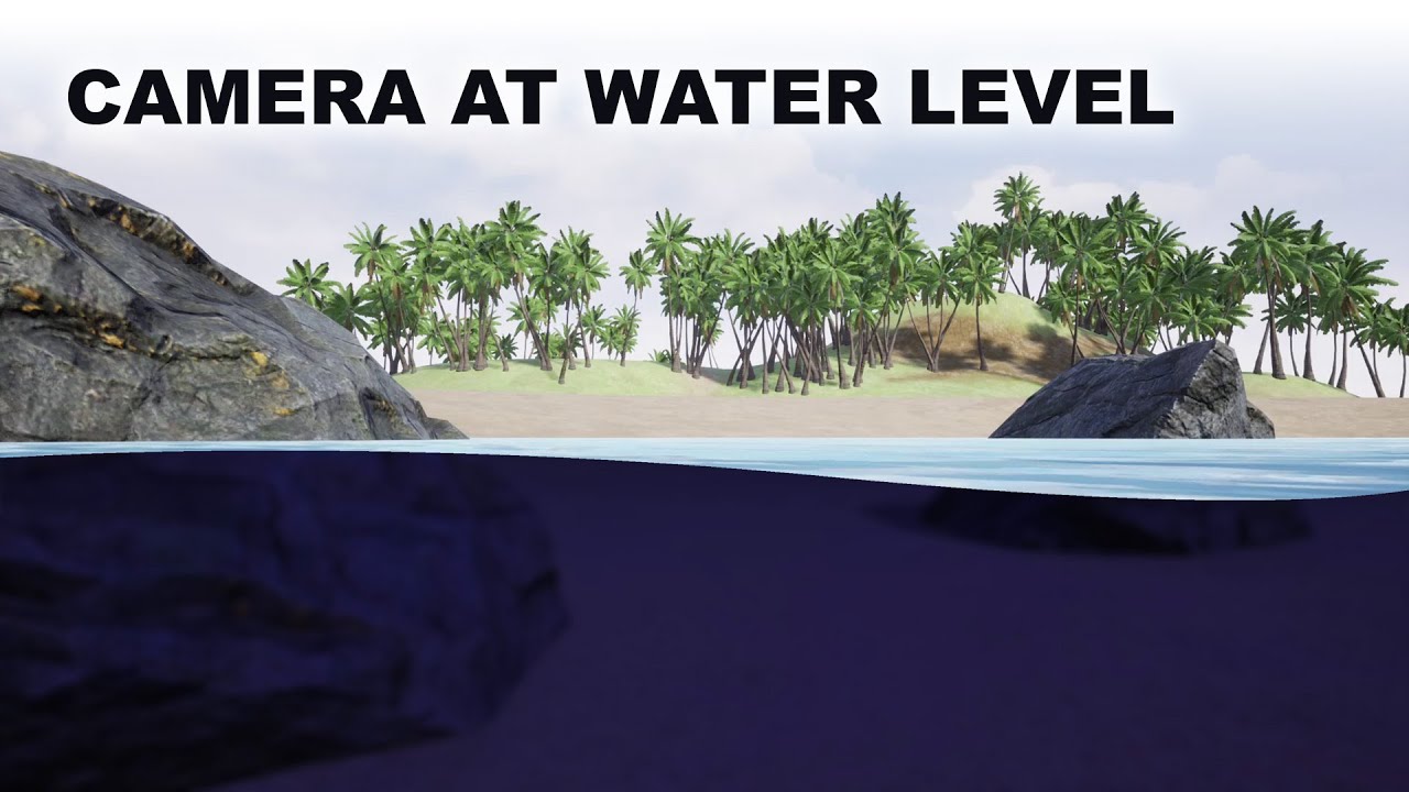
Project files : https://www.patreon.com/posts/41567701
Today I am going to do a little experiment on how to render waterline, a split view of above water and underwater when we place the camera at the water level. Here what I intend to have is above the water line, there should be a normal rendering of the surrounding and under the waterline, th...
Can anyone tell me why i can do something like Cull [_Cull] in my shader to make culling mode a variable, but i cant do same with Lighting parameter?
I remember someone ages ago asking something similar; draw the water effect where a point on the near plane is in the water. So take camera position, add* view direction times near plane distance, now check if that is below water level (based on the height) then go from there.
*Could very well be subtract; not good with signs.
ok thank you!
here
Does Shader graph has concept of executing on vertex shader or fragment like in classic approach? I have function which should execute in vertex shader and then pass data into fragment. Should i pass data through custom interpolator?
In shader graf you do not really pass things over from a vertex to a fragment shader, you have it all in one place anyway
unfortunately it doesnt work
it dose switch between the scene color and the fog color but it doesnt cutoff
is it because im using a blit feature?
Yes.
That's why there are two "stages" to shader graph. The Vertex inputs and the Fragment inputs. At least there are if you're using a fairly recent version.
Custom interpolators are used to pass values from vert to frag in shader graph (SG). SG will create a v2f type of structure internally. So some things like SV_Position and such are "automatic" as it can tell if it needs them from what you design. But if you need to pass a custom value from a calc in your vert() logic, that's where the custom interpolator comes in.
It's basically creating a member variable in the internal v2f that SG uses between vert and frag. Just make sure that the "connections" you make between nodes for your calc are all going in the vertex side so that "branch" of logic in the logic tree is in the vert() function and sets the value of the custom interpolator that you created in the vertex master stack. Don't try to drag frag() side stuff into the calc for that vertex() side stuff. Pretty sure SG enforces this and won't let you connect frag stuff to vert stuff. Also see limits and warnings here:
https://docs.unity3d.com/Packages/com.unity.shadergraph@13.1/manual/Custom-Interpolators.html
Note that some nodes aren't available on the vert side, but that probably won't be a problem for you as it sounds like you're converting existing working code that is designed for a vert() stage. Things that use ddx/ddy are not available in the vertex stage because rasterization hasn't been done yet. LOD levels and MIP maps come to mind, as well as the ddx/ddy functionality.
ok i think i might need to use unity 2023 to make it work.
I don't think so, you should be able to slightly modify what you already have and get it working
You already have something that cuts the water effect so it's only in the bottom half
So you just need to modify it so the position of the cutoff is slightly different
yeah but it doesnt really change the clipping when i look up or down
Can you post a pic of your current graph
ok hold on
here is the one that doesnt cutoff and just swithes colors

and this is the one that cutsoff but doesnt change when rotating the camera

can you post a bigger image; i can't read the text


thx
so?
i am opening up unity, will try to make something myself and hopefully it will work
ok
im also using the blit feature for urp btw
Haven't used it before, I'm assuming the camera for that would be the same as the world camera so it should work the same
i think
this is the code if you dont have it
this works and tracks where the water is cut off by the near plane; i think (except for swapping negate -> step (In) for step (Edge), which are equivalent if the other argument is 0), it is identical to before

the clipping should follow the position of the water on the screen; where it gets cut off by the near plane
huh? what you mean?
the water is some plane, where it gets too close to the camera, it stops being rendered (where it intersects with the camera's near plane) and so the shader calculates which parts of the screen are below or above that intersection line
Soo is it possible for this to wrok with waves?
Work*
Also thanks
It works
But all i need now is for the clipping to follow with the waves
So i gotta digure that out
Figure*
If you can calculate where the waves should be, yes. But that unfortunately sounds hard
Its prolly harder for my case since im using gerstner waves in a for loop
But cant i use the depth of my camera?
To like add
To the clipping
?
Or no
Cus like i saw it on the unreal engine tutorial
Maybe, i'll see the tutorial
this is the video i follwed
https://www.youtube.com/watch?v=4eTC-b0Lolk&t=2280s
Project files : https://www.patreon.com/posts/41567701
Today I am going to do a little experiment on how to render waterline, a split view of above water and underwater when we place the camera at the water level. Here what I intend to have is above the water line, there should be a normal rendering of the surrounding and under the waterline, th...
Its around the end
Like 40minsnin the video
It looks like there they're using just a plane for the water, with no waves?
(aside from a normal map)
But it does move
They're scrolling normal maps across rather than doing any sort of vertex manipulation
Its moving up and down tho
You can see the final result in the end
True; they could be using a vertex displacement of sine(time*frequency) and then copying that over to the cutoff part, or they could be moving the mesh with a script and having that script write to a water height property
But it doesn't look like it's position-dependent which is the part that would make it messy
I mean it uses the scene depth for the up and down movement of the ocean
But idont know how well that will translate to shader graph
Im also not on my pc so i cant test it now
Hey, can anyone here give me some pointers on something procedural? Basically just like the procedural rectangle node in shadergraph, but with a linear gradient out to UV edge. Either of the two outputs pictured are acceptable. Grid lines represent the width/height parameters (pictured would be 4,4).
Either shader graph or code examples are very much appreciated!


IQs blog is the first place I go for procedural stuff like this : https://iquilezles.org/articles/distfunctions2d/
The box or rounded box could give you results like this, e.g.

but going so far as copying the whole scene seems quite bad for performance, storage and such things.
Thanks mate. I figured out my exact use case from there 👍
Preload shaders
How do you make your waterline effect?
Im going to assume you mean depth intersection?
I guess yeah
Basic example here
https://gist.github.com/andrewgotow/cebb2e9eb772ca9e79fec1c7699bfe88

Gist
Unity - Depth Intersection Shader. GitHub Gist: instantly share code, notes, and snippets.
LinearEyeDepth from the depth texture for the depth of the previous fragment. screenpos.z for the current drawing one
I mean yes but also no
I dont knwo how to check if the camera is above or underwater in shadergraph
Th waterline in mu case is screen space and idk if that could work and im also using shadergraph
Ah okay, as in a semi submerged camera
I know how to translate shader code to shader graph so it isnt a problem
Yee
Like half of the camera has underwater effect while the top part of the camera is nirmal
Normal*

Not perfect, but wanted to have a go at a waterline effect to add to my latest stylised ocean shader~🌊
#TechnicallyAChallenge - Underwater
#unity3D #madewithunity #shaders
Likes
1163
Retweets
121
Yeah! Do you know how?
inigo quilez is an absolute god
Ive never done it myself, but I would imagine you calculate the water in clip space in a post process
I meannnnnnnn maybe?
Ill let Cyan respond, Im just guessing and only responding because I misunderstood the question 🙂
I used a similar technique to the one described in this twitter thread, https://twitter.com/_staggart_/status/1411339746828226561
In short, using a C# script to generate a subdivided plane at camera near(ish) plane, using shader that roughly matching the water displacement.
They render this to a separate small res buffer and use it for post-process, but I just render that mesh itself, with a shader that reconstructs world pos from depth buffer to add fog/caustics/etc.
Some background on how I'm rendering the water line, because it's almost arcane 🪄 #unity3d
The key goal is figuring out if a certain pixel on the screen is above, or below water. This in turn can be used to apply effects to a specific part of the screen.
Likes
832
Retweets
147
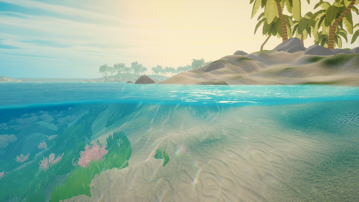
I'm studying shaders more in depth.
- Are projects mostly made with SRP nowadays or still built-in rendering pipeline?
- If in SRP, do most people use the visual node graph tool or mainly just stick to the shader source files
yes
that's pretty cool
- SRP - built-in is the oldest pipeline and AFAIK not receiving any more support
- Whichever you prefer. Lots of people have success with ShaderGraph, others say its not worth learning
I've tried using Graphics.Blit(source, destination, _customMat) but it just results in a solid colour being output?

public class CameraVHSToggle : MonoBehaviour
{
    public RenderTexture _VHSRT;
    private Camera cam;
    [SerializeField] private Material _VHSMat;

    private void Start()
    {
        OnEnable();
    }

    private void OnEnable()
    {
        if (cam == null)
            cam = GetComponent<Camera>();
    }

    private void OnPreRender()
    {
        cam.targetTexture = _VHSRT;
    }

    private void OnRenderImage(RenderTexture source, RenderTexture destination)
    {
        Graphics.Blit(source, destination, _VHSMat);
    }

    private void OnPostRender()
    {
        cam.targetTexture = null;
    }
}
_VHSMat uses a shadergraph shader
You'll likely want to specify the pass index, as shadergraph will generate other passes than the main forward one. Try Graphics.Blit(source, destination, _VHSMat, 0);
I also assume this is Built-in RP as you're using OnRenderImage
Thank you, I've given it a go but it looks like there are other issues, I'm going to rewrite my VHS effect shader as a "real" shader as well
Hey, does anybody know how to make a shader with a 2d texture as input, that simply project that texture on the material but is based on the camera direction, position, etc. (Like in Valorant)? (And if possible for URP?)
(So that no matter where the camera is or how it's rotated, the texture looks the same and like 3 dimensional)
Bit of a random one, but is/has anyone had any trouble with the URP Lit shader recently?
All of a sudden when making a build it's started to crap out on me (this is the default URP lit shader, no changes etc.)
And afterwards the shader disappears from the list, restart Unity and URP is completely broken (Package cannot be found).

I literally just opened this why is i already pink dude how do i fix this

What sort of shader would I need to use to achieve the flat look that these environments have?


If it’s something other than shaders used to create this look, I’d love to know what
At what point do you need to start being concerned about shader performance? In an otherwise pretty non-demanding game in which there could potentially be ~20 max instances of the shader running.
Asking because I'm doing the outline shader hack where you sample four copies of an animated sprite and translate them in all four directions to make an outline
Hm well if I'm reading the profiler correctly, I guess shaders have very little impact on performance
It seems to me this shader is just using diffuse shading without normal maps, plus they probably used lightmaps. The easiest way to achieve that in Unity is to use builtin PBR shader and set all material roughness to 1. In URP, you can manually turn off specular hightlights, which would save you a few more instruction.
Samping typically impacts mobile gpus and integrated gpus
Samping?
yes Sampling
It's probably not a big deal, just test your game on real device and see where it goes
hi, did anyone know how to fix this (texture not seamless in cylinder and sphere)

nvm, i fix it (instead 2d text, i use triplanar instead)
There must be some irony in that compiling shaders for a build is run entirely on the CPU and its really slow
hey why is my thing purple whenever i make it fresh its purple but all the tutorials im following dont have this issure help?

Are you using URP?
if you are using HRDP or SRP the URP Shader graph will show pink instead of the correct oclor
This is just a blank 'lit' shader that I just created, why is Unity messing with the geometry and the position?

yeah im using urp. is there any way to fix it or is it intended?
do any of your other non SG shaders have issues?
no
does the object have a weird scale or in a parent with a werid scale?
not sure then.
You clicked run and it shows pink? and this is a new project setup with URP?
Nope. Scale is 1 on every axis.
moving it around doesn't move the giant version either
it seems independent
is it a sprite?
I've tried across several unity versions, reinstalled the shader graph several times, etc
no
so it is a mesh.
if you change meshes does this happen?
similar/same issue no matter which mesh it's applied to
it's a shader thing
and any shader I make with the shader editor, even if it's just the default and I change nothing, throws a bunch of errors.

does the scaling issue also happen with default shaders?
it looks like there is some invalid transformation of the object's Matrix. Does it always stay at the origin point?
nope
just shadergraph ones
yep.
Never really worked with shaders before so I'm a bit lost here. Shadergraph hasn't had these issues before either.
is your Shadergraph shader touching the Vertex properties?
messing with those can cause matrix issues.
nope
It's just the default Lit shadergraph with a texture in the base color slot

considering switching to Amplify
I've heard good things
Using SG in BiRP is kind of a "new" thing.
The errors/warnings you showed were related to instancing.
Try turning off GPU Instancing on the material, just a wild shot in the dark.
Also check the material in the inspector for other issues. Otherwise might be a bug in SG version.
If you switch the material to use the standard shader, does it fix the problem?
I could use the standard material, but I want to add things like vertex displacement and subsurface scattering
so I needed something with a bit more customization
Amplify worked fine
I get that, it was just a debug action to test.

Cool
I'll switch it back
You've got alpha clipping now too. 🙂
Indeed, I didn't get that far with the shader graph
just created a default shader and it started freaking out so I had to pause for a bit
lol
I don't see an option for GPU instancing in the shader graph, where is that?
usually it's just on the material for the built-in unity ones
It's on the material, set in the inspector.

huh, OK. My bad I guess.
The shader has to support instancing for it to show up, so maybe BiRP generated with SG don't? IDK
Maybe that's why there's warnings.
Are you on the latest version of SG?
I use surface shaders in BiRP, not SG.
yes
And I tried SRP and URP, both had the same issue
Wow. That shouldn't be. I'm at a loss.
PS URP is an SRP.
SRP isn't a thing in itself. It's a category.
Perhaps you mean HDRP?
I'm at a loss, I'd put that SG shader on a basic quad and see what it does.
Hi, does anyone know how you'd use stencil buffers to hide everything above an intersection point? https://i.imgur.com/KwYAOig.gif Right now I have 2 planes intersecting, and I want the vertical plane to only render below the 'waves' of the horizontal plane.
or an alternative way to achieve the effect of creating color beneath a plane with moving waves? I've tried a few things but keep getting stuck.
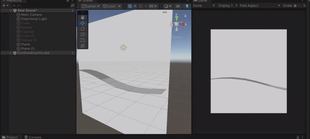
There was a discussion about a similar thing yesterday in case you missed it
<#archived-shaders message>
do you know how i could add a sin wave to the fog split thing you made for me yesterday?
the height (or minus the height) goes into the other input in the Step node
subtract the negate by a sine wave?
in the step node, in the other input, put in e.g. (amplitude*sine(time*frequency))
ohh ok
ok nvm its just giving me epilepsy
Hello everyone! Can someone guide me/refer links on some good reads about lighting in games? Something that describes if a lighting buffer is used and other computations?
oh carp nvm i got it to work i just forgot to put the x value of screen position
will you EVER.. make a break down for this?
if not its fine i just wanna ask
can you help me please? whats going onnn! https://streamable.com/gd4di9
here is a better angle. https://streamable.com/8cmkh0

need to add/remove a negate somewhere, looks like
its still the same because thats what i did at first but somewhere else

try swapping the inputs for the step
?
?

try putting the property into the top slot and the thing from the add into the bottom slot; at 0:46 it looks almost there and you just need to flip which side the water is on i think
.-.
property as in the waves?
orrrr
the edge?
nvm
Which part says how high the waves go?
idk what you mean

here your shader knows what height to go to
the split node?
however it calculates the height at some position
so in the shader when it was flat, it was just 0 in the other side of the step, now put your height [or perhaps minus the height] into that slot instead
of the step node?
here is the code for the gerstner waves if its even relivant to the problem

@karmic hatch
yes
in the version where it was flat, the Add node just before the Step has the position of the points on the near plane; calculate the height of the waves from that, and then plug that into the other side of the step


this adds the waves but it still moves:(


the heck is that?
and how
green is the wave height (plug in whatever wave height you want), blue is the color i've set it to; the output of the step is just 0 on one side and 1 on the other

the quad has the shader applied, then i put two planes with a wave in their vertex shader. Where they're cut off is the near plane of the camera.
soo basically i can use the quad instead of the blit feature?
i'm sure the blit feature makes it more convenient to follow the camera and stuff; I'm just using a quad because it's a mockup for test purposes and i didn't want to set up anything complicated
ok ok
it works on the blit feature
but
the waves change depending on the camera rotation
depending on camera rotation the near plane could intersect with different parts of the waves
two images with the same camera position, just different angles


yea thats my problem
Ill still use the quad method instead for better accuracy for the waves
Hey cyan! How do you get the cutoff to work with the waves? So it wont ahow the waves when your above the water.
Oh wait what do you mean by render this to a separate small res buffer. Whats a small res buffer?
if you ever figure this (seamless wavy waterline rendering) out can you do a tutorial lol. wondering the same, it's very difficult.